Embed Size (px)
Citation preview
2008 APRIL
In this issue ...
www.microwavers.org
• Tributes to Dave Cox, GØRRJ
• The Driscoll VHF Overtone Crys-tal Oscillator .. by GW4DGU
• Using DDS Aliasing to Extend its Frequency Range … by F9HX
• GB3TC Voice repeater
• Activity News .. edited by G8APZ
• GB3CAM coming along nicely
• Microwaves from the Emerald Isle
• Sheffield Round Table - urgent!
Latest News …
• GØRRJ now Silent Key • GB3TC 10GHz Voice Repeater now on air • EI stations buy microwave kits… look out for EIs on 10GHz!
MANY THANKS TO ALL OUR CONTRIBUTORS TO THIS APRIL EDITION.
WITHOUT YOU THERE WOULD BE NO SCATTERPOINT!
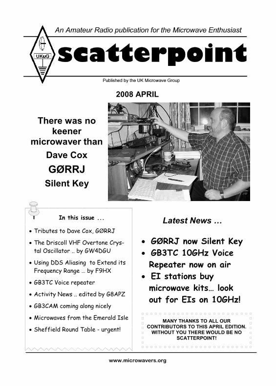
There was no
keener microwaver than
Dave Cox
GØRRJ
Silent Key
G3PHO: [email protected]
Page 2
G3PHO: Peter Day ++44 (0)114 2816701
G3PHO, Peter Day, 146 Springvale Road, Sheffield, S6 3NU, UK
SUBSCRIPTION ENQUIRIES SHOULD BE SENT TO THE UKuG GROUP SECRETARY AT THE ADDRESS SHOWN AT THE TOP OF THIS PAGE
News, views and articles for this newsletter are always welcome. Please send them to G3PHO (preferably by email) to the address shown lower left. The closing date is the Friday following the first Monday of the month if you want your material to be published in the next issue.
UK Microwave Group Contact Information
This edition is being put together earlier than usual as I will be away on a month’s holiday in NZ and Australia by the time you receive it. I will not be back home in the UK until May 20th so please do not send me emails until that date as I don't want to find 5000 mails cogging the mailbox on my return! However, please continue to send G8APZ your Activity News and any adverts via: [email protected] I have already prepared most of the May edition as well, leaving just the Activity news for Robin, G8APZ, to insert. The May edition will not go to the printers until my return so be prepared to receive it a little later than usual … possibly right at the end of the month. While I am in VK, I will be visiting Ian, VK3MO. He‘s not a microwaver but has a fantastic 14MHz antenna system.. four stacked 5 ele monobanders on a >200foot tower. I hope to climb it while I’m there! I will also be seeing my old friend Lyle Patison, VK6ALU (ex VK2ALU) who made the first 10GHz EME VK to G contact back in the mid 90s, G3WDG being at the other end of the path. He is a member of UKuG. Meanwhile, have a very good month of microwave operating..
73 from Peter, G3PHO — Editor
GREMLINS STRIKE AGAIN!
Last month’s Scatterpoint had evidence of a few “ESMs” (also known as Editor’s Senior Moments) ... Page 14 and front page Contents list: The title should read Polish antennas for 5.7GHz (not 24GHz as stated) The diagrams on Page 13 should be enti-tled: "When looking from the back of the horn"
HAVE YOU RENEWED YOUR UKuG SUBSCRIP-TION YET? YOU CAN CHECK THE RENEWAL DATE ON YOUR ENVELOPE ADDRESS LABEL IF YOU RECEIVE A PRINTED SCATTERPOINT. THE DATE IS ON YOUR ADDRESS LABEL. IF YOU STILL DON’T KNOW YOUR RENEWAL DATE PLEASE EMAIL THE SECRETARY, G8KQW, AS SOON AS POSSIBLE!
From the Editor’s Desk
Chairman: G4NNS Brian Coleman
Email: [email protected]
Located: NearAndover(IO91FF) Address: Woodlands, Redenham, Andover, Hants., SP11 9AN Home Tel: -
Secretary: G8KQW Ian Lamb
Email: [email protected]
Located: Hindhead, Surrey Address: Little Court, Churt Road, Hind-head, Surrey GU26 6PD, United Kingdom Home Tel: ++ 44 (0)1428 608844
Treasurer:G4FSG Graham Murchie
Email: [email protected]
Located: Woodbridge(JO02) Address: 42 Catherine Road, Woodbridge, Suffolk, IP12 4JP Home Tel: +44 (0)7860 356775
Scatterpoint Editor: G3PHO, Peter Day
Email: [email protected]
Located: Sheffield (IO93GJ) Address: 146 Springvale Road, Sheffield, S6 3NU, United Kingdom Home Tel: ++44 (0)114 2816701 (after 6pm)
Scatterpoint 2008 APRIL
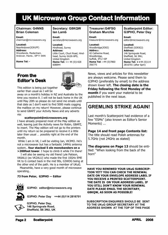
It came as a great shock to almost all who knew him that Dave Cox, at the young age of only 49 years, had passed away on the morning of Mon-day 17th March this year. His funeral took place at Basingstoke Cremato-rium and was attended by so many people that there was not enough room in the chapel for everyone. UK amateur microwaves was well represented. UKuG Chair-man Brian Coleman, G4NNS (a close friend of Dave) was honoured to be asked to speak at the service. In addition to amateur radio, there were dozens of others who represented other
facets of Dave’s very full life ... schoolboy soc-cer and his workplace being just two. Dave had been very seriously ill with cancer for some time but had tried to not let it show. Outside his family, only a handful of close
friends were aware of the situation. In typical cheerful style, he was active on the air and building equipment up to the last fortnight of his life. Anyone who had ever spoken to Dave (seen here in the middle of the photo left) over the air or who had met him personally must have been greatly impressed by him as a person of great integrity and enthusiasm, not just in the field of amateur microwaves but as a devoted family man and work colleague. He had a very close bond with his family and spent many hours a week working with junior soccer leagues in his area. His work colleagues had immense respect for him and were very supportive during the trying months before his death. Many of you will have made microwave QSOs with GØRRJ for he was a very active operator. Indeed, if his callsign was not on the KST chat room list by 0600 each morning you would wonder where he had got to! He was a profilic constructor, working with simple test gear and admitting to learning something new all the time. His website, full of his construction pro-jects, was an inspiration to beginners. The obvi-ous enthusiasm he had for microwaves shone through. Up to very recently, he was putting gear together and had recently become active from home on the challenging 24GHz band. From a personal aspect, I will never forget Dave’s tenacity to make a valid contact. If he couldn't get the full exchange and final RRRs over the microwave band then he wouldn’t claim it as a contact. One of our 10GHz CW QSOs took over an hour to complete!
Rest in Peace Dave ... from Peter G3PHO
Email tributes to Dave are on the next page ….
Page 3 Scatterpoint 2008 APRIL
GØRRJ
Silent Key
From around the UK and Western Europe, tributes to Dave have poured in. Here’s a selection from the many ...
What sad news. I didn't know about his illness, so it was quite a shock. I knew Dave from many QSOs on the microwave bands and was always impressed by his enthusiasm - and his perseverance when conditions were difficult. He made a signifi-cant contribution to microwave activity in the UK. I only met Dave once, at Martlesham in 2006, and was fortunate to sit next to him at the dinner. It soon became apparent that he was an extremely nice guy as well as an enthusiast and I thoroughly enjoyed the evening. I will miss his presence on the bands (and KST) as I'm sure the rest of the UK microwavers will. I know from my own experience how difficult things are for the family left behind and I hope they get the support and friendship they will need to help them through this time. 73 and RIP Dave … Neil, G4BRK
Very sorry to hear this. I've been in contact with Dave from when he decided to use a modified Alcatel system. Another microwaver who will be missed by us all... Dom, F6DRO
We are the poorer for his loss. I have worked Dave many, many times over the years on all bands from 144MHz upwards. His obvious enthusiasm for microwave activity was reflected by the number of contests he was involved with. My last log entry with Dave was a rain scatter contact on 5.7GHz only a week ago . I was unaware of his health problems to the end - he was fully enthusiastic, as usual. On behalf of your many friends at FRARS and SCRBG, 73 and RIP OM. John, G0API
I was very shocked to hear this news today. I worked Dave many times over nearly 30 years on all bands from 144MHz to 10GHz, and particularly enjoyed meeting him at round tables over the past few years. He was a true enthusiast who put in a lot of work to build an effective station, from 432MHz EME back in the G8OPR days to 24GHz most recently. He will be sadly missed on the bands. My sincere condolences go to his family at this terrible time. John, G3XDY
I heard about Dave's condition on Friday and that he was not expected have much longer with us. I was extremely upset to hear that news. I had met Dave on a number of occasions and found him to be a most amiable person and one who was easy to get on with. I had hoped to work Dave on 24GHz, and we came close about a month ago, when conditions were favourable. How-ever, it was not to be. His callsign will be a sad omission from KST. He always seemed to be there, like a beacon and always ready to try for a contact. I'm sure that enthusiasm will carry with him, for ever. Farewell Dave. Sam, G4DDK
So sad to hear that Dave has been released from his fight and suffering. Having been through similar period with a family member, I can understand what Dave's loved ones are going through - and of course it's always sad to loose another keen and active microwaver. Although I haven't been so active of late, I made many QSOs with Dave on the lower bands. My condolences to his family Be at peace, Dave… from Dave, G4HUP
I had the good fortune to meet Dave about three years ago at the RAL round table and enjoyed visiting with him again each of the last two years at the same event. I had the pleasure of being seated next to him at last year's Saturday dinner. He was, as I discovered and as almost everyone else already knew, first and foremost a father and family man and an avid microwaver second. We had discussed the possibility of him
visiting us in the States soon but it was not meant to be. Our condolences go to his lovely wife and sons. Dave has now reached the ultimate DX QTH and in some small way will continue to be a part of the QSOs of all who had the pleasure to know him. Rest in peace, 'RRJ! From Steve Krull, WBØDBS
Although I'm not that active nowadays, Dave was a great help to me when I was on 3cm. He showed great enthusiasm and a love of the hobby. He will sadly be missed by many. All the best to his family in these sad times. John, G7JTT
David, or Coxy as I knew him, lived in Andover when my family and I first lived in Hampshire. We both worked for the same young company Link Electronics, building a share in the Televi-sion Broadcasting world. The company had a number of li-censed amateurs, with a strong interest in microwave and construction within the group. Coxy caught the bug and with characteristic energy decided he would get a license. G8OPR followed in short order, as did all-manner of constructed equip-ment. The first you would know of his latest idea, would be a quietly raised question in the morning or lunch time break, with an enquiry about a particular technical topic. Invariably, only days later, something new would appear on air. I will miss his great energy. Later when I moved to the north of England, it was always a pleasure to find Coxy at one of the many UK television events, with the monster of a wide screen projector “the Edifor” which he looked after. I marveled at the number of miles he traveled. Our thoughts go out to his wife and their young family. No longer will we see his “ever optimist message on KST seeking a contact,” which on many occasions he completed. Peter Blakeborough, G3PYB
Its a very sad loss. I have known Dave since I first got my call. It brings it home that I am the same age as he is. My Deepest sympathy and prayers to his family. Reg, G8VHI It was with great sorrow that I heard the news, first thing this morning, that Dave G0RRJ, had passed away. The Microwave World has lost a fine man today. Dave had been fighting cancer for a long time and he did it with great courage and fortitude. I met him first on Kithill when out on a portable contest and he was on holiday down here. We struck up a good friendship which has been solid over the past six years or so. He then had just recovered from his first bout of this disease, he became a serious microwaver both in building and operating and was well known by many, both here and on the continent. After the 2007 Martlesham round table, which he was not really well enough to attend, he took me to Lane End to test his latest 24GHz system, which worked extremely well. In fact when I went up to see him a few weeks ago he was still furi-ously building for 24GHz. Bring round circuits and transitions to be tested at Brian G4NNS’s QTH. He was a quiet man, very much a family man, who spent a lot of time with his family. He worked hard and was highly respected in his work place but he also played hard. I am going to miss him greatly, as we were always either in QSO or on the phone together. Dave conducted himself with great dignity throught, consid-ering he was only about 49 which makes this even more a tragedy. Rest in peace Dave. Ralph G4ALY
We also acknowledge tributes from G0EWN, G4BAO, G4EAT, G4PBP, GM4CXM, F6DKW and F9OE
Scatterpoint Page 4 2008 APRIL
Page 5 Scatterpoint 2008 APRIL
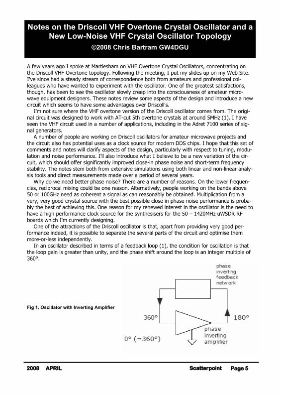
A few years ago I spoke at Martlesham on VHF Overtone Crystal Oscillators, concentrating on the Driscoll VHF Overtone topology. Following the meeting, I put my slides up on my Web Site. I've since had a steady stream of correspondence both from amateurs and professional col-leagues who have wanted to experiment with the oscillator. One of the greatest satisfactions, though, has been to see the oscillator slowly creep into the consciousness of amateur micro-wave equipment designers. These notes review some aspects of the design and introduce a new circuit which seems to have some advantages over Driscoll's. I'm not sure where the VHF overtone version of the Driscoll oscillator comes from. The origi-nal circuit was designed to work with AT-cut 5th overtone crystals at around 5MHz (1). I have seen the VHF circuit used in a number of applications, including in the Adret 7100 series of sig-nal generators. A number of people are working on Driscoll oscillators for amateur microwave projects and the circuit also has potential uses as a clock source for modern DDS chips. I hope that this set of comments and notes will clarify aspects of the design, particularly with respect to tuning, modu-lation and noise performance. I'll also introduce what I believe to be a new variation of the cir-cuit, which should offer significantly improved close-in phase noise and short-term frequency stability. The notes stem both from extensive simulations using both linear and non-linear analy-sis tools and direct measurements made over a period of several years. Why do we need better phase noise? There are a number of reasons. On the lower frequen-cies, reciprocal mixing could be one reason. Alternatively, people working on the bands above 50 or 100GHz need as coherent a signal as can reasonably be obtained. Multiplication from a very, very good crystal source with the best possible close in phase noise performance is proba-bly the best of achieving this. One reason for my renewed interest in the oscillator is the need to have a high performance clock source for the synthesisers for the 50 – 1420MHz uWSDR RF boards which I'm currently designing. One of the attractions of the Driscoll oscillator is that, apart from providing very good per-formance indeed, it is possible to separate the several parts of the circuit and optimise them more-or-less independently. In an oscillator described in terms of a feedback loop (1), the condition for oscillation is that the loop gain is greater than unity, and the phase shift around the loop is an integer multiple of 360°. Fig 1. Oscillator with Inverting Amplifier
Notes on the Driscoll VHF Overtone Crystal Oscillator and a New Low-Noise VHF Crystal Oscillator Topology
©2008 Chris Bartram GW4DGU
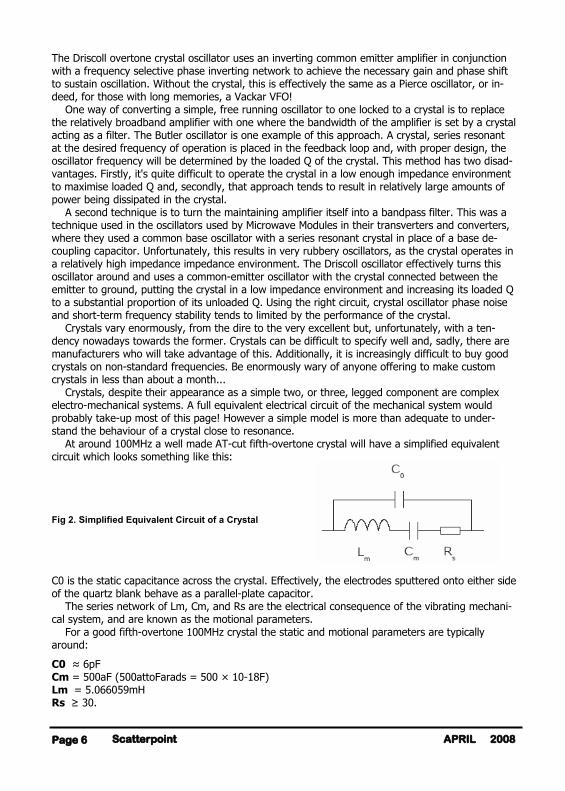
The Driscoll overtone crystal oscillator uses an inverting common emitter amplifier in conjunction with a frequency selective phase inverting network to achieve the necessary gain and phase shift to sustain oscillation. Without the crystal, this is effectively the same as a Pierce oscillator, or in-deed, for those with long memories, a Vackar VFO! One way of converting a simple, free running oscillator to one locked to a crystal is to replace the relatively broadband amplifier with one where the bandwidth of the amplifier is set by a crystal acting as a filter. The Butler oscillator is one example of this approach. A crystal, series resonant at the desired frequency of operation is placed in the feedback loop and, with proper design, the oscillator frequency will be determined by the loaded Q of the crystal. This method has two disad-vantages. Firstly, it's quite difficult to operate the crystal in a low enough impedance environment to maximise loaded Q and, secondly, that approach tends to result in relatively large amounts of power being dissipated in the crystal. A second technique is to turn the maintaining amplifier itself into a bandpass filter. This was a technique used in the oscillators used by Microwave Modules in their transverters and converters, where they used a common base oscillator with a series resonant crystal in place of a base de-coupling capacitor. Unfortunately, this results in very rubbery oscillators, as the crystal operates in a relatively high impedance impedance environment. The Driscoll oscillator effectively turns this oscillator around and uses a common-emitter oscillator with the crystal connected between the emitter to ground, putting the crystal in a low impedance environment and increasing its loaded Q to a substantial proportion of its unloaded Q. Using the right circuit, crystal oscillator phase noise and short-term frequency stability tends to limited by the performance of the crystal. Crystals vary enormously, from the dire to the very excellent but, unfortunately, with a ten-dency nowadays towards the former. Crystals can be difficult to specify well and, sadly, there are manufacturers who will take advantage of this. Additionally, it is increasingly difficult to buy good crystals on non-standard frequencies. Be enormously wary of anyone offering to make custom crystals in less than about a month... Crystals, despite their appearance as a simple two, or three, legged component are complex electro-mechanical systems. A full equivalent electrical circuit of the mechanical system would probably take-up most of this page! However a simple model is more than adequate to under-stand the behaviour of a crystal close to resonance. At around 100MHz a well made AT-cut fifth-overtone crystal will have a simplified equivalent circuit which looks something like this: Fig 2. Simplified Equivalent Circuit of a Crystal C0 is the static capacitance across the crystal. Effectively, the electrodes sputtered onto either side of the quartz blank behave as a parallel-plate capacitor. The series network of Lm, Cm, and Rs are the electrical consequence of the vibrating mechani-cal system, and are known as the motional parameters. For a good fifth-overtone 100MHz crystal the static and motional parameters are typically around:
C0 ≈ 6pF Cm = 500aF (500attoFarads = 500 × 10-18F) Lm = 5.066059mH Rs ≥ 30.
Scatterpoint Page 6 2008 APRIL

The unloaded Q of the crystal is therefore in the region of 100000! However, be warned … I have measured crystals, using a network analyser, with Qs much less than this. Less than 10000 has become depressingly common! To keep the loaded Q as high as possible, a series network needs to have as small source and load resistances as possible. Professionally, series-mode crystals below 125MHz are now measured between 12.5. resistive source and load impedances and series resonance is defined as the fre-quency at which the phase shift across the crystal is zero degrees and at which there is maximum power transfer. This is defined by IEC Standard 60444. Incidentally, parallel mode crystals are measured in a similar way, except that the source and load impedances will each be shunted by twice the desired crystal load capacitance and that the conditions for parallel resonance are zero phase shift at the frequency where there is a transmission zero. Many years ago, Dave Leeson, W6NL, ex-W6QHS, published a paper in an IEEE journal (3) analysing the noise performance of a generalised oscillator. He suggested that oscillator noise can be modelled by three main parameters:
• the loaded Q of the resonator
• the available power at the input of the sustaining amplifier
• the noise power at the same point In fact, it can get quite a lot more complex than that and there have been subsequent papers which have introduced more complex models in order to describe oscillators more accurately but, as a simple set of parameters for understanding and optimising a low noise oscillator, Leeson's original paper is still very useful. The loaded Q of the resonator is the probably the most difficult of the parameters to achieve. As I hinted above, the Driscoll oscillator does this in a particularly neat way: it connects the crystal between the emitter of the oscillator transistor and ground. That's effectively across an impedance of maybe 30ohms, resulting in a loaded Q of around 50000 with the crystal parameters noted above. Reducing the emitter impedance by increasing the bias current in the transistor is clearly a good idea, providing steps are taken to avoid over-dissipating the crystal. More of that later! The resonator loaded Q has little to do with the loaded Q of the feedback network. Certainly, changes in the phase response of the feedback loop will cause small variations in frequency but, providing the loaded Q of the feedback network is kept low, the crystal will be firmly in charge! The best way to adjust the phase of the feedback network and to trim the frequency of the oscil-lator, is to vary either the inductor or capacitor in the series arm of the feedback network. Chang-
ing the shunt capacitors will have a significant effect on the impedance matching, which is probably not desirable... Incidentally, one useful indication that a crystal oscillator is properly designed is that the oscilla-tor will operate on a frequency close to the zero-phase frequency of the crystal. Another is that it shouldn't be possible to pull the frequency of the oscillator very far. The pulling range of a good crystal in a well designed oscillator at around 100MHz should be around ±300Hz.
Page 7 Scatterpoint 2008 APRIL
Fig 3. Outline Schematic of Driscoll VHF Overtone Crystal Oscillator.
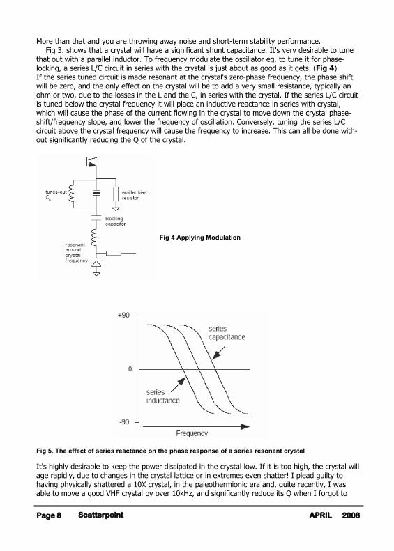
More than that and you are throwing away noise and short-term stability performance. Fig 3. shows that a crystal will have a significant shunt capacitance. It's very desirable to tune that out with a parallel inductor. To frequency modulate the oscillator eg. to tune it for phase-locking, a series L/C circuit in series with the crystal is just about as good as it gets. (Fig 4) If the series tuned circuit is made resonant at the crystal's zero-phase frequency, the phase shift will be zero, and the only effect on the crystal will be to add a very small resistance, typically an ohm or two, due to the losses in the L and the C, in series with the crystal. If the series L/C circuit is tuned below the crystal frequency it will place an inductive reactance in series with crystal, which will cause the phase of the current flowing in the crystal to move down the crystal phase-shift/frequency slope, and lower the frequency of oscillation. Conversely, tuning the series L/C circuit above the crystal frequency will cause the frequency to increase. This can all be done with-out significantly reducing the Q of the crystal.
Fig 4 Applying Modulation
Fig 5. The effect of series reactance on the phase response of a series resonant crystal It's highly desirable to keep the power dissipated in the crystal low. If it is too high, the crystal will age rapidly, due to changes in the crystal lattice or in extremes even shatter! I plead guilty to having physically shattered a 10X crystal, in the paleothermionic era and, quite recently, I was able to move a good VHF crystal by over 10kHz, and significantly reduce its Q when I forgot to
Scatterpoint Page 8 2008 APRIL
include the limiter in a prototype oscillator... Another very good reason for including limiting in a crystal oscillator, is that crystals exhibit a marked tendency to 'drive level dependence' of a number of parameters. Usually, DLD is only considered with respect to Rs but it is also present in the frequency stability of the crystal. I've seen a figure of 1 part in 109 quoted for a 1% change in drive level. In a high performance oscil-lator, that starts to become significant. Typically, the crystal dissipation shouldn't exceed about 250µW. A pair of 'crossed' schottky diodes across the collector circuit will result in an output voltage of ~0.5V peak-to-peak. This will be stepped-down to about 0.3V p-p at the base of the bottom transistor of the maintaining ampli-fier, and if the impedance at the emitter of that transistor is of the order of 30O, about half the voltage will appear across the loss resistance of the crystal, resulting in a crystal dissipation of about 100µW. It is also important to keep the maintaining amplifier operating as a low-noise class-A amplifier. To do this, not only is it important to keep the drive to the amplifier within reasonable limits, so that the noise performance of the amplifier isn't compromised by driving the amplifier into satura-tion, but the amplifier should have a stable instantaneous impedance through each cycle. If the amplifier cuts-off for part of each cycle, the impedance presented by the emitter will rise, and result in a reduction of loaded Q. In any high performance oscillator, it is essential to minimise sources of noise in and around the maintaining amplifier. With very low noise oscillators, this is particularly important. Effectively, low-frequency amplitude domain noise from transistors, resistors and power sources gets turned into phase noise by a modulation process. With suitable transistors and clean power supplies, the most difficult noise source to eliminate is Johnson noise generated by biassing resistors. The classic Driscoll oscillator topology uses series resistors to supply base bias. This is more important in the case of the lower transistor in the cascode amplifier, which usually forms the maintaining amplifier in my designs, than in the upper transistor. A New Oscillator Topology? I've used the Driscoll topology extensively in my work. Unfortunately, that has rather limited my ability to publish other than general information about the oscillator. However, I've recently come-up with an oscillator circuit which, although it derives from Driscoll's work, seems to take another step forward, and that work owes nothing to my clients! Essentially, my new topology replaces the shunt-C, series-L, series-C, shunt-C bandpass phase-inverting feedback network used by Driscoll, with a shunt-L, series-C, series-L, shunt-L, phase-inverting bandpass network. This has the advantage of eliminating series resistor feeds and thus the Johnson noise generated by them. It also provides some circuit simplification. A further ad-vantage is that the source impedance seen by the lower transistor at low frequencies approaches zero, which leads to good LF and 1/f noise performance and therefore good phase-noise and short-term frequency stability performance. Incidentally, the emitter bias resistor is in parallel with the crystal loss resistance and shunted with a low value inductor at DC, so there is not a signifi-cant advantage in replacing it with a low-noise current source, although I once thought that. It is also possible to eliminate the series inductor in the phase inverting bandpass filter. This can result in a 'peaky' highpass filter with the correct phase response. This approach is fine for most 3rd overtone crystals, although the extra selectivity of the bandpass network is likely to reduce the risk of higher order overtone crystals oscillating on unwanted overtones.
Page 9 Scatterpoint 2008 APRIL
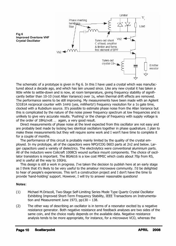
Fig 6 Improved Overtone VHF Crystal Oscillator The schematic of a prototype is given in Fig 6. In this I have used a crystal which was manufac-tured about a decade ago, and which has lain unused since. Like any new crystal it has taken a little while to settle-down and is now, at room temperature, giving frequency stability of signifi-cantly better than 10-10 (root Allan Variance) over 1s, when thermal drift effects are removed. The performance seems to be still improving. My measurements have been made with an Agilent 53181A reciprocal counter with 1mHz (yes, millihertz!) frequency resolution for a 1s gate time, clocked with a Rubidium source. It's possible to estimate phase noise from the Allan Variance but this is complicated by the nature of the noise power frequency spectrum at low frequencies and is unlikely to give very accurate results. 'Pushing' or the change of frequency with supply voltage is of the order of 18Hz/volt … again, a very good result. Direct measurements of phase noise at the level expected from this oscillator are not easy and are probably best made by locking two identical oscillators together in phase quadrature. I plan to make these measurements but they will require some work and I won't have time to complete it for a couple of months. The performance of this circuit is probably mainly limited by the quality of the crystal em-ployed. In my prototype, all of the capacitors were NPO/COG 0603 parts at 2n2 and below. Lar-ger capacitors used a variety of dielectrics. The electrolytics were conventional aluminium parts. All of the inductors were Coilcraft 1008CS wound surface mount components. The choice of oscil-lator transistors is important. The BGA616 is a low cost MMIC which costs about 70p from RS, and is useful all the way to 10GHz. This design is still a work in progress. I've taken the decision to publish here at an early stage as I think that it's likely to be very useful to the amateur microwave community. I'd be delighted to hear of people's experiences. This isn't a construction project and I don't have the time to provide 'hand-holding' support. However, I will try to answer reasonable questions! Notes: (1) Michael M.Driscoll, Two-Stage Self-Limiting Series Mode Type Quartz Crystal Oscillator
Exhibiting Improved Short-Term Frequency Stability, IEEE Transactions on Instrumenta-tion and Measurement June 1973, pp130 – 138.
(2) The other way of describing an oscillator is in terms of a resonator excited by a negative resistance generator. Both negative resistance and feedback analyses are two sides of the same coin, and the choice really depends on the available data. Negative resistance analysis tends to be more appropriate, for instance, for a microwave VCO, whereas the
Scatterpoint Page 10 2008 APRIL
feedback loop model is my choice at VHF and below.
(3) D.B.Leeson, A Simple Model of Feedback Oscillator Noise Spectrum, Proceedings of the IEEE, February 1966, pp.329 -330
(4) Leeson describes the carrier to noise power ratio (in dB) at a given frequency offset from the carrier:
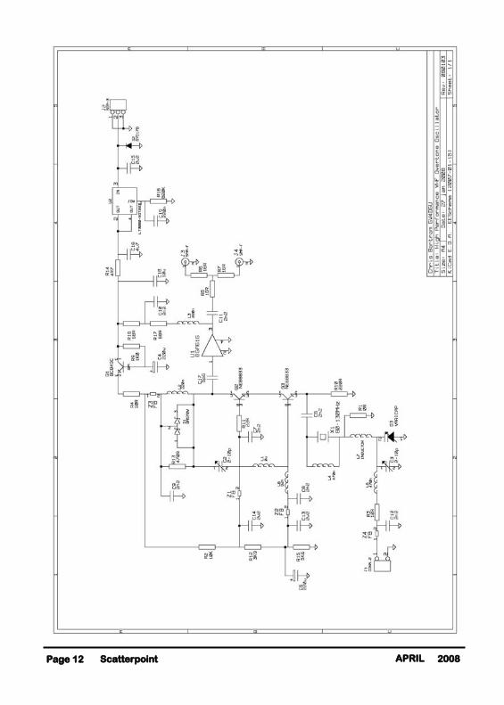
See page 12 for Fig 7: Schematic of Prototype ….
Page 11 Scatterpoint 2008 APRIL
GB3KEU 5.7GHz BEACON ON AIR IN EARLY APRIL
Some of you will be glad to hear that I've finally completed the long awaited GB3KEU beacon and will have installed it at our local Sheffield Amateur Radio club by the time you read this. Presently it's inside my garage run-ning on soak test and appears to be working fine, although the CW note could be a little better (very, very slight random jitter of a few Hz now and then). I suspect the crystal but I only heard it on 5.7GHz the other day after I connected the G8ACE OCXO to the DB6NT beacon module and PA. It's not bad but not quite as good as my own DB6NT transverter (which uses a DB6NT crystal heater only!). All that said, it's staying well within a 25Hz bandwidth on my receiver for hours and hours, the only apparent drift being that of the receiver. It remains exactly on frequency in relation to my Adret marker (locked to an external hi stab source which is running 24/7) so I guess it will more than suffice!
Frequency: 5760.925MHz. FSK keying: Nominally 400Hz shift. Antenna: 10dB slotted waveguide Power: 25W erp. Location: IO93GH. NGR SK350811
This beacon would not have been possible without the very generous donation of a brand new DB6NT beacon driver module and new DB6NT PA by Peter G3LRP. The slotted waveguide antenna was donated by the G3ZME Group (Telford), the keyer by Chris, G8BKE and the OCXO, enclosure and mains PSU by Peter, G3PHO. Thanks also to Peter G3PYB for other assistance. The beacon is located on the roof of the Sheffield A.R.C premises, which itself is rented at the Sheffield Transport Sports Club at Meadowhead, Sheffield. The take off is good to the North, through East and down to SSW. To the west, there are some building obstruc-tions locally and then the Peak District hills.
Reception reports are most welcome! Please email Peter G3PHo at: [email protected]
Scatterpoint Page 12 2008 APRIL
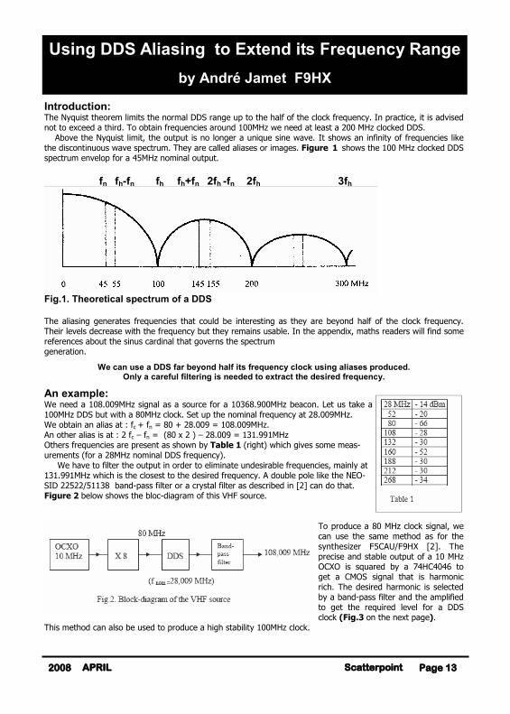
Introduction: The Nyquist theorem limits the normal DDS range up to the half of the clock frequency. In practice, it is advised not to exceed a third. To obtain frequencies around 100MHz we need at least a 200 MHz clocked DDS. Above the Nyquist limit, the output is no longer a unique sine wave. It shows an infinity of frequencies like the discontinuous wave spectrum. They are called aliases or images. Figure 1 shows the 100 MHz clocked DDS spectrum envelop for a 45MHz nominal output. fn fh-fn fh fh+fn 2fh -fn 2fh 3fh
Fig.1. Theoretical spectrum of a DDS The aliasing generates frequencies that could be interesting as they are beyond half of the clock frequency. Their levels decrease with the frequency but they remains usable. In the appendix, maths readers will find some references about the sinus cardinal that governs the spectrum generation.
We can use a DDS far beyond half its frequency clock using aliases produced. Only a careful filtering is needed to extract the desired frequency.
An example: We need a 108.009MHz signal as a source for a 10368.900MHz beacon. Let us take a 100MHz DDS but with a 80MHz clock. Set up the nominal frequency at 28.009MHz. We obtain an alias at : fc + fn = 80 + 28.009 = 108.009MHz. An other alias is at : 2 fc – fn = (80 x 2 ) – 28.009 = 131.991MHz Others frequencies are present as shown by Table 1 (right) which gives some meas-urements (for a 28MHz nominal DDS frequency). We have to filter the output in order to eliminate undesirable frequencies, mainly at 131.991MHz which is the closest to the desired frequency. A double pole like the NEO-SID 22522/51138 band-pass filter or a crystal filter as described in [2] can do that. Figure 2 below shows the bloc-diagram of this VHF source.
To produce a 80 MHz clock signal, we can use the same method as for the synthesizer F5CAU/F9HX [2]. The precise and stable output of a 10 MHz OCXO is squared by a 74HC4046 to get a CMOS signal that is harmonic rich. The desired harmonic is selected by a band-pass filter and the amplified to get the required level for a DDS clock (Fig.3 on the next page).
This method can also be used to produce a high stability 100MHz clock.
Page 13 Scatterpoint 2008 APRIL
Using DDS Aliasing to Extend its Frequency Range
by André Jamet F9HX
Scatterpoint Page 14 2008 APRIL
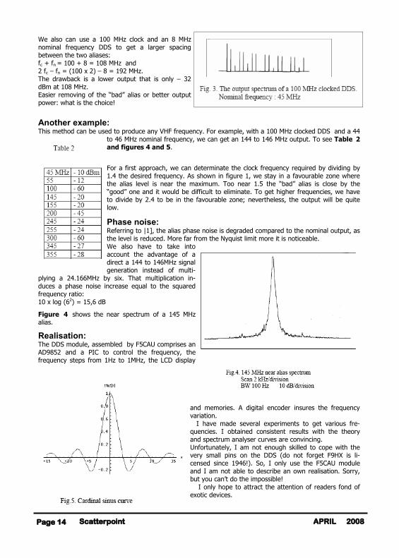
We also can use a 100 MHz clock and an 8 MHz nominal frequency DDS to get a larger spacing between the two aliases: fc + fn = 100 + 8 = 108 MHz and 2 fc – fn = (100 x 2) – 8 = 192 MHz. The drawback is a lower output that is only – 32 dBm at 108 MHz. Easier removing of the “bad” alias or better output power: what is the choice!
Another example: This method can be used to produce any VHF frequency. For example, with a 100 MHz clocked DDS and a 44
to 46 MHz nominal frequency, we can get an 144 to 146 MHz output. To see Table 2 and figures 4 and 5.
For a first approach, we can determinate the clock frequency required by dividing by 1.4 the desired frequency. As shown in figure 1, we stay in a favourable zone where the alias level is near the maximum. Too near 1.5 the “bad” alias is close by the “good” one and it would be difficult to eliminate. To get higher frequencies, we have to divide by 2.4 to be in the favourable zone; nevertheless, the output will be quite low.
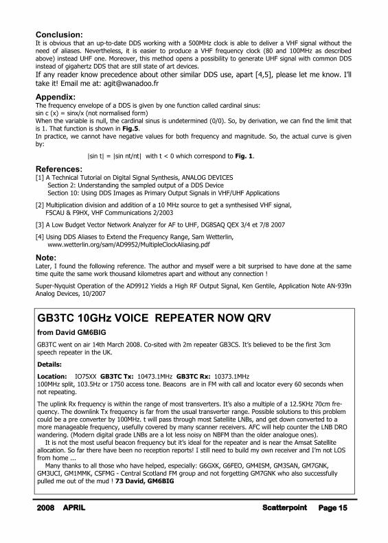
Phase noise: Referring to |1], the alias phase noise is degraded compared to the nominal output, as the level is reduced. More far from the Nyquist limit more it is noticeable. We also have to take into account the advantage of a direct a 144 to 146MHz signal generation instead of multi-
plying a 24.166MHz by six. That multiplication in-duces a phase noise increase equal to the squared frequency ratio: 10 x log (62) = 15,6 dB
Figure 4 shows the near spectrum of a 145 MHz alias.
Realisation: The DDS module, assembled by F5CAU comprises an AD9852 and a PIC to control the frequency, the frequency steps from 1Hz to 1MHz, the LCD display
and memories. A digital encoder insures the frequency variation. I have made several experiments to get various fre-quencies. I obtained consistent results with the theory and spectrum analyser curves are convincing. Unfortunately, I am not enough skilled to cope with the very small pins on the DDS (do not forget F9HX is li-censed since 1946!). So, I only use the F5CAU module and I am not able to describe an own realisation. Sorry, but you can’t do the impossible! I only hope to attract the attention of readers fond of exotic devices.
Page 15 Scatterpoint 2008 APRIL
Conclusion: It is obvious that an up-to-date DDS working with a 500MHz clock is able to deliver a VHF signal without the need of aliases. Nevertheless, it is easier to produce a VHF frequency clock (80 and 100MHz as described above) instead UHF one. Moreover, this method opens a possibility to generate UHF signal with common DDS instead of gigahertz DDS that are still state of art devices. If any reader know precedence about other similar DDS use, apart [4,5], please let me know. I’ll take it! Email me at: [email protected]
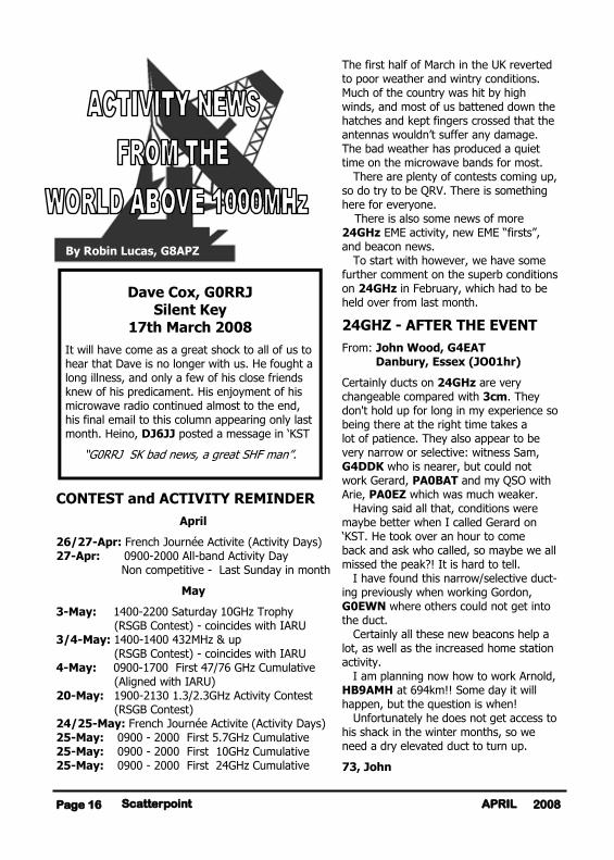
Appendix: The frequency envelope of a DDS is given by one function called cardinal sinus: sin c (x) = sinx/x (not normalised form) When the variable is null, the cardinal sinus is undetermined (0/0). So, by derivation, we can find the limit that is 1. That function is shown in Fig.5. In practice, we cannot have negative values for both frequency and magnitude. So, the actual curve is given by:
|sin t| = |sin πt/πt| with t < 0 which correspond to Fig. 1.
References: [1] A Technical Tutorial on Digital Signal Synthesis, ANALOG DEVICES Section 2: Understanding the sampled output of a DDS Device Section 10: Using DDS Images as Primary Output Signals in VHF/UHF Applications
[2] Multiplication division and addition of a 10 MHz source to get a synthesised VHF signal, F5CAU & F9HX, VHF Communications 2/2003
[3] A Low Budget Vector Network Analyzer for AF to UHF, DG8SAQ QEX 3/4 et 7/8 2007
[4] Using DDS Aliases to Extend the Frequency Range, Sam Wetterlin, www.wetterlin.org/sam/AD9952/MultipleClockAliasing.pdf
Note: Later, I found the following reference. The author and myself were a bit surprised to have done at the same time quite the same work thousand kilometres apart and without any connection !
Super-Nyquist Operation of the AD9912 Yields a High RF Output Signal, Ken Gentile, Application Note AN-939n Analog Devices, 10/2007
GB3TC 10GHz VOICE REPEATER NOW QRV
from David GM6BIG
GB3TC went on air 14th March 2008. Co-sited with 2m repeater GB3CS. It’s believed to be the first 3cm speech repeater in the UK.
Details:
Location: IO75XX GB3TC Tx: 10473.1MHz GB3TC Rx: 10373.1MHz 100MHz split, 103.5Hz or 1750 access tone. Beacons are in FM with call and locator every 60 seconds when not repeating.
The uplink Rx frequency is within the range of most transverters. It’s also a multiple of a 12.5KHz 70cm fre-quency. The downlink Tx frequency is far from the usual transverter range. Possible solutions to this problem could be a pre converter by 100MHz. t will pass through most Satellite LNBs, and get down converted to a more manageable frequency, usefully covered by many scanner receivers. AFC will help counter the LNB DRO wandering. (Modern digital grade LNBs are a lot less noisy on NBFM than the older analogue ones). It is not the most useful beacon frequency but it’s ideal for the repeater and is near the Amsat Satellite allocation. So far there have been no reception reports! I still need to build my own receiver and I’m not LOS from home ... Many thanks to all those who have helped, especially: G6GXK, G6FEO, GM4ISM, GM3SAN, GM7GNK, GM3UCI, GM1MMK, CSFMG - Central Scotland FM group and not forgetting GM7GNK who also successfully pulled me out of the mud ! 73 David, GM6BIG
The first half of March in the UK reverted to poor weather and wintry conditions. Much of the country was hit by high winds, and most of us battened down the hatches and kept fingers crossed that the antennas wouldn’t suffer any damage. The bad weather has produced a quiet time on the microwave bands for most. There are plenty of contests coming up, so do try to be QRV. There is something here for everyone. There is also some news of more 24GHz EME activity, new EME “firsts”, and beacon news. To start with however, we have some further comment on the superb conditions on 24GHz in February, which had to be held over from last month.
24GHZ - AFTER THE EVENT
From: John Wood, G4EAT Danbury, Essex (JO01hr)
Certainly ducts on 24GHz are very changeable compared with 3cm. They don't hold up for long in my experience so being there at the right time takes a lot of patience. They also appear to be very narrow or selective: witness Sam, G4DDK who is nearer, but could not work Gerard, PA0BAT and my QSO with Arie, PA0EZ which was much weaker. Having said all that, conditions were maybe better when I called Gerard on ‘KST. He took over an hour to come back and ask who called, so maybe we all missed the peak?! It is hard to tell. I have found this narrow/selective duct-ing previously when working Gordon, G0EWN where others could not get into the duct. Certainly all these new beacons help a lot, as well as the increased home station activity. I am planning now how to work Arnold, HB9AMH at 694km!! Some day it will happen, but the question is when! Unfortunately he does not get access to his shack in the winter months, so we need a dry elevated duct to turn up.
73, John
CONTEST and ACTIVITY REMINDER
April
26/27-Apr: French Journée Activite (Activity Days) 27-Apr: 0900-2000 All-band Activity Day Non competitive - Last Sunday in month
May
3-May: 1400-2200 Saturday 10GHz Trophy (RSGB Contest) - coincides with IARU 3/4-May: 1400-1400 432MHz & up (RSGB Contest) - coincides with IARU 4-May: 0900-1700 First 47/76 GHz Cumulative (Aligned with IARU) 20-May: 1900-2130 1.3/2.3GHz Activity Contest (RSGB Contest) 24/25-May: French Journée Activite (Activity Days) 25-May: 0900 - 2000 First 5.7GHz Cumulative 25-May: 0900 - 2000 First 10GHz Cumulative 25-May: 0900 - 2000 First 24GHz Cumulative
By Robin Lucas, G8APZ
Scatterpoint Page 16 2008 APRIL
Dave Cox, G0RRJ Silent Key
17th March 2008
It will have come as a great shock to all of us to hear that Dave is no longer with us. He fought a long illness, and only a few of his close friends knew of his predicament. His enjoyment of his microwave radio continued almost to the end, his final email to this column appearing only last month. Heino, DJ6JJ posted a message in ‘KST
“G0RRJ SK bad news, a great SHF man”.
From: Gordon Fiander, G0EWN Sheffield (IO93fk)
The good conditions over the weekend of 16th/17th Feb, and on Monday 18th Feb were as a result of the formation of a duct under high pressure conditions. Exceptionally cold air meant that total moisture content was very low in the lower atmosphere, perfect for mm wave contacts. Very sharp boundaries/gradients in temperature and humidity formed, again ideal for mm wave contacts. The 'launch' angle is very critical under these circumstances and with narrow beams. Having elevation control would allow the launch angle to be adjusted for best fit. In total I made 4 QSOs over 240km--Sunday G4DDK, Monday G4EAT, G4DDK and G8APZ. Tests on Sunday with G4EAT in the morning, and G4DDK in the evening on 3cm showed the band behaving as almost LOS with end stopping signals, definitely the right conditions for testing the higher microwave bands. Checking the setting on my dish showed I had a negative elevation of around 1.5 degrees, or in other words I was beaming at the horizon for my location (230m asl.) On both nights I had to wait until around 9.30pm before the bands opened, which is significant as others at lower elevations found the ducting accessible shortly after dark. As a rule of thumb, for troposcatter a slight degree of elevation of half the dish's beamwidth is useful. For LOS both beams should be fully aligned to start with. In all cases fine elevation control is very useful for peaking signals. RS requires full elevation control to get the most out of the mode, though DX contacts are usu-ally at troposcatter type elevation angles. The importance of cold temperatures is evi-dent by a simple scattergraph - almost all DX mm wave contacts are during the winter months, RS being the exception. All my DX on 24GHz has taken place between November and February. Gordon G0EWN
BEACON NEWS
Lorenz, DL6NCI provides some information on the DB0FGB beacon complex in JO50wb at Schneeberg / Fichtelgebirge (1100m asl with the antennas at 60m above ground level).
On 15th March, 2008, Lorenz announced:
“All beacons are QRT for some weeks. We have to reduce the power consumption. We hope to be "on air" again by the end of April 2008. Some beacons will then have GPS controlled oscillators. More info later.” The beacons at DG0FGB are on 2320.833, 3400.833, 5760.833, 10368.833, 24048.833 47088.833 and 76032.833 (all MHz of course).
EME - 24GHz FIRSTS FROM OK
Members of the Radio Club OK1KIR,(JO70eb) are now on 24GHz EME, having completed the rig after 4 years. They made five EME QSOs on Sunday, 9th March (times in UTC):
11:03 24048.100 MHz DF1OI O/O 11:34 24048.100 MHz DK7LJ O/O fb 14:01 24048.200 MHz LX1DB 449/449 16:01 24048.100 MHz W5LUA 549/449 17:06 24048.150 MHz VE4MA O/O
Vladimir, OK1DAK wrote:- “We are really happy with every contact, espe-cially the first OK-LX and OK-VE QSOs. Signals showed frequency spreading from about 100Hz up to 300Hz at maximum on Spectran. There were very clean (narrow) signals during the QSO with DK7LJ and later on quite clean from LX1DB and especially from W5LUA. RX CW bandwidth of about 1kHz was optimum for most signals during the day. Sun noise was 14.8dB during the morning at 09:00 (lightly cloudy) and 14.4 dB during the afternoon at elevation 43deg (more cloudy). The respective Moon noise was approx. 1.95 dB in both cases. The antenna beamwidth is just over 0.2deg (hard to measure on noise sources of 0.5 deg size). We used F1EHN Moon track-ing software with incremental steps of 0.02 degr OK1KIR 24GHz rig: Primary solid dish 4.5m, horn feed - linear polarization with the transverter, TWT and PSU all mounted at the focal point and rotateable over ±90deg. The LNA from DB6NT approx. 1.5dB and RF output power of about 20W with proper sequencing to operate safely with the LNA. We are ready for anybody else interested in tests, just send an e-mail in advance! Vy 73, Vladimir, OK1DAK for OK1KIR <[email protected]>
Page 17 Scatterpoint 2008 APRIL
23cm EME FIRST - OK-3A
On 22nd March, 2008, Zdenek, OK1DFC made a 23cm EME QSO with Bodo, DL3OCH who was operating in Monaco as 3A/DL3OCH. The WSJT signal level was -23dB and this is claimed as a first OK-3A on 23cm EME. Monaco is such a difficult place to get a signal out of on any band. Congratulations to both stations.
NEWS FROM FRANCE
From: Jacques, F6AJW
Whilst in IN93EK, I managed to finish my new 10GHz station adding a new partly home-made 11W amplifier (measured by our expert F5FLN) plus DB6NT Mk2 transverter and I managed to get 8 to 9 W at the output of the SMA relay. This will be improved in the near future as I
need to optimise some coax cables which I did not have at my /P location. My dish is a 90cm fibre off-set Visiosat that I use on all bands between 2.3GHz and 10GHz (except 3.4 GHz in France). The photo shows the new arrangement; you may have noticed that construction is a bit ugly and does not like rain (except under a plastic bag) but it works! I managed to make a test with Joseph, F6CTT IN98LA (511 km) but the QSO was not completed as Joseph had problems with his station (same power), but not bad for a start. The path to F6CTT was 80% sea path. I hope to be able to repeat a QSO made with Ralph G4ALY on 13 August 2003 on 10GHz with 4W on my side into a 75 cm Visiosat dish. 73, Jacques F6AJW
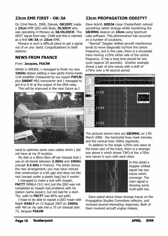
23cm PROPAGATION ODDITY?
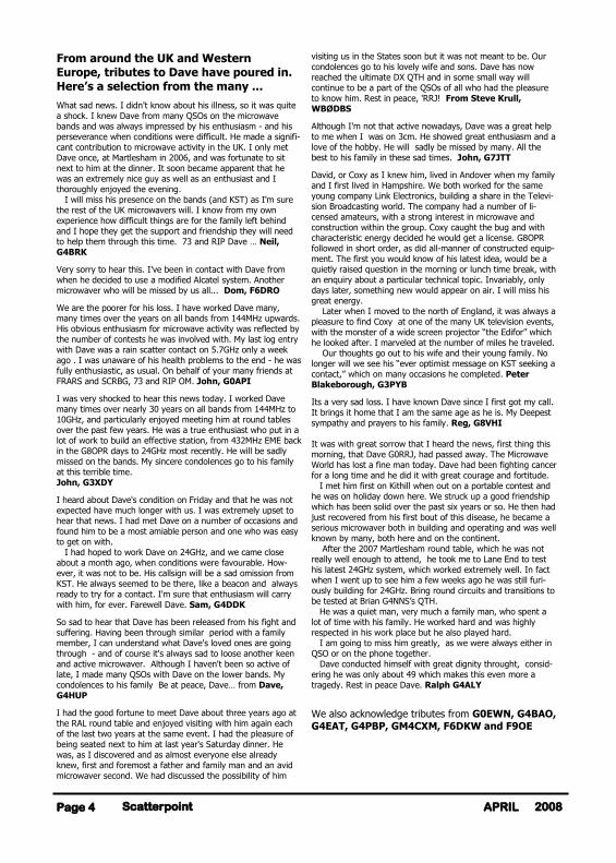
Dave Ackrill, G0DJA (near Chesterfield) noticed something rather strange whilst monitoring the GB3MHL beacon on 23cm using Spectrum Labs software. This phenomenon has occurred on a number of occasions. “Normal” Doppler shifted aircraft interference tends to move diagonally to/from the centre frequency, but in this case, there is a sinusoidal trace moving ±25Hz either side of the centre frequency. It has a long time period for one cycle (approx 20 seconds). Another example shows a pair of sine waves with a shift of ±75Hz over a 40 second period.
The pictures shown here are GB3MHL on 17th March 2008 - the horizontal lines mark minutes, and the vertical lines 100Hz segments. In addition to the single ±25Hz sine wave at the lower part of the trace, there is a stranger one above it which shows TWO of the ±75Hz sine waves in sync with each other.
In this detail a Doppler shifted signal has two traces which converge. The main signal is showing some multi-path too.
Dave asked about these strange traces on the Propagation Studies Committee reflector, and received several interesting responses. Both of them involved aircraft engine intakes.
Scatterpoint Page 18 2008 APRIL
11:03
11:04
11:05
The first from Bob, G3REP....
”when I was doing my apprenticeship at RRE Malvern >40yrs ago (RSRE now) I did some time in the Ground Radar Group. They were using a Doppler radar to lock onto moving tar-gets and used a Canberra (I think it was) as the moving target. In addition to the fuselage echo they used to get two other returns which used to be called engine sidebands coming off the turbine blades. Most of the time they were the same freq ± of the main return and dependent on engine revs as far as one could see in the 50Hz filters (again from memory) but sometimes they were differ-ent and this was put down to the different speeds of the two turbines..”
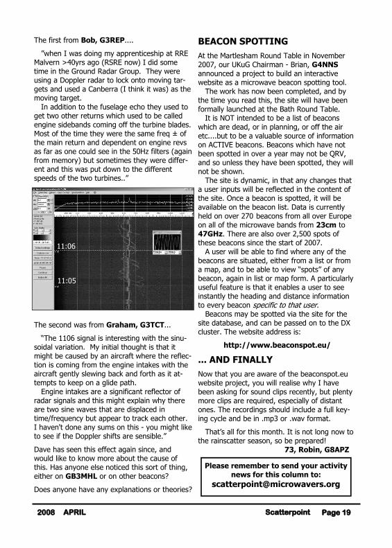
The second was from Graham, G3TCT...
“The 1106 signal is interesting with the sinu-soidal variation. My initial thought is that it might be caused by an aircraft where the reflec-tion is coming from the engine intakes with the aircraft gently slewing back and forth as it at-tempts to keep on a glide path. Engine intakes are a significant reflector of radar signals and this might explain why there are two sine waves that are displaced in time/frequency but appear to track each other. I haven't done any sums on this - you might like to see if the Doppler shifts are sensible.”
Dave has seen this effect again since, and would like to know more about the cause of this. Has anyone else noticed this sort of thing, either on GB3MHL or on other beacons?
Does anyone have any explanations or theories?
BEACON SPOTTING
At the Martlesham Round Table in November 2007, our UKuG Chairman - Brian, G4NNS announced a project to build an interactive website as a microwave beacon spotting tool. The work has now been completed, and by the time you read this, the site will have been formally launched at the Bath Round Table. It is NOT intended to be a list of beacons which are dead, or in planning, or off the air etc....but to be a valuable source of information on ACTIVE beacons. Beacons which have not been spotted in over a year may not be QRV, and so unless they have been spotted, they will not be shown. The site is dynamic, in that any changes that a user inputs will be reflected in the content of the site. Once a beacon is spotted, it will be available on the beacon list. Data is currently held on over 270 beacons from all over Europe on all of the microwave bands from 23cm to 47GHz. There are also over 2,500 spots of these beacons since the start of 2007. A user will be able to find where any of the beacons are situated, either from a list or from a map, and to be able to view “spots” of any beacon, again in list or map form. A particularly useful feature is that it enables a user to see instantly the heading and distance information to every beacon specific to that user. Beacons may be spotted via the site for the site database, and can be passed on to the DX cluster. The website address is:
http://www.beaconspot.eu/
... AND FINALLY
Now that you are aware of the beaconspot.eu website project, you will realise why I have been asking for sound clips recently, but plenty more clips are required, especially of distant ones. The recordings should include a full key-ing cycle and be in .mp3 or .wav format.
That’s all for this month. It is not long now to the rainscatter season, so be prepared! 73, Robin, G8APZ
Page 19 Scatterpoint 2008 APRIL
11:05
11:06
Please remember to send your activity news for this column to:
Scatterpoint Page 20 2008 APRIL
Microwaves from the Emerald Isle
From: Tony Gallagher EI4GHB[mailto:[email protected]] Sent: Mon 24 March 2008
I contacted UKuG some time back regard-ing getting up and running on 10GHz in Ireland. Just to let you all know, myself and two other friends have ordered 3 Downeast Microwave transverters for use on 10GHz. As there is no activity on 10GHz here in Ireland (other than an occasional Dxpedi-tion from the UK!.. editor) I'm hoping to work some UK stations. Thanks a million, in advance ..
Tony Gallagher EI4GHB Limerick, EI
http://www.freewebs.com/ei4ghb/
GB3CAM From: Bernie, G4HJW <[email protected]>
19 Mar 2008
We are still 'on' for getting both the 10GHz and 24 GHz beacons up on the Maddingley mast by the end of April (though John G4BAO wants to give the oscillator time to settle down,and may delay the 24GHz switch-on). On Thursday, I shall swap over the 10GHz beacon with the spare to allow some final tweaking with the main beacon unit. The fre-quency of the stand-by unit is the correct 10368.755MHz, so anyone monitoring will notice a 6kHz HF shift (transmitting from Ian's G4AKD, and using his call-sign). I'm currently feeding the standby unit into a TIM0910-4 amplifier and feeding that through 37m of LCF12-50 J. Output from the coax is 350mW, so that's about 1.5/2dB down on what we are licensed for but it's fine for the switch-on, I think. After 15 months of planning, we are nearly there....
73 Bernie G4HJW
SHEFFIELD MICROWAVE ROUNDTABLE … REMINDER! Just a further reminder about this event which will consist of a Saturday Intermediate Workshop (at a level one up from the beginners' workshops held over the past two years) followed by the usual "microwave round table" convention on the Sunday. You can access further details at:
http://www.microwavers.org/files/Sheffield-Microwaves.pdf
The weekend was set up as a result of popular demand for a northern microwave meeting. The success of this event depends to a large extent on YOU! I have set it up with the co-operation of my local radio radio club but it won't take off unless
(a) A lot more of you register as soon as possible. (b) there are some offers of talks for the Sunday.
Regarding (a): To date, I have a list only 9 people who say they would come along for either the whole weekend or one of the two days. I have offered to arrange accommodation in a local hotel but I can't yet approach a suitable hotel until I have some idea of how many might need a room. I might be able to get a reduced room rate if enough people sign up very soon, otherwise some of you may have to sort out your own accommodation from a list of nearby hotels that I can provide.
I also want to organise an informal dinner on the Saturday evening. Again, I need a much more positive response soon if I am to approach the management of a local hotel to set this up.
Things are not made easier by the fact that June-August is "wedding season" ! Many of the local hotels (and even motels) are already booked up for that weekend and the one I have in mind could very well be so within a week or two.
So, PLEASE REGISTER WITH ME NOW! All I need is an email with your name, callsign, phone number, which days you wish to attend, whether or not you need accommoda-tion and whether or not you want to attend the microwave workshop. Once I have your intention to attend I will send you further details of accommodation, access, etc.
Regarding (b): I have all the help and demonstrations I need for the Intermediate Workshop but I urgently need more speakers for the Sunday "Round Table". Please email me ASAP soon if you are able to give a talk on any-thing of microwave interest.
Finally, I will be away in VK/ZL for a full month between now and the event so I really need you to respond as soon as possible if I am to set up accommodation for you before the wedding parties take over the rooms! 73 Peter, G3PHO