Embed Size (px)
Citation preview

Kedrick Black 1
ECE 5320 MechatronicsAssignment #1
Torque Coils/Rods and Reaction WheelsKedrick Black

Kedrick Black 2
Outline
• Sensor/Actuator/Operation Interface• Explanation of Attitude Control• External Disturbances• Reaction Wheels• Torque coils/rods• Design optimization• Momentum dumping• Places to buy/cost

Kedrick Black 3
References
• Space Mission Analysis And Design• http://uasat.arizona.edu/http://uasat.arizona.edu/• http://fuse.pha.jhu.edu/educ/RW_FAQ.htmhttp://fuse.pha.jhu.edu/educ/RW_FAQ.htm• www.mae.usu.edu/faculty/tmosher/classeswww.mae.usu.edu/faculty/tmosher/classes

Kedrick Black 4
To Explore Further(web pointers)
• http://staff.ee.sun.ac.za/whsteyn/Papers/Magsat.pdf• http://ocw.mit.edu/NR/rdonlyres/Aeronautics-and-Astronautics/ 16-358JSystem-SafetySpring2003/B169A368-9DCC-4916-8897-12B0DE4DC855/ 0/hete.pdf• http://ocw.mit.edu/NR/rdonlyres/Mechanical-Engineering/2-141Fall-2002/4706270A- 4F69-4020-958A-F5172054F35F/0/dcpmm_basics.pdf

Kedrick Black 5
Credit: www.ocw.mit.edu
Sensor/Actuator/Operation Interface
Credit: ECE 5320 class slides

Kedrick Black 6
Attitude Control
• The system that turns and maintains a spacecraft in the required direction as indicated by its sensors.• Spacecraft subsystem capable of pointing the spacecraft toward a selected target. • Stabilizing a satellite's attitude (direction) in its orbit. Attitude control can be done by spinning the satellite, or by having it remain stabilized in three axes using an internal mechanism such as reaction wheels and/or torque coils/rods.

Kedrick Black 7
Attitude Control Parameters
Kedrick Black 8
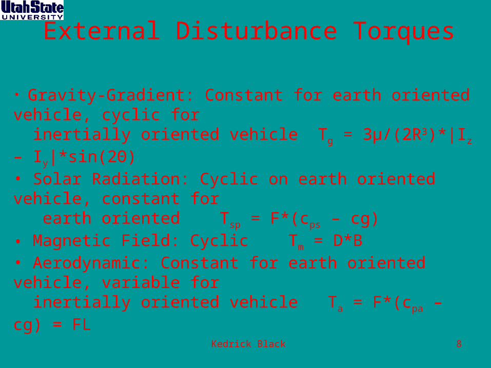
External Disturbance Torques
• Gravity-Gradient: Constant for earth oriented vehicle, cyclic for inertially oriented vehicle Tg = 3μ/(2R3)*|Iz – Iy|*sin(2Θ)• Solar Radiation: Cyclic on earth oriented vehicle, constant for earth oriented Tsp = F*(cps – cg)• Magnetic Field: Cyclic Tm = D*B• Aerodynamic: Constant for earth oriented vehicle, variable for inertially oriented vehicle Ta = F*(cpa – cg) = FL

Kedrick Black 9
Reaction Wheels
• Used to hold the spacecraft steady or to move from one pointing direction to another• spinning flywheel mounted on a central bearing whose rate of rotation can be adjusted as necessary by an electric motor to apply a force and move the spacecraft• any change in the rate of spin of these wheels creates a predictable force that nudges the satellite's pointing direction • Once in position, very tiny changes in spin rates work to keep us pointing at the object of interest

Kedrick Black 10
Reaction Wheel sizing equationsand performance ranges
• Momentum Storage (h): h = TD*(Orbital Period/4)*(0.707)• Slew Torque: Θ/2 = (1/2)*(T/I)*(t/2)2 • 0.4 to 400 Nms @ 1200 to 1500 rpm• 2 to 20kg• 10 to 110W

Kedrick Black 11
-3
10 200 400 600 800 1000 1200
-1
0
1x 10
0 200 400 600 800 1000 1200-1
0
0 200 400 600 800 1000 1200-1
0
1
0 200 400 600 800 1000 1200-1
0
1
Time (s)
Rea
ctio
n W
heel
Tor
ques
(N
m)
Reaction wheel torques
Credit: University of Arizona

Kedrick Black 12
0 200 400 600 800 1000 12000
100
200
300
400
500
600
700
800
900
1000
Time (s)
Rea
ctio
n W
heel
Spe
eds
(rpm
)
Reaction wheel speeds
Credit: University of Arizona

Kedrick Black 13
• Light Weight - assemblies as light as 0.3 lbs • Anomaly Free Operation • Retainerless Bearing - eliminates most failure modes • Operates in a Vacuum - no seals, no pressure housing • High Speed Capable - up to 100,000 rpm • Energy - up to 400,000 ft.lbs • Diameter - 0.2 to 15.5 inches and above • Thermal Changes - zero • Radial Runout - less than 1 millionth of an inch • Bearing Life -226 years for microsats
VFCT Reaction Wheel

Kedrick Black 14

Kedrick Black 15
Torque coils vs. Rods
•Coils - Simpler than torque rodsSimpler than torque rods - Least costly option- Least costly option - Linear response to input current simplifies - Linear response to input current simplifies control requirementscontrol requirements - Possible issues with stray magnetic fields- Possible issues with stray magnetic fields•RodsRods - Most efficient option- Most efficient option - Easier to implement- Easier to implement - Hard to find appropriate core material- Hard to find appropriate core material

Kedrick Black 16
0a
NR
0aNM
222
AM
mRiP
Aa
mV
0
AM
ami
0
0Naa
432
• Power, current, voltage and resistance:
• Mass and wire size:
• Moment equation:
Coil Design Formulas

Kedrick Black 17
mas
s [k
g]
Power [watts]
Total mass vs.Power consumption
Design Optimization
Specifications -Dipole moment of 5 Am2 -Power consumption of
0.3 W (16 mA at 20 V) -Uses 32 gauge square magnet wire -Total mass of 3 kg

Kedrick Black 18
Credit: University of Arizona
Mounting Possibilities
•Two ideas -Designed to fit within side beam -Wrapped into groove on exterior of satellite•Three coils form mutually perpendicular axes

Kedrick Black 19
Momentum Dumping
• Presence of torque on spacecraft at all times causes wheels to spin at all times• Momentum builds up and needs to be dumped• The approach is to consider both the need and efficiency of dumping at a particular time.• Torque coils/rods are a good solution

Kedrick Black 20
Places to buy/Cost
Reaction Wheels• Bendix• Honeywell• cost approx. $5000.00
Torque Coils• Ithaco• Hughes• Lockheed• McDonnell Douglas• cost approx. $2000.00


![Public PM800 Register List 11.9xx - Contemporary Controls[5320] Trending & Forecasting Configuration (5320 - 5369) 84 Trending & Forecasting Standard Quantities 84 [5370] Alarm Summary](https://img.pdfslide.us/doc/110x75/5e839b0cd7792e3a9468047f/public-pm800-register-list-119xx-contemporary-controls-5320-trending-.jpg)