Embed Size (px)
Citation preview
KeContact P20 Installation manual
(for the specialist)
© KEBA 2012-2013 Specifications are subject to change due to ongoing technical development. No guarantee is offered in respect of any of the specifications given here. All rights reserved. All intellectual property, including trademarks and copyrights are the property of their respective owners. Any unauthorized use thereof is strictly prohibited.
Document: Version 1.41 / Article no.: 90064
KEBA AG, Postfach 111, Gewerbepark Urfahr, A-4041 Linz
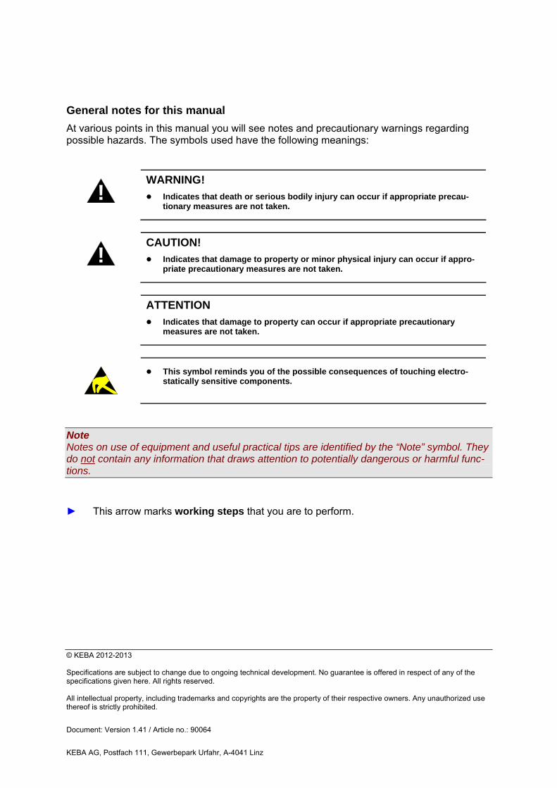
General notes for this manual
At various points in this manual you will see notes and precautionary warnings regarding possible hazards. The symbols used have the following meanings:
!
WARNING!
Indicates that death or serious bodily injury can occur if appropriate precau-tionary measures are not taken.
!
CAUTION!
Indicates that damage to property or minor physical injury can occur if appro-priate precautionary measures are not taken.
ATTENTION
Indicates that damage to property can occur if appropriate precautionary measures are not taken.
This symbol reminds you of the possible consequences of touching electro-statically sensitive components.
Note Notes on use of equipment and useful practical tips are identified by the “Note” symbol. They do not contain any information that draws attention to potentially dangerous or harmful func-tions.
► This arrow marks working steps that you are to perform.
KeContact P20 Contents
Installation manual, Version: 1.41 / Article no.: 90064 3
© KEBA 2012-2013
KeContact P20 bears the CE mark.
The corresponding Declarations of Conformity are located at KEBA AG.
This product meets the requirements of the ROHS Directive (2011/65/EU).
The corresponding Declaration of Conformity is located at KEBA AG.
Disposal information
The crossed-out trash container symbol indicates that electric appliances and electronic devices including accessories are to be disposed of separately from general household trash. You can find more information about this directly on the product, in the operating manual or on the packaging. The materials are recyclable according to their labeling. You can make an important contri-bution to protecting our environment by reusing, renewing and recycling materials and old appliances.
Revision history Modification
from / to Date modified
Pages Description
V1.41 040613 - Manual revised
Contents KeContact P20
4 Installation manual, Version: 1.41 / Article no.: 90064
© KEBA 2012-2013
Contents
1 Important information.................................................................................................................... 5
1.1 Safety instructions................................................................................................................. 5 1.2 Intended use.......................................................................................................................... 7 1.3 About this manual ................................................................................................................. 7 1.4 Product description ............................................................................................................... 8
2 Overview ......................................................................................................................................... 9
2.1 Variant overview.................................................................................................................... 9 2.2 Optional equipment ............................................................................................................. 10
2.2.1 RFID sensor.......................................................................................................... 10 2.2.2 Key switch............................................................................................................. 10 2.2.3 Additional optional equipment............................................................................... 11
3 Installation guidelines ................................................................................................................. 12
3.1 General criteria for the site selection .................................................................................. 12 3.2 Specifications for the electrical connection ......................................................................... 13 3.3 Space requirements ............................................................................................................ 14
4 Installation .................................................................................................................................... 15
4.1 Preparing the housing ......................................................................................................... 17 4.1.1 Removing the housing cover ................................................................................ 17 4.1.2 Removing/mounting the connector panel cover ................................................... 18
4.2 Preparing the cable insertion .............................................................................................. 19 4.2.1 Cable insertion from above - surface cable routing.............................................. 20 4.2.2 Cable insertion from behind - flush-type cable routing ......................................... 20
4.3 Mounting the charging station............................................................................................. 21 4.4 Electrical connection ........................................................................................................... 24
4.4.1 Connection overview with opened connector panel cover ................................... 24 4.4.2 Connecting the mains supply line ......................................................................... 25 4.4.3 Enable input [X1]................................................................................................... 28 4.4.4 Switch contact output [X2] .................................................................................... 29 4.4.5 Terminals [X1/X2] ................................................................................................. 30 4.4.6 Ethernet1 connection [ETH] (optional) ................................................................. 30
4.5 DIP-switch settings.............................................................................................................. 33 4.6 Commissioning.................................................................................................................... 37
4.6.1 Commissioning mode/self test.............................................................................. 38 4.6.2 Safety checks........................................................................................................ 39 4.6.3 Mounting the housing cover.................................................................................. 40
5 Further technical instructions .................................................................................................... 41
5.1 Programming RFID cards (optional) ................................................................................... 41 5.2 Configure the communication with the EV PLC->Ethernet (optional)................................. 42 5.3 Replacing the fuse .............................................................................................................. 42 5.4 Dimensions.......................................................................................................................... 43 5.5 Technical data..................................................................................................................... 44 5.6 Standards and regulations .................................................................................................. 46
6 INDEX ............................................................................................................................................ 47
KeContact P20 Important information
Installation manual, Version: 1.41 / Article no.: 90064 5
© KEBA 2012-2013
1 Important information
1.1 Safety instructions
!
WARNING!
Not observing the safety instructions can result in risk of death, injuries and dam-age to the device! KEBA AG assumes no liability for claims resulting from this!
Electrical hazard! The installation, commissioning and maintenance of the charging station may only be performed by correctly trained, qualified and authorized electricians who are fully responsible for the compliance with existing standards and in-stallation regulations. Please observe that an additional overvoltage protection of vehicles or national regulations can be required. Also observe that some countries or vehicle manufacturers may require a dif-ferent triggering characteristic of the fault-current circuit breaker (Type B).
Only connect voltages and circuits in the right-hand connection area (Ethernet, terminals for control lines) that have a secure separation to dangerous volt-ages (e.g. sufficient isolation). Only supply the terminals (X2) from voltage sources which feature safety extra-low voltage!
Before commissioning, check all screw and terminal connections for firm seat-ing!
The connector panel cover may never be left open unattended. Mount the con-nector panel cover if you leave the charging station.
Do not carry out any unauthorized conversion work or modifications to the charging station!
Repair work to the charging station is not permitted and may only be per-formed by the manufacturer (replacement of the charging station)!
Do not remove any notices on the device, such as safety symbols, warning notices, rating plates, nameplates or cable markings!
The charging station does not have its own power switch! The RCD circuit breaker and the line circuit breaker of the building installation serve as mains disconnector.
Observe the instructions given for selecting the location and the construc-tional requirements! If the specifications for the location are not observed, this can result in death, serious physical injury or equipment damage if the corresponding precaution-ary measures are not met!
Important information KeContact P20
6 Installation manual, Version: 1.41 / Article no.: 90064
© KEBA 2012-2013
!
WARNING!
Pull the charging cable only at the plug and not at the cable out of the connec-tor.
Ensure that the charging cable is not mechanically damaged (bent, pinched or run over) and the connection area does not come into contact with heat sources, dirt or water.
5 safety rules:
- Shut down all poles and all sides! - Secure against reactivation! - Check that the equipment is voltage-free! - Ground and short-circuit! - Cover adjacent live parts and restrict access to hazardous areas!
ATTENTION
Risk of damage! Make sure that the charging station is not damaged by improper handling (an-choring, housing cover, socket, inner parts etc.).
Do not open the connector panel cover in the rain!
Risk of breaking the plastic housing! - Countersunk screws may not be used for the mounting! - The included washers must be used. - Do not tighten the mounting screws with force. - The mounting surface must be completely level (max. 1 mm difference be-tween the support points or mounting points). Warpage of the housing must be prevented.
Information for technicians who are permitted to open the device:
Risk of damage! Electronic components can be destroyed if touched! Before handling components, make sure you perform an electrical discharge by touching a metallic, grounded object!
KeContact P20 Important information
Installation manual, Version: 1.41 / Article no.: 90064 7
© KEBA 2012-2013
1.2 Intended use
KeContact P20 is a "charging station" for the indoor and outdoor area at which electrically operated vehicles can be charged (e.g. electric automobiles).
The charging station is designed for installation on a wall or in a floor-mounted column.
The respective national regulations must be observed with regard to the installation and con-nection of the charging station.
The intended use of the device always includes the compliance with the environmental con-ditions for which this device was developed.
The device was developed, manufactured, inspected and documented in compliance with the relevant safety standards. Therefore, the products do not pose any danger to the health of persons or a risk of damage to other property or equipment under normal circumstances, provided that the instructions and safety precautions relating to the intended use are properly observed.
The instructions contained in this manual must be followed precisely in all circumstances. Failure to do so could result in the creation of potential sources of danger or the disabling of safety devices. Apart from the safety instructions given in this manual, the safety precautions and accident prevention measures appropriate to the situation in question must also be ob-served.
Only electrical vehicles or their chargers may be connected. A connection of other loads (e.g. electric tools) is not permitted!
Due to technical or legal restrictions, not all variants / options are available in all countries.
1.3 About this manual
This manual is valid for devices of the type KeContact P20
Use of this manual This installation manual is intended for qualified personnel only1.
The figures and explanations contained in this manual refer to a typical device design. The design of the device may deviate from it.
Please refer to the "KeContact P20 User manual" for information and instructions about op-erating the device.
1 Persons who, due to their special training, expertise, and experience, as well as knowledge of current standards, are able to assess the work performed and the possible hazards.
Important information KeContact P20
8 Installation manual, Version: 1.41 / Article no.: 90064
© KEBA 2012-2013
1.4 Product description
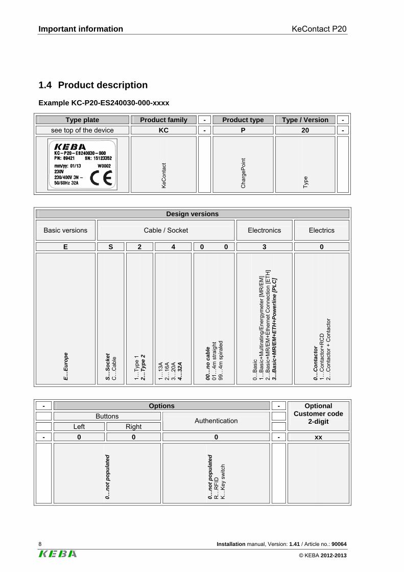
Example KC-P20-ES240030-000-xxxx
Type plate Product family - Product type Type / Version -
see top of the device KC - P 20 -
KeC
onta
ct
Cha
rgeP
oint
Typ
e
Design versions
Basic versions Cable / Socket Electronics Electrics
E S 2 4 0 0 3 0
E…
Eu
rop
e
S…
So
cket
C
…C
able
1…T
ype
1 2…
Ty
pe
2
1…13
A
2…16
A
3…20
A
4…32
A
00…
no
cab
le
01…
4m s
trai
ght
99…
4m s
pira
led
0...
Bas
ic
1...
Bas
ic+
Mul
tirat
ing/
Ene
rgym
eter
[MR
/EM
] 2.
..Bas
ic+
MR
/EM
+E
ther
net C
on
nect
ion
[ET
H]
3...B
asic
+M
R/E
M+
ET
H+
Po
wer
lin
e [P
LC
]
0…C
on
tac
tor
1…C
onta
cto
r+R
CD
2…
Con
tact
or
+ C
onta
ctor
- Options -
Buttons
Left Right Authentication
Optional Customer code
2-digit
- 0 0 0 - xx
0…n
ot
po
pu
late
d
0…n
ot
po
pu
late
d
R…
RF
ID
K…
Key
sw
itch
KeContact P20 Overview
Installation manual, Version: 1.41 / Article no.: 90064 9
© KEBA 2012-2013
2 Overview
2.1 Variant overview
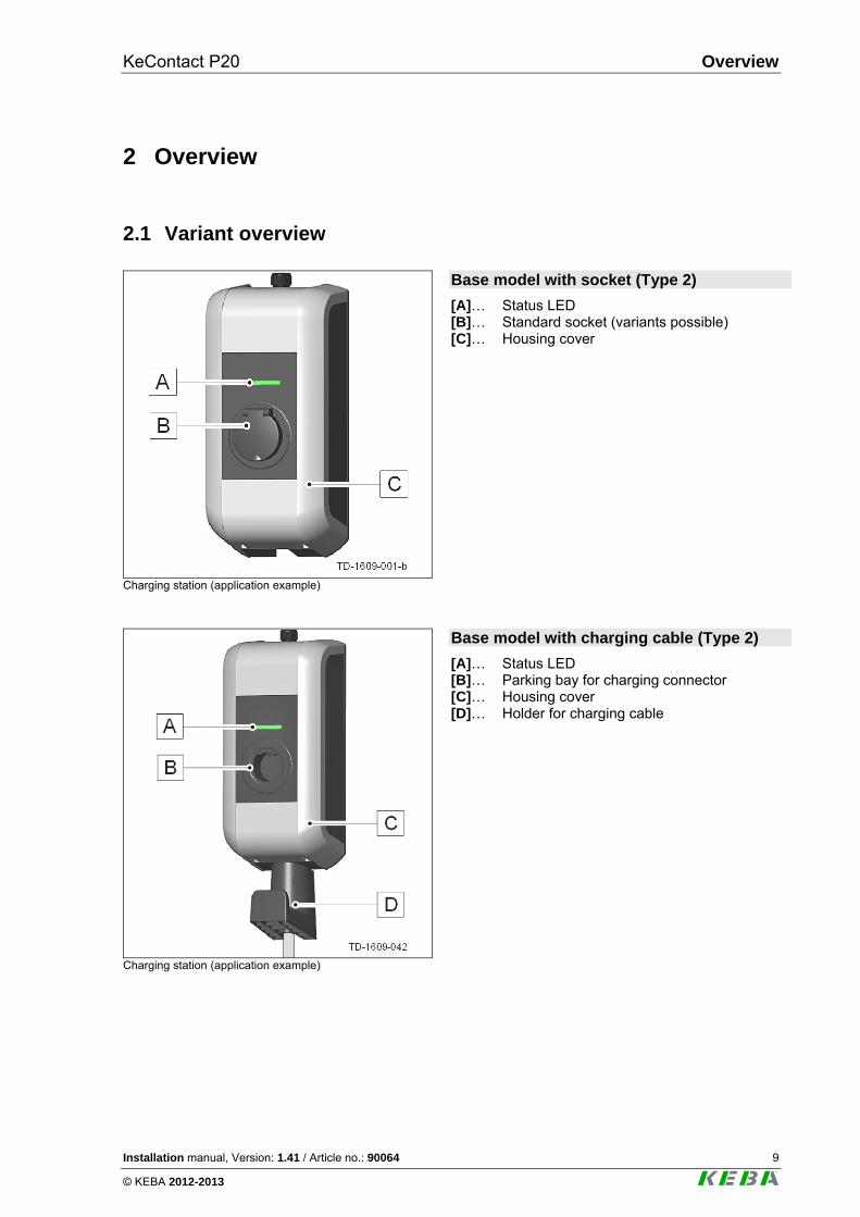
Charging station (application example)
Base model with socket (Type 2)
[A]… Status LED [B]… Standard socket (variants possible) [C]… Housing cover
Charging station (application example)
Base model with charging cable (Type 2)
[A]… Status LED [B]… Parking bay for charging connector [C]… Housing cover [D]… Holder for charging cable
Overview KeContact P20
10 Installation manual, Version: 1.41 / Article no.: 90064
© KEBA 2012-2013
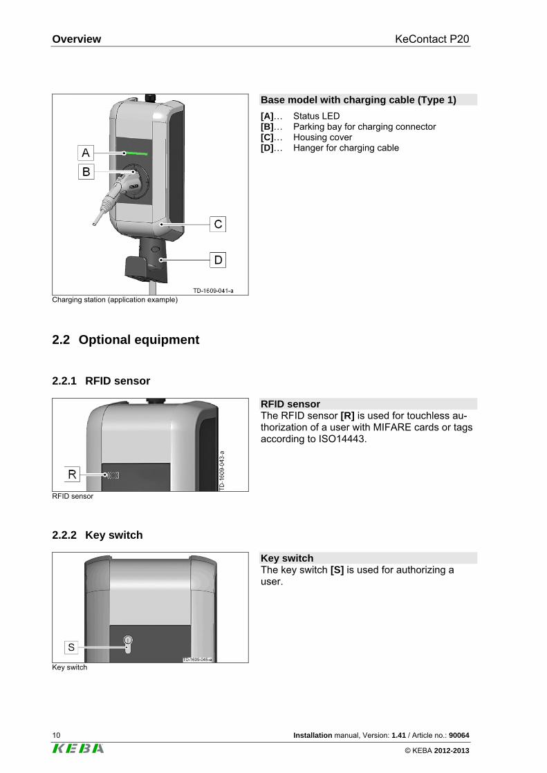
Charging station (application example)
Base model with charging cable (Type 1)
[A]… Status LED [B]… Parking bay for charging connector [C]… Housing cover [D]… Hanger for charging cable
2.2 Optional equipment
2.2.1 RFID sensor
RFID sensor
RFID sensor The RFID sensor [R] is used for touchless au-thorization of a user with MIFARE cards or tags according to ISO14443.
2.2.2 Key switch
Key switch
Key switch The key switch [S] is used for authorizing a user.
KeContact P20 Overview
Installation manual, Version: 1.41 / Article no.: 90064 11
© KEBA 2012-2013
2.2.3 Additional optional equipment
Network capability Switch contact (for control of external additional equipment e.g. fan) Enable input for e.g. ripple control receivers, time switches,…
This permits a scheduled (time-controlled) charging of the vehicle to be realized. PLC (Power Line Communication) according to GreenPhy standard Mounting column

Installation guidelines KeContact P20
12 Installation manual, Version: 1.41 / Article no.: 90064
© KEBA 2012-2013
3 Installation guidelines
3.1 General criteria for the site selection
The charging station was constructed for the indoor and outdoor area. Accordingly, it is nec-essary to ensure the installation conditions and the protection of the device at the installation site.
Take into account the local electrical installation regulations, fire prevention measures and accident prevention regulations as well as emergency routes at this site.
The charging station must not be installed in potentially explosive zones (EX environ-ment).
Mount the charging station so that it is not located in the direct flow of passersby and so that no one can trip over connected charging cables and so that the charging cables do not cover or cross passing pedestrian and motorized traffic.
Do not install the charging station at locations where ammonia or ammonia gas is ex-posed (e.g. in or at stables).
The mounting surface must be sufficiently constructed in order to withstand the mechani-cal forces.
Do not mount the charging station at locations where falling objects (e.g. hung ladders or automobile tires) could damage the device.
According to the product standard, the charging station must be located at a height be-tween 0.4 m and 1.5 m. We recommend mounting the charging station (height of the socket or parking bay) at a height of 1.2 m. Observe that national regulations can limit this height.
The device may not be exposed to direct spray water (by e.g. neighboring manual car-wash facility, high-pressure cleaner, garden hose).
If possible, the device should be mounted protected from direct rainfall, in order to avoid e.g. icing, damage because of hail or similar.
If possible, the charging station should be mounted protected from direct sunlight, in or-der to avoid the reduction of the charging current or the interruption of the charging pro-cedure due too high temperatures of the components inside the charging station.
For not weatherproof mounting (e.g. in a parking lot outside), the charging current setting is changed to 16A, if the temperature is inadmissible exceeded. Subsequently, the charg-ing process can also be switched off.
For information about environmental conditions, please refer to the "Technical Data" chapter.
Observe the internationally relevant installation standards (e.g. IEC 60364-1 and IEC 60364-5-52) and follow the applicable national installation standards and regula-tions.
KeContact P20 Installation guidelines
Installation manual, Version: 1.41 / Article no.: 90064 13
© KEBA 2012-2013
3.2 Specifications for the electrical connection
General The charging station is set to 10 amps in the delivery state. Set the maximum EVSE current capacity by setting the DIP-switches in coordination with your installed line circuit breaker (see chapter “DIP-switch settings”). The mains supply line must be hardwired to an existing house installation and correspond to the nationally applicable legal conditions.
Selection of the RCD circuit breaker:
Each charging station must be connected to a separate RCD circuit breaker. No other circuits may be connected to this RCD circuit breaker.
RCD circuit breaker of at least Type A In derogation with this, a RCD circuit breaker Type B can be a requirement by the ve-hicle manufacturer. If the electric vehicles are not known (e.g., semi-public area), the use of an RCD circuit breaker Type B is useful.
The nominal current IN must be selected to match the line circuit breaker and the fuse.
Dimensioning the Line circuit breaker: When dimensioning the line circuit breaker also observe the increased environmental tem-peratures in the switching cabinet! Under certain circumstances, this may require a reduction of the preadjusted charging current setting to increase the system availability.
Maximum value according to the type plate data matching to the DIP-switch settings of the preadjusted charging current value.
Determine the nominal current in accordance with the specifications on the type plate, in coordination with the desired charging current (DIP switch settings for the pre-adjusted maximum EVSE current capacity) and the mains supply line.
Dimensioning of the mains supply line:
When dimensioning the mains supply line also observe possible reduction factors and the increased environmental temperatures in the interior connection area of the charging station (see „Mains supply terminals temperature rating”)! Under certain circumstances, this can lead to an increase of the cable cross-section and to the adaptation of the temperature resis-tance of the mains supply line. Mains disconnector:
The charging station does not have its own power switch. The RCD circuit breaker and the line circuit breaker of the mains supply line serve as mains disconnector.
Installation guidelines KeContact P20
14 Installation manual, Version: 1.41 / Article no.: 90064
© KEBA 2012-2013
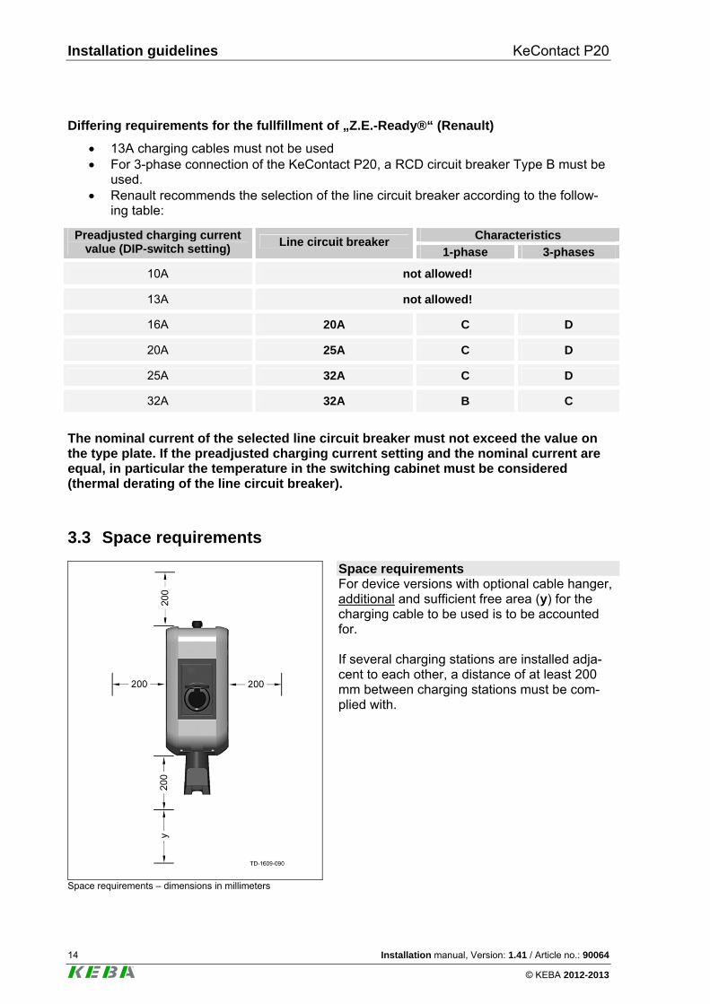
Differing requirements for the fullfillment of „Z.E.-Ready®“ (Renault)
13A charging cables must not be used For 3-phase connection of the KeContact P20, a RCD circuit breaker Type B must be
used. Renault recommends the selection of the line circuit breaker according to the follow-
ing table:
Characteristics Preadjusted charging current value (DIP-switch setting)
Line circuit breaker 1-phase 3-phases
10A not allowed!
13A not allowed!
16A 20A C D
20A 25A C D
25A 32A C D
32A 32A B C
The nominal current of the selected line circuit breaker must not exceed the value on the type plate. If the preadjusted charging current setting and the nominal current are equal, in particular the temperature in the switching cabinet must be considered (thermal derating of the line circuit breaker).
3.3 Space requirements
Space requirements – dimensions in millimeters
Space requirements For device versions with optional cable hanger, additional and sufficient free area (y) for the charging cable to be used is to be accounted for. If several charging stations are installed adja-cent to each other, a distance of at least 200 mm between charging stations must be com-plied with.
KeContact P20 Installation
Installation manual, Version: 1.41 / Article no.: 90064 15
© KEBA 2012-2013
4 Installation
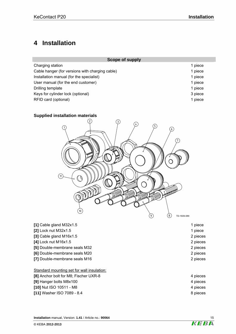
Scope of supply
Charging station 1 piece
Cable hanger (for versions with charging cable) 1 piece
Installation manual (for the specialist) 1 piece
User manual (for the end customer) 1 piece
Drilling template 1 piece
Keys for cylinder lock (optional) 3 piece
RFID card (optional) 1 piece
Supplied installation materials
[1] Cable gland M32x1.5 1 piece
[2] Lock nut M32x1.5 1 piece
[3] Cable gland M16x1.5 2 pieces
[4] Lock nut M16x1.5 2 pieces
[5] Double-membrane seals M32 2 pieces
[6] Double-membrane seals M20 2 pieces
[7] Double-membrane seals M16 2 pieces
Standard mounting set for wall insulation:
[8] Anchor bolt for M8; Fischer UXR-8 4 pieces
[9] Hanger bolts M8x100 4 pieces
[10] Nut ISO 10511 - M8 4 pieces
[11] Washer ISO 7089 - 8.4 8 pieces
Installation KeContact P20
16 Installation manual, Version: 1.41 / Article no.: 90064
© KEBA 2012-2013
Installation requirements Before beginning the installation, the installation guidelines must be observed.
Contact person on-site (for access to the mains disconnector in the electrical distribution panel board).
The electrical connection (mains supply line) must be prepared.
Acclimation: With a temperature difference of more than 15°C between transport and installation site, the charging station should be acclimatized for at least an hour (preferably unopened).
The immediate opening of the charging station can lead to a formation of water in the in-side and can cause damages when switching on the device. A possible damage could also occur at a later time after installation.
Ideally, the charging station should be stored at the installation site for a few hours. If this is not possible, the charging station should not be stored outside overnight or in a vehicle at cold temperatures (<5°C).
Tool list to handle KC-P20 The following tools are required for the installation:
Flathead screwdriver for mains supply terminals (blade width 5.5 mm) Flathead screwdriver for terminals X1/X2 (blade width 3.0 mm) Phillips head screwdriver PH2 Mounting tools for cable glands M16 (width across flats 20mm) and M32 (width across
flats 36mm) LSA+ insertion tool (optional)
KeContact P20 Installation
Installation manual, Version: 1.41 / Article no.: 90064 17
© KEBA 2012-2013
4.1 Preparing the housing
4.1.1 Removing the housing cover
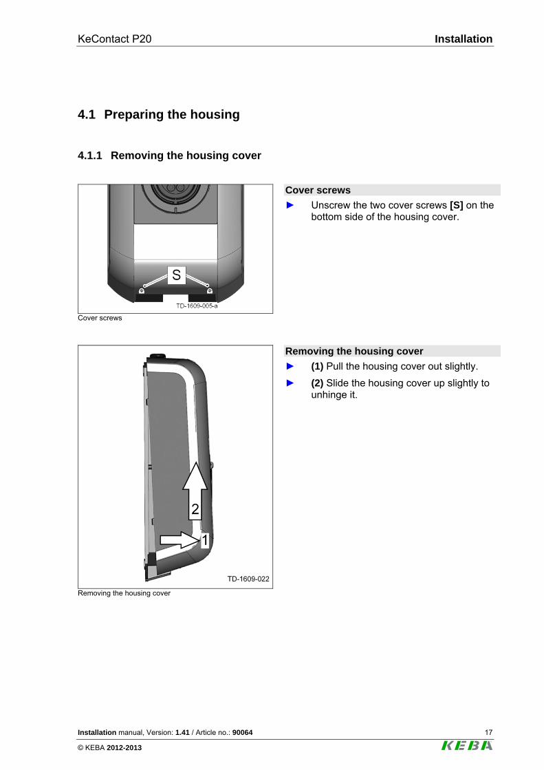
Cover screws
Cover screws
► Unscrew the two cover screws [S] on the bottom side of the housing cover.
Removing the housing cover
Removing the housing cover
► (1) Pull the housing cover out slightly.
► (2) Slide the housing cover up slightly to unhinge it.
Installation KeContact P20
18 Installation manual, Version: 1.41 / Article no.: 90064
© KEBA 2012-2013
4.1.2 Removing/mounting the connector panel cover
Removing the connector panel cover
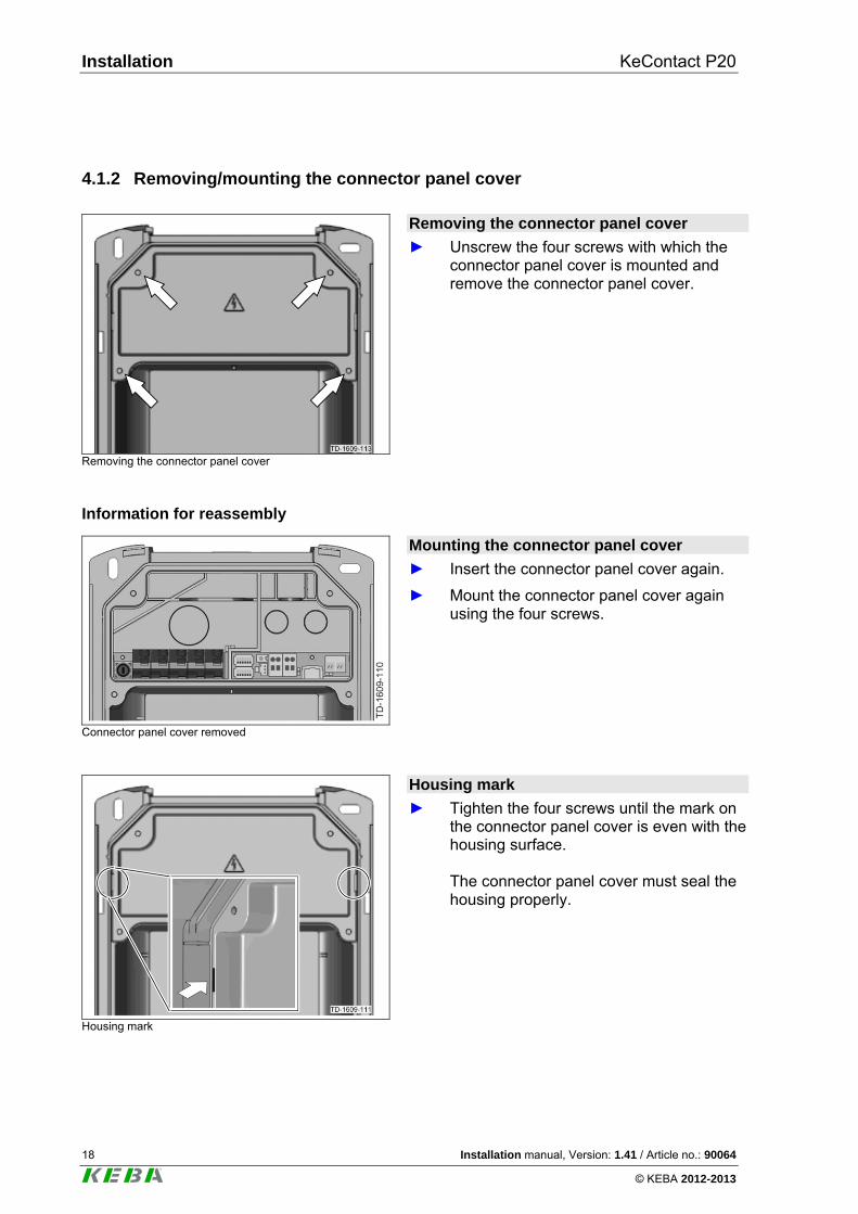
Removing the connector panel cover
► Unscrew the four screws with which the connector panel cover is mounted and remove the connector panel cover.
Information for reassembly
Connector panel cover removed
Mounting the connector panel cover
► Insert the connector panel cover again.
► Mount the connector panel cover again using the four screws.
Housing mark
Housing mark
► Tighten the four screws until the mark on the connector panel cover is even with the housing surface. The connector panel cover must seal the housing properly.
KeContact P20 Installation
Installation manual, Version: 1.41 / Article no.: 90064 19
© KEBA 2012-2013
4.2 Preparing the cable insertion
There are two possibilities available for the cable insertion:
Cable insertion from above (surface cable routing)
Cable insertion from behind (flush-type cable routing) Preparations
► Remove the connector panel cover (see Chapter "Removing/mounting the cable panel cover").
► Populate the charging station with the required cable glands or seals (if an open cable insertion opening is not used any more).
Breaking out the cable insertion openings
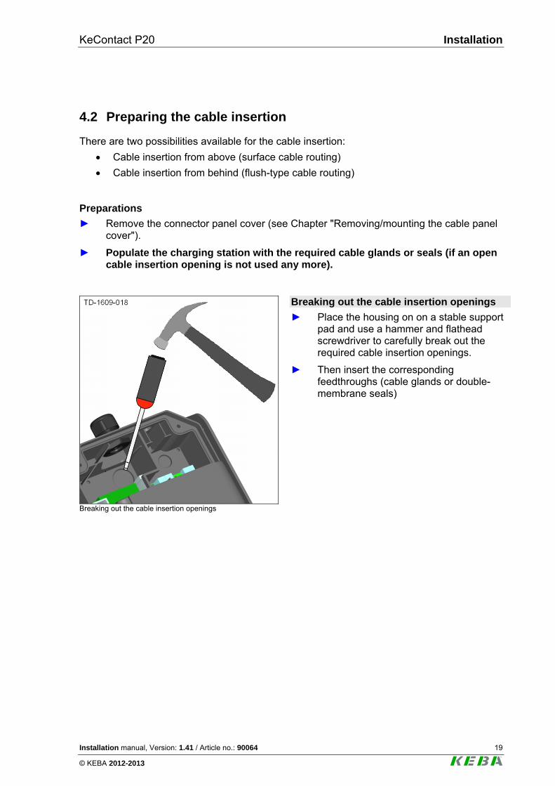
Breaking out the cable insertion openings
► Place the housing on on a stable support pad and use a hammer and flathead screwdriver to carefully break out the required cable insertion openings.
► Then insert the corresponding feedthroughs (cable glands or double-membrane seals)
Installation KeContact P20
20 Installation manual, Version: 1.41 / Article no.: 90064
© KEBA 2012-2013
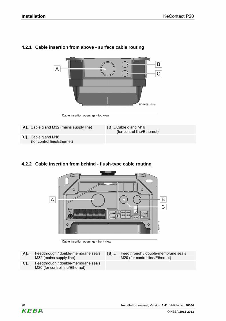
4.2.1 Cable insertion from above - surface cable routing
Cable insertion openings - top view
[A]…Cable gland M32 (mains supply line)
[B]…Cable gland M16 (for control line/Ethernet)
[C]…Cable gland M16 (for control line/Ethernet)
4.2.2 Cable insertion from behind - flush-type cable routing
Cable insertion openings - front view
[A]… Feedthrough / double-membrane seals M32 (mains supply line)
[B]… Feedthrough / double-membrane seals M20 (for control line/Ethernet)
[C]… Feedthrough / double-membrane seals M20 (for control line/Ethernet)
KeContact P20 Installation
Installation manual, Version: 1.41 / Article no.: 90064 21
© KEBA 2012-2013
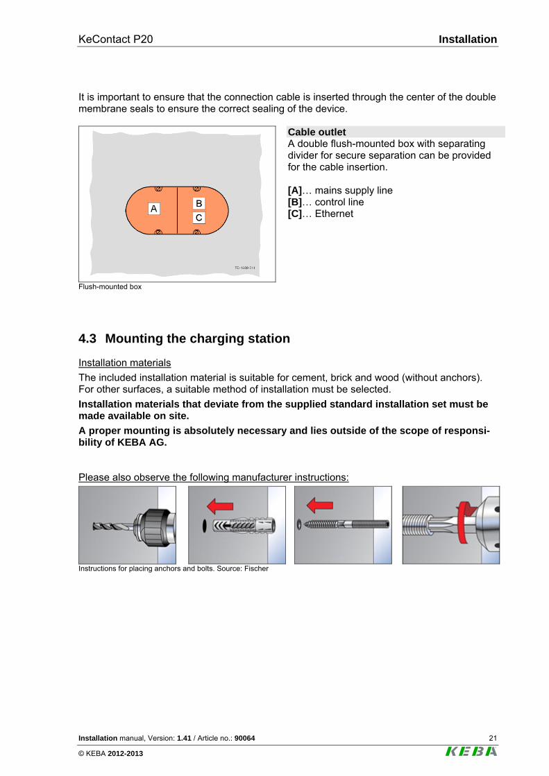
It is important to ensure that the connection cable is inserted through the center of the double membrane seals to ensure the correct sealing of the device.
Flush-mounted box
Cable outlet A double flush-mounted box with separating divider for secure separation can be provided for the cable insertion. [A]… mains supply line [B]… control line [C]… Ethernet
4.3 Mounting the charging station
Installation materials
The included installation material is suitable for cement, brick and wood (without anchors). For other surfaces, a suitable method of installation must be selected.
Installation materials that deviate from the supplied standard installation set must be made available on site.
A proper mounting is absolutely necessary and lies outside of the scope of responsi-bility of KEBA AG. Please also observe the following manufacturer instructions:
Instructions for placing anchors and bolts. Source: Fischer
Installation KeContact P20
22 Installation manual, Version: 1.41 / Article no.: 90064
© KEBA 2012-2013
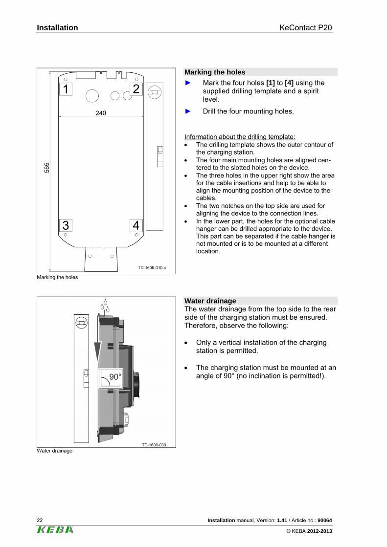
Marking the holes
Marking the holes
► Mark the four holes [1] to [4] using the supplied drilling template and a spirit level.
► Drill the four mounting holes. Information about the drilling template: The drilling template shows the outer contour of
the charging station. The four main mounting holes are aligned cen-
tered to the slotted holes on the device. The three holes in the upper right show the area
for the cable insertions and help to be able to align the mounting position of the device to the cables.
The two notches on the top side are used for aligning the device to the connection lines.
In the lower part, the holes for the optional cable hanger can be drilled appropriate to the device. This part can be separated if the cable hanger is not mounted or is to be mounted at a different location.
Water drainage
Water drainage The water drainage from the top side to the rear side of the charging station must be ensured. Therefore, observe the following: Only a vertical installation of the charging
station is permitted. The charging station must be mounted at an
angle of 90° (no inclination is permitted!).
KeContact P20 Installation
Installation manual, Version: 1.41 / Article no.: 90064 23
© KEBA 2012-2013
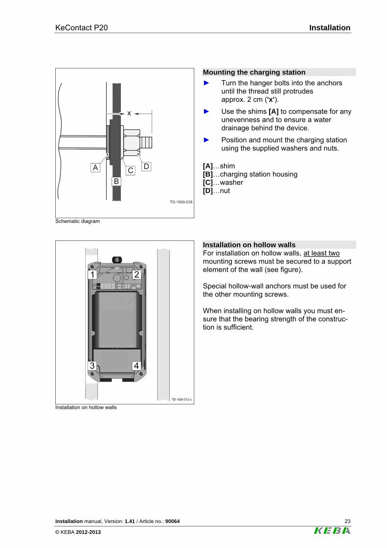
Schematic diagram
Mounting the charging station
► Turn the hanger bolts into the anchors until the thread still protrudes approx. 2 cm ('x').
► Use the shims [A] to compensate for any unevenness and to ensure a water drainage behind the device.
► Position and mount the charging station using the supplied washers and nuts.
[A]…shim [B]…charging station housing [C]…washer [D]…nut
Installation on hollow walls
Installation on hollow walls For installation on hollow walls, at least two mounting screws must be secured to a support element of the wall (see figure). Special hollow-wall anchors must be used for the other mounting screws. When installing on hollow walls you must en-sure that the bearing strength of the construc-tion is sufficient.
Installation KeContact P20
24 Installation manual, Version: 1.41 / Article no.: 90064
© KEBA 2012-2013
4.4 Electrical connection
4.4.1 Connection overview with opened connector panel cover
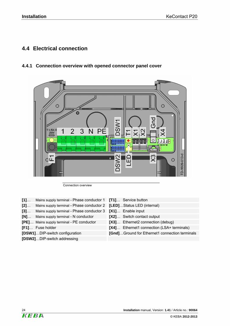
Connection overview
[1]… Mains supply terminal - Phase conductor 1 [T1]… Service button
[2]… Mains supply terminal - Phase conductor 2 [LED]…Status LED (internal)
[3]… Mains supply terminal - Phase conductor 3 [X1]… Enable input
[N]… Mains supply terminal - N conductor [X2]… Switch contact output
[PE]… Mains supply terminal - PE conductor [X3]… Ethernet2 connection (debug)
[F1]… Fuse holder [X4]… Ethernet1 connection (LSA+ terminals)
[DSW1]…DIP-switch configuration [Gnd]…Ground for Ethernet1 connection terminals
[DSW2]…DIP-switch addressing
KeContact P20 Installation
Installation manual, Version: 1.41 / Article no.: 90064 25
© KEBA 2012-2013
4.4.2 Connecting the mains supply line
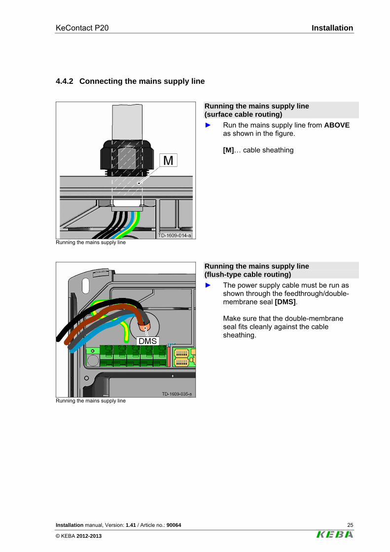
Running the mains supply line
Running the mains supply line (surface cable routing)
► Run the mains supply line from ABOVE as shown in the figure. [M]… cable sheathing
Running the mains supply line
Running the mains supply line (flush-type cable routing)
► The power supply cable must be run as shown through the feedthrough/double-membrane seal [DMS]. Make sure that the double-membrane seal fits cleanly against the cable sheathing.
Installation KeContact P20
26 Installation manual, Version: 1.41 / Article no.: 90064
© KEBA 2012-2013
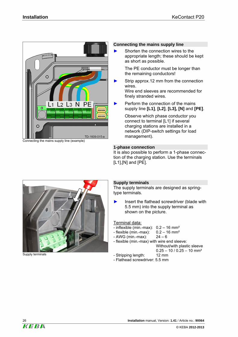
Connecting the mains supply line (example)
Connecting the mains supply line
► Shorten the connection wires to the appropriate length; these should be kept as short as possible.
The PE conductor must be longer than the remaining conductors!
► Strip approx.12 mm from the connection wires. Wire end sleeves are recommended for finely stranded wires.
► Perform the connection of the mains supply line [L1], [L2], [L3], [N] and [PE].
Observe which phase conductor you connect to terminal [L1] if several charging stations are installed in a network (DIP-switch settings for load management).
1-phase connection It is also possible to perform a 1-phase connec-tion of the charging station. Use the terminals [L1],[N] and [PE].
Supply terminals
Supply terminals The supply terminals are designed as spring-type terminals.
► Insert the flathead screwdriver (blade with 5.5 mm) into the supply terminal as shown on the picture.
Terminal data: - inflexible (min.-max): 0.2 – 16 mm² - flexible (min.-max): 0.2 – 16 mm² - AWG (min.-max): 24 – 6 - flexible (min.-max) with wire end sleeve: Without/with plastic sleeve 0.25 – 10 / 0.25 – 10 mm² - Stripping length: 12 mm - Flathead screwdriver: 5.5 mm
KeContact P20 Installation
Installation manual, Version: 1.41 / Article no.: 90064 27
© KEBA 2012-2013
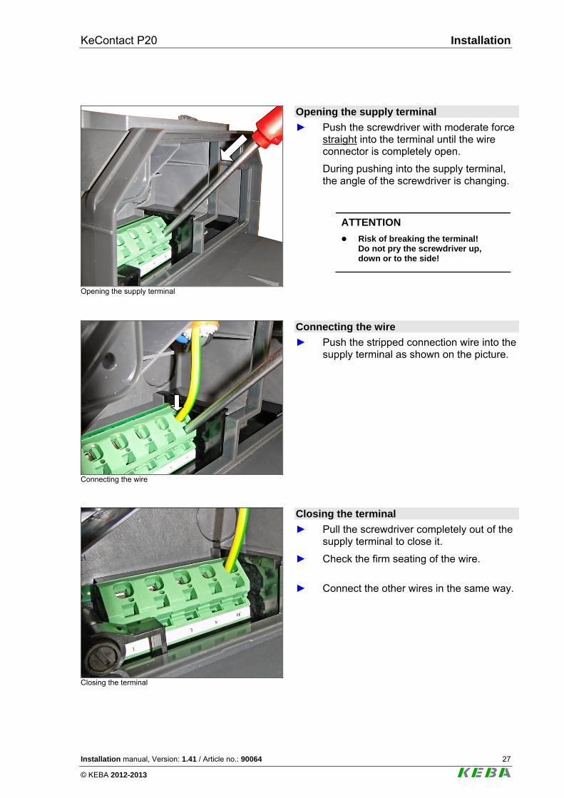
Opening the supply terminal
Opening the supply terminal
► Push the screwdriver with moderate force straight into the terminal until the wire connector is completely open.
During pushing into the supply terminal, the angle of the screwdriver is changing.
ATTENTION
Risk of breaking the terminal! Do not pry the screwdriver up, down or to the side!
Connecting the wire
Connecting the wire
► Push the stripped connection wire into the supply terminal as shown on the picture.
Closing the terminal
Closing the terminal
► Pull the screwdriver completely out of the supply terminal to close it.
► Check the firm seating of the wire.
► Connect the other wires in the same way.
Installation KeContact P20
28 Installation manual, Version: 1.41 / Article no.: 90064
© KEBA 2012-2013
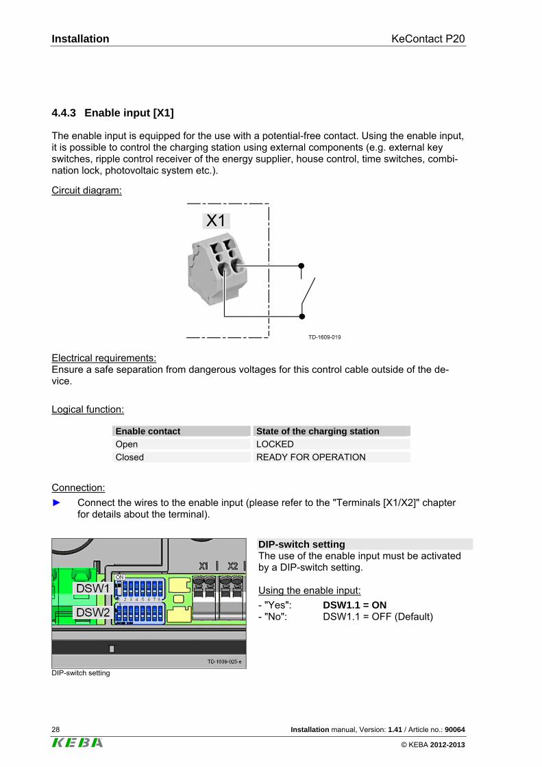
4.4.3 Enable input [X1]
The enable input is equipped for the use with a potential-free contact. Using the enable input, it is possible to control the charging station using external components (e.g. external key switches, ripple control receiver of the energy supplier, house control, time switches, combi-nation lock, photovoltaic system etc.).
Circuit diagram:
Electrical requirements: Ensure a safe separation from dangerous voltages for this control cable outside of the de-vice.
Logical function:
Enable contact State of the charging station
Open LOCKED
Closed READY FOR OPERATION
Connection:
► Connect the wires to the enable input (please refer to the "Terminals [X1/X2]" chapter for details about the terminal).
DIP-switch setting
DIP-switch setting The use of the enable input must be activated by a DIP-switch setting. Using the enable input:
- "Yes": DSW1.1 = ON - "No": DSW1.1 = OFF (Default)
KeContact P20 Installation
Installation manual, Version: 1.41 / Article no.: 90064 29
© KEBA 2012-2013
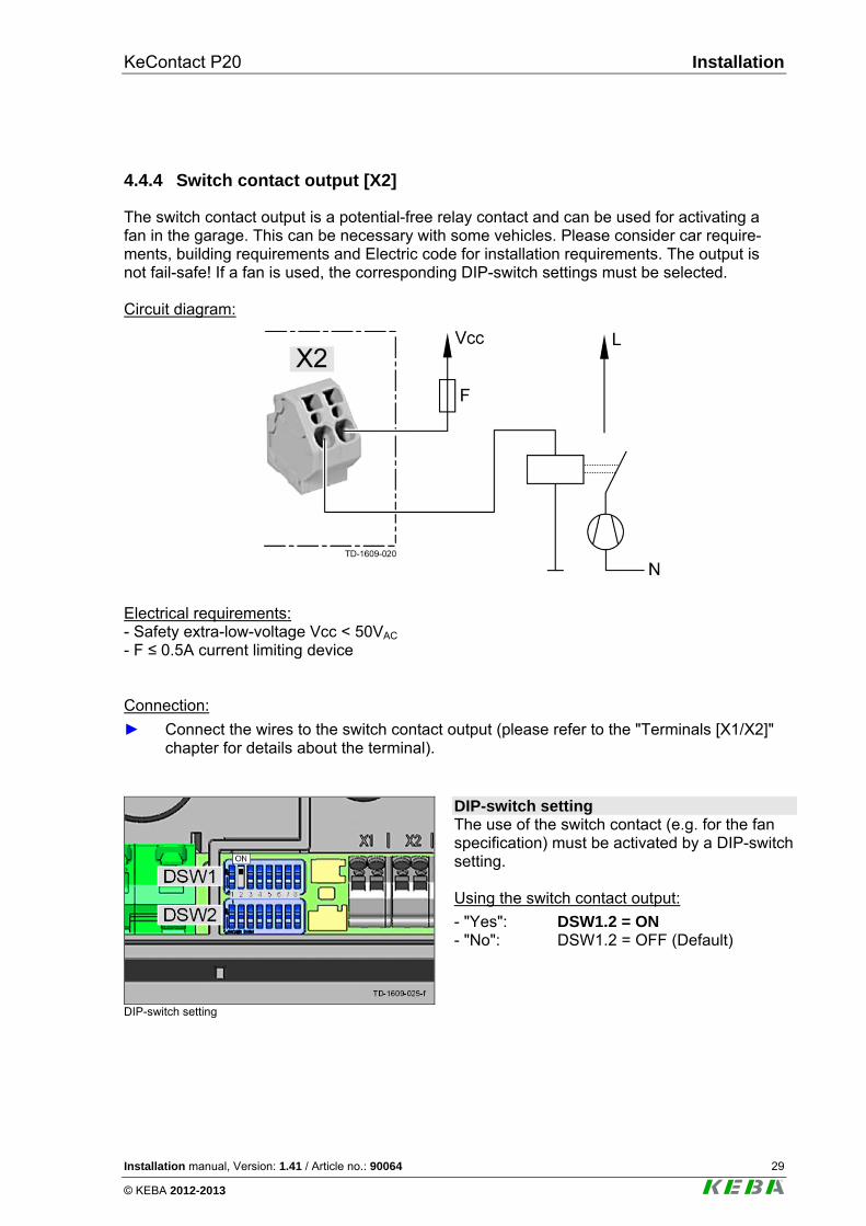
4.4.4 Switch contact output [X2]
The switch contact output is a potential-free relay contact and can be used for activating a fan in the garage. This can be necessary with some vehicles. Please consider car require-ments, building requirements and Electric code for installation requirements. The output is not fail-safe! If a fan is used, the corresponding DIP-switch settings must be selected. Circuit diagram:
Electrical requirements: - Safety extra-low-voltage Vcc < 50VAC - F ≤ 0.5A current limiting device
Connection:
► Connect the wires to the switch contact output (please refer to the "Terminals [X1/X2]" chapter for details about the terminal).
DIP-switch setting
DIP-switch setting The use of the switch contact (e.g. for the fan specification) must be activated by a DIP-switch setting. Using the switch contact output:
- "Yes": DSW1.2 = ON - "No": DSW1.2 = OFF (Default)
Installation KeContact P20
30 Installation manual, Version: 1.41 / Article no.: 90064
© KEBA 2012-2013
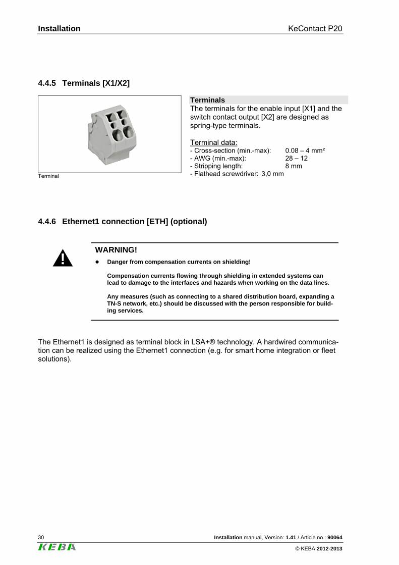
4.4.5 Terminals [X1/X2]
Terminal
Terminals The terminals for the enable input [X1] and the switch contact output [X2] are designed as spring-type terminals. Terminal data: - Cross-section (min.-max): 0.08 – 4 mm² - AWG (min.-max): 28 – 12 - Stripping length: 8 mm - Flathead screwdriver: 3,0 mm
4.4.6 Ethernet1 connection [ETH] (optional)
!
WARNING!
Danger from compensation currents on shielding! Compensation currents flowing through shielding in extended systems can lead to damage to the interfaces and hazards when working on the data lines. Any measures (such as connecting to a shared distribution board, expanding a TN-S network, etc.) should be discussed with the person responsible for build-ing services.
The Ethernet1 is designed as terminal block in LSA+® technology. A hardwired communica-tion can be realized using the Ethernet1 connection (e.g. for smart home integration or fleet solutions).
KeContact P20 Installation
Installation manual, Version: 1.41 / Article no.: 90064 31
© KEBA 2012-2013
Color coding:
According to the used wiring standard in the building, the contacts are wired according to TIA-568A/B for 100BaseT:
Pin -568A Pair
-568B Pair
-568A Color
-568B Color
1 (Tx+) 3 2 white/green stripe white/orange stripe
2 (Tx−) 3 2 green/white stripe or green
orange/white stripe or orange
3 (Rx+) 2 3 white/orange stripe white/green stripe
4 (Rx−) 2 3 orange/white stripe or orange
green/white stripe or green
Terminal data:
Category Wire diameter Insulation diameter
0.36 mm (AWG 27)
0.7 – 0.75 mm Inflexible cable Cat 5e / Cat6 STP
0.4 – 0,64 mm (AWG 26 – AWG 22)
0.7 – 1,4 mm
Cat 6 STP 0.51 – 0,81 mm (AWG 24 – AWG 20)
1.0 – 1,4 mm
Flexible cable Cat 5e / Cat 6 STP
7 x 0.2 mm (AWG 24)
1.1 – 1,4 mm
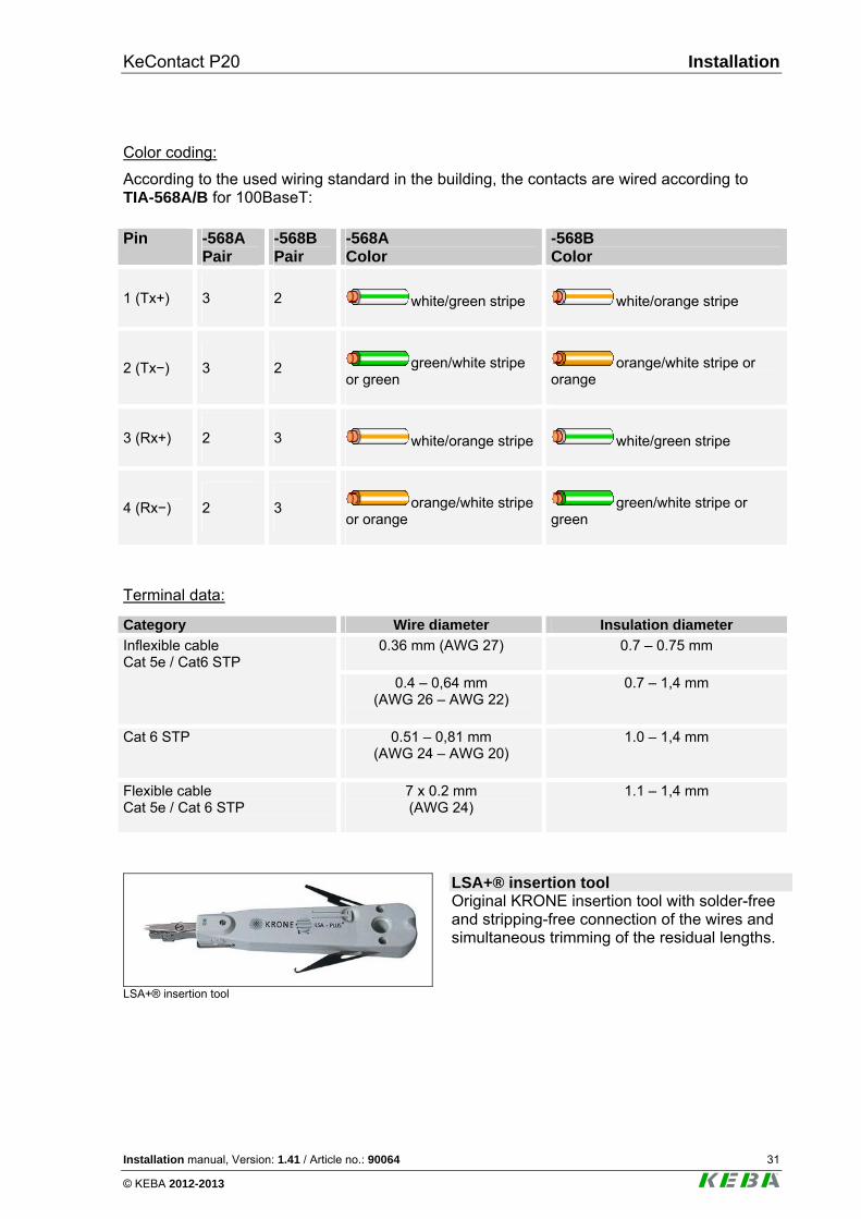
LSA+® insertion tool
LSA+® insertion tool Original KRONE insertion tool with solder-free and stripping-free connection of the wires and simultaneous trimming of the residual lengths.
Installation KeContact P20
32 Installation manual, Version: 1.41 / Article no.: 90064
© KEBA 2012-2013
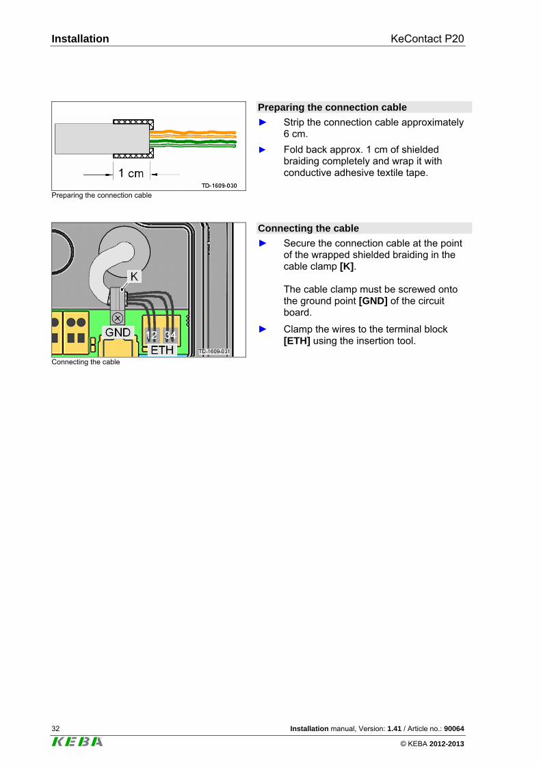
Preparing the connection cable
Preparing the connection cable
► Strip the connection cable approximately 6 cm.
► Fold back approx. 1 cm of shielded braiding completely and wrap it with conductive adhesive textile tape.
Connecting the cable
Connecting the cable
► Secure the connection cable at the point of the wrapped shielded braiding in the cable clamp [K]. The cable clamp must be screwed onto the ground point [GND] of the circuit board.
► Clamp the wires to the terminal block [ETH] using the insertion tool.
KeContact P20 Installation
Installation manual, Version: 1.41 / Article no.: 90064 33
© KEBA 2012-2013
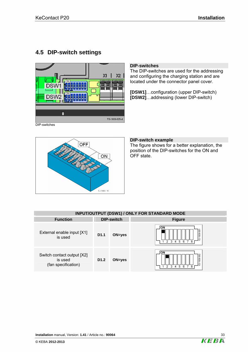
4.5 DIP-switch settings
DIP-switches
DIP-switches The DIP-switches are used for the addressing and configuring the charging station and are located under the connector panel cover. [DSW1]…configuration (upper DIP-switch) [DSW2]…addressing (lower DIP-switch)
DIP-switch example The figure shows for a better explanation, the position of the DIP-switches for the ON and OFF state.
INPUT/OUTPUT (DSW1) / ONLY FOR STANDARD MODE
Function DIP-switch Figure
External enable input [X1] is used
D1.1 ON=yes
Switch contact output [X2] is used
(fan specification) D1.2 ON=yes
Installation KeContact P20
34 Installation manual, Version: 1.41 / Article no.: 90064
© KEBA 2012-2013
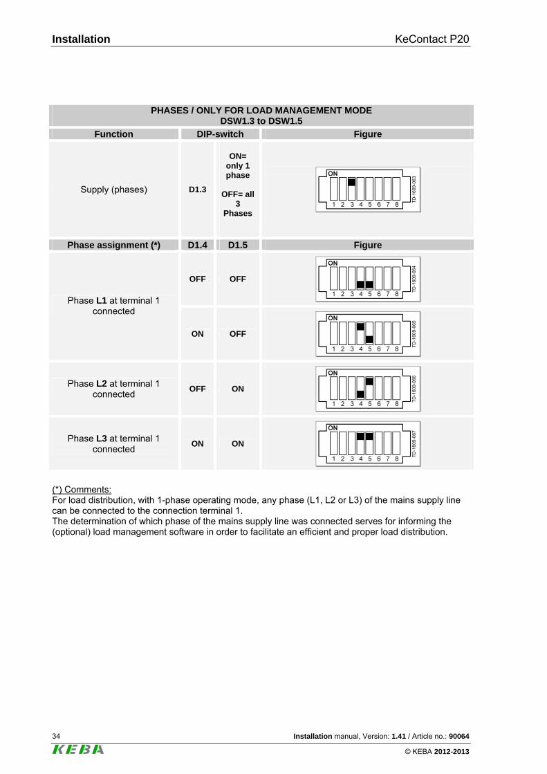
PHASES / ONLY FOR LOAD MANAGEMENT MODE
DSW1.3 to DSW1.5
Function DIP-switch Figure
Supply (phases) D1.3
ON=
only 1 phase
OFF= all
3 Phases
Phase assignment (*) D1.4 D1.5 Figure
OFF OFF
Phase L1 at terminal 1
connected
ON OFF
Phase L2 at terminal 1 connected
OFF ON
Phase L3 at terminal 1 connected
ON ON
(*) Comments: For load distribution, with 1-phase operating mode, any phase (L1, L2 or L3) of the mains supply line can be connected to the connection terminal 1. The determination of which phase of the mains supply line was connected serves for informing the (optional) load management software in order to facilitate an efficient and proper load distribution.
KeContact P20 Installation
Installation manual, Version: 1.41 / Article no.: 90064 35
© KEBA 2012-2013
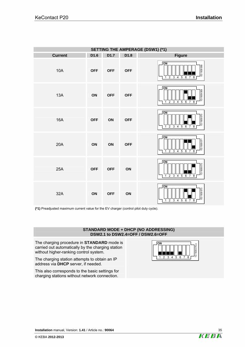
SETTING THE AMPERAGE (DSW1) (*1)
Current D1.6 D1.7 D1.8 Figure
10A OFF OFF OFF
13A ON OFF OFF
16A OFF ON OFF
20A ON ON OFF
25A OFF OFF ON
32A ON OFF ON
(*1) Preadjusted maximum current value for the EV charger (control pilot duty cycle).
STANDARD MODE + DHCP (NO ADDRESSING) DSW2.1 to DSW2.4=OFF / DSW2.6=OFF
The charging procedure in STANDARD mode is carried out automatically by the charging station without higher-ranking control system.
The charging station attempts to obtain an IP address via DHCP server, if needed.
This also corresponds to the basic settings for charging stations without network connection.
Installation KeContact P20
36 Installation manual, Version: 1.41 / Article no.: 90064
© KEBA 2012-2013
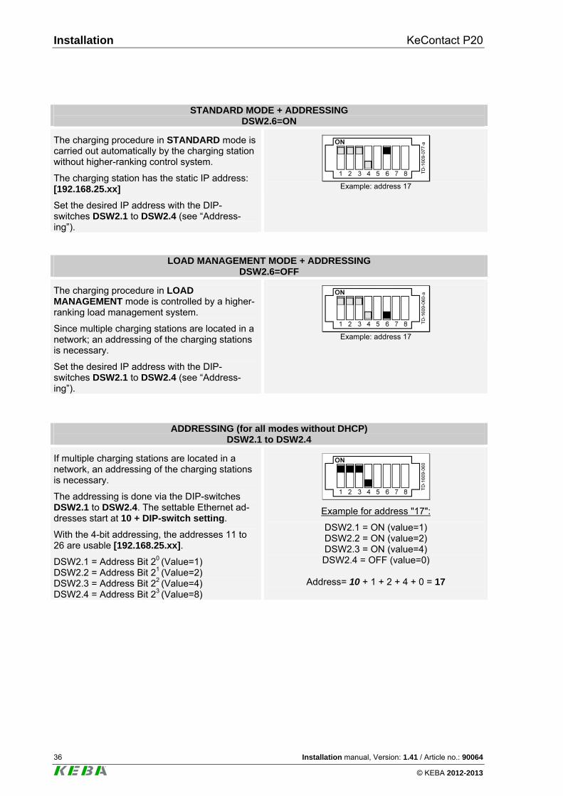
STANDARD MODE + ADDRESSING DSW2.6=ON
The charging procedure in STANDARD mode is carried out automatically by the charging station without higher-ranking control system.
The charging station has the static IP address: [192.168.25.xx]
Set the desired IP address with the DIP-switches DSW2.1 to DSW2.4 (see “Address-ing”).
Example: address 17
LOAD MANAGEMENT MODE + ADDRESSING DSW2.6=OFF
The charging procedure in LOAD MANAGEMENT mode is controlled by a higher-ranking load management system.
Since multiple charging stations are located in a network; an addressing of the charging stations is necessary.
Set the desired IP address with the DIP-switches DSW2.1 to DSW2.4 (see “Address-ing”).
Example: address 17
ADDRESSING (for all modes without DHCP) DSW2.1 to DSW2.4
If multiple charging stations are located in a network, an addressing of the charging stations is necessary.
The addressing is done via the DIP-switches DSW2.1 to DSW2.4. The settable Ethernet ad-dresses start at 10 + DIP-switch setting.
With the 4-bit addressing, the addresses 11 to 26 are usable [192.168.25.xx].
DSW2.1 = Address Bit 20 (Value=1) DSW2.2 = Address Bit 21 (Value=2) DSW2.3 = Address Bit 22 (Value=4) DSW2.4 = Address Bit 23 (Value=8)
Example for address "17":
DSW2.1 = ON (value=1) DSW2.2 = ON (value=2) DSW2.3 = ON (value=4) DSW2.4 = OFF (value=0)
Address= 10 + 1 + 2 + 4 + 0 = 17
KeContact P20 Installation
Installation manual, Version: 1.41 / Article no.: 90064 37
© KEBA 2012-2013
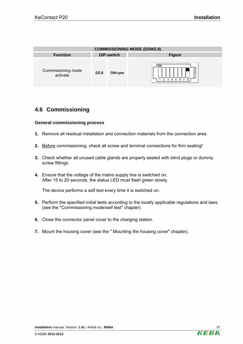
COMMISSIONING MODE (DSW2.8)
Function DIP-switch Figure
Commissioning mode activate
D2.8 ON=yes
4.6 Commissioning
General commissioning process 1. Remove all residual installation and connection materials from the connection area.
2. Before commissioning, check all screw and terminal connections for firm seating!
3. Check whether all unused cable glands are properly sealed with blind plugs or dummy screw fittings.
4. Ensure that the voltage of the mains supply line is switched on. After 15 to 20 seconds, the status LED must flash green slowly. The device performs a self test every time it is switched on.
5. Perform the specified initial tests according to the locally applicable regulations and laws (see the "Commissioning mode/self test" chapter).
6. Close the connector panel cover to the charging station.
7. Mount the housing cover (see the " Mounting the housing cover" chapter).
Installation KeContact P20
38 Installation manual, Version: 1.41 / Article no.: 90064
© KEBA 2012-2013
4.6.1 Commissioning mode/self test
General The charging station can be placed into a commissioning mode for supporting the initial sys-tem test. During this, a self test of the device is performed (interlocking, contactor activation, current measurement, etc.) and the result is displayed. After successful test without connected vehicle, the contactor is switched for limited time in order to facilitate the initial tests. A normal charging procedure is not possible in commission-ing mode. The interlocking of the connector socket is activated to prevent a cable from being plugged in. Activating the commissioning mode
► Set the IBN DIP-switch DSW2.8 to ON (see "DIP-switch settings").
► Perform a reset of the charging station. To do this press the [Service button] for 1 second or switch the power supply voltage off/on. The commissioning mode is now activated and is indicated by the orange status LED (lights continuously).
► You now have the option for approximately 5 min. to contact with standard test probes using the measuring device ( e.g. Astaco® test probes from BEHA) and to perform the necessary tests (see chapter "Safety checks"). After 5 min. have elapsed, the contactor is deactivated in the charging station is shut down.
Deactivating commissioning mode
► Set the IBN DIP-switch DSW2.8 to OFF again.
► Perform a reset of the charging station. To do this, press the [Service button] for 1 second or switch the power supply voltage off/on. The charging station starts up again in normal mode and is ready for operation.
KeContact P20 Installation
Installation manual, Version: 1.41 / Article no.: 90064 39
© KEBA 2012-2013
4.6.2 Safety checks
Before the initial use, check the effectiveness of the safety measure(s) of the system accord-ing to the nationally applicable regulations (e.g.:ÖVE/ÖNORM E8001-6-61, DIN VDE 0100-600:2008-06 "Checks,...")!
Electrical systems or devices must be checked by the installer of the system or device before their initial operation. This also applies for the expansion or modification of existing systems or electrical devices.
However, it is essential that all conditions for the safety measures are observed. Moreover, the following points are to be taken into account:
► The checks (continuity of the connections of the protective conductor, insulation resistance, RCD (FI) triggering current, triggering time,…) are to be performed for the expanded or modified part.
► The measurement devices must comply with the national regulations! (e.g.: DIN EN 60557 (VDE 0413) "Electrical safety in low-voltage distribution systems up to AC 1000V and DC 1500V").
► The measurement results are to be documented. A test report is to be created and saved before the check.
Installation KeContact P20
40 Installation manual, Version: 1.41 / Article no.: 90064
© KEBA 2012-2013
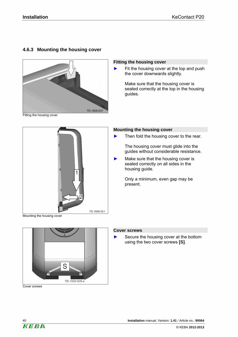
4.6.3 Mounting the housing cover
Fitting the housing cover
Fitting the housing cover
► Fit the housing cover at the top and push the cover downwards slightly. Make sure that the housing cover is seated correctly at the top in the housing guides.
Mounting the housing cover
Mounting the housing cover
► Then fold the housing cover to the rear. The housing cover must glide into the guides without considerable resistance.
► Make sure that the housing cover is seated correctly on all sides in the housing guide. Only a minimum, even gap may be present.
Cover screws
Cover screws
► Secure the housing cover at the bottom using the two cover screws [S].
KeContact P20 Further technical instructions
Installation manual, Version: 1.41 / Article no.: 90064 41
© KEBA 2012-2013
5 Further technical instructions
5.1 Programming RFID cards (optional)
Programming the RFID master card
The authorization by an RFID master card is necessary for the programming. The programming mode can be activated and deactivated using the RFID master card.
The first RFID card that is detected by the charging station will automatically be stored as the master card.
► Hold the RFID master card to be programmed in front of the RFID sensor and wait for the signal tone. The RFID master card is now programmed. Keep this card in a safe place.
Programming RFID user cards
► Hold the RFID master card in front of the RFID sensor and wait for the signal tone.
► Hold the new RFID user card in front of the RFID sensor within 5 seconds and wait for the signal tone.
► To confirm, hold the RFID master card in front of the RFID sensor again within 5 seconds and wait for the signal tone. The RFID user card is now programmed.
Deleting all RFID cards from memory
► Remove the housing cover and open the connector panel cover of the charging station.
► Press the [Service button] for 5 seconds. All saved RFID cards (including the RFID master card) are now deleted.
► Now start again with the programming of the RFID master card.
Further technical instructions KeContact P20
42 Installation manual, Version: 1.41 / Article no.: 90064
© KEBA 2012-2013
5.2 Configure the communication with the EV PLC->Ethernet (optional)
To allow the access of the vehicle to the home network or internet, the power line communi-cation between vehicle and charging station must be configured on both sides with the same password (NMK „Network Membership Key“). The default password is „emobility“. It is recommended to change this password. The required software ("EV Communication Assistant“) including the instructions how to con-figure the charging station, you can find in the download area under www.kecontact.com. Further details how to configure your vehicle, please see the manufacturer’s manual of your vehicle.
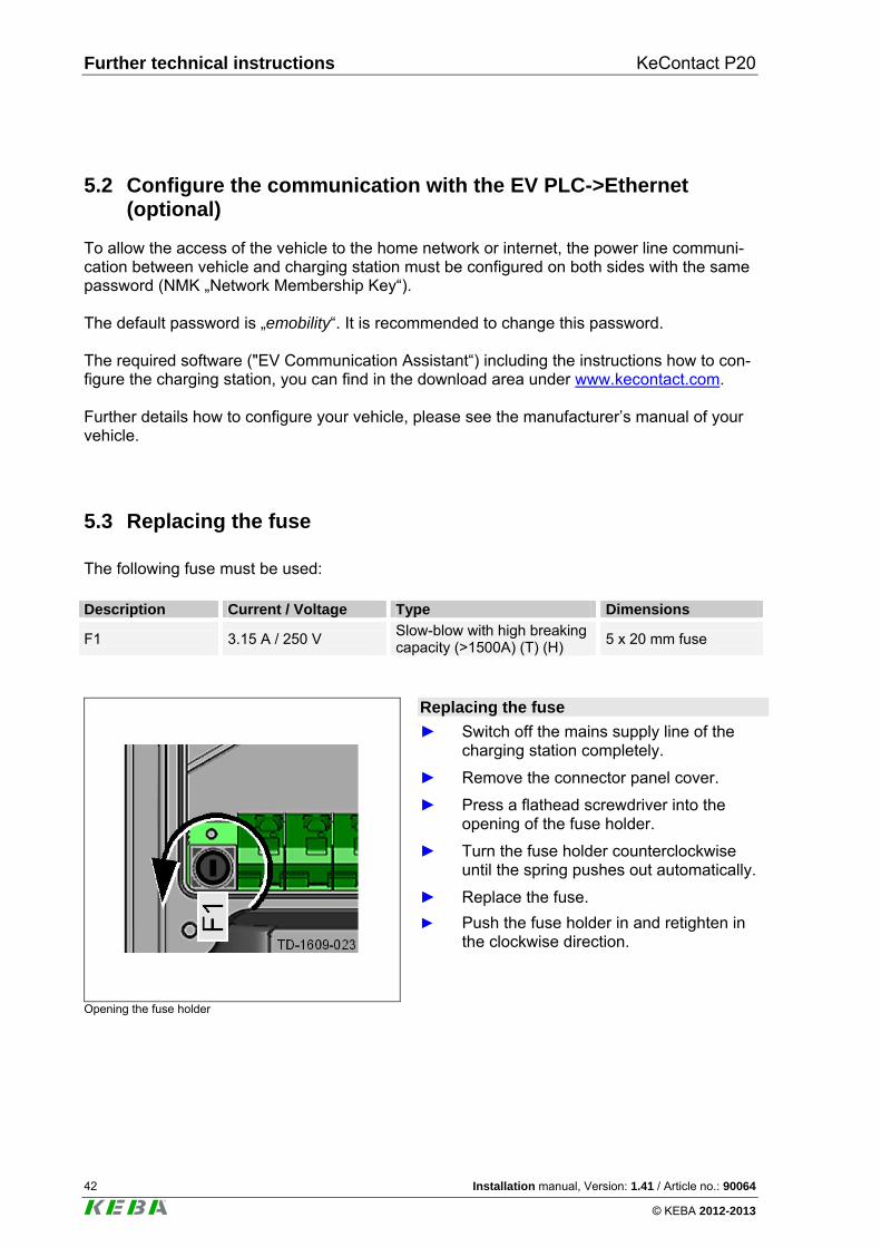
5.3 Replacing the fuse
The following fuse must be used: Description Current / Voltage Type Dimensions
F1 3.15 A / 250 V Slow-blow with high breaking capacity (>1500A) (T) (H)
5 x 20 mm fuse
Opening the fuse holder
Replacing the fuse
► Switch off the mains supply line of the charging station completely.
► Remove the connector panel cover.
► Press a flathead screwdriver into the opening of the fuse holder.
► Turn the fuse holder counterclockwise until the spring pushes out automatically.
► Replace the fuse.
► Push the fuse holder in and retighten in the clockwise direction.
KeContact P20 Further technical instructions
Installation manual, Version: 1.41 / Article no.: 90064 43
© KEBA 2012-2013
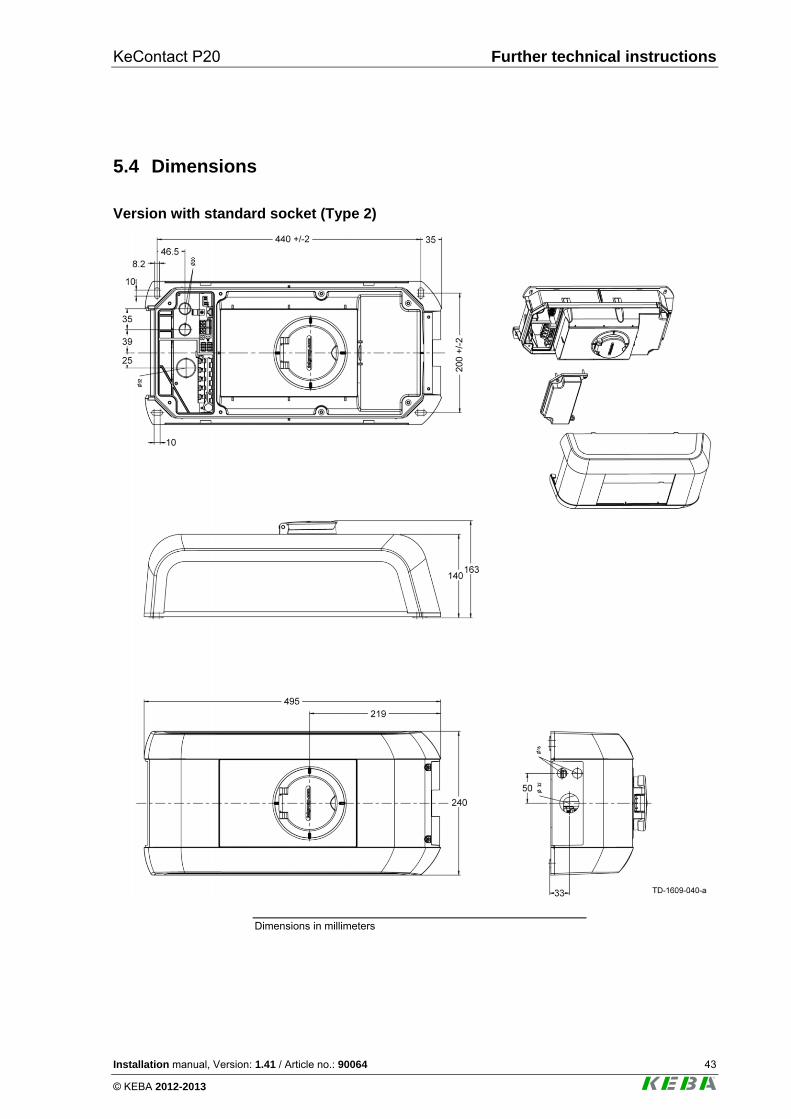
5.4 Dimensions
Version with standard socket (Type 2)
Dimensions in millimeters
Further technical instructions KeContact P20
44 Installation manual, Version: 1.41 / Article no.: 90064
© KEBA 2012-2013
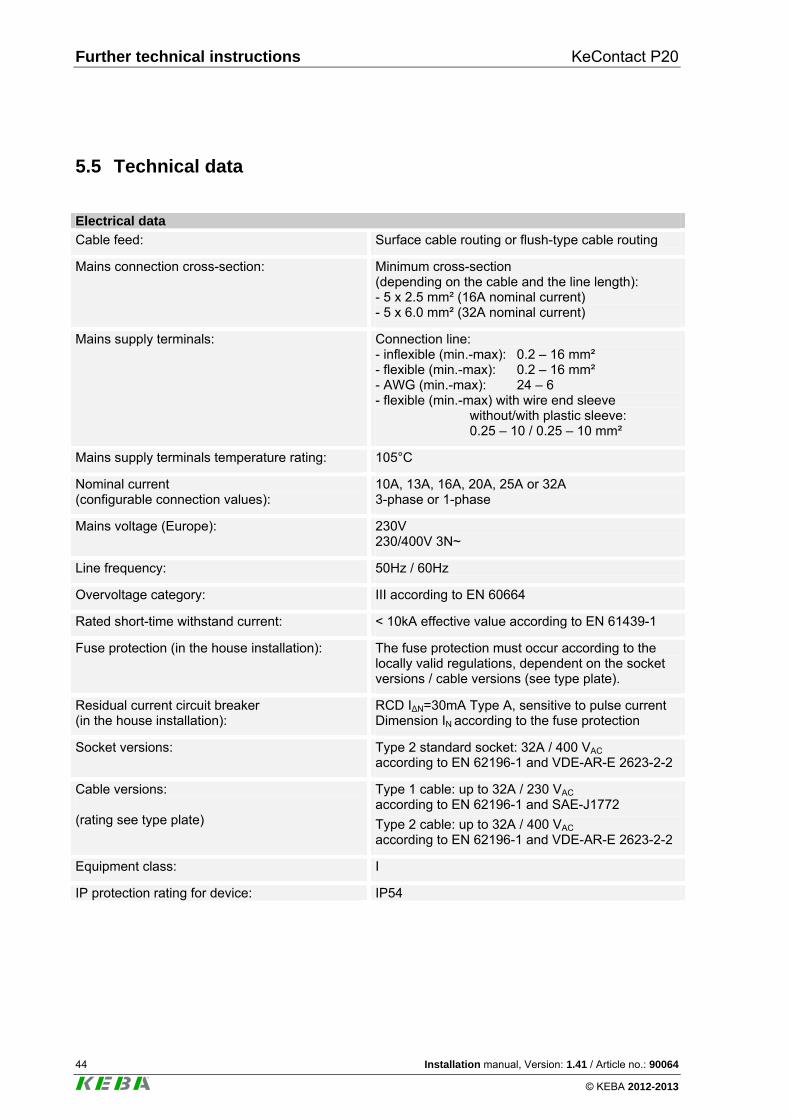
5.5 Technical data
Electrical data
Cable feed: Surface cable routing or flush-type cable routing
Mains connection cross-section: Minimum cross-section (depending on the cable and the line length): - 5 x 2.5 mm² (16A nominal current) - 5 x 6.0 mm² (32A nominal current)
Mains supply terminals: Connection line: - inflexible (min.-max): 0.2 – 16 mm² - flexible (min.-max): 0.2 – 16 mm² - AWG (min.-max): 24 – 6 - flexible (min.-max) with wire end sleeve without/with plastic sleeve: 0.25 – 10 / 0.25 – 10 mm²
Mains supply terminals temperature rating:
105°C
Nominal current (configurable connection values):
10A, 13A, 16A, 20A, 25A or 32A 3-phase or 1-phase
Mains voltage (Europe): 230V 230/400V 3N~
Line frequency: 50Hz / 60Hz
Overvoltage category: III according to EN 60664
Rated short-time withstand current: < 10kA effective value according to EN 61439-1
Fuse protection (in the house installation): The fuse protection must occur according to the locally valid regulations, dependent on the socket versions / cable versions (see type plate).
Residual current circuit breaker (in the house installation):
RCD I∆N=30mA Type A, sensitive to pulse current Dimension IN according to the fuse protection
Socket versions: Type 2 standard socket: 32A / 400 VAC according to EN 62196-1 and VDE-AR-E 2623-2-2
Cable versions: (rating see type plate)
Type 1 cable: up to 32A / 230 VAC according to EN 62196-1 and SAE-J1772
Type 2 cable: up to 32A / 400 VAC according to EN 62196-1 and VDE-AR-E 2623-2-2
Equipment class: I
IP protection rating for device: IP54
KeContact P20 Further technical instructions
Installation manual, Version: 1.41 / Article no.: 90064 45
© KEBA 2012-2013
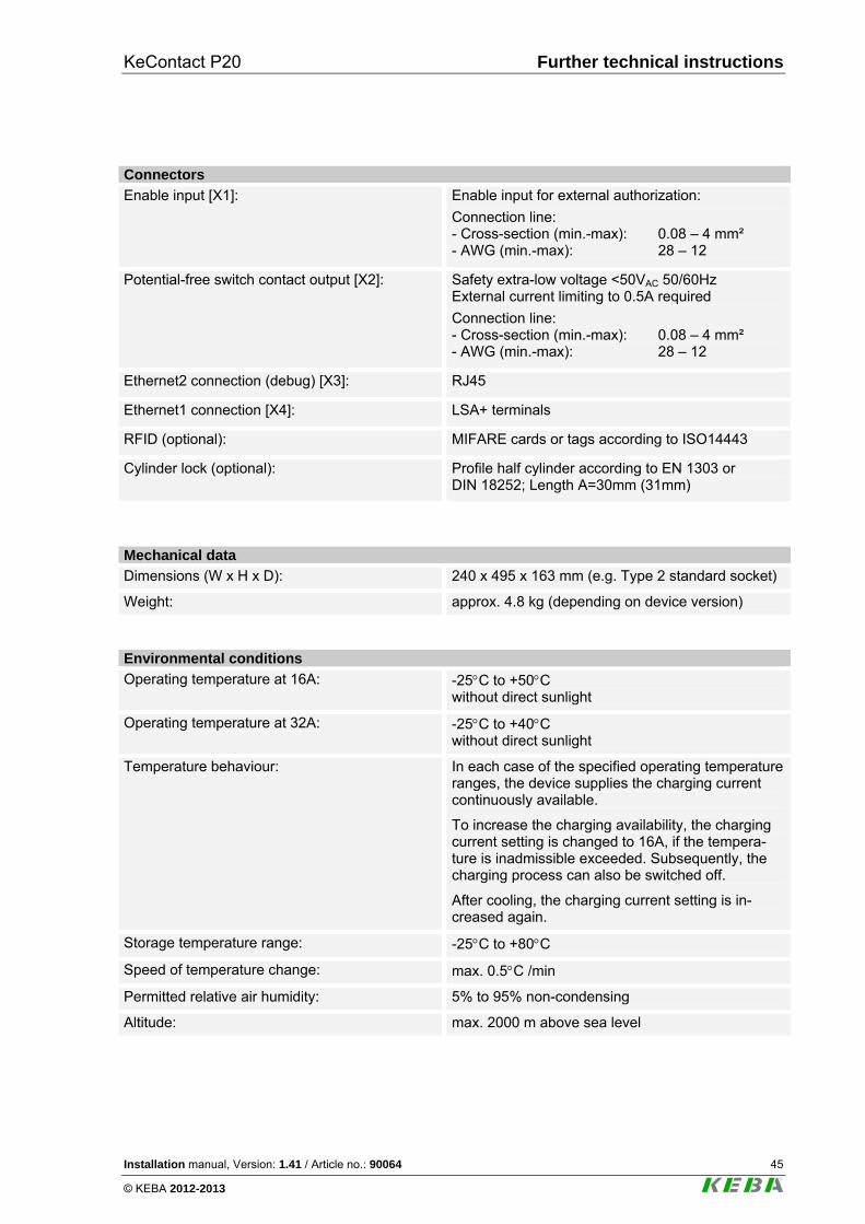
Connectors
Enable input [X1]: Enable input for external authorization:
Connection line: - Cross-section (min.-max): 0.08 – 4 mm² - AWG (min.-max): 28 – 12
Potential-free switch contact output [X2]: Safety extra-low voltage <50VAC 50/60Hz External current limiting to 0.5A required
Connection line: - Cross-section (min.-max): 0.08 – 4 mm² - AWG (min.-max): 28 – 12
Ethernet2 connection (debug) [X3]: RJ45
Ethernet1 connection [X4]: LSA+ terminals
RFID (optional): MIFARE cards or tags according to ISO14443
Cylinder lock (optional): Profile half cylinder according to EN 1303 or DIN 18252; Length A=30mm (31mm)
Mechanical data
Dimensions (W x H x D): 240 x 495 x 163 mm (e.g. Type 2 standard socket)
Weight: approx. 4.8 kg (depending on device version)
Environmental conditions
Operating temperature at 16A: -25C to +50C without direct sunlight
Operating temperature at 32A:
-25C to +40C without direct sunlight
Temperature behaviour:
In each case of the specified operating temperature ranges, the device supplies the charging current continuously available.
To increase the charging availability, the charging current setting is changed to 16A, if the tempera-ture is inadmissible exceeded. Subsequently, the charging process can also be switched off.
After cooling, the charging current setting is in-creased again.
Storage temperature range: -25C to +80C
Speed of temperature change: max. 0.5C /min
Permitted relative air humidity: 5% to 95% non-condensing
Altitude: max. 2000 m above sea level
Further technical instructions KeContact P20
46 Installation manual, Version: 1.41 / Article no.: 90064
© KEBA 2012-2013
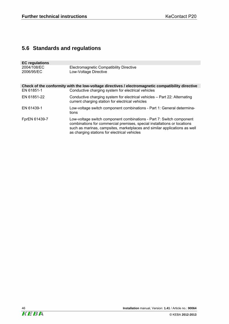
5.6 Standards and regulations
EC regulations 2004/108/EC Electromagnetic Compatibility Directive 2006/95/EC Low-Voltage Directive Check of the conformity with the low-voltage directives / electromagnetic compatibility directive EN 61851-1 Conductive charging system for electrical vehicles
EN 61851-22
Conductive charging system for electrical vehicles – Part 22: Alternating current charging station for electrical vehicles
EN 61439-1 Low-voltage switch component combinations - Part 1: General determina-tions
FprEN 61439-7 Low-voltage switch component combinations - Part 7: Switch component combinations for commercial premises, special installations or locations such as marinas, campsites, marketplaces and similar applications as well as charging stations for electrical vehicles
KeContact P20 INDEX
Installation manual, Version: 1.41 / Article no.: 90064 47
© KEBA 2012-2013
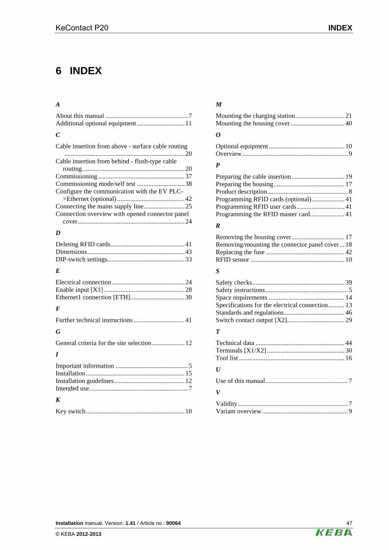
6 INDEX
A
About this manual ..................................................7 Additional optional equipment .............................11
C
Cable insertion from above - surface cable routing.........................................................................20
Cable insertion from behind - flush-type cable routing..............................................................20
Commissioning.....................................................37 Commissioning mode/self test .............................38 Configure the communication with the EV PLC-
>Ethernet (optional) .........................................42 Connecting the mains supply line.........................25 Connection overview with opened connector panel
cover.................................................................24
D
Deleting RFID cards.............................................41 Dimensions...........................................................43 DIP-switch settings...............................................33
E
Electrical connection ............................................24 Enable input [X1] .................................................28 Ethernet1 connection [ETH].................................30
F
Further technical instructions ...............................41
G
General criteria for the site selection....................12
I
Important information ............................................5 Installation............................................................15 Installation guidelines...........................................12 Intended use............................................................7
K
Key switch............................................................10
M
Mounting the charging station.............................. 21 Mounting the housing cover................................. 40
O
Optional equipment .............................................. 10 Overview................................................................ 9
P
Preparing the cable insertion ................................ 19 Preparing the housing........................................... 17 Product description................................................. 8 Programming RFID cards (optional).................... 41 Programming RFID user cards............................. 41 Programming the RFID master card..................... 41
R
Removing the housing cover................................ 17 Removing/mounting the connector panel cover... 18 Replacing the fuse ................................................ 42 RFID sensor ......................................................... 10
S
Safety checks........................................................ 39 Safety instructions .................................................. 5 Space requirements .............................................. 14 Specifications for the electrical connection.......... 13 Standards and regulations..................................... 46 Switch contact output [X2]................................... 29
T
Technical data ...................................................... 44 Terminals [X1/X2] ............................................... 30 Tool list ................................................................ 16
U
Use of this manual.................................................. 7
V
Validity................................................................... 7 Variant overview.................................................... 9