Embed Size (px)
Citation preview

KE2 WiFi Service Tool(pn 20906)
KE2 LDA (pn 21253)
Application:▪ Designed for small to mid-sized racks - eliminates overly
complicated controls that are designed for larger systems.
▪ Easily applied to new or existing installations.
▪ Supports up to 5 stages of loading with onboard relays.
▪ On racks with compressors all of equal HP, will automatically equalize runtime
▪ Racks with compressors of varying HP, it maintains consis-tent suction pressure.
▪ Master View webpages, allows technicians to quickly and easily assess the system’s operation & Review historical per-formance using onboard data logging.
▪ Works as a stand-alone rack controller or in conjunction with KE2 Evaporator Efficiency controllers.
▪ Can limit the amount of defrost load, as dictated by the site’s electrical requirements.
The KE2 Compressor Sequencer is new to KE2 Therm’s refrigeration con-trols suite. Designed for small to mid-sized racks, The KE2 Compressor Sequencer brings the controller’s features in line with the job’s require-ments. It eliminates the necessity of using overly complicated controls designed for larger systems.
The KE2 Compressor Sequencer replaces aging rack controllers or can retrofit racks with existing mechanical controls.
The controller supports up to 5 stages of loading through its onboard relays. Each relay can be configured as the rack’s: Fixed Speed Compres-sor, Compressor Unloader, Digital Scroll Compressor, Master Liquid Line Solenoid, or Hot Gas Defrost Relay.
When applied to racks with compressors all of equal horse power, the controller will automatically equalize the runtime of each compressor. Compressors can also be of various HP. When more than one HP is se-lected the controller will use the stage with the smallest capacity, to maintain consistent suction pressure.
The KE2 Compressor Sequencer includes KE2 Therm’s Master View web-pages, allowing technicians to quickly and easily assess the system’s operation, and review historical performance through onboard data logging.
The compressor sequencer works as a stand-alone rack controller or in conjunction with KE2 Evaporator Efficiency controllers. When applied with the KE2 Evaporator Efficiency controllers the KE2 Compressor Se-quencer can limit the amount of defrost load, as dictated by the site’s electrical requirements.
Part Numbers - Controllers & AccessoriesPart Number Description
KE2 Compressor Sequencer21246 Controller only
Pressure Transducers20201 Pressure Transducer – 0 to 150 psia, 10 ft. leads20202 Pressure Transducer – 0 to 500 psig, 10 ft. leads
Temperature Sensors21230 High temp for discharge at condenser inlet, 15 ft.20199 Standard for all other temp inputs, 10 ft. (black)
Solid State Relay
21304 Solid State Relay for Compressor Sequencer (used to control 5th compressor stage or digital scroll
© Copyright 2018 KE2 Therm Solutions, Inc., Washington, Missouri 63090
Q.2.43April 2018
KE2 Compressor Sequencer pn 21710
Quick Start GuideThis reference should remain on site with the installed KE2 Compressor Sequencer
Parts List - Included The following are included in the KE2 Compressor Sequencer kit 21710:
(1) KE2 Compressor Sequencer 120/208-240 VAC controller(1) high voltage safety shield(1) 15’ high-temperature sensor (1) 0-150 psia pressure transducer with 10ft. lead(1) 0-500 psig pressure transducer with 10ft. lead(1) 10 ft. temperature sensor for suction temperature (4) 90 degree quick disconnects (4) self-tapping screws(2) course thread screws (1) fine thread machine screw with lock washer(4) wire ties (rated for high & low temp)(1) 5-position pluggable connector (4) 3-position pluggable connectors (for power in, transducer & 3A relay)(9) 2-position pluggable connectors (for sensors & digital input, analog output)(1) 120 Voltage jumper(1) 208-240V Voltage jumper (already installed on controller)
Other Supplies - Not IncludedThe KE2 Compressor Sequencer installation requires standard truck stock items. A list of items is provided.
Conduit to go between the controller and the electrical panel (2) Conduit connectors (straight or elbow as required) High voltage wires matched to the number of compressors, liquid line so-
lenoid (if used), and the controller Wire labeling (numbers, colors, etc.) Additional wire ties 18 gauge twisted shielded pair (if extending sensor wires)
Before you begin:NOTE: After the controller is wired, the KE2 Compressor Sequencer is setup using the controller’s onboard webpage.
To access the webpage on the controller you will need a laptop and Ethernet cable, or a mobile device and either the KE2 LDA communica-tion device, or the KE2 WiFi Service Tool. (See page 3)

Q.2.43 April 2018Page 2
KE2 Compressor SequencerQuick Start Guide
© Copyright 2018 KE2 Therm Solutions, Inc., Washington, Missouri 63090
D1
D3
D2
Grou
nd
T2 A
ir O
ption
al
T3 D
ischa
rge
T1 Su
ctio
n
GREE
N (S
IGNA
L)
Digi
tal S
crol
l Unl
oade
r (0
-10V
ANA
LOG
OuT)
RED
(+5V
)BL
ACK
(GRO
UND)
PT SH
DIGITAL INPUTS
ROUTER / SWITCH
CAT5e CABLE(ETHERNET)
RJ 45
L1
NO NCCOM
NO NCCOM
COM
NONC
COM
NONC
LINE
NEUTRALGROUND
CONTROLLER POWER INPUT
KE2 COMPRESSOR SEQUENCER - Fixed Speed Compressors
COMP STAGE 4
COMP STAGE3
COMP STAGE 2
COMP STAGE 1
VOLTAGE JUMPER208-240V Default
L1
CON2
Compressor 2
CON1
Compressor 1
L1
L1
L1
– +
CON3Compressor 3
CON4Compressor 4
Sign
al
– +
PT DH
GREE
N
RED BLAC
K
+14V
EXTERNAL DIGITAL SWITCH
12 VDC; 100 OHMS 120 AMPS
CON5
Compressor 5
L2
LEGEND
Digital Scroll Unloader − Analog output to control digital scroll compressor.
PT SH − 0-150 psia pressure transducer for suction header
T1 Suction − -50° to 150°F Tempera-ture sensor for suction header
T2 Air − Optional -50° to 150°F tempera-ture sensor for space temperature. Allows �oating suction control feature.
T3 Discharge − 0° to 300°F temperature sensor for discharge header
PT DH − 0 to 500 psig pressure transducer for discharge header
Wiring the Controller
D1
D3
D2
Grou
nd
T2 A
ir O
ption
al
T3 D
ischa
rge
T1 Su
ctio
n
GREE
N (S
IGNA
L)
Digi
tal S
crol
l Unl
oade
r (0
-10V
ANA
LOG
Out)
RED
(+5V
)BL
ACK
(GRO
UND)
PT SH
DIGITAL INPUTS
ROUTER / SWITCH
CAT5e CABLE(ETHERNET)
RJ 45
L1
NO NCCOM
NO NCCOM
COM
NONC
COM
NONC
LINE
NEUTRALGROUND
CONTROLLER POWER INPUT
KE2 COMPRESSOR SEQUENCER - Compressor with Unloaders
COMP STAGE 4
COMP STAGE3
COMP STAGE 2
COMP STAGE 1
VOLTAGE JUMPER208-240V Default
L1
CON2
Unloader 1
CON1
Compressor 1
L1
L1
L1
– +
CON3Unloader 2
CON4Compressor 2
Sign
al
– +
PT DH
GREE
N
RED BLAC
K
+14V
EXTERNAL DIGITAL SWITCH
12 VDC; 100 OHMS 120 AMPS
CON5
Compressor 3
L2
NOTE : Unloaders are wired to the Normally Closed contacts

Q.2.43 April 2018Page 3
KE2 Compressor SequencerQuick Start Guide
© Copyright 2018 KE2 Therm Solutions, Inc., Washington, Missouri 63090
Setup the controller by going to the Setpoints page.
❶ After the controller is wired, the KE2 Compressor Sequencer is setup using the controller’s onboard webpage. To access the webpage on the controller you will need a laptop and Ethernet cable, or a mobile device and either the KE2 LDA com-munication device, or the KE2 WiFi Service Tool.
Power Up & Enter Setpoints
thermsolutions
ENTER
BACK
CompressorSequencer
®
Controller wired and ready
Ethernet Cable
Computer
thermsolutions
ENTER
BACK
CompressorSequencer
®
Superheat0.0 F
Suct Pressure96.2 F
Suct Temp87.7 F
Superheat0.0 F
Suct Pressure96.2 F
Suct Temp87.7 F
Controller wired and ready
Ethernet Cable
Computer, Tablet or Smart Phone
thermsolutionsPWR WIFILANWAN 3G/4G
Ethernet Cablethermsolutions
ENTER
BACK
CompressorSequencer
®
Controller wired and ready
Superheat0.0 F
Suct Pressure96.2 F
Suct Temp87.7 F
Computer, Tablet or Smart Phone
Option A
Option B
Option C
NOTE: Computer requires Static IP. See bulletin Q.5.11
❸ This will take you to the controller’s Home Page. From the Home Page select the Setpoints tab.
❷ Enter the controller’s IP address, into your web browser’s address bar. The IP ad-dress is found on a sticker on the controller.
SpecificationsControllerInput Voltage: 100VAC - 240VAC
Ambient Temp: -40°F to 140°F (-40°C to 60°C)
Operating Temp: -40°F to 140°F (-40°C to 60°C)
Inputs:(3) temperature sensor
(3) digital input
(2) pressure sensor inputs
Relays: (4)10A inductive fan contactor pilot
Digital Input
No function, Compressor Module, Oil Safety Switch, High Pressure Switch, System Off, 2nd Pressure Set Point
Communication: Standard TCP/IP
Pressure Transducer - pn 20201 (10 ft lead) Pressure Range: 0 to 150 psig
Proof Pressure: 450 psi
Burst Pressure: 1500psi
Operating Temp: -40°F to 275°F (-40°C to 135°C)
Pressure Transducer - pn 20202 (10 ft lead) Pressure Range: 0 to 500 psig
Proof Pressure: 1000 psi
Burst Pressure: 2500 psi
Operating Temp: -40°F to 275°F (-40°C to 135°C)

Q.2.43 April 2018Page 4
KE2 Compressor SequencerQuick Start Guide
© Copyright 2018 KE2 Therm Solutions, Inc., Washington, Missouri 63090
❹ On the Setpoints page choose Login, in the lower right corner.Default User Name: ke2adminDefault Password: ke2adminClick on Submit.
❺ You will be back on the Setpoints page. Make desired setpoint changes. Click the Save button.
Note: For security reasons, the User Name and Password should be changed from the default. Once your are logged in, go to the Setting page to change the User Name and Password.
❻ On the Setpoints page click System is Off. The button will be yellow.The button will return to its normal color, and the system will start.
Login❻ ❹ ❺
Variables Menu - View OnlyFull Name DescriptionSuCTION PRESSuRE Suction Pressure as read by the controllerCAP % Available horse power currently being utilizedCOmPRESSOR 1 RELAy Current state of the 1st Compressor RelayCOmPRESSOR 2 RELAy Current state of the 2nd Compressor RelayCOmPRESSOR 3 RELAy Current state of the 3rd Compressor RelayCOmPRESSOR 4 RELAy Current state of the 4th Compressor RelayCOmPRESSOR 5 RELAy Current state of the 5th Compressor RelaySuPERHEAT Superheat as calculated by the controllerT1 SuCTION TEmP Suction temperature as measured by the controllerSATuRATION TEmP Saturation temperature as calculated by the controller
Only one of these or the other is displayed, if selected.
T2 mONITOR Temperature to be monitored that is selected by the installerINT COmP TEmP Input is reading digital scroll’s internal temperature sensor
DISCH PRESSuRE Discharge Pressure as read by the controllerDISCH SuPERHEAT Superheat as calculated by the controllerDISCH TEmP Discharge Temperature sensor reading as measured by the controllerDISCH SAT TEmP Discharge Temperature as read by the controllerDIg 1 STATuS Current status of the Digital Input #1DIg 2 STATuS Current status of the Digital Input #2DIg 3 STATuS Current status of the Digital Input #3IP OCTET 1 The first three digits of the IP addressIP OCTET 2 The second three digits of the IP addressIP OCTET 3 The third three digits of the IP addressIP OCTET 4 The fourth three digits of the IP addressSuBNET mASK OCTET 1 The first three digits of the subnet maskSuBNET mASK OCTET 2 The second three digits of the subnet maskSuBNET mASK OCTET 3 The third three digits of the subnet maskSuBNET mASK OCTET 4 The fourth three digits of the subnet maskFIRmWARE VERSION Current version of the firmware on the controller

Q.2.43 April 2018Page 5
KE2 Compressor SequencerQuick Start Guide
© Copyright 2018 KE2 Therm Solutions, Inc., Washington, Missouri 63090
SetpointsSetpoint Description Range / Options Default
Fron
t of C
ontro
ller
Thes
e ca
n be
acc
esse
d fr
om fr
ont o
f co
ntro
ller.
All
othe
r set
poin
ts a
re a
c-ce
ssed
on
the
cont
rolle
r’s w
eb p
age.
SuCTION PRESSuRE Suction Pressure setpoint to cycle the compressorsMin 0 psigMost refrigerants: 150 psia; R410A: 300 psig R744: 500 psig
250 psig for R-744, 25 psig for all else
CuT OuT PRESSuRE When below the cut out pressure, system turns offMin 0 psigMost refrigerants: 150 psia; R410A: 300 psig R744: 500 psig
5 psig
2ND SuCTION PRESSuRE
When enabled w. digital input (short across terminals), will control fans to run at this pressure, overriding nor-mal operation until short removed from digital input
Min 0 psigMost refrigerants: 150 psia; R410A: 300 psig R744: 500 psig
50 psig
TEmP uNITS Temperature Units Fahrenheit, Celsius FahrenheitSuC PRESS DIFF Suction Pressure Differential 0.1 to 5.0 psi 2.0 psi
REFRIgERANT Type of refrigerant being used in the system.R404A, R507, R407A,R407C, R422A, R422D, R134A, R22, R717, R438A, R408A, R409A, R407F, R410A, R744, R448A, R450A, R513A
404A
Rela
ys
RELAy#1 Relay controls the 1st stageHG Defr Relay, LLS, Digital Comp*, Fixed Speed, Unloader for Cmp 2, Unloader for Cmp 3, Unloader for Cmp 4, Unloader for Cmp 5
Disabled
RELAy#2 Relay controls the 2nd stageHG Defr Relay, LLS, Digital Comp*, Fixed Speed, Unloader for Cmp 1, Unloader for Cmp 3, Unloader for Cmp 4, Unloader for Cmp 5
Disabled
RELAy#3 Relay controls the 3rd stageHG Defr Relay, LLS, Digital Comp*, Fixed Speed, Unloader for Cmp 1, Unloader for Cmp 2, Unloader for Cmp 4, Unloader for Cmp 5
Disabled
RELAy#4 Relay controls the 4th stageHG Defr Relay, LLS, Digital Comp*, Fixed Speed, Unloader for Cmp 1, Unloader for Cmp 2, Unloader for Cmp 3, Unloader for Cmp 5
Disabled
RELAy#5 Relay controls the 5th stageHG Defr Relay, LLS, Digital Comp*, Fixed Speed, Unloader for Cmp 1, Unloader for Cmp 2, Unloader for Cmp 3, Unloader for Cmp 4
Disabled
* Only one digital compressor Digital Comp ON/OFF requires a solid state relayCOmP HP PER RELAy labels the HP of each compressor 0.1 to 50 HP None
Defro
st
Load mAx LOAD Maximum circuit concurrent load 6,000,000 Btu
15,000 Amps 0
uNITS Units for heater load input Btu/Amps Amps
Refri
gera
tion
SuCTION PRESSuRE(Also available from the front of the controller.)
Target Suction Pressure - Setpoint to cycle the com-pressors
Min 0 psigMost refrigerants: 150 psia; R410A: 300 psig R744: 500 psig
250 psig for R-744, 25 psig for all else
REFRIgERANT(Also available from the front of the controller.)
Type of refrigerant being used in the system.R404A, R507, R407A,R407C, R422A, R422D, R134A, R22, R717, R438A, R408A, R409A, R407F, R410A, R744, R448A, R450A, R513A
404A
mIN COmP RuN TImE Min. run time to keep any compressor relay energized 0 to 240 seconds 60 seconds
mIN COmP OFF TImE Minimum off time to keep any compressor relay de-energized 0 to 240 seconds 60 seconds
mIN COmP SWITCH TImE Min. time between switching compressor on or off 0 to 240 seconds 15 seconds2ND SuCTION PRESSuRE(Also available from the front of the controller.)
When enabled w. digital input (short across terminals), controls fans to run at this pressure, overriding normal operation until short removed from digital input
Min 0 psigMost refrigerants: 150 psia ; R410A: 300 psig R744: 500 psig
50 psig
CuT OuT PRESSuRE(Also available from the front of the controller.)
When below the cut out pressure, system turns offMin 0 psigMost refrigerants: 150 psia; R410A: 300 psig R744: 500 psig
5 psig
mAx PumP OuT TImE Sets time limit to reach cut out pressure 0 to 240 minutes 2 minutes
Aux TEmP TyPE Options for using the auxiliary temperature sensor Off (Disabled) /monitor/2nd liquid temperature for circuit #2 Disabled
TEmP uNITS Temperature Units (can also be accessed from front of the controller) Fahrenheit, Celsius Fahrenheit
mIN SAFETy SuC SH Safety for Minimum Suction Superheat 0 to 50ºF / 0 to 27.8K 0ºF / 0KmAx SAFETy SuC TmP Safety for Maximum Suction Temperature 5 to 90ºF / -15 to 32ºC 90º F / 32ºC
mAx SAFETy PRESSuRE Safety for Maximum Pressure - when exceeded sends Alerts 0 to 500 psig 400 psig

KE2 Compressor SequencerQuick Start Guide
Q.2.43 April 2018Page 6
© Copyright 2018 KE2 Therm Solutions, Inc., Washington, Missouri 63090
Setpoint Description Range / Options Default
Digi
tal
Inpu
ts DIg IN 1, 2, 3 mODE Sets the function of the Digital Input HG Defr Req, 2nd Pres, Comp Mod, Oil Safety Sw, Hi Pres Switch, Sys Off Disabled
DIg IN 1, 2, 3 STATE Sets whether the switch activates with Open or Closed Open / Closed Closed
Sens
or O
ffset
s Aux TEmP OFFSET An offset added or subtracted from the auxiliary tem-perature sensor reading, if needed -5 to 5 Fº / -2.8 to 2.8K 0 Fº/K
SuCT PRESSuRE OFFSET An offset added or subtracted from the suction line pressure transducer reading, if needed -5 to 5 Fº / -2.8 to 2.8K 0 Fº/K
SuCT TEmP OFFSET An offset added or subtracted from the suction tem-perature sensor reading, if needed -5 to 5 Fº / -2.8 to 2.8K 0 Fº/K
DISCH TEmP OFFSET The offset added or subtracted from the discharge temperature sensor reading, if needed -5 to 5 Fº / -2.8 to 2.8K 0 ºF/K
DISCH PRESS OFFSET An offset added or subtracted from the discharge pressure transducer reading, if needed -5 to 5 Fº / -2.8 to 2.8K 0 ºF/K
Alar
ms
mAx DISCH PRES Turns system of when exceeded 100 to 500 psig 450 psig
mIN SuCTION SH The lowest acceptable superheat. Turns system off when exceeded 5 to 50 ºF / 2.8 to 27.8K 15 ºF / 8.3K
mAx SuCTION SH The highest acceptable superheat 25 to 200 ºF / 13.9 to 111.1K 50 ºF / 27.8K
mIN/mAx SH DELAyThe amount of time, in minutes, before an alarm is initiated when the minimum or maximum superheat setting is surpassed.
0 to 254 minutes Disabled
mAx DISCH TEmP The maximum discharge temperature before an alarm is initiated. Turns off system when exceeded. 25 to 300ºF /-3.9 to 148.9 ºC 268
ºF/131.1ºC
mAx DISCH TEmP DELAy
The amount of time, in minutes, before an alarm is initiated when the Maximum Discharge Temperature setting is surpassed.
0 to 254 minutes Disabled
mAx DIS PRS DELAyThe amount of time, in minutes, before an alarm is initiated when the Maximum Discharge Pressure set-ting is surpassed.
0 to 254 minutes Disabled
Setpoints - Continued
Manual MenuName Description Range DefaultmANuAL CONTROL
CLEAR ALARmS Clear all active alarms
FACTORy RESET Reset the controller to the factory default setpoints Reset
WEB PASSWORD RESET Reset the web password to the factory default Reset
KE2 SmART ACCESS mODE Turn KE2 Smart Access on or off Disable, Enable Disable
DHCP mODE Turn DHCP mode on or off Disable, Enable Disable

© Copyright 2018 KE2 Therm Solutions, Inc., Washington, Missouri 63090
Q.2.43 April 2018Page 7
KE2 Compressor SequencerQuick Start Guide
Critical Alarms: the System is NOT working & Red LED is illuminated Alarm Name Description
*Low Suction Superheat
• If the suction superheat is below the min Suction SH (Minimum Suction Superheat) setpoint for longer than min/max SH Delay (Minimum/ Maximum Superheat Delay)- All stages will be turned off- The controller will send a notification to the email address or phone number provided in the Address for Alerts field on the
Settings page of the controller. - The Red LED on the front Panel will be illuminated- The controller will scroll Low Suction Superheat across the front panel
*High Suction Superheat
• If the suction superheat is below the max Suction SH (Maximum Suction Superheat) setpoint for longer than min/max SH Delay (Minimum/ Maximum Superheat Delay)- All stages will be turned off- The controller will send a notification to the email address or phone number provided in the Address for Alerts field on the
Settings page of the controller. - The Red LED on the front Panel will be illuminated- The controller will scroll High Suction Superheat across the front panel
*High Discharge Temperature
• If the discharge temperature is above max Disch Temp (Maximum Discharge Temperature) setpoint for longer than max Dis Tmp Del (Maximum Discharge Temperature Delay)- All stages will be turned off- The controller will send a notification to the email address or phone number provided in the Address for Alerts field on the
Settings page of the controller.- The Red LED on the front Panel will be illuminated- The controller will scroll High Disch Temperature across the front panel- NOTE: The max discharge temperature alarm turns on at the setpoint and turns off at 18 degrees F below its setpoint.
*High Discharge Pressure
• If the discharge pressure is above the max Disch Pres (Maximum Discharge Pressure) for longer than the max Dis Prs Del (Maximum Discharge Pressure Delay)- All stages will be turned off- The controller will send a notification to the email address or phone number provided in the Address for Alerts field on the
Settings page of the controller.- The Red LED on the front Panel will be illuminated- The controller will scroll High Disch Pressure across the front panel
Discharge Pressure Sensor Alarm
• If the Discharge Pressure Sensor is Alarming, the sensor is shorted, open, or out of range. - All stages will be turned off- The controller will send a notification to the email address or phone number provided in the Address for Alerts field on the
Settings page of the controller.- The Red LED on the front Panel will be illuminated- The controller will scroll Discharge Pres Sensor across the front panel
Discharge Temperature Sensor Alarm
• If the Discharge Temperature Sensor is Alarming, the sensor is shorted or open. - All stages will be turned off- The controller will send a notification to the email address or phone number provided in the Address for Alerts field on the
Settings page of the controller.- The Red LED on the front Panel will be illuminated- The controller will scroll T3 Disch Sensor across the front panel
Suction Pressure Sensor Alarm
• If the Suction Pressure Sensor is Alarming, the sensor is shorted, open, or pressure is out of range. - All stages will be turned off- The controller will send a notification to the email address or phone number provided in the Address for Alerts field on the
Settings page of the controller.- The Red LED on the front Panel will be illuminated- The controller will scroll Pressure Sensor across the front panel
Suction Temperature Sensor Alarm
• If the Suction Temperature Sensor is Alarming, the sensor is shorted or open. - All stages will be turned off- The controller will send a notification to the email address or phone number provided in the Address for Alerts field on the
Settings page of the controller.- The Red LED on the front Panel will be illuminated- The controller will scroll T1 Suction Sensor across the front panel
* Alarms may be disabled by typing Disabled in the Time Delay field in the Alarms section of the Setpoints page.

© Copyright 2018 KE2 Therm Solutions, Inc., Washington, Missouri 63090
Q.2.43 April 2018Page 8
KE2 Compressor SequencerQuick Start Guide
Non -Critical Alarms: the System is working and the Amber LED is illuminatedFor each non-critical alarm, the system will continue running
and the controller will try and compensate for the issue.
Alarm Name Description
T2 Aux SensorT2 Monitor
• Auxiliary Temperature Sensor Alarm indicates the sensor is short or Open- The system will continue running and the controller will try and compensate for the issue.- The controller will send a notification to the email address or phone number provided in the Address for Alerts field on the
Settings page of the controller. - The Amber LED on the front Panel will be illuminated- The controller will scroll T2 Aux Sensor across the front panel
T2 Aux Sensor Internal Compres-sor Temperature
• Auxiliary Temperature Sensor Alarm indicates the sensor is short or Open- The system will continue running and the controller will try and compensate for the issue.- The controller will send a notification to the email address or phone number provided in the Address for Alerts field on the
Settings page of the controller. - The Amber LED on the front Panel will be illuminated- The controller will scroll T2 Aux Sensor across the front panel
Evaporator Communications
• If the Site View Manager is selected, and one or more of the KE2 Evap Site View members are not communicating- The system will continue running and the controller will try and compensate for the issue.- The controller will send a notification to the email address or phone number provided in the Address for Alerts field on the
Settings page of the controller. - The Amber LED on the front Panel will be illuminated- The controller will scroll Communication Error across the front panel
High Suction Superheat
• Auxiliary Temperature Sensor Alarm indicates the sensor is short or Open- The system will continue running and the controller will try and compensate for the issue.- The controller will send a notification to the email address or phone number provided in the Address for Alerts field on the
Settings page of the controller. - The Amber LED on the front Panel will be illuminated- The controller will scroll High Superheat across the front panel
High Discharge Pressure
• If the discharge pressure is above the max Disch Pres (Maximum Discharge Pressure) for longer than the max Dis Prs Del (Maximum Discharge Pressure Delay)- The system will continue running and the controller will try and compensate for the issue.- The controller will send a notification to the email address or phone number provided in the Address for Alerts field on the
Settings page of the controller.- The Amber LED on the front Panel will be illuminated- The controller will scroll High Disch Pres across the front panel
Compressor module Alarm
• If a Digital Input is set to function as the Compressor Module (Comp Mod), the Compressor Module Alarm is activated when the digital input receives an active signal, as determined by the Digital Input State. - The controller will send a notification to the email address or phone number provided in the Address for Alerts field on the
Settings page of the controller.- The Amber LED on the front Panel will be illuminated- Across the front panel, the controller will scroll Comp module*1 (for Digital Input 1), Comp module*2 (for DI 2) or Comp
module*3 (for DI 3)
Oil Pressure Alarm
• If a Digital Input is set to function as the Oil Safety Switch (Oil Safety Sw), the Oil Pressure Alarm is activated when the digital input receives an active signal, as determined by the Digital Input State.- The controller will send a notification to the email address or phone number provided in the Address for Alerts field on the
Settings page of the controller.- The Amber LED on the front Panel will be illuminated- Across the front panel, the controller will scroll Oil Safety Alarm *1 (for Digital Input 1), Oil Safety Alarm *2 (for DI 2) or, Oil
Safety Alarm *3 (for DI 3)
High Pressure Safety Switch is Tripped
• If a Digital Input is set to function as the High Pressure Safety Switch, the High Pressure Safety Switch is Tripped Alarm is acti-vated when the digital input receives an active signal, as determined by the Digital Input State.- The controller will send a notification to the email address or phone number provided in the Address for Alerts field on the
Settings page of the controller.- The Amber LED on the front Panel will be illuminated- Across the front panel, the controller will scroll High Pres Safety *1 (for Digital Input 1), High Pres Safety *2 (for DI 2) or,
High Pres Safety *3 (for DI 3)

© Copyright 2018 KE2 Therm Solutions, Inc., Washington, Missouri 63090
Q.2.43 April 2018Page 9
KE2 Compressor SequencerQuick Start Guide
Safety Features : Alarm Name Description
Low Suction Pressure Cut-Out
System is ON• If System is On and the pressure goes below Cut Out Pressure setpoint, all compressor relays will be de-energized. The
controller will maintain current off state until pressure rises Suct Press Diff above the Suction Pressure setpoint as long as the min Comp Offtime has been satisfied
System is OFF• The system may be turned off at any time by using one of three methods: Digital Input, Manual Menu, or Setpoints webpage.
After receiving the System Off command the controller will turn off all but the largest capacity compressor. It will continue to run until the pressure goes below Cut Out Pressure or max Pump Out Time has been reached. If a Digital Scroll has been selected it will always be the last compressor on. The controller will maintain current System Off state until signal has been removed and pressure rises Suct Press Diff above the Suction Pressure setpoint as long as the min Comp Offtime has been satisfied
minimum Safety Suction Superheat
Stand Alone Operation• The controller will send a notification to the email address or phone number provided in the Address for Alerts field on the
Settings page of the controller.• The Amber LED on the front Panel will be illuminated• The controller will scroll Min Safety Suc SH across the front panel
utilizing KE2 Evaporator Efficiency controllers• The compressor sequencer will utilize the superheat of the KE2 Evap controllers with EEVs to assist in raising the superheat at
the rack using the following sequence:- Every 5 minutes the Superheat Setpoint of each KE2 Evap controller will be increased 1 degree - If the superheat is able to be maintained 2 degrees above the Min Safety Suc SH the compressor sequencer will lower the
superheat 1 degree every 5 minutes until the setpoint has returned to its original value.- Once all of the KE2 Evap controllers have been returned to their original setpoint values and the superheat reading is main-
taining above the Min Safety Suction Superheat the alarm will be cleared.• The controller will send a notification to the email address or phone number provided in the Address for Alerts field on the
Settings page of the controller.• The Amber LED on the front Panel will be illuminated• The controller will scroll Min Safety Suc SH across the front panel
maximum Safety Suction Temp
Stand Alone Operation• The controller will send a notification to the email address or phone number provided in the Address for Alerts field on the
Settings page of the controller.• The Amber LED on the front Panel will be illuminated• The controller will scroll Max Safety Suc Tmp across the front panel
utilizing KE2 Evaporator Efficiency controllers• The compressor sequencer will utilize the superheat of the KE2 Evap controllers with EEVs to assist in lowering the suction
temperature at the rack using the following sequence: - Every 5 minutes the Superheat setpoint of each KE2 Evap controller will be lowered 1 degree - If the temperature decreases the compressor sequencer will increase the superheat 1 degree every 5 minutes until the
setpoint has returned to within 2 degrees of its original value.- Once all of the controllers have been returned to their original setpoint value and the suction temperature reading is main-
taining itself below the Max Safety Suction Temp the alarm will be cleared.• The controller will send a notification to the email address or phone number provided in the Address for Alerts field on the
Settings page of the controller.• The Amber LED on the front Panel will be illuminated• The controller will scroll Min Safety Suc SH across the front panel
maximum Safety Pressure
If the discharge pressure is above the Max Safety Pressure for the time provided in the Max Dis Temp Delay:• The controller will unload the next stage to attempt to reduce the pressure
- Wait the time defined by Min Comp Switch Time, then unload next stage- Continue to unload until all stages are off
• The controller will send a notification to the email address or phone number provided in the Address for Alerts field on the Settings page of the controller.
• The Amber LED on the front Panel will be illuminated• The controller will scroll Max Safety Pres across the front panel

© Copyright 2018 KE2 Therm Solutions, Inc., Washington, Missouri 63090
Q.2.43 April 2018 Page 10
KE2 Compressor SequencerQuick Start Guide
When applying the controller to a system consisting of fixed speed compressors with or without unloading capabilities, the controller requires the user to assign a relay output for each compressor stage available using the controller’s web pages. (Maximum Stages – 5)
Once the controller setup is completed through the controller’s Mas-ter View web pages, it is ready to turn the System On, or allow Re-frigeration, by either clicking the yellow System is Off button on the Setpoints web page, or using the Manual Menu -> Manual Control option.
When Fixed Suction Pressure and Fixed Speed Compressors are se-lected the controller will use the compressor capacity in HP as defined on the Setpoints Page. Stages will be loaded and unloaded based on the smallest step available. If all available stages are equal the con-troller will automatically select the option with the least amount of runtime.
The Suction Pressure Setpoint will serve as the target pressure the controller works to achieve while in Refrigeration. The Suction Pres-sure Differential determines the pressure above and below the Suc-tion Pressure Setpoint the controller will allow the suction pressure to vary before it makes an adjustment to the compressor capacity.
Once a stage has been loaded or unloaded that stage must remain on or off as determined by the Min Comp Runtime and Min Comp Off-time. Stages of capacity will be made as necessary by the controller, however, it will not load or unload more often than the time defined in the Min Compressor Switch Time.
If the system is maintaining the suction pressure within the normal operating range, which is defined as the Suction Pressure Setpoint +/- the Suction Pressure Differential it will maintain the current capacity.
Mode of Control: Fixed Suction Pressure & Fixed Speed Compressors
Determining Compressor ON / OFF Order
Mode of Control: Fixed Suction Pressure with Digital Scroll Compressors
When applying the controller to a system consisting of fixed speed compressors with or without unloading capabilities and one digital scroll, the controller requires the user to assign a relay output for each compressor stage available using the controller’s web pages.
Once the controller setup has been completed through the control-ler’s Master View web pages, it is ready to turn the System On, or al-low Refrigeration, by either clicking the yellow System is Off button on the Setpoints web page, or using the Manual Menu -> Manual Control option.
The Digital Scroll will serve as the primary stage to provide the most consistent suction pressure possible. Initially the compressor will be started unloaded.
If the pressure rises above the Suction Pressure Setpoint plus the Suction Pressure Differential the Digital Scroll will be loaded by en-ergizing the solenoid.
If the pressure falls below the Suction Pressure Setpoint minus the Suction Pressure Differential it will energize the solenoid to unload the compressor. If the low pressure is maintained the main digital scroll’s compressor relay will be de-energized if the Min Comp Run-time has been met. *
If the Digital Scroll is fully loaded and the pressure exceeds the Suc-tion Pressure Setpoint plus the Differential the next stage will be loaded based on the smallest step available. If all available stages are equal, the controller will automatically select the option with the least amount of runtime. The compressors will continue to be loaded until all compressors are running.
If the pressure falls below Suction Pressure Setpoint minus the Suc-tion Pressure Differential the controller will first unload the Digital Scroll. The pressure will primarily be controlled by loading and un-loading the Digital Scroll.
If that is not sufficient to bring the pressure within the normal operat-ing range, the controller will de-energize the smallest stage, or if all available stages are equal, the controller will automatically select the option with the most amount of runtime.
*The Digital Scroll’s requirements for unloading follow its own ruleset that is not adjustable. It has been designed to be within the limits of the compressor manufacturer, and to ensure that specification is maintained the minimum times for transitioning are not adjustable.
Q.2.43 April 2018Page 11
© Copyright 2018 KE2 Therm Solutions, Inc., Washington, Missouri 63090
KE2 Compressor SequencerQuick Start Guide
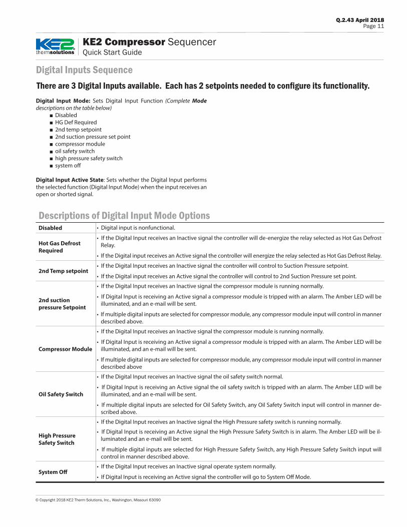
Digital Inputs Sequence
Digital Input mode: Sets Digital Input Function (Complete Mode descriptions on the table below)
Disabled HG Def Required 2nd temp setpoint 2nd suction pressure set point compressor module oil safety switch high pressure safety switch system off
Digital Input Active State: Sets whether the Digital Input performs the selected function (Digital Input Mode) when the input receives an open or shorted signal.
Descriptions of Digital Input Mode OptionsDisabled • Digital input is nonfunctional.
Hot gas Defrost Required
• If the Digital Input receives an Inactive signal the controller will de-energize the relay selected as Hot Gas Defrost Relay.
• If the Digital input receives an Active signal the controller will energize the relay selected as Hot Gas Defrost Relay.
2nd Temp setpoint• If the Digital Input receives an Inactive signal the controller will control to Suction Pressure setpoint.
• If the Digital input receives an Active signal the controller will control to 2nd Suction Pressure set point.
2nd suction pressure Setpoint
• If the Digital Input receives an Inactive signal the compressor module is running normally.
• If Digital Input is receiving an Active signal a compressor module is tripped with an alarm. The Amber LED will be illuminated, and an e-mail will be sent.
• If multiple digital inputs are selected for compressor module, any compressor module input will control in manner described above.
Compressor module
• If the Digital Input receives an Inactive signal the compressor module is running normally.
• If Digital Input is receiving an Active signal a compressor module is tripped with an alarm. The Amber LED will be illuminated, and an e-mail will be sent.
• If multiple digital inputs are selected for compressor module, any compressor module input will control in manner described above
Oil Safety Switch
• If the Digital Input receives an Inactive signal the oil safety switch normal.
• If Digital Input is receiving an Active signal the oil safety switch is tripped with an alarm. The Amber LED will be illuminated, and an e-mail will be sent.
• If multiple digital inputs are selected for Oil Safety Switch, any Oil Safety Switch input will control in manner de-scribed above.
High Pressure Safety Switch
• If the Digital Input receives an Inactive signal the High Pressure safety switch is running normally.
• If Digital Input is receiving an Active signal the High Pressure Safety Switch is in alarm. The Amber LED will be il-luminated and an e-mail will be sent.
• If multiple digital inputs are selected for High Pressure Safety Switch, any High Pressure Safety Switch input will control in manner described above.
System Off• If the Digital Input receives an Inactive signal operate system normally.
• If Digital Input is receiving an Active signal the controller will go to System Off Mode.
There are 3 Digital Inputs available. Each has 2 setpoints needed to configure its functionality.

© Copyright 2018 KE2 Therm Solutions, Inc., Washington, Missouri 63090
Q.2.43 April 2018Page 12
KE2 Compressor SequencerQuick Start Guide
Men
u Pa
ram
eter
s:
Man
ual C
ontr
olCl
ear A
larm
sFa
ctor
y Re
set
Web
Pas
swor
d Re
set
KE2
Smar
t Acc
ess
Mod
eD
HCP
Mod
e
Men
us:
Vari
able
sM
anua
l(v
iew
onl
y)
Non
-adj
usta
ble
Suct
ion
pres
sure
sen
sor a
larm
Suct
ion
tem
pera
ture
sen
sor a
larm
Dis
char
ge te
mpe
ratu
re s
enso
r ala
rmD
isch
arge
pre
ssur
e se
nsor
ala
rmAu
xilia
ry te
mpe
ratu
re s
enso
r ala
rmH
igh
suct
ion
supe
rhea
tLo
w s
uctio
n su
perh
eat
Low
dis
char
ge s
uper
heat
Hig
h di
scha
rge
pres
sure
Com
pres
sor m
odul
e al
arm
Oil
pres
sure
ala
rmSa
fety
sw
itch
trip
ped
T2 A
ux S
enso
r
Ala
rms
(vie
w o
nly)
Left
and
Rig
ht A
rrow
s - u
se to
mov
e be
twee
n M
enus
Up
Arr
ow a
nd D
own
Arr
ow -
scro
ll th
roug
h M
enu
Para
met
ers
ENTE
RPr
ess
and
hol
d EN
TER
for 3
sec
onds
, whe
n di
spla
y be
gins
bl
inki
ng c
hang
es c
an b
e m
ade
BACK
Pres
s BA
CK to
retu
rn to
the
prev
ious
vie
w.
ENTE
RPr
ess
and
hol
d EN
TER
for 3
sec
onds
to s
ave
chan
ge
To c
hang
e se
ttin
gs:
To s
ave
sett
ing
chan
ges:
To m
ove
thro
ugh
cont
rolle
r men
us:
To re
turn
to M
ain
Men
u:
Indi
cato
r lig
hts
Red
ligh
t - c
ritic
al a
larm
(sys
tem
is n
ot ru
nnin
g)
Am
ber/
Yello
w li
ght -
non
-crit
ical
ala
rm (s
yste
m ru
nnin
g)
Gre
en li
ght -
sys
tem
is ru
nnin
g
Su
ctio
n pr
essu
re
Cap
%
Com
pres
sor 1
rela
y
Com
pres
sor 2
rela
y
Com
pres
sor 3
rela
y
Com
pres
sor 4
rela
y
Com
pres
sor 5
rela
y
Supe
rhea
t
T1 s
uctio
n te
mp
Sa
tura
tion
Tem
pIn
t Com
p Te
mp
If T2
is S
elec
ted:
Dis
ch P
ress
D
isch
Sup
erhe
at
Dis
ch Te
mp
D
isch
Sat
Tem
pCa
p%D
ig 1
sta
tus
D
ig 2
sta
tus
D
ig 3
sta
tus
IP
Oct
et 1
IP
Oct
et 2
IP
Oct
et 3
IP
Oct
et 4
Su
bnet
Mas
k O
ctet
1
Subn
et M
ask
Oct
et 2
Su
bnet
Mas
k O
ctet
3
Subn
et M
ask
Oct
et 4
Fi
rmw
are
Vers
ion
ENTE
RPr
ess
ENTE
R to
go
from
par
amet
er to
val
ue.
To to
ggle
bew
een
desc
ript
ion
and
valu
e :
Suct
ion
Pres
sure
Cut O
ut P
ress
ure
2nd
Suct
ion
Pres
sure
Tem
p U
nits
Suc
Pres
s D
i�Re
frig
eran
t
* All
othe
r Set
poin
ts m
ust
be a
cces
sed
from
the
cont
rolle
r’s w
ebpa
ge.
Setp
oint
s*En
ter
Pass
wor
d
ther
mso
luti
ons
ENTE
R
BACK
Com
pres
sor
Sequ
ence
r
®
T2 M
onito
r
− o
r −
T2 In
tern
al C
omp
Tem
p
Controller Navigation
Cont
rolle
r Nav
igat
ion

Q.2.43 April 2018Page 13
© Copyright 2018 KE2 Therm Solutions, Inc., Washington, Missouri 63090
KE2 Compressor SequencerQuick Start Guide
Firs
t lin
e is
the
fu
nctio
n
Sec
ond
line
is t
he
curr
ent
syst
em
perf
orm
ance
For
each
Dis
play
s nu
mbe
r of
us
ers
curr
ently
vi
ewin
g th
is s
peci
fic
cont
rolle
r’s
web
page
.
Sys
tem
ala
rms
and
mes
sage
s ar
e di
spla
yed.
DES
CRIP
TIO
N:
Dis
play
s re
al ti
me
syst
em in
form
atio
n, a
nd s
how
s th
e in
tera
ctio
n of
mul
tiple
sys
tem
con
ditio
ns.
This
scr
een
look
s at
the
syst
em c
ondi
tions
, and
can
hel
p w
ith d
iagn
ostic
s, sy
stem
per
form
ance
, or
just
offe
r pea
ce o
f min
d th
at th
e sy
stem
is ru
nnin
g pr
oper
ly.
Home Page
Appendix AWebpages
Hom
e Pag
e

© Copyright 2018 KE2 Therm Solutions, Inc., Washington, Missouri 63090
Q.2.43 April 2018Page 14
KE2 Compressor SequencerQuick Start Guide
Bas
ic (P
ort
25
) K
E2 T
herm
Def
ault
Ser
ver
Upd
ate
firm
war
e.
Ref
er to
Q.5
.6 K
E2
Boo
tload
er G
uide
.
Site
and
Pas
swor
d m
ay b
e ch
ange
d by
cus
tom
er t
o cr
eate
a
uniq
ue K
E2 S
mar
t A
cces
s lo
gin
Sta
ndar
dS
iteV
iew
MA
NA
GER
Req
uire
d to
mak
e ch
ange
s to
S
ettin
gs p
age.
See
pag
e 1
5.
Rem
otel
y re
boot
s th
e co
ntro
ller.
Use
to v
erify
pro
per
e-m
ail
conf
igur
atio
n. C
lick
Save
but
ton
(bot
tom
rig
ht o
f pag
e) b
efor
e te
stin
g
Rem
oves
all
data
st
ored
by
cont
rolle
r. D
o no
t use
unl
ess
inst
ruct
ed to
by
KE2
Th
erm
.
Res
ets
cont
rolle
r’s
alar
ms
and
alar
m
cond
ition
s.
Cus
tom
er in
form
atio
n is
di
spla
yed
Use
to
cust
omiz
e th
e U
ser
Nam
e an
d P
assw
ord
from
the
de
faul
t se
ttin
g.
The
KE2
Sm
art
Acc
ess
Set
tings
are
pr
ovid
ed b
y K
E2 T
herm
, and
are
onl
y ne
eded
whe
n us
ing
KE2
The
rm’s
cus
tom
er
port
al fo
r ac
cess
ing
the
cont
rolle
r
Use
to
veri
fy
prop
er A
PI
conf
igur
atio
n
Use
r de
fines
co
ntro
ller
loca
tion
for
futu
re a
cces
s. K
E2
Sm
art
Acc
ess
and
alar
m n
otifi
catio
ns
Cus
tom
er m
ay in
put
thei
r co
mpa
ny in
form
atio
n
Ente
r e-
mai
l add
ress
an
d su
bjec
t for
ale
rts.
DES
CRIP
TIO
N:
The
Sett
ings
pag
e co
ntai
ns c
ontr
olle
r con
figur
atio
n fo
r e-m
ail a
nd w
eb a
cces
s.
It al
so a
llow
s ins
talle
rs to
cus
tom
ize
the
Mas
terV
iew
with
thei
r com
pany
info
rmat
ion.
The
Set
tings
pa
ge in
clud
es t
he b
utto
ns t
o up
date
the
con
trol
ler,
rese
t po
wer
to
the
cont
rolle
r, se
nd a
tes
t e-
mai
l, cl
ear d
ata
colle
cted
, and
cle
ar a
larm
s.
Settings Page
Appendix AWebpages
Setti
ngs P
age

Appendix AWebpages
Q.2.43 April 2018Page 15
© Copyright 2018 KE2 Therm Solutions, Inc., Washington, Missouri 63090
KE2 Compressor SequencerQuick Start Guide
To m
ake
chan
ges
to t
he S
ettin
gs p
age,
Net
wor
k pa
ge a
nd S
etpo
ints
pa
ge t
he U
ser
Nam
e an
d P
assw
ord
mus
t be
pro
vide
d.
The
defa
ult
Use
r N
ame:
ke2
adm
in
Th
e de
faul
t P
assw
ord:
ke2
adm
in
For
secu
rity
rea
sons
, the
Use
r N
ame
and
Pas
swor
d sh
ould
be
chan
ged
from
the
def
ault.
Onc
e yo
u ar
e lo
gged
in, g
o to
the
S
ettin
gs p
age
to c
hang
e th
e U
ser
Nam
e an
d P
assw
ord.
DES
CRIP
TIO
N:
The
Logi
n fe
atur
e pr
even
ts u
naut
horiz
ed a
cces
s to
the
cont
rolle
r.
The
user
mus
t en
ter
the
pass
wor
d to
mak
e ch
ange
s to
the
Set
tings
pag
e, N
etw
ork
page
, and
Se
tpoi
nts
page
.
Login Page
Logi
n Pa
ge

Appendix AWebpages
© Copyright 2018 KE2 Therm Solutions, Inc., Washington, Missouri 63090
Q.2.43 April 2018Page 16
KE2 Compressor SequencerQuick Start Guide
IP A
ddre
ss m
ay
be c
hang
ed to
m
atch
the
onsi
te
netw
ork.
Typ
ical
ly th
e su
bnet
mas
k,
gate
way
and
pr
imar
y D
NS
shou
ld a
lso
be
chan
ged.
Net
wor
k se
ttin
gs m
ay b
e ch
ange
d to
mat
ch c
usto
mer
’s
envir
onm
ent.
IP a
ddre
ss is
Ena
bled
or
Dis
able
dEn
able
d - i
f sel
ecte
d IP
is D
ynam
icD
isab
led
- if s
elec
ted
IP is
Sta
tic
Pre
vent
s un
auth
oriz
ed a
cces
s to
the
co
ntro
ller.
Use
r m
ust
ente
r U
ser
Nam
e an
d P
assw
ord
to m
ake
chan
ges
to t
he N
etw
ork
Set
up p
age.
Sav
es c
hang
es t
o th
e co
ntro
ller’
s ne
twor
k.
DES
CRIP
TIO
N:
Prov
ides
set
up fo
r add
ing
cont
rolle
rs to
an
exis
ting
cust
omer
net
wor
k.
Network Page
Netw
ork P
age

Appendix AWebpages
Q.2.43 April 2018Page 17
© Copyright 2018 KE2 Therm Solutions, Inc., Washington, Missouri 63090
KE2 Compressor SequencerQuick Start Guide
Act
ive
whe
n O
pen
(i.e.
doo
r op
en)
Act
ive
whe
n C
lose
d
Dig
In 1
, 2 o
r 3
Mod
e D
isab
led
HG
Def
r R
eq2
nd T
emp
2nd
Pre
sC
omp
Mod
ule
Oil
Saf
ety
Sw
Hi P
res
Sw
itch
Sys
Off
Dig
ital
Inpu
ts
Rel
ay 1
D
ropd
own
Opt
ions
HG
Def
r R
elay
LLS
Var
iabl
e S
peed
Unl
dr fo
r C
omp
2U
nldr
for
Com
p 3
Unl
dr fo
r C
omp
4U
nldr
for
Com
p 5
Rel
ay 2
- 5
Dro
pdow
n O
ptio
nsA
ll R
elay
Opt
ions
the
sa
me
as R
elay
1,
exce
pt t
he li
st o
f U
nloa
ders
for
the
com
pres
sor
neve
r in
clud
es t
he a
ctiv
e co
mpr
esso
r.
R-4
04
AR
-50
7R
-40
7A
R-4
07
CR
-42
2A
R-4
22
DR
-13
4a
R-2
2
R-7
17
R-4
38
AR
-40
8A
R-4
09
AR
-40
7F
R-4
10
AR
-74
4
Fahr
enhe
it C
elsi
usD
isab
led
T2 M
onito
rT2
Roo
m T
emp
Int
Com
p Te
mp
DES
CRIP
TIO
N:
Allo
ws
the
user
to s
etup
the
cont
rolle
r, an
d to
cus
tom
ize
the
cont
rolle
r to
mee
t spe
cific
ap
plic
atio
n ne
eds.
The
KE2
Com
pres
sor S
eque
ncer
beg
ins
in S
yste
m O
ff M
ode.
The
use
r mus
t con
figur
e re
lays
and
re
frig
erat
ion
setp
oint
s to
ens
ure
the
syst
em ru
ns p
rope
rly, t
hen
turn
the
syst
em o
n.
Setpoints Page
Setp
oint
s Pag
e

Appendix AWebpages
© Copyright 2018 KE2 Therm Solutions, Inc., Washington, Missouri 63090
Q.2.43 April 2018Page 18
KE2 Compressor SequencerQuick Start Guide
The
Site
Vie
w s
how
s a
live
view
of e
ach
cont
rolle
r’s
perf
or-
man
ce
Whe
n th
e co
ntro
llers
ar
e in
the
sam
e ne
twor
k, c
licki
ng o
n th
e co
ntro
ller’
s lo
catio
n w
ill
open
the
web
page
of
that
con
trol
ler.
Each
mem
ber
is
view
ed b
y cl
icki
ng o
n th
e lo
catio
n na
me
in
the
Site
Vie
w M
aste
r’s
list.
The
Site
Vie
w M
aste
r m
ay c
onta
in u
p to
49
m
embe
rs. A
ll m
em-
bers
mus
t be
in t
he
sam
e ne
twor
k. i.
e. a
ro
uter
div
ides
a
netw
ork.
The
Site
Vie
w m
ay b
e or
gani
zed
by lo
ggin
g in
to t
he c
ontr
olle
r.
Air
/ E
lect
ric
Hot
Gas
DES
CRIP
TIO
N:
Site
View
pro
vide
s th
e ab
ility
to s
etup
mul
tipl
e co
ntro
llers
in th
e sa
me
netw
ork
into
def
rost
gr
oups
to m
anag
e th
e co
ncur
rent
def
rost
load
by
sett
ing
Capa
city
, gro
up, a
nd D
efro
st
Type
. If t
he u
ser n
eeds
mor
e de
taile
d in
form
atio
n, o
r to
mak
e ad
just
men
ts,
clic
king
on
the
nam
e of
the
cont
rolle
r, sh
own
in th
e Lo
cati
on c
olum
n, w
ill o
pen
the
Hom
e Pa
ge o
f tha
t con
trol
ler.
Hot
Gas
mus
t be
sele
cted
for K
E2 C
ompr
esso
r Seq
uenc
er to
ene
rgiz
e th
e H
ot G
as D
efro
st R
elay
.
SiteView Page
Site
View
Pag
e

Q.2.43 April 2018Page 19
© Copyright 2018 KE2 Therm Solutions, Inc., Washington, Missouri 63090
KE2 Compressor SequencerQuick Start Guide
Exam
ple:
5
.46
0
Cap
Loa
d10
0
Suc
t P
res
11
.4
Wee
kly
view
Mon
thly
vie
w*
Cur
rent
act
ivity
Wri
tes
the
data
sto
red
on t
he
cont
rolle
r to
a C
SV
file
.*
Dat
e an
d Ti
me
are
pulle
d fr
om t
he c
onne
cted
co
mpu
ter.
5.46
0
Day
, Cap
acity
Loa
d, a
nd
Suc
tion
Pre
ssur
e ar
e di
spla
yed
whe
n m
ovin
g th
e m
ouse
ove
r th
e da
ta.
Day
s ag
o
DES
CRIP
TIO
N:
The
Gra
phin
g Sn
apsh
ot s
how
s th
e pa
st s
even
day
s of
Cap
acity
Loa
d an
d Su
ctio
n Pr
essu
re
read
ings
. It i
s an
ess
entia
l too
l for
sys
tem
ana
lysi
s an
d tr
oubl
esho
otin
g.
The
expe
rts
at K
E2 Te
chni
cal S
uppo
rt c
an h
elp
trou
bles
hoot
you
r sys
tem
usi
ng th
is in
form
atio
n
Graphs Page
Appendix AWebpages
Grap
hs P
age

© Copyright 2018 KE2 Therm Solutions, Inc., Washington, Missouri 63090
Q.2.43 April 2018Page 20
KE2 Compressor SequencerQuick Start Guide
KE2 Therm Solutions 12 Chamber Drive . Washington, MO 63090
1.888.337.3358 . www.ke2therm.com
Enter default information and click Log In button Site: installerPassword: controller’s Mac Address (from sticker on back of controller)
Enable KE2 Smart Access in the Setpoints menu After the initial Introduction Mode setup, press the arrow
to get to Manual Menu.
Press ENTER and the controller will display Enter Password.
Press ENTER and (4) zeros will appear. Use the and
to enter 2222
Press and hold ENTER for 3 seconds.
Press until Smart Access Mode is displayed
Press ENTER and Disabled will be displayed.
Press & hold ENTER for 3 seconds. Red & Amber LEDs will blink.
Press and Enabled will be displayed.
Press & hold ENTER for 3 seconds. Red & Amber LEDs will stop blinking.
go to smartaccess.ke2therm.net
Using your PC, tablet or smartphone, enter http://smartaccess.ke2therm.net in the web browser’s address bar.
KE2 Smart Access - Online Access In 3 Easy Steps
For additional information on KE2 Smart Access, visit:http://ke2therm.com/literature/literature-ke2-smartaccess/See Q.1.34 KE2 Smart Access Setup and Customizing and A.5.89 Purchasing a KE2 Smart Access License.
Introduction to KE2 Smart AccessKE2 Smart Access provides quick and easy, real time access to your refrigera-tion systems, 24/7
Now it’s easier than ever to monitor and adjust your KE2 Compressor Se-quencer remotely. While the KE2 Compressor Sequencer’s free connectiv-ity is still available, KE2 Therm recognizes that some customers prefer the simplicity and convenience of KE2 Smart Access to enjoy the benefits of the controller’s communication capability.
For a nominal monthly fee, KE2 Smart Access provides easy, real time ac-cess to your refrigeration system 24/7. No port forwarding. No VPN.
All the KE2 Compressor Sequencer needs is a physical connection to the network router. Once enabled, KE2 Smart Access quickly connects to your personal web portal, hosted by KE2 Therm, and provides a “customized” dashboard of all the controllers you setup with KE2 Smart Access.
Preliminary Connect the KE2 Compressor Sequencer to the customer’s network.
CAT5 Ethernet Cable
1 2 3 654 7
Link/ACT
100/1000MbpsPOWER
Customer Network
thermsolutions
ENTER
BACK
CompressorSequencer
®
Setup the controller by going to the Setpoints page.
Screen shot of a single KE2 Compressor Sequencer connected through KE2 Smart Access.
Screen shots of KE2 Smart Access dashboard. Controller and system information is displayed for all of the controllers on the portal.
Benefits of KE2 Smart Access KE2 Smart Access auto launches, and often eliminates costly IT support
Doesn’t require port forwarding or a vpn
Customized dashboard lets you view all your controllers on one page
It’s easier than ever to set up every controller you service to provide alarm notifications via text or e-mail
Easy setup of remote monitoring & system control
youtube.com/ke2thermVisit our youTube channel for videos on KE2 Smart Access.
Step 3
Step 2
Step 1
IP-10.10.52.19MAC
00:04:A3:14:E5:92
IP-10.10.52.19MAC
00:04:A3:14:E5:92
installer
Appendix BKE2 Smart Access