Embed Size (px)
Citation preview
16-Nov-02USITT Hydraulics TV Korder 2
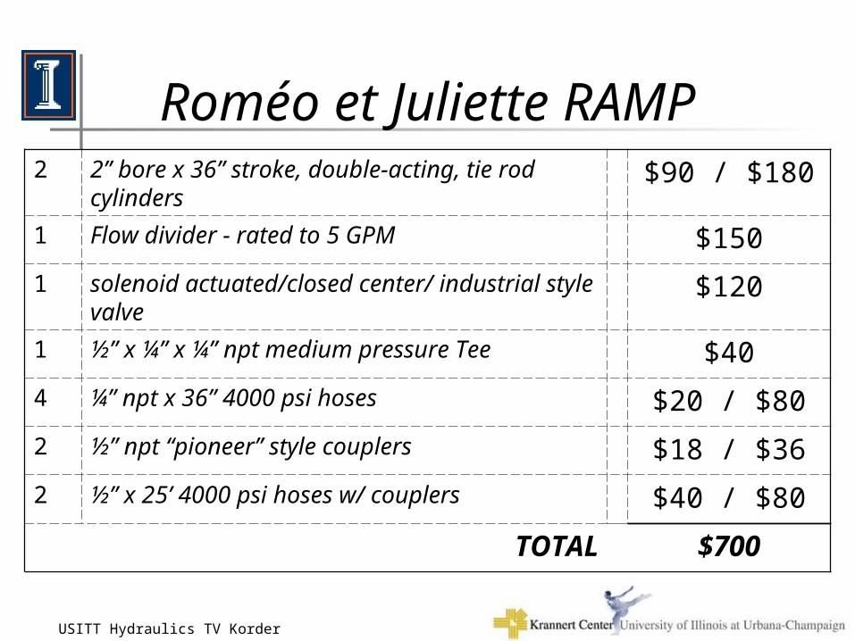
Roméo et Juliette RAMP
• Two –
• One –, rated up to 5 GPM
• One – One –
2 2” bore x 36” stroke, double-acting, tie rod cylinders
$90 / $180
1 Flow divider - rated to 5 GPM $150
1 solenoid actuated/closed center/ industrial style valve
$120
1 ½” x ¼” x ¼” npt medium pressure Tee $40
4 ¼” npt x 36” 4000 psi hoses $20 / $80
2 ½” npt “pioneer” style couplers $18 / $36
2 ½” x 25’ 4000 psi hoses w/ couplers $40 / $80
TOTAL $700
16-Nov-02USITT Hydraulics TV Korder 3
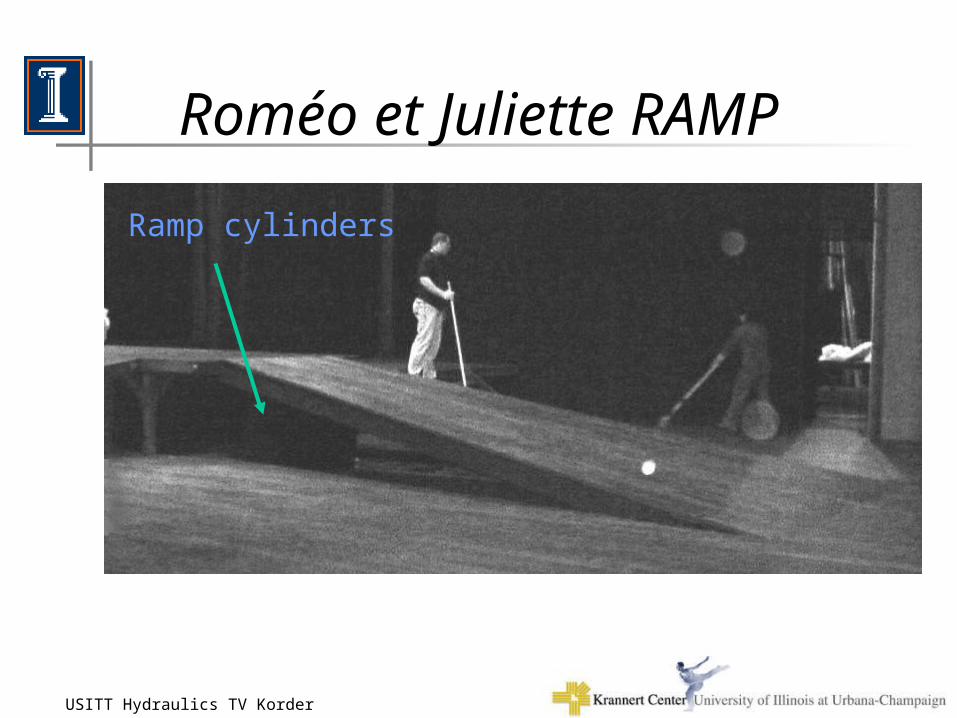
Ramp cylinders
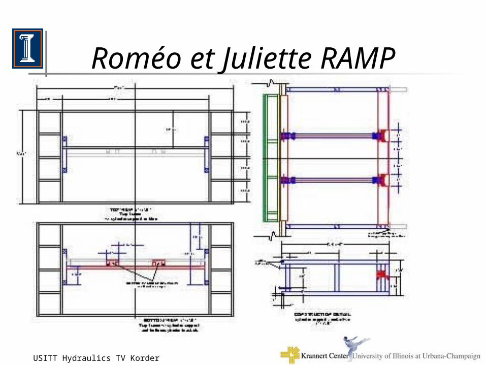
Roméo et Juliette RAMP
16-Nov-02USITT Hydraulics TV Korder 4
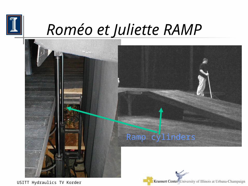
Ramp cylinders
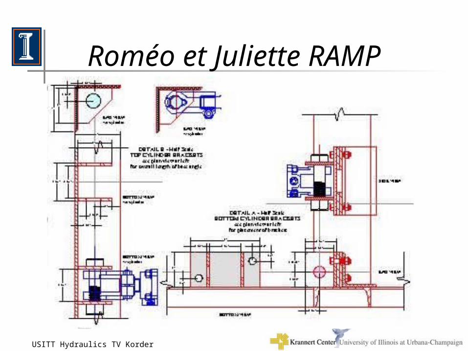
Roméo et Juliette RAMP
16-Nov-02USITT Hydraulics TV Korder 5
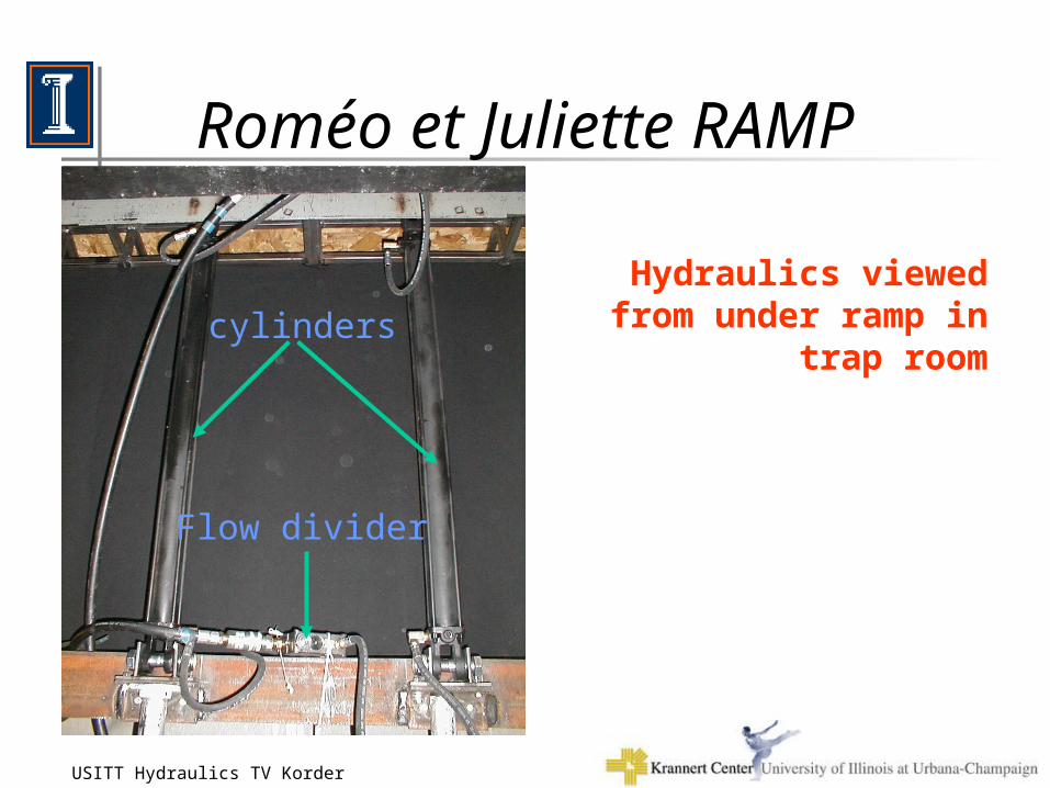
cylinders
Flow divider
Roméo et Juliette RAMP
Hydraulics viewed from under ramp in trap room
16-Nov-02USITT Hydraulics TV Korder 6
Roméo et Juliette RAMP
16-Nov-02USITT Hydraulics TV Korder 7
Roméo et Juliette RAMP
16-Nov-02USITT Hydraulics TV Korder 8
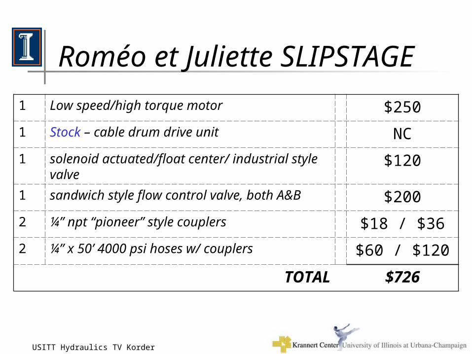
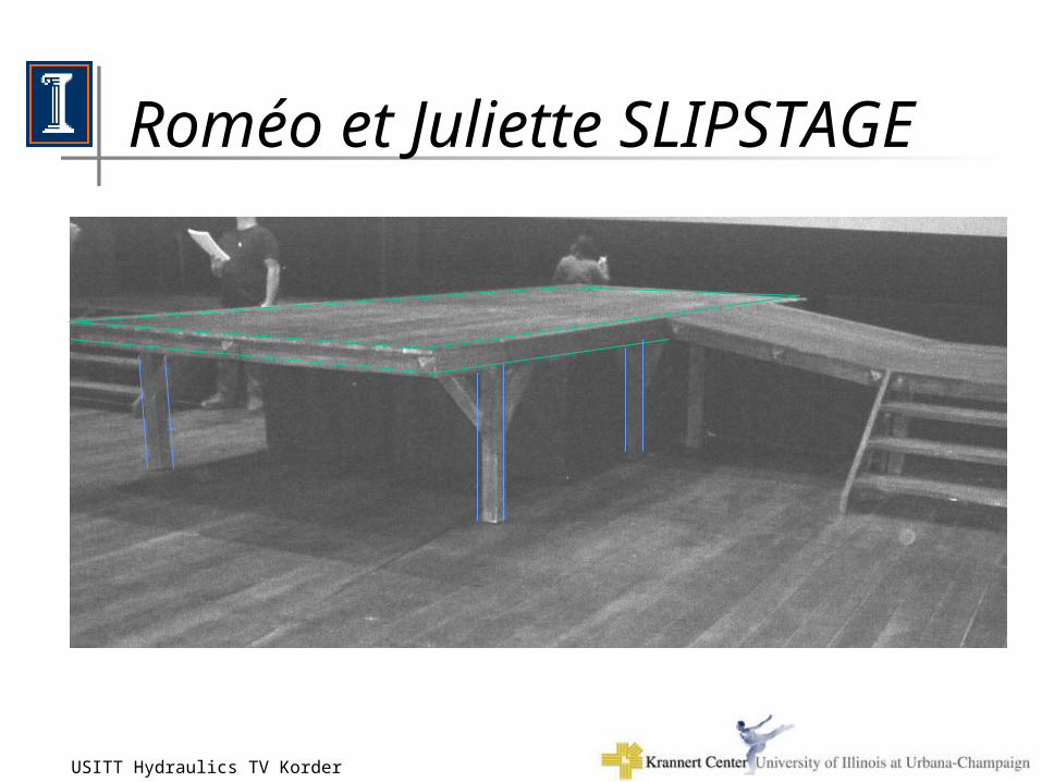
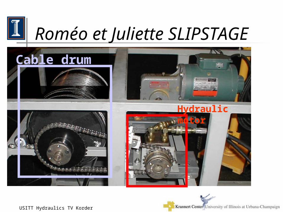
Roméo et Juliette SLIPSTAGE
• Two –
• One –, rated up to 5 GPM
• One – One –
1 Low speed/high torque motor $250
1 Stock – cable drum drive unit NC
1 solenoid actuated/float center/ industrial style valve $120
1 sandwich style flow control valve, both A&B $200
2 ¼” npt “pioneer” style couplers $18 / $36
2 ¼” x 50’ 4000 psi hoses w/ couplers $60 / $120
TOTAL $726
16-Nov-02USITT Hydraulics TV Korder 9
Roméo et Juliette SLIPSTAGE

16-Nov-02USITT Hydraulics TV Korder 10
Roméo et Juliette SLIPSTAGE
Slipstage in “out” position
16-Nov-02USITT Hydraulics TV Korder 11
Roméo et Juliette SLIPSTAGE
Cable drum
Hydraulic motor
16-Nov-02USITT Hydraulics TV Korder 12
Shop-Built Hydraulic Trainer• AC Power Unit (500 psi, 1-2 gpm)• Tie-rod and industrial cylinders• Low speed/high torque motor• Rotary Actuator• Industrial and Mobile valves
– different actuations and centers
• Flow, pressure, etc. valves– sandwich and in-line style
• Pressure gauges and flow meter• Hoses with couplers, adapters
16-Nov-02USITT Hydraulics TV Korder 13
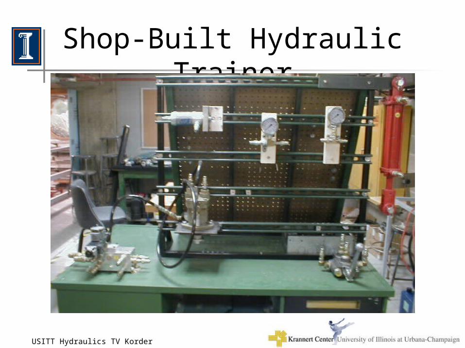
Shop-Built Hydraulic Trainer
16-Nov-02USITT Hydraulics TV Korder 14
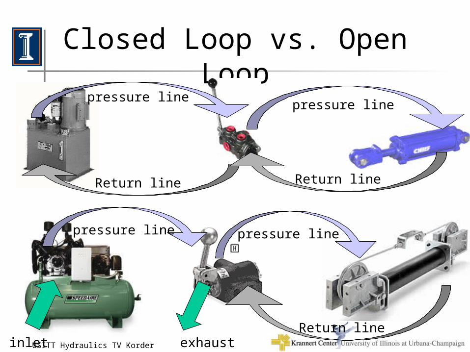
Closed Loop vs. Open Loop
Return line Return line
exhaustinlet
pressure linepressure line
pressure linepressure line
Return line
16-Nov-02USITT Hydraulics TV Korder 15
DESIGNING A SYSTEM
A. Determine System Parameters
B. Perform System Calculations
C. Choose System Components
16-Nov-02USITT Hydraulics TV Korder 16
A. System Parameters
• What type of movement? (Linear or Rotary)– actuator type
• How far does it travel?– Stroke, degree of rotation
• How heavy is the object ?– total weight of all materials
• What speed?– How fast of move? safe travel speed ?– How fast to get to full speed? , rpm
• Other needed components?
16-Nov-02USITT Hydraulics TV Korder 17
B. System Calculations
• FORCE / TORQUE– lbs of force– in lbs of torque
• SPEED / FLOW– time for stroke– time for rotation
16-Nov-02USITT Hydraulics TV Korder 18
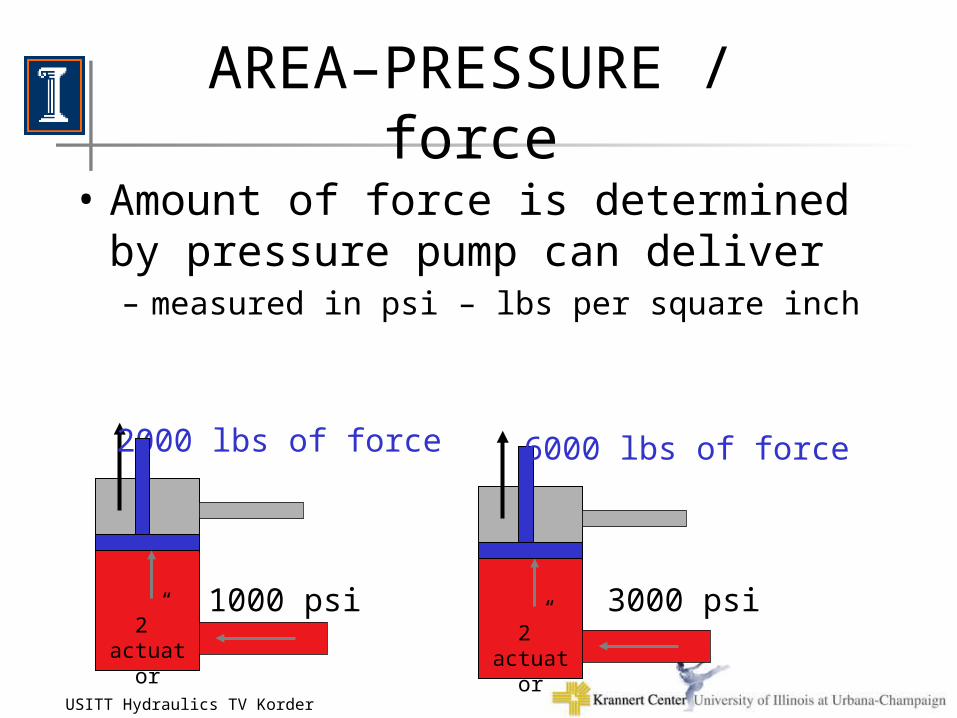
AREA–PRESSURE / force
• Amount of force is determined by pressure pump can deliver– measured in psi – lbs per square inch
2”actuato
r
1000 psi 3000 psi
2000 lbs of force
2”actuato
r
6000 lbs of force
16-Nov-02USITT Hydraulics TV Korder 19
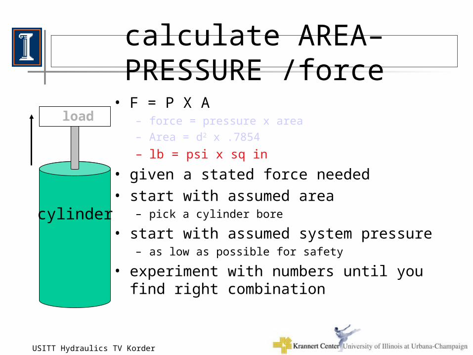
calculate AREA–PRESSURE /force
• F = P X A– force = pressure x area
– Area = d2 x .7854
– lb = psi x sq in
• given a stated force needed
• start with assumed area– pick a cylinder bore
• start with assumed system pressure– as low as possible for safety
• experiment with numbers until you find right combination
cylinder
load
16-Nov-02USITT Hydraulics TV Korder 20
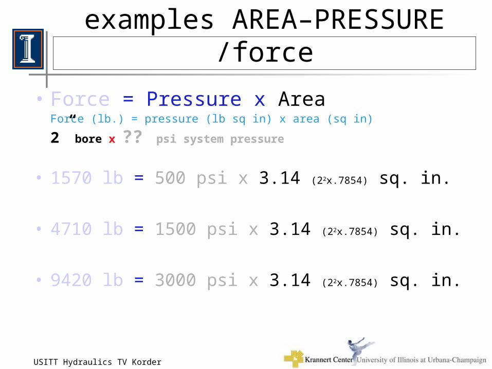
examples AREA–PRESSURE /force
• Force = Pressure x AreaForce (lb.) = pressure (lb sq in) x area (sq in)
2” bore x ?? psi system pressure
• 1570 lb = 500 psi x 3.14 (22x.7854) sq. in.
• 4710 lb = 1500 psi x 3.14 (22x.7854) sq. in.
• 9420 lb = 3000 psi x 3.14 (22x.7854) sq. in.
16-Nov-02USITT Hydraulics TV Korder 21
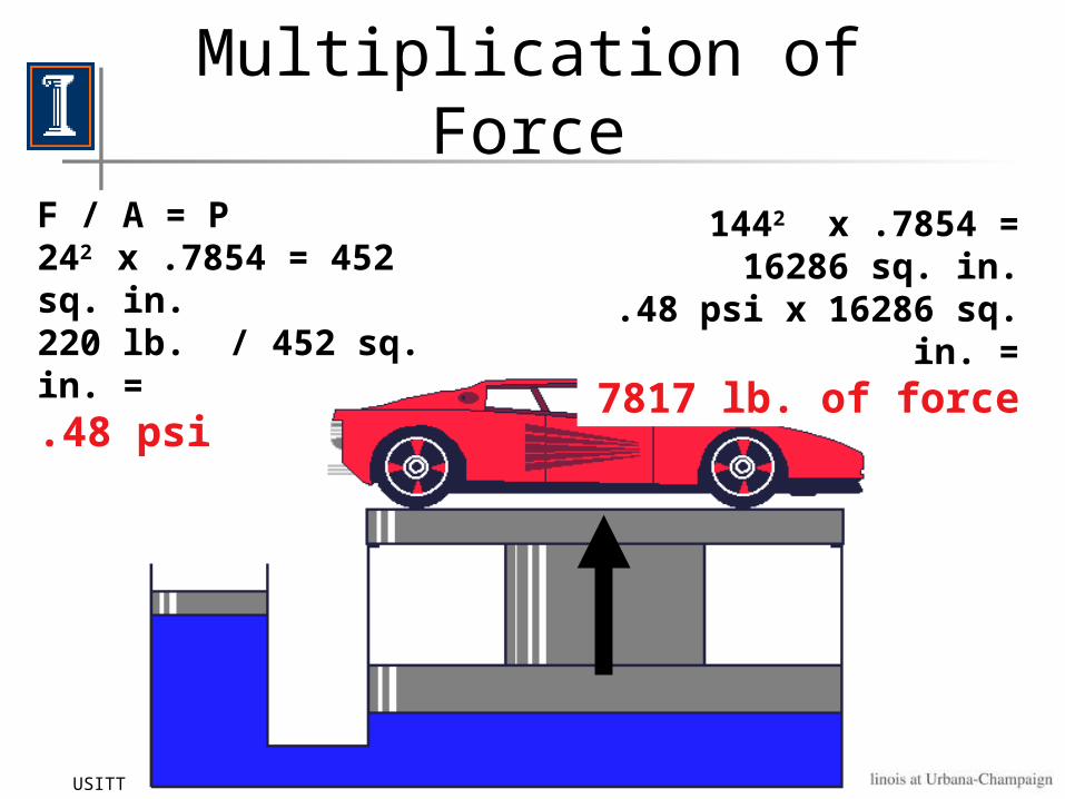
Multiplication of Force
F / A = P242 x .7854 = 452 sq. in.220 lb. / 452 sq. in. = .48 psi
1442 x .7854 = 16286 sq. in..48 psi x 16286 sq. in. =
7817 lb. of force
16-Nov-02USITT Hydraulics TV Korder 22
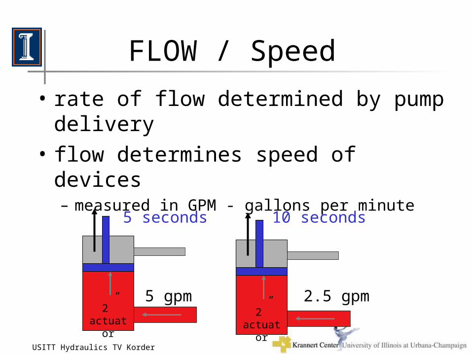
FLOW / Speed
• rate of flow determined by pump delivery
• flow determines speed of devices– measured in GPM - gallons per minute
2”actuato
r
5 gpm 2.5 gpm
5 seconds
2”actuato
r
10 seconds
16-Nov-02USITT Hydraulics TV Korder 23
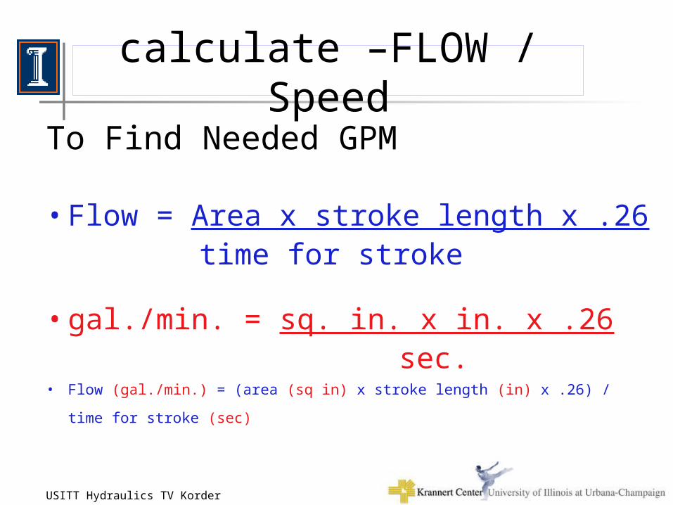
calculate –FLOW / Speed
To Find Needed GPM
• Flow = Area x stroke length x .26 time for stroke
• gal./min. = sq. in. x in. x .26 sec.
• Flow (gal./min.) = (area (sq in) x stroke length (in) x .26) / time for stroke (sec)
16-Nov-02USITT Hydraulics TV Korder 24
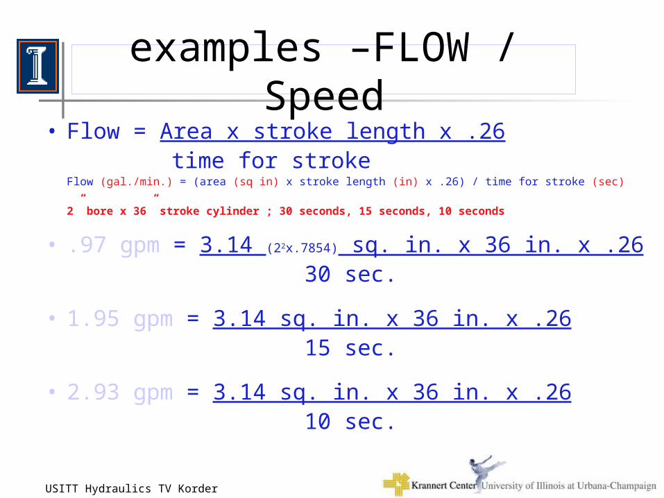
examples –FLOW / Speed• Flow = Area x stroke length x .26
time for strokeFlow (gal./min.) = (area (sq in) x stroke length (in) x .26) / time for stroke (sec)
2” bore x 36” stroke cylinder ; 30 seconds, 15 seconds, 10 seconds
• .97 gpm = 3.14 (22x.7854) sq. in. x 36 in. x .26 30 sec.
• 1.95 gpm = 3.14 sq. in. x 36 in. x .26 15 sec.
• 2.93 gpm = 3.14 sq. in. x 36 in. x .26 10 sec.
16-Nov-02USITT Hydraulics TV Korder 25
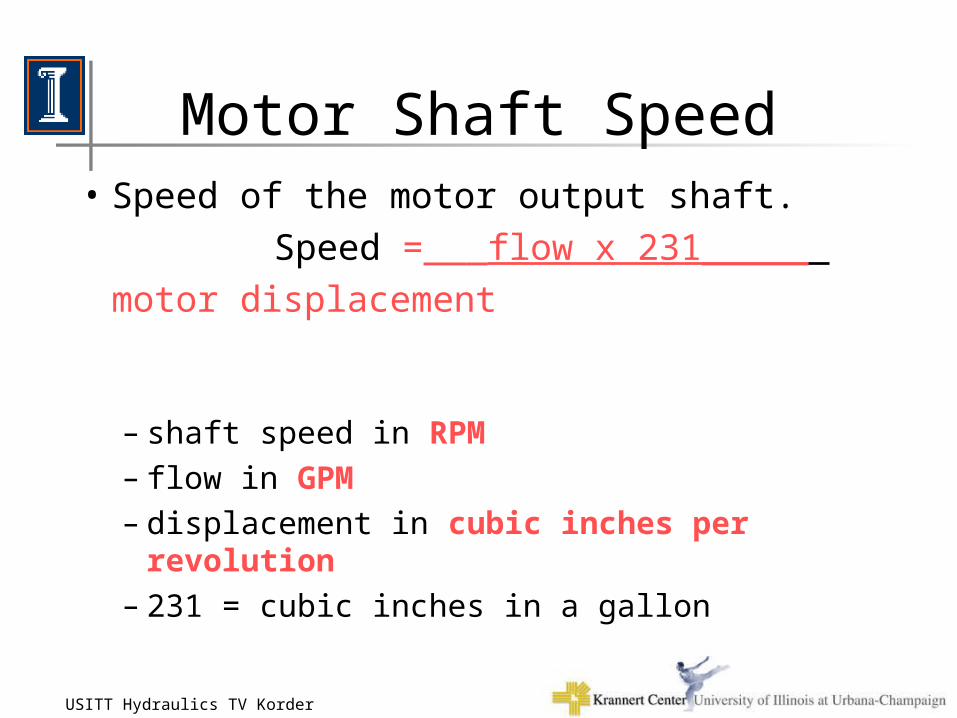
Motor Shaft Speed• Speed of the motor output shaft.
Speed =___flow x 231_____
motor displacement – shaft speed in RPM– flow in GPM– displacement in cubic inches per revolution– 231 = cubic inches in a gallon
16-Nov-02USITT Hydraulics TV Korder 26
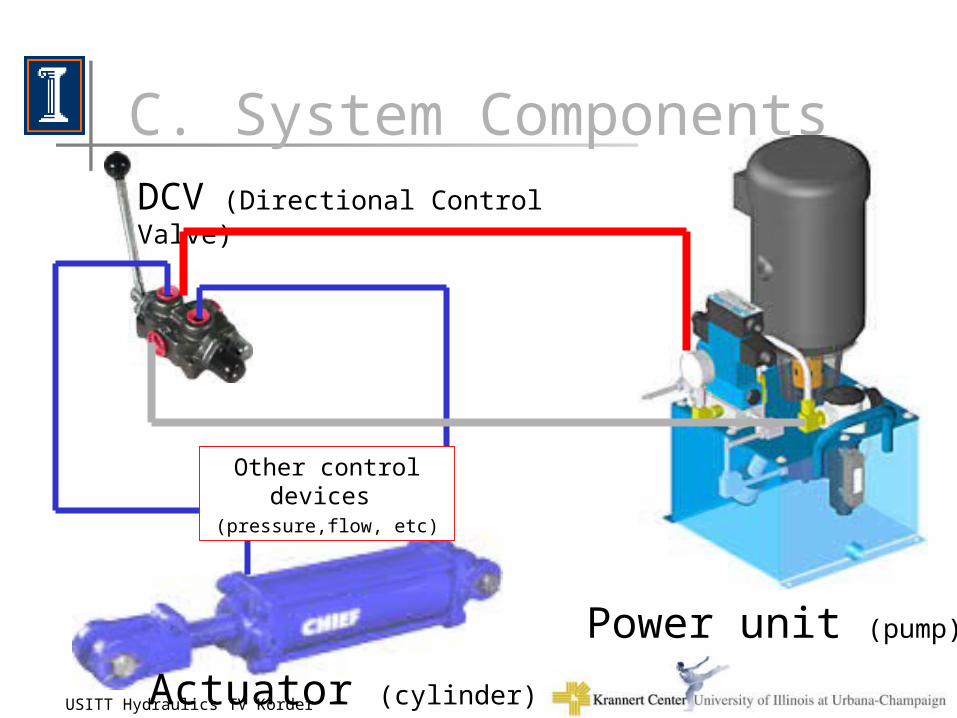
DCV (Directional Control Valve)
C. System Components
Power unit (pump)
Actuator (cylinder)
Other control devices
(pressure,flow, etc)
16-Nov-02USITT Hydraulics TV Korder 27
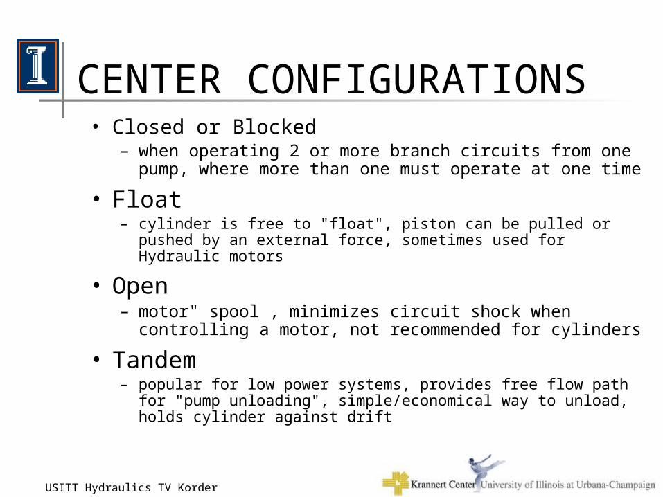
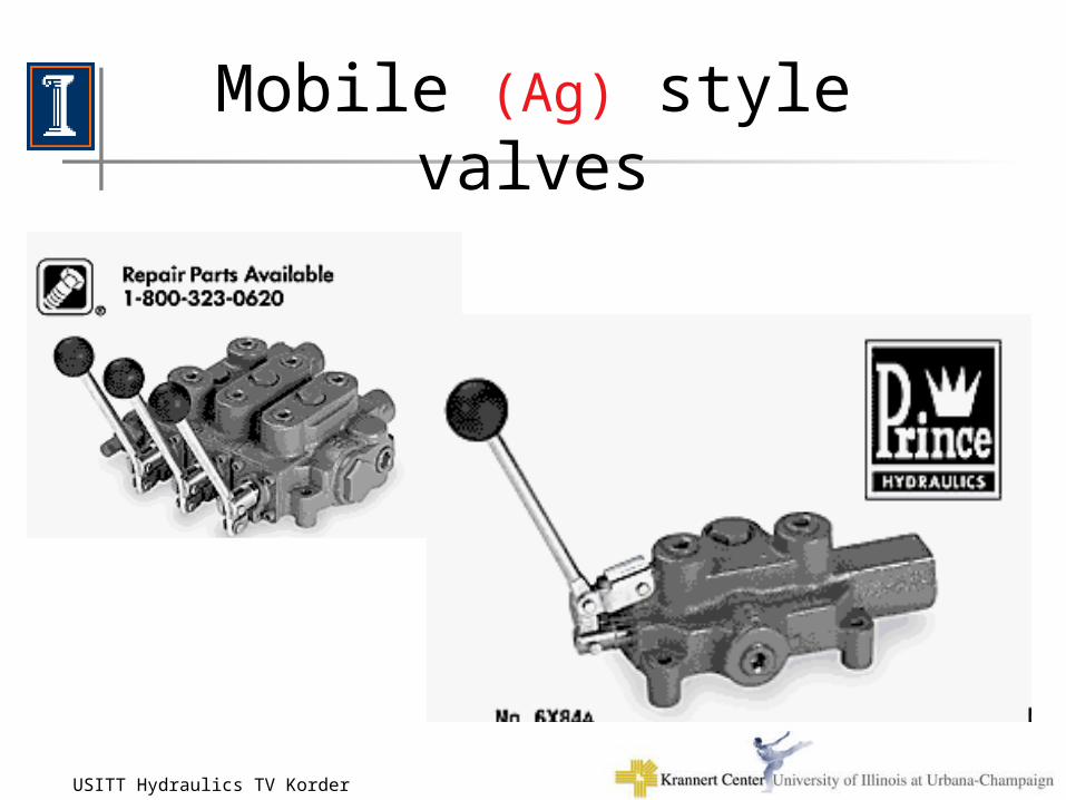
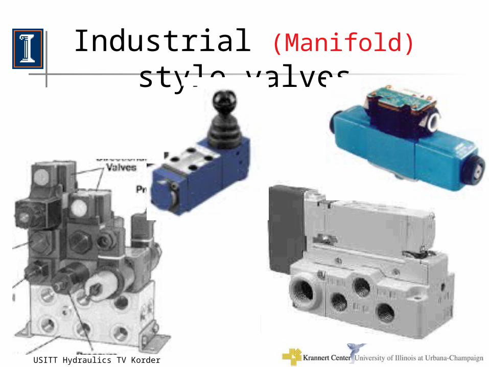
MOBILE vs. INDUSTRIAL• Industrial
– closer tolerances, more expensive, valves are modular
• Mobile– also known as agricultural, rugged/basic
construction, more plumbing/hoses, less expensive
• Suggestion– Mobile actuators, Industrial valves
16-Nov-02USITT Hydraulics TV Korder 28
POWER UNIT• Preassembled vs. Shop assembled• System Flow
– GPM – gallons per minute
• System Pressure– psi – pounds per square inch
• Voltage– 110vac or 220vac– 1 or 3
• Reservoir size– gallons
16-Nov-02USITT Hydraulics TV Korder 29
DCV directional control valve
• Actuation method– manual, electrical, or fluid
• Rating– flow and pressure
• Center style– closed, open, float, or tandem
• Style of construction– mobile or industrial
16-Nov-02USITT Hydraulics TV Korder 30
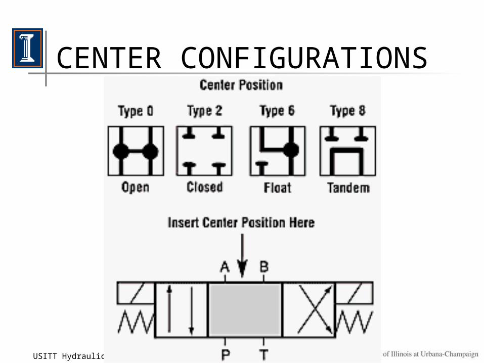
CENTER CONFIGURATIONS
16-Nov-02USITT Hydraulics TV Korder 31
CENTER CONFIGURATIONS• Closed or Blocked
– when operating 2 or more branch circuits from one pump, where more than one must operate at one time
• Float– cylinder is free to "float", piston can be pulled or pushed by an external
force, sometimes used for Hydraulic motors
• Open– motor" spool , minimizes circuit shock when controlling a motor,
not recommended for cylinders
• Tandem– popular for low power systems, provides free flow path for "pump
unloading", simple/economical way to unload, holds cylinder against drift
16-Nov-02USITT Hydraulics TV Korder 32
Mobile (Ag) style valves
16-Nov-02USITT Hydraulics TV Korder 33
Industrial (Manifold) style valves
16-Nov-02USITT Hydraulics TV Korder 34
ACTUATOR
• Action Needed– Linear, Rotary limited motion, Rotary continuous motion
• Amount of action needed – stroke length, degree of rotation, speed
• Force in both directions or only one
• Force / Speed– Bore/Displacement, Pressure, GPM rating, Port sizes
• Mounting Method
16-Nov-02USITT Hydraulics TV Korder 35
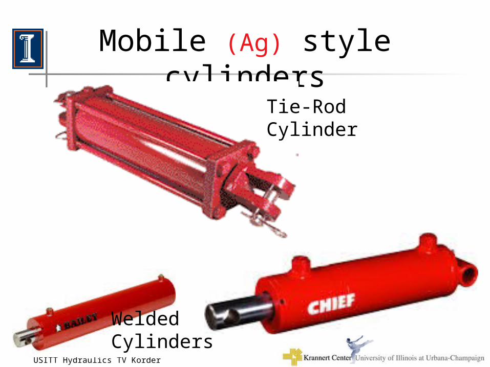
Mobile (Ag) style cylinders
Welded Cylinders
Tie-Rod Cylinder
16-Nov-02USITT Hydraulics TV Korder 36
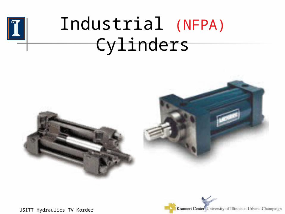
Industrial (NFPA) Cylinders
16-Nov-02USITT Hydraulics TV Korder 37
OTHER CONTROL DEVICES
• Pressure Control (force)
• Flow Control (speed)
• Additional controls– Safety Devices– Additional filtering– Electrics/Electronics– Counterbalancing– Flow dividing
16-Nov-02USITT Hydraulics TV Korder 38
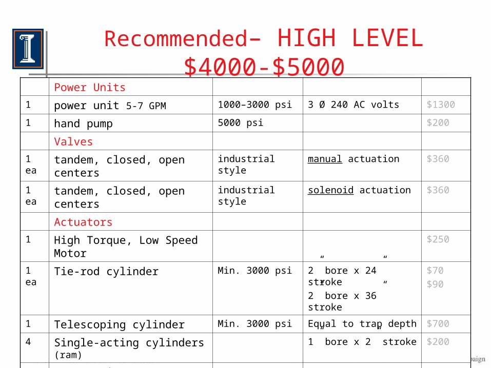
Recommended– HIGH LEVEL $4000-$5000
Power Units
1 power unit 5-7 GPM 1000–3000 psi 3 Ø 240 AC volts $1300
1 hand pump 5000 psi $200
Valves
1 ea tandem, closed, open centers industrial style manual actuation $360
1 ea tandem, closed, open centers industrial style solenoid actuation $360
Actuators
1 High Torque, Low Speed Motor $250
1 ea Tie-rod cylinder Min. 3000 psi 2” bore x 24” stroke
2” bore x 36” stroke
$70
$90
1 Telescoping cylinder Min. 3000 psi Equal to trap depth $700
4 Single-acting cylinders (ram) 1” bore x 2” stroke $200
Accessories
stack style valves counterbalance flow, pressure $500
Hoses with connectors $250
16-Nov-02USITT Hydraulics TV Korder 39
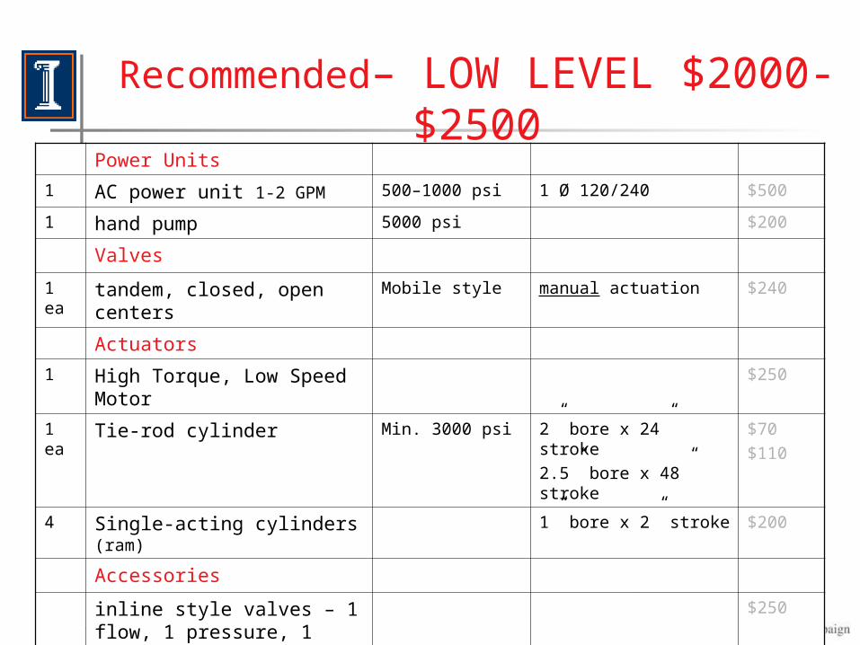
Recommended– LOW LEVEL $2000-$2500Power Units
1 AC power unit 1-2 GPM 500–1000 psi 1 Ø 120/240 $500
1 hand pump 5000 psi $200
Valves
1 ea tandem, closed, open centers Mobile style manual actuation $240
Actuators
1 High Torque, Low Speed Motor $250
1 ea Tie-rod cylinder Min. 3000 psi 2” bore x 24” stroke
2.5” bore x 48” stroke
$70
$110
4 Single-acting cylinders (ram) 1” bore x 2” stroke $200
Accessories
inline style valves – 1 flow, 1 pressure, 1 counterbalance
$250
Hoses $250
16-Nov-02USITT Hydraulics TV Korder 40
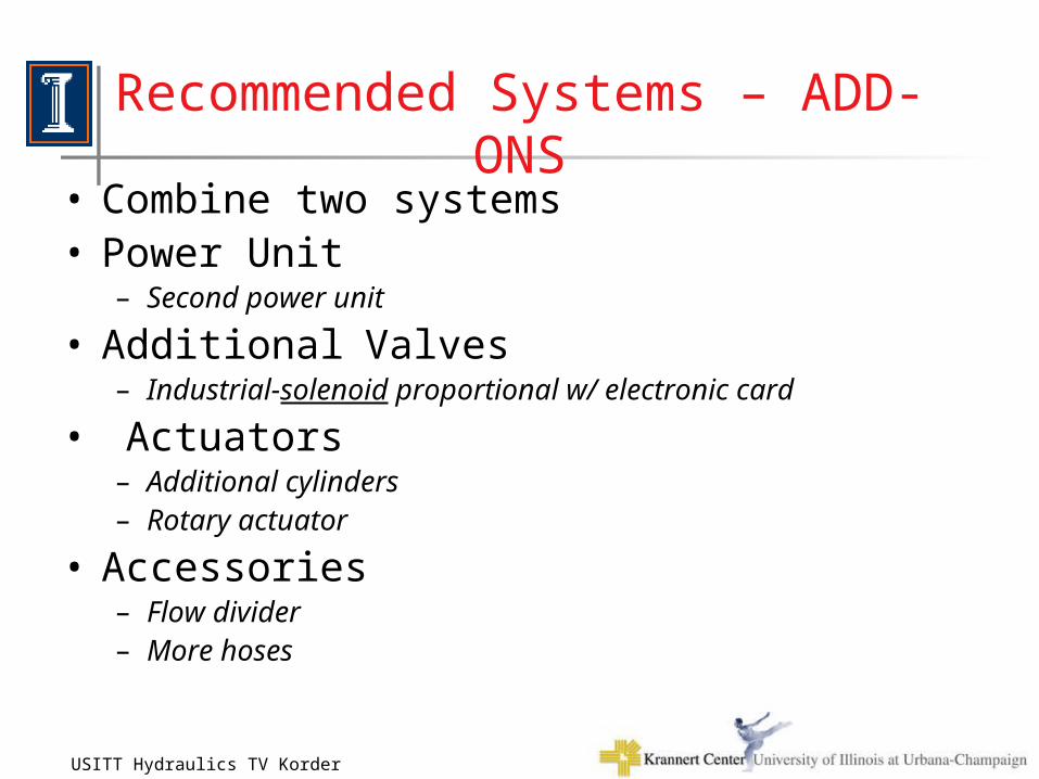
Recommended Systems – ADD-ONS• Combine two systems• Power Unit
– Second power unit
• Additional Valves– Industrial-solenoid proportional w/ electronic card
• Actuators– Additional cylinders– Rotary actuator
• Accessories– Flow divider– More hoses
16-Nov-02USITT Hydraulics TV Korder 41
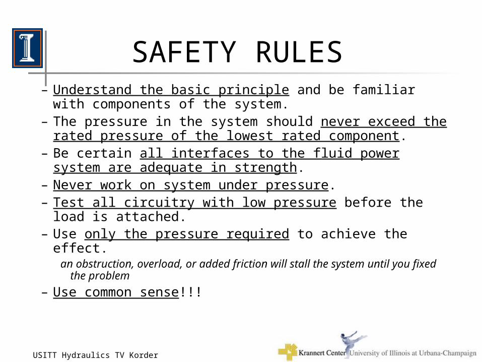
SAFETY RULES– Understand the basic principle and be familiar with
components of the system. – The pressure in the system should never exceed the rated
pressure of the lowest rated component. – Be certain all interfaces to the fluid power system are
adequate in strength.– Never work on system under pressure.– Test all circuitry with low pressure before the load is attached.– Use only the pressure required to achieve the effect.
an obstruction, overload, or added friction will stall the system until you fixed the problem
– Use common sense!!!
16-Nov-02USITT Hydraulics TV Korder 42
Jack Miller(following this slide are new slides that address these topics,
these were not included in original workshop presentation)
– Pump does not produce pressure.
– Always use a Counterbalance valve if you have a load over the cylinder.
– Be certain all interfaces to the fluid power system are adequate in strength.
–…………………………………….
16-Nov-02USITT Hydraulics TV Korder 43
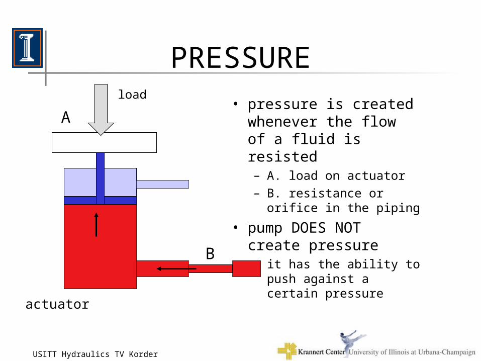
PRESSURE
• pressure is created whenever the flow of a fluid is resisted– A. load on actuator
– B. resistance or orifice in the piping
• pump DOES NOT create pressure– it has the ability to push
against a certain pressure
actuator
load
A
B
16-Nov-02USITT Hydraulics TV Korder 44
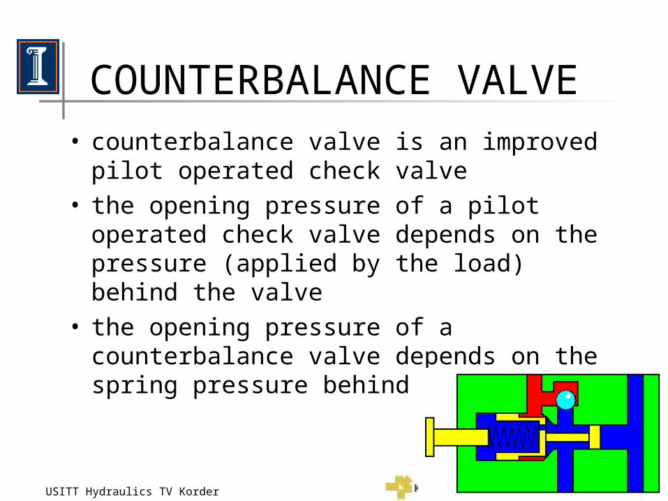
COUNTERBALANCE VALVE• counterbalance valve is an improved pilot
operated check valve• the opening pressure of a pilot operated check
valve depends on the pressure (applied by the load) behind the valve
• the opening pressure of a counterbalance valve depends on the spring pressure behind the valve.
16-Nov-02USITT Hydraulics TV Korder 45
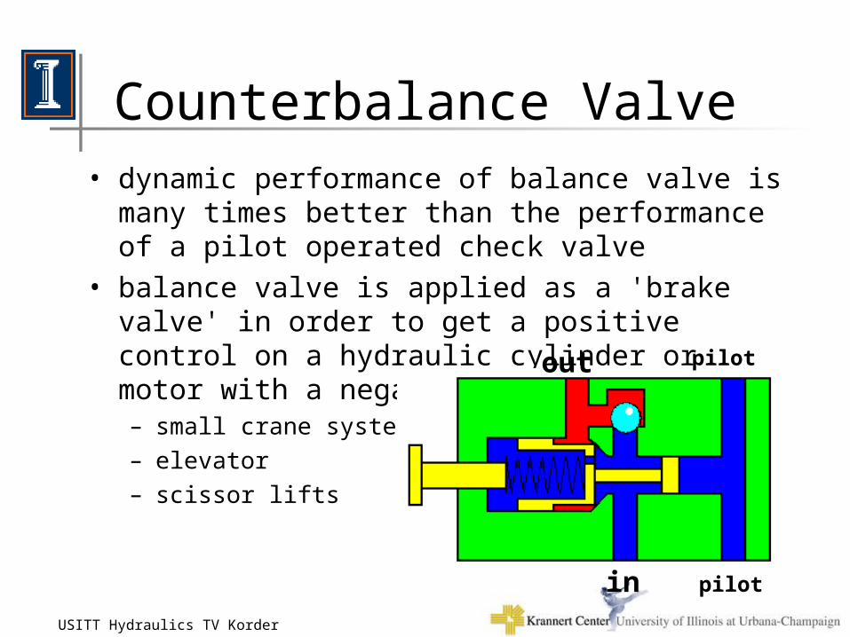
Counterbalance Valve• dynamic performance of balance valve is many times
better than the performance of a pilot operated check valve
• balance valve is applied as a 'brake valve' in order to get a positive control on a hydraulic cylinder or motor with a negative load– small crane systems
– elevator
– scissor lifts
in
out pilot
pilot
16-Nov-02USITT Hydraulics TV Korder 46
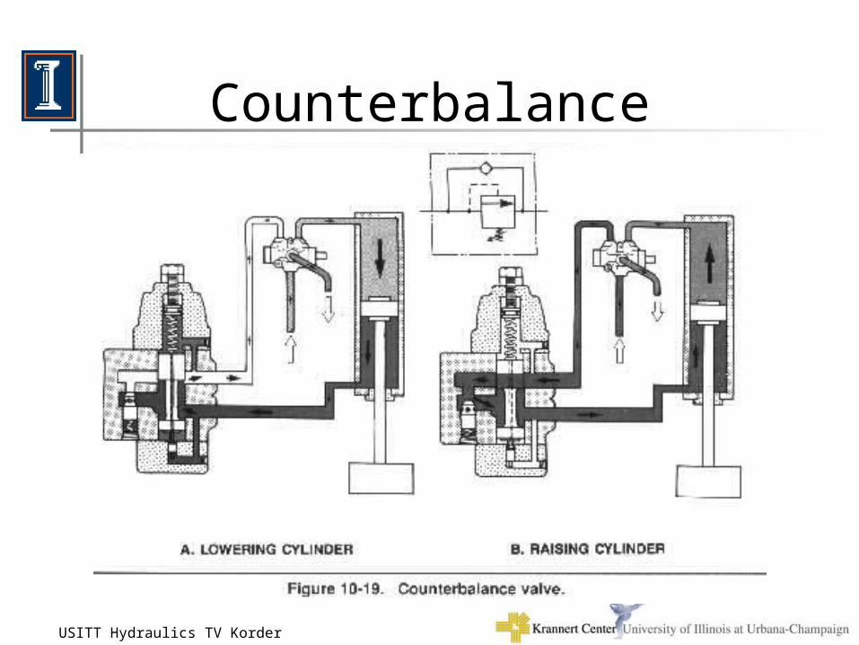
Counterbalance
16-Nov-02USITT Hydraulics TV Korder 47
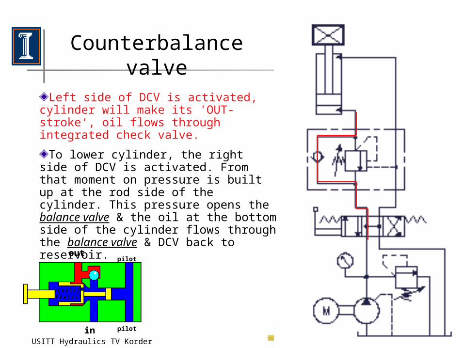
Counterbalance valve
in
outpilot
pilot
Left side of DCV is activated, cylinder will make its 'OUT-stroke‘, oil flows through integrated check valve.
To lower cylinder, the right side of DCV is activated. From that moment on pressure is built up at the rod side of the cylinder. This pressure opens the balance valve & the oil at the bottom side of the cylinder flows through the balance valve & DCV back to reservoir.
16-Nov-02USITT Hydraulics TV Korder 48
Counterbalance valve
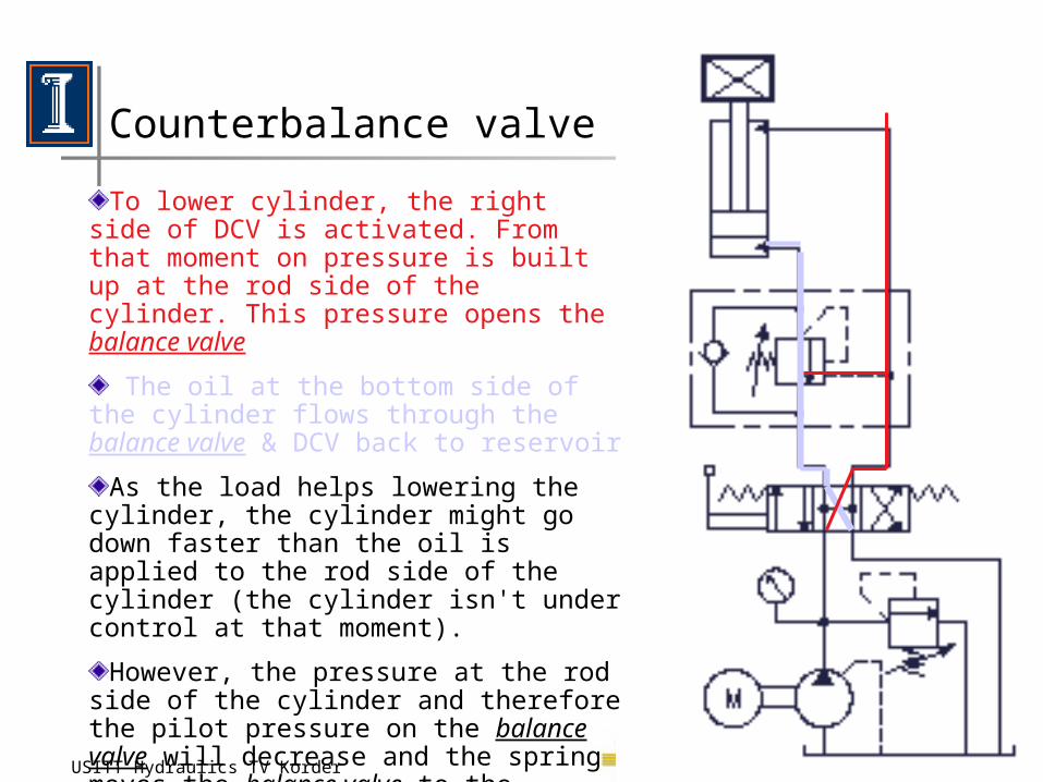
To lower cylinder, the right side of DCV is activated. From that moment on pressure is built up at the rod side of the cylinder. This pressure opens the balance valve
The oil at the bottom side of the cylinder flows through the balance valve & DCV back to reservoir
As the load helps lowering the cylinder, the cylinder might go down faster than the oil is applied to the rod side of the cylinder (the cylinder isn't under control at that moment).
However, the pressure at the rod side of the cylinder and therefore the pilot pressure on the balance valve will decrease and the spring moves the balance valve to the direction 'close' as long as it finds a new 'balance'. .
16-Nov-02USITT Hydraulics TV Korder 49
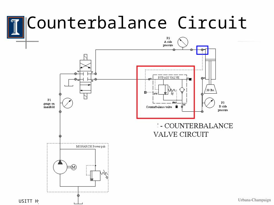
Counterbalance Circuit #1
““An Introduction to Hydraulics”An Introduction to Hydraulics”USITT- Minneapolis 2003USITT- Minneapolis 2003
Notes available athttp://www.nwmissouri.edu/%7Epimmel/usitt/tech_prod/TECH_PROD_INDEX.HTM
Contact me at: