Embed Size (px)
Citation preview

Printed in U.S.A. REVISED 03/25/2011
GF-109LN OMM-0018_0A
KC Series Gas-Fired Low NOx Boiler USER MANUAL
Applicable to Serial Numbers G-11-0030 to G-11-0694
KC Series Gas Fired Low NOx Boiler System
Natural Gas and Propane Fired, Condensing and Forced Draft Hot Water Boiler
970,000 BTU/HR Input (Natural Gas) 1,000,000 BTU/HR Input (Propane)
Patent No. 4,852,524
Telephone Support Direct to AERCO Technical Support (8am to 5 pm EST, Monday - Friday):
1-800-526-0288
AERCO International, Inc. 100 Oritani Drive Blauvelt, NY 10913
www.aerco.com
© AERCO International, Inc., 2010
The information contained in this operation and maintenance manual is subject to change without notice from AERCO International, Inc.
AERCO makes no warranty of any kind with respect to this material, including but not limited to implied warranties of merchantability and fitness for a particular application. AERCO International is not liable for errors appearing in this manual. Nor for incidental or consequential damages occurring in connection with the furnishing, performance, or use of this material.
CONTENTS
i
GF-109LN - THE AERCO KC1000 GAS FIRED LOW NOx BOILER Operating & Maintenance Instructions
FOREWARD A
SECTION 1 – SAFETY PRECAUTIONS 1-1 Para. Subject Page 1.1 Warnings & Cautions 1-1 1.2 Emergency Shutdown 1-2
Para. Subject Page 1.3 Prolonged Shutdown 1-2
SECTION 2 – INSTALLATION PROCEDURES 2-1 Para. Subject Page 2.1 Receiving the Unit 2-1 2.2 Unpacking 2-1 2.3 Installation 2-2 2.4 Gas Supply Piping 2-4 2.5 Electrical Supply 2-6 2.6 Mode of Operation and Field
Control Wiring 2-6
Para. Subject Page 2.7 I/O Box Connections 2-8 2.8 Auxiliary Relay Contacts 2-10 2.9 Flue Gas Vent Installation 2-10 2.10 Combustion Air 2-10
SECTION 3 – CONTROL PANEL OPERATING PROCEDURES 3-1 Para. Subject Page 3.1 Introduction 3-1 3.2 Control Panel Description 3-1 3.3 Control Panel Menus 3-3 3.4 Operating Menu 3-4 3.5 Setup Menu 3-4
Para. Subject Page 3.6 Configuration Menu 3-5 3.7 Tuning Menu 3-7 3.8 Start Sequence 3-8 3.9 Start/Stop Levels 3-9
SECTION 4 – INITIAL START-UP 4-1 Para. Subject Page 4.1 Initial Startup Requirements 4-1 4.2 Tools and Instrumentation for
Combustion Calibration 4-1
4.3 Natural Gas Combustion Calibration
4-2
Para. Subject Page 4.4 Propane Combustion Calibration 4-5 4.5 Unit Reassembly 4-8 4.6 Over-Temperature Limit Switch
Adjustments 4-8
Section 5 – MODE OF OPERATION 5-1 Para. Subject Page 5.1 Introduction 5-1 5.2 Indoor/Outdoor Reset Mode 5-1 5.3 Constant Setpoint Mode 5-2 5.4 Remote Setpoint Modes 5-2 5.5 Direct Drive Modes 5-3
Para. Subject Page 5.6 Boiler Management System
(BMS) 5-4
5.7 Combination Control System (CCS)
5-5
CONTENTS
ii
SECTION 6 – SAFETY DEVICE TESTING PROCEDURES 6-1 Para. Subject Page 6.1 Testing of Safety Devices 6-1 6.2 Low Gas Pressure Fault Test 6-1 6.3 High Gas Pressure Fault Test 6-1 6.4 Low Water Level Fault Test 6-2 6.5 Water Temperature Fault Test 6-2 6.6 Interlock Fault Tests 6-3 6.7 Flame Fault Test 6-3
Para. Subject Page 6.8 Air Flow Fault Test 6-4 6.9 SSOV Proof of Closure Switch 6-4 6.10 Purge Switch Open During
Purge 6-5
6.11 Ignition Switch Open During Ignition
6-5
6.12 Safety Pressure Relief Valve Test
6-6
SECTION 7 – MAINTENANCE 7-1 Para. Subject Page 7.1 Maintenance Schedule 7-1 7.2 Spark Ignitor 7-1 7.3 Flame Detector 7-2 7.4 Combustion Calibration 7-2
Para. Subject Page 7.5 Safety Device Testing 7-2 7.6 Manifold and Exhaust Tubes 7-2 7.7 Heat Exchanger Water Side
Inspection 7-4
7.8 Condensate Drain Assembly 7-5
SECTION 8 – TROUBLESHOOTING 8-1 Para. Subject Page 8.1 Introduction 8-1
Para. Subject Page
SECTION 9 – RS232 COMMUNICATION 9-1 Para. Subject Page 9.1 Introduction 9-1 9.2 RS232 Communication Setup 9-1
Para. Subject Page 9.3 Menu Processing Utilizing
RS232 Communication 9-1
9.4 Data Logging 9-2
APPENDICES App Subject Page A Boiler Menu Item Descriptions A-1 B Startup, Status and Fault
Messages B-1
C Temperature Sensor Resistance Chart
C-1
D Indoor/Outdoor Reset Ratio Charts
D-1
E Boiler Default Settings E-1
App Subject Page F Dimensional and Part Drawings F-1 G Piping Drawings G-1 H Wiring Schematics H-1 I KC1000 Control Panel Views I-1 J KC1000 Low NOx Dual-Fuel
Switch-Over Instructions J-1
K Recommended Spare Parts K-1
WARRANTIES W-1

FOREWORD
A
Foreword This system can be operated using natural gas or propane fuel. A simple spring change in the differential regulator and combustion calibration is all that is needed to switch fuels. The AERCO KC Low NOx Boiler is a true industry advance that meets the needs of today's energy and environmental concerns. Designed for application in any closed loop hydronic system, the load tracking capability relates energy input directly to fluctuating system loads through a 11:1 modulating turndown ratio. The boiler’s condensing capability offers extremely high efficiencies and makes the KC Boiler ideally suited for modern low temperature, as well as, conventional heating systems. When installed and operated on natural gas in accordance with this Instruction Manual, the KC Boiler complies with the NOx emission standards outlined in:
• South Coast Air Quality Management District (SCAQMD), Rule 1146.2
• Texas Commission on Environmental Quality (TCEQ), Title 30, Chapter 117, Rule117.465.
The KC Boiler can be used in singular or modular arrangements for inherent standby with minimum space requirements. Venting capabilities offer maximum flexibility and allow installation without normal restrictions. The advanced electronics of each KC Boiler control system offer selectable modes of operation and interface capabilities. After prolonged shutdown, it is recommended that the startup procedures in Section 4 and the safety device test procedures in Section 6 of this manual be performed, to verify system operating parameters. If there is an emergency, turn off the electrical power supply to the KC Boiler or close the manual gas valve located before the unit. The installer is to identify the emergency shut-off device. FOR SERVICE OR PARTS, contact your local sales representative or AERCO INTERNATIONAL. NAME: ORGANIZATION:
ADDRESS: TELEPHONE: INSTALLATION DATE: _____________________________________________

SAFETY PRECAUTIONS
1-1
SECTION 1 -- SAFETY PRECAUTIONS
1.1 WARNINGS & CAUTIONS Installers and operating personnel MUST, at all times, observe all safety regulations. The following warnings and cautions are general and must be given the same attention as specific precautions included in these instructions. In addition to all the requirements included in this AERCO Instruction Manual, the installation of units MUST conform with local building codes, or, in the absence of local codes, ANSI Z223.1 (National Fuel Gas Code Publication No. NFPA-54) for gas-fired boilers and ANSI/NFPASB for LP gas-fired boilers. Where applicable, the equipment shall be installed in accordance with the current Installation Code for Gas Burning Appliances and Equipment, CGA B149, and applicable Provincial regulations for the class; which should be carefully followed in all cases. Authorities having jurisdiction should be consulted before installations are made.
See pages 1-2 and 1-3 for important information regarding installation of units within the Commonwealth of Massachusetts.
IMPORTANT This Instruction Manual is an integral part of the product and must be maintained in legible condition. It must be given to the user by the installer and kept in a safe place for future reference.
WARNINGS! MUST BE OBSERVED TO PREVENT SERIOUS INJURY.
WARNING! BEFORE ATTEMPTING TO PERFORM ANY MAINTENANCE ON THE UNIT, SHUT OFF ALL GAS AND ELECTRICAL INPUTS TO THE UNIT.
WARNING DO NOT USE MATCHES, CANDLES, FLAMES, OR OTHER SOURCES OF IGNITION TO CHECK FOR GAS LEAKS.
WARNING! THE EXHAUST VENT PIPE OF THE UNIT OPERATES UNDER A POSI-TIVE PRESSURE AND THERE-FORE MUST BE COMPLETELY SEALED TO PREVENT LEAKAGE OF COMBUSTION PRODUCTS INTO LIVING SPACES.
WARNING! FLUIDS UNDER PRESSURE MAY CAUSE INJURY TO PERSONNEL OR DAMAGE TO EQUIPMENT WHEN RELEASED. BE SURE TO SHUT OFF ALL INCOMING AND OUTGOING WATER SHUTOFF VALVES. CAREFULLY DECREASE ALL TRAPPED PRESSURES TO ZERO BEFORE PERFORMING MAINTENANCE.
WARNING! ELECTRICAL VOLTAGES OF 120 VAC ARE USED IN THIS EQUIP-MENT. THEREFORE THE COVER ON THE UNIT’S POWER BOX (LOCATED ON THE FRONT RIGHT SIDE OF THE UNIT UNDER THE HOOD AND SHEET METAL SIDE PANEL) MUST BE INSTALLED AT ALL TIMES, EXCEPT DURING MAINTENANCE AND SERVICING.
CAUTIONS! Must be observed to prevent equip-ment damage or loss of operating effectiveness.
CAUTION! Many soaps used for gas pipe leak testing are corrosive to metals. The piping must be rinsed thoroughly with clean water after leak checks have been completed.
CAUTION! DO NOT use this boiler if any part has been under water. Call a qualified service technician to inspect and replace any part that has been under water.
SAFETY PRECAUTIONS
1-2
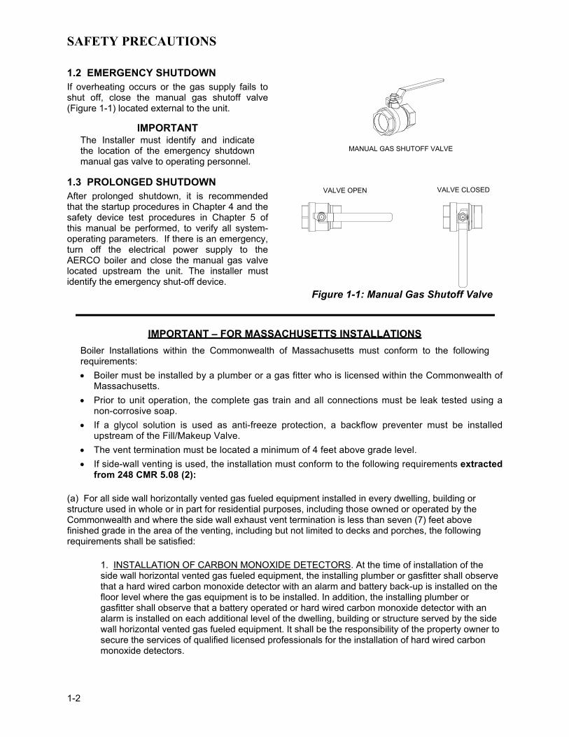
1.2 EMERGENCY SHUTDOWN If overheating occurs or the gas supply fails to shut off, close the manual gas shutoff valve (Figure 1-1) located external to the unit.
IMPORTANT The Installer must identify and indicate the location of the emergency shutdown manual gas valve to operating personnel.
1.3 PROLONGED SHUTDOWN After prolonged shutdown, it is recommended that the startup procedures in Chapter 4 and the safety device test procedures in Chapter 5 of this manual be performed, to verify all system-operating parameters. If there is an emergency, turn off the electrical power supply to the AERCO boiler and close the manual gas valve located upstream the unit. The installer must identify the emergency shut-off device.
MANUAL GAS SHUTOFF VALVE
VALVE OPEN VALVE CLOSED
Figure 1-1: Manual Gas Shutoff Valve
IMPORTANT – FOR MASSACHUSETTS INSTALLATIONS Boiler Installations within the Commonwealth of Massachusetts must conform to the following requirements: • Boiler must be installed by a plumber or a gas fitter who is licensed within the Commonwealth of
Massachusetts. • Prior to unit operation, the complete gas train and all connections must be leak tested using a
non-corrosive soap. • If a glycol solution is used as anti-freeze protection, a backflow preventer must be installed
upstream of the Fill/Makeup Valve. • The vent termination must be located a minimum of 4 feet above grade level. • If side-wall venting is used, the installation must conform to the following requirements extracted
from 248 CMR 5.08 (2):
(a) For all side wall horizontally vented gas fueled equipment installed in every dwelling, building or structure used in whole or in part for residential purposes, including those owned or operated by the Commonwealth and where the side wall exhaust vent termination is less than seven (7) feet above finished grade in the area of the venting, including but not limited to decks and porches, the following requirements shall be satisfied:
1. INSTALLATION OF CARBON MONOXIDE DETECTORS. At the time of installation of the side wall horizontal vented gas fueled equipment, the installing plumber or gasfitter shall observe that a hard wired carbon monoxide detector with an alarm and battery back-up is installed on the floor level where the gas equipment is to be installed. In addition, the installing plumber or gasfitter shall observe that a battery operated or hard wired carbon monoxide detector with an alarm is installed on each additional level of the dwelling, building or structure served by the side wall horizontal vented gas fueled equipment. It shall be the responsibility of the property owner to secure the services of qualified licensed professionals for the installation of hard wired carbon monoxide detectors.

SAFETY PRECAUTIONS
1-3
Extracted Information From 248 CMR 5.08 (2) – Continued
a. In the event that the side wall horizontally vented gas fueled equipment is installed in a crawl space or an attic, the hard wired carbon monoxide detector with alarm and battery back-up may be installed on the next adjacent floor level.
b. In the event that the requirements of this subdivision can not be met at the time of completion of installation, the owner shall have a period of thirty (30) days to comply with the above requirements; provided, however, that during said thirty (30) day period, a battery operated carbon monoxide detector with an alarm shall be installed.
2. APPROVED CARBON MONOXIDE DETECTORS. Each carbon monoxide detector as required in accordance with the above provisions shall comply with NFPA 720 and be ANSI/UL 2034 listed and IAS certified.
3. SIGNAGE. A metal or plastic identification plate shall be permanently mounted to the exterior of the building at a minimum height of eight (8) feet above grade directly in line with the exhaust vent terminal for the horizontally vented gas fueled heating appliance or equipment. The sign shall read, in print size no less than one-half (1/2) inch in size, "GAS VENT DIRECTLY BELOW. KEEP CLEAR OF ALL OBSTRUCTIONS".
4. INSPECTION. The state or local gas inspector of the side wall horizontally vented gas fueled equipment shall not approve the installation unless, upon inspection, the inspector observes carbon monoxide detectors and signage installed in accordance with the provisions of 248 CMR 5.08(2)(a)1 through 4.
(b) EXEMPTIONS: The following equipment is exempt from 248 CMR 5.08(2)(a)1 through 4:
1. The equipment listed in Chapter 10 entitled "Equipment Not Required To Be Vented" in the most current edition of NFPA 54 as adopted by the Board; and
2. Product Approved side wall horizontally vented gas fueled equipment installed in a room or structure separate from the dwelling, building or structure used in whole or in part for residential purposes.
(c) MANUFACTURER REQUIREMENTS - GAS EQUIPMENT VENTING SYSTEM PROVIDED. When the manufacturer of Product Approved side wall horizontally vented gas equipment provides a venting system design or venting system components with the equipment, the instructions provided by the manufacturer for installation of the equipment and the venting system shall include:
1. Detailed instructions for the installation of the venting system design or the venting system components; and
2. A complete parts list for the venting system design or venting system.
(d) MANUFACTURER REQUIREMENTS - GAS EQUIPMENT VENTING SYSTEM NOT PROVIDED. When the manufacturer of a Product Approved side wall horizontally vented gas fueled equipment does not provide the parts for venting the flue gases, but identifies "special venting systems", the following requirements shall be satisfied by the manufacturer:
1. The referenced "special venting system" instructions shall be included with the appliance or equipment installation instructions; and

2. The "special venting systems" shall be Product Approved by the Board, and the instructions for that system shall include a parts list and detailed installation instructions.
(e) A copy of all installation instructions for all Product Approved side wall horizontally vented gas fueled equipment, all venting instructions, all parts lists for venting instructions, and/or all venting design instructions shall remain with the appliance or equipment at the completion of the installation. _______________________________ [End of Extracted Information From 248 CMR 5.08 (2)]
INSTALLATION
2-1
SECTION 2 - INSTALLATION PROCEDURES 2.1. RECEIVING THE UNIT Each KC1000 Boiler is shipped as a single crated unit. The crated shipping weight of the unit is approximately 1500 pounds, and must be moved with the proper rigging equipment for safety and to avoid damages. The unit should be completely inspected for shipping damage and completeness at the time of receipt from the carrier and before the bill of lading is signed. Each unit has Tip-N-Tell indicator on the outside of the crate that indicates if the unit has been turned on its side. If the Tip-N-Tell indicator is tripped, do not sign for the shipment. Request a freight claim and inspection by a claims adjuster before proceeding or refuse delivery of the equipment. 2.2. UNPACKING Carefully unpack the unit. Take care not to damage the unit jacket when cutting away packaging materials. An inspection of the unit should be made to determine if damage during shipment occurred that was not indicated by the Tip-N-Tell. The freight carrier should be notified immediately if any damage is detected. The following accessories come standard with each
unit and are packed separately within the unit’s packing container
• Spare Spark Ignitor • Spare Flame Detector • Manual 1-1/4" Gas Shutoff Valve • Drain Valve Assembly • ASME Pressure Relief Valve • Differential Regulator Spring:
P/N 122548 (Propane) or P/N 124803 (Natural Gas)
• Ignitor Removal Tool (One per Site) • Temperature/Pressure Gauge and
Fittings • 2 Lifting Lugs • Stainless Steel Condensate Cup • Shell Cap • Wing Nut for Shell Cap
Optional accessories are also separately packed within the unit’s packing container. Standard and optional accessories shipped with the unit should be identified and put in a safe place until installation or use.
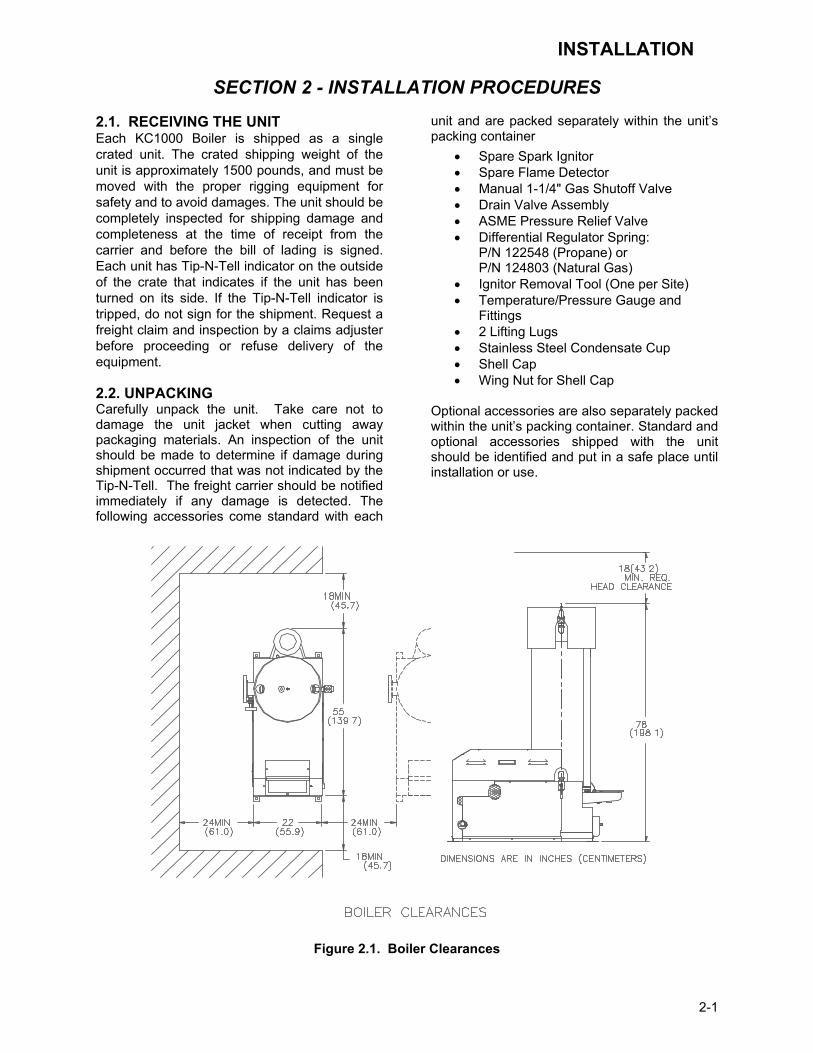
Figure 2.1. Boiler Clearances

INSTALLATION
2-2
2.3 INSTALLATION The unit must be installed with the prescribed clearances for service as shown in Figure 2.1. The minimum clearance dimensions, required by AERCO, are listed below. Local building codes may require additional clearance and take precedence Minimum clearances required: Sides 24" Front 18" Rear 18" Top 18" All gas piping, water piping, and electrical conduit or cable must be arranged so that they do not interfere with the removal of any cover, or inhibit service or maintenance of the unit.
WARNING! KEEP UNIT AREA CLEAR AND FREE FROM COMBUSTIBLE MATERIALS AND FLAMMABLE VAPORS AND LIQUIDS. MASSACHUSETTS INSTALLATIONS
For boiler installations within the Commonwealth of Massachusetts, the boiler must be installed by a plumber or gas fitter who is licensed within the Commonwealth. In addition, the boiler installation must comply with all requirements specified in Section 1 (Safety Precautions), pages 1-2 and 1-3. 2.3.1. SETTING THE UNIT Remove the unit from the wooden skid and place in position using a block and tackle or hoist attached to the lifting lugs, (see Fig. 2.2). USE ONLY THE LIFTING LUGS TO MOVE THE UNIT. The KC-1000 is U/L approved for installation on combustible flooring. A 4 to 6 inch high house-keeping concrete pad is recommended and allows for sufficient drainage of the condensate. It is suggested that units be secured using the holes provided in the frame base. Piping must not be used to secure the unit in place. See drawing AP-A-816 in Appendix F for the base frame dimensions. In multiple unit installations, it is important to plan the position of each unit. Sufficient space for piping connections and future maintenance requirements must be given. All piping must include ample provision for expansion.
If installing a Combination Control (CCP) system, it is important to identify and place the Combination Mode units in the proper physical location.
LIFTING LUGS
Figure 2.2
Lifting Lug Location
2.3.2 SUPPLY AND RETURN PIPING The locations of the 4" flanged system supply, and return piping connections, to the unit are shown in figure 2.3. The return connection is located on the left side near the base of the unit’s shell. The supply connection is located on the left side near the top of the unit’s shell. Whether installing single or multiple units, install the piping and accessories as shown in the appropriate piping diagram located in Appendix G. For applications other than standard space heating, consult the AERCO Boiler Application Guide, GF-1070, or AERCO for the appropriate piping schematics. The minimum flow rate through the unit is 25 GPM and the maximum flow rate is 150 GPM. Each unit is fitted with 4" flanges for high flow application and the system velocity at the unit return should not exceed 5 feet per second. Each unit must have individual valves on the supply, and return, for maintenance. In multiple unit installations, the flow through each unit must be balanced. Every boiler plant must have a source of make-up water to it. As with any closed loop hydronic system, air elimination and expansion equip-ment must be provided as part of the overall installation. All piping MUST include ample provision for expansion.

INSTALLATION
2-3
BOILERSUPPLY
BOILERRETURN
Figure 2.3
Supply and Return Location
NOTE:
The maximum working pressure for installations within the Province of Alberta is 87 psig. Therefore a pressure relief valve with a setting of 75 psig (or lower) should be installed for these installations. See Drawing AP-A-863 in Appendix F. 2.3.3 PRESSURE RELIEF AND DRAIN VALVE INSTALLATION An ASME rated Relief Valve is supplied with each unit. The supplied pressure relief valve setpoint will be 30, 50, 75, 100, or 150 psig as ordered from the factory. Install the pressure relief valve in the tapping provided opposite the system supply connection, (see figure 2.4). The pressure relief valve should be piped in the vertical position using the fittings supplied. A suitable pipe compound should be used on the threaded connections, and excess should be wiped off to avoid getting any into the valve body. The discharge from the relief valve should be piped to within 12 inches of the floor to prevent injury in the event of a discharge. The relief piping must be full size without reduction. No valves, restrictions, or other blockages should be allowed in the discharge line. In multiple unit installations the relief valve discharge lines must not be manifolded, (connected), together. Each must be individually
run to a suitable discharge location. The drain valve provided should be installed on the right hand side of the unit towards the bottom of the shell. The valve should be pointed in the down position, (see Fig. 2.4). 2.3.4 TEMPERATURE/PRESSURE INDICATOR The unit is supplied with one of two styles of Temperature/Pressure Indicators that must be installed in the tapping on the supply flange of the unit (see Figs. 2.5a and 2.5b). A suitable pipe compound should be used sparingly to the threaded connection.
Figure 2.4
Relief and Drain Valve Location
SHELLCAP
PARTIAL TOP VIEW OF BOILER
FOR INSTALLATION OF PRESS./TEMP. GAUGE
PART NO. 122994-1 (PRESS. RANGE 0 – 75 PSI)
SYSTEMSUPPLY
1/2" x 1 /4" REDUCING BUSHING
PRESS./TEMP. GAUGE
Figure 2.5a Pressure /Temperature Gauge Installation

INSTALLATION
2-4
SHELLCAP
PARTIAL TOP VIEW OF BOILER
FOR INSTALLATION OF PRESS./TEMP. GAUGEPART NO. 122994-2 (PRESS. RANGE 0 – 200 PSI)PART NO. 122994-3 (PRESS. RANGE 0 – 300 PSI)
SYSTEMSUPPLY
1/2" NIPPLE
1/2" UNION
PRESS./TEMP. GAUGE
Figure 2.5b Pressure/Temperature Gauge Installation
2.3.5 CONDENSATE PIPING The KC Boiler is designed to condense. There-fore, the installation site must include suitable provisions for condensate drainage or collection. A stainless steel condensate cup is separately packed within the unit’s shipping container. To install the condensate cup, pro-ceed as follows:
1. Remove the left side panel and only the left half of the rear cover to provide access to the exhaust manifold and burner (Figure 2.6).
2. Insert the 1-3/4 inch manifold drain hose into the condensate cup. Allow the cup to rest on the floor directly beneath the manifold drain hole (Figure 2.6).
3. Attach a length of 3/4 inch I.D. polypropylene tubing to the condensate cup drain tube and route it to a floor drain. If a floor drain is not available, a condensate pump can be used to remove the condensate to drain. The condensate drain line must be removable for routine main-tenance. Therefore, DO NOT hard-pipe.
4. Replace the rear cover and side panel on the unit.
TEMPERATURE SENSOR
EXHAUSTMANIFOLD
CONDENSATEDRAIN
BURNER
HOSE CLAMP
1-3/4" O.D. x 8-1 /2 “ LG.SILICONE HOSE
5/8" O.D. TUBE CONN.
CONDENSATE CUPPLACED ON FLOOR
Figure 2.6
Condensate Drain System Location
2.4. GAS SUPPLY PIPING The AERCO Gas Fired Equipment Gas Compo-nents and Supply Design Guide (GF-1030) must be consulted before any gas piping is designed or started.
WARNING! DO NOT USE MATCHES, CANDLES, FLAMES OR OTHER SOURCES OF IGNITION TO CHECK FOR GAS LEAKS.
CAUTION! Soaps used for gas pipe leak testing can be corrosive to metals. Piping must be rinsed thoroughly with clean water after leak checks have been completed.
NOTE: All gas piping must be arranged so that it does not interfere with removal of any cover, inhibit service or maintenance, or prevent access between the unit and walls, or another unit.

INSTALLATION
2-5
The location of the 1-1/4" inlet gas connection is on the right side of the unit as shown in Figure 2.7. All pipe should be de-burred and internally cleared of any scale or iron chips before installation. No flexible connectors or non-approved gas fittings should be installed. Piping should be supported from floor or walls only and must not be secured to the unit. A suitable piping compound, approved for use with gas, should be used sparingly. Any excess must be wiped off to prevent clogging of components. To avoid damage to the unit, when pressure testing gas piping, isolate the unit from the supply gas piping. At no time should there be more than 14” W.C. the unit. Bubble test all external piping thoroughly for leaks using a soap and water solution or suitable equivalent. The gas piping must meet all applicable codes.
Figure 2.7
Gas Supply Regulator and Manual Shut -Off Valve Location
2.4.1 GAS SUPPLY PRESSURE REGULATOR A mandatory external, in-line, supply gas regu-lator (supplied by others) must be installed upstream of each KC1000 and positioned as shown in Figure 2.7. Union connections should be placed in the proper locations to allow maintenance of the regulator if required. The regulator must be capable of providing the required gas pressures for natural gas and propane units as described in the paragraphs which follow.
Natural Gas: The maximum static inlet pressure to the unit must be no more than 14” W.C. Minimum gas pressure is 8.8” W.C. for FM gas trains and 9.2” W.C. for IRI gas trains when the unit is firing at maximum input. Gas pressure should not exceed 11.5” W.C. at any time when firing. Proper sizing of the gas supply regulator in delivering the correct gas flow and outlet pressure is mandatory. The gas supply pressure regulator must maintain the gas pressure at a regulated 8.8” W.C. minimum for FM gas trains and 9.2” W.C. for IRI gas trains at maximum BTU input (970,000 BTU/HR) for natural gas installations. The supply gas regulator must be of sufficient capacity volume, (1000 cfh), for the unit and should have no more than 1" droop from minimum to full fire. Propane: The maximum static inlet pressure to the unit must be no more than 14” W.C. Minimum gas pressure is 7.7” W.C. for FM gas trains and 8.1” W.C. for IRI gas trains when the unit is firing at maximum input. Gas pressure should not exceed 11.5” W.C. at any time when firing. Proper sizing of the gas supply regulator in delivering the correct gas flow and outlet pressure is mandatory. The gas supply pressure regulator must maintain the gas pressure at a regulated 7.7” W.C. minimum for FM gas trains and 8.1” W.C. for IRI gas trains at maximum BTU input (1,000,000 BTU/HR) for propane installations. The supply gas regulator must be of sufficient capacity volume, (400 cfh), for the unit and should have no more than 1" droop from minimum to full fire.
The supply gas regulator must be rated to handle the maximum incoming supply gas pressure. When the gas supply pressure will not exceed 14” W.C. a non-lock up or flow through style regulator may be used. When supply gas pressure will exceed 14” W.C., a lock up style regulator must be used. The gas supply regulator must be propery vented to outdoors. Consult the local gas utility for exact require-ments concerning venting of supply gas regulators.
CAUTION! A lockup style regulator must be used when gas supply pressure exceeds 14” W.C.

INSTALLATION
2-6
2.4.2 MANUAL GAS SHUTOFF VALVE A 1-1/4” manual gas shut-off valve is furnished with each unit. The valve should be positioned as shown in Figure 2.7. The manual gas shut-of valve must be installed upstream of the supply regulator in a readily accessible location. 2.4.3 IRI GAS TRAIN KIT The IRI gas train is an optional gas train required in some areas by code or for insurance purposes. The IRI gas train is factory pre-piped and wired. (See Appendix F, Drawing No. SD-A-660). 2.5 ELECTRICAL SUPPLY The AERCO Gas Fired Equipment Electrical Power Wiring Guide, (GF-1060), must be consulted in addition to the following material before wiring to the unit is started. AC power connection to the unit are made at the Power Box.This box is located on the front right side of the unit as shown in Figure 2.8. Conduit should be run from the knockouts in the side of the box in such a manner that it does not interfere with the removal of any sheet metal covers. A flexible electrical connection may be utilized to allow the covers to be easily removed.
POWER BOX
BLOWERSSOVACTUATOR
FRAME
Figure 2.8
AC Power Box Location
NOTE:
All electrical conduit and hardware should be installed so that it does not interfere with the removal of any cover, inhibit service or maintenance, or prevent access between the unit and walls or another unit. 2.5.1 ELECTRICAL REQUIREMENTS Electrical requirements for each unit are 120 VAC, Single Phase, 60 Hz, 20 Amps from a dedicated electrical circuit. No other devices should be on the same electrical circuit as the KC1000 unit. A means for disconnecting AC power from the unit (such as a service switch) must be installed near the unit for normal opera-tion and maintenance. All electrical connections should be made in accordance with the National Electrical Code and/or with any applicable local codes. The AC power wiring diagram is shown in Figure 2.9.
USE COPPER CONDUCTORS ONLY FOR FIELD WIRING
60 HZ
DISCONNECT POWER BEFORE SERVICINGDANGER: HIGH VOLTAGE
20 AMP
120 VAC,
NEUTRAL
GROUND
LINE
POWER BOXAERCO INTERNATIONAL INC.
INPUT POWER
Figure 2.9 AC Power Wiring Diagram
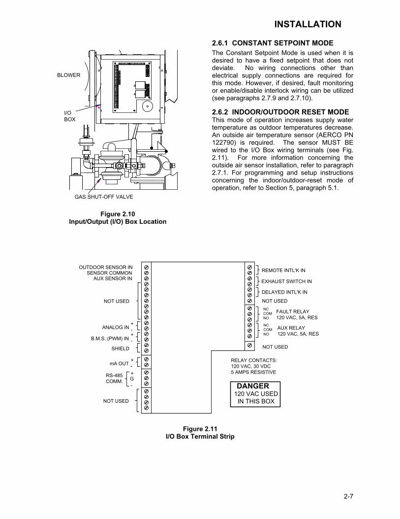
2.6 MODE OF OPERATION and FIELD CONTROL WIRING The KC Boiler is available in several different modes of operation. While each unit is factory configured and wired for the mode specified on the equipment order, some field wiring may be required to complete the installation. This wiring is typically routed to the Input/Output (I/O) Box located on the left side of the unit beneath the removable side panel (see Fig. 2.10). Field wiring for each particular mode of operation is described in the following paragraphs. For additional information concerning modes of operations, refer to Section 5.
INSTALLATION
2-7
I/OBOX
GAS SHUT-OFF VALVE
BLOWER
Figure 2.10
Input/Output (I/O) Box Location
2.6.1 CONSTANT SETPOINT MODE The Constant Setpoint Mode is used when it is desired to have a fixed setpoint that does not deviate. No wiring connections other than electrical supply connections are required for this mode. However, if desired, fault monitoring or enable/disable interlock wiring can be utilized (see paragraphs 2.7.9 and 2.7.10). 2.6.2 INDOOR/OUTDOOR RESET MODE This mode of operation increases supply water temperature as outdoor temperatures decrease. An outside air temperature sensor (AERCO PN 122790) is required. The sensor MUST BE wired to the I/O Box wiring terminals (see Fig. 2.11). For more information concerning the outside air sensor installation, refer to paragraph 2.7.1. For programming and setup instructions concerning the indoor/outdoor-reset mode of operation, refer to Section 5, paragraph 5.1.
mA OUT
RS-485COMM.
+
-
+-
ANALOG IN
SENSOR COMMONOUTDOOR SENSOR IN REMOTE INTL'K IN
B.M.S. (PWM) IN
SHIELD
+-
+-
AUX SENSOR IN
NOT USED
EXHAUST SWITCH IN
DELAYED INTL'K IN
FAULT RELAY120 VAC, 5A, RES
AUX RELAY120 VAC, 5A, RES
G
RELAY CONTACTS:120 VAC, 30 VDC5 AMPS RESISTIVE
DANGER120 VAC USED
IN THIS BOX
NOT USED NOT USEDNCCOMNO
NCCOMNO
NOT USED
Figure 2.11 I/O Box Terminal Strip

INSTALLATION
2-8
2.6.3 BOILER MANAGEMENT SYSTEM (BMS) MODE
NOTE BMS Model 168 can utilize either pulse width modulation (PWM) or RS485 Modbus signaling to the Boiler. BMS II Model 5R5-384 can utilize only RS485 signaling to the Boiler.
When using an AERCO Boiler Management System (BMS), the field wiring is connected between the BMS Panel and each Boiler’s I/O Box terminal strip (Figure 2-11). Twisted shielded pair wire from 18 to 22 AWG must be utilized for the connections. The BMS Mode can utilize either pulse width modulation (PWM) signaling, or RS485 Modbus signaling. For PWM signaling, connections are made from the AERCO Boiler Management System to the B.M.S. (PWM) IN terminals on the I/O Box terminal strip. For RS485 Modbus signaling, connections are made from the BMS to the RS485 COMM terminals on the I/O Box terminal strip. Polarity must be maintained and the shield must be connected only at the AERCO BMS. The boiler end of the shield must be left floating. For additional instructions, refer to Chapter 5, paragraph 5.6 in this manual. Also, refer to GF-108M (BMS Model 168) and GF-124 (BMS II Model 5R5-184), BMS -Operations Guides.
2.6.4 REMOTE SETPOINT and DIRECT DRIVE MODES The KC1000 Boiler can accept several types of signal formats from an Energy Management System or other source to control either the setpoint (Remote Setpoint Mode) or air/fuel valve position (Direct Drive Mode) of the Boiler. These formats are: 4 to 20 mA/1 to 5 Vdc 0 to 20 mA/0 to 5 Vdc PWM – (Pulse Width Modulated signal. See paragraph 2.7.4) Network – (RS485 Modbus. See para. 2.7.7) While it is possible to control one or more boilers using one of the above modes of operation, it may not be the method best suited for the application. Prior to selecting one of the above modes of operation, it is recommended that you consult with your local AERCO representative or the factory for the mode of operation that will work best with your application. For more
information on wiring the 4 to 20 mA / 1to 5VDC or the 0 to 20 mA / 0 to 5 VDC, see paragraph 2.7.3.
2.6.5 COMBINATION MODE NOTE
Only BMS Model 168 can be utilized for the Combination Mode, not the BMS II (Model 5R5-384).
With a Combination Mode unit, field wiring is between the unit’s I/O Box, the CCP (Combination Control Panel), and the BMS Model 168 (Boiler Management System). The wiring must be done using a shielded twisted pair of 22 AWG wire. Polarity must be maintained between the unit, the CCP, and the BMS. For further instructions and wiring diagrams, refer to the GF-108 Boiler Management System Operations Guide and the CCP-1 data sheet.
2.7 I/O BOX CONNECTIONS The types of input and output/signals and devices to be connected to the I/O Box terminals shown in Figure 2.11 are described in the following paragraphs.
CAUTION! DO NOT make any connections to the I/O Box terminals labeled “NOT USED”. Attempting to do so may cause equipment damage.
2.7.1 OUTDOOR SENSOR IN An outdoor air temperature sensor (AERCO Part No. 122790) will be required mainly for the Indoor/Outdoor Reset mode of operation. It can also be used with another mode if it is desired to use the outdoor sensor enable/disable feature. This feature allows the boiler to be enabled or disabled based on the outdoor air temperature. The factory default for the outdoor sensor is DISABLED. To enable the sensor and or choose an enable/disable outdoor temperature, see the Configuration menu in Section 3 and Appendix A. The outdoor sensor may be wired up to 200 feet from the boiler and is connected to the OUTDOOR SENSOR IN and SENSOR COMMON terminals in the I/O box (see Figs. 2.10 and 2.11). Wire the sensor using a twisted shielded pair cable of 18-22 AWG wire. There is no polarity when terminating the wires. The

INSTALLATION
2-9
shield is to be connected only to the terminals labeled SHEILD in the I/O Box. The sensor end of the shield must be left free and ungrounded. When mounting the sensor, it must be located on the North side of the building where an average outside air temperature is expected. The sensor must be shielded form direct sunlight as well as impingement by the elements. If a shield is used, it must allow for free air circulation.
2.7.2 AUX SENSOR IN The AUX SENSOR IN terminals can be used to add an additional temperature sensor for monitoring purposes. This input is always enabled and is a view only input that can be seen in the operating menu. The sensor must be wired to the AUX SENSOR IN and SENSOR COMMON and must be similar to AERCO BALCO wire sensor P/N 12449. A resistance chart for this sensor is provided in Appendix C.
2.7.3 ANALOG IN The ANALOG IN + and – terminals are used when an external signal is used to drive the air/fuel valve position (Direct Drive Mode) or change the setpoint (Remote Setpoint Mode) of the Boiler. Either a 4 to 20 mA / 1 to 5 VDC or a 0 to 20 mA / 0 to 5 VDC signal may be used to vary the setpoint or valve position. The factory default setting is 4 to 20 mA / 1 to 5 VDC, however this may be changed to 0 to 20 mA / 0 to 5 VDC using the Configuration Menu described in Section 3. If voltage rather than current is selected as the drive signal, a DIP switch must be set on the CPU Board located inside the Control Box. Contact the AERCO factory for information on setting DIP switches. All of the supplied signals must be floating (ungrounded) signals. Connections between the source and the Boiler’s I/O Box must be made using twisted shielded pair of 18 –22 AWG wire such as Belden 9841(see Fig. 211). Polarity must be maintained and the shield must be connected only at the source end and must be left floating (not connected) at the Boiler’s I/O Box. Whether using voltage or current for the drive signal, they are linearly mapped to a 40°F to 240°F setpoint or a 0% to 100% valve position. No scaling for these signals is provided.
2.7.4 B.M.S. (PWM) IN NOTE
Only BMS Model 168 can utilize Pulse Width Modulation (PWM), not the BMS II (Model 5R5-384).
These terminals are used to connect the AERCO Boiler Management System (BMS) Model 168 to the unit. The BMS Model 168 utilizes a 12 millisecond, ON/OFF duty cycle. This duty cycle is Pulse Width Modulated (PWM) to control air/fuel valve position. A 0% valve position = a 5% ON pulse and a 100% valve position = a 95% ON pulse.
2.7.5 SHIELD The SHIELD terminals are used to terminate any shields used on sensor wires connected to the unit. Shields must only be connected to these terminals.
2.7.6 mA OUT These terminals provide a 4 to 20 mA output that can be used to monitor setpoint (40°F to 220°F), outlet temperature (30°F to 245°F), or air/fuel valve position (0% to 100% open). This function is enabled in the Configuration Menu (Section 3, Table 3.4).
2.7.7 RS-485 COMM These terminals are used for RS-485 MODBUS serial communication between the unit and an external “Master”, such as a Boiler Management System or other suitable device.
2.7.8 EXHAUST SWITCH IN These terminals permit an external exhaust switch to be connected to the exhaust manifold of the boiler. The exhaust sensor should be a normally open type switch (such as AERCO Part No. 123463) that closes (trips) at 500oF.
2.7.9 INTERLOCKS The unit offers two interlock circuits for inter-facing with Energy Management Systems and auxiliary equipment such as pumps or louvers. These interlocks are called the Remote Interlock and Delayed Interlock (Fig. 2.11). The wiring terminals for these interlocks are located inside the I/O Box on the left side of the unit. The I/O Box cover contains a wiring diagram which shows the terminal strip locations for these inter-locks which are labeled REMOTE INTL’K IN and DELAYED INTL’K IN. Both interlocks, described in the following paragraphs, are factory wired in the closed position.

INSTALLATION
2-10
NOTE:
Both the Delayed Interlock and Remote Interlock must be in the closed position to allow the unit to fire.
2.7.9.1 REMOTE INTERLOCK IN The remote interlock circuit (REMOTE INTL’K IN) is provided to remotely start (enable) and stop (disable) the Boiler if desired. The circuit is 24 VAC and comes factory pre-wired closed (jumpered).
2.7.9.2 DELAYED INTERLOCK IN The delayed interlock circuit (DELAYED INTL’K IN) is typically used in conjunction with the auxiliary relay described in paragraph 2.8. This interlock circuit is located in the purge section of the start string. It can be connected to the proving device (end switch, flow switch etc.) of an auxiliary piece of equipment started by the boiler’s auxiliary relay. The delayed interlock must be closed for the boiler to fire. If the delayed interlock is connected to a proving device that requires time to close (make), a time delay (Aux Start On Dly) that holds the start sequence of the boiler long enough for for a proving switch to make can be programmed. Should the proving switch not prove within the programmed time frame, the boiler will shut down. The Aux Start On Dly can be programmed from 0 to 120 seconds. This option is locate in the Configuration Menu (Section 3).
2.7.10 FAULT RELAY The fault relay is a single pole double throw (SPDT) relay having a normally open and normally close set of relay contacts that are rated for 5 amps at 120 VAC and 5 amps at 30 VDC. The relay energizes when any fault con-dition occurs and remains energized until the fault is cleared and the CLEAR button is depressed. The fault relay connections are shown in Figure 2.11.
2.8 AUXILIARY RELAY CONTACTS Each KC Boiler is equipped with a single pole double throw (SPDT) relay that is energized when there is a demand for heat and de-energized after the demand for heat is satisfied. The relay is provided for the control of auxiliary equipment, such as pumps and louvers, or can be used as a Boiler status indictor (firing or not firing). Its contacts are rated for 120 VAC @ 5 amps. Refer to Figure 2.11 to locate the AUX RELAY terminals for wiring connections.
2.9 FLUE GAS VENT INSTALLATION The AERCO Venting and Combustion Air Guide, GF-1050, must be consulted before any flue or inlet air venting is designed or installed. Suitable, U/L approved, positive pressure, water-tight vent materials as specified in AERCO’s GF-1050, must be used for safety and UL certification. Because the unit is capable of discharging low temperature exhaust gases, the flue must be pitched back to the unit a minimum of 1/4" per foot to avoid any condensate pooling and to allow for proper drainage. While there is a positive flue pressure during operation, the combined pressure drop of vent and combustion air systems must not exceed 140 equivalent feet of 0.81” W.C. Fittings as well as pipe lengths must be calculated as part of the equivalent length. For a natural draft installation the draft must not exceed - 0.25” W.C. These factors must be planned into the vent installation. If the maximum allowable equivalent lengths of piping are exceeded, the unit will not operate properly or reliably. For Massachusetts boiler installations, the Heatfab Division of the Selkirk Corporation provides vent systems which conform to all applicable requirements for installations within the Commonwealth of Massachusetts. Contact information for this supplier is as follows:
Selkirk Corporation Heatfab Division 130 Industrial Blvd. Turners Falls, MA 01376 Phone: 1-800-772-0739 www.heat-fab.com
2.10 COMBUSTION AIR The AERCO Venting and Combustion Air Guide, GF-1050, MUST be consulted before any flue or combustion supply air venting is designed or started. Combustion air supply is a direct requirement of ANSI 223.1, NFPA-54, and local codes. These codes should be consulted before a permanent design is determined. The combustion air must be free of chlorine, halogenated hydrocarbons, or other chemicals that can become hazardous when used in gas-fired equipment. Common sources of these compounds are swimming pools, degreasing compounds, plastic processing and refrigerants. Whenever the environment contains these types of chemicals, combustion air must be supplied from a clean area outdoors for the protection and longevity of the equipment.
INSTALLATION
2-11
The more common methods of supplying combustion air are outlined below. For more information on combustion air, consult the AERCO GF-1050, Venting and Combustion Air Guide.
2.10.1 COMBUSTION AIR FROM OUTSIDE THE BUILDING Air supplied from outside the building must be provided through two permanent openings. For each unit these two openings must have a free area of not less than one square inch for each 4000 BTUs input of the equipment or 250 square inches of free area. The free area must take into account restrictions such as louvers and bird screens. 2.10.2 COMBUSTION AIR FROM INSIDE THE BUILDING When combustion air is provided from within the building, it must be supplied through two permanent openings in an interior wall. Each opening must have a free area of not less than one square inch per 1000 BTUH of total input or 1000 square inches of free area. The free area must take into account any restrictions such as louvers.
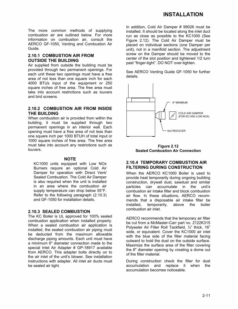
NOTE KC1000 units equipped with Low NOx Burners require an optional Cold Air Damper for operation with Direct Vent/ Sealed Combustion. The Cold Air Damper is also required when the unit is installed in an area where the combustion air supply temperature can drop below 55°F. Refer to the following paragraph (2.10.3) and GF-1050 for installation details.
2.10.3 SEALED COMBUSTION The KC Boiler is UL approved for 100% sealed combustion application when installed properly. When a sealed combustion air application is installed, the sealed combustion air piping must be deducted from the maximum allowable discharge piping amounts. Each unit must have a minimum 6" diameter connection made to the special Inlet Air Adapter # GP-18917 available from AERCO. This adapter bolts directly on to the air inlet of the unit’s blower. See installation instructions with adapter. All inlet air ducts must be sealed air tight.
In addition, Cold Air Damper # 99026 must be installed. It should be located along the inlet duct run as close as possible to the KC1000 (See Figure 2.12). The Cold Air Damper must be placed on individual sections (one Damper per unit), not in a manifold section. The adjustment screw on the Damper should be moved to the center of the slot position and tightened 1/2 turn past “finger-tight”. DO NOT over-tighten. See AERCO Venting Guide GF-1050 for further details.
6" MINIMUM
6x3 REDUCER
COLD AIR DAMPER(FOR KC1000 LOW NOX)
Figure 2.12 Sealed Combustion Air Connection
2.10.4 TEMPORARY COMBUSTION AIR FILTERING DURING CONSTRUCTION When the AERCO KC1000 Boiler is used to provide heat temporarily during ongoing building construction, drywall dust, sawdust and similar particles can accumulate in the unit’s combustion air intake filter and block combustion air flow. In these situations, AERCO recom-mends that a disposable air intake filter be installed, temporarily, above the boiler combustion air inlet.
AERCO recommends that the temporary air filter be cut from a McMaster-Carr part no. 2122K315 Polyester Air Filter Roll Tackfield, ½” thick, 16” wide, or equivalent. Cover the KC1000 air inlet with the blue side of the filter material facing outward to hold the dust on the outside surface. Maximize the surface area of the filter covering the 8" diameter opening by creating a dome out of the filter material.
During construction check the filter for dust accumulation and replace it when the accumulation becomes noticeable.


CONTROL PANEL OPERATING PROCEDURES
3-1
SECTION 3 - CONTROL PANEL OPERATING PROCEDURES
3.1. INTRODUCTION The information in this Section provides a guide to the operation of the KC1000 Boiler using the Control Panel mounted on the front of the unit. It is imperative that the initial startup of this unit be performed by factory trained personnel. Operation prior to initial startup by factory trained personnel will void the equipment warranty. In addition, the following WARNINGS and CAUTIONS must be observed at all times.
CAUTION: All initial installation procedures must be satisfied before attempting to start the unit.
WARNING: ELECTRICAL VOLTAGES IN THIS SYSTEM INCLUDE 120 AND 24 VOLTS AC. IT MUST NOT BE SERVICED OR ACCESSED BY OTHER THAN FACTORY CERTIFIED SERVICE TECHNICIANS.
WARNING:
DO NOT ATTEMPT TO DRY FIRE THE BOILER. STARTING THE UNIT WITHOUT A FULL WATER LEVEL CAN SERIOUSLY DAMAGE THE UNIT AND MAY RESULT IN PERSONNEL INJURY OR PROPERTY DAMAGE. THIS SITUATION WILL VOID ANY WARRANTY.
3.2. CONTROL PANEL DESCRIPTION The KC1000 Control Panel shown in Figure 3-1 contains all of the controls, indicators and displays necessary to operate, adjust and troubleshoot the KC1000 Boiler. These operat-ing controls, indicators and displays are listed and described in Table 3-1. Additional informa-tion on these items are provided in the individual operating procedures provided in this Section.
31 2
7
4
6
10 89
5
11
12
Figure 3-1. Control Panel Front View
CONTROL PANEL OPERATING PROCEDURES
3-2
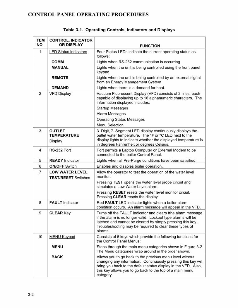
Table 3-1. Operating Controls, Indicators and Displays
ITEM NO.
CONTROL, INDICATOR OR DISPLAY
FUNCTION
1 LED Status Indicators Four Status LEDs indicate the current operating status as follows:
COMM Lights when RS-232 communication is occurring MANUAL Lights when the unit is being controlled using the front panel
keypad. REMOTE Lights when the unit is being controlled by an external signal
from an Energy Management System DEMAND Lights when there is a demand for heat. 2 VFD Display Vacuum Fluorescent Display (VFD) consists of 2 lines, each
capable of displaying up to 16 alphanumeric characters. The information displayed includes: Startup Messages Alarm Messages Operating Status Messages Menu Selection
3 OUTLET TEMPERATURE Display
3–Digit, 7–Segment LED display continuously displays the outlet water temperature. The °F or °C LED next to the display lights to indicate whether the displayed temperature is in degrees Fahrenheit or degrees Celsius.
4 RS-232 Port Port permits a Laptop Computer or External Modem to be connected to the boiler Control Panel.
5 READY Indicator Lights when all Pre-Purge conditions have been satisified. 6 ON/OFF Switch Enables and disables boiler operation. 7 LOW WATER LEVEL
TEST/RESET Switches Allow the operator to test the operation of the water level monitor. Pressing TEST opens the water level probe circuit and simulates a Low Water Level alarm. Pressing RESET resets the water level monitor circuit. Pressing CLEAR resets the display.
8 FAULT Indicator Red FAULT LED indicator lights when a boiler alarm condition occurs. An alarm message will appear in the VFD.
9 CLEAR Key Turns off the FAULT indicator and clears trhe alarm message if the alarm is no longer valid. Lockout type alarms will be latched and cannot be cleared by simply pressing this key. Troubleshooting may be required to clear these types of alarms
10 MENU Keypad Consists of 6 keys which provide the following functions for the Control Panel Menus:
MENU Steps through the main menu categories shown in Figure 3-2. The Menu categories wrap around in the order shown.
BACK Allows you to go back to the previous menu level without changing any information. Continuously pressing this key will bring you back to the default status display in the VFD. Also, this key allows you to go back to the top of a main menu category.

CONTROL PANEL OPERATING PROCEDURES
3-4
Table 3-1. Operating Controls, Indicators and Displays - Continued
ITEM NO.
CONTROL, INDICATOR OR DISPLAY
FUNCTION
10 (Cont.)
▲ (Up) Arrow When in one of the main menu categories (Figure 3-2), pressing this key will select the displayed menu category. If the CHANGE key was pressed and the menu item is flashing, pressing the ▲ arrow key will increment the selected setting.
▼ (Down) Arrow When in one of the main menu categories (Figure 3-2), pressing this key will select the displayed menu category. If the CHANGE key was pressed and the menu item is flashing, pressing the ▼ (Down) arrow key will increment the selected setting.
CHANGE Permits a setting to be changed (edited). When the
CHANGE key is pressed, the displayed menu item will begin to flash. Pressing the ▲ or ▼ arrow key when the item is flashing will increment or decrement the displayed setting.
ENTER Saves the modified menu information in memory. The display will stop flashing.
11 AUTO/MAN Switch This switch toggles the boiler between the Automatic and Manual modes of operation. When in the Manual (MAN) mode, the front panel controls are enabled and the MANUAL status LED lights.
When in the Automatic (AUTO) mode, the MANUAL status LED will be off and the front panel controls disabled.
12 VALVE POSITION Bargraph
20 segment red LED bargraph continuously shows the Air/Fuel Valve Position (% open) in 5% increments from 0 to 100%
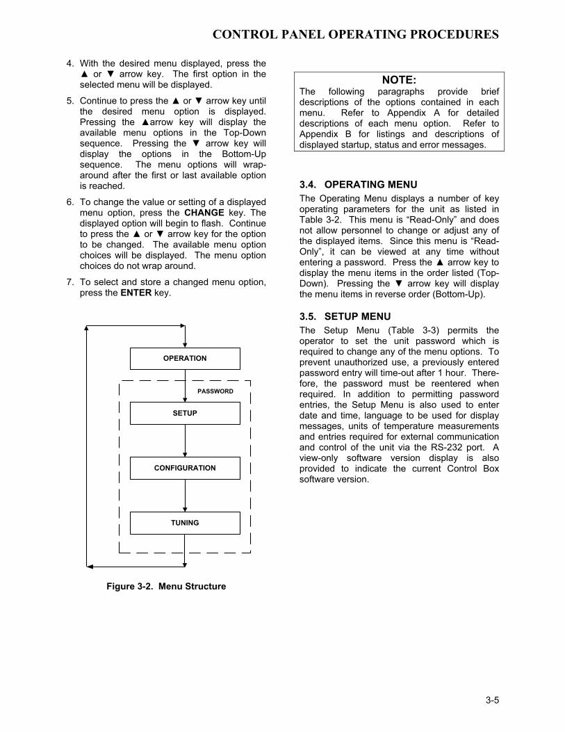
3.3. CONTROL PANEL MENUS The Control Panel incorporates an extensive menu structure which permits the operator to set up, and configure the unit. The menu structure consists of four major menu categories as shown in Figure 3-2. Each of the menus shown, contain options which permit operating parameters to be viewed or changed. The menus are protected by a password to prevent unauthorized use. Prior to entering the correct password, the options contained in the Operating, Setup, Configuration and Tuning Menu categories can be viewed. However, with the exception of Internal Setpoint Temperature (Configuration Menu), none of the viewable menu options can be changed. Once the valid password (159) is entered, the options listed in the Setup, Configuration and Tuning menus can be viewed and changed, if desired.
3.3.1. Menu Processing Procedure Accessing each menu and option is accomplished using the Menu Keys shown in Figure 3-1. Therefore, it is imperative that you be thoroughly familiar with the following basic steps before attempting to perform specific menu procedures.
1. The Control Panel will normally be in the Operating Menu and the VFD will display the current unit status. Pressing the ▲ or ▼ arrow key will display the other available data items in the Operating Menu.
2. Press the MENU key. The display will show the Setup Menu which is the next menu category shown in Figure 3-2. This menu contains the Password option which must be entered if other menu options will be changed.
3. Continue pressing the MENU key until the desired menu is displayed.
CONTROL PANEL OPERATING PROCEDURES
3-5
4. With the desired menu displayed, press the ▲ or ▼ arrow key. The first option in the selected menu will be displayed.
5. Continue to press the ▲ or ▼ arrow key until the desired menu option is displayed. Pressing the ▲arrow key will display the available menu options in the Top-Down sequence. Pressing the ▼ arrow key will display the options in the Bottom-Up sequence. The menu options will wrap-around after the first or last available option is reached.
6. To change the value or setting of a displayed menu option, press the CHANGE key. The displayed option will begin to flash. Continue to press the ▲ or ▼ arrow key for the option to be changed. The available menu option choices will be displayed. The menu option choices do not wrap around.
7. To select and store a changed menu option, press the ENTER key.
OPERATION
SETUP
CONFIGURATION
TUNING
PASSWORD
Figure 3-2. Menu Structure
NOTE: The following paragraphs provide brief descriptions of the options contained in each menu. Refer to Appendix A for detailed descriptions of each menu option. Refer to Appendix B for listings and descriptions of displayed startup, status and error messages.
3.4. OPERATING MENU The Operating Menu displays a number of key operating parameters for the unit as listed in Table 3-2. This menu is “Read-Only” and does not allow personnel to change or adjust any of the displayed items. Since this menu is “Read-Only”, it can be viewed at any time without entering a password. Press the ▲ arrow key to display the menu items in the order listed (Top-Down). Pressing the ▼ arrow key will display the menu items in reverse order (Bottom-Up).
3.5. SETUP MENU The Setup Menu (Table 3-3) permits the operator to set the unit password which is required to change any of the menu options. To prevent unauthorized use, a previously entered password entry will time-out after 1 hour. There-fore, the password must be reentered when required. In addition to permitting password entries, the Setup Menu is also used to enter date and time, language to be used for display messages, units of temperature measurements and entries required for external communication and control of the unit via the RS-232 port. A view-only software version display is also provided to indicate the current Control Box software version.

CONTROL PANEL OPERATING PROCEDURES
3-6
NOTE The Outdoor Temp display item shown with an asterisk in Table 3-2 will not be displayed unless the Outdoor Sensor function has been enabled in the Configuration Menu (Table 3-4).
Table 3-2. Operating Menu
Available Choices or Limits Menu Item Display Minimum Maximum Menu Item
Display Status Message
Active Setpoint 40°F 240°F
AIR Temp -70°F 245°F
Outdoor Temp* -70°F 130°F
Valve Position In 0% 100% Valve Position
Flame Strength 0% 100%
Run Cycles 0 999,999,999
Run Hours 0 999,999,999
Fault Log 0 19 0
Table 3-3. Setup Menu
Available Choices or Limits Menu Item Display Minimum Maximum Default
Passsword 0 9999 0
Language English English
Time 12:00 am 11:59 pm
Date 01/01/00 12/31/99
Unit of Temp Fahrenheit or Celsius Fahrenheit
Comm Address 0 127 0
Baud Rate 2400, 4800, 9600, 19.2K 9600
Software Ver 0.00 Ver 9.99

CONTROL PANEL OPERATING PROCEDURES
3-7
3.6. CONFIGURATION MENU The Configuration Menu shown in Table 3-4 permits adjustment of the Internal Setpoint (Setpt) temperature regardless of whether the valid password has been entered. Setpt is required for operation in the Constant Setpoint mode. The remaining options in this menu require the valid password to be entered, prior to changing existing entries. This menu contains a number of other configuration settings which may or may not be displayed, depending on the current operating mode setting.
NOTE: The Configuration Menu settings shown in Table 3-4 are Factory-Set in accordance with the requirements specified for each individual order. Therefore, under normal operating conditions, no changes will be required.
Table 3-4. Configuration Menu
Available Choices or Limits Menu Item Display Minimum Maximum Default
Internal Setpt Lo Temp Limit Hi Temp Limit 130°F Unit Type KC Boiler, KC Boiler LN,
BMK Boiler, BMK Boiler LN, BMK Boiler Dual, KC Water
Heater, KC Water Heater LN, Water Heater 2010
KC Boiler LN
Unit Size 0.5 MBTU, 1.0 MBTU 1.5 MBTU, 2.0 MBTU 3.0 MBTU, 3.5 MBTU 4.0 MBTU, 5.0 MBTU
6.0 MBTU
1.0 MBTU
Fuel Type Natural Gas, Propane Natural Gas Boiler Mode Constant Setpoint,
Remote Setpoint, Direct Drive Combination
Outdoor Reset
Constant Setpoint
Remote Signal (If Mode = Remote Setpoint, Direct Drive or Combination)
4 – 20 mA/1 – 5V 0 -20 mA/0 – 5V
PWM Input (BMS) Network
4 – 20 mA, 1-5V
Bldg Ref Temp (If Mode = Outdoor Reset)
40°F 230°F 70°F
Reset Ratio (If Mode = Outdoor Reset)
0.1 9.9 1.2
Outdoor Sensor Enabled or Disabled Disabled System Start Tmp (If Outdoor Sensor = Enabled)
30°F 100°F 60°F

CONTROL PANEL OPERATING PROCEDURES
3-3-8
Table 3-4. Configuration Menu - Continued
Available Choices or Limits Menu Item Display Minimum Maximum Default
Setpt Lo Limit 40°F Setpt Hi Limit 60°F Setpt Hi Limit Setpt Lo Limit 220°F 195°F Temp Hi Limit 40°F 240°F 195°F Max Valve Position 40% 100% 100% Pump Delay Timer 0 min. 30 min. 0 min. Aux Start On Dly 0 sec. 120 sec. 0 sec.
Failsafe Mode Shutdown or Constant Setpt Shutdown
*Analog Output (See CAUTION at end of Table 3-4 )
Off, Setpoint, Outlet Temp, Valve Position 4-20 mA,
Valve Position 0-10V
*Valve Position 0-10V
Low Fire Timer 2 sec. 600 sec. 2 sec.
Setpt Limiting Enabled or Disabled Disabled
Setpt Limit Band 0°F 10°F 5°F
Network Timeout 5 Sec 999 Sec 30 Sec
HI DB Setpt EN 0% 100% 30%
Demand Offsert 0 25 10
Deadband High 0 25 2
Deadband Low 0 25 2 *CAUTION:
DO NOT CHANGE the Analog Output Menu Item from its Default setting (Valve Position 0-10V).
3.7. TUNING MENU The Tuning Menu items in Table 3-5 are Factory set for each individual unit.
Do not change these menu entries unless specifically requested to do so by Factory-Trained personnel.
Table 3-5. Tuning Menu
Available Choices or Limits Menu Item Display Minimum Maximum Default Prop Band 1°F 120°F 70°F Integral Gain 0.00 2.00 1.00 Derivative Time 0.0 min 2.0 min 0.0 min Reset Defaults? Yes
No Are You Sure?
No

CONTROL PANEL OPERATING PROCEDURES
3-9
3.8. START SEQUENCE When the Control Box ON/OFF switch is set to the ON position, it checks all pre-purge safety switches to ensure they are closed. These switches include: • Safety Shut-Off Valve Proof of Closure
(POC) switch • Low Water Level switch • High Water Temperature switch • High Gas Pressure switch • Low Gas Pressure switch If all of the above switches are closed, the READY light above the ON/OFF switch will light and the unit will be in the Standby mode. When there is a demand for heat, the following events will occur:
NOTE: If any of the Pre-Purge safety device switches are open, the appropriate fault message will be displayed. Also, the appropriate fault messages will be displayed throughout the start sequence, if the required conditions are not observed.
1. The DEMAND LED status indicator will light.
2. The unit checks to ensure that the proof of closure switch in the Safety Shut-Off Valve (SSOV) is closed (Figure 3-3).
Figure 3-3.
Safety Shut-Off Valve
3. With all required safety switches closed, a purge cycle will be initiated and the following events will occur:
(a) Blower relay energizes and turns on blower.
(b) Air/Fuel Valve rotates to the full-open purge position and closes purge position switch. The dial on the Air/Fuel Valve (Figure 3-4) will read 100 to indicate that the valve is full-open (100%).
STEPPERMOTOR
DETAIL "A"
DIAL(DETAIL “A”)
100
BLO
WE
R
BU
RN
ER
Figure 3-4. Air/Fuel Valve In Purge Position
4. Next, the blower proof switch (Figure 3-5) closes and the display will show Purging and indicate the elapsed time of the purge cycle in seconds. The normal (default) time for the purge cycle is 7 seconds.

CONTROL PANEL OPERATING PROCEDURES
3-10
154 155
AIR/FUEL VALVE
BLOWER PROOFSWITCH
TO FRAMEHARNESS
Figure 3-5.
Blower Proof Switch
5. Upon completion of the purge cycle, the Control Box initiates an ignition cycle and the following events occur:
(a) The Air/Fuel Valve rotates to the low-fire ignition position and closes the ignition switch. The dial on the Air/Fuel Valve (Figure 3-6) will read between 25 and 35 to indicate that the valve is in the low-fire position.
(b) The igniter relay is activated and provides ignition spark.
(c) The gas Safety Shut Off Valve (SSOV) is energized (opened) allowing gas to flow into the Air/Fuel Valve.
6. Up to 7 seconds will be allowed for ignition to be detected. The igniter relay will be turned off one second after flame is detected.
7. After 2 seconds of continuous flame, Flame Proven will be displayed and the flame strength will be indicated. After 5 seconds, the current date and time will be displayed in place of the flame strength.
8. With the unit firing properly, it will be controlled by the temperature controller circuitry. The VALVE POSITION will be continuously displayed on the front panel bargraph.
STEPPERMOTOR
DETAIL "A"
DIAL(DETAIL “A”)
BLO
WE
R
BU
RN
ER
25
Figure 3-6.
Air/Fuel Valve In Ignition Position
9. Once the demand for heat has been satisfied, the Control Box will turn off the gas valve. The blower relay will be deactivated and the Air/Fuel Valve will be closed. Standby will be displayed.
3.9. START/STOP LEVELS The start and stop levels are the valve position percentages that start and stop the unit, based on load. These levels are Factory preset as follows for natural gas and propane units:
• Start Level: 20% • Stop Level: 16%
Normally, these settings should not require adjustment.
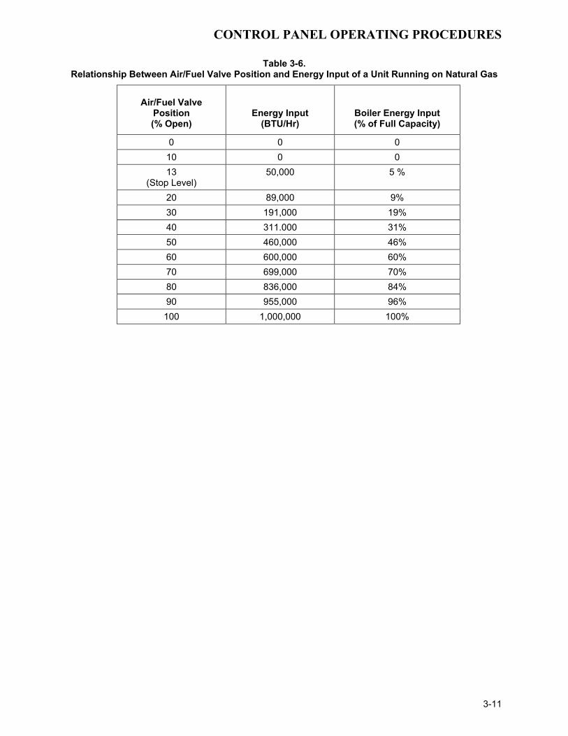
Note that the energy input of the boiler is not linearly related to the valve position percentage (Air/Fuel Valve Position). Refer to Table 3-6 for the relationship between the energy input and valve position percentage for a unit running on natural gas.
CONTROL PANEL OPERATING PROCEDURES
3-11
Table 3-6. Relationship Between Air/Fuel Valve Position and Energy Input of a Unit Running on Natural Gas
Air/Fuel Valve Position (% Open)
Energy Input (BTU/Hr)
Boiler Energy Input (% of Full Capacity)
0 0 0 10 0 0 13
(Stop Level) 50,000 5 %
20 89,000 9% 30 191,000 19% 40 311.000 31% 50 460,000 46% 60 600,000 60% 70 699,000 70% 80 836,000 84% 90 955,000 96% 100 1,000,000 100%
INITIAL START-UP
4-1
SECTION 4 - INITIAL START- UP
4.1 INITIAL START- UP REQUIREMENTS The initial start-up of the KC-1000 Low NOx Boiler is comprised of the following steps: • Installation completed 100% • Combustion calibration • Proper setting of controls and limits • Temperature calibration • Safety device testing (see Section 5) Installation procedures should be completed 100% before performing initial start-up. Also, the initial start-up must be complete prior to putting the unit into service. Starting a unit without the proper piping, venting, or electrical systems can be dangerous and void the product’s warranty. These start-up instructions should be precisely followed in order for the unit to operate safely, at a high thermal efficiency, and with low flue gas emissions. Initial unit start-up must be performed ONLY by AERCO factory trained start-up and service personnel. After following the steps in this section, it will be necessary to perform the safety device test procedures in Section 5 to complete the initial unit start-up. An AERCO Gas Fired Startup Sheet included with each KC-1000 must be completed for each unit for warranty validation and a copy must be returned promptly to AERCO at: AERCO International, Inc. 159 Paris Ave. Northvale, NJ 07647
WARNING! DO NOT ATTEMPT TO FIRE THE UNIT WITHOUT FULL WATER LEVEL. THIS CAN SERIOUSLY DAMAGE THE UNIT AND MAY RESULT IN PERSONAL INJURY OR PROPERTY DAMAGE. THIS IS NOT COVERED BY WARRANTY.
CAUTION! All installation procedures in Section 2 must be completed before attempting to start the unit.
4.2 TOOLS AND INSTRUMENTATION FOR COMBUSTION CALIBRATION To properly perform combustion calibration on a KC Boiler equipped with a low NOx burner, the proper instruments and tools must be used and correctly installed on the unit. The following paragraphs outline the necessary tools and instrumentation as well as their installation. 4.2.1 REQUIRED TOOLS AND INSTRUMENTATION The following tools and instrumentation are necessary to perform combustion calibration of a low NOx unit: 1. Digital Combustion Analyzer - Oxygen
accuracy to ± 0.4%; Carbon Monoxide and NOx resolution to 1 PPM.
2. A 16" W.C. manometer and plastic tubing. 3. One 1/4” and two 1/8” NPT-to-barbed fittings
for use with manometers. 4. Small and large flat blade screwdrivers. 5. 7/16" open end wrench and small adjustable
wrenches. 6. Tube of silicone adhesive
4.2.2 INSTALLING THE SUPPLY GAS MANOMETER 1. Close the main manual gas supply valve up
stream of the unit. 2. Remove the 1/4" NPT pipe plug from the
port on the inlet side of the safety shut off valve (see Figure 4.1).
3. Install a barbed fitting into the pipe plug
tapping. 4. Attach one end of a length of plastic tubing
to the barbed fitting and one end to the 16" W.C. manometer.

INITIAL START-UP
4-2
SSOV
1/8" NPT PLUG(INSTALLMANOMETERHERE)
Figure 4.1
1/8” Gas Plug Location
4.2.3 PREPARING THE FLUE VENT PROBE HOLE 1. If the unit has been installed using the
recommended AL29-4C vent, there will be a 3/8” hole, 18” to 24” above the exhaust manifold. The outer vent section, that covers vent connections must be loosened and moved to uncover the hole (see Figure 4.2).
2. If equipped with one, adjust the stop on the
combustion analyzer probe so that it extends into the flue gas flow without hitting the opposite wall of the flue. Do not insert the probe at this time.
3/8" - 1/2"HOLE FOR
COMBUSTIONANALYZER
PROBE
EXHAUSTMANIFOLD
12" - 18"
Figure 4.2
Analyzer Probe Hole Location
IMPORTANT
The unit is shipped from the factory set up for either natural gas or propane, as specified by the Style No. on the Sales Order. If desired, the unit can be easily switched from one fuel type to the other using the regulator spring change procedure in Appendix I. For propane units, disregard paragraph 4.3 and proceed to paragraph 4.4.
4.3 NATURAL GAS COMBUSTION CALIBRATION The KC-1000 is shipped combustion calibrated from the factory. Recalibration as part of a start-up is necessary due to differences in altitude, gas BTU content, gas supply piping and supply regulators. Factory test data sheets are shipped with each unit as a reference. The following combustion calibration procedure closely follows the factory procedure. By following this procedure, readjustment of combustion will be kept to a minimum.
1. Open the supply and return valves to the unit and ensure that the system pumps are running.
2. Open the gas supply valve(s) to the unit. 3. If a lockup style regulator is installed as a
gas supply regulator, adjust the gas supply until a reading of 12” W.C. static pressure is obtained.
4. Set the ON/OFF switch to the OFF position.
Turn on AC power to the unit. The display will show LOSS OF POWER and the time and date.
5. Set the unit to the Manual Mode by pressing
the AUTO/MAN switch. A flashing Manual Valve Position message will be displayed with the present position in % open. Also, the MANUAL LED will light.
NOTE: For a review of the control panel operating procedures, refer to Section 3. 6. Adjust the valve position to 0% by pressing
the ▼ arrow key. 7. Set the ON/OFF switch to the ON position. 8. Change the valve position to 25% using the
▲ arrow key. This will put the unit into the starting sequence.
NOTE:

INITIAL START-UP
4-3
On initial start-up, or return to service from a fault condition, the unit will remain at a 29% valve position for two-minutes. 9. Following the warm-up period, increase the
valve position in 20% increments while monitoring the gas pressure after every increase. If gas pressure dips below 8.8” W.C. for FM gas trains and 9.2” for IRI gas trains at any input valve position percentage, stop and raise the pressure. Once 100% is reached, adjust the gas pressure for 8.8” W.C. (FM) or 9.2” W.C. (IRI).
NOTE: If 8.8” W.C. for FM gas trains or 9.2” W.C. for IRI gas trains cannot be obtained at the 100% valve position, it will be necessary to stop calibration and contact the local AERCO representative in your area. Running the unit on insufficient gas pressure will void the warranty. 10. Once 8.8” W.C. or 9.2” W.C. is set at the
100% level, change the valve position to 30%. Insert the combustion analyzer probe into the stack.
NOTE: Always approach a valve position percentage from the same direction, (i.e., 100% to 30%, 30% to 20%, etc.). Whenever going to an increased valve position from below (i.e., 20% to 30%), first go above and then back down to the desired valve position. This is necessary due to hysteresis in the air/fuel stepper motor. Hysteresis causes the air/fuel valve to stop in a slightly different position if the valve position percentage is approached from below or above. This results in a difference in oxygen readings for the same valve position percentage causing unnecessary recalibration. 11. Allow enough time for the combustion
analyzer to settle. Compare the measured oxygen level to the oxygen range for intake air temperature in Table 1. Also, ensure that the carbon monoxide (CO) and nitrogen oxide (NOx) readings do not exceed the values shown.
12. If the measured oxygen level, CO and NOx
emissions are within the ranges shown in Table 1, no adjustment is necessary. Proceed to step 19.
Table 1 Combustion Oxygen Levels for a 30%
Valve Position
Inlet Air Temp
Oxygen (±0.2%)
Carbon Monoxide
*NOx
-25°F 7.8% <100 ppm <30 ppm -10°F 7.5% <100 ppm <30 ppm 0°F 7.4% <100 ppm <30 ppm
10°F 7.2% <100 ppm <30 ppm 25°F 6.9% <100 ppm <30 ppm 40°F 6.5% <100 ppm <30 ppm 55°F 6.4% <100 ppm <30 ppm 70°F 6.2% <100 ppm <30 ppm 85°F 5.9% <100 ppm <30 ppm
100°F 5.7% <100 ppm N/A
* NOx readings corrected to 3% oxygen.
13. If the measured oxygen level is not within the range listed in Table 1, remove the regulator cap and cap gasket from the differential pressure regulator (see Figure 4.3) and proceed to step 14.
DIFFERENTIAL PRESSUREREGULATOR
REGULATOR CAP
CAP GASKET
Figure 4.3 Differential Pressure Regulator
14. Use a flat-tip screwdriver to adjust the
differential pressure regulator. Turn the screwdriver:
• counterclockwise to increase the oxygen level
• clockwise to decrease the oxygen level

INITIAL START-UP
4-4
15. Replace the regulator cap and cap gasket and wait for the analyzer reading to settle.
16. When the analyzer reading settles, compare
the new oxygen reading to Table 1. 17. If necessary, repeat the adjustment until the
oxygen level is within the range specified in Table 1.
18. Replace the regulator cap and cap gasket.
NOTE: Adjust only the differential regulator at 30% control signal; do not adjust the air shutter. 19. Once the oxygen level is within the specified
range at 30%, change the valve position to 16%.
20. Oxygen levels at the 16% valve position
should be as shown in Table 2. Also, ensure that the CO and NOx readings do not exceed the values shown. No adjustment should be necessary. Contact the Factory if the oxygen, CO or NOx levels are not within the specified ranges.
Table 2 Combustion Oxygen Levels for a 16%
Valve Position
Inlet Air Temp
Oxygen (±0.2%)
Carbon Monoxide
*NOx
-25°F <10% <100 ppm <30 ppm -10°F <10% <100 ppm <30 ppm 0°F <10% <100 ppm <30 ppm
10°F <10% <100 ppm <30 ppm 25°F <10% <100 ppm <30 ppm 40°F <10% <100 ppm <30 ppm 55°F <10% <100 ppm <30 ppm 70°F <10% <100 ppm <30 ppm 85°F <10% <100 ppm <30 ppm
100°F <10% <100 ppm N/A
* NOx readings corrected to 3% oxygen.
NOTE: At a 100% valve position, the KC1000 will not operate reliably at inlet air temperatures below 55°F if the Cold Air Damper (P/N 99026) is not installed. See paragraphs 2.8.2 and 2.8.3.
21. Change the valve position to 100% and allow the combustion analyzer to settle.
22. If the optional Cold Air Damper (P/N 99026) is installed, compare the measured oxygen level with the levels in Table 3. If the Cold Air Damper is not installed, compare the oxygen levels with the readings in Table 3A.
Table 3 Combustion Oxygen Levels for a 100% Valve Position With Cold Air Damper
Inlet Air Temp
Oxygen (±0.2%)
Carbon Monoxide
*NOx
-25°F 6.7 <100 ppm <30 ppm -10°F 6.5 <100 ppm <30 ppm 0°F 6.4 <100 ppm <30 ppm
10°F 6.3 <100 ppm <30 ppm 25°F 6.2 <100 ppm <30 ppm 40°F 6.1 <100 ppm <30 ppm 55°F 5.9 <100 ppm <30 ppm 70°F 5.8 <100 ppm <30 ppm 85°F 5.6 <100 ppm <30 ppm
100°F 4.7 <100 ppm N/A
* NOx readings corrected to 3% oxygen.
Table 3A Combustion Oxygen Levels for a 100%
Valve Position Without Cold Air Damper
Inlet Air Temp
Oxygen (±0.2%)
Carbon Monoxide
*NOx
55°F 7.5% <100 ppm <30 ppm 70°F 6.5% <100 ppm <30 ppm 85°F 5.5% <100 ppm <30 ppm
100°F 4.5% <100 ppm N/A
* NOx readings corrected to 3% oxygen.
23. If the measured oxygen reading is below the oxygen range in Table 3 (or 3A), loosen the two bolts that secure the inlet air shutter to the unit using a 7/16” wrench (see Figure 4.4). Open the shutter 1/4” to 1/2” to increase the oxygen level, then tighten the nuts.
24. Wait for the analyzer to settle, then compare
the new oxygen reading to Table 3 (or 3A). Repeat the inlet air shutter adjustment until the oxygen is within the specified range. Also, ensure that the CO and NOx emissions do not exceed the values shown. Firmly tighten the inlet air shutter locking nuts when finished.

INITIAL START-UP
4-5
BLOWEROUTLET
BLOWERINLET
SCREEN
SHUTTER
SHUTTER LOCKING NUTS
Figure 4.4
Air Shutter Locking Nut Location
REMINDER:
At 30% valve position, adjust only the differential pressure regulator. At 100% valve position, adjust only the inlet air shutter.
25. If the measured oxygen reading is above the oxygen range in Table 3 (or 3A), loosen the two 7/16" locking nuts securing the inlet air shutter. Close the air shutter 1/4” to 1/2” to decrease the oxygen level and tighten the two nuts.
26. Allow the analyzer to settle then compare
the new oxygen reading to Table 3 (or 3A). 27. Repeat the adjustment until the oxygen is
within the specified range. Also, ensure that the CO and NOx readings do not exceed the values shown. Firmly tighten the inlet air shutter locking nuts when finished.
NOTE:
Adjust the inlet air shutter only at 100% valve position. Do Not adjust the differential pressure regulator. 28. Change the valve position to 30%. Allow
time for the combustion analyzer to settle. Check the measured oxygen level, CO and NOx emissions to ensure that they are still within the ranges shown in Table 1.
29. Continue these procedures until all oxygen
levels are within the ranges specified in Tables 1, 2, 3 (or 3A).
30. Record all readings on the AERCO start-up sheet provided with each unit. Proceed to paragraph 4.5 when all natural gas combustion calibration procedures are completed.
IMPORTANT The unit is shipped from the factory set up for either natural gas or propane, as specified by the Style No. on the Sales Order. If desired, the unit can be easily switched from one fuel to the other using the regulator spring change procedure in Appendix I. Since the required gas supply pressures for propane differ from those required for natural gas, the Propane Combustion Calibration procedures are repeated in their entirety in paragraph 4.4.
4.4 PROPANE COMBUSTION CALIBRATION The KC-1000 is shipped combustion calibrated from the factory. Recalibration as part of a start-up is necessary due to differences in altitude, gas BTU content, gas supply piping and supply regulators. Factory test data sheets are shipped with each unit as a reference. Prior to starting these procedures, ensure that the KC1000 has been set up as specified in paragraphs 4.2 through 4.2.4. The following combustion calibration procedure closely follows the factory procedure. By following this procedure, readjustment of combustion will be kept to a minimum.
1. Open the supply and return valves to the unit and ensure that the system pumps are running.
2. Open the gas supply valve(s) to the unit. 3. If a lockup style regulator is installed as a
gas supply regulator, adjust the gas supply until a reading of 11” W.C. static pressure is obtained.
4. Set the ON/OFF switch to the OFF position.
Turn on AC power to the unit. The display will show LOSS OF POWER and the time and date.

INITIAL START-UP
4-6
5. Set the unit to the Manual Mode by pressing the AUTO/MAN switch. A flashing Manual Valve Position message will be displayed with the present position in % open. Also, the MANUAL LED will light.
NOTE: For a review of the control panel operating procedures, refer to Section 3.
6. Adjust the valve position to 0% by pressing
the ▼ arrow key. 7. Set the ON/OFF switch to the ON position. 8. Change the valve position to 25% using the
▲ arrow key. This will put the unit into the starting sequence.
NOTE:
On initial start-up, or return to service from a fault condition, the unit will remain at a 29% valve position for two-minutes. 9. Following the warm-up period, increase the
valve position in 20% increments while monitoring the gas pressure after every increase. If gas pressure dips below 7.7” W.C. for FM gas trains and 8.1” for IRI gas trains at any input valve position percentage, stop and raise the pressure. Once 100% is reached, adjust the gas pressure for 7.7” (FM) W.C. or 8.1” W.C. (IRI).
NOTE: If 7.7” W.C. for FM gas trains or 8.1” W.C. for IRI gas trains cannot be obtained at the 100% valve position, it will be necessary to stop calibration and contact the local AERCO representative in your area. Running the unit on insufficient gas pressure will void the warranty 10. Once 7.7” W.C. or 8.1” W.C. is set at the
100% level, change the valve position to 30%. Insert the combustion analyzer probe into the stack.
NOTE: Always approach a valve position percentage from the same direction, (i.e., 100% to 30%, 30% to 20%, etc.). Whenever going to an increased valve position from below (i.e., 20% to 30%), first go above and then back down to the desired valve position. This is necessary due to hysteresis in the air/fuel stepper motor. Hysteresis causes the air/fuel valve to stop in a slightly different position if the valve position percentage is approached from below or above. This results in a difference in oxygen readings for the same valve position percentage causing unnecessary recalibration. 11. Allow enough time for the combustion
analyzer to settle. Compare the measured oxygen level to the oxygen range for intake air temperature in Table 4. Also, ensure that the carbon monoxide (CO) and nitrogen oxide (NOx) readings do not exceed the values shown.
Table 4
Combustion Oxygen Levels for a 30% Valve Position
Inlet Air Temp
Oxygen (±0.2%)
Carbon Monoxide
*NOx
-25°F 7.8% <100 ppm <30 ppm -10°F 7.5% <100 ppm <30 ppm 0°F 7.4% <100 ppm <30 ppm
10°F 7.2% <100 ppm <30 ppm 25°F 6.9% <100 ppm <30 ppm 40°F 6.5% <100 ppm <30 ppm 55°F 6.4% <100 ppm <30 ppm 70°F 6.2% <100 ppm <30 ppm 85°F 5.9% <100 ppm <30 ppm
100°F 5.7% <100 ppm N/A
* NOx readings corrected to 3% oxygen. 12. If the measured oxygen level, CO and NOx
emissions are within the ranges shown in Table 4, no adjustment is necessary. Proceed to step 19.
13. If the measured oxygen level is not within
the range listed in Table 1, remove the regulator cap and cap gasket from the differential pressure regulator (see Figure 4.3) and proceed to step 14.
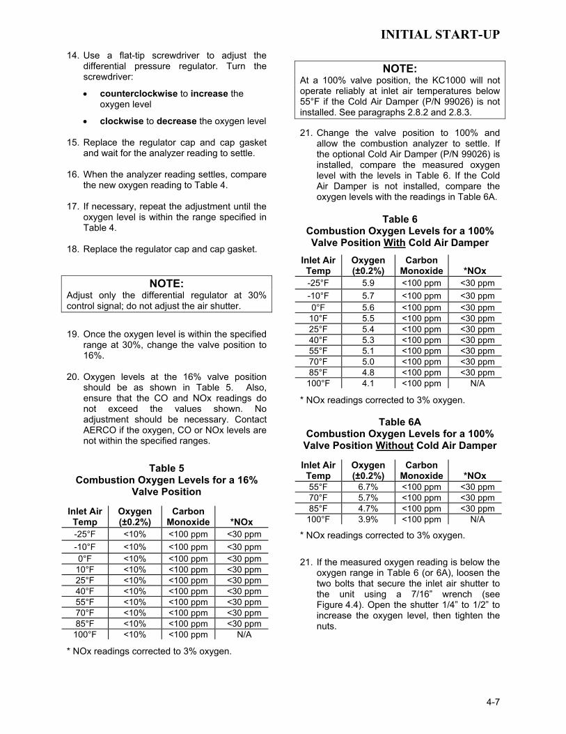
INITIAL START-UP
4-7
14. Use a flat-tip screwdriver to adjust the differential pressure regulator. Turn the screwdriver:
• counterclockwise to increase the oxygen level
• clockwise to decrease the oxygen level 15. Replace the regulator cap and cap gasket
and wait for the analyzer reading to settle. 16. When the analyzer reading settles, compare
the new oxygen reading to Table 4. 17. If necessary, repeat the adjustment until the
oxygen level is within the range specified in Table 4.
18. Replace the regulator cap and cap gasket.
NOTE: Adjust only the differential regulator at 30% control signal; do not adjust the air shutter.
19. Once the oxygen level is within the specified
range at 30%, change the valve position to 16%.
20. Oxygen levels at the 16% valve position
should be as shown in Table 5. Also, ensure that the CO and NOx readings do not exceed the values shown. No adjustment should be necessary. Contact AERCO if the oxygen, CO or NOx levels are not within the specified ranges.
Table 5 Combustion Oxygen Levels for a 16%
Valve Position
Inlet Air Temp
Oxygen (±0.2%)
Carbon Monoxide
*NOx
-25°F <10% <100 ppm <30 ppm -10°F <10% <100 ppm <30 ppm 0°F <10% <100 ppm <30 ppm
10°F <10% <100 ppm <30 ppm 25°F <10% <100 ppm <30 ppm 40°F <10% <100 ppm <30 ppm 55°F <10% <100 ppm <30 ppm 70°F <10% <100 ppm <30 ppm 85°F <10% <100 ppm <30 ppm
100°F <10% <100 ppm N/A
* NOx readings corrected to 3% oxygen.
NOTE:
At a 100% valve position, the KC1000 will not operate reliably at inlet air temperatures below 55°F if the Cold Air Damper (P/N 99026) is not installed. See paragraphs 2.8.2 and 2.8.3. 21. Change the valve position to 100% and
allow the combustion analyzer to settle. If the optional Cold Air Damper (P/N 99026) is installed, compare the measured oxygen level with the levels in Table 6. If the Cold Air Damper is not installed, compare the oxygen levels with the readings in Table 6A.
Table 6 Combustion Oxygen Levels for a 100% Valve Position With Cold Air Damper
Inlet Air Temp
Oxygen (±0.2%)
Carbon Monoxide
*NOx
-25°F 5.9 <100 ppm <30 ppm -10°F 5.7 <100 ppm <30 ppm 0°F 5.6 <100 ppm <30 ppm
10°F 5.5 <100 ppm <30 ppm 25°F 5.4 <100 ppm <30 ppm 40°F 5.3 <100 ppm <30 ppm 55°F 5.1 <100 ppm <30 ppm 70°F 5.0 <100 ppm <30 ppm 85°F 4.8 <100 ppm <30 ppm
100°F 4.1 <100 ppm N/A
* NOx readings corrected to 3% oxygen.
Table 6A Combustion Oxygen Levels for a 100%
Valve Position Without Cold Air Damper
Inlet Air Temp
Oxygen (±0.2%)
Carbon Monoxide
*NOx
55°F 6.7% <100 ppm <30 ppm 70°F 5.7% <100 ppm <30 ppm 85°F 4.7% <100 ppm <30 ppm
100°F 3.9% <100 ppm N/A
* NOx readings corrected to 3% oxygen.
21. If the measured oxygen reading is below the oxygen range in Table 6 (or 6A), loosen the two bolts that secure the inlet air shutter to the unit using a 7/16” wrench (see Figure 4.4). Open the shutter 1/4” to 1/2” to increase the oxygen level, then tighten the nuts.

INITIAL START-UP
4-8
22. Wait for the analyzer to settle and then compare the new oxygen reading to Table 6 (or 6A). Repeat the inlet air shutter adjustment until the oxygen is within the specified range. Also, ensure that the CO and NOx emissions do not exceed the values shown. Firmly tighten the inlet air shutter locking nuts when finished.
REMINDER:
At 30% valve position, adjust only the differential pressure regulator. At 100% valve position, adjust only the inlet air shutter.
23. If the measured oxygen reading is above the
oxygen range in Table 6 (or 6A), loosen the two 7/16" locking nuts securing the inlet air shutter. Close the air shutter 1/4” to 1/2” to decrease the oxygen level and tighten the two nuts.
24. Allow the analyzer to settle then compare
the new oxygen reading to Table 6 (or 6A). 25. Repeat the adjustment until the oxygen is
within the specified range. Also, ensure that the CO and NOx readings do not exceed the values shown. Firmly tighten the inlet air shutter locking nuts when finished.
NOTE:
Adjust the inlet air shutter only at 100% valve position. Do Not adjust the differential pressure regulator. 26. Change the valve position to 30%. Allow
time for the combustion analyzer to settle. Check the measured oxygen level, CO and NOx emissions to ensure that they are still within the ranges shown in Table 4.
27. Continue these procedures until all oxygen
levels are within the ranges specified in Tables 4, 5 and 6 (or 6A).
28. Record all readings on the AERCO start-up
sheet provided with each unit. Proceed to paragraph 4.5 when all propane combustion calibration procedures are completed.
4.5 UNIT REASSEMBLY Once combustion calibration is set properly, the unit can be re-assembled for permanent operation. 1. Set the ON/OFF switch to the OFF position.
Disconnect the AC power supply from the unit.
2. Shut off the gas supply to the unit. 3. Remove the differential pressure regulator
cap and cap gasket (see Figure 4.3). 4. Apply a drop of silicone adhesive to the
regulator adjusting screw to lock its setting. 5. Reinstall the cap and gasket on the
regulator. Tighten the cap using a screwdriver or wrench.
6. Remove all of the manometers and barbed
fittings and reinstall the pipe plugs using a suitable thread compound.
7. Remove the combustion analyzer probe
from the vent hole. Seal the probe hole and replace the vent connection cover.
8. Replace the unit’s panels and hood.
4.6 OVER TEMPERATURE LIMIT SWITCH ADJUSTMENTS There are two Over-Temperature Limit switches that turn off the unit when the outlet water temperature becomes too hot. The lower over-temperature limit switch is adjustable and should be adjusted 20°F to 40°F above the operating header temperature. The upper over-temperature limit switch is a manual reset device and is not adjustable. It will shut the unit off if the water temperature reaches 240°F. DO NOT attempt to adjust its setpoint. To adjust the lower over temperature switch limit switch, proceed as follows: 1. Remove the wing nut from the top center of
the shell cap. Lift the cap off the shell. 2. The two over-temperature limit switches are
located at the top of the shell (Figure 4.5). DO NOT adjust the upper switch which has been factory preset. Adjust the lower switch between 20°F to 40°F higher than the maximum header temperature the unit may reach.
3. Replace the shell cap and wing nut.

INITIAL START-UP
4-9
OVER-TEMPERATURESWITCHES
SHELL SENSOR
209
TEMPERATURE SWITCH DETAILS
137
HARNESS
136
FROM SHELL
NC
NC
CNO
C
LIQUID LEVEL SWITCH
OVER TEMP. SWITCH
Figure 4.5 Over Temperature Limit Switch Location


MODE OF OPERATION
5-1
SECTION 5 - MODE OF OPERATION
5.1 INTRODUCTION The following paragraphs provide detailed descriptions of the six different modes of operation for the KC1000 Boiler. Each unit is shipped from the factory tested and configured for the ordered mode of operation. All temperature related parameters are at factory defaults and work well in most applications. However, it may be necessary to change certain parameters to customize the unit to the system. A complete listing and descriptions of the temperature related parameters are included in Appendix A. Factory defaults are listed in Appendix E. After reading this section, parameters can be customized to suit the needs of the specific application.
5.2 INDOOR/OUTDOOR RESET MODE This mode of operation is based on outside air temperatures. As the outside air temperature decreases, the supply header temperature will increase and vice versa. For this mode, it is necessary to install an outside air sensor as well as select a building reference temperature and a reset ratio.
5.2.1 RESET RATIO Reset ratio is an adjustable number from 0.1 to 9.9. Once it is adjusted, the supply header temperature will increase by that number for each degree that the outside air temperature decreases. For instance, if a reset ratio of 1.6 is used, for each degree that outside air temperature decreases the supply header temperature will increase by 1.6 degrees.
5.2.2. BUILDING REFERENCE TEMPERATURE This is a temperature from 40°F to 240°F. Once selected, it is the temperature that the system references to begin increasing its temperature. For instance, if a reset ratio of 1.6 is used and we select a building reference temperature of 70°F, then at an outside temperature of 69°F, the supply header temperature will increase by 1.6° to 71.6°F.
5.2.3 OUTDOOR AIR TEMPERATURE SENSOR INSTALLATION The outdoor air temperature sensor must be mounted on the North side of the building in an area where the average outside air temperature
is expected. The sensor must be shielded from the sun's direct rays, as well as from direct impingement by the elements. If a cover or shield is used, it must allow free air circulation. The sensor may be mounted up to 200 feet from the unit. Sensor connections are made inside the Input/Output (I/O) Box on the left side of the KC1000 Boiler. Connections are made at the terminals labeled OUTDOOR SENSOR IN and SENSOR COMMON inside the I/O Box using shielded 18 to 22 AWG wire. A wiring diagram is provided on the cover of the I/O Box. Refer to Section 2, paragraph 2.6.2 for additional wiring information.
5.2.4 INDOOR/OUTDOOR STARTUP 1. Refer to the indoor/outdoor reset ratio charts
in Appendix D. 2. Choose the chart corresponding to the
desired building reference temperature. 3. Go down the left column of the chart to the
coldest design outdoor air temperature expected in your area.
NOTE: A design engineer typically provides design outdoor air temperature and supply header temperature data 4. Once the design outdoor air temperature is
chosen, go across the chart to the desired supply header temperature for the design temperature chosen in step 3.
5. Next, go up that column to the Reset Ratio
row to find the corresponding reset ratio. 6. Access the Configuration Menu and scroll
through it until the display shows Bldg Ref Temp (Building Reference Temperature).
7. Press the CHANGE key. The display will
begin to flash. 8. Use the ▲ and ▼ arrow keys to select the
desired building reference temperature. 9. Press ENTER to save any changes. 10. Next, scroll through the Configuration Menu
until the display shows Reset Ratio.
MODE OF OPERATION
5-2
11. Press the CHANGE key. The display will begin to flash.
12. Use the ▲ and ▼ arrow keys to select the
reset ratio determined in step 5. 13. Press ENTER to save the change. Refer to paragraph 3.3 for detailed instructions on menu changing.
5.3 CONSTANT SETPOINT MODE The Constant Setpoint mode is used when a fixed header temperature is desired. Common uses of this mode of operation include water source heat pump loops, and indirect heat exchangers for potable hot water systems or processes. There are no external sensors necessary to operate in this mode. While it is necessary to set the desired setpoint temperature, it is not necessary to change any other temperature-related functions. The unit is factory preset with settings that work well in most applications. Prior to changing any temperature-related parameters, other than the setpoint, it is suggested that an AERCO representative be contacted. For a complete listing of factory defaults and descriptions of temperature related functions, see Appendices A and E.
5.3.1 SETTING THE SETPOINT The setpoint temperature of the unit is adjustable from 40°F to 240°F. To set the unit for operation in the Constant Setpoint Mode, the following menu settings must be made in the Configuration Menu: MENU OPTION SETTING
Boiler Mode Constant Setpoint Internal Setpt Select desired setpoint
using ▲ and ▼ arrow keys (40°F to 240°F)
Refer to paragraph 3.3 for detailed instructions on changing menu options.
5.4 REMOTE SETPOINT MODES The unit’s setpoint can be remotely controlled by an Energy Management System (EMS) or Building Automation System (BAS). The Remote Setpoint can be driven by a current or voltage signal within the following ranges: 4-20 mA/1-5 Vdc
0-20 mA/0-5 Vdc
The factory default setting for the Remote Setpoint mode is 4 - 20 mA/1 - 5 Vdc. With this setting, a 4 to 20 mA/1 to 5 Vdc signal, sent by an EMS or BAS, is used to change the unit's setpoint. The 4 mA/1V signal is equal to a 40°F setpoint while a 20 mA /5V signal is equal to a 240°F setpoint. When a 0 to 20 mA/0 to 5 Vdc signal is used, 0 mA is equal to a 40°F setpoint.
In addition to the current and voltage signals described above, the Remote Setpoint mode can also driven by a RS485 Modbus Network signal from an EMS or BAS.
The Remote Setpoint modes of operation can be used to drive single as well as multiple units.
NOTE: If a voltage, rather than current signal is used to control the remote setpoint, a DIP switch adjustment must be made on the CPU Board in the Control Box. Contact your local AERCO representative for details.
In order to enable the Remote Setpoint Mode, the following menu setting must be made in the Configuration Menu:
MENU OPTION SETTING
Boiler Mode Remote Setpoint
Remote Signal 4-20mA/1-5V, 0-20mA/0-5V, or Network
Refer to paragraph 3.3 for detailed instructions on changing menu options.

MODE OF OPERATION
5-3
If the Network setting is selected for RS485 Modbus operation, a valid Comm Address must be entered in the Setup Menu. Refer to Modbus Communication Manual GF-114 for additional information.
While it is possible to change the settings of temperature related functions, the unit is factory preset with settings that work well in most applications. It is suggested that an AERCO representative be contacted, prior to changing any temperature related function settings. For descriptions of temperature-related functions and their factory defaults, refer to Appendices A and E.
5.4.1 REMOTE SETPOINT FIELD WIRING The only wiring connections necessary for the Remote Setpoint mode are connection of the remote signal leads from the source to the unit’s I/O Box. The I/O Box is located on the front panel of the Benchmark Boiler. For either a 4-20mA/0-5V or a 0-20mA/0-5V setting, the connections are made at the ANALOG IN terminals in the I/O Box. For a Network setting, the connections are made at the RS-485 COMM terminals in the I/O Box. The signal must be floating, (ungrounded) at the I/O Box and the wire used must be a two wire shielded pair from 18 to 22 AWG. Polarity must be observed. The source end of the shield must be connected at the source. When driving multiple units, each unit’s wiring must conform to the above.
5.4.2 REMOTE SETPOINT STARTUP Since this mode of operation is factory preset and the setpoint is being externally controlled, no startup instructions are necessary. In this mode, the REMOTE LED will light when the external signal is present.
To operate the unit in the Manual mode, press the AUTO/MAN switch. The REMOTE LED will go off and the MANUAL LED will light.
To change back to the Remote Setpoint mode, simply press the AUTO/MAN switch. The REMOTE LED will again light and the MANUAL LED will go off.
5.5 DIRECT DRIVE MODES The unit’s valve position can be changed by a remote signal which is typically sent from an Energy Management System (EMS) or from a Building Automation System (BAS). The Direct Drive mode can be driven by a current or voltage signal within the following ranges:
4-20 mA/1-5 Vdc
0-20 mA/0-5 Vdc
The factory default setting for the Direct Drive mode is 4-20 mA/1-5 Vdc. With this setting, a 4 to 20 mA signal, sent by an EMS or BAS is used to change the unit’s valve position from 0% to 100%. A 4 mA/1V signal is equal to a 0% valve position, while a 20 mA /5V signal is equal to a 100% valve position. When a 0-20 mA/0-5 Vdc signal is used, zero is equal to a 0% valve position.
In addition to the current and voltage signals described above, the Direct Drive mode can also driven by a RS485 Modbus Network signal from an EMS or BAS.
When in a Direct Drive mode, the unit is a slave to the EMS or BAS and does not have a role in temperature control. Direct Drive can be used to drive single, or multiple units.
NOTE: If a voltage, rather than current signal is used to control the valve position, a DIP switch adjustment must be made on the PMC Board in the Control Box. Contact your local AERCO representative for details.
To enable the Direct Drive Mode, the following menu setting must be made in the Configuration Menu:
MENU OPTION SETTING
Boiler Mode Direct Drive
Remote Signal 4-20mA/1-5V, 0-20mA/0-5V, or Network
Refer to paragraph 3.3 for instructions on changing menu options.
MODE OF OPERATION
5-4
If the Network setting is selected for RS485 Modbus operation, a valid Comm Address must be entered in the Setup Menu. Refer to Modbus Communication Manual GF-114 for additional information.
5.5.1 DIRECT DRIVE FIELD WIRING The only wiring connections necessary for Direct Drive mode are connection of the remote signal leads from the source to the unit’s I/O Box. For either a 4-20mA/0-5V or a 0-20mA/0-5V setting, the connections are made at the ANALOG IN terminals in the I/O Box. For a Network setting, the connections are made at the RS-485 COMM terminals in the I/O Box. The signal must be floating, (ungrounded) at the I/O Box and the wire used must be a two wire shielded pair from 18 to 22 AWG. Polarity must be observed. The source end of the shield must be connected at the source. When driving multiple units, each unit’s wiring must conform to the above.
5.5.2 DIRECT DRIVE STARTUP Since this mode of operation is factory preset and the valve position is being externally controlled, no startup instructions are necessary. In this mode, the REMOTE LED will light when the signal is present.
To operate the unit in manual mode, press the AUTO/MAN switch. The REMOTE LED will go off and the MANUAL LED will light.
To change back to the Direct Drive mode, simply press the AUTO/MAN switch. The REMOTE LED will again light and the MANUAL LED will go off.
5.6 BOILER MANAGEMENT SYSTEM (BMS) MODE
NOTE BMS Model 168 can utilize either pulse width modulation (PWM) or RS485 Modbus signaling to the Boiler. BMS II Model 5R5-384 can utilize only RS485 signaling to the Boiler.
The BMS mode of operation is used in conjunction with an AERCO Boiler Management System. The BMS mode is used when it is desired to operate multiple units in the most efficient manner possible. The BMS can control up to 40 boilers; 8 via pulse width modulation (PWM) and up to 32 via Modbus (RS485) network communication. For BMS programming and operation, see GF-108M (BMS Model 168) and GF-124 (BMS II Model 5R5-384), BMS Operations Guides. For operation via an RS485
Modbus network, refer to Modbus Communication Manual GF-114.
To enable the BMS Mode, the following menu settings must be made in the Configuration Menu:
MENU OPTION SETTING
Boiler Mode Direct Drive
Remote Signal BMS (PWM Input) or Network (RS485)
Refer to paragraph 3.3 for instructions on changing menu options.
5.6.1 BMS EXTERNAL FIELD WIRING
Wiring connections for BMS control using PWM signaling are made between connector JP2 on the BMS panel (boilers 1 through 8), and the B.M.S. (PWM) IN terminals in the I/O Box on the front of the Benchmark Boilers. Refer to the wiring diagram provided on the cover of the I/O Box.
Wiring connections for RS485 Modbus control are made between connector JP11 on the BMS (boilers 9 through 40) and the RS485 COMM terminals in the I/O Box on the front of the unit.
Wire the units using shielded twisted pair wire between 18 and 22 AWG. Observe the proper polarity for the B.M.S. (PWM) IN and/or RS485 COMM wiring connections. Shields should be terminated only at the BMS and the boiler end must be left floating. Each unit’s wiring must conform to the above.
5.6.2 BMS SETUP AND STARTUP This mode of operation is factory preset and the AERCO BMS controls the valve position. There are no setup instructions for each individual unit.
To operate the unit in manual mode, press the AUTO/MAN switch. The REMOTE LED will go off and the MANUAL LED will light
To change back to the BMS mode, simply press the AUTO/MAN switch. The REMOTE LED will again light and the MANUAL LED will go off.

MODE OF OPERATION
5-5
5.7 COMBINATION CONTROL SYSTEM (CCS)
NOTE Only BMS Model 168 can be utilized for the Combination Mode, not the BMS II (Model 5R5-384).
A Combination Control System (CCS) is one that uses multiple boilers to cover both space-heating and domestic hot water needs. An AERCO Boiler Management System (BMS) Model 168 and a Combination Control Panel (CCP) are necessary to configure this system. Typically, an adequate number of boilers are installed to cover the space-heating load on the design day, however one or more units are used for the domestic hot water load.
The theory behind this type of system is that the maximum space-heating load and the maximum domestic hot water load do not occur simultane-ously. Therefore, boilers used for the domestic hot water are capable of switching between constant setpoint and BMS modes of operation. These boilers are the combination units and are referred to as the combo boilers. The combo boilers heat water to a constant setpoint temperature. That water is then circulated through a heat exchanger in a domestic hot water storage tank.
When the space-heating load is such that all the space-heating boilers are at 100% valve position, the BMS will then ask the Combination Control Panel for the domestic boilers to become space-heating boilers. Provided the domestic hot water load is satisfied, the combo (hot water) boilers will then become space-heating boilers. If the domestic hot water load is not satisfied, the combo boiler(s) remain on the domestic hot water load. If the combo boilers switch over to space heating, but there is a call for domestic hot water, the CCP switches the combo units back to the domestic load.
When the combo units are satisfying the domestic load they are in constant setpoint mode of operation. When the combo units switch over to space heating, their mode of operation changes to the BMS mode. For more information concerning the operation of the Combination Control Panel see the AERCO CCP-1 literature.
5.7.1 COMBINATION CONTROL SYSTEM FIELD WIRING Wiring for this system is between the BMS Model 168 panel, the CCP and the B.M.S. (PWM) IN terminals in the I/O Box. Wire the units using a shielded twisted pair of 18 to 22 AWG wire. When wiring multiple units, each unit’s wiring must conform to the above. For a complete CCP system-wiring diagram see the AERCO CCP-1 literature.
5.7.2 COMBINATION CONTROL SYSTEM SETUP AND STARTUP Setup for the Combination Mode requires entries to be made in the Configuration Menu for boiler mode, remote signal type and setpoint. The setpoint is adjustable from 40°F to 240°F.
Enter the following settings in the Configuration Menu:
MENU OPTION SETTING
Boiler Mode Combination
Remote Signal BMS (PWM Input)
Internal Setpt 40°F to 240°F
Refer to paragraph 3.3 for instructions on changing menu options.
While it is possible to change other temperature-related functions for combination mode, these functions are preset to their factory default values. These default settings work well in most applications. It is suggested that AERCO be contacted prior to changing settings other than the unit’s setpoint. For a complete listing of temperature related function defaults, see Appendix E.
To set the unit to the manual mode, press the AUTO/MAN switch. The MANUAL LED will light.
To set the unit back to the auto mode, press the AUTO/MAN switch. The MANUAL LED will go off and the REMOTE LED will light.
When the boiler is switched to BMS mode, the AERCO BMS controls the valve position. There are no setup requirements to the boiler(s) in this mode.

SAFETY DEVICE TESTING
6-1
SECTION 6-SAFETY DEVICE TESTING PROCEDURES 6.1 TESTING OF SAFETY DEVICES Periodic testing of all controls and safety devices is required to insure that they are operating as designed. Precautions must be taken while tests are being performed to protect against bodily injury and property damage. Systematic and thorough testing of the operating and safety controls should be performed on a scheduled basis, or whenever a control compo-nent has been serviced or replaced. All testing must conform to local jurisdictions or codes such as ASME CSD-1.
NOTE: MANUAL and AUTO modes are required to perform the following tests. For a complete explanation of these modes, see Section 3.
NOTE:
It will be necessary to remove the sheet metal covers and cap from the unit to perform the following tests.
WARNING! ELECTRICAL VOLTAGES IN THIS SYSTEM INCLUDE 120 AND 24 VOLTS AC. POWER MUST BE REMOVED PRIOR TO PERFORMING WIRE REMOVAL OR OTHER TESTING PROCEDURES THAT CAN RESULT IN ELECTRICAL SHOCK. 6.2 LOW GAS PRESSURE FAULT TEST
1. Shut off the gas supply to the unit. 2. Install a 0-16” W.C. manometer in the gas
pipe assembly below the low gas pressure switch. (See Fig. 6.1)
3. Open the gas supply to the unit and depress
the CLEAR button to clear any fault messages..
4. Place the unit in Manual Mode and fire the
unit at a valve position between 25% and 30%.
5. Slowly close the manual gas supply valve
while monitoring the gas pressure. The unit should fault and shutdown on LOW GAS PRESSURE when the manometer indicates approximately 6.5” W.C.
6. Open the gas supply to the unit and press the CLEAR button on the Control Box.
7. The unit should restart.
1/4" NPT PLUG(INSTALLMANOMETER
HERE)
SSOV
Figure 6.1
1/8” Pipe Plug Position for Manometer Installation
NOTE: After faulting the unit, the fault message will be displayed and the fault indicator light will
flash until the CLEAR button is pressed.
6.3 HIGH GAS PRESSURE TEST 1. Start the unit in manual mode and fire
between 25% and 30%. 2. Remove either wire # 150 or wire #151 from
the high gas pressure switch. See Fig. 6.2. 3. The unit should shut down on a HIGH GAS
PRESSURE FAULT. 4. Reconnect the wire previously removed from
the high gas pressure switch and depress the CLEAR button.
5. The unit should restart.

SAFETY DEVICE TESTING
6-2
HIGH GASPRESSURE
SWITCH
Figure 6.2
High Gas Pressure Switch 6.4 LOW WATER LEVEL FAULT TEST 1. Set the ON/OFF switch in the OFF position. 2. Close shut-off valves in the supply and
return piping to the unit. 3. Open the drain valve on the unit. 4. Allow air flow into the unit by either opening
the relief valve or by removing the 1/4” plug in the top of the unit.
5. The LOW WATER LEVEL message will be
displayed and the FAULT LED will flash after the water level has gone below the level of the probe.
6. Set the ON/OFF switch to ON. The READY
light should remain off and the unit should not start. If the unit does start, shut the unit off immediately and refer fault to qualified service personnel.
7. Close the drain and pressure relief valve or
reinstall the plug in the top of the unit if removed.
8. Open the water shut-off valve in the return
piping to the unit to fill the shell. 9. Open the water shut-off valve in the supply
piping to the unit.
10. After the shell is full, press the LOW WATER LEVEL RESET button to reset the low water cutoff. Press the CLEAR button to reset the FAULT LED and clear the error message.
11. Set the ON/OFF switch to the ON position.
The unit is now ready for operation. 6.5 WATER TEMPERATURE FAULT TEST 1. In the normal operating mode, allow the unit
to stabilize at its setpoint. 2. Lower the adjustable temperature limit
switch setting to match the outlet water temperature. (See Fig. 6.3).
209137
HARNESS
136
FROM SHELL
NC
NC
CNO
C
120
180
150
DIAL
TEMPERATURE LIMIT SWITCHSETTING
Figure 6.3 Temperature Limit Switch Setting
3. Once the switch setting is approximately at the actual water temperature, the unit should shutdown. The FAULT LED should be flashing and the message HIGH WATER TEMP SWITCH OPEN should be displayed. The unit should not start.
4. Reset the temperature limit switch setting to
its prior setting. 5. The unit should start once the adjustable
temperature limit switch setting is above the actual outlet water temperature.

SAFETY DEVICE TESTING
6-3
6.6 INTERLOCK TESTS The unit is equipped with two interlock circuits called the Remote Interlock and Delayed Inter-lock. Terminal connections for these circuits are located in the I/O Box and are labeled REMOTE INTL’K IN and DELAYED INTL’K IN. These circuits can shut down the unit in the event that an interlock is opened. These interlocks are shipped from the factory jumped (closed). However, each of these interlocks may be utilized in the field as a remote stop and start, an emergency cut-off, or to prove that a device such as a pump gas booster, or louver is operational.
6.6.1 REMOTE INTERLOCK 1. Remove the cover from the I/O Box and
locate the REMOTE INTL’K IN terminals. 2. Start the unit in the manual mode and fire at
a 25% to 30% valve position. 3. If there is a jumper across the REMOTE
INTL’K IN terminals, remove one side of the jumper. If the interlock is being controlled by an external device, either open the interlock via the external device or disconnect one of the wires leading to the external device.
4. The unit should shut down and display
INTERLOCK OPEN. 5. Once the interlock connection is recon-
nected, the INTERLOCK OPEN message should automatically clear and the unit should resume running.
6.6.2 DELAYED INTERLOCK 1. Remove the cover from the I/O Box and
locate the DELAYED INTL’K IN terminals. 2. Start the unit in the manual mode and fire at
a 25% to 30% valve position. 3. If there is a jumper across the DELAYED
INTL’K IN terminals, remove one side of the jumper. If the interlock is connected to a proving switch of an external device, disconnect one of the wires leading to the proving switch.
4. The unit should shut down and display
DELAYED INTERLOCK OPEN. The FAULT LED should be flashing.
5. Once the interlock connection is recon-nected, depress the CLEAR button. The unit should start.
6.7 FLAME FAULT TEST 1. Place the ON/OFF switch in the OFF
position. 2. Place the unit in the Manual Mode and set
the valve position between 25% and 30%. 3. Close the manual leak detection valve
located between the safety shut-off valve and the differential regulator (see Fig. 6.4).
4. Start the unit. 5. The unit should shut down after reaching the
Ignition cycle and display FLAME LOSS DURING IGN.
6. Open the valve previously closed in step 3
and depress the CLEAR button. 7. Restart the unit and allow it to prove flame. 8. Once flame is proven, close the manual leak
detection valve located between the safety shut-off valve and the differential regulator.
9. The unit should shut down and execute an
IGNITION RETRY cycle by performing the following steps:
(a) The unit will execute a shutdown purge cycle for a period of 15 seconds and display WAIT FAULT PURGE.
(b) The unit will execute a 30 second re-ignition delay and display WAIT RETRY PAUSE.
(c) The unit will then execute a standard ignition sequence and display WAIT IGNITION RETRY.
10. Since the manual gas shutoff valve is still closed, the unit will shut down and display FLAME LOSS DURING IGNITION following the IGNITION RETRY cycle.
11. Open the valve previously closed in step 8 and depress the CLEAR button. The unit should restart and fire.

SAFETY DEVICE TESTING
6-4
Figure 6.4
Manual Leak Detection Valve
6.8 AIR FLOW FAULT TEST 1. Start the unit in manual mode and set the
valve position between 25% and 30%. 2. Once the unit has proved flame, remove
either wire #154 or #155 from the blower proof switch (see Fig. 6.5) located on the air/fuel valve.
3. The unit should shut down and execute an
IGNITION RETRY cycle by performing the following steps:
(a) The unit will execute a 30 second re-ignition delay and display WAIT RETRY PAUSE.
(b) The unit will then execute a standard ignition sequence and display WAIT IGNITION RETRY.
4. The unit should perform an IGNITION RETRY cycle and then shut down. The unit will display AIRFLOW FAULT DURING PURGE.
5. Replace the wire previously removed from
the blower-proof switch and depress the CLEAR button. The unit should restart.
WARNING!
ELECTRICAL VOLTAGES IN THIS SYSTEM INCLUDE 120 AND 24 VOLTS AC. POWER MUST BE REMOVED PRIOR TO PERFORMING WIRE REMOVAL OR OTHER TESTING PROCEDURES THAT CAN RESULT IN ELECTRICAL SHOCK.
154 155
AIR/FUEL VALVE
BLOWER PROOFSWITCH
TO FRAMEHARNESS
Figure 6.5 Blower Proof Switch Location and Wiring
6.9 SSOV PROOF OF CLOSURE SWITCH 1. Set the unit’s ON/OFF switch to the OFF
position. Place the unit in manual mode and set the valve position between 25% and 30%.
2. Remove the Safety Shut-Off Valve (SSOV)
cover to access the terminal connections. See Fig. 6.6. For units with IRI gas trains, access the terminals of the downstream SSOV (see drawing SD-A-584 in Appendix F).
3. Remove either wire #149 or #148 from the
SSOV. 4. The unit should fault and display SSOV
SWITCH OPEN. 5. Replace the wire previously removed and
depress the CLEAR button. 6. Start the unit. 7. Remove the wire again when the unit
reaches the purge cycle. 8. The unit should shut down and display
SSOV FAULT DURING PURGE. 9. Replace the wire on the SSOV and depress
the CLEAR button. The unit should restart.
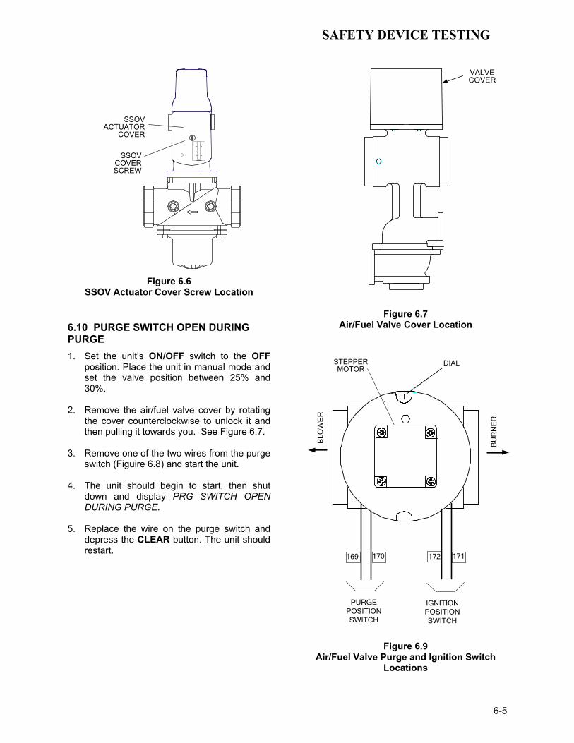
SAFETY DEVICE TESTING
6-5
SSOVACTUATOR
COVER
SSOVCOVERSCREW
Figure 6.6
SSOV Actuator Cover Screw Location
6.10 PURGE SWITCH OPEN DURING PURGE 1. Set the unit’s ON/OFF switch to the OFF
position. Place the unit in manual mode and set the valve position between 25% and 30%.
2. Remove the air/fuel valve cover by rotating
the cover counterclockwise to unlock it and then pulling it towards you. See Figure 6.7.
3. Remove one of the two wires from the purge
switch (Figuire 6.8) and start the unit. 4. The unit should begin to start, then shut
down and display PRG SWITCH OPEN DURING PURGE.
5. Replace the wire on the purge switch and
depress the CLEAR button. The unit should restart.
VALVECOVER
Figure 6.7 Air/Fuel Valve Cover Location
IGNITIONPOSITIONSWITCH
PURGEPOSITIONSWITCH
169 170 172 171
STEPPERMOTOR
DIAL
BLO
WE
R
BU
RN
ER
Figure 6.9 Air/Fuel Valve Purge and Ignition Switch
Locations

SAFETY DEVICE TESTING
6-6
6.11 IGNITION SWITCH OPEN DURING IGNITION 1. Set the unit’s ON/OFF switch to the OFF
position. Place the unit in manual mode and set the valve position between 25% and 30%.
2. Remove the air/fuel valve cover (Fig. 6.7) by
rotating the cover counterclockwise to unlock it then pulling it towards you.
3. Remove one of the two wires from the
ignition switch (Fig. 6.8) and start the unit. 4. The unit should begin to start then shut
down and display IGN SWITCH OPEN DURING IGNITION.
5. Replace the wire on the ignition switch and
depress the CLEAR button. The unit should restart.
6.12 SAFETY PRESSURE RELIEF VALVE TEST Test the safety Pressure Relief Valve in accor-dance with ASME Boiler and Pressure Vessel Code, Section VI.


MAINTENANCE
7-1
SECTION 7 - MAINTENANCE
7.1 MAINTENANCE SCHEDULE The unit requires regular routine maintenance to keep up efficiency and reliability. For best operation and life of the unit, the routine maintenance procedures listed in Table 1 should be performed within the specified time periods. Appendix K contains recommended spare parts lists for maintenance of the KC1000 Boiler.
Table 1 Maintenance Schedule
Para
Item
6 Mos.
12 Mos.
24 Mos.
Labor Time
7.2 Spark Igniter
(124570)
Inspect Replace 20 mins.
7.3 Flame Detector
(G124837)
Inspect Replace 20 mins.
7.4 Combustion Cal.
Check Check 1 hr.
7.5 Testing of Safety
Devices
Test 20 mins.
7.6 *Manifold & Tubes
Inspect & clean
if needed
4 hrs.
7.7 Water Side Inspection
Inspect 2 hr.
7.8 Condensate Drain
Inspect & clean
30 mins.
* Recommended only when unit will be run in an extreme condensing mode for prolonged periods of time.
WARNING! TO AVOID PERSONAL INJURY, BEFORE SERVICING: (A) DISCONNECT AC POWER FROM THE UNIT. (B) SHUT OFF THE GAS SUPPLY TO THE UNIT. (C) ALLOW THE UNIT TO COOL TO A SAFE TEMPERATURE. 7.2 SPARK IGNITER The spark igniter assembly (124570) is located in the body of the burner (Figure 7.1). The igniter may be HOT. Care should be exercised. It is easier to remove the igniter from the unit after the unit has cooled to room temperature. To inspect or replace the Igniter (124570):
1. Set the ON/OFF switch on the control panel to the OFF position and disconnect AC power from the unit.
2. To access the spark igniter, remove the unit’s left side paneland left rear cover.
3. Disconnect the igniter cable from the igniter
contact. 4. Using a 15/16” open-end wrench, remove
the igniter from the burner shell. 5. Inspect the igniter for erosion or carbon
build-up. If there is substantial erosion of the spark gap or ground electrode, the igniter should be replaced. If carbon build-up is present, clean the igniter using fine emery cloth. Repeated carbon build-up on the igniter is an indication that a check of the combustion settings is required. See Section 4 for Combustion Calibration procedures.
6. Prior to reinstalling the igniter, a conductive
anti-seize compound must be applied to the igniter threads.
7. Reinstall the igniter in the burner shell. Do
Not over-tighten. A slight snugging up is sufficient.
8. Reconnect the igniter cable. 9. Replace the left side panel and left rear
cover on the unit.
FLAMEDETECTOR
PROBE
LOWERBURNER
SHELL
BURNERHEAD
BURNERPLATE
IGNITER(124570)
FLAME DETECTOR(124837)
STAGEDIGNITIONORIFICE
Figure 7.1
Spark Igniter and Flame Detector Location
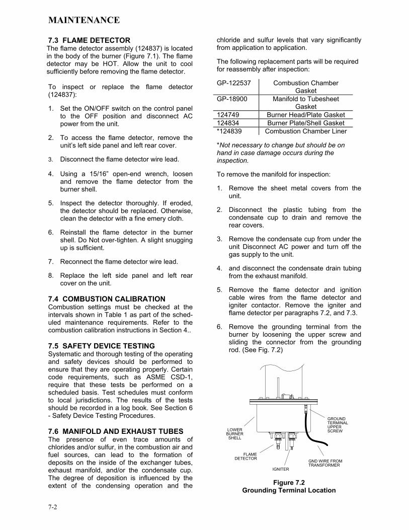
MAINTENANCE
7-2
7.3 FLAME DETECTOR The flame detector assembly (124837) is located in the body of the burner (Figure 7.1). The flame detector may be HOT. Allow the unit to cool sufficiently before removing the flame detector. To inspect or replace the flame detector (124837): 1. Set the ON/OFF switch on the control panel
to the OFF position and disconnect AC power from the unit.
2. To access the flame detector, remove the
unit’s left side panel and left rear cover. 3. Disconnect the flame detector wire lead. 4. Using a 15/16” open-end wrench, loosen
and remove the flame detector from the burner shell.
5. Inspect the detector thoroughly. If eroded,
the detector should be replaced. Otherwise, clean the detector with a fine emery cloth.
6. Reinstall the flame detector in the burner
shell. Do Not over-tighten. A slight snugging up is sufficient.
7. Reconnect the flame detector wire lead. 8. Replace the left side panel and left rear
cover on the unit. 7.4 COMBUSTION CALIBRATION Combustion settings must be checked at the intervals shown in Table 1 as part of the sched-uled maintenance requirements. Refer to the combustion calibration instructions in Section 4.. 7.5 SAFETY DEVICE TESTING Systematic and thorough testing of the operating and safety devices should be performed to ensure that they are operating properly. Certain code requirements, such as ASME CSD-1, require that these tests be performed on a scheduled basis. Test schedules must conform to local jurisdictions. The results of the tests should be recorded in a log book. See Section 6 - Safety Device Testing Procedures. 7.6 MANIFOLD AND EXHAUST TUBES The presence of even trace amounts of chlorides and/or sulfur, in the combustion air and fuel sources, can lead to the formation of deposits on the inside of the exchanger tubes, exhaust manifold, and/or the condensate cup. The degree of deposition is influenced by the extent of the condensing operation and the
chloride and sulfur levels that vary significantly from application to application. The following replacement parts will be required for reassembly after inspection: GP-122537 Combustion Chamber
Gasket GP-18900 Manifold to Tubesheet
Gasket 124749 Burner Head/Plate Gasket 124834 Burner Plate/Shell Gasket *124839 Combustion Chamber Liner *Not necessary to change but should be on hand in case damage occurs during the inspection. To remove the manifold for inspection: 1. Remove the sheet metal covers from the
unit. 2. Disconnect the plastic tubing from the
condensate cup to drain and remove the rear covers.
3. Remove the condensate cup from under the
unit Disconnect AC power and turn off the gas supply to the unit.
4. and disconnect the condensate drain tubing
from the exhaust manifold. 5. Remove the flame detector and ignition
cable wires from the flame detector and igniter contactor. Remove the igniter and flame detector per paragraphs 7.2, and 7.3.
6. Remove the grounding terminal from the
burner by loosening the upper screw and sliding the connector from the grounding rod. (See Fig. 7.2)
GROUNDTERMINALUPPER SCREWLOWER
BURNERSHELL
FLAMEDETECTOR
IGNITER
GND WIRE FROMTRANSFORMER
Figure 7.2
Grounding Terminal Location
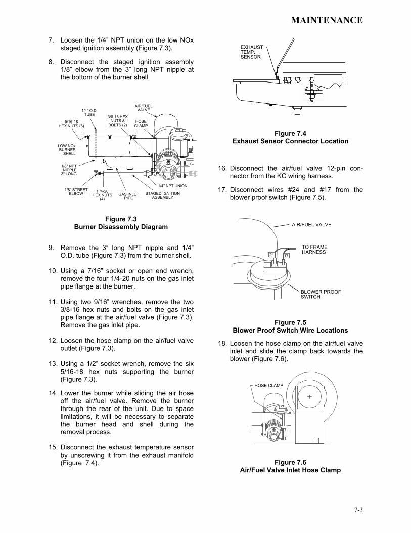
MAINTENANCE
7-3
7. Loosen the 1/4” NPT union on the low NOx staged ignition assembly (Figure 7.3).
8. Disconnect the staged ignition assembly
1/8” elbow from the 3” long NPT nipple at the bottom of the burner shell.
LOW NOxBURNER
SHELL
STAGED IGNITIONASSEMBLY
1/8" STREET ELBOW
1/8" NPT NIPPLE
3" LONG
1 /4-20HEX NUTS
(4)GAS INLET
PIPE
HOSECLAMP
AIR/FUELVALVE
5/16-18HEX NUTS (6)
3/8-16 HEX NUTS &
BOLTS (2)
1/4" NPT UNION
1/4" O.D.TUBE
Figure 7.3 Burner Disassembly Diagram
9. Remove the 3” long NPT nipple and 1/4”
O.D. tube (Figure 7.3) from the burner shell. 10. Using a 7/16” socket or open end wrench,
remove the four 1/4-20 nuts on the gas inlet pipe flange at the burner.
11. Using two 9/16” wrenches, remove the two
3/8-16 hex nuts and bolts on the gas inlet pipe flange at the air/fuel valve (Figure 7.3). Remove the gas inlet pipe.
12. Loosen the hose clamp on the air/fuel valve
outlet (Figure 7.3). 13. Using a 1/2” socket wrench, remove the six
5/16-18 hex nuts supporting the burner (Figure 7.3).
14. Lower the burner while sliding the air hose
off the air/fuel valve. Remove the burner through the rear of the unit. Due to space limitations, it will be necessary to separate the burner head and shell during the removal process.
15. Disconnect the exhaust temperature sensor
by unscrewing it from the exhaust manifold (Figure 7.4).
EXHAUSTTEMP.SENSOR
Figure 7.4 Exhaust Sensor Connector Location
16. Disconnect the air/fuel valve 12-pin con-
nector from the KC wiring harness. 17. Disconnect wires #24 and #17 from the
blower proof switch (Figure 7.5).
AIR/FUEL VALVE
BLOWER PROOFSWITCH
TO FRAMEHARNESS
Figure 7.5 Blower Proof Switch Wire Locations
18. Loosen the hose clamp on the air/fuel valve inlet and slide the clamp back towards the blower (Figure 7.6).
HOSE CLAMP
Figure 7.6
Air/Fuel Valve Inlet Hose Clamp

MAINTENANCE
7-4
19. Using an 11/16” wrench, loosen the compression fittings on the feedback tube between the air/fuel valve and the differential pressure regulator. Remove the feedback tube (Figure 7.7).
20. Using two 9/16” wrenches, remove the two
3/8-16 hex nuts and bolts securing the air/fuel valve to the differential pressure regulator (Figure 7.7).
21. Remove the air/fuel valve, taking care not to
damage the flange “O”- ring.
AIR/FUELVALVE
COMPRESSIONFITTINGS
DIFFERENTIAL PRESS.REGULATOR
3/8 - 16HEX NUT/BOLT
Figure 7.7
Feedback Tube and Air/Fuel Valve to Differential Regulator Bolts
22. Remove the flue venting from the exhaust
manifold. 23. To prevent damage and simplify handling of
the exhaust manifold, it will be necessary to remove the exhaust manifold insulation. Using a 7/16” wrench or socket, remove the 3 bolts and fender washers securing the insulation to the exhaust manifold (Figure 7.8).
24. Loosen the three 1-1/16” nuts that hold the
manifold. Remove the two side nuts. DO NOT REMOVE THE FRONT NUT (Figure 7.8).
25. Carefully pull the manifold down and back,
removing it through the back of the unit. 26. Inspect the manifold and exhaust tubes for
debris. Clean out any debris as necessary. 27. Inspect the combustion chamber and liner.
Replace the liner if any signs of cracking or warping are observed.
NOTE:
The combustion chamber liner should be installed prior to reinstalling the exhaust manifold
SIDE NUT(1 EACH SIDE)
FRONT NUT(DO NOT REMOVE)
EXHAUSTMANIFOLD
INSULATION
7/16" HEX HEAD& FENDER WASHER
(3 PLACES)
Figure 7.8 Manifold Nut and Bolt Locations
28. Replace the gasket between the manifold
and the combustion chamber (Part Number GP-122537). The use of Permatex or a similar gasket adhesive is recommended. Replace the gasket between the manifold and tubesheet (Part No. GP-18900). Do not use any gasket adhesive; this gasket has an adhesive backing.
29. Beginning with the manifold, reinstall all the
components in the reverse order that they were removed.
7.7 HEAT EXCHANGER WATER SIDE INSPECTION
Per CSD-1, the water side of the heat exchanger requires an inspection. To inspect the heat exchanger, proceed as follows: 1. Shut off AC power to the unit. 2. Close the supply and return valves to the
unit (Figure 7.9). 3. Open the drain valve and allow the unit to
fully drain. The 1/4 inch plug in the top of the shell may be removed to aid in drainage or the relief valve may be opened (Figure 7.9).

MAINTENANCE
7-5
RELIEF VALVE
DRAIN VALVE
REDUCING
1/4" PLUG
HOT WATER
HOT WATER
SUPPLY (OUTLET)
RETURN (INLET)
BUSHING
REDUCINGBUSHING
Figure 7.9
Heat Exchanger Supply and Return Locations
4. Remove the 2 ½ inch plug located in the
shell at the rear of the unit (Figure 7.10). 5. Remove the relief valve, drain valve (Figure
7.9) and any reducing bushings. 6. Perform the inspection. Reassemble the unit
once the inspection is completed. 7. Open the supply and return valves and
reconnect AC power to the unit.
2-1 /2 INCHPLUG
Figure 7.10
Heat Exchanger 2 ½ Inch Inspection Plug Location
7.8 Condensate Drain Assembly KC Boilers contain a condensate drain cup (Figure 2.6) which should be inspected and cleaned annually to ensure proper operation. To inspect and clean the assembly, proceed as follows: 1. Remove the left side panel and left rear
cover to provide access to the condensate drain components (see Figure 2.6).
2. Disconnect the plastic tubing from the
condensate cup drain tube to the drain. 3. Remove the condensate cup from the unit.
Thoroughly clean the cup and inspect the cup drain tube for blockage.
4. After the above items have been cleaned
and inspected, reassemble the drain components by reversing the previous steps.


TROUBLESHOOTING
8-1
Chapter 8- TROUBLESHOOTING GUIDE 8.1 INTRODUCTION This troubleshooting guide is intended to aid service/maintenance personnel in isolating the cause of a fault in a KC1000 Boiler. The trouble-shooting procedures contained herein are presented in tabular form on the following pages. These tables are comprised of three columns labeled: Fault Indication, Probable Cause and Corrective Action. The numbered items in the Probable Cause and Corrective Action columns correspond to each other. For example, Probable Cause No. 1 corresponds to Corrective Action No. 1, etc. When a fault occurs in the KC1000 Boiler, proceed as follows to isolate and correct the fault: 1. Observe the fault messages displayed in the
Control Box display.
2. Refer to the Fault Indication column in the following troubleshooting tables and locate the Fault that best describes the existing conditions.
3. Proceed to the Probable Cause column and
start with the first item (1) listed for the Fault Indication.
4. Perform the checks and procedures listed in
the Corrective Action column for the first Probable Cause candidate.
5. Continue checking each additional Probable
Cause for the existing fault until the fault is corrected.
6. If the fault cannot be corrected using the
information provided in the Troubleshooting Tables, please contact your local AERCO Representative.

TROUBLESHOOTING
8-2
TABLE 8-1. BOILER TROUBLESHOOTING
FAULT INDICATION PROBABLE CAUSES CORRECTIVE ACTION AIRFLOW FAULT
DURING IGNITION 1. Blower stopped running due to thermal
or current overload 2. Blocked Blower inlet or inlet ductwork
3. Blocked airflow switch
4. Defective airflow switch
1. Check combustion blower for signs of excessive heat or high current drain that may trip thermal or current overload devices.
2. Inspect the inlet to the combustion blower including any ductwork leading up to the combustion blower for signs of blockage.
3. Remove the airflow switch and inspect for signs of blockage, clean or replace as necessary.
4. Measure the airflow switch for continuity with the combustion blower running. If there is an erratic resistance reading or the resistance reading is greater than zero ohms, replace the switch.
AIRFLOW FAULT DURING PURGE
1. Blower not running or running too slow
2. Defective Air Flow Switch
3. Blocked Air flow Switch
4. Blocked Blower inlet or inlet ductwork.
5. No voltage to switch from control box.
1. Start the unit. If the blower does not run check the blower solid state relay for input and output voltage. If the relay is okay, check the blower.
2. Start the unit. If the blower runs, check the airflow switch for continuity. Replace the switch if there is no continuity.
3. Remove the air flow switch and inspect for signs of blockage, clean or replace as necessary.
4. Inspect the inlet to the combustion blower including any ductwork leading up to the combustion blower for signs of blockage.
5. Measure for 24 VAC during start sequence from each side of the switch to ground. If 24VAC is not present refer to qualified service personnel.
AIRFLOW FAULT DURING RUN
1. Blower stopped running due to thermal or current overload
2. Blocked Blower inlet or inlet ductwork
3. Blocked airflow switch
4. Defective airflow switch
5. Combustion oscillations
1. Check combustion blower for signs of excessive heat or high current draw that may trip thermal or current overload devices.
2. Inspect the inlet to the combustion blower including any ductwork leading up to the combustion blower for signs of blockage.
3. Remove the airflow switch and inspect for signs of blockage, clean or replace as necessary.
4. Measure the airflow switch for continuity with the combustion blower running. If there is an erratic resistance reading or the resistance reading is greater than zero ohms, replace the switch.
5. Run unit to full fire. If the unit rumbles or runs rough, perform combustion calibration.

TROUBLESHOOTING
8-3
TABLE 8-1. BOILER TROUBLESHOOTING – Continued
FAULT INDICATION PROBABLE CAUSES CORRECTIVE ACTION DELAYED
INTERLOCK OPEN 1. Delayed Interlock Jumper not
installed or removed. 2. Device proving switch hooked to
interlocks is not closed
1. Check for a jumper properly installed across the delayed interlock terminals in the I/O box.
2. If there are 2 external wires on these terminals, check to see if an end switch for a device (i.e. a pump, louver, etc.) is tied to these interlocks. Ensure that the device and its end switch are functional. (jumper may be temporarily installed to test interlock
DIRECT DRIVE SIGNAL FAULT
1. Direct drive signal is not present: Not yet installed. Wrong polarity. Signal defective at source. Broken or loose wiring.
2. Signal is not isolated (floating). 3. Control Box signal type selection
switches not set for correct signal type (voltage or current).
1. Check I/O Box to ensure signal is hooked up. Hook up if not installed. If installed, check polarity. Measure signal level. Check continuity of wiring between source and boiler.
2. Check signal at source to ensure it is isolated. 3. Check DIP switch on PMC board to ensure it is set correctly for
the type of signal being sent. Check control signal type set in Configuration Menu.
FLAME LOSS DURING IGN
1. Burner Ground Screw not installed or loose.
2. Worn flame detector
3. No spark from Spark Plug
4. Defective Ignition Transformer
5. Defective Ignition/Stepper (IGST) Board
6. Defective SSOV
7. Defective Differential Pressure Regulator.
8. Carbon or other debris on Burner.
1. Inspect and install/retighten Burner Ground Screw.
2. Remove and inspect the flame detector for signs of wear. Replace if necessary.
3. Close the internal gas valve in the boiler. Install and arc a spark ignitor outside the unit.
4. If there is no spark, check for 120VAC at the primary side to the ignition transformer during the ignition cycle.
5. If 120VAC is not present, the IGST Board in the Control Box may be defective. Refer fault to qualified service personnel.
6. While externally arcing the spark ignitor, observe the open/close indicator in the Safety Shut-Off Valve to ensure it is opening. If the valve does not open, check for 120VAC at the valves input terminals. If 120VAC is not present, the IGST board in the Control Box may be defective. Refer fault to qualified service personnel.
7. Check gas pressure using gauge or manometer into and out of the Air/Fuel Valve to ensure gas is getting to burner.
8. Remove burner and inspect for any carbon or debris. Clean and reinstall

TROUBLESHOOTING
8-4
TABLE 8-1. BOILER TROUBLESHOOTING – Continued
FAULT INDICATION PROBABLE CAUSES CORRECTIVE ACTION FLAME LOSS DURING RUN
1. Worn Flame Detector or cracked ceramic.
2. Defective Differential Regulator.
3. Poor combustion calibration. 4. Debris on burner.
5. Blocked condensate drain.
1. Remove and inspect the Flame Detector for signs of wear or cracked ceramic. Replace if necessary.
2. Check gas pressure readings using a gauge or manometer into and out of the Air/Fuel Valve to ensure that the gas pressure into and out of the valve is correct.
3. Check combustion calibration. Adjust as necessary. 4. Remove the burner and inspect for any carbon or debris. Clean
and reinstall. 5. Remove blockage in condensate drain.
HEAT DEMAND FAILURE
1. The Heat Demand Relays on the Ignition/Stepper board failed to activate when commanded
2. Relay is activated when not in Demand
1. Press CLEAR button and restart the unit. If the fault persists, replace Ignition/Stepper (IGST) Board.
2. Defective relay. Replace IGST Board.
HIGH EXHAUST TEMPERATURE
1. Defective exhaust sensor.
2. Carboned heat exchanger due to incorrect combustion calibration
1. Measure the actual exhaust temperature and continuity of the exhaust sensor. If the exhaust temperature is less than 475 o F and the exhaust sensor shows continuity replace the sensor.
2. If exhaust temperature is greater than 500 o F, check combustion calibration. Calibrate or repair as necessary.
HIGH GAS PRESSURE
1. Incorrect supply gas pressure.
2. Defective Supply Regulator or Wrong Style Regulator
3. Defective High Gas Pressure Switch
1. If using a non-lock up style regulator for the gas supply, measure static gas pressure downstream, it should be 14”WC or less. Adjust as necessary.
2. If gas supply pressure cannot be lowered, a lock-up style regulator may be required or the supply regulator may be defective.
3. Remove the leads from the high gas pressure switch. Measure continuity across the common and normally closed terminals with the unit not firing. Replace the switch if it does not show continuity.

TROUBLESHOOTING
8-5
TABLE 8-1. BOILER TROUBLESHOOTING – Continued
FAULT INDICATION PROBABLE CAUSES CORRECTIVE ACTION HIGH WATER TEMP
SWITCH OPEN 1. Faulty Water temperature switch.
2. Incorrect PID settings.
3. Faulty shell temperature sensor.
4. Unit in Manual mode 5. Unit setpoint is greater than Over
Temperature Switch setpoint.
6. Boiler Management System PID or other settings not correctly setup.
7. No interlock to boiler or BMS to disable boiler(s) in event that system pumps have failed.
8. System flow rate changes are occurring faster than boilers can respond.
1. Test the temperature switch to insure it trips at its actual water temperature setting.
2. Check PID settings against Menu Default settings in the Appendix. If the settings have been changed, record the current readings then reset them to the default values.
3. Using the resistance charts in the Appendix C, Measure the resistance of Shell sensor and BTU sensor at a known water temperature.
4. If unit is in Manual Mode switch to Auto Mode. 5. Check setpoint of unit and setpoint of Temperature Switch;
Ensure that the temperature switch is set higher than the unit’s setpoint.
6. Check the BMS for changes to PID default values, correct as necessary.
7. If system pump is controlled by Energy Management System other than BMS or pumps are individually controlled by boiler, check to see if there are flow switches interlocked to the BMS or boiler.
8. If the system is a variable flow system, monitor system flow changes to ensure that the rate of flow change is not faster than what the boilers can respond to.
HIGH WATER TEMPERATURE
1. See HIGH WATER TEMPERATURE SWITCH OPEN.
2. Temp HI Limit setting is too low.
1. See HIGH WATER TEMPERATURE SWITCH OPEN.
2. Check Temp HI Limit setting. IGN BOARD
COMM FAULT 1. Communication fault has occurred
between the PMC board and Ignition/Stepper (IGST) board
1. Press CLEAR button and restart unit. If fault persists, contact qualified Service Personnel.

TROUBLESHOOTING
8-6
TABLE 8-1. BOILER TROUBLESHOOTING – Continued
FAULT INDICATION PROBABLE CAUSES CORRECTIVE ACTION IGN SWTCH CLOSED
DURING PURGE
1. Air/Fuel Valve not rotating
2. Defective or shorted switch
3. Switch wired incorrectly
4. Defective Power Supply Board or fuse
5. Defective IGST Board
1. Start the unit. The Air/Fuel Valve should rotate to the purge (open) position. If the valve does not rotate at all or does not rotate fully open, check the Air/Fuel Valve calibration. If calibration is okay, the problem may be in the Air-Fuel Valve or the Control Box. Refer to qualified service personnel
2. . If the Air/Fuel Valve does rotate to purge, check the ignition switch for continuity between the N.O. and COM terminals. If the switch shows continuity when not in contact with the cam replace the switch.
3. Check to ensure that the switch is wired correctly (correct wire numbers on the normally open terminals). If the switch is wired correctly, replace the switch
4. Check DS1 & DS2 LEDs on Power Supply Board. If they are not steady ON, replace Power Supply Board.
5. Check “Heartbeat” LED DS1 and verify it is blinking ON & OFF every second. If not, replace IGST Board
IGN SWTCH OPEN DURING IGNITION
1. Air/Fuel Valve not rotating to ignition position.
2. Defective ignition switch
3. Defective Power Supply Board or fuse
4. Defective IGST Board
1. Start the unit. The Air/Fuel Valve should rotate to the purge (open) position, then back to ignition position (towards closed) during the ignition cycle. If the valve does not rotate back to the ignition position, check the Air/Fuel Valve calibration. If calibration is okay, the problem may be in the Air/Fuel Valve or the Control Box. Refer fault to qualified service personnel.
2. If the Air/Fuel Valve does rotate to the ignition position, check the ignition position switch for continuity between the N.O. and COM terminals when in contact with the cam.
3. Check DS1 & DS2 LEDs on Power Supply Board. If they are not steady ON, replace Power Supply Board.
4. Check “Heartbeat” LED DS1 and verify it is blinking ON & OFF every second. If not, replace IGST Board.
INTERLOCK OPEN
1. Interlock jumper not installed or removed
2. Energy Management System does not have boiler enabled.
3. Device proving switch hooked to interlocks is not closed.
1. Check for a jumper properly installed across the interlock terminals in the I/O box
2. If there are two external wires on these terminals check any Energy Management system to see if they have the units disabled (a jumper may be temporarily installed to see if the interlock circuit is functioning).
3. Check that proving switch for any device hooked to the interlock circuit is closing and that the device is operational.

TROUBLESHOOTING
8-7
TABLE 8-1. BOILER TROUBLESHOOTING – Continued
FAULT INDICATION PROBABLE CAUSES CORRECTIVE ACTION LINE VOLTAGE OUT OF PHASE
1. Line and Neutral switched in AC Power Box.
2. Incorrect power supply transformer wiring.
1. Check hot and neutral in AC Power Box to ensure they are not reversed
2. Check transformer wiring, in AC Power Box, against the power box transformer wiring diagram to ensure it is wired correctly
LOW GAS PRESSURE
1. Incorrect supply gas pressure.
2. Defective or incorrectly sized Gas Supply Regulator.
3. Defective Low Pressure Gas Switch
1. Measure gas pressure upstream of the supply gas regulator with the unit firing ensure it is 14” WC or greater.
2. Measure gas pressure downstream of the supply regulator with unit firing and adjust the gas supply regulator to increase the outlet gas pressure; if outlet gas pressure cannot be increased, check the sizing of the Supply regulator.
3. Measure gas pressure at the low gas pressure switch, if it is greater than 5” WC, measure continuity across the switch and replace if necessary.
LOW WATER LEVEL
1. Insufficient water level in system 2. Defective water level circuitry.
3. Defective water level probe.
1. Check system for sufficient water level. 2. Test water level circuitry using the Control Box front panel LOW
WATER TEST and RESET buttons. Replace water level circuitry if it does not respond.
3. Check continuity of probe end to the shell, change probe if there is no continuity.
MODBUS COMM FAULT
1. Boiler not seeing information from Modbus network
1. Check network connections. If fault persists, contact qualified Service Personnel.
PRG SWTCH CLOSED DURING IGNITION
1. A/F Valve rotated open to purge and did not rotate to ignition position
2. Defective or shorted switch.
3. Switch wired incorrectly. 4. Defective Power Supply Board or
fuse
1. Start the unit. The Air/Fuel Valve should rotate to the purge (open) position, then back to ignition position (towards closed) during the ignition cycle. If the valve does not rotate back to the ignition position, check the Air/Fuel Valve calibration. If calibration is okay, the problem may be in the Air/Fuel Valve or the Control Box. Refer fault to qualified service personnel.
2. If the Air/Fuel Valve does rotate to the ignition position, check the purge switch for continuity between the N.O. and COM terminals. If the switch shows continuity when not in contact with the cam, check to ensure that the switch is wired correctly (correct wire numbers on the normally open terminals).
3. If the switch is wired correctly, replace the switch. 4. Check DS1 & DS2 LEDs on Power Supply Board. If they are not
steady ON, replace Power Supply Board.

TROUBLESHOOTING
8-8
TABLE 8-1. BOILER TROUBLESHOOTING – Continued
FAULT INDICATION PROBABLE CAUSES CORRECTIVE ACTION continued 5. Defective IGST Board 5. Check “Heartbeat” LED DS1 and verify it is blinking ON & OFF
every second. If not, replace IGST Board. PRG SWTCH OPEN
DURING PURGE 1. Defective purge switch.
2. No voltage present at switch.
3. Switch wired incorrectly.
4. Defective Power Supply Board or fuse
5. Defective IGST Board
1. If the air-fuel valve does rotate, check the purge switch for continuity when closing. Replace switch if continuity does not exist.
2. Measure for 24 VAC from each side of the switch to ground. If 24VAC is not present, refer fault to qualified service personnel.
3. Check to ensure that the switch is wired correctly (correct wire numbers on the normally open terminals).
4. Check DS1 & DS2 LEDs on Power Supply Board. If they are not steady ON, replace Power Supply Board.
5. Check “Heartbeat” LED DS1 and verify it is blinking ON & OFF every second. If not, replace IGST Board.
OUTDOOR TEMP SENSOR FAULT
1. Loose or broken wiring. 2. Defective Sensor.
3. Incorrect Sensor.
1. Inspect Outdoor Temperature sensor for loose or broken wiring. 2. Check resistance of sensor to determine if it is within
specification. 3. Ensure that the correct sensor is installed.
REMOTE SETPT SIGNAL FAULT
1. Remote setpoint signal not present: Not yet installed. Wrong polarity. Signal defective at source. Broken or loose wiring.
2. Signal is not isolated (floating) if 4 to 20 mA.
3. Control Box signal type selection switches not set for correct signal type (voltage or current).
1. Check I/O Box to ensure signal is hooked up. Hook up if not installed. If installed, check polarity. Measure signal level. Check continuity of wiring between source and boiler.
2. Check signal at source to ensure it is isolated.
3. Check DIP switch on PMC board to ensure it is set correctly for the type of signal being sent. Check control signal type set in Configuration Menu.
RESIDUAL FLAME
1. SSOV not fully closed.
2. Defective Flame Detector
1. Check open/close indicator window of Safety Shut-Off Valve (SSOV) and ensure that the SSOV is fully closed. If not fully closed, replace the valve and or actuator. Close gas shut-off valve downstream of SSOV. Install a manometer or gauge in a gas test port between the SSOV and the gas shut off valve. If a gas pressure reading is observed replace the SSOV valve and or actuator.
2. Replace Flame Detector.

TROUBLESHOOTING
8-9
TABLE 8-1. BOILER TROUBLESHOOTING – Continued
FAULT INDICATION PROBABLE CAUSES CORRECTIVE ACTION SSOV FAULT
DURING PURGE See SSOV SWITCH OPEN
SSOV FAULT DURING RUN
1. SSOV switch closed for 15 seconds during run.
1. Replace SSOV actuator.
SSOV RELAY FAILURE
1. SSOV relay failed on board. 1. Ensure that Neutral and Earth Ground are connected at the source and there is no voltage measured between them. Measurement should indicate near zero or no more than a few millivolts.
2. Check the SSOV power wiring. 3. Press CLEAR button and restart unit. If fault persists, replace
Ignition/Stepper (IGST) Board. SSOV
SWITCH OPEN 1. Actuator not allowing for full closure
of gas valve
2. SSOV powered when it should not be
3. Defective Switch or Actuator
4. Incorrectly wired switch.
1. Observe operation of the Safety Shut-Off Valve (SSOV) through indicator on the Valve actuator and ensure that the valve is fully and not partially closing.
2. If the SSOV never closes, it may be powered continuously. Close the gas supply and remove power from the unit. Refer fault to qualified service personnel.
3. Remove the electrical cover from the SSOV and check switch continuity. If the switch does not show continuity with the gas valve closed, either adjust or replace the switch or actuator.
4. Ensure that the SSOV Proof of Closure switch is correctly wired.
STEPPER MOTOR FAILURE
1. Air/Fuel Valve out of calibration.
2. Air/Fuel Valve unplugged. 3. Loose wiring connection to the
stepper motor. 4. Defective Air/Fuel Valve stepper
motor. 5. Defective Power Supply Board or
fuse 6. Defective IGST Board
1. Refer to GF-112 and perform Stepper Test (para. 6.3.5) to ensure stepper motor rotates properly between the 0% (fully closed) and 100% (fully open) positions. Verify that the VALVE POSITION bar graph and the dial on the Air/Fuel Valve track each other to indicate proper operation. If operation is not correct, perform the Stepper Feedback Calibration (GF-112, para. 6.2.1).
2. Check that the Air/Fuel Valve is connected to the Control Box. 3. .Inspect for loose connections between the Air/Fuel Valve motor
and the wiring harness. 4. Replace stepper motor. 5. Check DS1 & DS2 LEDs on Power Supply Board. If they are not
steady ON, replace Power Supply Board. 6. Check “Heartbeat” LED DS1 and verify it is blinking ON & OFF
every second. If not, replace IGST Board.

RS232 COMMUNICATION
9-1
Section 9 - RS232 COMMUNICATION
9.1 INTRODUCTION
The RS232 port on the front panel of the C-More Control Box (Figure 3-1) can be interfaced to a laptop computer or other suitable terminal using a RS232 adapter cable. RS232 communication can be accomplished using any “Dumb Terminal” emulation, such as “Hyper Terminal” which is included with Microsoft Windows. The RS232 communication feature permits viewing or changing of Control Panel menu options and also provides access to data logs showing Event Time Line, Fault and Sensor log displays.
9.2 RS232 COMMUNICATION SETUP
Regardless of the terminal emulation utilized, the following guidelines must be adhered to when setting up the RS232 communication link:
1. Baud Rate – The baud rates which can be used with the C-More Control Panel are:
1. 2400
2. 4800
3. 9600 (Default)
4. 19.2K
2. Data Format – The program must be set for: 8 data bits, 1 stop bit, no parity and either Xon/Xoff or No flow control.
9.3 MENU PROCESSING UTILIZING RS232
COMMUNICATION
Viewing data logs and viewing or changing Control Panel menu options using RS232 communication is accomplished as follows:
1. Start the emulator software program and ensure that the specified baud rate and data formats have been entered.
2. Press the Enter key on the laptop. An asterisk (*) prompt should appear.
3. At the prompt, enter the valid RS232 password (jaguar) in lower case letters and press Enter.
4. “Welcome to Aerco” will appear in the laptop or “dumb terminal” display with a listing of the following available entry choices:
M = Display next Menu D = Display menu items N = Display next menu items Cxx = Change item xx F = Fault log display S = Sensor log display T = Time line display L = Log off
NOTE: The Level 1 password (159) must be entered to change options in the Setup, Configuration and Tuning Menus. The Level 2 password (6817) must be entered to view or change options in the Calibration and Diagnostics Menus. With the exception of the password entry, all other keyboard entries can be made using either upper or lower case.
5. To view the available menus in the top-down sequence shown in Figure 3-2, enter M <Rtn>. The Menu title and first 10 options will be displayed.
6. When viewing menus containing more than 10 options, enter N <Rtn> to display the remaining options.
7. Shortcut keys are also available to go directly to a specific menu. These shortcut keys are:
m0 Default (Operating) Menu m1 Setup Menu m2 Configuration Menu m3 Tuning Menu m4 Calibration Menu m5 Diagnostic Menu
8. To change a value or setting for a displayed menu option, proceed as follows:
(a) Enter C, followed by the number to the right of the displayed option to be changed, and then press <Rtn>.
(b) Enter the desired value or setting for the option and press <Rtn>. Refer to Section 3, Tables 3-2 through 3-5 for allowable entry ranges and settings for the Operating, Setup, Configuration and Tuning Menus. (The Calibration and Diagnostic Menus should only be used by Factory-Trained service personnel).
RS232 COMMUNICATION
9-2
(c) Menu changes will be stored in non-volatile memory.
9. To redisplay the menu and view the option which was just changed in step 5, enter D and press <Rtn>.
10. To display the Fault (F) Log, Sensor (S) Log or Time (T) Line Log, press F, S or T followed by <Rtn>. Refer to paragraph 9.4 for descriptions and samples of these data logs.
11. To log off and terminate the RS232 com-munication link, press L followed by <Rtn>.
9.4 DATA LOGGING
During operation, the C-More Control Panel continuously monitors and logs data associated with operational events, faults and sensor readings associated with the boiler or water heater system. Descriptions of these data logs are provided in the following paragraphs. The basic procedure for accessing each data log is described in paragraph 9.3, step 7.
9.4.1 Fault Log The C-More Control Panel logs the last 20 faults (0 – 19) starting with the most recent (#0). They can be viewed in the front panel display or via the RS232 port. The Fault Log cannot be cleared. If the Fault Log already contains 10 faults, the earliest fault is overwritten when a new fault occurs. A sample Fault Log display is shown in Table 9-1.
NOTE: The Operation Time (T) Log can store thousands of records. Therefore, to view the most recently logged record, enter “T” followed by 0 (zero) and press Enter (i.e. T0 <Enter>). To view earlier records in reverse chronological order, enter T and press Enter. To go back 200 or 1000 records, enter T200 or T1000, etc. and press Enter.
9.4.2 Operation Time Log The Operation Time Log consists of a string of ASCII records stored in non-volatile memory
within the C-More Control Panel. Events such as power-up, ignition and turn-off are time stamped. Data logged while the unit is running are run-length encoded. Data is logged or the run-length incremented every 30 seconds. For a new run record to be logged, the fire rate or flame strength must change by more than 5%, or the run mode must change. At steady-state, the run-length is allowed to reach a maximum of 30 minutes before the record is logged. This means that no more than 30 minutes of data can be lost if the unit loses power. Table 9-2 shows a sample Operation Time Log for a boiler:
The Operation Time Log can only be accessed through the RS232 interface using a laptop or other terminal device. Ten operation time records are displayed for each T command entry. The operation time log can be cleared ONLY by factory authorized personnel using the Clear Log option in the Factory menu.
NOTE: The Sensor (S) Log can store up to 1200 records. Therefore, to view the most recently logged record, enter “S” followed by 0 (zero) and then press Enter (i.e. S0 <Enter>). To view earlier records in reverse chronological order, enter S and press Enter. To go back 200 or 700 records, enter S200 or S700, etc. and press Enter.
9.4.3 Sensor Log The sensor values can be logged at a different rate if needed by setting the Sensor Log Interval in the Diagnostics Menu. The log interval can vary from once every minute to once every day. Table 9-3 shows a sample Sensor Log every 5 minutes for a boiler running in Constant Setpoint mode.

RS232 COMMUNICATION
9-3
Table 9-1. Sample Fault Log Display
No. Fault Message Cycle Date Time 0 Direct Drive Signal Fault 609 1/10/02 8:42am 1 Low Gas Pressure 366 7/04/01 5:29pm 2 Loss of Power 0 1/01/01 11:50am
Table 9-2. Sample Operation Time Log Display
Status Fire Rate Flame Run Length Date Time Off, Direct Drive 0 0 8 1/15/02 2:35pm Run, Direct Drive 38 100 34 1/15/02 2:27pm Run, Direct Drive 31 100 30 1/15/02 1:53am Run, Direct Drive 35 100 2 1/15/02 1:23pm Run, Direct Drive 29 100 0 1/15/02 1:21pm Ignition 0 0 0 1/15/02 1:20pm Off, Switch 0 0 35 1/15/02 12:30pm Run, Manual 40 100 0 1/15/02 11:55am Ignition 0 0 0 1/15/02 11:55am Power-up 0 0 0 1/15/02 11:50am
Table 9-3. Sample Sensor Log Display Setpt Outlet Outdr FFWD Aux Inlet Exhst CO O2 Flow Date Time 130 181 OPEN OPEN OPEN OPEN OPEN 0 .0 0 1/15/02 5:51pm 130 180 OPEN OPEN OPEN OPEN OPEN 0 .0 0 1/15/02 5:46pm 130 180 OPEN OPEN OPEN OPEN OPEN 0 .0 0 1/15/02 5:41pm 130 179 OPEN OPEN OPEN OPEN OPEN 0 .0 0 1/15/02 5:36pm 130 180 OPEN OPEN OPEN OPEN OPEN 0 .0 0 1/15/02 5:31pm 130 180 OPEN OPEN OPEN OPEN OPEN 0 .0 0 1/15/02 5:26pm 130 180 OPEN OPEN OPEN OPEN OPEN 0 .0 0 1/15/02 5:21pm 130 180 OPEN OPEN OPEN OPEN OPEN 0 .0 0 1/15/02 5:16pm 130 179 OPEN OPEN OPEN OPEN OPEN 0 .0 0 1/15/02 5:11pm 130 180 OPEN OPEN OPEN OPEN OPEN 0 .0 0 1/15/02 5:06pm

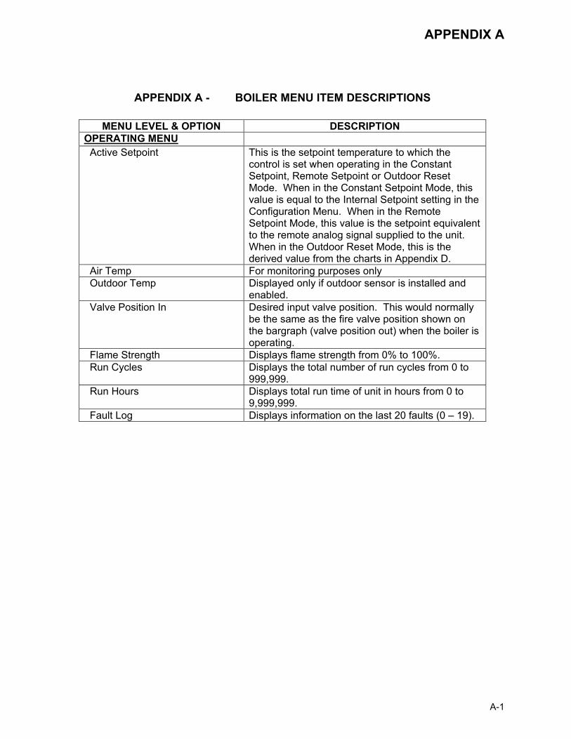
APPENDIX A
A-1
APPENDIX A - BOILER MENU ITEM DESCRIPTIONS
MENU LEVEL & OPTION DESCRIPTION OPERATING MENU Active Setpoint This is the setpoint temperature to which the
control is set when operating in the Constant Setpoint, Remote Setpoint or Outdoor Reset Mode. When in the Constant Setpoint Mode, this value is equal to the Internal Setpoint setting in the Configuration Menu. When in the Remote Setpoint Mode, this value is the setpoint equivalent to the remote analog signal supplied to the unit. When in the Outdoor Reset Mode, this is the derived value from the charts in Appendix D.
Air Temp For monitoring purposes only Outdoor Temp Displayed only if outdoor sensor is installed and
enabled. Valve Position In Desired input valve position. This would normally
be the same as the fire valve position shown on the bargraph (valve position out) when the boiler is operating.
Flame Strength Displays flame strength from 0% to 100%. Run Cycles Displays the total number of run cycles from 0 to
999,999. Run Hours Displays total run time of unit in hours from 0 to
9,999,999. Fault Log Displays information on the last 20 faults (0 – 19).

APPENDIX A
A-2
APPENDIX A - BOILER MENU ITEM DESCRIPTIONS - CONTINUED MENU LEVEL & OPTION DESCRIPTION
SETUP MENU Password Allows password to be entered.
Once the valid password (159) is entered, options in the Setup, Configuration and Tuning Menus can be modified.
Language Permits selection of English, Spanish or French for displayed messages. Default is English.
Time Displays time from 12:00 am to 11:59 pm. Date Displays dates from 01/01/00 to 12/31/99 Unit of Temp Permits selection of temperature displays in degrees
Fahrenheit (°F) or degrees Celsius (°C). Default is °F.
Comm Address For RS-485 communications (0 to 127). Default address is 0. RS-232 should have its own (programmable) password.
Baud Rate Allows communications Baud Rate to be set (2400 to 19.2K). Default is 9600.
Software Version Identifies the current software version of the control box (Ver 0.0 to Ver 9.9).
CONFIGURATION MENU Internal Setpoint Allows internal setpoint to be set . Default is 130°F. Unit Type Allows selection of KC Boiler, KC Boiler LN, BMK
Boiler, BMK Boiler LN, BMK Boiler Dual, KC Water Heater, KC Water Heater LN, Water Heater 2010
Unit Size Sets unit size from 0.5 to 6.0 MBTUs. Default is 1.0 MBTU.
Fuel Type Allows selection of Natural Gas or Propane Boiler Mode It allows selection of: Constant Setpoint, Remote
Setpoint, Direct Drive, Combination, or Outdoor Reset Mode. Default is Constant Setpoint Mode.
Remote Signal Used to set the type of external signal which will be used when operating in the Remote Setpoint, Direct Drive or Combination Mode. The factory default is 4-20 mA/1-5V.
Bldg Ref Temp
Allows the building reference temperature to be set when operating a boiler in the Outdoor Reset Mode. Default is 70°F.
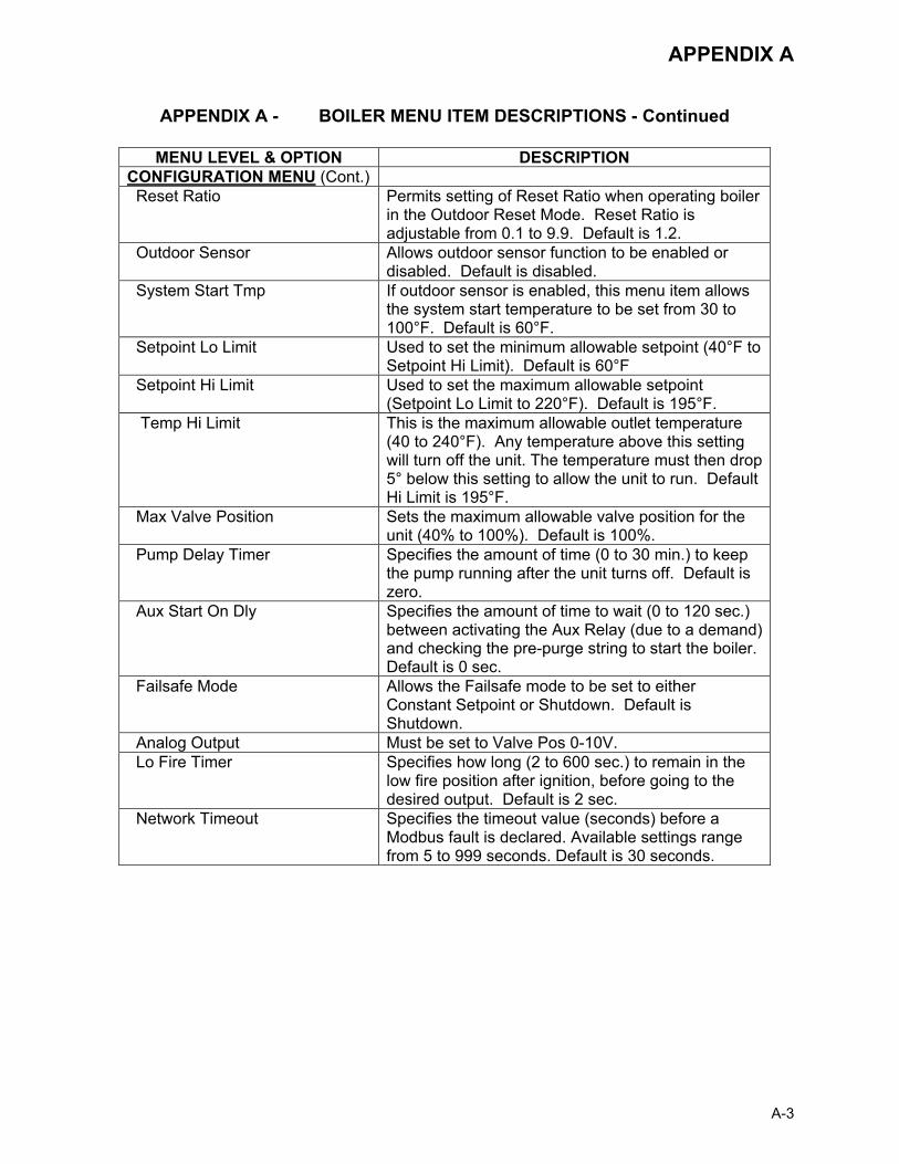
APPENDIX A
A-3
APPENDIX A - BOILER MENU ITEM DESCRIPTIONS - Continued
MENU LEVEL & OPTION DESCRIPTION CONFIGURATION MENU (Cont.) Reset Ratio Permits setting of Reset Ratio when operating boiler
in the Outdoor Reset Mode. Reset Ratio is adjustable from 0.1 to 9.9. Default is 1.2.
Outdoor Sensor Allows outdoor sensor function to be enabled or disabled. Default is disabled.
System Start Tmp If outdoor sensor is enabled, this menu item allows the system start temperature to be set from 30 to 100°F. Default is 60°F.
Setpoint Lo Limit Used to set the minimum allowable setpoint (40°F to Setpoint Hi Limit). Default is 60°F
Setpoint Hi Limit Used to set the maximum allowable setpoint (Setpoint Lo Limit to 220°F). Default is 195°F.
Temp Hi Limit This is the maximum allowable outlet temperature (40 to 240°F). Any temperature above this setting will turn off the unit. The temperature must then drop 5° below this setting to allow the unit to run. Default Hi Limit is 195°F.
Max Valve Position Sets the maximum allowable valve position for the unit (40% to 100%). Default is 100%.
Pump Delay Timer Specifies the amount of time (0 to 30 min.) to keep the pump running after the unit turns off. Default is zero.
Aux Start On Dly Specifies the amount of time to wait (0 to 120 sec.) between activating the Aux Relay (due to a demand) and checking the pre-purge string to start the boiler. Default is 0 sec.
Failsafe Mode Allows the Failsafe mode to be set to either Constant Setpoint or Shutdown. Default is Shutdown.
Analog Output Must be set to Valve Pos 0-10V. Lo Fire Timer Specifies how long (2 to 600 sec.) to remain in the
low fire position after ignition, before going to the desired output. Default is 2 sec.
Network Timeout Specifies the timeout value (seconds) before a Modbus fault is declared. Available settings range from 5 to 999 seconds. Default is 30 seconds.

APPENDIX A
A-4
APPENDIX A - BOILER MENU ITEM DESCRIPTIONS - Continued
MENU LEVEL & OPTION DESCRIPTION CONFIGURATION MENU (Cont.) HI DB Setpt EN Operating at a Valve Position below this value will
inhibit the DEADBAND feature. When operating at a Valve Position below this value, the effective Setpoint is equal to Active Setpoint + DEADBAND HIGH. Setting range is from 0 to 100. (Default is 30)
Demand Offset This entry will reduce excessive ON/OFF cycling in AUTO mode. When this entry is a non-zero value, the unit will not turn on again until Valve Position In reaches the Start Level value AND the Outlet Temperature goes below the Active Setpoint – Demand Offset. In addition, the boiler will fire at the 29% Valve Position level or below for a period of one minute. When this entry is set to zero, the unit will turn on again as soon as the Valve Position in reaches the Start Level value. There will not be a one minute delay when firing at the 29% Valve Position level. Setting range is 0 to 25. (Default is 10)
Deadband High Deadband Low
Deadband High and Deadband Low settings create an “Outlet Temperature” Zone. In which no Valve Position corrections will be attempted. The Deadband ZONE is defined as operating with an Outlet Temperature between Active Setpoint + Deadband High and Active Setpoint – Deadband Low. When the Outlet Temperature reaches Active Setpoint and remains there for a period of 15 seconds, the unit will go into a DEADBAND MODE at which point no Valve Position corrections will be attempted while the Outlet Temperature remains anywhere within the Deadband ZONE. When the unit is in the DEADBAND MODE, the °F or °C LED will flash on and off. When the Outlet Temperature drifts out of the Deadband ZONE, the DEADBAND MODE will be terminated and the PID LOOP will again attempt Valve Position corrections. Setting range is 0 to 25. (Default is 2 for both Deadband High and Deadband Low)
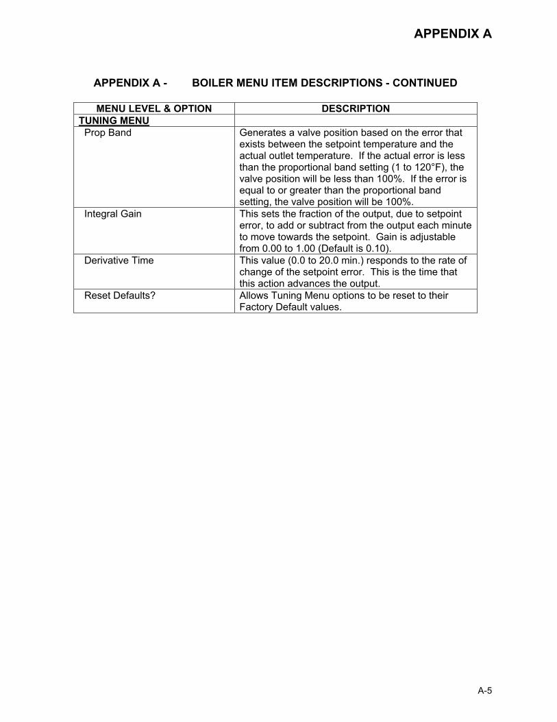
APPENDIX A
A-5
APPENDIX A - BOILER MENU ITEM DESCRIPTIONS - CONTINUED
MENU LEVEL & OPTION DESCRIPTION TUNING MENU Prop Band Generates a valve position based on the error that
exists between the setpoint temperature and the actual outlet temperature. If the actual error is less than the proportional band setting (1 to 120°F), the valve position will be less than 100%. If the error is equal to or greater than the proportional band setting, the valve position will be 100%.
Integral Gain This sets the fraction of the output, due to setpoint error, to add or subtract from the output each minute to move towards the setpoint. Gain is adjustable from 0.00 to 1.00 (Default is 0.10).
Derivative Time This value (0.0 to 20.0 min.) responds to the rate of change of the setpoint error. This is the time that this action advances the output.
Reset Defaults? Allows Tuning Menu options to be reset to their Factory Default values.
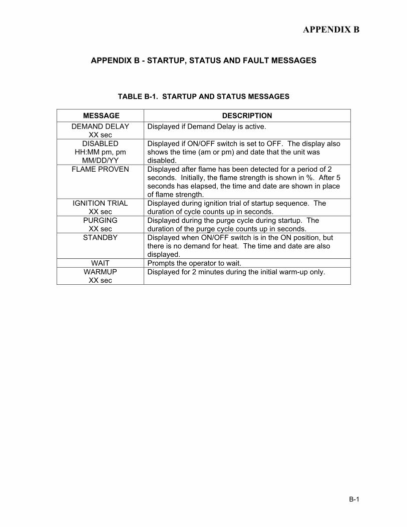
APPENDIX B
B-1
APPENDIX B - STARTUP, STATUS AND FAULT MESSAGES
TABLE B-1. STARTUP AND STATUS MESSAGES
MESSAGE DESCRIPTION DEMAND DELAY
XX sec Displayed if Demand Delay is active.
DISABLED HH:MM pm, pm
MM/DD/YY
Displayed if ON/OFF switch is set to OFF. The display also shows the time (am or pm) and date that the unit was disabled.
FLAME PROVEN
Displayed after flame has been detected for a period of 2 seconds. Initially, the flame strength is shown in %. After 5 seconds has elapsed, the time and date are shown in place of flame strength.
IGNITION TRIAL XX sec
Displayed during ignition trial of startup sequence. The duration of cycle counts up in seconds.
PURGING XX sec
Displayed during the purge cycle during startup. The duration of the purge cycle counts up in seconds.
STANDBY Displayed when ON/OFF switch is in the ON position, but there is no demand for heat. The time and date are also displayed.
WAIT Prompts the operator to wait. WARMUP
XX sec Displayed for 2 minutes during the initial warm-up only.

APPENDIX B
B-2
TABLE B-2. FAULT MESSAGES
FAULT MESSAGE FAULT DESCRIPTION
AIRFLOW FAULT DURING PURGE
The Blower Proof Switch opened during purge, or air inlet is blocked.
AIRFLOW FAULT DURING IGN
The Blower Proof Switch opened during ignition.
AIRFLOW FAULT DURING RUN
The Blower Proof Switch opened during run.
DELAYED INTERLOCK OPEN
The Delayed Interlock is open.
DIRECT DRIVE SIGNAL FAULT
The direct drive signal is not present or is out of range.
FFWD TEMP SENSOR FAULT
The temperature measured by the Feed Forward (FFWD) Sensor is out of range.
FLAME LOSS DURING IGN
The Flame signal was not seen during ignition or lost within 5 seconds after ignition.
FLAME LOSS DURING RUN
The Flame signal was lost during run.
HEAT DEMAND FAILURE
The Heat Demand Relays on the Ignition board failed to activate when commanded.
HIGH EXHAUST TEMPERATURE
The High Exhaust Temperature Limit Switch is closed.
HIGH GAS PRESSURE
The High Gas Pressure Limit Switch is open.
HIGH WATER TEMPERATURE
The temperature measured by the Outlet Sensor exceeded the Temp Hi Limit setting.
HIGH WATER TEMP SWITCH OPEN
The High Water Temperature Limit Switch is open.
IGN BOARD COMM FAULT
A communication fault has occurred between the PMC board and Ignition board.
IGN SWTCH CLOSED DURING PURGE
The Ignition Position Limit switch on the Air/Fuel Valve closed during purge.
IGN SWTCH OPEN DURING IGNITION
The Ignition Position Limit switch on the Air/Fuel Valve opened during ignition.
INTERLOCK OPEN
The Remote Interlock is open.
LINE VOLTAGE OUT OF PHASE
The Line (Hot) and Neutral wires are reversed.
LOW GAS PRESSURE
The Low Gas Pressure Limit Switch is open.
LOW WATER LEVEL
The Low Water Cutoff board is indicating low water level.
NETWORK COMM FAULT
The RS-485 network information is not present or is corrupted.
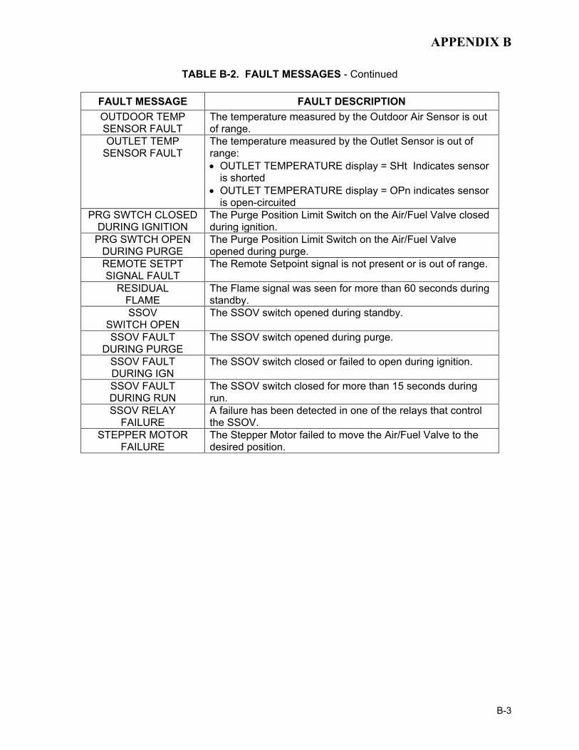
APPENDIX B
B-3
TABLE B-2. FAULT MESSAGES - Continued
FAULT MESSAGE FAULT DESCRIPTION OUTDOOR TEMP SENSOR FAULT
The temperature measured by the Outdoor Air Sensor is out of range.
OUTLET TEMP SENSOR FAULT
The temperature measured by the Outlet Sensor is out of range: • OUTLET TEMPERATURE display = SHt Indicates sensor
is shorted • OUTLET TEMPERATURE display = OPn indicates sensor
is open-circuited PRG SWTCH CLOSED
DURING IGNITION The Purge Position Limit Switch on the Air/Fuel Valve closed during ignition.
PRG SWTCH OPEN DURING PURGE
The Purge Position Limit Switch on the Air/Fuel Valve opened during purge.
REMOTE SETPT SIGNAL FAULT
The Remote Setpoint signal is not present or is out of range.
RESIDUAL FLAME
The Flame signal was seen for more than 60 seconds during standby.
SSOV SWITCH OPEN
The SSOV switch opened during standby.
SSOV FAULT DURING PURGE
The SSOV switch opened during purge.
SSOV FAULT DURING IGN
The SSOV switch closed or failed to open during ignition.
SSOV FAULT DURING RUN
The SSOV switch closed for more than 15 seconds during run.
SSOV RELAY FAILURE
A failure has been detected in one of the relays that control the SSOV.
STEPPER MOTOR FAILURE
The Stepper Motor failed to move the Air/Fuel Valve to the desired position.
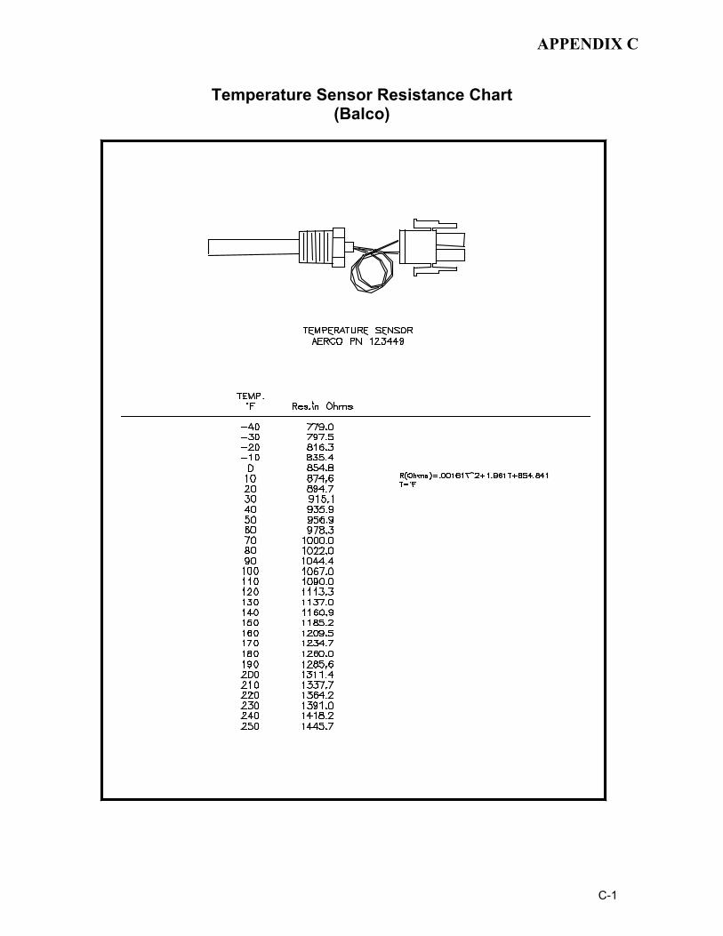
APPENDIX C
C-1
Temperature Sensor Resistance Chart (Balco)

APPENDIX D
D-1
INDOOR/OUTDOOR RESET RATIO CHARTS
Header Temperature for a Building Reference Temperature of 50F
RESET RATIO Air
Temp 0.6 0.8 1.0 1.2 1.4 1.6 1.8 2.0 2.2 2.4
50F 50 50 50 50 50 50 50 50 50 50 45F 53 54 55 56 57 58 59 60 60 62 40F 56 58 60 62 64 66 68 70 72 74 35F 59 62 65 68 71 74 77 80 83 86 30F 62 66 70 74 78 82 86 90 94 98 25F 65 70 75 80 85 90 95 100 105 110 20F 68 74 80 86 92 98 104 110 116 122 15F 71 78 85 92 99 106 113 120 127 134 10F 74 82 90 98 106 114 122 130 138 146 5F 77 86 95 104 113 122 131 140 149 158 0F 80 90 100 110 120 130 140 150 160 170 -5F 83 94 105 116 127 138 149 160 171 182
-10F 86 98 110 122 134 146 158 170 182 194 -15F 89 102 115 128 141 154 167 180 193 206 -20F 92 106 120 134 148 162 176 190 204 218
Header Temperature for a Building Reference Temperatrure of 60F
RESET RATIO Air
Temp 0.6 0.8 1.0 1.2 1.4 1.6 1.8 2.0 2.2 2.4
60F 60 60 60 60 60 60 60 60 60 60 55F 63 64 65 66 67 68 69 70 71 72 50F 66 68 70 72 74 76 78 80 82 84 45F 69 72 75 78 81 84 87 90 93 96 40F 72 76 80 84 88 92 96 100 104 108 35F 75 80 85 90 95 100 105 110 115 120 30F 78 84 90 96 102 108 114 120 126 132 25F 81 88 95 102 109 116 123 130 137 144 20F 84 92 100 108 116 124 132 140 148 156 15F 87 96 105 114 123 132 141 150 159 168 10F 90 100 110 120 130 140 150 160 170 180 5F 93 104 115 126 137 148 159 170 181 192 0F 96 108 120 132 144 156 168 180 192 204 -5F 99 112 125 138 151 164 177 190 203 216
-10F 102 116 130 144 158 172 186 200 214 -15F 105 120 135 150 165 180 195 210 -20F 108 124 140 156 172 188 204

APPENDIX D
D-2
Header Temperature for a Building Reference Temperature of 65F
RESET RATIO Air
Temp 0.6 0.8 1.0 1.2 1.4 1.6 1.8 2.0 2.2 2.4
65 65 65 65 65 65 65 65 65 65 65 60 68 69 70 71 72 73 74 75 76 77 55 71 73 75 77 79 81 83 85 87 89 50 74 77 80 83 86 89 92 95 98 101 45 77 81 85 89 93 97 101 105 109 113 40 80 85 90 95 100 105 110 115 120 125 35 83 89 95 101 107 113 119 125 131 137 30 86 93 100 107 114 121 128 135 142 149 25 89 97 105 113 121 129 137 145 153 161 20 92 101 110 119 128 137 146 155 164 173 15 95 105 115 125 135 145 155 165 175 185 10 98 109 120 131 142 153 164 175 186 197 5 101 113 125 137 149 161 173 185 197 209 0 104 117 130 143 156 169 182 195 208 -5 107 121 135 149 163 177 191 205 219
-10 110 125 140 155 170 185 200 215 -15 113 129 145 161 177 193 209 -20 116 133 150 167 201 218
Header Temperature for a Building Reference Temperature of 70F
RESET RATIO Air
Temp 0.6 0.8 1.0 1.2 1.4 1.6 1.8 2.0 2.2 2.4
70F 70 70 70 70 70 70 70 70 70 70 65F 73 74 75 76 77 78 79 80 81 82 60F 76 78 80 82 84 86 88 90 92 94 55F 79 82 85 88 91 94 97 100 103 106 50F 82 86 90 94 98 102 106 110 114 118 45F 85 90 95 100 105 110 115 120 125 130 40F 88 94 100 106 112 118 124 130 136 142 35F 91 98 105 112 119 126 133 140 147 154 30F 94 102 110 118 126 134 142 150 158 166 25F 97 106 115 124 133 142 151 160 169 178 20F 100 110 120 130 140 150 160 170 180 190 15F 103 114 125 136 147 158 169 180 191 202 10F 106 118 130 142 154 166 178 190 202 214 5F 109 122 135 148 161 174 187 200 213 0F 112 126 140 154 168 182 196 210 -5F 115 130 145 160 175 190 205
-10F 118 134 150 166 182 198 214 -15F 121 138 155 172 189 206 -20F 124 142 160 178 196 214
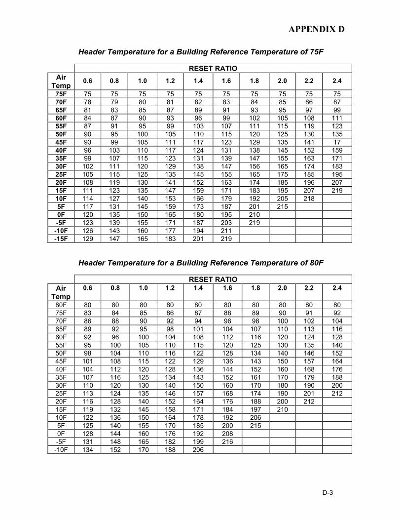
APPENDIX D
D-3
Header Temperature for a Building Reference Temperature of 75F
RESET RATIO Air
Temp 0.6 0.8 1.0 1.2 1.4 1.6 1.8 2.0 2.2 2.4
75F 75 75 75 75 75 75 75 75 75 75 70F 78 79 80 81 82 83 84 85 86 87 65F 81 83 85 87 89 91 93 95 97 99 60F 84 87 90 93 96 99 102 105 108 111 55F 87 91 95 99 103 107 111 115 119 123 50F 90 95 100 105 110 115 120 125 130 135 45F 93 99 105 111 117 123 129 135 141 17 40F 96 103 110 117 124 131 138 145 152 159 35F 99 107 115 123 131 139 147 155 163 171 30F 102 111 120 129 138 147 156 165 174 183 25F 105 115 125 135 145 155 165 175 185 195 20F 108 119 130 141 152 163 174 185 196 207 15F 111 123 135 147 159 171 183 195 207 219 10F 114 127 140 153 166 179 192 205 218 5F 117 131 145 159 173 187 201 215 0F 120 135 150 165 180 195 210 -5F 123 139 155 171 187 203 219 -10F 126 143 160 177 194 211 -15F 129 147 165 183 201 219
Header Temperature for a Building Reference Temperature of 80F
RESET RATIO Air
Temp 0.6 0.8 1.0 1.2 1.4 1.6 1.8 2.0 2.2 2.4
80F 80 80 80 80 80 80 80 80 80 80 75F 83 84 85 86 87 88 89 90 91 92 70F 86 88 90 92 94 96 98 100 102 104 65F 89 92 95 98 101 104 107 110 113 116 60F 92 96 100 104 108 112 116 120 124 128 55F 95 100 105 110 115 120 125 130 135 140 50F 98 104 110 116 122 128 134 140 146 152 45F 101 108 115 122 129 136 143 150 157 164 40F 104 112 120 128 136 144 152 160 168 176 35F 107 116 125 134 143 152 161 170 179 188 30F 110 120 130 140 150 160 170 180 190 200 25F 113 124 135 146 157 168 174 190 201 212 20F 116 128 140 152 164 176 188 200 212 15F 119 132 145 158 171 184 197 210 10F 122 136 150 164 178 192 206 5F 125 140 155 170 185 200 215 0F 128 144 160 176 192 208 -5F 131 148 165 182 199 216 -10F 134 152 170 188 206
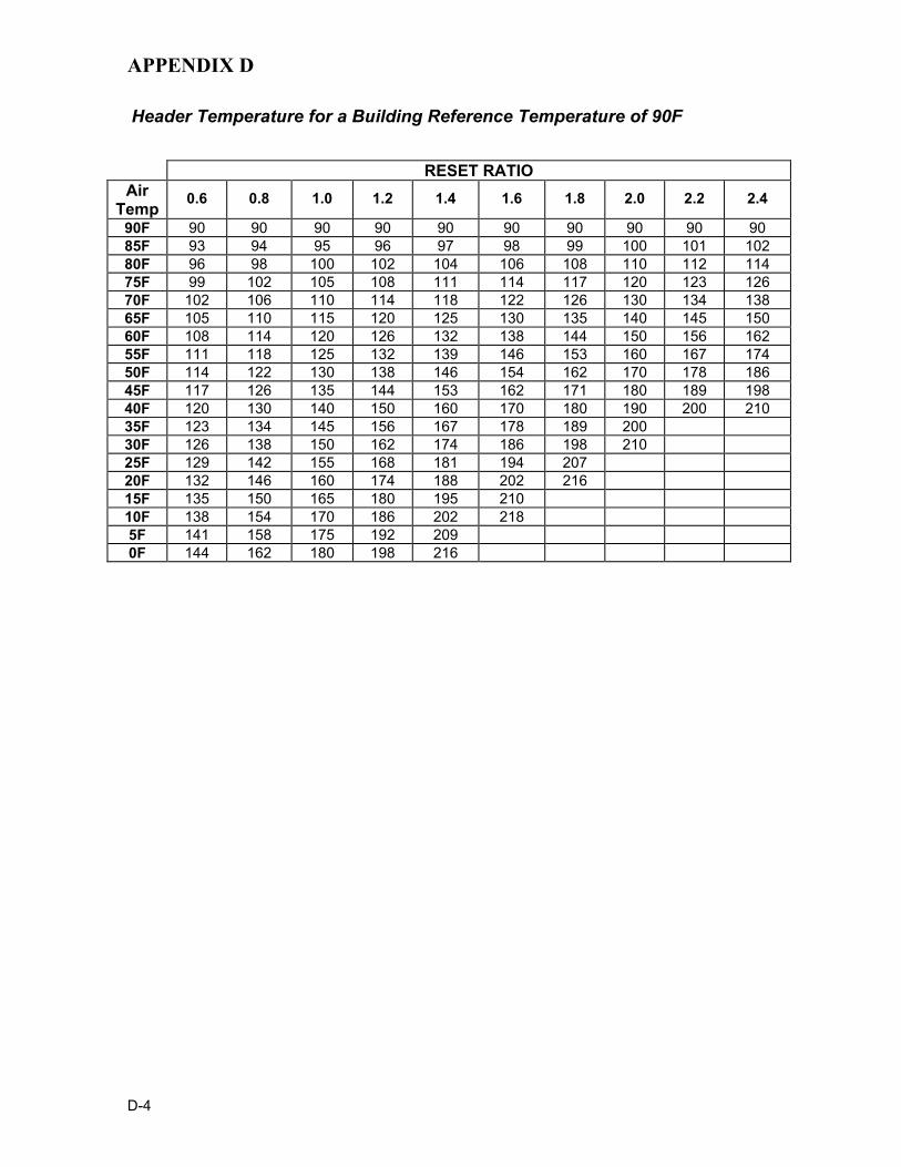
APPENDIX D
D-4
Header Temperature for a Building Reference Temperature of 90F
RESET RATIO Air
Temp 0.6 0.8 1.0 1.2 1.4 1.6 1.8 2.0 2.2 2.4
90F 90 90 90 90 90 90 90 90 90 90 85F 93 94 95 96 97 98 99 100 101 102 80F 96 98 100 102 104 106 108 110 112 114 75F 99 102 105 108 111 114 117 120 123 126 70F 102 106 110 114 118 122 126 130 134 138 65F 105 110 115 120 125 130 135 140 145 150 60F 108 114 120 126 132 138 144 150 156 162 55F 111 118 125 132 139 146 153 160 167 174 50F 114 122 130 138 146 154 162 170 178 186 45F 117 126 135 144 153 162 171 180 189 198 40F 120 130 140 150 160 170 180 190 200 210 35F 123 134 145 156 167 178 189 200 30F 126 138 150 162 174 186 198 210 25F 129 142 155 168 181 194 207 20F 132 146 160 174 188 202 216 15F 135 150 165 180 195 210 10F 138 154 170 186 202 218 5F 141 158 175 192 209 0F 144 162 180 198 216

APPENDIX E
E-1
BOILER DEFAULT SETTINGS
MENU & OPTION FACTORY DEFAULT
Setup Menu Password 0
Language English
Unit of Temp Fahrenheit
Comm Address 0
Baud Rate 9600
Configuration Menu Internal Setpt 130°F
Unit Type KC Boiler LN
Unit Size 1.0 MBTU
Fuel Type Natural Gas
Boiler Mode Constant Setpoint
Remote Signal (If Mode = Remote Setpoint, Direct Drive or Combination)
4 – 20 mA / 1-5V
Bldg Ref Temp (If Boiler Mode = Outdoor Reset)
70°F
Reset Ratio (If Boiler Mode = Outdoor Reset)
1.2
Outdoor Sensor Disabled System Start Tmp (If Outdoor Sensor = Enabled)
60°F
Setpt Lo Limit 60°F
Setpt Hi Limit 195°F Temp Hi Limit 195°F Max Valve Position 100%
Pump Delay Timer 0 min
Aux Start On Dly 0 sec
Failsafe Mode Shutdown
Analog Output Valve Position 0-10V CAUTION: DO NOT Change
Lo Fire Timer 2 sec
Setpt Limit Band (If Setpt Limiting = Enabled) 5°F
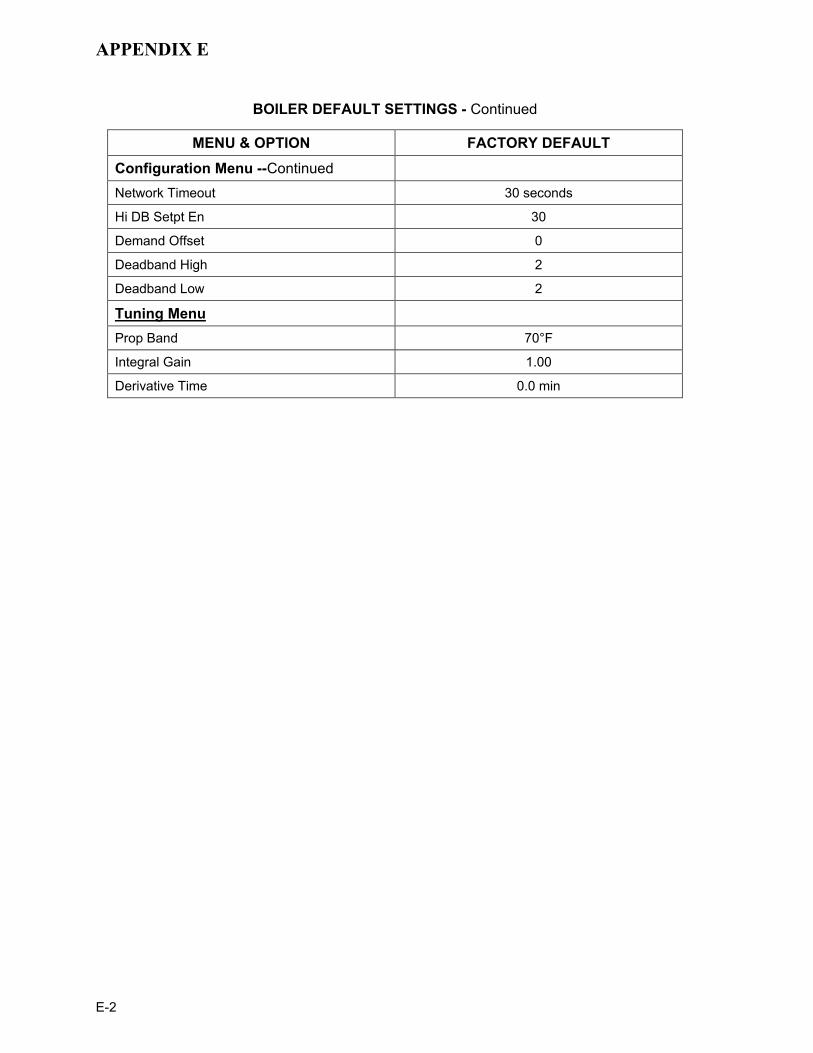
APPENDIX E
E-2
BOILER DEFAULT SETTINGS - Continued
MENU & OPTION FACTORY DEFAULT
Configuration Menu --Continued Network Timeout 30 seconds
Hi DB Setpt En 30
Demand Offset 0
Deadband High 2
Deadband Low 2
Tuning Menu Prop Band 70°F
Integral Gain 1.00
Derivative Time 0.0 min

APPENDIX F
F-1

APPENDIX F
F-2
35 (8
9)
49 (1
24)
57 (1
45)
47 (1
19)
30-1
/8
16-3
/4
23-1
/4
68-1
/277
-1/8
72-1
/2
14-3
/8
19 (4
8)22
-1/4
(57)
15-1
/2 (3
9)
29
3 (8
)
6 (1
5) I.
D.
FLU
E C
ON
N.
3/4
(2) D
IA.
(EN
CLO
SU
RE)
c.g.
PR
ESSU
RE
REL
IEF
4-15
0# F
LG'D
4-15
0# F
LG'D
SYS
. WA
TER
SU
PPL
Y
SYS.
WA
TER
RET
UR
N
AC S
ER
VIC
E C
ON
N.
3/4
CO
ND
UIT
120V
AC
SIN
GLE
PH
ASE
20 A
MP
W/G
RD
c.g.
3-1/
8
(184
)
5-3/
4 (1
5)
REM
OTE
ALA
RM
& C
ON
TRO
LC
ON
NEC
TIO
N -
3/4
CO
ND
UIT
1-1/
4NPT
GAS
INLE
T
(77)
(174
) (59)
(43)
(196
)
(37)
SHE
LL C
AP
VAL
VE
CO
MB.
AIR
INTA
KE(O
PTI
ON
AL
O.A
.IN
LET
AD
APTE
R
1"N
PTD
RAI
NVA
LVE
5/8"
I.D
MAL
E H
OS
EC
ON
DE
NSA
TED
RA
IN
MO
DE
L KC
STY
LE
KC
SE
RIE
S G
AS
FIR
ED
BO
ILE
RD
IME
NS
ION
AL
DR
AW
ING
AP
-A-8
16A
NO
TES
:1)
DR
AIN
VAL
VE
AN
D R
ELI
EF
VAL
VE
AR
E IN
CLU
DE
D S
EPA
RAT
ELY
IN S
HIP
MEN
T2)
A 1
/4" P
ER
FO
OT
FLU
E P
ITC
H B
ACK
TO
WA
RD
S T
HE
HE
ATER
MU
ST B
E
MA
INTA
INE
D T
O A
LLO
W T
HE
FLO
W O
F AN
Y C
ON
DEN
SAT
E FO
RM
ED
IN T
HE
FL
UE
TO
FLO
W T
O T
HE
DR
AIN
3) A
LL D
IME
NS
ION
S S
HO
WN
AR
E IN
INC
HES
(CEN
TIM
ETE
RS)
22 (5
6)(F
LOO
R F
LAN
GE)
(TY
P)
(OU
TLET
)
(INLE
T)
GK
2-1-
95
TYP.
4-PL
CS
()
14-3
/4 (3
7)
AERC
OIN
TER
NA
TIO
NAL
INC
.N
OR
THV
ALE
, NE
W J
ERS
EY 0
7647
CH
KD
APP
D
13-9
/16
(34.
4)
TRAI
N O
PTI
ON
" ON
LYC
ON
N. F
OR
"IR
I GAS
3/4"
NP
T G
AS V
ENT
AVAI
L. -
6" O
D)
ASM
E B
& P
V C
OD
E S
ECTI
ON
IV S
TAM
P H
HE
AT
EXC
HA
NG
ER D
ESIG
N S
TAN
DA
RD
S
SH
ELL
SID
E
PRE
SS. (
PSI
G)
150
MA
X. W
OR
KIN
G
225
TES
T P
RE
SS.
(PS
IG)
TEM
P. (
°F)
25
MA
XIM
UM
RE
V.

APPENDIX F
F-3
35(8
9)
49(1
24)
57(1
45)
47(1
19)
30-1
/8
16-3
/4
23-1
/4
68-1
/277
-1/8
72-1
/2
14-3
/8
19(4
8)22
-1/4
(57)
15-1
/2(3
9)
29
3(8)
6(15
)I.D
.FL
UE
CO
NN
.
3/4(
2)D
IA.
(EN
CLO
SUR
E)c.
g.
PRES
SUR
ER
ELIE
F
4-15
0# F
LG'D
4-15
0# F
LG'D
SYS.
WAT
ER S
UPP
LY
SYS.
WAT
ER R
ETU
RN
AC S
ERVI
CE
CO
NN
.3/
4 C
ON
DU
IT12
0VAC
SIN
GLE
PH
ASE
20 A
MP
W/G
RD
c.g.
3-1/
8
(184
)
5-3/
4(15
)
REM
OTE
ALA
RM
& C
ON
TRO
LC
ON
NEC
TIO
N -
3/4
CO
ND
UIT
1-1/
4NPT
GAS
INLE
T
(77)
(174
) (59)
(43)
(196
)
(37)
SHEL
L C
AP
VALV
E
CO
MB.
AIR
INTA
KE(O
PTIO
NAL
O.A
.IN
LET
ADAP
TER
1"N
PTD
RAI
NVA
LVE
5/8"
I.D
MAL
E H
OSE
CO
ND
ENSA
TED
RAI
N
HEA
T EX
CH
ANG
ER D
ESIG
N S
TAN
DAR
DS
SHEL
L SI
DE
87PR
ESS.
(PSI
G)
MAX
. WO
RKI
NG
MAX
IMU
MTE
MP.
(°F)
TEST
PR
ESS.
(PSI
G)
250
130.
5
ASM
E B
& PV
CO
DE
SEC
TIO
N IV
STA
MP
H
KCG
WB-
DP
GAS
FIR
ED B
OIL
ERD
IMEN
SIO
NAL
DR
AWIN
G
AP-A
-863
A
NO
TES:
1) D
RAI
N V
ALVE
AN
D R
ELIE
F VA
LVE
ARE
INC
LUD
ED S
EPAR
ATEL
Y IN
SH
IPM
ENT
2) A
1/4
" PER
FO
OT
FLU
E PI
TCH
BAC
K TO
WAR
DS
THE
HEA
TER
MU
ST B
E
MAI
NTA
INED
TO
ALL
OW
TH
E FL
OW
OF
ANY
CO
ND
ENSA
TE F
OR
MED
IN T
HE
FL
UE
TO F
LOW
TO
TH
E D
RAI
N3)
ALL
DIM
ENSI
ON
S SH
OW
N A
RE
IN IN
CH
ES (C
ENTI
MET
ERS)
22(5
6)(F
LOO
R F
LAN
GE)
(TYP
)
(OU
TLET
)
(INLE
T)
CZ
1002
06
TYP.
4-PL
CS
()
14-3
/4(3
7)
DW
N.B
YAP
PD
13-9
/16
(34.
4)
TRAI
N O
PTIO
N" O
NLY
CO
NN
. FO
R "I
RI G
AS3/
4" N
PT G
AS V
ENT
AVAI
L. -
6" O
D)
REV
.(P
RO
VIN
CE
OF
ALBE
RTA
INST
ALLA
TIO
NS)
INTE
RN
ATIO
NAL
INC
.AE
RCO
NO
RTH
VALE
, NEW
JER
SEY
0764
7

APPENDIX F
F-4
22
51
46
DESCRIPTIONQTYITEM PART NO.
BLOWER PROOF SWITCH161002-1443
37
24
11
38 39
25
26
23
XX NOT SHOWN IN THE DRAWING
TEMP./PRESS. GAUGE
DRAIN VALVE ASSEMBLY
1" NPT CLOSE NIPPLE - RED BRASS
1" NPT PRESSURE RELIEF VALVE
69087-
GM-122743
9-308
GP-5130-
19
**
11
12
1
1
1
1
TEMPERATURE SWITCH THERMOWELL
1/4" MNPT x 1/8" FNPT RED. BUSHING
112346349
52
51
50
1124334
161569
1237111
2
46
48
47
45
44
1GP-122821
122843
1234481
1
123536
GP-1224031
1
EXHAUST TEMPERATURE SWITCH
EXHAUST TEMP. SWITCH HARNESS
SHELL WIRING HARNESS
LOW WATER CUT-OFF
TEMPERATURE SWITCH
LOW PRESSURE GAS SWITCH
SHELL SENSOR
HOSE CLAMP 13/16" - 1-3/4"Ø RANGE
EXH. MANIFOLD TO COMB. CHAMB. GASKET
48
12
8
50
QTYITEM PART NO. DESCRIPTION
OTHER ACCESSORIES
COMBUSTION CHAMBER LINER (LOW NOX)
EXH. MANIFOLD TO LOWER HEAD SEAL
124839
GP-122537
17
18 1
1
GP-1890015 1
VENT MOUNTING FLANGE
CONDENSATE CUP ASSEMBLY
EXHAUST MANIFOLD
EXHAUST MANIFOLD INSULATION
EXHAUST MANIFOLD DRAIN HOSE
EXHAUST MANIFOLD
GP-122849
GP-123337
7
62
1
GM-20844-2
GP-20885
GP-122540
GM-123352
PART NO.
4
5
3
ITEM
2
1
1
1
QTY
1
GASKETS
DESCRIPTION
HEAT EXCHANGER ASS'Y
HEAT EXCHANGER
GM-20881
PART NO.ITEM
1
QTY
1
DESCRIPTION
INPUT/OUTPUT (I/O) BOX ASSEMBLY40
42
41
39
38
1161560
161450
1811981
1
GP-122569
GP-1224641
1
ITEM
37
PART NO.
161559
QTY
1
GAS TRAIN WIRING HARNESS
IGNITION CABLE ASSEMBLY
IGNITION TRANSFORMER
CONTROL BOX ASSEMBLY
DESCRIPTION
POWER BOX ASSEMBLY
CONTROLS
ITEM
22
PART NO.
124800-1
QTY
1
DESCRIPTIONGAS TRAIN ASSEMBLY
GAS TRAIN
1-1/2" X 1" REDUCING BUSHING18
1" NPT X 4" LG. NIPPLE - RED BRASS
1" NPT 90° ELBOW - BRONZE
8-22
GP-9-428
GP-122789
9
10 1
1
*
* INDICATE PRESSURE RELIEF VALVE SETTING
9
10
19
47
HIGH PRESS. GAS SWITCH53 1GP-122412
(30, 50, 75, 100, OR 150 PSI)
GP-1853213 1 SHELL GASKET
20
EXTERNAL GAS SHUT-OFF VALVEXX GP-123050 1
** -2 (30 AND 50 PSI RELIEF VALVE SETTING) -3 (75 AND 100 PSI RELIEF VALVE SETTING) -4 (150 PSI RELIEF VALVE SETTING)
12386354 1 1/8" NPT BALL VALVE
20
APPD.
DWN.BYSCALE
CZ
DATE
022505DATE PL-A-145(SH. 1 OF 2) H
INTERNATIONAL, INC.NORTHVALE, NJ 07647
PARTS LISTLOW NOX KC1000 WATER BOILER
AERCO
124800-2
*** - INCLUDES LOWER AND UPPER BURNER GASKETS,
SOLENOID VALVE HARNESS
STAGED IGNITION ASSEMBLY
56
55
124870 1124867 1
4544
IGNITOR, AND FLAME DETECTOR ASSEMBLY.
124801-1
124801-2
(LOW NOX; FM; NATURAL GAS)
(LOW NOX; IRI; NATURAL GAS)GAS TRAIN ASSEMBLY(LOW NOX; FM; PROPANE)GAS TRAIN ASSEMBLY
(LOW NOX; IRI; PROPANE)GAS TRAIN ASSEMBLY
65029 BLOWER MOTOR CAPACITOR
WITH AMETEK/A.O. SMITH MOTOR)BLOWER MOTOR CAPACITOR (FOR BLOWERS
(FOR BLOWERS WITH BALDOR MOTOR)BLOWER MOTOR CAPACITOR
(FOR ACI BLOWERS)
BLOWER AIR INLET SHUTTER
AIR INLET SCREEN
DAMPER TO BLOWER INLET HOSE
126 GP-122669
GP-122835
8500328
271
2 SPACER
124936
GP-122553
GP-16115225
24
1
1
DESCRIPTION
BLOWER (INCLUDES CAPACITOR 65029)
PART NO.
12493523
ITEM
1
QTY
BLOWER
KC1000 LOW NOx BURNER HEAD ONLY ASS'Y
BLOWER TO AIR VA. INLET HOSE
3/8" NPT x 3/8" O.D. TUBE AL. COMP. FTG.
1/8" NPT x 3/8" O.D. TUBE AL. COMP. FTG.
****
36***
24043
201258
GP-161147
GM-20934
34
35
33 201271
GP-18894
GP-122614
31
32
30
123581
PART NO.
GP-161146
ITEM
29
(REPLACEMENT KIT)
BURNER ASSEMBLY (LOW NOX)
AIR/FUEL VALVE (LOW NOX)
VALVE TO BURNER AIR HOSE
GAS INLET PIPE
1
1
1
1
1
BURNER AND AIR/FUEL VALVE
GAS PRESS. CONTROL TUBE
1
1
1
QTY
1
DESCRIPTION
**** - INCLUDES LOWER AND UPPER BURNER GASKETS,AND COMBUSTION CHAMBER LINER
BURNER & AIR/FUEL VALVE O-RING
OTHER PARTS
GP-122406
PART NO.ITEM
57
QTY
3
DESCRIPTION

APPENDIX F
F-5
636
45
15
49
17
52
18
29 433132 30
40
41
1
42
2
3
7
27 28
CPLG. W/PLUGSIGHT PORT
53
54
13
PARTS LIST
NORTHVALE, NJ 07647INTERNATIONAL, INC.
PL-A-145(SH. 2 OF 2)
LOW NOX KC1000 WATER BOILER
SCALEAPPD.
DWN.BY
DATE
CZ DATE 022505
AERCO
H5655
35 34 33
56
57 57

APPENDIX F
F-6
REV
.
KC10
00 L
OW
NO
x BO
ILER
IR
I GAS
TR
AIN
0223
05G
SD
WN
.BY
DAT
EN
TSSC
ALE
APPD
.D
ATE
SD-A
-660
C
NO
RTH
VALE
, NJ
076
47IN
TER
NAT
ION
AL, I
NC
.AE
RC
O
SSO
V AC
TUAT
OR
W/ P
.O.C
. SW
ITC
HP/
N 6
4047
SSO
V AC
TUAT
OR
W/O
P.O
.C. S
WIT
CH
P/N
690
38
HIG
H G
ASPR
ESSU
RE
SWIT
CH
PN: G
P-12
2412
TO A
IR-F
UEL
VAL
VE A
SS'Y
VEN
T TO
ATM
OSP
HER
EPE
R A
NSI
Z22
3.1
(NFP
A54)
HEA
TER
BO
UN
DAR
Y
3/4"
NO
RM
ALLY
OPE
NVE
NT
VALV
EP/
N G
P-12
2774
LOW
GAS
PR
ESSU
RE
SWIT
CH
P/N
GP-
1224
03TO
P VI
EW
1 1/
2" IR
I SSO
VP/
N 1
2413
71
1/4"
NPT
GAS
REG
ULA
TOR
P/N
124
802

APPENDIX F
F-7
12
6
11
5
9
1
7
10
8
2
4
14
13DO NOT CUT WIRES
ITEM NO. QTY. PART NO. DESCRIPTION1 1 124866 SOLENOID VALVE, 1/4" NPT2 1 122712 1/2" NPT, FLEX, GAS HOSE, 12" LONG3 1 123314 ELBOW, 1/4" NPT4 1 9-43 REDUCER BUSHING, 1/2" TO 1/4" NPT5 1 124933 UNION, 1/4" NPT6 1 124934 1/4" X 1/8" REDUCING COUPLING7 2 124088 NIPPLE, 1/4" NPT, C.S. 2 1/2" LONG8 1 124932 REDUCING COUPLING, 1/2" TO 1/4" NPT9 1 124910 NIPPLE, 1/4" NPT, CS. 9" LG
10 1 92076 1/4" NPT BALL VALVE11 1 124939 1/4" NPT ORIFICE PIPE NIPPLE12 1 124979 1/8" C.S. STREET ELBOW13 2 124891 FEMALE FAST-ON CONNECTOR14 1 12607-2 CLOSE NIPPLE, 1/4" NPT SCH.40, C.S.
LOW NOx STAGED IGNITION ASSEMBLY – 124867
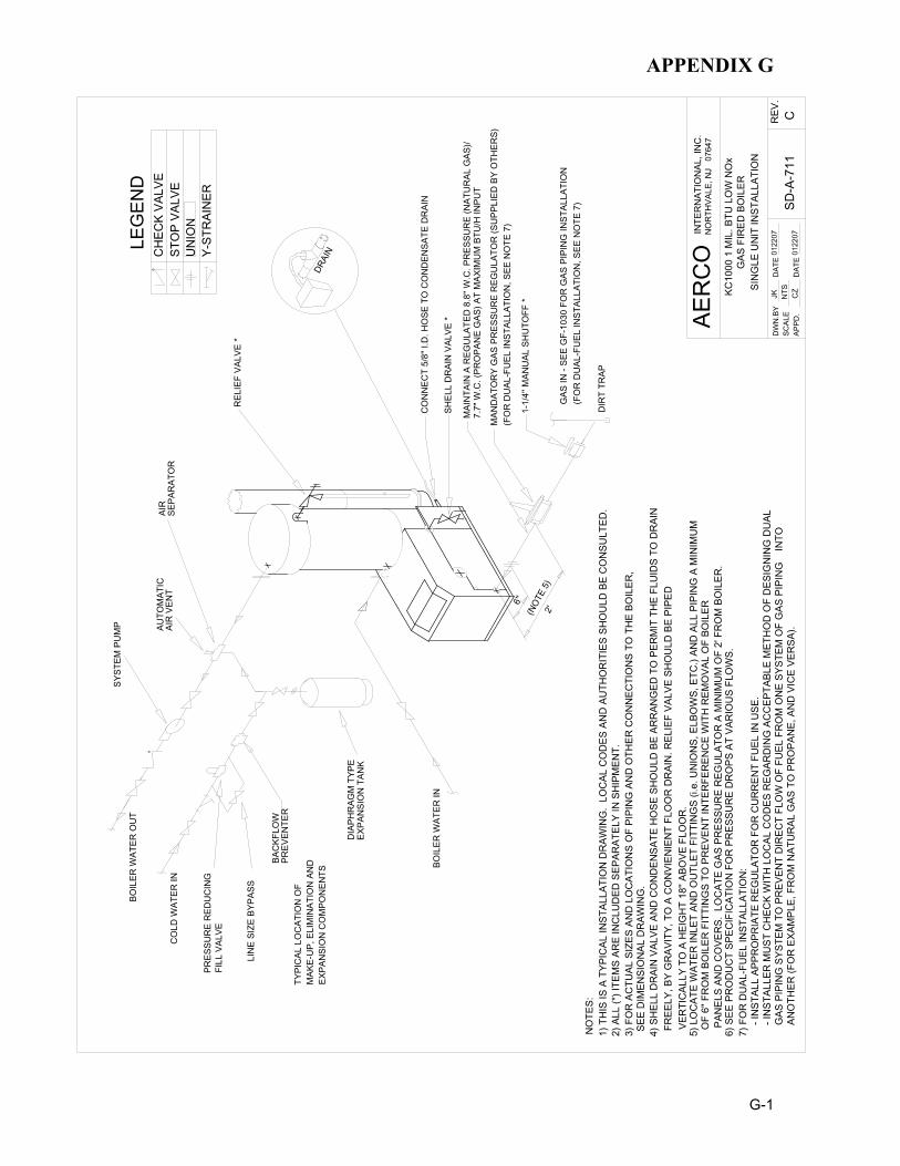
APPENDIX G
G-1
CO
NN
ECT
5/8'
' I.D
. HO
SE T
O C
ON
DEN
SATE
DR
AIN
SHEL
L D
RAI
N V
ALVE
*
REL
IEF
VALV
E *
(NOT
E 5)
6''
LIN
E SI
ZE B
YPAS
S
PRES
SUR
E R
EDU
CIN
GFI
LL V
ALVE
BAC
KFLO
WPR
EVEN
TER
EXPA
NSI
ON
TAN
KD
IAPH
RAG
M T
YPE
CO
LD W
ATER
IN
MAK
E-U
P, E
LIM
INAT
ION
AN
DTY
PIC
AL L
OC
ATIO
N O
F
SYST
EM P
UM
P
SEPA
RAT
OR
AIR
AIR
VEN
T
BOIL
ER W
ATER
IN
BOIL
ER W
ATER
OU
T
MAN
DAT
OR
Y G
AS P
RES
SUR
E R
EGU
LATO
R (S
UPP
LIED
BY
OTH
ERS)
7.7"
W.C
. (PR
OPA
NE
GAS
) AT
MAX
IMU
M B
TU/H
INPU
T
GAS
IN -
SEE
GF-
1030
FO
R G
AS P
IPIN
G IN
STAL
LATI
ON
MAI
NTA
IN A
REG
ULA
TED
8.8
'' W.C
. PR
ESSU
RE
(NAT
UR
AL G
AS)/
1-1/
4'' M
ANU
AL S
HU
TOFF
*
DIR
T TR
AP
2'
EXPA
NSI
ON
CO
MPO
NEN
TS
AUTO
MAT
IC
DRAI
NCH
ECK
VALV
ELE
GEN
D
STO
P VA
LVE
Y-ST
RAI
NER
UN
ION
GAS
FIR
ED B
OIL
ERKC
1000
1 M
IL. B
TU L
OW
NO
x
SIN
GLE
UN
IT IN
STAL
LATI
ON
NO
RTH
VALE
, NJ
076
47IN
TER
NAT
ION
AL, I
NC
.
APPD
.
DW
N.B
YSC
ALE
DAT
EC
Z01
2207
DAT
EJK N
TS01
2207
AER
CO
SD-A
-711
CREV
.
(FO
R D
UAL
-FU
EL IN
STAL
LATI
ON
, SEE
NO
TE 7
)
(FO
R D
UAL
-FU
EL IN
STAL
LATI
ON
, SEE
NO
TE 7
)
3) F
OR
AC
TUAL
SIZ
ES A
ND
LO
CAT
ION
S O
F PI
PIN
G A
ND
OTH
ER C
ON
NEC
TIO
NS
TO T
HE
BOIL
ER,
O
F 6'
' FR
OM
BO
ILER
FIT
TIN
GS
TO P
REV
ENT
INTE
RFE
REN
CE
WIT
H R
EMO
VAL
OF
BOIL
ER
FR
EELY
, BY
GR
AVIT
Y, T
O A
CO
NVI
ENIE
NT
FLO
OR
DR
AIN
. REL
IEF
VALV
E SH
OU
LD B
E PI
PED
6) S
EE P
RO
DU
CT
SPEC
IFIC
ATIO
N F
OR
PR
ESSU
RE
DR
OPS
AT
VAR
IOU
S FL
OW
S.
4) S
HEL
L D
RAI
N V
ALVE
AN
D C
ON
DEN
SATE
HO
SE S
HO
ULD
BE
ARR
ANG
ED T
O P
ERM
IT T
HE
FLU
IDS
TO D
RAI
N
5) L
OC
ATE
WAT
ER IN
LET
AND
OU
TLET
FIT
TIN
GS
(i.e.
UN
ION
S, E
LBO
WS,
ETC
.) AN
D A
LL P
IPIN
G A
MIN
IMU
M
PA
NEL
S AN
D C
OVE
RS.
LO
CAT
E G
AS P
RES
SUR
E R
EGU
LATO
R A
MIN
IMU
M O
F 2'
FR
OM
BO
ILER
.
SE
E D
IMEN
SIO
NAL
DR
AWIN
G.
VE
RTI
CAL
LY T
O A
HEI
GH
T 18
'' ABO
VE F
LOO
R.
1) T
HIS
IS A
TYP
ICAL
INST
ALLA
TIO
N D
RAW
ING
. LO
CAL
CO
DES
AN
D A
UTH
OR
ITIE
S SH
OU
LD B
E C
ON
SULT
ED.
2) A
LL (*
) ITE
MS
ARE
INC
LUD
ED S
EPAR
ATEL
Y IN
SH
IPM
ENT.
NO
TES:
7) F
OR
DU
AL-F
UEL
INST
ALLA
TIO
N:
-
INST
ALL
APPR
OPR
IATE
REG
ULA
TOR
FO
R C
UR
REN
T FU
EL IN
USE
.
- IN
STAL
LER
MU
ST C
HEC
K W
ITH
LO
CAL
CO
DES
REG
ARD
ING
AC
CEP
TABL
E M
ETH
OD
OF
DES
IGN
ING
DU
AL
GAS
PIP
ING
SYS
TEM
TO
PR
EVEN
T D
IREC
T FL
OW
OF
FUEL
FR
OM
ON
E SY
STEM
OF
GAS
PIP
ING
IN
TO
AN
OTH
ER (F
OR
EXA
MPL
E, F
RO
M N
ATU
RAL
GAS
TO
PR
OPA
NE,
AN
D V
ICE
VER
SA).

APPENDIX G
G-2
CO
NN
ECT
5/8'
' I.D
. HO
SE T
O C
ON
DEN
SATE
DR
AIN
SHEL
L D
RAI
N V
ALVE
*
REL
IEF
VALV
E *
PAN
ELS
AND
CO
VER
S. L
OC
ATE
GAS
PR
ESSU
RE
REG
ULA
TOR
A M
INIM
UM
OF
2' F
RO
M B
OIL
ER.
5) L
OC
ATE
WAT
ER IN
LET
AND
OU
TLET
FIT
TIN
GS
(i.e.
UN
ION
S, E
LBO
WS,
ETC
.) AN
D A
LL P
IPIN
G A
MIN
IMU
M
2) A
LL (*
) ITE
MS
ARE
INC
LUD
ED S
EPAR
ATEL
Y IN
SH
IPM
ENT.
REL
IEF
VALV
E SH
OU
LD B
E PI
PED
VER
TIC
ALLY
TO
A H
EIG
HT
18'' A
BOVE
FLO
OR
.
4) S
HEL
L D
RAI
N V
ALVE
AN
D C
ON
DEN
SATE
HO
SE S
HO
ULD
BE
ARR
ANG
ED T
O P
ERM
IT
NO
TES:
6) S
EE P
RO
DU
CT
SPEC
IFIC
ATIO
N F
OR
PR
ESSU
RE
DR
OPS
AT
VAR
IOU
S FL
OW
S.
(NOT
E 5)
6''
1) T
HIS
IS A
TYP
ICAL
INST
ALLA
TIO
N D
RAW
ING
.
3) F
OR
AC
TUAL
SIZ
ES A
ND
LO
CAT
ION
S O
F PI
PIN
G A
ND
OTH
ER
1-1/
4'' M
ANU
AL S
HU
TOFF
*
DIR
T TR
AP
2'
BOIL
ER W
ATER
IN
EXPA
NSI
ON
CO
MPO
NEN
TS
TYPI
CAL
LO
CAT
ION
OF
MAK
E-U
P, E
LIM
INAT
ION
AN
D
DIA
PHR
AGM
TYP
EEX
PAN
SIO
N T
ANK
PREV
ENTE
RBA
CKF
LOW
CO
LD W
ATER
IN
FILL
VAL
VEPR
ESSU
RE
RED
UC
ING
LIN
E SI
ZE B
YPAS
S
AUTO
MAT
ICAI
R V
ENT
AIR
SYST
EM P
UM
P
SEPA
RAT
OR
BOIL
ER W
ATER
OU
T
2'-10
'HE
ADER
TEM
P.
SENS
OR
DRAI
N
GAS
FIR
ED B
OIL
ERM
ULT
IPLE
UN
IT IN
STAL
LATI
ON
CO
NN
ECTI
ON
S TO
TH
E BO
ILER
, SEE
DIM
ENSI
ON
AL D
RAW
ING
.
THE
FLU
IDS
TO D
RAI
N F
REE
LY, B
Y G
RAV
ITY,
TO
A C
ON
VIEN
IEN
T FL
OO
R D
RAI
N.
OF
6'' F
RO
M B
OIL
ER F
ITTI
NG
S TO
PR
EVEN
T IN
TER
FER
ENC
E W
ITH
REM
OVA
L O
F BO
ILER
NO
RTH
VALE
, NJ
076
47IN
TER
NAT
ION
AL, I
NC
.
APPD
.
DW
N.B
YSC
ALE
DAT
EC
Z01
2207
DAT
EJK N
TS01
2207
AER
CO
SD-A
-712
CREV
.
CH
ECK
VALV
E
STO
P VA
LVE
CO
MB.
BAL
ANC
ING
/
Y-ST
RAI
NER
UN
ION
STO
P VA
LVE
LEG
END
KC10
00 1
MIL
. BTU
LO
W N
Ox
LOC
AL C
OD
ES A
ND
AU
THO
RIT
IES
SHO
ULD
BE
CO
NSU
LTED
.
MAI
NTA
IN A
REG
ULA
TED
8.8
'' W
.C.
PRES
SUR
E (N
ATU
RAL
GAS
)/7.7
" W.C
. (P
RO
PAN
E G
AS) A
T M
AXIM
UM
BTU
/H
INPU
T
MAN
DAT
OR
Y G
AS P
RES
SUR
E R
EGU
LATO
R (S
UPP
LIED
BY
OTH
ERS)
(FO
R D
UAL
-FU
EL IN
STAL
LATI
ON
, SEE
NO
TE 8
)
GAS
IN -
SEE
GF-
1030
FO
R G
AS P
IPIN
G IN
STAL
LATI
ON
(FO
R D
UAL
-FU
EL IN
STAL
LATI
ON
, SEE
NO
TE 8
)
8) F
OR
DU
AL-F
UEL
INST
ALLA
TIO
N:
- IN
STAL
L AP
PRO
PRIA
TE R
EGU
LATO
R F
OR
CU
RR
ENT
FUEL
IN U
SE.
- IN
STAL
LER
MU
ST C
HEC
K W
ITH
LO
CAL
CO
DES
REG
ARD
ING
AC
CEP
TABL
E M
ETH
OD
OF
DES
IGN
ING
DU
AL G
AS P
IPIN
GSY
STEM
TO
PR
EVEN
T D
IREC
T FL
OW
OF
FUEL
FR
OM
ON
E SY
STEM
OF
GAS
PIP
ING
IN
TO A
NO
THER
(FO
R E
XAM
PLE,
FRO
M N
ATU
RAL
GAS
TO
PR
OPA
NE,
AN
D V
ICE
VER
SA).
7) B
OIL
ERS
SHO
ULD
BE
PIPE
D R
EVER
SE R
ETU
RN
AS
SHO
WN
OR
BAL
ANC
ING
DEV
ICES
ON
TH
E O
UTL
ETS
OF
THE
HEA
TER
S SH
OU
LD B
E EM
PLO
YED
.

APPENDIX G
G-3
CO
NN
ECT
5/8'
' I.D
. HO
SE T
O C
ON
DEN
SATE
DR
AIN
SHEL
L D
RAI
N V
ALVE
REL
IEF
VALV
E
SD-A
-713
BOIL
ERS
CO
MBI
NAT
ION
HEA
TIN
G &
KC L
OW
NO
x SE
RIE
S G
AS F
IRED
IN
TER
FER
ENC
E W
ITH
REM
OVA
L O
F BO
ILER
PAN
ELS
AND
CO
VER
S. L
OC
ATE
GAS
PR
ESSU
RE
REG
ULA
TOR
A M
INIM
UM
OF
2' F
RO
M B
OIL
ER.
5) L
OC
ATE
WAT
ER IN
LET
AND
OU
TLET
FIT
TIN
GS
(i.e.
UN
ION
S, E
LBO
WS,
ETC
.) AN
D A
LL P
IPIN
G A
MIN
IMU
M O
F 6'
' FR
OM
BO
ILER
FIT
TIN
GS
TO P
REV
ENT
3) A
LL (*
) ITE
MS
ARE
INC
LUD
ED S
EPAR
ATEL
Y IN
SH
IPM
ENT.
TO A
CO
NVE
NIE
NT
FLO
OR
DR
AIN
. R
ELIE
F VA
LVE
SHO
ULD
BE
PIPE
D V
ERTI
CAL
LY T
O A
HEI
GH
T 18
'' ABO
VE F
LOO
R.
2) S
HEL
L D
RAI
N V
ALVE
AN
D C
ON
DEN
SATE
HO
SE S
HO
ULD
BE
ARR
ANG
ED T
O P
ERM
IT T
HE
FLU
IDS
TO D
RAI
N F
REE
LY, B
Y G
RAV
ITY ,
NO
TES:
Y ST
RAI
NER
UN
ION
CH
ECK
VALV
E
STO
P VA
LVE
6) S
EE P
RO
DU
CT
SPEC
IFIC
ATIO
N F
OR
PR
ESSU
RE
DR
OPS
AT
VAR
IOU
S FL
OW
S.
(NOT
E 5)6''
GAS
SU
PPLY
4) T
HIS
IS A
TYP
ICAL
INST
ALLA
TIO
N D
RAW
ING
. LO
CAL
CO
DES
AN
D A
UTH
OR
ITIE
S SH
OU
LD B
E C
ON
SULT
ED.
1) F
OR
AC
TUAL
SIZ
ES A
ND
LO
CAT
ION
S O
F PI
PIN
G A
ND
OTH
ER C
ON
NEC
TIO
NS
TO T
HE
BOIL
ER, S
EE D
IMEN
SIO
NAL
DR
AWIN
G.
1-1/
4'' M
ANU
AL S
HU
TOFF
DIR
T TR
AP
2'
JK1-
22-0
7N
TSB
C
LEG
END
HEA
TIN
GSY
STEM
RET
UR
N
EXPA
NSI
ON
CO
MPO
NEN
TS
TYPI
CAL
LO
CAT
ION
OF
MAK
E-U
P, E
LIM
INAT
ION
AN
DSU
PPLY
DIA
PHR
AGM
TYP
EEX
PAN
SIO
N T
ANK
PREV
ENTE
RBA
CKF
LOW
WAT
ER
FILL
VAL
VEPR
ESSU
RE
RED
UC
ING
LIN
E SI
ZE B
YPAS
S
AUTO
MAT
ICAI
R V
ENT
AIR
SYST
EM P
UM
P
SEPA
RAT
OR
HEA
TIN
GSY
STEM
SUPP
LY
2'-10
'HE
ADER
TEM
P.
SENS
OR
2'(N
OTE
5)6''
TO D
RAIN
CO
MB.
BAL
ANC
ING
/STO
P VA
LVE
DO
MES
TIC
WAT
ER B
OIL
ER P
LAN
T
MO
TOR
IZED
GLO
BE O
R B
ALL
VALV
EW
ITH
EN
D S
WIT
CH
DO
MES
TIC
WAT
ERST
OR
AGE
TAN
K
CO
MBI
NAT
ION
SYST
EM P
UM
P
*
*
SWIN
G C
HEC
K VA
LVE
SUPP
LY O
UTL
ET4"
150
FLG
'D
4" 1
50 F
LG'D
RET
UR
N IN
LET
APPD
.C
HKD
.
DW
N.B
YSI
ZESC
ALE
DAT
ER
EV.
NO
RTH
VALE
, NJ
076
47IN
TER
NAT
ION
AL, I
NC
.AE
RC
O
CZ
1-22
-07
7) F
OR
DU
AL-F
UEL
INST
ALLA
TIO
N:
- IN
STAL
L AP
PRO
PRIA
TE R
EGU
LATO
R F
OR
CU
RR
ENT
FUEL
IN U
SE.
- IN
STAL
LER
MU
ST C
HEC
K W
ITH
LO
CAL
CO
DES
REG
ARD
ING
AC
CEP
TABL
E M
ETH
OD
OF
DES
IGN
ING
DU
AL G
AS P
IPIN
G S
YSTE
M T
OPR
EVEN
T D
IREC
T FL
OW
OF
FUEL
FR
OM
ON
E SY
STEM
OF
GAS
PIP
ING
IN
TO A
NO
THER
(FO
R E
XAM
PLE,
FR
OM
NAT
UR
AL G
AS T
OPR
OPA
NE,
AN
D V
ICE
VER
SA).
GAS
SU
PPLY
- SE
E G
F-10
30 F
OR
GAS
PIP
ING
INST
ALLA
TIO
N(F
OR
DU
AL-F
UEL
INST
ALLA
TIO
N, S
EE N
OTE
7)
MAI
NTA
IN A
REG
ULA
TED
8.8
'' W.C
. PR
ESSU
RE
(NAT
UR
AL G
AS) /
7.7
" W.C
. (P
RO
PAN
E G
AS) A
T M
AXIM
UM
BTU
/H IN
PUT
MAN
DAT
OR
Y G
AS P
RES
SUR
E R
EGU
LATO
R (S
UPP
LIED
BY
OTH
ERS)
(FO
R D
UAL
-FU
EL IN
STAL
LATI
ON
, SEE
NO
TE 7
)

APPENDIX H
H-1
CLOSURE SWITCHPROOF OF
GRN
WHT
60 H
z
120
VA
C IN
20 A N
EU
GN
D
HO
T
NC
C
GN
H
GN
D
HG
N
12
34
56
12
34
56
78
91
23
45
67
89
1011
1213
1415
12
34
56
78
910
1112
CO
NTR
OL
BO
X C
ON
NE
CTO
RS
LOW GAS PRESS. SW.
BLOWER PROOF SW.
SAFETY SHUTOFF VALVE
OV
ER
TE
MP
ER
ATU
RE
SW
ITC
HE
S
BLO
WE
R
IGNITOR
TRA
NS
FOR
ME
R
WATER LEVEL PROBE
FLAME ROD
AC WIRING BOX
SH
ELL
TEM
P.
SE
NS
OR
GA
S F
IRE
DS
YS
TEM
SC
HE
MA
TIC
1616
13
16-P
IN C
ON
NE
CTO
R19
-PIN
CO
NN
EC
TOR
9-P
IN C
ON
NE
CTO
R7-
PIN
CO
NN
EC
TOR
MA
NU
AL
RE
SE
T
HIGH GAS PRESS. SW.
BLK
STE
PP
ING
MO
TOR
PURGEPOSITION
IGNITIONPOSITION
SWITCH
SWITCH
AIR
/FU
EL
VA
LVE
BLKYEL
WHT
535K
C
B
A3
RED
GRN
BLU
210
K
1
(KC
100
0)
150
151
153
152
153
152
151
150
7
133
134
1819
1716
1415
1613
154
AU
TO R
ES
ET
IGN
ITIO
N
265
200
BLO
WE
R
XFO
RM
ER
RE
LAY
24 V
AC
194
193
192
191
190
195
201
206
209
208
210
203
202
204
FUS
E
FUS
E
203
206
207
265
205
210
20420
2
207
209
200
201
SE
NS
OR
* FF
WD
TEM
P.
180
* BTU PUMP
183
183
184
182
191
141
184
194
193
137
155
136 15
413
519
213
818
214
019
019
517
217
117
016
916
816
716
616
516
416
316
216
114
914
814
714
614
5
141
149
148
146
145
147
181
136
137
209
208
* W
ATE
R H
EA
TER
S O
NLY
6-P
IN C
ON
NE
CTO
R
SH
EE
T 1
OF
2
321
TO C
ON
TRO
L B
OX
320
321
322
TO B
UR
NE
R
GN
D
AS
FO
LLO
WS
UN
LES
S O
THE
RW
ISE
SP
EC
IFIE
D
THIR
D A
NG
LE P
RO
JEC
TIO
N
ALL
DIM
EN
SIO
NS
AR
E IN
INC
HE
S A
ND
ALL
TO
LER
AN
CE
S A
RE
XX
±.0
15 X
XX
± .0
05 F
RA
CTI
ON
S 1
/32±
AN
GLE
S ±
1°
PE
RP
EN
DIC
ULA
RIT
Y/P
AR
ALL
ELI
SM
/FLA
TNE
SS
.003
TO
TAL
DIA
ME
TER
S O
N A
CO
MM
ON
AX
IS
ALL
DIM
EN
SIO
NS
AR
E A
FTE
R F
INIS
H O
R P
LATI
NG
RE
LEA
SE
D F
OR
PR
OD
UC
TIO
N
THE
SE
DR
AW
ING
S A
ND
/OR
SP
EC
IFIC
ATI
ON
S A
RE
TH
E P
RO
PE
RTY
OF
AE
RC
O IN
TER
NA
TIO
NA
L, IN
C. T
HE
Y A
RE
ISS
UE
D IN
STR
ICT
CO
NFI
DE
NC
E A
ND
SH
ALL
NO
T B
E R
EP
RO
DU
CE
D, C
OP
IED
, OR
US
ED
AS
TH
E B
AS
IS F
OR
MA
NU
FAC
TUR
E O
R S
ALE
OF
AP
PA
RA
TUS
WIT
HO
UT
PE
RM
ISS
ION
OF
THE
OW
NE
R.
FIM
AR
EV
ISIO
NS
RE
VE
CO
0613
02M
DC
K'D
DA
TEB
Y
159
PA
RIS
AV
E, N
OR
THV
ALE
, N.J
.
0613
02M
DO
RIG
INA
L
BD
RA
WN
BY
:D
ATE
:
DA
TE:
CH
EC
KE
D B
Y:
DW
G. S
IZE
MA
T'L
SP
EC
.:
TITL
E
.005
TO
TAL
CRE
VD
WG
. NO
.:
BFY
PA
DD
ED
GR
OU
ND
WIR
ES
320
, 321
& 3
2210
0703
JM03
1603
GE
NE
RA
L C
OR
RE
CTI
ON
S T
O S
CH
EM
ATI
CC
GK
UM
C
173
1K
INTE
RN
ATI
ON
AL
INC
.

APPENDIX H
H-2
CO
NTR
OL
BO
X C
ON
NE
CTO
RS
GA
S F
IRE
D B
OIL
ER
SY
STE
MW
IRIN
G S
CH
EM
ATI
C
1616
13
1210
1113
1416
1517
1819
2120
2223
24
24-P
IN C
ON
NE
CTO
R
241
240
242
243
244
245
251
246
250
247
252
254
253
96
87
54
31
2 212
220
221
211
219
16-P
IN C
ON
NE
CTO
R
85
46
79
12
311
1614
1513
1210
226
213
214
216
215
76
7
5
34
6
12
OUTIN
OUTIN
INOUT
FAULTRELAY
NOT USED
DELAYED INTLK
EXHAUST TEMP
REMOTE INTLK
N.O.
C43
5
12
NOT USED
N.C.C
N.O.N.C. RELAY
AUX
121314
11SENSOR EXCIT. (12 VDC)
BMS (PWM) IN
ANALOG IN
OXYGEN SENSOR IN
FLOW SENSOR IN
CO SENSOR IN
+
-
-
+
-
+-
+
AUX SENSOR INSENSOR COMMON IN
-
+
1 OUTDOOR AIR SENSOR IN
987
5
34
2
6
10
OUT
IN
LONWORKSAB
GND
4
1
21
-
+
2
21
3
3
ANALOG OUT
1516 SHIELD
B
RS-485 IN
A
12
43
78
65
910
1211
87
65
43
21
87
65
43
21
1211
109
1314
15
231
234
232
233
238
236
235
237
239
INP
UT/
OU
TPU
T B
OX
(KC
100
0)
+
-
LS2
1
LS1
LS4
LS3
J3J2
J1
SH
EE
T 2
OF
2
AS
FO
LLO
WS
UN
LES
S O
THE
RW
ISE
SP
EC
IFIE
D
THIR
D A
NG
LE P
RO
JEC
TIO
N
ALL
DIM
EN
SIO
NS
AR
E IN
INC
HE
S A
ND
ALL
TO
LER
AN
CE
S A
RE
XX
±.0
15 X
XX
± .0
05 F
RA
CTI
ON
S 1
/32±
AN
GLE
S ±
1°
PE
RP
EN
DIC
ULA
RIT
Y/P
AR
ALL
ELI
SM
/FLA
TNE
SS
.003
TO
TAL
DIA
ME
TER
S O
N A
CO
MM
ON
AX
IS
ALL
DIM
EN
SIO
NS
AR
E A
FTE
R F
INIS
H O
R P
LATI
NG
SE
E S
HE
ET
ON
E
THE
SE
DR
AW
ING
S A
ND
/OR
SP
EC
IFIC
ATI
ON
S A
RE
TH
E P
RO
PE
RTY
OF
AE
RC
O IN
TER
NA
TIO
NA
L, IN
C. T
HE
Y A
RE
ISS
UE
D IN
STR
ICT
CO
NFI
DE
NC
E A
ND
SH
ALL
NO
T B
E R
EP
RO
DU
CE
D, C
OP
IED
, OR
US
ED
AS
TH
E B
AS
IS F
OR
MA
NU
FAC
TUR
E O
R S
ALE
OF
AP
PA
RA
TUS
WIT
HO
UT
PE
RM
ISS
ION
OF
THE
OW
NE
R.
RE
VIS
ION
SR
EV
EC
OC
K'D
DA
TEB
Y
159
PA
RIS
AV
E, N
OR
THV
ALE
, N.J
.
0613
02M
DO
RIG
INA
L
BD
RA
WN
BY
:D
ATE
:
DA
TE:
CH
EC
KE
D B
Y:
DW
G. S
IZE
MA
T'L
SP
EC
.:
TITL
E
.005
TO
TAL
CRE
VD
WG
. NO
.:
16
INTE
RN
ATI
ON
AL
INC
.
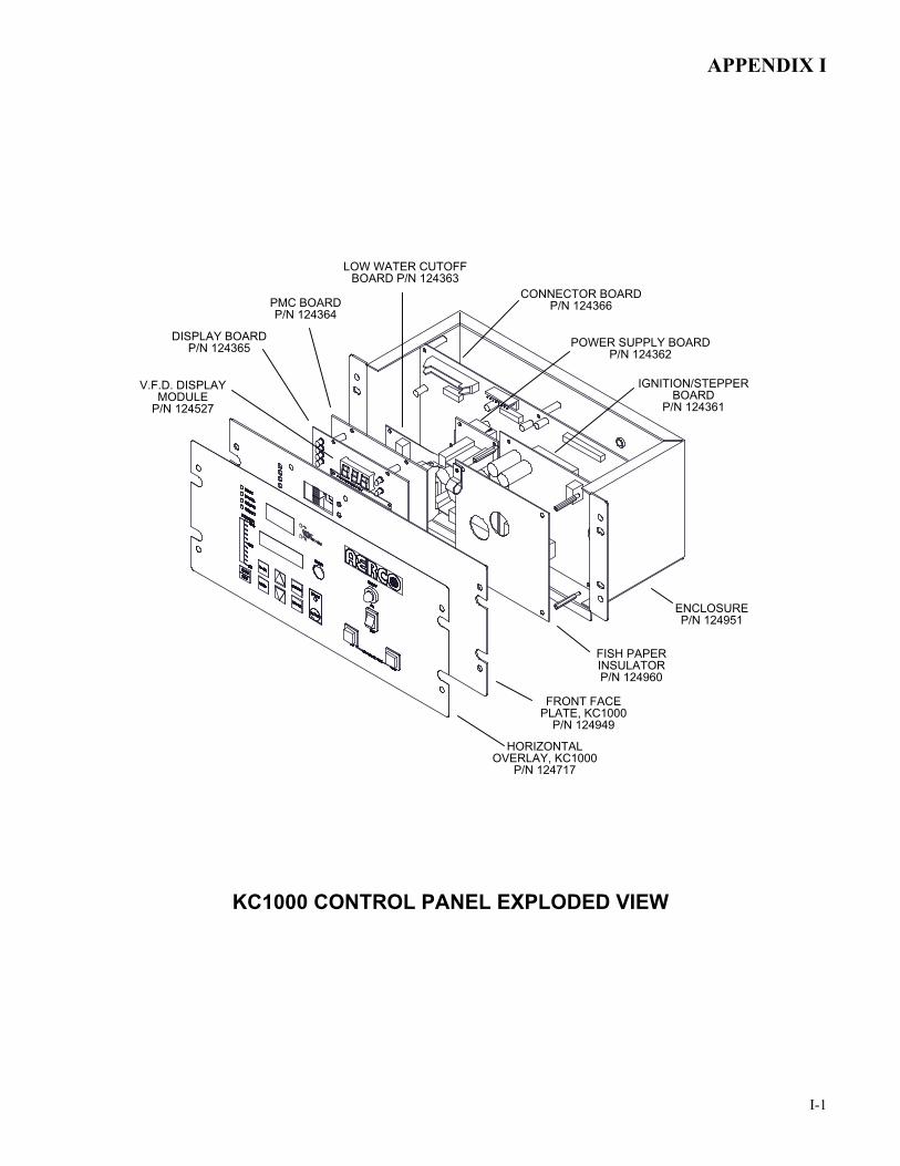
APPENDIX I
I-1
CONNECTOR BOARDP/N 124366
POWER SUPPLY BOARDP/N 124362
LOW WATER CUTOFF BOARD P/N 124363
PMC BOARDP/N 124364
IGNITION/STEPPER BOARD
P/N 124361
V.F.D. DISPLAYMODULE
P/N 124527
DISPLAY BOARDP/N 124365
FISH PAPER INSULATORP/N 124960
FRONT FACE PLATE, KC1000
P/N 124949
HORIZONTAL OVERLAY, KC1000
P/N 124717
KC1000 CONTROL PANEL EXPLODED VIEW
ENCLOSUREP/N 124951
KC1000 CONTROL PANEL EXPLODED VIEW

APPENDIX I
I-2
P1P2P3P4P5P6
SHELL HARNESSCONNECTOR
(19 PIN)
INTERLOCK HARNESSCONNECTOR
(16 PIN)
EXT. SENSOR/COMMHARNESS CONNECTOR
(24 PIN)
GAS TRAIN HARNESSCONNECTOR
(9 PIN)
A/F VALVEHARNESS
CONNECTOR(16 PIN)
SENSORHARNESS
CONNECTOR(7 PIN)
TO INPUT/OUTPUT (I/O) BOX
KC1000 CONTROL PANEL REAR VIEW

APPENDIX J
J-1
KC1000 LOW NOx DUAL-FUEL SWITCH-OVER INSTRUCTIONS
The KC1000 Low NOx Boiler is shipped from the factory configured for either natural gas or propane operation, as specified on the Sales Order. However, if required, the unit’s operating configuration can be easily switched from natural gas to propane (or vice-versa) by performing a simple change to the spring contained in the unit’s differential regulator.
The extra spring required to switch from natural gas to propane, or from propane to natural gas is included with the unit accessories (see Chapter 2, para. 2.2). Units configured for natural gas operation include a zinc-plated regulator spring, part no. 124803. Units configured for propane operation include a brown painted spring, part no. 122548.
The following instructions provide the steps necessary to convert the unit from Natural Gas to Propane operation. Proceed as follows:
1. Shut down the unit and close the external gas supply valve.2. Remove the sheet metal covers and locate the differential regulator on the left side of
the unit.3. Refer to Figure 1 and remove the cap on the differential regulator.4. Using a flat-blade screwdriver, remove the adjustment screw by turning it counter-
clockwise. Remove the installed zinc-plated regulator spring (124803) used for NaturalGas operation. DO NOT DISCARD THE REMOVED SPRING.
5. Install the brown painted spring (122548) required for Propane operation.6. Replace the regulator adjustment screw. Rotate the screw clockwise to a depth of 1-1/2
inches from the top of the regulator housing.7. Upon completion of the spring change, perform the combustion calibration procedures in
Section 4 of this Instruction Manual.
REGULATOR CAP
CAP GASKET
ADJUSTMENTSCREW
SPRING(PARTIALLY REMOVED)
DIFFERENTIAL GAS PRESSURE REGULATOR
FIGURE 1. REGULATOR SPRING REPLACEMENT

APPENDIX K
K-1
RECOMMENDED SPARE PARTS LISTS
NOTE Refer to the Parts List Illustrations in Appendix F for the locations of the recommended and optional spare parts listed in the following Tables.
Table K-1. Recommended Emergency Spare Parts
DESCRIPTION PART NUMBER
120 VAC Single-Phase Blower 124935 Siemens SSOV Actuator - Used on: • ALL FM gas train models• Downstream SSOV of IRI gas train models
64047
Siemens SSOV Actuator Without Proof of Closure Switch - Used on: • Upstream SSOV of IRI gas train models
69038
Over-Temperature Switch GP-122822
Table K-2. Spare Parts Recommended for Maintenance DESCRIPTION PART NUMBER
Ignitor 124570 Flame Detector 124837 Combustion Chamber liner 124839 Exhaust Manifold/Combustion Chamber gasket GP-122537 Manifold/Tubesheet gasket GP-18900 Burner gasket GP-18899 Burner release gasket GP-122551 Head gasket GP-18532 Head release gasket GP-18556 BTU hot water orifice GP-122760 BTU cold water orifice GP-122401
Table K-3. Optional Spare Parts DESCRIPTION PART NUMBER
C-More Control Box 181198 Burner Head Assembly 24043