Embed Size (px)
Citation preview
Distributed By:
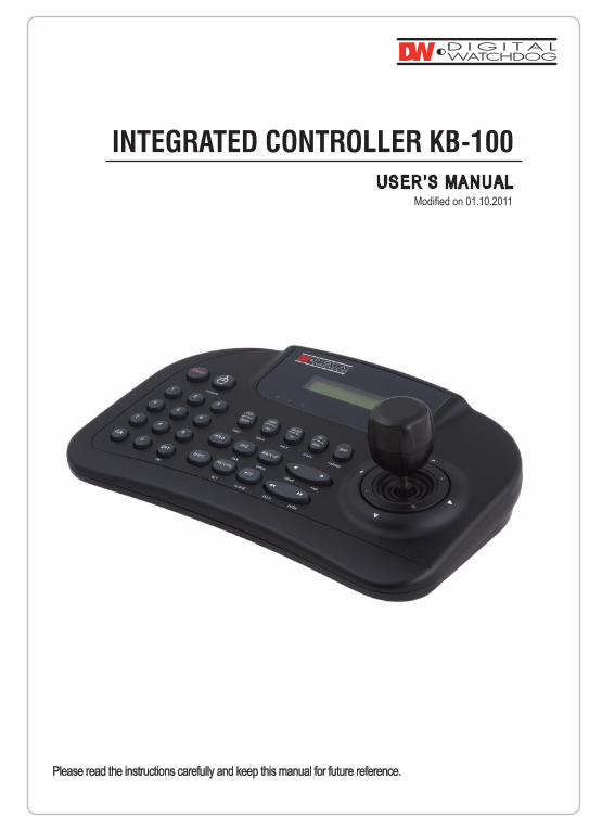
Please read the instructions carefully and keep this manual for future reference.
USER’S MANUALModified on 01.10.2011
PRECAUTIONS1. Warning2. Caution3. MaintenanceMAIN FUNCTIONS AND FEATURES 1. Summary2. features 3. Product and Accessories4. Changing the BatteryCONTROLLER BUTTON OVERVIEW PART NAME & FUNCTION CONNECTION1. RS-485 / RS-422 Connection2. DVR Connection3. KB-100 and DVR Mouse Function Use4. System ConfigurationSTARTDVR CONTROL CONTROLLER MAIN SETUP PTZ CONTROL SETTING JOYSTICK CALIBRATIONBASIC FUNCTION & CONTROL SPECIFICATIONSDIMENSIONS
CONTENTS
PRECAUTIONS
To prevent risk or damage while operating the KB-100, you must take note of the following information.
Please be aware of the Warnings and Cautions. They are defined as follows.
WARNING: Violation of the instructions may cause death or injury. CAUTION: Violation of the instructions may cause personal injury or product damage.
WARNING
CAUTION
- Before using the product, please be sure to read the user manual. - Install this product in a safe place that is free from external vibration. - Do not place conductive materials (screwdrier, coin, iron, etc) or water near the product. - Use only the indicated power supply (DC12V).- Do not use this product near flammable substances.- Do not touch electrical parts with wet hands. - When the product is not operating normally, contact your seller or service center. - Never disassemble the equipment. The Warrantor is not responsible for problems caused by disassembly done by the user.
- This device is recommended for indoor use only. It should not be used outdoor, where it is exposed to rain or moisture. - Dropping the product in water may cause sever damage to the product. - Do not use the product in humid, dusty, or sooty environments. - Do not leave the device too hot or too cold. - Always keep the operating temperature between 0oC and 45oC (32oF and 113oF). - Do not place this product under direct sunlight. It will cause discoloration or damage. - Do not subject this product to severe shock. - Unplug the power when there is a thunder or lightning storm. The storm may cause fire or damage.
MAINTENANCE - If the controller needs cleaning, turn off the power and wipe the surface with a soft cloth. - Prevent contract with alcohol, benzene, and other chemicals. They may cause the surface to change color.
MAIN FUNCTIONS AND FEATURES
Summary
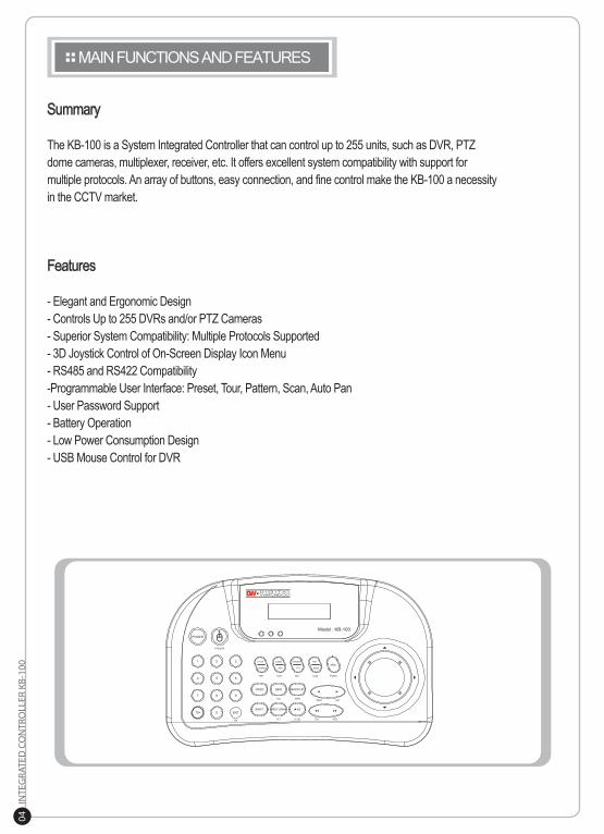
The KB-100 is a System Integrated Controller that can control up to 255 units, such as DVR, PTZ dome cameras, multiplexer, receiver, etc. It offers excellent system compatibility with support for multiple protocols. An array of buttons, easy connection, and fine control make the KB-100 a necessity in the CCTV market.
Features
- Elegant and Ergonomic Design- Controls Up to 255 DVRs and/or PTZ Cameras- Superior System Compatibility: Multiple Protocols Supported- 3D Joystick Control of On-Screen Display Icon Menu - RS485 and RS422 Compatibility -Programmable User Interface: Preset, Tour, Pattern, Scan, Auto Pan- User Password Support- Battery Operation - Low Power Consumption Design - USB Mouse Control for DVR
CONTROLLER & ACCESSORIES
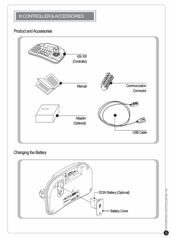
Product and Accessories
Changing the Battery
KB-100(Controller)
Manual
Adaptor(Optional)
CommunicationConnector
USB Cable
Battery Cover
DC9V Battery (Optional)
CONTROLLER BUTTON OVERVIEW
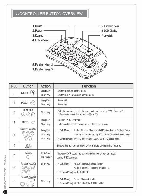
1. Mouse2. Power3. Keypad4. Enter / Select
5. Function Keys6. LCD Display7. Joystick
8. Function Keys (2)9. Function Keys (3)
Navigate DVR setup menu; switch channel display or mode; control PTZ camera
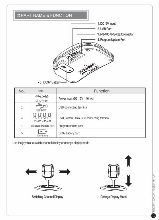
PART NAME & FUNCTION
1. DC12V Input2. USB Port3. RS-485 / RS-422 Connector4. Program Update Port
Use the joystick to switch channel display or change display mode.
Switching Channel Display Change Display Mode
CONNECTION
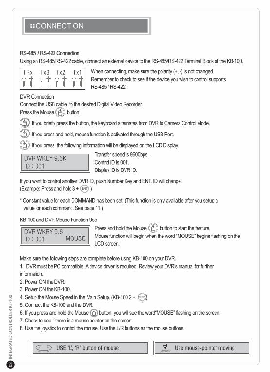
RS-485 / RS-422 ConnectionUsing an RS-485/RS-422 cable, connect an external device to the RS-485/RS-422 Terminal Block of the KB-100.
When connecting, make sure the polarity (+, -) is not changed. Remember to check to see if the device you wish to control supports RS-485 / RS-422.
DVR ConnectionConnect the USB cable to the desired Digital Video Recorder. Press the Mouse button.
If you briefly press the button, the keyboard alternates from DVR to Camera Control Mode.
If you press and hold, mouse function is activated through the USB Port.
If you press, the following information will be displayed on the LCD Display. Transfer speed is 9600bps.
Control ID is 001. Display ID is DVR ID.
If you want to control another DVR ID, push Number Key and ENT. ID will change. (Example: Press and hold 3 + .)
* Constant value for each COMMAND has been set. (This function is only available after you setup a value for each command. See page 11.)
KB-100 and DVR Mouse Function Use
Make sure the following steps are complete before using KB-100 on your DVR. 1. DVR must be PC compatible. A device driver is required. Review your DVR’s manual for further information. 2. Power ON the DVR. 3. Power ON the KB-100. 4. Setup the Mouse Speed in the Main Setup. (KB-100 2 + )5. Connect the KB-100 and the DVR. 6. If you press and hold the Mouse button, you will see the word“MOUSE” flashing on the screen. 7. Check to see if there is a mouse pointer on the screen. 8. Use the joystick to control the mouse. Use the L/R buttons as the mouse buttons.
Press and hold the Mouse button to start the feature. Mouse function will begin when the word “MOUSE” begins flashing on the LCD screen.
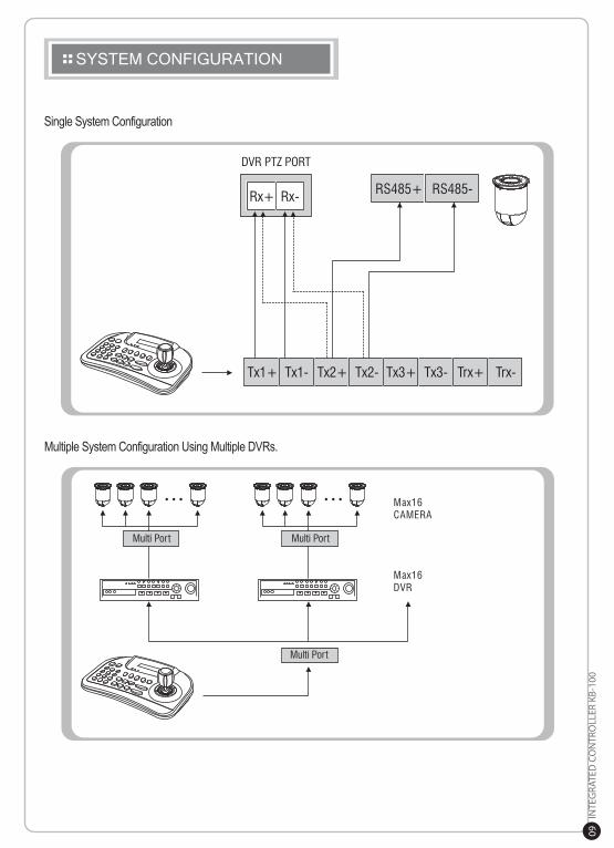
SYSTEM CONFIGURATION
Single System Configuration
Multiple System Configuration Using Multiple DVRs.
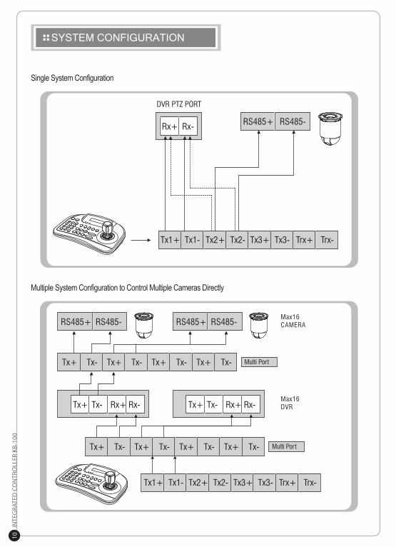
SYSTEM CONFIGURATION
Single System Configuration
Multiple System Configuration to Control Multiple Cameras Directly
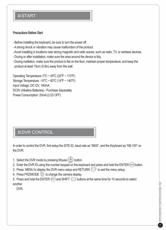
START
In order to control the DVR, first setup the SITE ID, baud rate as “9600”, and the Keyboard as “KB-100” on the DVR.
1. Select the DVR mode by pressing Mouse button.2. Enter the DVR ID using the number keypad on the keyboard and press and hold the ENTER button.3. Press MENU to display the DVR menu setup and RETURN to exit the menu setup. 4. Press FRZ/MODE to change the camera display. 5. Press and hold the ENTER and SHIFT buttons at the same time for 10 seconds to select another DVR.
DVR CONTROL
Precautions Before Start
- Before installing the keyboard, be sure to turn the power off. - A strong shock or vibration may cause malfunction of the product.- Avoid installing in locations near strong magnetic and radio waves, such as radio, TV, or wireless devices. - During or after installation, make sure the area around the device is tidy. - During instllation, make sure the product is flat on the floor, maintain proper temperature, and keep the product at least 15cm (5.9in) away from the wall.
Operating Temperature: 0oC ~ 45oC (32oF ~ 113oF).Storage Temperature: -10oC ~ 60oC (14oF ~ 140oF). Input Voltage: DC12V, 140mA DC9V (Alkaline Batteries) - Purchase SeparatelyPower Consumption: 20mA (LCD OFF)
CONTROLLER MAIN SETUP
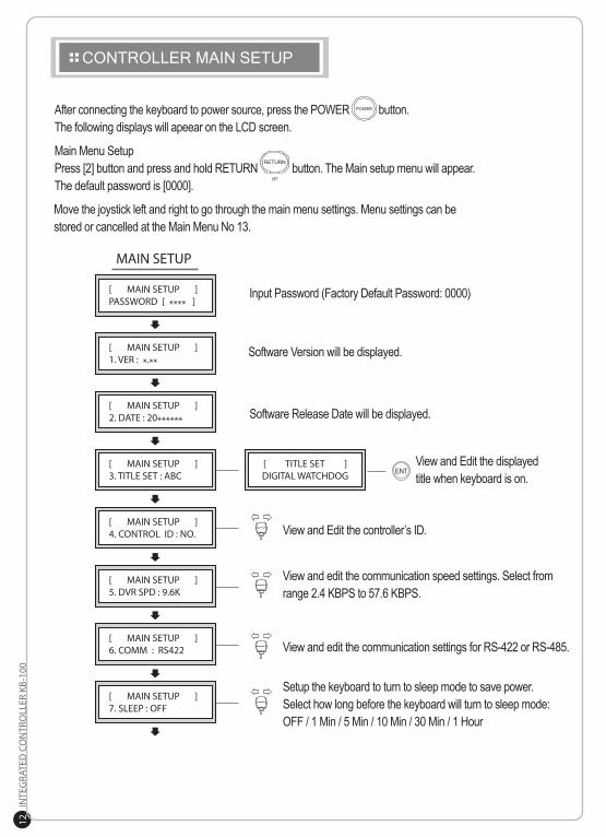
After connecting the keyboard to power source, press the POWER button. The following displays will apeear on the LCD screen.
Main Menu SetupPress [2] button and press and hold RETURN button. The Main setup menu will appear. The default password is [0000].
Move the joystick left and right to go through the main menu settings. Menu settings can be stored or cancelled at the Main Menu No 13.
Software Version will be displayed.
View and Edit the displayed title when keyboard is on.
View and Edit the controller’s ID.
View and edit the communication speed settings. Select from range 2.4 KBPS to 57.6 KBPS.
View and edit the communication settings for RS-422 or RS-485.
Setup the keyboard to turn to sleep mode to save power. Select how long before the keyboard will turn to sleep mode: OFF / 1 Min / 5 Min / 10 Min / 30 Min / 1 Hour
Software Release Date will be displayed.
Input Password (Factory Default Password: 0000)
CONTROLLER MAIN SETUP
Software Version will be displayed.
View and Edit the controller’s ID.
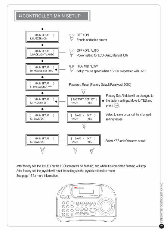
OFF / ONEnable or disable buzzer.
OFF / ON / AUTO Power setting for LCD (Auto, Manual, Off)
Password Reset (Factory Default Password: 0000)
HIG / MID / LOWSetup mouse speed when KB-100 is operated with DVR.
Select YES or NO to save or exit.
Select to save or cancel the changed setting values.
Factory Set: All data will be changed to the factory settings. Move to YES and press .
After factory set, the Tx LED on the LCD screen will be flashing, and when it is completed flashing will stop. After factory set, the joystick will reset the settings in the joystick calibration mode. See page 15 for more information.
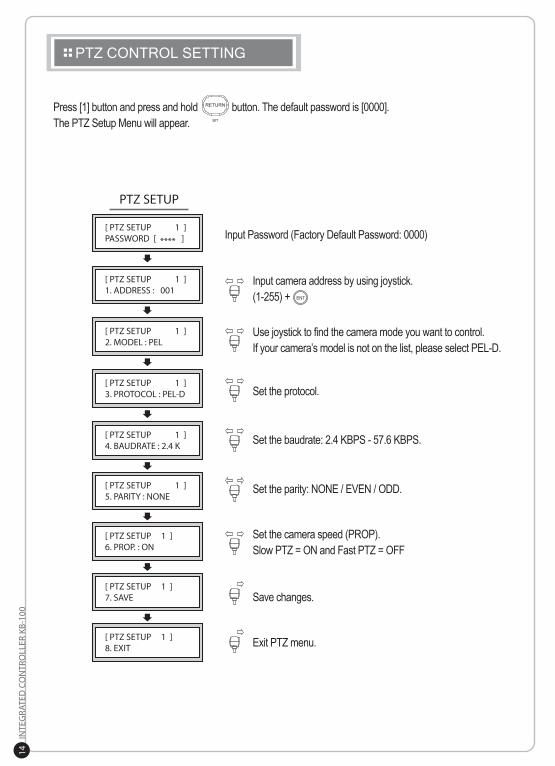
PTZ CONTROL SETTING
Press [1] button and press and hold button. The default password is [0000]. The PTZ Setup Menu will appear.
Input Password (Factory Default Password: 0000)
Input camera address by using joystick. (1-255) +
Use joystick to find the camera mode you want to control. If your camera’s model is not on the list, please select PEL-D.
Set the protocol.
Set the baudrate: 2.4 KBPS - 57.6 KBPS.
Set the parity: NONE / EVEN / ODD.
Set the camera speed (PROP). Slow PTZ = ON and Fast PTZ = OFF
Save changes.
Exit PTZ menu.
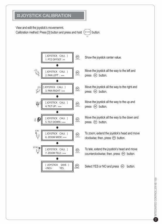
JOYSTICK CALIBRATION
Show the joystick center value.
Move the joystick all the way to the left andpress button.
View and edit the joystick’s movememnt. Calibration method: Press [3] button and press and hold button.
Move the joystick all the way to the right andpress button.
Move the joystick all the way to the up andpress button.
Move the joystick all the way to the down andpress button.
To zoom, extend the joystick’s head and move clockwise; then, press button.
Select YES or NO and press button.
To tele, extend the joystick’s head and move counterclockwise; then, press button.
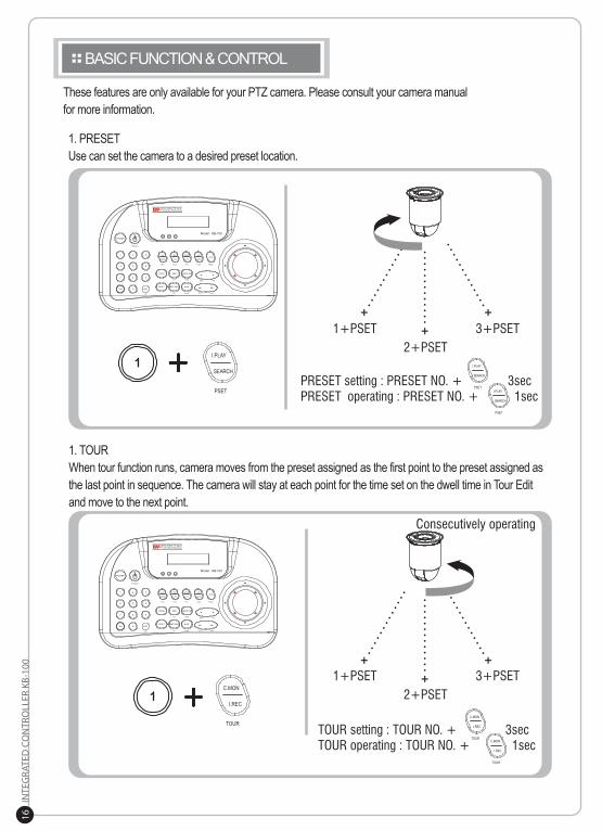
BASIC FUNCTION & CONTROL
These features are only available for your PTZ camera. Please consult your camera manual for more information.
1. PRESETUse can set the camera to a desired preset location.
1. TOURWhen tour function runs, camera moves from the preset assigned as the first point to the preset assigned as the last point in sequence. The camera will stay at each point for the time set on the dwell time in Tour Edit and move to the next point.
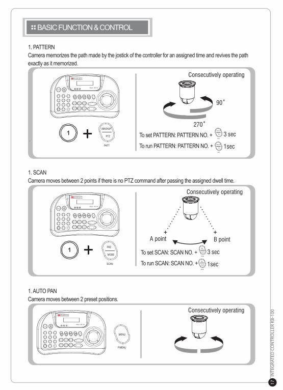
BASIC FUNCTION & CONTROL
1. PATTERNCamera memorizes the path made by the jostick of the controller for an assigned time and revives the path exactly as it memorized.
1. SCANCamera moves between 2 points if there is no PTZ command after passing the assigned dwell time.
1. AUTO PAN Camera moves between 2 preset positions.
To set SCAN: SCAN NO. +
To run SCAN: SCAN NO. +
To set PATTERN: PATTERN NO. +
To run PATTERN: PATTERN NO. +
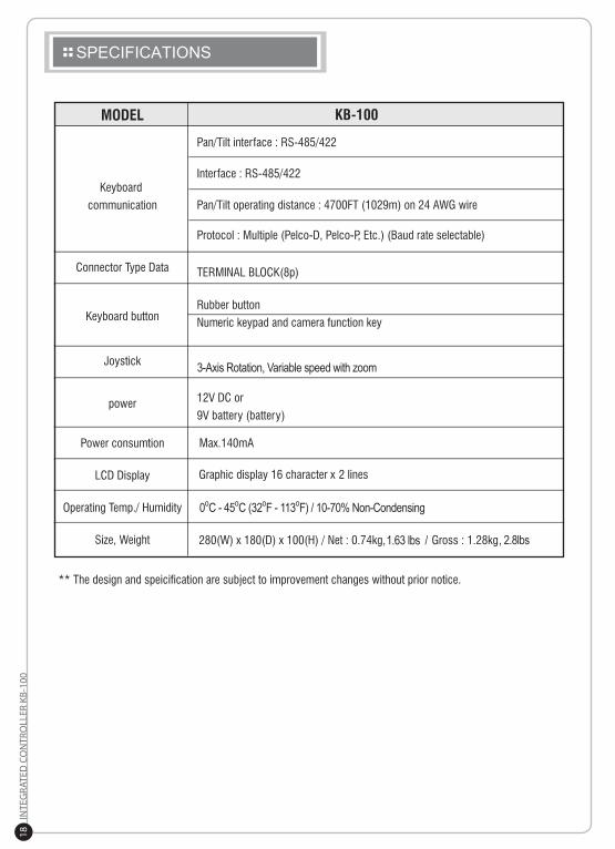
SPECIFICATIONS
3-Axis Rotation, Variable speed with zoom
0oC - 45oC (32oF - 113oF) / 10-70% Non-Condensing
, 2.8lbs1.63 lbs /
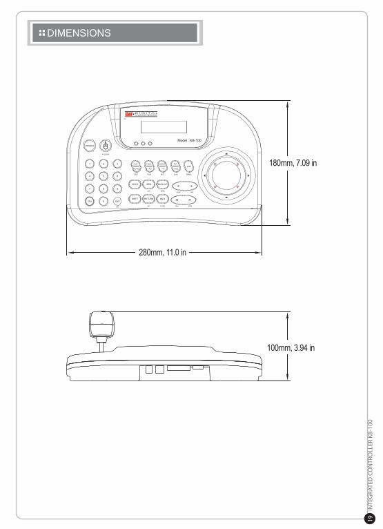
DIMENSIONS
180mm, 7.09 in
280mm, 11.0 in
100mm, 3.94 in
MEMO
MEMO


![DEPARTMENT OF JUSTICE [PDF 100 KB]](https://img.pdfslide.us/doc/110x75/58930c0c1a28abd6778b8a07/department-of-justice-pdf-100-kb.jpg)