Embed Size (px)
Citation preview
A Two-stage Method for Inverse Medium Scattering
Kazufumi Ito∗ Bangti Jin† Jun Zou‡
October 31, 2018
Abstract
We present a novel numerical method to the time-harmonic inverse medium scatteringproblem of recovering the refractive index from near-field scattered data. The approach con-sists of two stages, one pruning step of detecting the scatterer support, and one resolutionenhancing step with mixed regularization. The first step is strictly direct and of samplingtype, and faithfully detects the scatterer support. The second step is an innovative appli-cation of nonsmooth mixed regularization, and it accurately resolves the scatterer sizes aswell as intensities. The model is efficiently solved by a semi-smooth Newton-type method.Numerical results for two- and three-dimensional examples indicate that the approach isaccurate, computationally efficient, and robust with respect to data noise.Key words: inverse medium scattering problem, reconstruction algorithm, sampling method,mixed regularization, semi-smooth Newton method
1 Introduction
In this work we study the inverse medium scattering problem (IMSP) of determining the re-fractive index from near-field measurements for time-harmonic wave propagation [8]. Considera homogeneous background space Rd (d = 2, 3) that contains some inhomogeneous media oc-cupying a bounded domain Ω. Let uinc = eik x·d be an incident plane wave, with the incidentdirection d ∈ Sd−1 and the wave number k. Then the total field u induced by the inhomogeneousmedium scatterers satisfies the Helmholtz equation [8]
∆u+ k2 n2(x)u = 0, (1)
where the function n(x) is the refractive index, i.e., the ratio of the wave speed in the homoge-neous background to that in the concerned medium at location x. The model describes not onlytime-harmonic acoustic wave propagation, but also electromagnetic wave propagation in eitherthe transverse magnetic or transverse electric modes [16, Appendix].
Next we let η = (n2−1)k2, which combines the relative refractive index n2−1 with the wavenumber k. Clearly the coefficient η characterizes the material properties of the inhomogeneity
∗Department of Mathematics and Center for Research in Scientific Computation, North Carolina State Uni-versity, Raleigh, North Carolina ([email protected]).†Department of Mathematics and Institute for Applied Mathematics and Computational Science, Texas A&M
University, College Station, Texas 77843-3368, USA ([email protected]).‡Department of Mathematics, Chinese University of Hong Kong, Shatin, N.T., Hong Kong
1
arX
iv:1
205.
4277
v1 [
mat
h.N
A]
18
May
201
2
and is supported in the scatterer Ω ⊂ Rd. We denote by I = ηu the induced current, by G(x, y)the fundamental solution to the Helmholtz equation in the homogeneous background, i.e.,
G(x, y) =
i
4H1
0 (k |x− y|), d = 2,
1
4π
eik|x−y|
|x− y|, d = 3,
where the function H10 refers to Hankel function of the first kind and zeroth-order. Then we can
express the total field u as follows [8]
u = uinc +
∫ΩG(x, y)I(y) dy . (2)
By multiplying both sides of equation (2) by η, we arrive at the following integral equation ofthe second kind for the induced current I
I(x) = ηuinc + η
∫ΩG(x, y)I(y)dy. (3)
The reformulation (3) is numerically amenable since all computation is restricted to the scatterersupport Ω, which is much smaller than the whole space Rd. Hence, the complexity is also verylow. We will approximate the solution to (3) by the mid-point rule (cf. Appendix A).
Next we let us = u−uinc be the scattered field, which is measured on a closed curve/surfaceΓ enclosing the scatterers Ω. Then the IMSP is to retrieve the refractive index n2 or equivalentlythe coefficient η from (possibly very noisy) measurements of the scattered field us, correspondingto one or several incident fields. In the literature, a number of reconstruction techniques for theIMSP have been developed. These methods can be roughly divided into two groups: supportdetection and coefficient estimate. The former group (including MUSIC [10, 6], linear samplingmethod [7, 3] and factorization method [20] etc.) usually is of sampling type, and aims at detect-ing the scatterer support efficiently. The latter group generally relies on the idea of regularization(including Tikhonov regularization [2, 23], iterative regularization method [12, 1, 13], contrastsource inversion [27], subspace regularization [5] and propagation-backpropagation method [28]),and aims at retrieving a distributed estimate of the index function. These approaches generallyare more expensive, but their results may profile the inhomogeneities more precisely.
In this paper, we shall develop a novel two-stage numerical method for solving the IMSP. Thefirst step employs a direct sampling method, recently developed in [16], to detect the scatterersupport Ω stably and accurately. It is based on the following index function
Φ(xp) =|〈us, G(·, xp)〉L2(Γ)|
‖us‖L2(Γ)‖G(·, xp)‖L2(Γ)∀xp ∈ Ω, (4)
where Ω ⊃ Ω is a sampling domain. Numerically, the method is strictly direct and does not incurany linear matrix operations. The method can detect reliably the scatterer support Ω even inthe presence of a large amount of data noises [16]. In particular, a (much smaller) computationaldomain D ⊂ Ω can be determined from the index Φ, and furthermore the restriction Φ|D mayserve as a first approximation to the coefficient η.
The second step enhances the image resolution by a novel application of (nonsmooth) mixedregularization. With the approximation Φ|D from the sampling step at hand, equation (3) gives
2

an approximate induced current I as well as an approximate total field u. Then we seek aregularized solution η to the linearized scattering equation∫
DG(x, y) u(y) η(y) dy = us(x), (5)
by an innovative regularization incorporating both L1 and H1 penalties. The L1 penalty pro-motes the sparsity of the solution [25, 4, 11]. However, the estimate tends to be very spikywith the L1 penalty used alone. Meanwhile, the conventional H1 penalty can only yield globallysmooth but often overly diffusive profiles. In this work we shall propose a novel mixed model thatconsists of a suitable combination of the L1 and H1 penalties. As we will see, this mixed modelproduces well clustered and yet distributed solutions, thereby overcoming the aforementioneddrawbacks. It is the mixed model that enables us to obtain a clear and accurate reconstructionof the inclusions: The homogeneous background is vividly separated from the scatterers andboth support and intensity of the inclusions are accurately resolved.
Numerically, the L1 penalty term gives rise to a nonsmooth optimality condition, whichrenders its direct numerical treatment inconvenient. Fortunately, by using complementarityfunctions, the optimality condition reduces to a coupled nonlinear system for the sought-forcoefficient η and the Lagrangian multiplier, which is amenable to efficient numerical solution.We shall develop an efficient and stable semi-smooth Newton solver for the model via a primal-dual active-set strategy [18]. Overall, the direct sampling method is very cheap and reducesthe computational domain D in the mixed model (cf. (5)) significantly, which in turn makesthe semi-smooth Newton method for the mixed model very fast. Hence, the proposed inversescattering method is computationally very efficient.
The rest of the paper is structured as follows. In Section 2, we recall a novel direct samplingmethod for screening the scatterer support Ω, and derive thereby an initial guess to the coef-ficient η. Then in Section 3 we develop an enhancement technique based on the idea of mixedregularization, and an efficient semi-smooth Newton solver. Finally, we present numerical re-sults for two- and three-dimensional examples to demonstrate the accuracy and efficiency of theproposed inverse scattering method.
2 A direct sampling method
In this section, we describe a direct sampling method to determine the shape of the scatterers,recently derived in [16]. We only briefly recall the derivation, but refer the readers to [16] formore details. Consider a circular curve Γ (d = 2) or a spherical surface Γ (d = 3). Let G(x, xp)be the fundamental solution in the homogeneous background. Then using the definitions of thefundamental solutions G(x, xp) and G(x, xq) and Green’s second identity, we deduce
2i=(G(xp, xq)) =
∫Γ
[G(x, xq)
∂G(x, xp)
∂n−G(x, xp)
∂G(x, xq)
∂n
]ds, (6)
where the points xp, xq ∈ ΩΓ, the domain enclosed by the boundary Γ.Next we approximate the right hand side of identity (6) by means of the Sommerfeld radiation
condition for the Helmholtz equation, i.e.,
∂G(x, xp)
∂n= ikG(x, xp) + h.o.t..
3
Consequently, we arrive at the following approximate relation∫ΓG(x, xp)G(x, xq)ds ≈ k−1=(G(xp, xq)),
which is valid if the points xp and xq are not close to the boundary Γ.
Now, we consider a sampling domain Ω enclosing the scatterer support Ω. Upon dividing Ωinto small elements τj, we may approximate the integral in the scattering relation (2) by
us(x) =
∫ΩG(x, y)I(y)dy ≈
∑j
wj G(x, yj), (7)
where the weight wj is given by |τj |Ij with |τj | being the volume of the jth element τj . Therelation (7) is plausible if the induced current I is regular in each element and the elements τjare sufficiently fine. It also admits a nice physical interpretation: the scattered field us at anyfixed point x ∈ Γ is a weighted average of that due to point scatterers located at yj.
Combining the preceding two relations yields∫Γus(x)G(x, xp)ds ≈ k−1
∑j
wj=(G(yj , xp)). (8)
Hence, if the sampling point xp is close to some point scatterer yj , i.e., yj ∈ Ω, then G(yj , xp)is nearly singular and takes a very large value, contributing significantly to the sum in (8).Conversely, if the point xp is far away from all the physical point scatterers, then the sum willbe very small due to the decay property of G(yj , xp).
These facts lead us to the index function Φ(xp) in (4) for any xp in the sampling region Ω.In practice, if a point xp satisfies Φ(xp) ≈ 1, then it likely lies within the support; whereas ifΦ(xp) ≈ 0, then the point xp most probably lies outside the support. Hence it serves as an
indicator of the scatterer support. Consequently, we can determine a domain D ⊂ Ω as oneapproximate scatterer support, and moreover, the restriction Φ|D of the index Φ to the domainD may be regarded as a first approximation to the sought-for coefficient η. The subdomain Dmay be chosen as D = x ∈ Ω : Φ(x) ≥ µmax
x∈ΩΦ(x) with µ being a cut-off value, i.e., the
union of elements whose index values are not less than a specified fraction of the largest indexvalue over the sampling region Ω. This determination of subdomain D will be adopted in ournumerical experiments.
This method is of sampling type (cf. [22] for an overview of existing sampling methods), andits flavor closely resembles multiple signal classification [24, 6, 10] and linear sampling method[7, 20]. However, unlike these existing techniques, it works with a few (e.g., one or two) incidentwaves, is highly tolerant with respect to noise, and involves only computing inner products withfundamental solutions rather than expensive matrix operations as in the other two techniques.The robustness of Φ is attributed to the fact that the (high-frequency) noise is roughly orthogonalto the (smooth) fundamental solutions.
3 Mixed regularization
The direct sampling method in Section 2 extracts an accurate estimateD to the scatterer supportΩ as well as a reasonable initial guess to the medium coefficient η, i.e., Φ|D. In this part we
4
refine the approximation Φ|D by exploiting the idea of nonsmooth mixed regularization. Giventhe approximation Φ|D, we can compute the induced current I via (3) for each incident wave andthe corresponding total field u on the domain D from (2). By substituting the approximation uinto equation (2), we arrive at the following linearized problem∫
DG(x, y)u(y)η(y)dy = us(x) , x ∈ Γ.
It is convenient to introduce a linear integral operator K : L2(D) 7→ L2(Γ) defined by
(Kη)(x) =
∫DG(x, y)u(y) η(y) dy. (9)
We observe that the kernel G(x, y)u(y) is smooth due to the analyticity of fundamentalfunctions G(x, y) away from the singularities and standard Sobolev smoothness of the total fieldu(y) (following from elliptic regularity theory [8]). Hence, the linear operatorK : L2(D) 7→ L2(Γ)is compact. As a consequence, the linearized problem (9) is ill-posed in the sense that smallperturbations in the data can lead to huge deviations in the solution, according to the classicalinverse theory [26], which is reminiscent of the severe ill-posedness of the IMSP, and its stableand accurate numerical solution calls for regularization techniques.
We determine an enhanced estimate of the coefficient η from the linearized problem (9) bysolving the following variational problem:
min1
2
∫Γ|Kη − us|2ds+ α
∫D|η|dx+
β
2
∫D|∇η|2dx. (10)
In comparison with more conventional regularization techniques, the most salient feature of themodel (10) lies in two penalty terms: it contains both the L1 penalty and the H1 penalty, whichexert drastically different a priori knowledge of the sought-for solution. The scalars α and β areregularization parameters controlling the strength of respective regularization.
This variational problem (10) allows us to determine a coefficient η which is distributedyet clustered, i.e., exhibiting a clear groupwise sparsity structure in the canonical pixel basis.This a priori knowledge is plausible for localized inclusions/inhomogeneities in a homogeneousbackground. The model (10) is derived from the following widely accepted observations. The L1
penalty promotes the sparsity of the solution [25, 4, 11], i.e., the solution is very much localized.Hence, the estimated background is homogeneous. However, if the L1 penalty is used alone, thesolution tends to be very spiky and may miss numerous physically relevant pixels in the sought-for groups. That is, the desirable groupwise structure is not preserved. Meanwhile, the moreconventional H1 penalty [26] yields a globally smooth profile, but the solution is often overlydiffusive. Consequently, the overall structure stands out clearly, but the retrieved backgroundis very blurry, which may lead to erroneous diagnosis of the number of the inclusions and theirsizes. In order to preserve simultaneously these distinct features of the sought-for coefficient, i.e.,sparsely distributed groupwise structures in a homogeneous background, a natural idea wouldbe to combine the L1 penalty with the H1 penalty, in the hope of retaining the strengths of bothmodels. As we shall see below, the idea does work very well, and the model is very effective forenhancing the resolution of the estimate to the coefficient η.
The general idea of mixed regularization, i.e., using multiple penalties, has proved very effec-tive in promoting several distinct features simultaneously. This general idea has been pursued
5
in the imaging community [17, 21]. However, to the best of our knowledge, the model (10) hasnot been explored in the literature, let alone its efficient and accurate numerical treatment. Adetailed mathematical analysis of the model (10) is beyond the scope of the present paper. Werefer interested readers to [14] for some preliminary results on mixed regularization and to [19]for a related model (elastic-net).
To fully explore the potentials of the model (10), an efficient and accurate solver is required.We shall develop a semi-smooth Newton type method, which allows extracting very detailedfeatures of the solutions to the model (10). The starting point of the algorithm is the necessaryoptimality condition of the variational problem (10), which reads
K∗Kη − β∆η −K∗us ∈ −α∂ψ(η), (11)
where ψ(η) = ‖η‖L1 and the subdifferential ∂ψ(η) [18] is the set-valued signum function, whichis defined pointwise as
∂ψ(η)(x) =
1, if η(x) > 0,[−1, 1 ], if η(x) = 0,−1, if η(x) < 0.
Due to the convexity of the functional, the relation (11) is also a sufficient condition. Henceit suffices to solve the inclusion (11), for which there are several different ways, e.g., iterative softshrinkage [9, 29], augmented Lagrangian method/alternating direction method or semi-smoothNewton method [18]. We shall develop a (new) semi-smooth Newton method to efficiently solvethe inclusion (11). To this end, we first recall the complementarity condition [18]
λ =λ+ cη
max(1, |λ+ c η|)(12)
for any c > 0, which will be fixed at a constant in the implementation, and λ serves as a Lagrangemultiplier. It can be directly verified by pointwise inspection that the complementarity condition(12) is equivalent to the inclusion λ ∈ ∂ψ(η) (cf. [18]). With the help of the complementaritycondition (12), we arrive at the following equivalent nonlinear system in the primal variable ηand dual variable λ:
K∗Kη − β∆η −K∗us + αλ = 0,
λ− λ+ cη
max(1, |λ+ c η|)= 0.
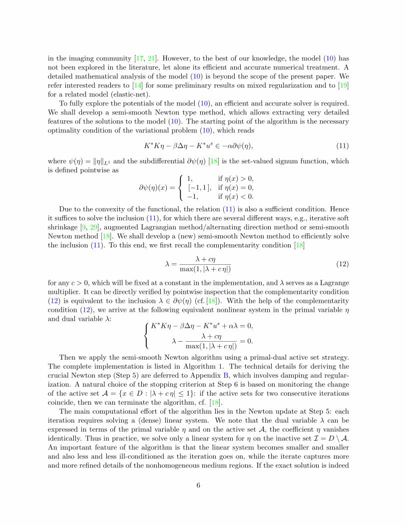
Then we apply the semi-smooth Newton algorithm using a primal-dual active set strategy.The complete implementation is listed in Algorithm 1. The technical details for deriving thecrucial Newton step (Step 5) are deferred to Appendix B, which involves damping and regular-ization. A natural choice of the stopping criterion at Step 6 is based on monitoring the changeof the active set A = x ∈ D : |λ + c η| ≤ 1: if the active sets for two consecutive iterationscoincide, then we can terminate the algorithm, cf. [18].
The main computational effort of the algorithm lies in the Newton update at Step 5: eachiteration requires solving a (dense) linear system. We note that the dual variable λ can beexpressed in terms of the primal variable η and on the active set A, the coefficient η vanishesidentically. Thus in practice, we solve only a linear system for η on the inactive set I = D \ A.An important feature of the algorithm is that the linear system becomes smaller and smallerand also less and less ill-conditioned as the iteration goes on, while the iterate captures moreand more refined details of the nonhomogeneous medium regions. If the exact solution is indeed
6
Algorithm 1 Primal-dual active set method
1: Initialize η0 and λ0, and set c > 0 and k = 0.2: for k = 0, . . . ,K do3: Set the active set Ak and inactive set Ik respectively by
Ak = x ∈ D : |λk + c ηk| ≤ 1,Ik = x ∈ D : |λk + c ηk| > 1.
4: Compute a and b by
a =λk
max(|λk|, 1)and b =
λk + c ηk
|λk + c ηk|,
and set dk = |λk + cηk| and F k = abt.5: Solve for (ηk+1, λk+1) from the system
K∗Kηk+1 − β∆ηk+1 −K∗us + αλk+1 = 0 on Ik,
λk+1 − c 1
dk − 1(I − F k)ηk+1 − λk
max(|λk|, 1)= 0,
ηk+1 = 0 on Ak.
6: Check the stopping criterion.7: end for8: output approximation ηK .
sparse (many zero entries), then the system size, i.e., |I|, usually shrinks quickly as the iterationproceeds. The numerical experiments indicate that the convergence of the algorithm is rathersteady and fast.
4 Numerical experiments
In this part, we present numerical results for several two- and three-dimensional examples toshowcase the proposed two-stage inverse scattering method, for both exact and noisy data. Thewave number k is fixed at 2π, and the wavelength is set to λ = 1. The exact scattered field us isobtained by first solving the integral equation (3) for the induced current I and then substitutingthe current I into the integral representation (2). Here the integral equation (3) is discretizedby a mid-point rule; see Appendix A for details. The noisy scattered data usδ are generatedpointwise by the formula
usδ(x) = us(x) + εζ maxx∈Γ|us(x)|,
where ε refers to the relative noise level, and both the real and imaginary parts of the noiseζ = ζ(x) follow the standard Gaussian distribution. The index Φ, its restriction Φ|D and theenhanced approximation η by the mixed model will be displayed. As is mentioned in Section 2,we choose the subdomain D (approximate scatterer support) based on the formula D = x ∈
7

(a) true scatterer (b) index Φ (c) index Φ|D (d) sparse recon.
Figure 1: Numerical results for Example 1(a): (a) true scatterer, (b) index Φ, (c) index Φ|D(restriction to the subdomain D) and (d) sparse reconstruction. The first and second rows referto exact data and the data with 20% noise, respectively.
Ω : Φ(x) ≥ µmaxx∈Ω
Φ(x), where the cut-off value µ is taken in the range (0.5, 0.7). The choiceof the cutoff value µ affects directly the size of the domain D, but does not cause much effectson the reconstructions.
Like in any regularization technique, an appropriate choice of regularization parameters(α, β) in the mixed model (10) is crucial for the success of the proposed imaging algorithm.There have been a number of choice rules [15] for one single parameter, but very little is knownabout the mixed model. We shall choose the pair (α, β) in a trial and error manner, which sufficesour goal of illustrating the significant potentials of the mixed model for inverse scattering. InAlgorithm 1, the parameter c is set to 50, and both η0 and λ0 are initialized to zero. Themaximum number K of Newton iterations is 50. In all the experiments, the convergence ofthe algorithm is achieved within about 10 iterations. All the computations were performed onMATLAB 7.12.0 (R2011a) on a dual-core desktop computer with 2GB RAM.
4.1 Two-dimensional examples
Unless otherwise specified, one incident direction d is employed for two-dimensional problems,and it is fixed at 1√
2(1, 1)T. The scattered field us is measured at 30 points uniformly distributed
on a circle of radius 5. The sampling domain Ω is fixed at [−2, 2]2, which is divided into a uniformmesh consisting of small squares of width h = 0.01. The subdomain D for the integral equation(9) is divided into a coarser uniform mesh consisting of small squares of width 0.02.
Our first example illustrates the method for two separate scatterers.
Example 1. We consider two separate square scatterers in the following two scenarios
(a) The scatterers are of width 0.2 and centered at (−0.8,−0.7) and (0.3, 0.9), respectively,and the coefficient η in both region is 1.
8
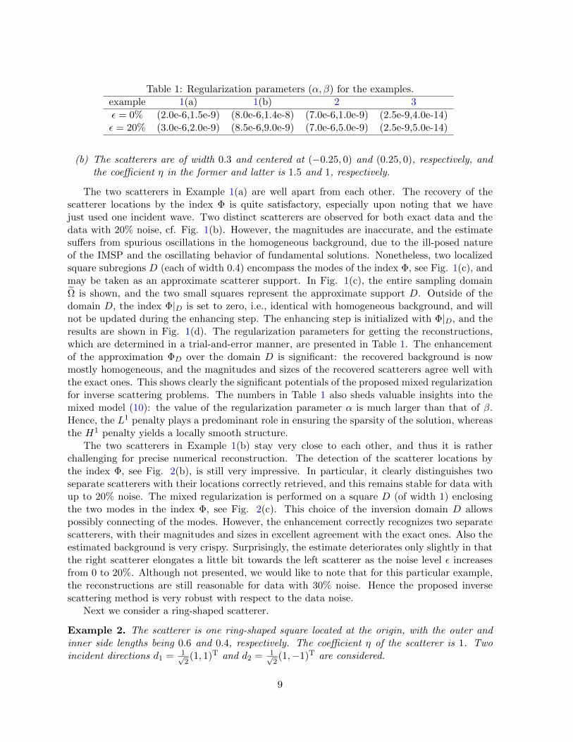
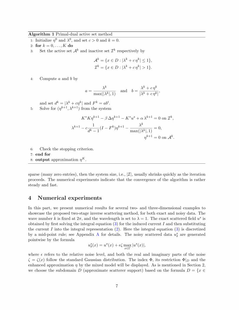
Table 1: Regularization parameters (α, β) for the examples.example 1(a) 1(b) 2 3
ε = 0% (2.0e-6,1.5e-9) (8.0e-6,1.4e-8) (7.0e-6,1.0e-9) (2.5e-9,4.0e-14)ε = 20% (3.0e-6,2.0e-9) (8.5e-6,9.0e-9) (7.0e-6,5.0e-9) (2.5e-9,5.0e-14)
(b) The scatterers are of width 0.3 and centered at (−0.25, 0) and (0.25, 0), respectively, andthe coefficient η in the former and latter is 1.5 and 1, respectively.
The two scatterers in Example 1(a) are well apart from each other. The recovery of thescatterer locations by the index Φ is quite satisfactory, especially upon noting that we havejust used one incident wave. Two distinct scatterers are observed for both exact data and thedata with 20% noise, cf. Fig. 1(b). However, the magnitudes are inaccurate, and the estimatesuffers from spurious oscillations in the homogeneous background, due to the ill-posed natureof the IMSP and the oscillating behavior of fundamental solutions. Nonetheless, two localizedsquare subregions D (each of width 0.4) encompass the modes of the index Φ, see Fig. 1(c), andmay be taken as an approximate scatterer support. In Fig. 1(c), the entire sampling domainΩ is shown, and the two small squares represent the approximate support D. Outside of thedomain D, the index Φ|D is set to zero, i.e., identical with homogeneous background, and willnot be updated during the enhancing step. The enhancing step is initialized with Φ|D, and theresults are shown in Fig. 1(d). The regularization parameters for getting the reconstructions,which are determined in a trial-and-error manner, are presented in Table 1. The enhancementof the approximation ΦD over the domain D is significant: the recovered background is nowmostly homogeneous, and the magnitudes and sizes of the recovered scatterers agree well withthe exact ones. This shows clearly the significant potentials of the proposed mixed regularizationfor inverse scattering problems. The numbers in Table 1 also sheds valuable insights into themixed model (10): the value of the regularization parameter α is much larger than that of β.Hence, the L1 penalty plays a predominant role in ensuring the sparsity of the solution, whereasthe H1 penalty yields a locally smooth structure.
The two scatterers in Example 1(b) stay very close to each other, and thus it is ratherchallenging for precise numerical reconstruction. The detection of the scatterer locations bythe index Φ, see Fig. 2(b), is still very impressive. In particular, it clearly distinguishes twoseparate scatterers with their locations correctly retrieved, and this remains stable for data withup to 20% noise. The mixed regularization is performed on a square D (of width 1) enclosingthe two modes in the index Φ, see Fig. 2(c). This choice of the inversion domain D allowspossibly connecting of the modes. However, the enhancement correctly recognizes two separatescatterers, with their magnitudes and sizes in excellent agreement with the exact ones. Also theestimated background is very crispy. Surprisingly, the estimate deteriorates only slightly in thatthe right scatterer elongates a little bit towards the left scatterer as the noise level ε increasesfrom 0 to 20%. Although not presented, we would like to note that for this particular example,the reconstructions are still reasonable for data with 30% noise. Hence the proposed inversescattering method is very robust with respect to the data noise.
Next we consider a ring-shaped scatterer.
Example 2. The scatterer is one ring-shaped square located at the origin, with the outer andinner side lengths being 0.6 and 0.4, respectively. The coefficient η of the scatterer is 1. Twoincident directions d1 = 1√
2(1, 1)T and d2 = 1√
2(1,−1)T are considered.
9
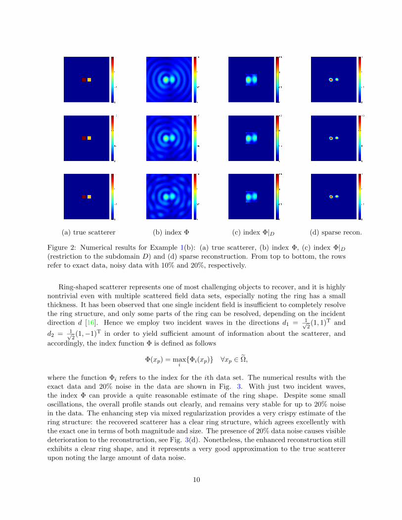
(a) true scatterer (b) index Φ (c) index Φ|D (d) sparse recon.
Figure 2: Numerical results for Example 1(b): (a) true scatterer, (b) index Φ, (c) index Φ|D(restriction to the subdomain D) and (d) sparse reconstruction. From top to bottom, the rowsrefer to exact data, noisy data with 10% and 20%, respectively.
Ring-shaped scatterer represents one of most challenging objects to recover, and it is highlynontrivial even with multiple scattered field data sets, especially noting the ring has a smallthickness. It has been observed that one single incident field is insufficient to completely resolvethe ring structure, and only some parts of the ring can be resolved, depending on the incidentdirection d [16]. Hence we employ two incident waves in the directions d1 = 1√
2(1, 1)T and
d2 = 1√2(1,−1)T in order to yield sufficient amount of information about the scatterer, and
accordingly, the index function Φ is defined as follows
Φ(xp) = maxiΦi(xp) ∀xp ∈ Ω,
where the function Φi refers to the index for the ith data set. The numerical results with theexact data and 20% noise in the data are shown in Fig. 3. With just two incident waves,the index Φ can provide a quite reasonable estimate of the ring shape. Despite some smalloscillations, the overall profile stands out clearly, and remains very stable for up to 20% noisein the data. The enhancing step via mixed regularization provides a very crispy estimate of thering structure: the recovered scatterer has a clear ring structure, which agrees excellently withthe exact one in terms of both magnitude and size. The presence of 20% data noise causes visibledeterioration to the reconstruction, see Fig. 3(d). Nonetheless, the enhanced reconstruction stillexhibits a clear ring shape, and it represents a very good approximation to the true scattererupon noting the large amount of data noise.
10

(a) true scatterer (b) index Φ (c) index Φ|D (d) sparse recon.
Figure 3: Numerical results for Example 2: (a) true scatterer, (b) index Φ, (c) index Φ|D(restriction to the subdomain D) and (d) sparse reconstruction. The first and second rows referto exact data and the data with 20% noise, respectively.
4.2 Three-dimensional example
Our last example shows the feasibility of the method for three-dimensional problems.
Example 3. We consider two cubic scatterers of width 0.1 centered at (0.35, 0.15, 0.15) and(−0.35, 0.15, 0.15), respectively. One single incident field with direction d = 1√
3(1, 1, 1)T is used,
and the coefficient η of the scatterers is taken to be 1.
The scattered field us is measured at 600 points uniformly distributed on the surface Γ of acubic of width 5, (i.e., 10 points in each direction). To simulate the scattered field data, we takethe sampling domain Ω to be the cubic [−1, 1]3, which is divided into a uniform mesh consistingof small cubes of width h = 0.01. The inversion domain D for the integral equation (9) is dividedinto a coarser mesh consisting of small cubes of width 0.03.
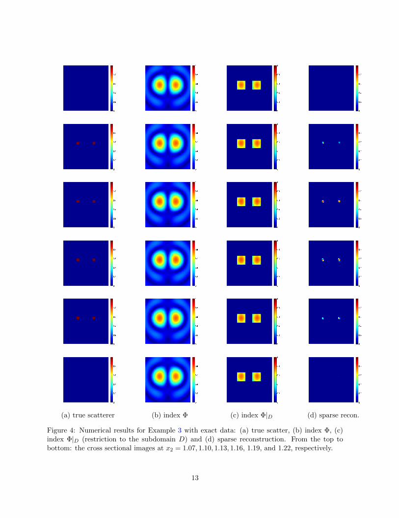
The numerical results for Example 3 with exact data are shown in Fig. 4(b), where each rowrepresents a cross-sectional image along the second coordinate axis x2. The scatterer supportestimated by the index Φ agrees reasonably with the exact one, and away from the boundaryof the true scatterers, the magnitude of Φ decreases quickly. However, the reconstructed profileis slightly diffusive in comparison with the exact one, which is reminiscent of the decay prop-erty of fundamental solutions. The nonsmooth mixed regularization (10) is carried out on twocubic subregions (of width 0.36λ), cf. Fig. 4(c). Like before, a significant improvement in theresolution is observed: the sparse estimate is much more localized in comparison with the indexΦ, and also the magnitude is close to the exact one; see Fig. 4(d). The presence of 20% datanoise does not worsen much the index Φ and the sparse reconstruction, cf. Fig. 5. Hence thereconstruction algorithm is highly tolerant with respect to data noise.
Lastly, we briefly comment on the computational efficiency of the overall procedure. Thefirst step with the index involves only computing inner products and is embarrassingly cheapand easily parallelized. The accuracy of the support detection is quite satisfactory, and thus alarge portion of the sampling domain Ω can be pruned from inversion, i.e., |D| |Ω|. Hence,
11
the enhancement via mixed regularization is also rather efficient.
5 Concluding remarks
We have presented a novel two-stage inverse scattering method for the inverse medium scatteringproblem of recovering the refractive index from near-field scattered data. The efficiency andaccuracy of the method stem from accurate support detection by the sampling strategy andgroup sparsity-promoting of the mixed regularization technique. The former is computationallyvery efficient, and reduces greatly the computational domain for the more expensive inversionvia nonsmooth mixed regularization, while the latter achieves an enhanced resolution with themagnitudes and sizes comparable with the exact ones. The numerical results for two- andthree-dimensional examples clearly confirm these observations.
These promising experimental results raise a number of interesting questions for furtherstudies. First, the potentials of mixed regularization have been clearly demonstrated. It is ofgreat interest to shed theoretical insights into the model as well as to design efficient acceler-ation strategies, which for three-dimensional problems remains very challenging. Some partialtheoretical results can be found in [14]. Also of much practical relevance is an automated choiceof regularization parameters. Second, the reconstructions were obtained with the linearizedmodel, which represents only an approximation to the genuine nonlinear IMSP model. It wouldbe interesting to justify the excellent performance of the linearization procedure. Third, the ro-bustness of the approach to noise is outstanding when compared with more conventional inversescattering algorithms, especially noting the limited data for inversion. The mechanism of therobustness is not yet clear.
Acknowledgements
The work of BJ is supported by Award No. KUS-C1-016-04, made by King Abdullah Universityof Science and Technology (KAUST), and that of JZ is substantially supported by Hong KongRGC grants (projects 405110 and 404611).
A Numerical method for forward scattering
We denote by J the index set of grid points of a uniformly distributed mesh with a mesh sizeh > 0 and consider square cells
Bj = Bj1,j2 = (x1j1 , x
2j2) + [−h
2 ,h2 ]× [h2 ,
h2 ]
for every tuple j = (j1, j2) belonging to the index set J. Assume that the domain ∪j∈JBj containsthe scatterer support Ω. We use the mid-point quadrature rule to evaluate the operator K, andhence the integral (3) is approximated by
Ik − ηk∑j∈J
Gk,jIjh2 = ηk u
inc(xk)
12
(a) true scatterer (b) index Φ (c) index Φ|D (d) sparse recon.
Figure 4: Numerical results for Example 3 with exact data: (a) true scatter, (b) index Φ, (c)index Φ|D (restriction to the subdomain D) and (d) sparse reconstruction. From the top tobottom: the cross sectional images at x2 = 1.07, 1.10, 1.13, 1.16, 1.19, and 1.22, respectively.
13
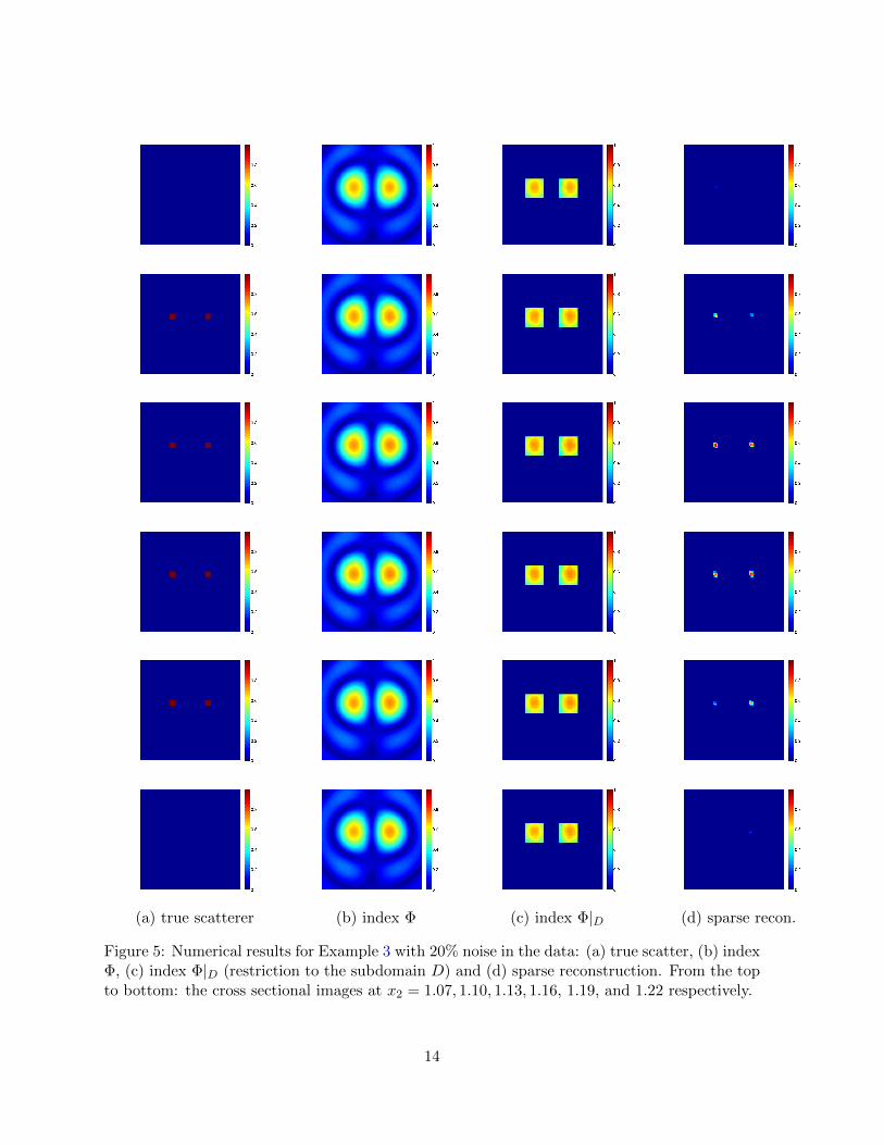
(a) true scatterer (b) index Φ (c) index Φ|D (d) sparse recon.
Figure 5: Numerical results for Example 3 with 20% noise in the data: (a) true scatter, (b) indexΦ, (c) index Φ|D (restriction to the subdomain D) and (d) sparse reconstruction. From the topto bottom: the cross sectional images at x2 = 1.07, 1.10, 1.13, 1.16, 1.19, and 1.22 respectively.
14

where Ik = I(xk) and ηk = η(xk), and the off-diagonal entries Gk,j and the diagonal entries Gk,kare given by Gk,j = G(xk, xj) and
Gk,k =1
h2
∫(−h2 ,
h2 )2
G(x, 0)dx,
respectively. The diagonal entries can be accurately computed by tensor-product Gaussianquadrature rules. The resulting system can be solved using standard numerical solvers, e.g.,Gaussian elimination, if the cardinality of the index set J is medium, and iterative solvers likeGMRES. The extension of the procedure to 3D problems is straightforward.
B Semi-smooth Newton method
In this part, we derive a semi-smooth Newton method for minimizing (10). The optimalitycondition of the variational problem reads
K∗Kη + αλ− β∆η −K∗us = 0,
λ− λ+ cη
max(1, |λ+ cη|)= 0,
where λ is the Lagrange multiplier (dual variable). The second line, the complementarity func-tion, equivalently expresses the inclusion λ ∈ ∂‖η‖L1 , which can be checked directly by pointwiseinspection. Thereby, we effectively transforms the inclusion (11) into a numerically amenablenonlinear system. It follows directly from the complementarity relation
λ =λ+ cη
max(1, |λ+ cη|)(13)
that on the active set A = x ∈ D : |λ + cη|(x) ≤ 1, η vanishes identically. Otherwise, boththe dual variable λ and the primal variable η need to be solved. We shall solve the system by asemi-smooth Newton method [18]. First observe that the Newton step (with the increments forλ and η denoted by δλ and δη, respectively) applied to the following reformulation of equation(13) (on the set I = D \ A)
λ|λ+ cη| − λ+ cη = 0
is given by
|λ+ cη|δλ+ λλ+ cη
|λ+ cη|[δλ+ cδη]− (δλ+ cδη) + λ|λ+ cη| − (λ+ cη) = 0,
or equivalently with the notation λ+ = λ+ δλ and η+ = η + δη, we have
λ+|λ+ cη|+ λλ+ cη
|λ+ cη|[λ+ + cη+] = λ|λ+ cη|+ [λ+ + cη+].
Next we apply the idea of damping and regularization to the equation and thus get
λ+|λ+ cη|+ θ[λ+ + cη+]λ+ cη
|λ+ cη|λ
max(|λ|, 1)= [λ+ + cη+] + θ|λ+ cη| λ
max(|λ|, 1).
15
Here, the purpose of the regularization step λmax(|λ|,1) is to automatically constrain the dual
variable λ to [−1, 1]. The damping factor θ is automatically selected to achieve the stability. Tothis end, we let d = |λ+ cη|, η = d− 1, a = λ
max(|λ|,1) , and b = λ+cη|λ+cη| . We arrive at
λ+(η + 1) + θ[λ+ + cη+]ab = [λ+ + cη+] + θad.
Thus we have
λ+ =1
η + θab[1− θab]cη+ +
θd
η + θaba
To arrive at a simple iteration scheme, we set θdη+θab = 1, i.e., θ = d−1
d−ab ≤ 1. Consequently, weobtain a simple iteration
λ+ =1− abd− 1
cη+ +λ
max(|λ|, 1),
where we have used the relation 1−θabη+θab = 1−ab
d−1 . Substituting this into the first equation gives
K∗Kη+ + αc1− abd− 1
η+ − β∆η+ = K∗us − α λ
max(|λ|, 1). (14)
We note that one only needs to solve equation (14) on the inactive set I, since on the activeset A, there always holds η+ = 0. This has an enormous computational consequence: the sizeof the linear system in (14) can be very small if |I| is small, i.e., the solution is sparse. Thislast relation shows also clearly the sparsity of the solution, and this provides a crispy estimateof the background. Upon obtaining the solution η+, one can update λ+ on the sets I and Aaccording to the second and the first equation, respectively. Lastly, we would like to remark onthe consistency of the scheme: if the sequence generated by the semi-smooth Newton methodconverges, then the limit satisfies the complementarity relation (13) as desired.
References
[1] A. B. Bakushinsky and K. A. I. Kokurin, M Yu. On stable iterative methods of gradienttype for the inverse medium scattering problem. Inv. Probl. Sci. Eng., 13(3):203–218, 2005.
[2] G. Bao and P. Li. Inverse medium scattering for the Helmholtz equation at fixed frequency.Inverse Problems, 21(5):1621–1641, 2005.
[3] F. Cakoni, D. Colton, and P. Monk. The Linear Sampling Method in Inverse Electromag-netic Scattering. SIAM, 2011.
[4] E. J. Candes, J. Romberg, and T. Tao. Robust uncertainty principles: exact signal re-construction from highly incomplete frequency information. IEEE Trans. Inf. Theory,52(2):489–509, 2006.
[5] X. Chen and Y. Zhong. MUSIC electromagnetic imaging with enhanced resolution for smallinclusions. Inverse Problems, 25(1):015008, 12, 2009.
[6] M. Cheney. The linear sampling method and the MUSIC algorithm. Inverse Problems,17(4):591–595, 2001.
16
[7] D. Colton and A. Kirsch. A simple method for solving inverse scattering problems in theresonance region. Inverse Problems, 12(4):383–393, 1996.
[8] D. Colton and R. Kress. Inverse Acoustic and Electromagnetic Scattering Theory. Springer-Verlag, Berlin, 2 edition, 1998.
[9] I. Daubechies, M. Defrise, and C. De Mol. An iterative thresholding algorithm for linearinverse problems with a sparsity constraint. Comm. Pure Appl. Math., 57(11):1413–1457,2004.
[10] A. J. Devaney. Super-resolution processing of multi-static data using time-reversal andmusic. available at http://www.ece.neu.edu/faculty/devaney/preprints/paper02n_
00.pdf, 1999.
[11] D. L. Donoho. Compressed sensing. IEEE Trans. Inf. Theory, 52(4):1289–1306, 2006.
[12] T. Hohage. On the numerical solution of a three-dimensional inverse medium scatteringproblem. Inverse Problems, 17(6):1743–1763, 2001.
[13] T. Hohage. Fast numerical solution of the electromagnetic medium scattering problem andapplications to the inverse problem. J. Comput. Phys., 214(1):224–238, 2006.
[14] K. Ito, B. Jin, and T. Takeuchi. Multi-parameter Tikhonov regularization. Methods Appl.Anal., 18(1):31–46, 2011.
[15] K. Ito, B. Jin, and T. Takeuchi. A regularization parameter for nonsmooth Tikhonovregularization. SIAM J. Sci. Comput., 33(3):1415–1438, 2011.
[16] K. Ito, B. Jin, and J. Zou. A direct sampling method to inverse medium scattering problem,2012.
[17] K. Ito and K. Kunisch. BV-type regularization methods for convoluted objects with edge,flat and grey scales. Inverse Problems, 16(4):909–928, 2000.
[18] K. Ito and K. Kunisch. Lagrange Multiplier Approach to Variational Problems and Appli-cations. SIAM, Philadelphia, PA, 2008.
[19] B. Jin, D. A. Lorenz, and S. Schiffler. Elastic-net regularization: error estimates and activeset methods. Inverse Problems, 25(11):115022 (26pp), 2009.
[20] A. Kirsch. Characterization of the shape of a scattering obstacle using the spectral data ofthe far field operator. Inverse Problems, 14(6):1489–1512, 1998.
[21] Y. Lu, L. Shen, and Y. Xu. Multi-parameter regularization methods for high-resolutionimage reconstruction with displacement errors. IEEE Trans. Circ. Syst. I: Reg. Pap.,54(8):1788–1799, 2007.
[22] R. Potthast. A survey on sampling and probe methods for inverse problems. InverseProblems, 22(2):R1–R47, 2006.
17

[23] W. Rachowicz and A. Zdunek. Application of the FEM with adaptivity for electromag-netic inverse medium scattering problems. Comput. Methods Appl. Mech. Engrg., 200(29-32):2337–2347, 2011.
[24] R. Schmidt. Multiple emitter location and signal parameter estimation. IEEE Trans. Ant.Prop., 34(3):276–280, 1986.
[25] R. Tibshirani. Regression shrinkage and selection via the lasso. J. Royal Stat. Soc. Ser. B,58(1):267–288, 1996.
[26] A. N. Tikhonov and V. Y. Arsenin. Solutions of Ill-Posed Problems. John Wiley, New York,1977.
[27] P. van den Berg, A. L. van Broekhoven, and A. Abubakar. Extended contrast sourceinversion. Inverse Problems, 15(5):1325–1344, 1999.
[28] M. Vogeler. Reconstruction of the three-dimensional refractive index in electromagneticscattering by using a propagation-backpropagation method. Inverse Problems, 19(3):739–753, 2003.
[29] S. J. Wright, R. D. Nowak, and M. A. T. Figueiredo. Sparse reconstruction by separableapproximation. IEEE Trans. Sig. Process., 57(7):2479–2493, 2009.
18