Embed Size (px)
Citation preview
Kayak HDDIGITAL PRODUCTION SWITCHER
Installation Planning Guide
SOFTWARE VERSION 6.9.4
071845103OCTOBER 2008

Affiliate with the N.V. KEMA in The Netherlands
CERTIFICATECertificate Number: 510040.001
The Quality System of:
Grass Valley, Inc. 400 Providence Mine Road Nevada City, CA 95945 United States
15655 SW Greystone Ct. Beaverton, OR 97006 United States
10 Presidential Way 3rd Floor, Suite 300 Woburn, MA 01801 United States
Nederland B.V. 4800 RP BREDA The Netherlands
Weiterstadt, Germany Brunnenweg 9 D-64331 Weiterstadt Germany
Rennes, France Rue du Clos Courtel Cesson-Sevigne, Cedex France
Technopole Brest Iroise CS 73808 29238 Brest Cedex 3 France
17 rue du Petit Albi-BP 8244 95801 Cergy Pontoise Cergy, France
2300 South Decker Lake Blvd. Salt Lake City, UT 84119 United States
7140 Baymeadows Way Suite 101 Jacksonville, FL 32256 United States
Including its implementation, meets the requirements of the standard:
ISO 9001:2000 Scope:The design, manufacture and support of video hardware and software products and related systems.
This Certificate is valid until: June 14, 2009 This Certificate is valid as of: August 30, 2006 Certified for the first time: June 14, 2000
H. Pierre Sallé President KEMA-Registered Quality
The method of operation for quality certification is defined in the KEMA General Terms And Conditions For Quality And Environmental Management Systems Certifications. Integral publication of this certificate is allowed.
KEMA-Registered Quality, Inc.4377 County Line Road Chalfont, PA 18914 Ph: (215)997-4519 Fax: (215)997-3809 CRT 001 073004
Accredited By:ANAB
Kayak HDDIGITAL PRODUCTION SWITCHER
Installation Planning Guide
SOFTWARE VERSION 6.9.4
071845103OCTOBER 2008
4 Kayak HD — Installation Planning Guide
Contacting Grass Valley
Copyright © Thomson. All rights reserved.This product may be covered by one or more U.S. and foreign patents.
Grass Valley Web Site The www.thomsongrassvalley.com web site offers the following:
Online User Documentation — Current versions of product catalogs, brochures, data sheets, ordering guides, planning guides, manuals, and release notes in .pdf format can be downloaded.
FAQ Database — Solutions to problems and troubleshooting efforts can be found by searching our Frequently Asked Questions (FAQ) database.
Software Downloads — Download software updates, drivers, and patches.
InternationalSupport Centers
France24 x 7
+800 8080 2020 or +33 1 48 25 20 20+800 8080 2020 or +33 1 48 25 20 20
United States/Canada24 x 7 +1 800 547 8949 or +1 530 478 4148
Local Support Centers
(available during normal
business hours)
AsiaHong Kong, Taiwan, Korea, Macau: +852 2531 3058 Indian Subcontinent: +91 22 24933476Southeast Asia/Malaysia: +603 7805 3884 Southeast Asia/Singapore: +65 6379 1313China: +861 0660 159 450 Japan: +81 3 5484 6868
Australia and New Zealand: +61 1300 721 495 Central/South America: +55 11 5509 3443
Middle East: +971 4 299 64 40 Near East and Africa: +800 8080 2020 or +33 1 48 25 20 20
Europe
Belarus, Russia, Tadzikistan, Ukraine, Uzbekistan: +7 095 2580924 225 Switzerland: +41 1 487 80 02S. Europe/Italy-Roma: +39 06 87 20 35 28 -Milan: +39 02 48 41 46 58 S. Europe/Spain: +34 91 512 03 50Benelux/Belgium: +32 (0) 2 334 90 30 Benelux/Netherlands: +31 (0) 35 62 38 42 1 N. Europe: +45 45 96 88 70Germany, Austria, Eastern Europe: +49 6150 104 444 UK, Ireland, Israel: +44 118 923 0499
Contents
ContentsSection 1 — System Overview . . . . . . . . . . . . . . . . . . . . . . . . . . . . . . . . . . . . . . . . . . . 3
Introduction . . . . . . . . . . . . . . . . . . . . . . . . . . . . . . . . . . . . . . . . . . . . . . . . . . . . . . . . . . . 3Kayak HD or SD Switcher Models . . . . . . . . . . . . . . . . . . . . . . . . . . . . . . . . . . . . . . 3Kayak HD Standard Features . . . . . . . . . . . . . . . . . . . . . . . . . . . . . . . . . . . . . . . . . . 4Kayak HD Options . . . . . . . . . . . . . . . . . . . . . . . . . . . . . . . . . . . . . . . . . . . . . . . . . . . 6Supported Control Protocols . . . . . . . . . . . . . . . . . . . . . . . . . . . . . . . . . . . . . . . . . . . 7
Specifications . . . . . . . . . . . . . . . . . . . . . . . . . . . . . . . . . . . . . . . . . . . . . . . . . . . . . . . . . . 8Kayak HD Systems . . . . . . . . . . . . . . . . . . . . . . . . . . . . . . . . . . . . . . . . . . . . . . . . . . . 8
Section 2 — Control Surfaces. . . . . . . . . . . . . . . . . . . . . . . . . . . . . . . . . . . . . . . . . . . 13Kayak HD Control Panels . . . . . . . . . . . . . . . . . . . . . . . . . . . . . . . . . . . . . . . . . . . . . . 13
Kayak HD 100C Control Panel . . . . . . . . . . . . . . . . . . . . . . . . . . . . . . . . . . . . . . . . 13Dimensions . . . . . . . . . . . . . . . . . . . . . . . . . . . . . . . . . . . . . . . . . . . . . . . . . . . . . . . 14
Kayak HD 150C, 200C, 200 Control Panels . . . . . . . . . . . . . . . . . . . . . . . . . . . . . . 16Dimensions . . . . . . . . . . . . . . . . . . . . . . . . . . . . . . . . . . . . . . . . . . . . . . . . . . . . . . . 17
Kayak HD 250C, 250, 300 Control Panels . . . . . . . . . . . . . . . . . . . . . . . . . . . . . . . 19Dimensions . . . . . . . . . . . . . . . . . . . . . . . . . . . . . . . . . . . . . . . . . . . . . . . . . . . . . . . 20
Panel Mounting Options . . . . . . . . . . . . . . . . . . . . . . . . . . . . . . . . . . . . . . . . . . . . . 21Table Top Use . . . . . . . . . . . . . . . . . . . . . . . . . . . . . . . . . . . . . . . . . . . . . . . . . . . . . 21Surface Mount Cutout Dimensions. . . . . . . . . . . . . . . . . . . . . . . . . . . . . . . . . . . 21Securing Panels to Mounting Surface . . . . . . . . . . . . . . . . . . . . . . . . . . . . . . . . . 22
Section 3 — Frames . . . . . . . . . . . . . . . . . . . . . . . . . . . . . . . . . . . . . . . . . . . . . . . . . . . . . 23General Rack Mounting Instructions . . . . . . . . . . . . . . . . . . . . . . . . . . . . . . . . . . . . . 234 RU Compact Frame . . . . . . . . . . . . . . . . . . . . . . . . . . . . . . . . . . . . . . . . . . . . . . . . . . 24
Video Processor Frame Installation . . . . . . . . . . . . . . . . . . . . . . . . . . . . . . . . . . . . 244 RU Compact Frame Dimensions . . . . . . . . . . . . . . . . . . . . . . . . . . . . . . . . . . . 24
4 RU Compact Frame Rack Mounting . . . . . . . . . . . . . . . . . . . . . . . . . . . . . . . . . . 26Kayak HD Video Processor 4 RU Frame . . . . . . . . . . . . . . . . . . . . . . . . . . . . . . . . 27
8 RU Frame. . . . . . . . . . . . . . . . . . . . . . . . . . . . . . . . . . . . . . . . . . . . . . . . . . . . . . . . . . . 29Video Processor Frame Installation . . . . . . . . . . . . . . . . . . . . . . . . . . . . . . . . . . . . 29
8 RU Frame Dimensions . . . . . . . . . . . . . . . . . . . . . . . . . . . . . . . . . . . . . . . . . . . . 298 RU Frame Rack Mounting. . . . . . . . . . . . . . . . . . . . . . . . . . . . . . . . . . . . . . . . . . . 31
Cabling . . . . . . . . . . . . . . . . . . . . . . . . . . . . . . . . . . . . . . . . . . . . . . . . . . . . . . . . . . . . . . 34Kayak HD 100C Control Cabling . . . . . . . . . . . . . . . . . . . . . . . . . . . . . . . . . . . . . . 34Kayak HD 150C, 200C, and 200 Panel Control Cabling. . . . . . . . . . . . . . . . . . . . 35Network Cabling . . . . . . . . . . . . . . . . . . . . . . . . . . . . . . . . . . . . . . . . . . . . . . . . . . . . 36
Ethernet Switches and Hubs . . . . . . . . . . . . . . . . . . . . . . . . . . . . . . . . . . . . . . . . 36Factory Network Settings . . . . . . . . . . . . . . . . . . . . . . . . . . . . . . . . . . . . . . . . . . . 37
Video Cabling for all Kayak HD Switchers . . . . . . . . . . . . . . . . . . . . . . . . . . . . . . 37Inputs . . . . . . . . . . . . . . . . . . . . . . . . . . . . . . . . . . . . . . . . . . . . . . . . . . . . . . . . . . . . 37Outputs . . . . . . . . . . . . . . . . . . . . . . . . . . . . . . . . . . . . . . . . . . . . . . . . . . . . . . . . . . 38Reference Input . . . . . . . . . . . . . . . . . . . . . . . . . . . . . . . . . . . . . . . . . . . . . . . . . . . 38
Section 4 — Options . . . . . . . . . . . . . . . . . . . . . . . . . . . . . . . . . . . . . . . . . . . . . . . . . . . . . 39KHD-PSU Internal Redundant Power Supply Option . . . . . . . . . . . . . . . . . . . . . . 39
Kayak HD — Installation Planning Guide 1
Contents
KDD-PSU Power Supply Option . . . . . . . . . . . . . . . . . . . . . . . . . . . . . . . . . . . . . . 40Installation . . . . . . . . . . . . . . . . . . . . . . . . . . . . . . . . . . . . . . . . . . . . . . . . . . . . . . . . . 41
Pin Assignments . . . . . . . . . . . . . . . . . . . . . . . . . . . . . . . . . . . . . . . . . . . . . . . . . . . . . . 42GPI / Tally Connections . . . . . . . . . . . . . . . . . . . . . . . . . . . . . . . . . . . . . . . . . . . . . . . 43
Kayak HD GPI and Tally Interface . . . . . . . . . . . . . . . . . . . . . . . . . . . . . . . . . . . . 44GPI Inputs . . . . . . . . . . . . . . . . . . . . . . . . . . . . . . . . . . . . . . . . . . . . . . . . . . . . . . . . . 44
GPI Input Structure. . . . . . . . . . . . . . . . . . . . . . . . . . . . . . . . . . . . . . . . . . . . . . . . 45GPI / Tally Outputs . . . . . . . . . . . . . . . . . . . . . . . . . . . . . . . . . . . . . . . . . . . . . . . . . 46
Index . . . . . . . . . . . . . . . . . . . . . . . . . . . . . . . . . . . . . . . . . . . . . . . . . . . . . . . . . . . . . . . . . . . . . . . 1
2 Kayak HD — Installation Planning Guide
Section 1System Overview
IntroductionThe Grass Valley Kayak HD™ digital production switcher is an affordable, compact, and flexible system that offers an array of high-end features for everything from live studio and mobile production to small corporate studios and editing applications. The Kayak HD switcher leverages many of the features found in the Grass Valley KayakDD2™ and Zodiak™ switchers. The result is a compact system with superior image quality and features not found in any other product.
Kayak HD or SD Switcher Models• Kayak HD or SD 100C, which includes a 1 M/E Control Panel and a
compact 4 RU Video Processor Frame
• Kayak HD or SD 150C, which includes a 2 M/E Control Panel and a 4 RU Video Processor frame equipped with one M/E module and the license for a Half M/E
• Kayak HD or SD 200C, which includes a 2 M/E Control Panel and a 4 RU Video Processor frame equipped with two M/E modules
• Kayak HD or SD 200, which includes a 2 M/E Control Panel and a 8 RU Video Processor frame equipped with two M/E modules
• Kayak HD or SD 250C, which includes a 3 M/E Control Panel and a 4 RU Video Processor frame equipped with two M/E modules and the license for a Half M/E
• Kayak HD or SD 250, which includes a 3 M/E Control Panel and an 8 RU Video Processor frame equipped with two M/E modules and the license for a Half M/E
• Kayak HD or SD 300, which includes a 3 M/E Control Panel and an 8 RU Video Processor frame equipped with three M/E modules
Kayak HD — Installation Planning Guide 3
Section 1 — System Overview
Frame-only models are available for the configurations listed above and include the following:
• Kayak HD or SD 350 Frame-only which includes an 8 RU Video Pro-cessor frame equipped with three mix/effects and the license for a Half M/E
• Kayak HD or SD 400 Frame-only which includes an 8 RU Video Pro-cessor frame equipped with four mix/effects
• Kayak HD or SD 450 Frame-only which includes an 8 RU Video Pro-cessor frame equipped with three mix/effects and the license for a Half M/E
Kayak HD Standard Features• Switchable between several HD formats
• Supports SD production
• Fully digital 10-bit, 4:2:2 inputs, outputs
• Compact 4 RU and 8 RU lightweight frames
• Low power consumption
• Hot swappable, front removable modules and power supplies
• Intuitive menu with touch screen
• One DPM Channel standard per M/E with planar 3D effects, remaining channels optional, adding non-linear and lighting effects (Software License Key (SLK)
• Two high-quality chroma keyers standard
• Number of M/Es:
• One for Kayak HD 100C
• 1.5 for Kayak HD 150C
• Two for Kayak HD 200, 200C
• 2.5 for Kayak HD 250, 250C
• Three for Kayak HD 300
• 3.5 for Kayak HD 350
• 4 for Kayak HD 400
• 4.5 for Kayak HD 450
Note .5 M/E includes cuts and mixes, no wipes or iDPM, with simple linear/lumi-nance keyers and no chroma keys.
4 Kayak HD — Installation Planning Guide
Introduction
• Number of inputs:
• 24 to 48 for Kayak HD 100C, 150C
• 48 for Kayak HD 200C, 250C
• 48 to 96 for Kayak HD 200, 250
• 72 to 96 for Kayak HD 300, 350
• 96 for Kayak HD 400, 450
• Number of outputs:
• 12 to 24 for Kayak HD 100C, 150C
• 24 for Kayak HD 200C, 250C
• 24 to 48 for Kayak HD 200, 250
• 36 to 48 for Kayak HD 300, 350
• 48 for Kayak HD 400, 450
• Video outputs programmable as M/E, Program or AUX bus outputs
• GPI (General Purpose Interface) inputs:
• Eight to 16 for Kayak HD 100C, 150C
• 16 for Kayak HD 200C, 250C
• 16-32 for Kayak HD 200, 250
• 24-32 for Kayak HD 300, 350
• 32 for Kayak HD 400, 450
• GPI/Tally Outputs:
• 32-64 for Kayak HD 100C, 150C
• 64 for Kayak HD 200C, 250C
• 64-128 for Kayak HD 200, 250
• 96-128 for Kayak HD 300, 350
• 128 for Kayak HD400, 450
• Four full-function keyers per full M/E, each with linear and luminance keying
• Five background generators include black, white, and three color back-grounds
• Test Pattern Generator
• Two analog reference inputs (tri-level sync and black burst) and HD/SD serial digital input reference
• White or colored pushbutton keycaps (factory installed, choose when ordered)
• Freeze frame buffer on every full-function keyer
Kayak HD — Installation Planning Guide 5
Section 1 — System Overview
• Two main wipe generators and 4 keyer wipe generators per M/E
• YUV Color correction on every keyer and background bus
• Internal four-port Gigabit Ethernet (10/100/1000 base T) switch
• Eight serial ports for external machine control
Kayak HD Options• Internal six-channel RAMRecorder option for video clips and stills
• Three additional iDPMs with 2D transforms and crops on keyers 2, 3, and 4 per M/E
• DPM Kurl per M/E. Adds Kurl effects to all of the enabled DPMs in one M/E. Includes Page Turn, Page Roll, Spheres, Ripples, Splits, Mirrors, and Slits
• DPM Spektra Lighting, Defocus, Glow, and Output Recursives. Adds Spektra effects to all of the enabled DPMs in one M/E.
• Four channels of eDPM with 2D transforms and crops that re-enter on any M/E
• Kurl for eDPM
• Spektra for eDPM
• RGB color correction option on every keyer and background bus, or per input
• Dual Chromatte™ chroma keyers, with flexible licenses allowing assignment of Chroma keys to different keyers
• Remote monitoring and diagnostic support via NetCentral software
• KHD-PSU internal redundant power supply unit
• KDD-PSU rack-mounted remote power supply unit for remote (or additional) control panels
• MatchDef™ Dual Video Source Scalar for converting 2 SD or HD sources to the production format, maximum of 4 for up to 8 sources in the 4 RU models, up to 16 sources in the 8 RU models. One Mix/Effects or IOXPAND option required for every four sources. Scalars accept either HD or SD input and act as a frame-sync when not converting or being bypassed.
• DSK (Downstream Keyer)/ Half M/E option for full M/E systems. (SLK)
• Adds four DSKs for up to 20 keyers for 4.5 M/Es in the 8RU frame
• Adds four DSKs for up to 12 keyers in the 4RU frame
• Or Half M/E Mode with A/B background mix and four Lin/Lum keyers
6 Kayak HD — Installation Planning Guide
Introduction
• I/O Expander Module adds 24 SDI inputs, 12 SDI outputs, 8 GPI inputs, 32 GPI outputs/tallies, and optionally 4 MatchDef™ scalar inputs. Fits in any available M/E slot.
• Full M/E Upgrade Option. Adds one Mix/Effects module to any Kayak HD chassis. Order one or more options to get the total M/Es required. The 4RU chassis holds up to two M/E modules and/or I/O Expander modules. One M/E upgrade option can be added to a Kayak HD 1-M/E or 1.5-M/E system if it does not also have an I/O Expander module. The 8RU chassis holds up to four M/E modules and/or I/O Expander modules. One or two upgrade options can be added to a Kayak HD or SD 2-M/E system, less any I/O Expander modules in the chassis.
• Upgrade Kit for minor modifications of XtenDD panels to enable control of a Kayak HD/SD video processor frame.
Supported Control Protocols• VTRs (BVW-75)
• AMP (Advanced Media Protocol). For Profile PVS, XP, K2, M Series, and Turbo DDRs. RS422 Serial supported
• Video servers (Louth VDCP, Odetics)
• Routers/Routing Control Systems (Trinix™, Venus™, Triton™, and third party routers; Jupiter™ and Encore™ router control systems)
• Control Systems (Grass Valley Andromeda™ and third-party systems)
• Grass Valley Under Monitor Displays (Serial tally for UMD. Requires Grass Valley Andromeda™ system or third-part tally box such as Tally Display Corp. or Image Video.)
• Grass Valley external Remote AUX Panels (CP-300 Series)
• ESAM II for audio-follow-video applications
• Edit controllers (native and Grass Valley Model 100 and 200 or DD35)
Kayak HD — Installation Planning Guide 7

Section 1 — System Overview
Specifications
Kayak HD Systems
Table 1. Kayak Mechanical Specifications
Component Depth Width Height Weight a
a All weights approximate.
Rack Units
Control Surfaces
Kayak HD 100C 418 mm(16.5 in.)
448 mm(17.6 in.)
145.80 mm(5.74 in.)
7 kg(15.4 lbs) n/a
Kayak HD 150C, 200C, 200 418 mm(16.5 in.)
809 mm(31.8 in.)
145.80 mm(5.74 in.)
10 kg(22 lbs) n/a
Kayak HD 250C, 250, 300 544 mm(21.42 in.)
1132 mm(44.57 in.)
162 mm(6.38 in.)
18 kg(39.68 lbs) n/a
Frames
Kayak HD Compact 4 RU Frame
Kayak HD 100C and 150C 546.10 mm(21.5 in.)
482.60 mm(19 in.)
177.8 mm(7 in.)
16.33 kg(36 lbs) 4
Kayak HD 200C and 250C 546.10 mm(21.5 in.)
482.60 mm(19 in.)
177.8 mm(7 in.)
17.69 kg(39 lbs) 4
Kayak HD 8 RU Frame
Kayak HD 200 and 250 522.73 mm(20.58 in.)
482.60 mm(19 in.)
441.96 mm(17.4 in.)
29.03 kg(64 lbs) 8
Kayak HD 300 522.73 mm(20.58 in.)
482.60 mm(19 in.)
441.96 mm(17.4 in.)
30.39 kg(67 lbs) 8
KDD-PSU Remote Panel Power Supply Option
240 mm(9.45 in.)
482 mm(19 in.)
44 mm(1.73 in.)
2.8 kg(6.2 lb.) 1
Table 2. Environmental
Storage temperature -20 to 70 deg C (-4 to 158 deg F)
Operating temperature 0 to 40 deg C (68 to 104 deg F)
Relative humidity 0-95% (non-condensing)
Electromagnetic environment E2 (according to EN55103-1, -2)
Table 3. Control Panel Connection
Type of connection 10/100 Base T
Protocol TCP(UDP)/IP
Cable and connectors CAT5 UTP, RJ45 connectors;
Max. Cable Length 100m / 300ft
1 Frame and up to 4 Panels connect without use of external hub/switch.
8 Kayak HD — Installation Planning Guide

Specifications
Table 4. Power
4 RU Frame
Line voltage 100V-240V AC +/-10% autorange, power factor corrected. Automatic line-voltage sensing for 120V and 240V sources.
Line frequency 50/60Hz +/- 5%
Power consumption max. 400W
Leakage current < 2.5 mA
DC-OUT for control panel 48V DC, max 3A
8 RU Frame
Line voltage 100V-240V AC +/-10% autorange, power factor corrected. Automatic line-voltage sensing for 120V and 240V sources.
Line frequency 50/60Hz +/- 5%
Power consumption max. 800W
Leakage current < 2.5 mA
DC-OUT for control panel 48V DC, max 3A
Kayak HD 100C Control Panel
DC-IN 48V DC In, max 1.3A
Kayak HD 150C, 200C, 200 Control Panel
DC-IN 48V DC In, max 1.3A
Kayak HD 250C AND 250 Control Panels
DC-IN 48V DC In, max 1.3A
Kayak HD 300 Control Panel
DC-IN 48V DC In, max 1.3A
KDD-PSU Frame (Remote Control Panel Power Supply)
Line voltage 100V-240V AC +/-10%, power factor corrected
Line frequency 50/60Hz +/- 5%
Power consumption max. 375W
Leakage current < 2 mA at 250V AC
Kayak HD — Installation Planning Guide 9
Section 1 — System Overview
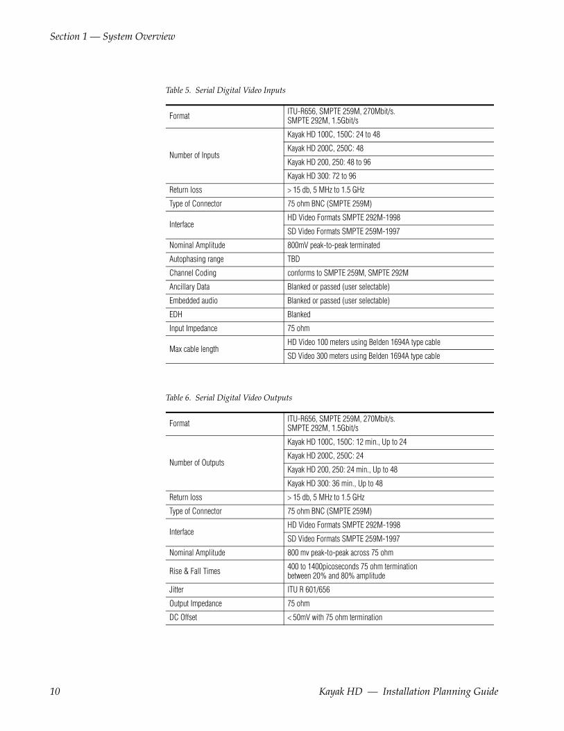
Table 5. Serial Digital Video Inputs
Table 6. Serial Digital Video Outputs
Format ITU-R656, SMPTE 259M, 270Mbit/s.SMPTE 292M, 1.5Gbit/s
Number of Inputs
Kayak HD 100C, 150C: 24 to 48
Kayak HD 200C, 250C: 48
Kayak HD 200, 250: 48 to 96
Kayak HD 300: 72 to 96
Return loss > 15 db, 5 MHz to 1.5 GHz
Type of Connector 75 ohm BNC (SMPTE 259M)
InterfaceHD Video Formats SMPTE 292M-1998
SD Video Formats SMPTE 259M-1997
Nominal Amplitude 800mV peak-to-peak terminated
Autophasing range TBD
Channel Coding conforms to SMPTE 259M, SMPTE 292M
Ancillary Data Blanked or passed (user selectable)
Embedded audio Blanked or passed (user selectable)
EDH Blanked
Input Impedance 75 ohm
Max cable lengthHD Video 100 meters using Belden 1694A type cable
SD Video 300 meters using Belden 1694A type cable
Format ITU-R656, SMPTE 259M, 270Mbit/s.SMPTE 292M, 1.5Gbit/s
Number of Outputs
Kayak HD 100C, 150C: 12 min., Up to 24
Kayak HD 200C, 250C: 24
Kayak HD 200, 250: 24 min., Up to 48
Kayak HD 300: 36 min., Up to 48
Return loss > 15 db, 5 MHz to 1.5 GHz
Type of Connector 75 ohm BNC (SMPTE 259M)
InterfaceHD Video Formats SMPTE 292M-1998
SD Video Formats SMPTE 259M-1997
Nominal Amplitude 800 mv peak-to-peak across 75 ohm
Rise & Fall Times 400 to 1400picoseconds 75 ohm termination between 20% and 80% amplitude
Jitter ITU R 601/656
Output Impedance 75 ohm
DC Offset < 50mV with 75 ohm termination
10 Kayak HD — Installation Planning Guide

Specifications
Table 8. Kayak HD Video Standards
Table 7. Analog Reference Input
Video Standard
For HD Video: Tri-level Sync, Analog equivalent to the standard being used
For SD Video: Color Black, Analog equivalent to the standard being used
Return loss > 40dB, up to 5 MHz
Connectors 2 each BNC loop through for both HD and SD inputs
Impedance 75 ohm external
HD Mode SD Mode
1080i 29.97/30 SMPTE 274M Table 1-4, 5 525i 59.94 SMPTE 259M
1080i 25 SMPTE 274M Table 1-6 625i 50 SMPTE 259M
1080p 24/23.976 SMPTE 274M Table 1-10, 11
1080sF 24/23.976 SMPTE 211 Table 1-15, 16
720p 60/59.94/50 SMPTE 296 Table 1-1, 2
Kayak HD — Installation Planning Guide 11
Section 1 — System Overview
12 Kayak HD — Installation Planning Guide
Section 2Control Surfaces
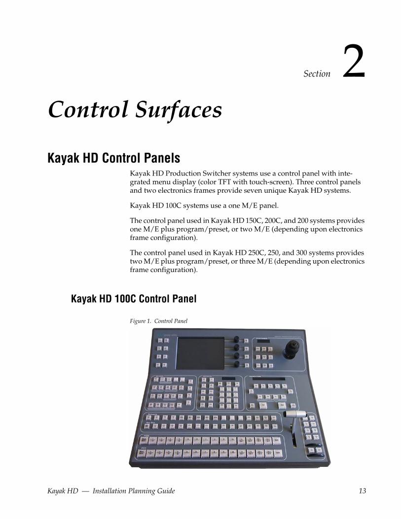
Kayak HD Control PanelsKayak HD Production Switcher systems use a control panel with inte-grated menu display (color TFT with touch-screen). Three control panels and two electronics frames provide seven unique Kayak HD systems.
Kayak HD 100C systems use a one M/E panel.
The control panel used in Kayak HD 150C, 200C, and 200 systems provides one M/E plus program/preset, or two M/E (depending upon electronics frame configuration).
The control panel used in Kayak HD 250C, 250, and 300 systems provides two M/E plus program/preset, or three M/E (depending upon electronics frame configuration).
Kayak HD 100C Control Panel
Figure 1. Control Panel
Kayak HD — Installation Planning Guide 13
Section 2 — Control Surfaces
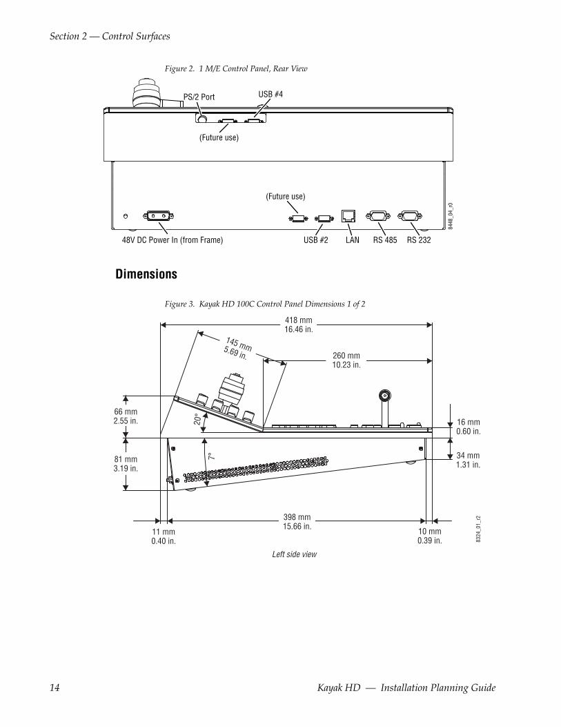
Figure 2. 1 M/E Control Panel, Rear View
Dimensions
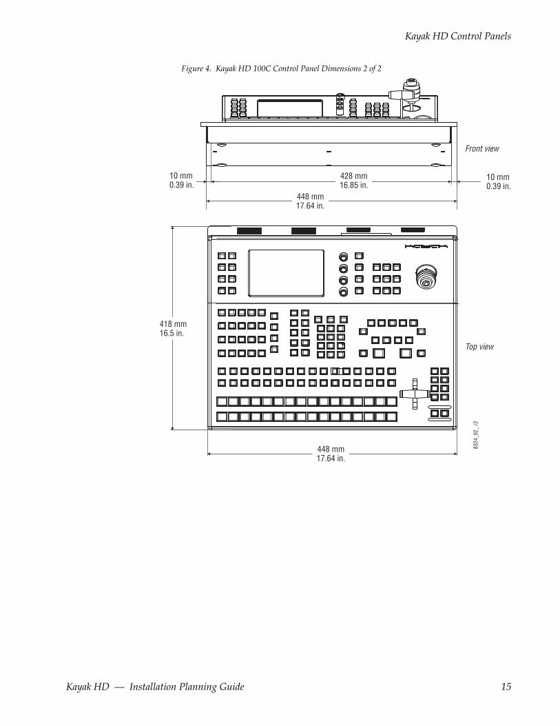
Figure 3. Kayak HD 100C Control Panel Dimensions 1 of 2
PS/2 Port
48V DC Power In (from Frame) LAN RS 485 RS 232
8448
_04_
r0
USB #4
USB #2
(Future use)
(Future use)
8324
_01_
r2
418 mm16.46 in.
398 mm15.66 in. 10 mm
0.39 in.
34 mm1.31 in.
16 mm0.60 in.
11 mm0.40 in.
66 mm2.55 in.
81 mm3.19 in.
260 mm10.23 in.
145 mm5.69 in.
Left side view
20°
7°
14 Kayak HD — Installation Planning Guide
Kayak HD Control Panels
Figure 4. Kayak HD 100C Control Panel Dimensions 2 of 2
448 mm17.64 in.
448 mm17.64 in.
428 mm16.85 in.
10 mm0.39 in.
418 mm16.5 in.
10 mm0.39 in.
Front view
Top view
8324
_02_
r2
Kayak HD — Installation Planning Guide 15
Section 2 — Control Surfaces
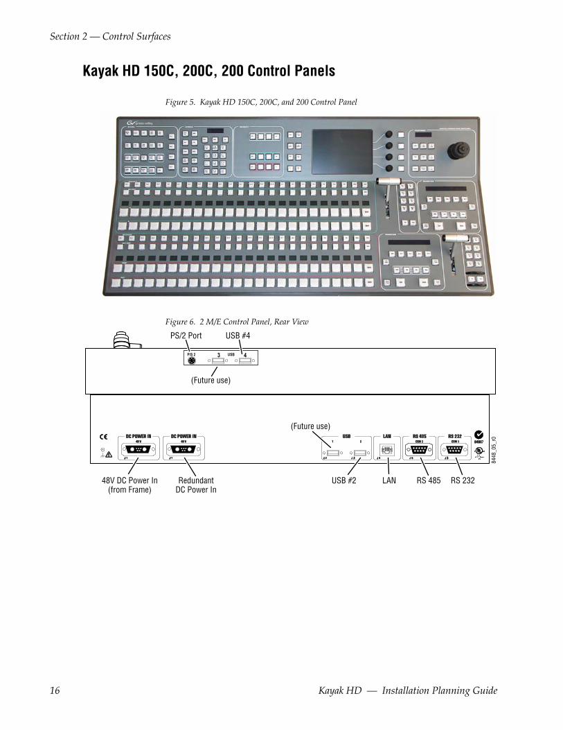
Kayak HD 150C, 200C, 200 Control Panels
Figure 5. Kayak HD 150C, 200C, and 200 Control Panel
Figure 6. 2 M/E Control Panel, Rear View
USBP/S 2 3 4
8448
_05_
r0
(Future use)
(Future use)
PS/2 Port
48V DC Power In(from Frame)
RedundantDC Power In
USB #4
LAN RS 485 RS 232USB #2
16 Kayak HD — Installation Planning Guide
Kayak HD Control Panels
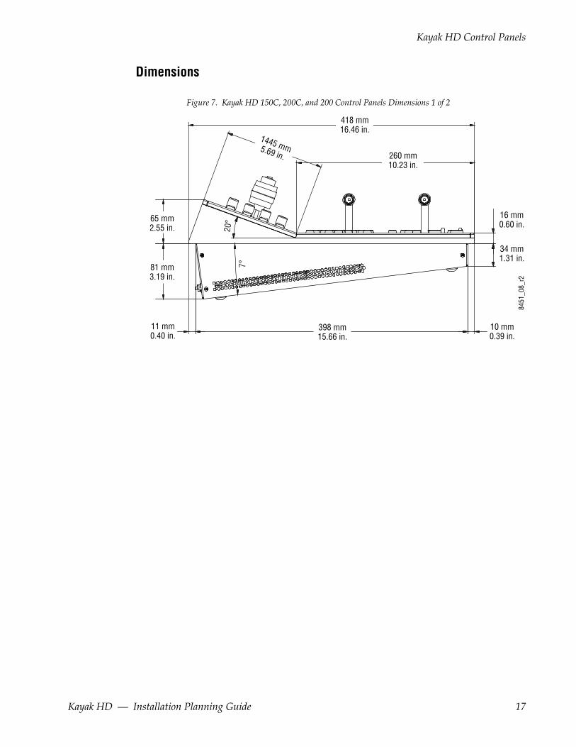
Dimensions
Figure 7. Kayak HD 150C, 200C, and 200 Control Panels Dimensions 1 of 2
418 mm16.46 in.
398 mm15.66 in.
10 mm0.39 in.
34 mm1.31 in.
16 mm0.60 in.
11 mm0.40 in.
65 mm2.55 in.
81 mm3.19 in.
260 mm10.23 in.
1445 mm5.69 in.
8451
_08_
r2
20°
7°
Kayak HD — Installation Planning Guide 17

Section 2 — Control Surfaces
Figure 8. Kayak HD 150C, 200C, and 200 Control Panel Dimensions 2 of 2
809 mm31.9 in.
809 mm31.9 in.
789 mm31.1 in.
418 mm16.5 in.
10 mm0.39 in.
10 mm0.39 in.
Front view
Top view
8451
_09_
r0
18 Kayak HD — Installation Planning Guide
Kayak HD Control Panels
Kayak HD 250C, 250, 300 Control Panels
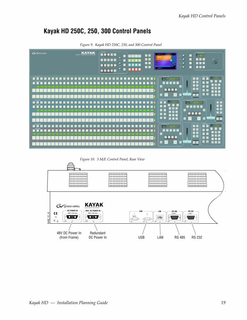
Figure 9. Kayak HD 250C, 250, and 300 Control Panel
Figure 10. 3 M/E Control Panel, Rear View
J1A J1B
DIGITAL PRODUCTION SWITCHER
J2 J3 J4 J5 J5
DC POWER IN48V/1.3A max. 48V/1.3A max.
RED. DC POWER IN USB LAN RS 485 RS 2321 2 COM 2 COM 1
Spare
TE
KAYAK
48V DC Power In(from Frame)
RedundantDC Power In LANUSB RS 485 RS 232
8448
_12_
r0
Kayak HD — Installation Planning Guide 19

Section 2 — Control Surfaces
Dimensions
Figure 11. Kayak HD 250C, 250, and 300 Control Panels Dimensions
10 mm0.39 in.
97 mm3.79 in.
524 mm20.63 in. 10 mm
0.39 in.
34 mm1.31 in.
8451
_01_
r0
65 mm2.54 in.
Left side view
20°
7°
44.57 in.1132 mm
43.78 in.1112 mm
0.39 in.10 mm
0.39 in.10 mm
21.42 in.544 mm
8451
_10_
r0
Front view
Top view
20 Kayak HD — Installation Planning Guide
Kayak HD Control Panels
Panel Mounting OptionsKayak HD control panels may be placed on a table or similar stable surface, or they may be recessed into a control console in an appropriately sized cutout.
Table Top UseHigh-friction feet prevent inadvertent movement of the panel. The panel is ventilated at its sides. Ensure that production materials and other equip-ment does not block the ventilation holes on the sides of the panel.
CAUTION At least 2 in. (50mm) of open space on the sides of the panel is required for proper air flow.
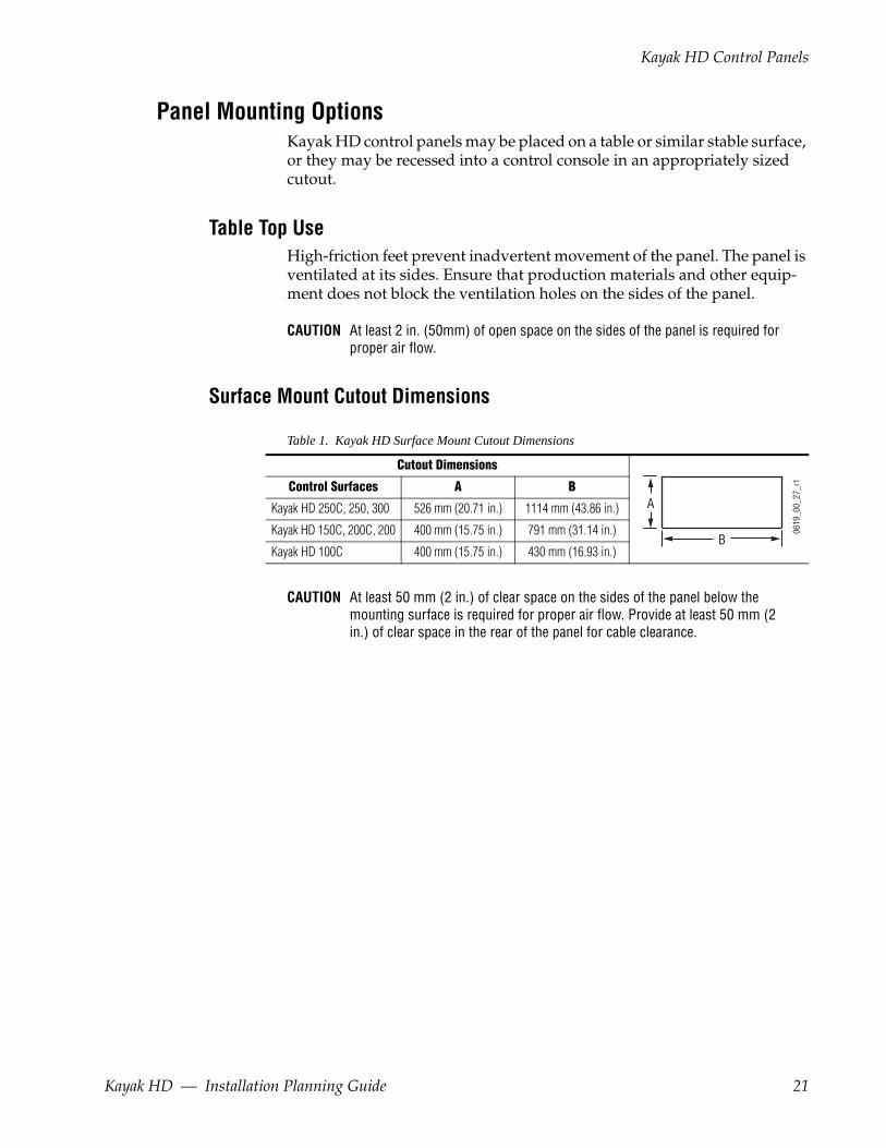
Surface Mount Cutout Dimensions
CAUTION At least 50 mm (2 in.) of clear space on the sides of the panel below the mounting surface is required for proper air flow. Provide at least 50 mm (2 in.) of clear space in the rear of the panel for cable clearance.
Table 1. Kayak HD Surface Mount Cutout Dimensions
Cutout Dimensions
Control Surfaces A B
Kayak HD 250C, 250, 300 526 mm (20.71 in.) 1114 mm (43.86 in.)
Kayak HD 150C, 200C, 200 400 mm (15.75 in.) 791 mm (31.14 in.)
Kayak HD 100C 400 mm (15.75 in.) 430 mm (16.93 in.)B
A
0619
_00_
27_r
1
Kayak HD — Installation Planning Guide 21
Section 2 — Control Surfaces
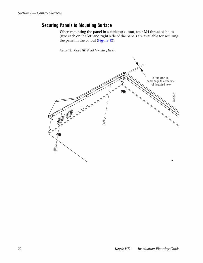
Securing Panels to Mounting SurfaceWhen mounting the panel in a tabletop cutout, four M4 threaded holes (two each on the left and right side of the panel) are available for securing the panel in the cutout (Figure 12).
Figure 12. Kayak HD Panel Mounting Holes
5 mm (0.2 in.)panel edge to centerline
of threaded hole
8324
_10_
r3
22 Kayak HD — Installation Planning Guide
Section 3Frames
General Rack Mounting InstructionsThe maximum ambient temperature for this unit is 40-degrees C (104-degrees F).
Installing the frame in a closed or multi-unit rack assembly together with other units could increase the maximum ambient temperature for this unit.
If the unit is installed in a rack, no ventilation openings should be blocked or otherwise covered. Make sure you install the frame so that you allow for cooling airflow.
Make sure that you mount the unit in the rack so that it is evenly balanced to prevent damage to the frame and to avoid creating a hazardous condi-tion.
When connecting the unit to the supply circuit be sure that the supply circuit of the rack is not overloaded. The unit must be well-grounded using the ground connector on the rear. When connecting the unit in a closed or multi-unit rack assembly together with other units be sure that the sum of the touch (leakage) currents for all power supplies does not exceed 3.5 mA.
CAUTION Ambient air temperature must be taken into consideration when installing your Kayak video processor chassis. Do not place the air intake side of the Kayak chassis near the air output of another piece of equipment if that output exceeds the maximum Operating Temperature specification.
Kayak HD — Installation Planning Guide 23
Section 3 — Frames
4 RU Compact Frame
Video Processor Frame Installation
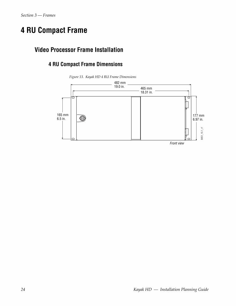
4 RU Compact Frame Dimensions
Figure 13. Kayak HD 4 RU Frame Dimensions
177 mm6.97 in.
482 mm19.0 in. 465 mm
18.31 in.
165 mm6.5 in.
Front view
8451
_15.
1_r1
24 Kayak HD — Installation Planning Guide
4 RU Compact Frame
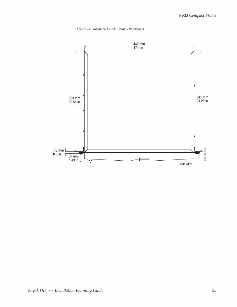
Figure 14. Kayak HD 4 RU Frame Dimensions
442 mm17.4 in.
541 mm21.29 in.
37 mm1.43 in.
523 mm20.58 in.
7.5 mm0.3 in.
Top view
8451
_15.
2_r0
Kayak HD — Installation Planning Guide 25
Section 3 — Frames
4 RU Compact Frame Rack Mounting
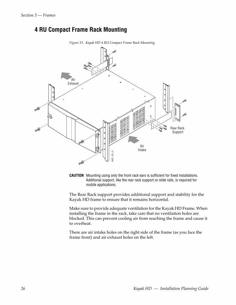
Figure 15. Kayak HD 4 RU Compact Frame Rack Mounting
CAUTION Mounting using only the front rack ears is sufficient for fixed installations. Additional support, like the rear rack support or slide rails, is required for mobile applications.
The Rear Rack support provides additional support and stability for the Kayak HD frame to ensure that it remains horizontal.
Make sure to provide adequate ventilation for the Kayak HD Frame. When installing the frame in the rack, take care that no ventilation holes are blocked. This can prevent cooling air from reaching the frame and cause it to overheat.
There are air intake holes on the right side of the frame (as you face the frame front) and air exhaust holes on the left.
AirIntake
Rear Rack Support
AirExhaust
8451
_05_
r3
26 Kayak HD — Installation Planning Guide
4 RU Compact Frame
CAUTION A minimum vertical clearance of 7.62 mm (0.3-in.) above the Kayak HD 4 RU Compact frame door is required to remove the door. When installing the Kayak HD 4 RU Compact frame in the rack, take care to leave room for removal of the front door. The front door lifts off vertically and must have suf-ficient clearance room in order to remove it. If you have equipment mounted too close to the Kayak HD 4 RU Compact Frame, you may not be able to remove the door.
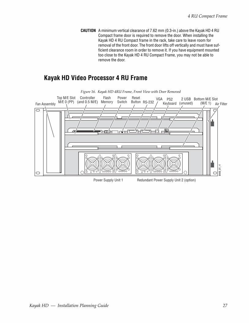
Kayak HD Video Processor 4 RU Frame
Figure 16. Kayak HD 4RU Frame, Front View with Door Removed
ONOFF
Top M/E SlotM/E 0 (PP)
Bottom M/E Slot(M/E 1)
Controller(and 0.5 M/E)
2 USB(unused) Air FilterFan Assembly
FlashMemory
PowerSwitch
ResetButton RS-232
Power Supply Unit 1 Redundant Power Supply Unit 2 (option)
8448
_01_
r1
PS2Keyboard
VGA
Kayak HD — Installation Planning Guide 27
Section 3 — Frames
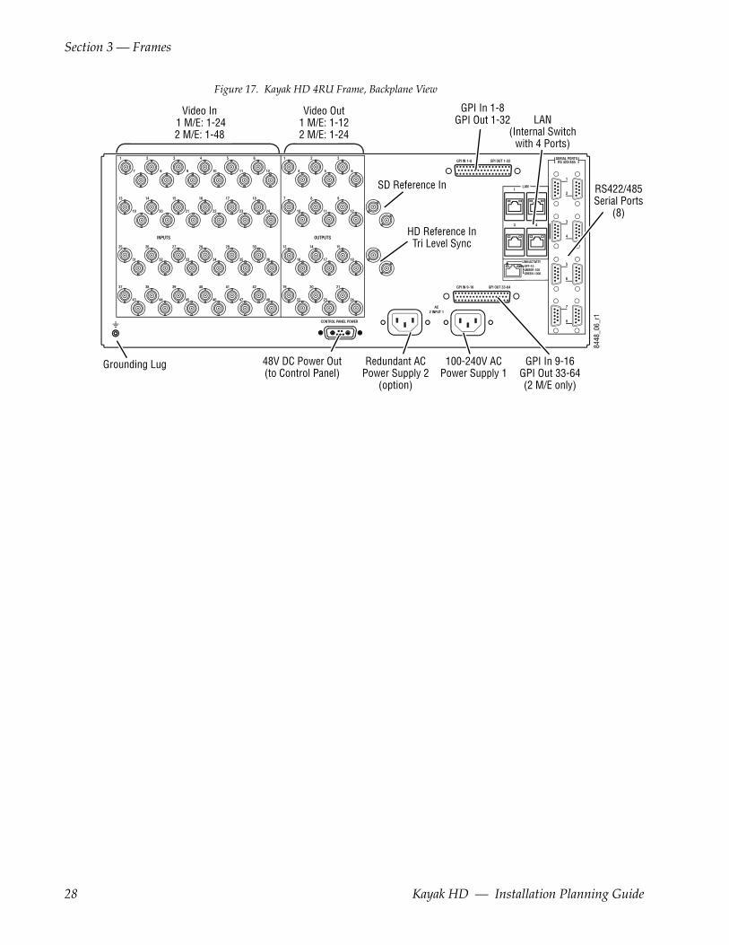
Figure 17. Kayak HD 4RU Frame, Backplane View
OFF-10AMBER-100GREEN-1000
LINK/ACTIVITY
8448
_06_
r1
48V DC Power Out(to Control Panel)
100-240V ACPower Supply 1
Redundant ACPower Supply 2
(option)
Grounding Lug GPI In 9-16GPI Out 33-64(2 M/E only)
GPI In 1-8GPI Out 1-32
HD Reference InTri Level Sync
Video Out1 M/E: 1-122 M/E: 1-24
Video In 1 M/E: 1-242 M/E: 1-48
SD Reference In
LAN(Internal Switch
with 4 Ports)
RS422/485Serial Ports
(8)
28 Kayak HD — Installation Planning Guide
8 RU Frame
8 RU Frame
Video Processor Frame Installation
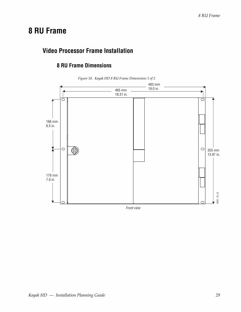
8 RU Frame Dimensions
Figure 18. Kayak HD 8 RU Frame Dimensions 1 of 2
483 mm19.0 in.465 mm
18.31 in.
166 mm6.5 in.
178 mm7.0 in.
355 mm13.97 in.
8451
_16_
r0
Front view
Kayak HD — Installation Planning Guide 29
Section 3 — Frames
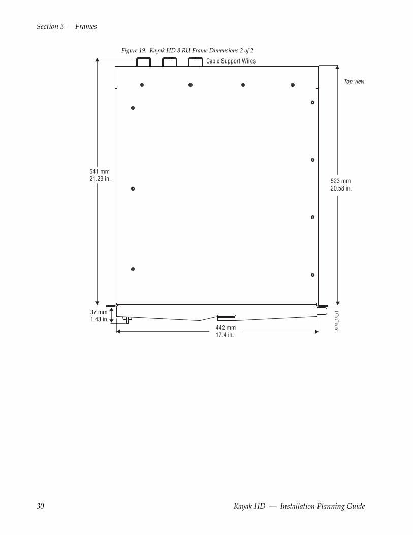
Figure 19. Kayak HD 8 RU Frame Dimensions 2 of 2
523 mm20.58 in.
541 mm21.29 in.
Cable Support Wires
442 mm17.4 in.
8451
_13_
r1
Top view
37 mm1.43 in.
30 Kayak HD — Installation Planning Guide

8 RU Frame
8 RU Frame Rack Mounting
Figure 20. Kayak HD 8 RU Frame Dimensions
CAUTION Mounting using only the front rack ears is sufficient for fixed installations. Additional support, like the rear rack support or slide rails, is required for mobile applications.
The Rear Rack support provides additional support and stability for the Kayak HD frame to ensure that it remains horizontal.
AirIntake
Rear Rack Support
AirExhaust
8451
_14_
r1
Kayak HD — Installation Planning Guide 31

Section 3 — Frames
Make sure to provide adequate ventilation for the Kayak HD Frame. When installing the frame in the rack, take care that no ventilation holes are blocked. This can prevent cooling air from reaching the frame and cause it to overheat.
There are air intake holes on the right side of the frame (as you face the frame front) and air exhaust holes on the left.
CAUTION A minimum vertical clearance of 7.62 mm (0.3-in.) above the Kayak HD 8 RU frame door is required to remove the door. When installing the Kayak HD 8 RU frame in the rack, take care to leave room for removal of the front door. The front door lifts off vertically and must have sufficient clearance room in order to remove it. If you have equipment mounted too close to the Kayak HD 8 RU Frame, you may not be able to remove the door.
Figure 21. Kayak HD 8RU Frame, Front View with Door RemovedONOF
F
M/E 0(PP)
M/E 1
M/E 2
M/E 3
ExpansionSlot
Controller(and 0.5 M/E)
Fan Assembly FlashMemory
PowerSwitch
ResetButton
2 USB(unused)
Air Filter
Power Supply Unit 1 Power Supply Unit 2 Power Supply Unit 3 (Optional)
RS-232 PS2KeyboardVGA
8448
11r1
32 Kayak HD — Installation Planning Guide

8 RU Frame
Figure 22. Kayak HD 8RU Frame, Backplane View
8448
_64_
r0
48V DC Power Out(to Control Panel)
100-240V ACPower Supply 1
Redundant ACPower Supply 3
(option)
100-240V ACPower Supply 2
Grounding Lug
GPI In 9-16GPI Out 33-64(2 M/E only)
GPI In 1-8GPI Out 1-32
HD Reference InTri Level Sync
Video Out1 M/E: 1-122 M/E: 1-243 M/E: 1-48
Video In1 M/E: 1-242 M/E: 1-483 M/E: 1-96
SD Reference In
LAN(Internal Switch
with 4 Ports)
RS422/485Serial Ports
(8)
Kayak HD — Installation Planning Guide 33
Section 3 — Frames
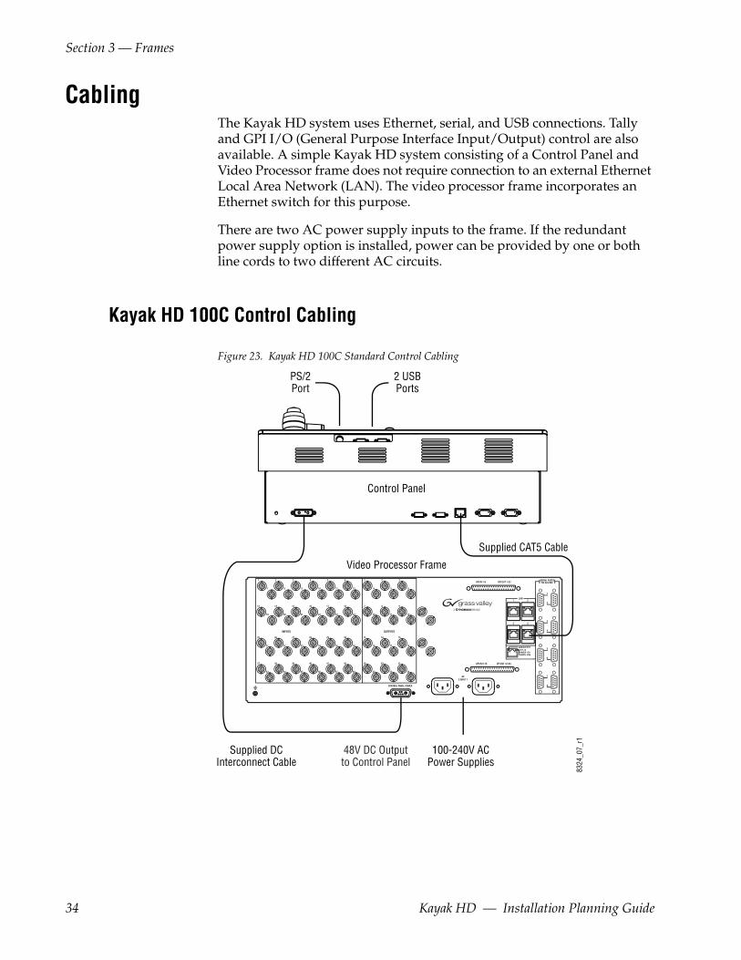
CablingThe Kayak HD system uses Ethernet, serial, and USB connections. Tally and GPI I/O (General Purpose Interface Input/Output) control are also available. A simple Kayak HD system consisting of a Control Panel and Video Processor frame does not require connection to an external Ethernet Local Area Network (LAN). The video processor frame incorporates an Ethernet switch for this purpose.
There are two AC power supply inputs to the frame. If the redundant power supply option is installed, power can be provided by one or both line cords to two different AC circuits.
Kayak HD 100C Control Cabling
Figure 23. Kayak HD 100C Standard Control Cabling
2 USBPorts
Supplied CAT5 Cable
PS/2Port
Control Panel
Video Processor Frame
100-240V ACPower Supplies
48V DC Outputto Control Panel
8324
_07_
r1
OFF-10AMBER-100GREEN-1000
LINK/ACTIVITY
Supplied DCInterconnect Cable
34 Kayak HD — Installation Planning Guide
Cabling
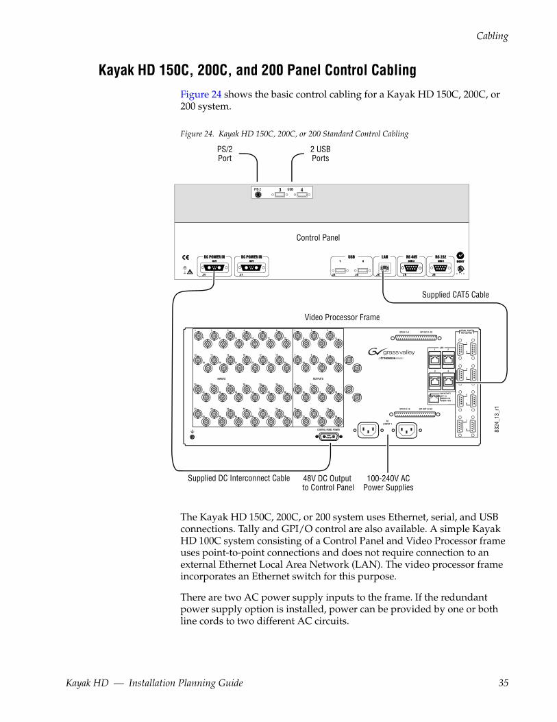
Kayak HD 150C, 200C, and 200 Panel Control CablingFigure 24 shows the basic control cabling for a Kayak HD 150C, 200C, or 200 system.
Figure 24. Kayak HD 150C, 200C, or 200 Standard Control Cabling
The Kayak HD 150C, 200C, or 200 system uses Ethernet, serial, and USB connections. Tally and GPI/O control are also available. A simple Kayak HD 100C system consisting of a Control Panel and Video Processor frame uses point-to-point connections and does not require connection to an external Ethernet Local Area Network (LAN). The video processor frame incorporates an Ethernet switch for this purpose.
There are two AC power supply inputs to the frame. If the redundant power supply option is installed, power can be provided by one or both line cords to two different AC circuits.
USBP/S 2 3 4
OFF-10AMBER-100GREEN-1000
LINK/ACTIVITY
Supplied CAT5 Cable
Supplied DC Interconnect Cable
8324
_13_
r1
Control Panel
Video Processor Frame
48V DC Output to Control Panel
100-240V ACPower Supplies
2 USBPorts
PS/2Port
Kayak HD — Installation Planning Guide 35
Section 3 — Frames
Network Cabling
Ethernet Switches and HubsA Kayak HD system requires a LAN when components other than a Control Panel and Video Processor frame are connected, or when external network access to a file system is desired. An appropriately-sized Ethernet switch may be required. An existing facility Ethernet switch (not hub) can support Kayak HD if an adequate number of ports are available.
A hub can be used only if there is a need to exceed 328 ft. (100 m) between a Control Panel and Video Processor frame. If a hub is used, connect the hub to the switch via the Uplink port, or through a peer-to-peer crossover cable.
Table 9 details Ethernet specifications. All Ethernet components are to be supplied by the customer except the CAT5 crossover cable provided
Note The supplied crossover cable works with the Kayak HD switcher because the frame has an auto-sensing Ethernet switch.
CAUTION An existing facility Ethernet switch (not hub) can support Kayak HD if an ade-quate number of ports are available. Keep your facility network and technical network separate in order to avoid network traffic negatively affecting Kayak HD system operation.
The Kayak HD backplane has four RJ45 Ethernet connectors for its built-in Ethernet switch, each capable of 10/100/1000 Mbps. All Ethernet connec-tors share the same speed- and direction-sensing features.
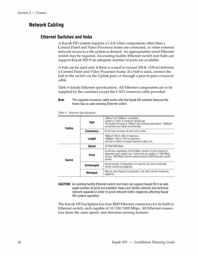
Table 9. Ethernet Specifications
Cables
Type10BaseT and 100BaseT compatible. Category 5 cable, 8 conductor twisted pair.The system will work at 10BaseT with reduced performance. 100BaseT components are highly recommended.
Connectors RJ-45 male connector at each end of cable.
Length10BaseT: 984 ft. (300 m) maximum. 100BaseT: 328 ft. (100 m) maximum.Use hub or switch to exceed maximum cable runs.
Switch
Speed 10/100/1000 Mbps
PortsRJ-45 auto-negotiating 10/100 Mbps; number of ports required is dependent upon system size. Frame ports are capable of 1000 Mbps. Using a 1000 Mbps Ethernet switch enhances RAM Recorder transfer speeds.
Unmanaged Recommended. Configuration not required, but does not provide remote monitoring capability.
Managed May be used. Requires configuration, but offers remote monitoring capability.
36 Kayak HD — Installation Planning Guide

Cabling
One Ethernet connector must connect to the Control Panel. It may go through a switch to make the Control Panel connection, but at least one connector must be connected from the Frame to the Control Panel somehow.
One Ethernet connector may be connected to the Facility LAN if desired. The other two Ethernet connectors may be connected to other devices if needed.
Note If you do connect these extra Ethernet connectors to other devices, please note that these other devices will not communicate if the switcher frame is turned off for any reason. For that reason, it is preferable to connect Ethernet ports coming from the switcher only to other devices that are switcher-related.
Factory Network SettingsThe default factory setting for the IP address is
• 192.168.0.70 for the video processor frame
• 192.168.0.73 for the control panel
The Device Setup menu allows to change the IP address. It is only allowed to change the last octet of the IP address (to accommodate Kayak HDs on the same network).
Note In order to integrate Kayak HD devices into an existing network, ask the local network administrator for the subnet mask of the network. Before changing IP addresses always set the subnet masks of the Kayak HD devices to the mask of the local network. If all changes are made and a frame is not visible to the panel, press 'Rescan' in the “Device Control” menu of the panel.
Video Cabling for all Kayak HD SwitchersAll Kayak HD system video inputs and outputs are configurable. For cabling configuration flexibility, each external primary input can be mapped to any Kayak HD panel source select button, as can each internal video system source. Any Kayak HD system video signal, such as M/E program, preview, clean feed, or PGM/PST, can be mapped to any output bus to be accessed on a specific connector, or an output bus can act as an auxiliary bus.
InputsNon-looping video inputs on the back of the Video Processor frame are numbered 1 through 24 and 25 through 48 on the 4 RU frame. Each accepts a 270 MHz serial digital video signal, or 1.485 Gb. The number of inputs that are active depends on the number of full mix/effects or I/O Expansion modules that are installed in the chassis. There are 24 inputs active for every mix/effects module and expansion module installed.
Kayak HD — Installation Planning Guide 37
Section 3 — Frames
OutputsThe outputs on the back of the Video Processor frame are numbered 1 through 12 and 13 through 24 on the 4RU frame. All of the outputs carry the same video format, as determined by standard selected and by the ref-erence signals connected. The number of outputs that are active depends on the number of full mix/effects or I/O Expansion modules installed in the chassis. There are 12 outputs active for every mix/effects and expansion module installed.
Reference InputThere are two separate, looping reference input pairs. The upper pair accepts analog 525 or 625 composite video. Burst is not required, but typi-cally facility reference color black is used. Kayak HD can auto-sense whether the reference is 525 or 625 and can change the internal standard accordingly.
The lower looping reference input pair is for HD production and uses analog tri-level sync.
75-ohm termination of one of each of these looping inputs is required, either directly on the adjacent connector or at the end of a daisy chain looping to other equipment.
Any one of the SDI inputs can also be used as reference in the respective standard.
38 Kayak HD — Installation Planning Guide

Section 4Options
KHD-PSU Internal Redundant Power Supply OptionThis option provides redundant power for the Kayak HD video processor chassis and control panel. It slides into an extra power supply slot in the video processor chassis.
Figure 25. KHD-PSU Internal Redundant Power Supply Option
Kayak HD — Installation Planning Guide 39

Section 4 — Options
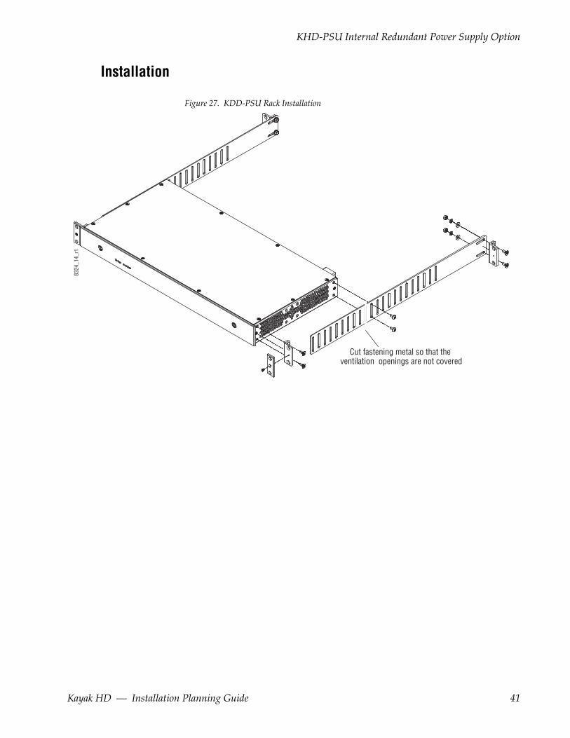
KDD-PSU Power Supply OptionThe KDD-PSU option is a 1RU frame unit designed for rack mounting as shown in Figure 27 on page 41. It features a wide range AC power supply providing power for a remotely-mounted Kayak HD Control Panel or for each additional Control Panel connected to the same processor chassis.
Power output is sufficient for two 1 M/E systems or one 2 M/E system.
Grass Valley recommends that customers purchase this option if the dis-tance from the Frame to the Control Panel is more than 100 meters.
Figure 26. KDD-PSU
KDD
-PSU
-Fro
nt-L
eft
40 Kayak HD — Installation Planning Guide
KHD-PSU Internal Redundant Power Supply Option
Installation
Figure 27. KDD-PSU Rack Installation
Cut fastening metal so that the ventilation openings are not covered
8324
_14_
r1
Kayak HD — Installation Planning Guide 41
Section 4 — Options
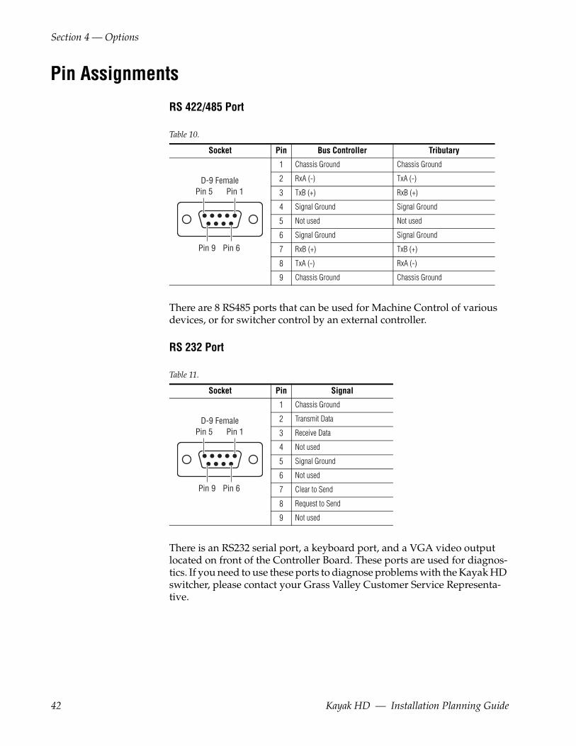
Pin Assignments
RS 422/485 Port
There are 8 RS485 ports that can be used for Machine Control of various devices, or for switcher control by an external controller.
RS 232 Port
There is an RS232 serial port, a keyboard port, and a VGA video output located on front of the Controller Board. These ports are used for diagnos-tics. If you need to use these ports to diagnose problems with the Kayak HD switcher, please contact your Grass Valley Customer Service Representa-tive.
Table 10.
Socket Pin Bus Controller Tributary
1 Chassis Ground Chassis Ground
2 RxA (-) TxA (-)
3 TxB (+) RxB (+)
4 Signal Ground Signal Ground
5 Not used Not used
6 Signal Ground Signal Ground
7 RxB (+) TxB (+)
8 TxA (-) RxA (-)
9 Chassis Ground Chassis Ground
Table 11.
Socket Pin Signal
1 Chassis Ground
2 Transmit Data
3 Receive Data
4 Not used
5 Signal Ground
6 Not used
7 Clear to Send
8 Request to Send
9 Not used
Pin 1Pin 5
Pin 6Pin 9
D-9 Female
Pin 1Pin 5
Pin 6Pin 9
D-9 Female
42 Kayak HD — Installation Planning Guide
GPI / Tally Connections
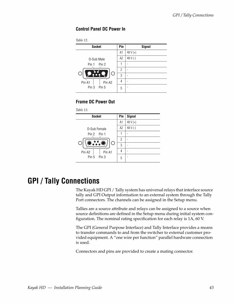
Control Panel DC Power In
Frame DC Power Out
GPI / Tally ConnectionsThe Kayak HD GPI / Tally system has universal relays that interface source tally and GPI Output information to an external system through the Tally Port connectors. The channels can be assigned in the Setup menu.
Tallies are a source attribute and relays can be assigned to a source when source definitions are defined in the Setup menu during initial system con-figuration. The nominal rating specification for each relay is 1A, 60 V.
The GPI (General Purpose Interface) and Tally Interface provides a means to transfer commands to and from the switcher to external customer pro-vided equipment. A “one wire per function” parallel hardware connection is used.
Connectors and pins are provided to create a mating connector.
Table 12.
Socket Pin Signal
A1 48 V (+)
A2 48 V (-)
1 -
2 -
3 -
4 -
5 -
Table 13.
Socket Pin Signal
A1 48 V (+)
A2 48 V (-)
1 -
2 -
3 -
4 -
5 -
Pin A2
Pin 2Pin 1
Pin A1Pin 5Pin 3
D-Sub Male
Pin A1
Pin 1Pin 2
Pin A2Pin 3Pin 5
D-Sub Female
Kayak HD — Installation Planning Guide 43
Section 4 — Options
Kayak HD GPI and Tally InterfaceThe Kayak HD is highly modular and configurable. This document describes various possibilities for tally interconnections.
There are two 50 pin female subminiature 'D' connectors on the rear of the 4 RU Kayak HD frame and four connectors on the rear of the 8 RU Kayak HD frame. Each connector is activated by the presence of a Mix/Effects module installed in the frame. A one M/E switcher (4 RU or 8 RU frame) activates only the first connector. Two M/Es activate two connectors, and so forth, up to four connectors activated by a four M/E system.
GPI inputs and outputs are assigned as follows:
• GPI in 1 - 8 and GPI/Tally out 1 - 32 routed to the first connector.
• GPI in 9 - 16 and GPI/Tally out 33 - 64 routed to the second connector.
• GPI in 17 - 24 and GPI/Tally out 65 - 96 routed to the third connector (8 RU frame only).
• GPI in 25 - 32 and GPI/Tally out 97 - 128 routed to the fourth connector (8 RU frame only).
For pinouts of these connectors refer to the listings in:
• 4 RU and 8RU Frame Tally (GPI In 1-8, GPI Out 1-32) on page 49
• 4 RU and 8RU Frame Tally (GPI In 9-16, GPI Out 33-64) on page 50
• 8RU Frame Tally (GPI In 17-24, GPI Out 65-96) on page 51
• 8RU Frame Tally (GPI In 25-32, GPI Out 97-128) on page 52
These four connectors do not share any signals in common other than ground reference and chassis ground. Because of this, some GPI / Tally interconnects may require external common connections between connec-tors, as explained below.
GPI InputsThe purpose of the GPI In pins is to provide a stimulus from the customer's equipment to the switcher.
A simple connection to the two connectors (or four in the case of the 8 RU frame) activates the corresponding input. This kind of control is suitable for a connection to a relay contact or to an open-collector output.
WARNING When connecting to an open-collector output, there is no ground potential isolation between the Video Processor frame and controlling devices.
Since the circuit ground is led out of the device, the cabling has to be shielded for this kind of control. Non-shielded cables may cause EMC and/or ESD problems.
44 Kayak HD — Installation Planning Guide
GPI / Tally Connections
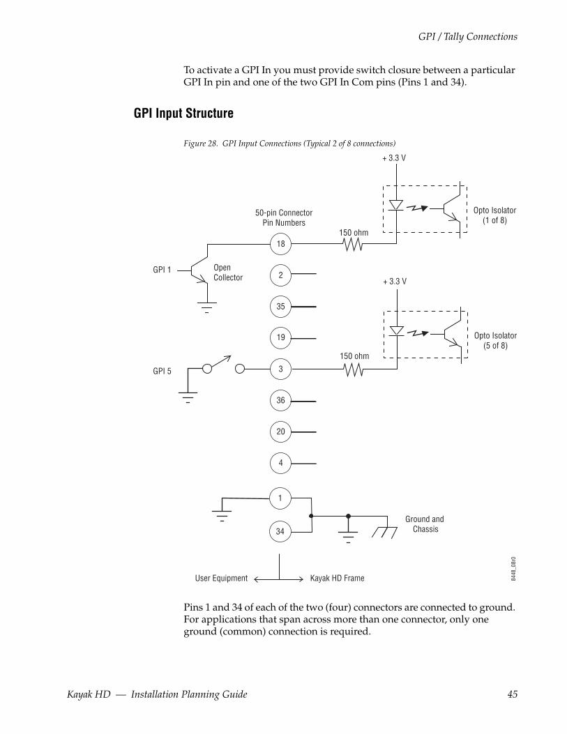
To activate a GPI In you must provide switch closure between a particular GPI In pin and one of the two GPI In Com pins (Pins 1 and 34).
GPI Input Structure
Figure 28. GPI Input Connections (Typical 2 of 8 connections)
Pins 1 and 34 of each of the two (four) connectors are connected to ground. For applications that span across more than one connector, only one ground (common) connection is required.
50-pin ConnectorPin Numbers
Opto Isolator(1 of 8)
GPI 1
GPI 5
+ 3.3 V
OpenCollector
18
35
19
36
20
4
1
34
3
2
150 ohm
Opto Isolator(5 of 8)
Ground and Chassis
Kayak HD FrameUser Equipment
+ 3.3 V
150 ohm
8448
_08r
0
Kayak HD — Installation Planning Guide 45
Section 4 — Options
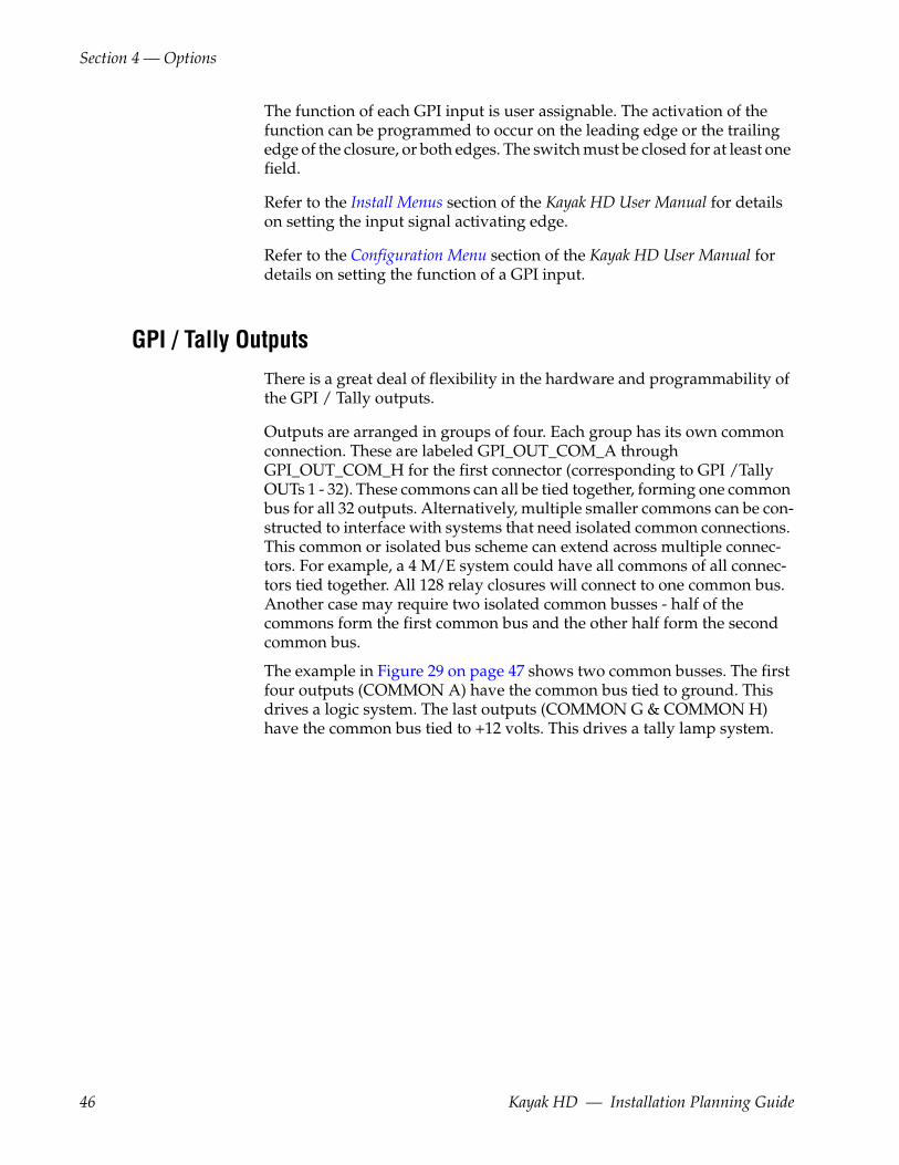
The function of each GPI input is user assignable. The activation of the function can be programmed to occur on the leading edge or the trailing edge of the closure, or both edges. The switch must be closed for at least one field.
Refer to the Install Menus section of the Kayak HD User Manual for details on setting the input signal activating edge.
Refer to the Configuration Menu section of the Kayak HD User Manual for details on setting the function of a GPI input.
GPI / Tally OutputsThere is a great deal of flexibility in the hardware and programmability of the GPI / Tally outputs.
Outputs are arranged in groups of four. Each group has its own common connection. These are labeled GPI_OUT_COM_A through GPI_OUT_COM_H for the first connector (corresponding to GPI /Tally OUTs 1 - 32). These commons can all be tied together, forming one common bus for all 32 outputs. Alternatively, multiple smaller commons can be con-structed to interface with systems that need isolated common connections. This common or isolated bus scheme can extend across multiple connec-tors. For example, a 4 M/E system could have all commons of all connec-tors tied together. All 128 relay closures will connect to one common bus. Another case may require two isolated common busses - half of the commons form the first common bus and the other half form the second common bus.
The example in Figure 29 on page 47 shows two common busses. The first four outputs (COMMON A) have the common bus tied to ground. This drives a logic system. The last outputs (COMMON G & COMMON H) have the common bus tied to +12 volts. This drives a tally lamp system.
46 Kayak HD — Installation Planning Guide

GPI / Tally Connections
Figure 29. GPO Tally Connections
50-pin ConnectorPin Numbers
1A of 32
2A of 32
3A of 32
4A of 32
5B of 32
6B of 32
27G of 32
28G of 32
29H of 32
30H of 32
31H of 32
32H of 32
Kayak HD Frame User Equipment
Common B
Common A
Common H
Logic
12V Lamp
12V Lamp
12V Lamp
+ 12V DC
Common G
8448
_09r
0
21
5
38
22
37
39
23
48
32
47
49
33
17
50
16
Kayak HD — Installation Planning Guide 47
Section 4 — Options
Although the diagram above implies mechanical relays, the actual outputs are implemented with solid state relays. Interface specifications are:
Maximum current for any one output: 1 amp AC/DC
Maximum current for any one common: 2 amp AC/DC.
Maximum off (open circuit) voltage between output and common: 60 Volts peak.
Maximum voltage between any point and ground (chassis): 60 Volts peak.
The solid state relays are bidirectional; either polarity voltage can be applied. If the switcher GPI / Tally outputs are used to drive downstream DC relays, be sure to install diodes across the relay coils to clamp inductive spikes. Shielded cable is recommended for the connection from the switcher to the user tally system.
Each output can be programmed for function, steady state or pulse, output polarity, and pulse duration.
Refer to the Install Menus section of the Kayak HD User Manual for details on setting the characteristics of the output signal (steady state, polarity, pulse duration, etc.).
Refer to the Configuration Menu section of the Kayak HD User Manual for details on setting the function of a GPO / Tally output (tally, auto trans, recall register, and so forth).
48 Kayak HD — Installation Planning Guide
GPI / Tally Connections
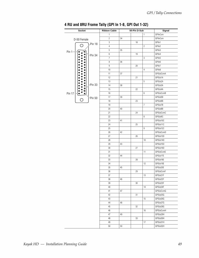
4 RU and 8RU Frame Tally (GPI In 1-8, GPI Out 1-32)Socket Ribbon Cable 50-Pin D-Sub Signal
1 1 GPIInCom
2 34 GPIInCom
3 18 GPIIn1
4 2 GPIIn2
5 35 GPIIn3
6 19 GPIIn4
7 3 GPIIn5
8 36 GPIIn6
9 20 GPIIn7
10 4 GPIIn8
11 37 GPIOutComA
12 21 GPIOut1A
13 5 GPIOut2A
14 38 GPIOut3A
15 22 GPIOut4A
16 6 GPIOutComB
17 39 GPIOut5B
18 23 GPIOut6B
19 7 GPIOut7B
20 40 GPIOut8B
21 24 GPIOutComC
22 8 GPIOut9C
23 41 GPIOut10C
24 25 GPIOut11C
25 9 GPIOut12C
26 42 GPIOutComD
27 26 GPIOut13D
28 10 GPIOut14D
29 43 GPIOut15D
30 27 GPIOut16D
31 11 GPIOutComE
32 44 GPIOut17E
33 28 GPIOut18E
34 12 GPIOut19E
35 45 GPIOut20E
36 29 GPIOutComF
37 13 GPIOut21F
38 46 GPIOut22F
39 30 GPIOut23F
40 14 GPIOut24F
41 47 GPIOutComG
42 31 GPIOut25G
43 15 GPIOut26G
44 48 GPIOut27G
45 32 GPIOut28G
46 16 GPIOutComH
47 49 GPIOut29H
48 33 GPIOut30H
49 17 GPIOut31H
50 50 GPIOut32H
D-50 Female
Pin 1
Pin 17
Pin 33
Pin 50
Pin 18
Pin 34
Kayak HD — Installation Planning Guide 49

Section 4 — Options
4 RU and 8RU Frame Tally (GPI In 9-16, GPI Out 33-64) Socket Ribbon Cable 50-Pin D-Sub Signal
1 1 GPIInCom
2 34 GPIInCom
3 18 GPIIn9
4 2 GPIIn10
5 35 GPIIn11
6 19 GPIIn12
7 3 GPIIn13
8 36 GPIIn14
9 20 GPIIn15
10 4 GPIIn16
11 37 GPIOutComJ
12 21 GPIOut33J
13 5 GPIOut34J
14 38 GPIOut35J
15 22 GPIOut36J
16 6 GPIOutComK
17 39 GPIOut37K
18 23 GPIOut38K
19 7 GPIOut39K
20 40 GPIOut40K
21 24 GPIOutComL
22 8 GPIOut41L
23 41 GPIOut42L
24 25 GPIOut43L
25 9 GPIOut44L
26 42 GPIOutComM
27 26 GPIOut45M
28 10 GPIOut46M
29 43 GPIOut47M
30 27 GPIOut48M
31 11 GPIOutComN
32 44 GPIOut49N
33 28 GPIOut50N
34 12 GPIOut51N
35 45 GPIOut52N
36 29 GPIOutComP
37 13 GPIOut53P
38 46 GPIOut54P
39 30 GPIOut55P
40 14 GPIOut56P
41 47 GPIOutComQ
42 31 GPIOut57Q
43 15 GPIOut58Q
44 48 GPIOut59Q
45 32 GPIOut60Q
46 16 GPIOutComR
47 49 GPIOut61R
48 33 GPIOut62R
49 17 GPIOut63R
50 50 GPIOut64R
D-50 Female
Pin 1
Pin 17
Pin 33
Pin 50
Pin 18
Pin 34
50 Kayak HD — Installation Planning Guide

GPI / Tally Connections
8RU Frame Tally (GPI In 17-24, GPI Out 65-96)Socket Ribbon Cable 50-Pin D-Sub Signal
1 1 GPIInCom
2 34 GPIInCom
3 18 GPIIn17
4 2 GPIIn18
5 35 GPIIn19
6 19 GPIIn20
7 3 GPIIn21
8 36 GPIIn22
9 20 GPIIn23
10 4 GPIIn24
11 37 GPIOutComS
12 21 GPIOut65S
13 5 GPIOut6S
14 38 GPIOut67S
15 22 GPIOut68S
16 6 GPIOutComT
17 39 GPIOut69T
18 23 GPIOut70T
19 7 GPIOut71T
20 40 GPIOut72T
21 24 GPIOutComU
22 8 GPIOut73U
23 41 GPIOut74U
24 25 GPIOut75U
25 9 GPIOut76U
26 42 GPIOutComV
27 26 GPIOut77V
28 10 GPIOut78V
29 43 GPIOut79V
30 27 GPIOut80V
31 11 GPIOutComW
32 44 GPIOut81W
33 28 GPIOut82W
34 12 GPIOut83W
35 45 GPIOut84W
36 29 GPIOutComX
37 13 GPIOut85X
38 46 GPIOut86X
39 30 GPIOut87X
40 14 GPIOut88X
41 47 GPIOutComY
42 31 GPIOut89Y
43 15 GPIOut90Y
44 48 GPIOut91Y
45 32 GPIOut92Y
46 16 GPIOutComZ
47 49 GPIOut93Z
48 33 GPIOut94Z
49 17 GPIOut95Z
50 50 GPIOut96Z
D-50 Female
Pin 1
Pin 17
Pin 33
Pin 50
Pin 18
Pin 34
Kayak HD — Installation Planning Guide 51

Section 4 — Options
8RU Frame Tally (GPI In 25-32, GPI Out 97-128) Socket Ribbon Cable 50-Pin D-Sub Signal
1 1 GPIInCom
2 34 GPIInCom
3 18 GPIIn25
4 2 GPIIn26
5 35 GPIIn27
6 19 GPIIn28
7 3 GPIIn29
8 36 GPIIn30
9 20 GPIIn31
10 4 GPIIn32
11 37 GPIOutComAA
12 21 GPIOut97AA
13 5 GPIOut98AA
14 38 GPIOut99AA
15 22 GPIOut100AA
16 6 GPIOutComAB
17 39 GPIOut101AB
18 23 GPIOut102AB
19 7 GPIOut103AB
20 40 GPIOut104AB
21 24 GPIOutComAC
22 8 GPIOut105AC
23 41 GPIOut106AC
24 25 GPIOut107AC
25 9 GPIOut108AC
26 42 GPIOutComAD
27 26 GPIOut109AD
28 10 GPIOut110AD
29 43 GPIOut111AD
30 27 GPIOut112AD
31 11 GPIOutComAE
32 44 GPIOut113AE
33 28 GPIOut114AE
34 12 GPIOut115AE
35 45 GPIOut116AE
36 29 GPIOutComAF
37 13 GPIOut117AF
38 46 GPIOut118AF
39 30 GPIOut119AF
40 14 GPIOut120AF
41 47 GPIOutComAG
42 31 GPIOut121AG
43 15 GPIOut122AG
44 48 GPIOut123AG
45 32 GPIOut124AG
46 16 GPIOutComAH
47 49 GPIOut125AH
48 33 GPIOut126AH
49 17 GPIOut127AH
50 50 GPIOut128AH
D-50 Female
Pin 1
Pin 17
Pin 33
Pin 50
Pin 18
Pin 34
52 Kayak HD — Installation Planning Guide
Index
Numerics100 C Control Panel 13
Dimensions 14150C, 200C, 200 Control Panels 16150C, 200C, and 200 Control Panels
Dimensions 17Panel Control Cabling 35
250C, 250, and 300 Control PanelsDimensions 20
4 RU Frame 24Dimensions 24Rack Mounting 26Video Processor 27
8 RU Frame 29Dimensions 29Rack Mounting 31Video Processor Installation 29
CCabling 34, 52
100C Control Cabling 34Control, 100c 34Control, 150C, 200C, and 200 35Network 36
Control Cabling100C 34150C, 200C, and 200 35
Control Panels100C, Dimensions 13150C, 200C, 200 16150C, 200C, and 200, Dimensions 17250C, 250, and 300
Dimensions 20Control Cabling 35
Control ProtocolsSupported 7
DDimensions
100C Control Panel 14
150C, 200C, and 200 Control Panels 17250C, 250, and 300 Control Panels 204 RU Compact Frame 248 RU Frame 29Surface Mount Cutout (All Panels) 21
documentation online 4
EEthernet Switches and Hubs 36
FFactory Network Settings 37FAQ database 4Frame
Video Processor Installation 24frequently asked questions 4
GGPI
Inputs 44Outputs 46
GPI Input Structure 45GPI Interface 44Grass Valley web site 4
HHubs
Ethernet 36
IInputs
GPI 44Reference 38Video Cabling 37
Installation8 RU Video Processor 29KDD-PSU Power Supply Option 41
Kayak HD — Installation Planning Guide 1
Index
Video Processor Frame 24
KKayak HD
100C Control Cabling 34100C Control Panel 13Backplane 36GPI and Tally Interface 44Introduction 3Network Cabling 36Switcher Models 3Systems 8Video Cabling 37
Kayak HD 250C, 250, 300 Control Panels 19Kayak HD Control Panels 13KDD-PSU
Power Supply Option 40Power Supply Option, Installation 41
KHD-PSUInternal Redundant Power Supply Option 39
NNetwork
Cabling 36Settings, Factory default 37
Oonline documentation 4Options 39
Kayak HD 6Outputs
GPI 46Video Cabling 38
PPanel Mounting Options 21Pin Assignments 42Power
KDD-PSU Power Supply Option 40KHD-PSU Internal Redundant Power Supply
Option 39Protocols
Supported Control Protocols 7
RRack Mounting
4 RU Compact Frame 268 RU Frame 31Instructions 23
ReferenceVideo Cabling Input 38
Ssoftware download from web 4Specifications 8Standard Features
Kayak HD 4Supported Control Protocols 7Surface Mount Cutout Dimensions 21Switcher Models
Kayak HD 3Switches
Ethernet 36
TTable Top Use 21Tally (GPI In 1-8, GPI Out 1-32) 49, 51Tally (GPI In 9-16, GPI Out 33-64) 50, 52Tally Interface 44
VVideo Cabling
Inputs 37Outputs 38Reference Input 38
Video Processor4 RU Frame 278 RU Frame Installation 29Frame Installation 24
Wweb site documentation 4web site FAQ database 4web site Grass Valley 4web site software download 4
2 Kayak HD — Installation Planning Guide

Index
ZZodiak 3
Kayak HD — Installation Planning Guide 3

Index
4 Kayak HD — Installation Planning Guide