Embed Size (px)
Citation preview
Bike Sport Developments Ltd Tel 0044 (0)1327 263942 – [email protected] / www.bikesportdevelopments.co.uk Manual revision 02, 18/04/2016
1 Bike Sport Developments Ltd Unit 3D Manor Business park, Grants Hill way, Woodford Halse, Northants, NN11 3UB - UK Tel: 0044 (0)1327 263942 Copyright – Bike Sport Developments Ltd - 2016
Kawasaki ZX10 – 2016 onwards Clutch-Free shifting……Perfected
Fitted in under an hour – Dealer installation only**
No ECU re-flash
Can be used in all power modes and adjusts the BLIP response automatically.
All existing bike systems, and sensors are retained
Integrates with the bike CAN bus.
No error codes on the dash when plugged in.
Uses the existing shifter sensor
Supplied with a BLIP-Map for your bike.
System may be re-programmed or adjusted by the additional USB interface and the WinBLIP software. Sold as a separate part.
Machined aluminium housing with fully sealed electronics and high specification ‘plug n play’ wiring.
Designed and made in the UK by Bike Sport Developments Ltd ** Home fitting not recommended as it is necessary to remove two tamper proof fasteners on the ECU to install this kit. This requires a specific service tool.
How it works – The Kawasaki ZX10-2016 uses a Ride By Wire system with sensors to read the twist grip % telling the ECU what the rider wants, and electric motors on the throttles carry this out. Between these 2 devices sits the ECU with maps and control strategies to make the bike safe and easier to ride in a wide range of conditions. Blip-Box reads signals from the twist grip sensors and data from the CAN bus and at the appropriate foot pressure from the rider it creates a BLIP on the throttle which releases the pressure on the gearbox allowing a perfect smooth back shift. Like a quick shifter, but in reverse.
Download the software, drivers and PDF manuals at
www.bikesportdevelopments.co.uk/blipbox

Bike Sport Developments Ltd Tel 0044 (0)1327 263942 – [email protected] / www.bikesportdevelopments.co.uk Manual revision 02, 18/04/2016
2 Bike Sport Developments Ltd Unit 3D Manor Business park, Grants Hill way, Woodford Halse, Northants, NN11 3UB - UK Tel: 0044 (0)1327 263942 Copyright – Bike Sport Developments Ltd - 2016
Important rider notes
Must be read and understood by all riders…
Blip will be activated under these conditions: o RPM is higher than 4200 o Rear wheel speed is higher than 30kmh o Throttle grip is closed (less than 3%, engine slowing down) o The time since the last blip must have been exceeded (0.35seconds) o There are no Blip Box diagnostics active (flashing LED) o QS (Quick shift) is active in the dash configuration. o Foot pressure is applied by the rider
The BLIP disengages the gearbox very much like a quick shifter in reverse, but your foot pressure makes the gear shift, so make a positive movement just like you would when using the clutch.
The blip will only work correctly after the engine is up to normal temperature. During warm up you should use the clutch as normal.
For riders who use the slipper clutch excessively you may need to extend the primary BLIP duration to give more time to close the clutch and make the gearbox reversal. Use WinBLIP software or consult your dealer.
Never force the lever, the BLIP should make it smooth and easy. If you suspect the gear is not fully engaged, pull in the clutch and check in a normal way.
Never try to make a clutch-free downshift while accelerating (like dropping a gear to overtake). In this case the BLIP system will not work.
After each downshift blip, release the lever pressure to re-arm it for the next gear Blip change.
IMPORTANT – During the initial power ON self-calibration the load cell Mv is automatically adjusted to 2.5v to correct for any sensor drift. For this reason it is very important that there is no load applied by your foot or by ‘sticking’ linkages when you turn on the ignition. If you suspect that the load cell is out of calibration, turn OFF the ignition switch, wait for 10 seconds, then turn back on to re-start the self-calibration.
Bike Sport Developments Ltd Tel 0044 (0)1327 263942 – [email protected] / www.bikesportdevelopments.co.uk Manual revision 02, 18/04/2016
3 Bike Sport Developments Ltd Unit 3D Manor Business park, Grants Hill way, Woodford Halse, Northants, NN11 3UB - UK Tel: 0044 (0)1327 263942 Copyright – Bike Sport Developments Ltd - 2016
Preparation
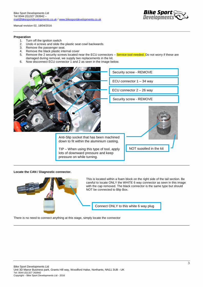
1. Turn off the ignition switch 2. Undo 4 screws and slide the plastic seat cowl backwards. 3. Remove the passenger seat. 4. Remove the black plastic internal cover 5. Remove the 2 security screws located near the ECU connectors – Service tool needed. Do not worry if these are
damaged during removal, we supply two replacements in the kit. 6. Now disconnect ECU connector 1 and 2 as seen in the image below.
Locate the CAN / Diagnostic connector.
This is located within a foam block on the right side of the tail section. Be careful to locate ONLY the WHITE 6 way connector as seen in this image with the cap removed. The black connector is the same type but should NOT be connected to Blip Box.
There is no need to connect anything at this stage, simply locate the connector
Security screw - REMOVE
Security screw - REMOVE
ECU connector 1 – 34 way
ECU connector 2 – 26 way
Anti-Slip socket that has been machined down to fit within the aluminium casting. TIP – When using this type of tool, apply lots of downward pressure and keep pressure on while turning.
Connect ONLY to this white 6 way plug
NOT supplied in the kit

Bike Sport Developments Ltd Tel 0044 (0)1327 263942 – [email protected] / www.bikesportdevelopments.co.uk Manual revision 02, 18/04/2016
4 Bike Sport Developments Ltd Unit 3D Manor Business park, Grants Hill way, Woodford Halse, Northants, NN11 3UB - UK Tel: 0044 (0)1327 263942 Copyright – Bike Sport Developments Ltd - 2016
ECU – Connector 1 – 34 way (right side of bike) – Remove these wires
1. Use a small screwdriver and push IN the white tab on
the underside of the connector. This will push OUT the two white tabs you see protruding in the picture.
2. This releases the lock on the contacts and you only need to pull backwards on a wire to remove it from the housing.
3. Use the image below to help you remove these wires: a. Yellow wire from location 13 b. Yellow / black wire from location 24 c. Green wire from location 5
4. Your connector should now look like the image on the right.
Notes:
Location 5 is the signal ground of the ECU / Twist grip sensor
Location 13 is the Grip 1 signal wire from the sensor
Location 24 is the Grip 2 signal wire from the sensor WARNING – When the white clip has been opened ALL of the contacts will be loose so be careful not to pull on any wires that
you are not working with.
ECU connector 2 – 26 way (centre ECU connector)
This connector contains the signal wire from the shift sensor as we use a ‘Pozi-Tap’ link to link up with this wire.
Locate the green/white shift signal wire in location 20 of the centre 26 way ECU connector. Now position the lower part of the Pozi-Tap over the wire as seen here.
The large red centre section must be fitted the correct way around or the link will not work. Locate the end with the sharp pointed tip protruding from the end of the outer body and screw this end onto the green section until it rests firmly against the wire.
The bike is now ready for the Blip Box wiring to be installed.
Location 5 – Green wire
Location 24 – Yellow/Black wire
Location 13 – Yellow wire
1
10
18
26
Bike Sport Developments Ltd Tel 0044 (0)1327 263942 – [email protected] / www.bikesportdevelopments.co.uk Manual revision 02, 18/04/2016
5 Bike Sport Developments Ltd Unit 3D Manor Business park, Grants Hill way, Woodford Halse, Northants, NN11 3UB - UK Tel: 0044 (0)1327 263942 Copyright – Bike Sport Developments Ltd - 2016
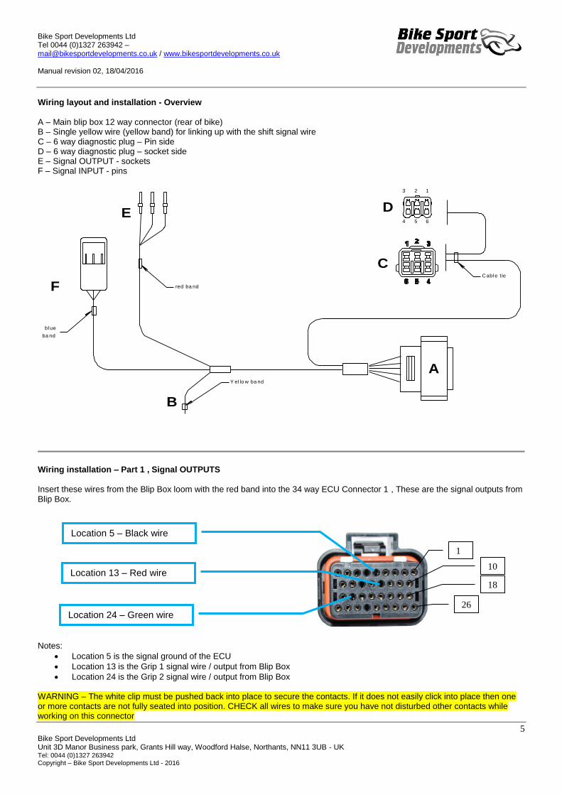
Wiring layout and installation - Overview
A – Main blip box 12 way connector (rear of bike) B – Single yellow wire (yellow band) for linking up with the shift signal wire C – 6 way diagnostic plug – Pin side D – 6 way diagnostic plug – socket side E – Signal OUTPUT - sockets F – Signal INPUT - pins
C abl e t ie
3 2 1
4 5 6
red ba nd
bl ue
ba nd
Y el lo w ba nd
A
B
C
DE
F
Wiring installation – Part 1 , Signal OUTPUTS
Insert these wires from the Blip Box loom with the red band into the 34 way ECU Connector 1 , These are the signal outputs from Blip Box.
Notes:
Location 5 is the signal ground of the ECU
Location 13 is the Grip 1 signal wire / output from Blip Box
Location 24 is the Grip 2 signal wire / output from Blip Box WARNING – The white clip must be pushed back into place to secure the contacts. If it does not easily click into place then one or more contacts are not fully seated into position. CHECK all wires to make sure you have not disturbed other contacts while working on this connector
Location 5 – Black wire
Location 13 – Red wire
Location 24 – Green wire
1
10
18
26

Bike Sport Developments Ltd Tel 0044 (0)1327 263942 – [email protected] / www.bikesportdevelopments.co.uk Manual revision 02, 18/04/2016
6 Bike Sport Developments Ltd Unit 3D Manor Business park, Grants Hill way, Woodford Halse, Northants, NN11 3UB - UK Tel: 0044 (0)1327 263942 Copyright – Bike Sport Developments Ltd - 2016
Connect to this one. WHITE
Wiring installation – Part 2 , Signal INPUTS
This process links up the original signals from the twist grip sensor to the sensor inputs of the Blip Box (white housing with 3 pins)
Blip Box loom (blue band) Colour Kawasaki wiring
Grip 1 input White Yellow Grip 1 – signal
Grip 2 input Yellow Yellow / black Grip 2 – Signal
Ground Black Green Ground from sensor
Locate connector F as seen here
Insert the 3 wires that you removed from the ECU plug into the white housing as you see here and using the wire colour chart above.
Use the white latch cover as seen in this image to secure the contacts in place. Then fix both parts together with the cable tie.
Wiring installation – Part 3 , Shifter load sensor signal
1. Slide the remaining part (locking collar) of the Pozi-Tap red fitting over the single wire with the yellow band.
2. This will leave 5-6mm of exposed inner core of the wire 3. Push this exposed wire into the main body of the Pozi-Tap so it links with the metal
centre 4. Now lock in place by tightening the locking collar 5. The finished connection should look like this image.
Wiring installation – Part 4 , CAN – Data communication
On the right side of the seat cavity you will find the three connectors seen here. Locate the 6 way socket with the WHITE
body. This will connect directly into the Blip Box wiring loom to provide power and data communications with the ECU. Blip Box captures this data over CAN:
Engine RPM
Rear wheel speed
Gear position
Engine power mode
Throttle grip %
Quick shift on/off setting on the dash You will now be left with a 6 way socket connector on the Blip Box wiring for use with the standard Kawasaki diagnostic tool, data loggers, or other expansion devices.

Bike Sport Developments Ltd Tel 0044 (0)1327 263942 – [email protected] / www.bikesportdevelopments.co.uk Manual revision 02, 18/04/2016
7 Bike Sport Developments Ltd Unit 3D Manor Business park, Grants Hill way, Woodford Halse, Northants, NN11 3UB - UK Tel: 0044 (0)1327 263942 Copyright – Bike Sport Developments Ltd - 2016
Wiring installation – Part 5 , Blip Box module
Blip box rests in the tool box tray (sorry no spare room for the tool box) Hold in place using the 3M Dual Lock strip we provide in the kit and the original rubber band. Cable tie wiring as necessary. With the module installed in this way you can easily see the diagnostic and status LED on the box cover.
System ‘power up’
Normal Power on sequence when you turn ON the ignition: 1. LED is solid ON for 2 seconds to indicate power up 2. LED blinks twice to indicate the start of self-calibration. 3. LED blinks 3 times for approximately 10 seconds (3 events of triple blink) , module is self-calibrating and is perfectly
normal 4. LED turns off and will now only activate when the load cell threshold is reached for DOWN shift, or there is a problem. 5. Note that the LED does not activate for UP-Shift as this is still controlled 100% by the ECU.
Normal ignition OFF sequence
1. Blip Box LED is also OFF.
Summary of activation conditions for the Blip to work normally.
System not to be in a diagnostic state
Shift sensor has produced a voltage lower than 2.1 v (2.5v in the unloaded voltage)
The inhibit time must have been exceeded since previous blip shift – Default is 0.20seconds
The load cell must have returned to it’s resting voltage (2.5v) before another blip can occur, remember to take your foot off the lever between shifts.
Engine must be above minimum RPM – Default is 4200rpm
Throttle grip must be lower than threshold (therefore closed) – Default is 3%
Rear wheel speed must be above minimum – Default is 30kmh
QS (quick shift) must be switched ON in your riding mode. Up-Shift output
The up-shift in not controlled in any way by Blip Box, this is all still managed by the standard shift sensor and ECU.
Bike Sport Developments Ltd Tel 0044 (0)1327 263942 – [email protected] / www.bikesportdevelopments.co.uk Manual revision 02, 18/04/2016
8 Bike Sport Developments Ltd Unit 3D Manor Business park, Grants Hill way, Woodford Halse, Northants, NN11 3UB - UK Tel: 0044 (0)1327 263942 Copyright – Bike Sport Developments Ltd - 2016
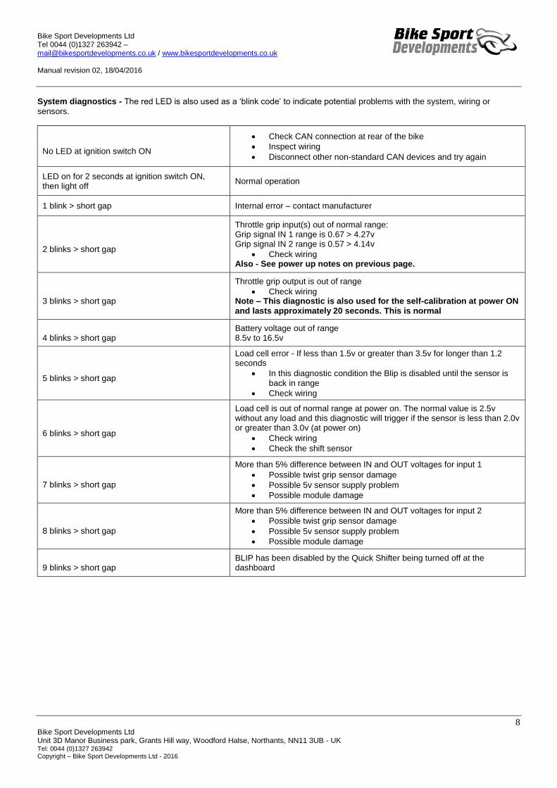
System diagnostics - The red LED is also used as a ‘blink code’ to indicate potential problems with the system, wiring or
sensors.
No LED at ignition switch ON
Check CAN connection at rear of the bike
Inspect wiring
Disconnect other non-standard CAN devices and try again
LED on for 2 seconds at ignition switch ON, then light off
Normal operation
1 blink > short gap Internal error – contact manufacturer
2 blinks > short gap
Throttle grip input(s) out of normal range: Grip signal IN 1 range is 0.67 > 4.27v Grip signal IN 2 range is 0.57 > 4.14v
Check wiring Also - See power up notes on previous page.
3 blinks > short gap
Throttle grip output is out of range
Check wiring Note – This diagnostic is also used for the self-calibration at power ON and lasts approximately 20 seconds. This is normal
4 blinks > short gap
Battery voltage out of range 8.5v to 16.5v
5 blinks > short gap
Load cell error - If less than 1.5v or greater than 3.5v for longer than 1.2 seconds
In this diagnostic condition the Blip is disabled until the sensor is back in range
Check wiring
6 blinks > short gap
Load cell is out of normal range at power on. The normal value is 2.5v without any load and this diagnostic will trigger if the sensor is less than 2.0v or greater than 3.0v (at power on)
Check wiring
Check the shift sensor
7 blinks > short gap
More than 5% difference between IN and OUT voltages for input 1
Possible twist grip sensor damage
Possible 5v sensor supply problem
Possible module damage
8 blinks > short gap
More than 5% difference between IN and OUT voltages for input 2
Possible twist grip sensor damage
Possible 5v sensor supply problem
Possible module damage
9 blinks > short gap
BLIP has been disabled by the Quick Shifter being turned off at the dashboard
Bike Sport Developments Ltd Tel 0044 (0)1327 263942 – [email protected] / www.bikesportdevelopments.co.uk Manual revision 02, 18/04/2016
9 Bike Sport Developments Ltd Unit 3D Manor Business park, Grants Hill way, Woodford Halse, Northants, NN11 3UB - UK Tel: 0044 (0)1327 263942 Copyright – Bike Sport Developments Ltd - 2016
Download the software, drivers and PDF manuals at
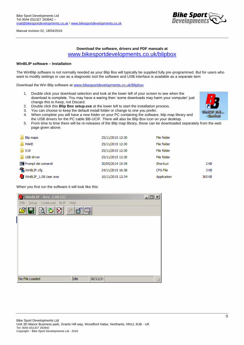
www.bikesportdevelopments.co.uk/blipbox WinBLIP software – Installation
The WinBlip software is not normally needed as your Blip Box will typically be supplied fully pre-programmed. But for users who want to modify settings or use as a diagnostic tool the software and USB interface is available as a separate item
Download the Win Blip software at www.bikesportdevelopments.co.uk/Blipbox
1. Double click your download selection and look at the lower left of your screen to see when the download is complete. You may have a waring then ‘some downloads may harm your computer’ just change this to Keep, not Discard.
2. Double click this Blip Box setup.exe at the lower left to start the installation process.
3. You can choose to keep the default install folder or change to one you prefer. 4. When complete you will have a new folder on your PC containing the software, blip map library and
the USB drivers for the PC cable BB-UCIF. There will also be Blip Box icon on your desktop. 5. From time to time there will be re-releases of the Blip map library, these can be downloaded separately from the web
page given above.
When you first run the software it will look like this:

Bike Sport Developments Ltd Tel 0044 (0)1327 263942 – [email protected] / www.bikesportdevelopments.co.uk Manual revision 02, 18/04/2016
10 Bike Sport Developments Ltd Unit 3D Manor Business park, Grants Hill way, Woodford Halse, Northants, NN11 3UB - UK Tel: 0044 (0)1327 263942 Copyright – Bike Sport Developments Ltd - 2016
USB – PC interface device BB-UCIF
1. PC operating systems from Windows 7 to Windows 10 are OK to use. If you have an older PC with XP then please Email us for specific drivers.
2. Do Not Plug in the USB adapter BB-UCIF yet.
3. Look in the USB drivers folder that has just been installed and
double click the CDM v2.12.06 WHQL Certified.exe file to install the USB drivers. You should do this even if your PC is new and the COM port says it is working correctly, it may not be fully updated.
4. Re-start your PC.
5. Now plug in the USB adapter and wait for up to a minute (sometimes 2) for the drivers to install correctly.
6. To check all is installed correctly open the Control Panel ,
then look for the System icon , then Device Manager to view
this window: This icon shows that the USB adapter is installed and a COM number has been applied. Look at the COM number that has been allocated and make a note of this as it will be used in the WinBLIP software. In this example it is COM6 Note also that you may get a different COM number if using different USB ports on your PC, so try to use the same one each time. Open WinBLIP and go to Setup / COM settings from the upper menu
It should look like this with the Baud Rate at 38400 and the COM line set to the one you noted in the Device manager. If it does not match, use the pull down arrows to change things. Then press OK
Bike Sport Developments Ltd Tel 0044 (0)1327 263942 – [email protected] / www.bikesportdevelopments.co.uk Manual revision 02, 18/04/2016
11 Bike Sport Developments Ltd Unit 3D Manor Business park, Grants Hill way, Woodford Halse, Northants, NN11 3UB - UK Tel: 0044 (0)1327 263942 Copyright – Bike Sport Developments Ltd - 2016
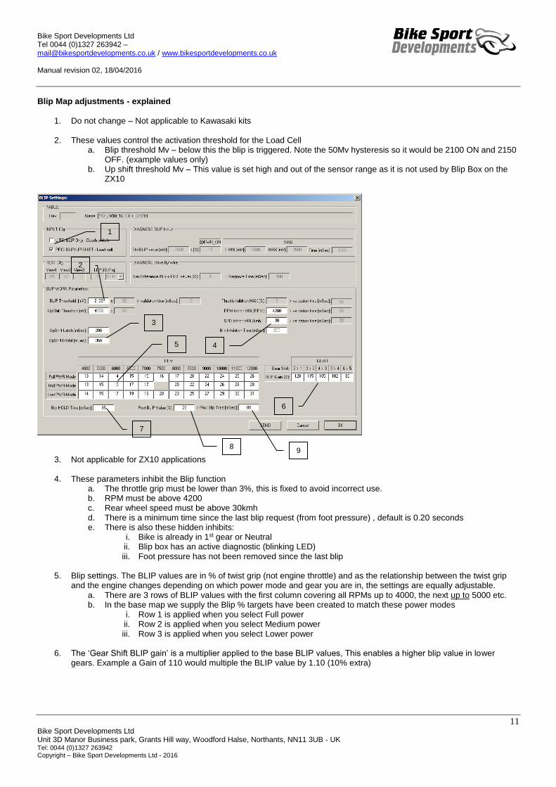
Blip Map adjustments - explained
1. Do not change – Not applicable to Kawasaki kits
2. These values control the activation threshold for the Load Cell
a. Blip threshold Mv – below this the blip is triggered. Note the 50Mv hysteresis so it would be 2100 ON and 2150 OFF. (example values only)
b. Up shift threshold Mv – This value is set high and out of the sensor range as it is not used by Blip Box on the ZX10
3. Not applicable for ZX10 applications
4. These parameters inhibit the Blip function a. The throttle grip must be lower than 3%, this is fixed to avoid incorrect use. b. RPM must be above 4200 c. Rear wheel speed must be above 30kmh d. There is a minimum time since the last blip request (from foot pressure) , default is 0.20 seconds e. There is also these hidden inhibits:
i. Bike is already in 1st gear or Neutral ii. Blip box has an active diagnostic (blinking LED) iii. Foot pressure has not been removed since the last blip
5. Blip settings. The BLIP values are in % of twist grip (not engine throttle) and as the relationship between the twist grip
and the engine changes depending on which power mode and gear you are in, the settings are equally adjustable. a. There are 3 rows of BLIP values with the first column covering all RPMs up to 4000, the next up to 5000 etc. b. In the base map we supply the Blip % targets have been created to match these power modes
i. Row 1 is applied when you select Full power ii. Row 2 is applied when you select Medium power iii. Row 3 is applied when you select Lower power
6. The ‘Gear Shift BLIP gain’ is a multiplier applied to the base BLIP values, This enables a higher blip value in lower
gears. Example a Gain of 110 would multiple the BLIP value by 1.10 (10% extra)
1
2
3
4 5
6
7
8 9

Bike Sport Developments Ltd Tel 0044 (0)1327 263942 – [email protected] / www.bikesportdevelopments.co.uk Manual revision 02, 18/04/2016
12 Bike Sport Developments Ltd Unit 3D Manor Business park, Grants Hill way, Woodford Halse, Northants, NN11 3UB - UK Tel: 0044 (0)1327 263942 Copyright – Bike Sport Developments Ltd - 2016
7. BLIP Hold – This is the primary BLIP duration and will be of a height equal to the BLIP value from the table x the BLIP GEAR Gain (explained in 6 above)
a. The primary blip is short and fast to rapidly raise the engine RPM and disengage the gearbox pressure from braking to accelerating.
b. There is then a ‘post blip’ with a height of x
% (parameter 8) of the primary blip and continuing on for x mSec (parameter 9). This
keeps the RPM sufficiently high after the blip to match the RPM of the next gear selected.
c. The image at the right shows the 2 stages of BLIP and the perfectly matched RPM values.
d. You can also see the 2 stages of the blip in the middle data trace called GRIP_ECU
WinBLIP - View Data From the upper menu select BLIP / View data to get the following live data screen.
1. Firmware version of the Blip Box module – For the Kawasaki this will read 1.12b 2. File name currently loaded into the module 3. These icons will light up when the voltage thresholds are exceeded for DOWN shift
1 2
3
4
5
6
7
3
4
5
6
7
Bike Sport Developments Ltd Tel 0044 (0)1327 263942 – [email protected] / www.bikesportdevelopments.co.uk Manual revision 02, 18/04/2016
13 Bike Sport Developments Ltd Unit 3D Manor Business park, Grants Hill way, Woodford Halse, Northants, NN11 3UB - UK Tel: 0044 (0)1327 263942 Copyright – Bike Sport Developments Ltd - 2016
4. These icons will light up if either the front or rear brake is applied (not applicable for ZX10 – Ignore the icons) 5. These icons will light up if the BLIP is currently inhibited by one or more reasons 6. Live data:
a. Throttle grip 1 – Input Mv b. Throttle grip 2 – Input Mv c. Load cell – Mv d. Load cell offset (self calibration adjustment after power ON) e. Engine power mode 1 > 4 f. Engine RPM g. TPS (Throttle grip %) h. GEAR (0 is neutral) i. Rear wheel speed in kmh
7. These icons will light up if one of the diagnostic (flashing LED) is active. 8. Restart – system re-start, not normally needed by the user. Used in case of power sleep mode and bench testing.
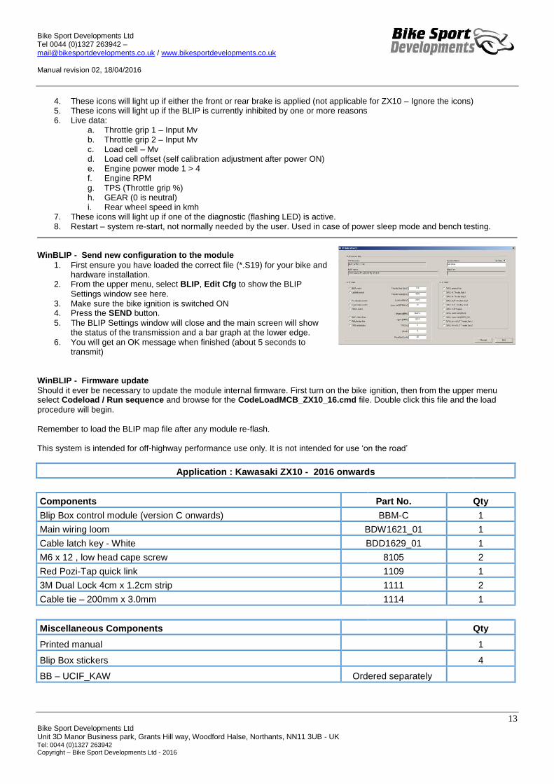
WinBLIP - Send new configuration to the module
1. First ensure you have loaded the correct file (*.S19) for your bike and hardware installation.
2. From the upper menu, select BLIP, Edit Cfg to show the BLIP
Settings window see here. 3. Make sure the bike ignition is switched ON 4. Press the SEND button.
5. The BLIP Settings window will close and the main screen will show the status of the transmission and a bar graph at the lower edge.
6. You will get an OK message when finished (about 5 seconds to transmit)
WinBLIP - Firmware update
Should it ever be necessary to update the module internal firmware. First turn on the bike ignition, then from the upper menu select Codeload / Run sequence and browse for the CodeLoadMCB_ZX10_16.cmd file. Double click this file and the load
procedure will begin. Remember to load the BLIP map file after any module re-flash. This system is intended for off-highway performance use only. It is not intended for use ‘on the road’
Application : Kawasaki ZX10 - 2016 onwards
Components Part No. Qty
Blip Box control module (version C onwards) BBM-C 1
Main wiring loom BDW1621_01 1
Cable latch key - White BDD1629_01 1
M6 x 12 , low head cape screw 8105 2
Red Pozi-Tap quick link 1109 1
3M Dual Lock 4cm x 1.2cm strip 1111 2
Cable tie – 200mm x 3.0mm 1114 1
Miscellaneous Components Qty
Printed manual
1
Blip Box stickers
4
BB – UCIF_KAW Ordered separately

Bike Sport Developments Ltd Tel 0044 (0)1327 263942 – [email protected] / www.bikesportdevelopments.co.uk Manual revision 02, 18/04/2016
14 Bike Sport Developments Ltd Unit 3D Manor Business park, Grants Hill way, Woodford Halse, Northants, NN11 3UB - UK Tel: 0044 (0)1327 263942 Copyright – Bike Sport Developments Ltd - 2016
Bike Sport Developments Ltd The Old Barn, Greatworth Hall, Greatworth, Oxon, OX17 2DH - UK
Tel: 0044 (0)1327 263942
www.bikesportdevelopments.co.uk
Download the software, drivers and PDF manuals at
www.bikesportdevelopments.co.uk/blipbox


![GR-2994 British Columbia. Supreme Court (Courtenay)...[Jim][Jimmy][Edward] 1987 830397-0044 CO878043 Robinson, John 1987 830397-0044 CO878044 Mjooney, Gladys Margaret 1987 830397-0044](https://img.pdfslide.us/doc/110x75/6052e922e026413ecf79de08/gr-2994-british-columbia-supreme-court-courtenay-jimjimmyedward-1987.jpg)