Embed Size (px)
Citation preview

KAWASAKIMOTOS.COM.AR

Black plate (1,1)
ENGLISH
WatercraftOwner's Manual
Original instructions

Black plate (2,1)

Black plate (3,1)

Black plate (4,1)

Black plate (5,1)
Read This First!Congratulations on purchasing a new Kawasaki
JET SKI watercraft.Your safety and the safety of other people is very
important. The operator of the JET SKI watercraft isresponsible for operating it safely.This Owner’s Manual explains how to operate the
JET SKI watercraft properly to protect you and otherpeople from injury. The first part of this manual,
and the instructions under “ DANGER” and
“ WARNING” in the main text are particularlyimportant for ensuring safety. Please read themcarefully and be sure to follow the warnings andinstructions.
Safety alert symbols
These safety symbols alert the user to a possiblehuman risk.Be sure to follow all safety instructions that follow
these symbols to avoid accidents that could result inpersonal injury or death.
Precautionary statementsThese warnings indicate situations that could re-
sult in death or serious injury of the rider or otherpersons involved, or damage to the watercraft, andinstructions on how to avoid them. The followingsymbols are used to indicate the seriousness of thedanger.
DANGERDANGER indicates a hazardous situationwhich, if not avoided, will result in death orserious injury.
WARNINGWARNING indicates a hazardous situationwhich, if not avoided, could result in death orserious injury.
NOTICENOTICE is used to address practices not re-lated to personal injury.
NOTE○NOTE indicates information that may help orguide you in the operation or service of the ve-hicle.
Black plate (6,1)
About This ManualPlease keep this Owner's Manual for future refer-
ence. If you resell or transfer your JET SKI water-craft, be sure to provide this manual with theproduct.
Keep this Owner's Manual aboard your JET SKIwatercraft in a waterproof bag at all times so thatyou can refer to it whenever necessary.
The information in this Owner's Manual may notcompletely match the actual product due to changesin the specifications.
Design CategoryThis watercraft belongs to # Category C and is de-signed to operate in winds up to Beaufort force 6and the associated wave heights (significant waveheight up to 2 m, see NOTE below). Such conditionsmay also be encountered in exposed inland waters,in estuaries, and in coastal waters in moderateweather conditions.
NOTE○The significant wave height is the mean height ofthe highest one-third of the waves, which corre-sponds to the wave height estimated by an expe-rienced observer. Some waves will be double thisheight.
**********************************************************
is a trademark of Kawa-saki Heavy Industries, Ltd. registered in U.S.A.,Japan, Austria, Benelux, Sweden, Denmark,Switzerland, France, Canada, Finland, Norway,Greece, Italy, U.K., Portugal, Thailand, and Tai-wan.
KAWASAKI JET SKI is a trademark of Kawasa-ki Heavy Industries, Ltd. registered in Australia.
All rights reserved. No part of this publication maybe reproduced without our prior written permission.
© 2016 Kawasaki HeavyIndustries, Ltd.
Nov. 8, 2016. (1)
Black plate (7,1)
Quick Reference Guide
This Quick Reference Guide will assist you infinding the information you're looking for.
A Table of Contents is included after the Foreword.
SAFETY INFORMATION
PREVENT MAJOR DAMAGE
GENERAL INFORMATION
PRE-RIDE CHECK
OPERATING INSTRUCTIONS
TRANSPORTING AND STORAGE
MAINTENANCE AND ADJUSTMENTS
IN AN EMERGENCY
APPENDIX
MAINTENANCE RECORD

Black plate (8,1)
TABLE OF CONTENTS
SAFETY INFORMATION .............................. 10Read Owner’s Manual Thoroughly beforeOperation ....................................................... 10
Wear PFD, Protective Clothing and Gear ........ 10Personal Flotation Device (PFD) ................... 10Wet Suit Bottoms or Other ProtectiveClothing ...................................................... 11
Other Protective Gear ................................... 11Know Boating Laws .......................................... 12Occupants and Load Limit ............................... 12Attach Engine Shut-Off Cord (Lanyard) ........... 13Ride within Your Limits ..................................... 13Do not Jump Wakes or Waves ......................... 14Never Ride after Consuming Drugs or Alcohol 14Do not Apply Throttle when Anyone is Behind . 15Keep Away from Intake Grate .......................... 15Avoid Forceful Jet Thrust and Limited Visibilitywhile Reboarding .......................................... 16
Avoid Collision .................................................. 16Ventilate Engine Compartment ........................ 18Keep Your Watercraft in Safe Condition ........... 18Pre-Ride Check ............................................. 18Regular Maintenance/Modification ................ 18
Never Operate after Dark ................................. 19Follow Rules ..................................................... 20Label Location .................................................. 20
PREVENT MAJOR DAMAGE ............................ 26Tilting the Watercraft ........................................ 27Righting Capsized Watercraft .......................... 27Shallow Water .................................................. 28Wave Jumping .................................................. 28
After Daily Riding .............................................. 29Jet Pump Bearings and Seals PeriodicMaintenance .................................................. 29
GENERAL INFORMATION ................................ 30Parts Location .................................................. 30Indicator Lights ................................................. 32Fuel Level Warning Indicator Light (Amber) .. 32Engine Warning Indicator Light (Red) ........... 33
Fuel ................................................................... 33Fuel Requirements ........................................ 33Filling the Tank .............................................. 34
Ignition Switch .................................................. 36Controls ............................................................ 38Stop Button .................................................... 38Engine Shut-off Lanyard Key ........................ 39Starter Interlock Switch ................................. 39Start Button .................................................... 40Throttle Lever ................................................ 40
Storage Cover .................................................. 41Engine Cover .................................................... 42Tool Kit .............................................................. 46Bilge Systems ................................................... 47Drain Screws .................................................... 47Loading/Accessories/Modifications .................. 48Maximum load ............................................... 48
Towing .............................................................. 49Towing a personal watercraft ........................ 49
PRE-RIDE CHECK ............................................. 50OPERATING INSTRUCTIONS ........................... 52Basic Knowledge for Operation ........................ 52Operation by unskilled riders ......................... 52

Black plate (9,1)
Operator Swimming Ability ............................. 52Maximum Number of Person ......................... 52Safe Riding Rules ........................................... 52Personal Flotation Device and Safety Gear ... 52Watercraft Helmet..... Something You ShouldKnow ........................................................... 54
Fire Extinguisher ............................................ 54Weather condition ............................................. 55Basic Operating and Riding .............................. 56Posture on the Riding Platform ...................... 56Standing Up .................................................... 56Break-In .......................................................... 57Stopping the Engine ....................................... 57Starting the Engine ......................................... 58
Launching .......................................................... 62Launching/Start .............................................. 62Stopping the JET SKI Watercraft ................... 65Turning the JET SKI Watercraft ...................... 67Docking the JET SKI Watercraft ..................... 70Fall Recovery ................................................. 71Righting the Capsized Watercraft .................. 71After Submerging ........................................... 72
End of the Day Checklist ................................... 76Drain the Exhaust System .............................. 76Clean the Engine Compartment ..................... 77Clearing Clogged Impeller .............................. 78
TRANSPORTING AND STORAGE .................... 80Transporting ...................................................... 80STORAGE ......................................................... 81Preparation for Storage .................................. 81Removal from Storage ................................... 86
MAINTENANCE AND ADJUSTMENTS ............. 89EMISSION CONTROL INFORMATION ............ 90Periodic Maintenance Chart .............................. 92
Control Cables ................................................... 94Fuel System ...................................................... 97Throttle Adjustments ...................................... 97Fuel Vent Check Valve ................................... 97Fuel Pump Screen .......................................... 97Fuel Hose ....................................................... 97
Engine Oil .......................................................... 98Oil Requirements ............................................ 98Oil Level Inspection ........................................ 99Oil Change .....................................................101
Spark Plugs .......................................................103Battery ...............................................................106Lubrication .........................................................119Cooling System Flushing ..................................121Bilge System Flushing .......................................123Jet Pump Bearings/Seals ..................................124Fuses .................................................................125IN AN EMERGENCY ......................................126
Troubleshooting Guide ......................................126In the Case of Emergency .................................130Towing the JET SKI watercraft .......................130Jump Starting .................................................130
APPENDIX ...........................................................132ENVIRONMENTAL PROTECTION ..................132SPECIFICATIONS ............................................133Serial Numbers ..................................................136Registration Numbers .......................................137
MAINTENANCE RECORD ..................................139

Black plate (10,1)
SAFETY INFORMATIONWARNING
Read Owner’s Manual Thoroughlybefore Operation
• Carefully read the instructions in every WARNINGmessage in the owner’s manual and on everywarning label on your JET SKI watercraft beforeoperating. Be sure to observe these instructions.
• The owner’s manual and the warning labels pro-vide important safety information.
Wear PFD, Protective Clothing andGear
Personal Flotation Device (PFD)
• All riders must wear a personal flotation device(PFD) that is suitable for personal watercraft(PWC) use. Kawasaki recommends a vest-typePFD.Hard impact with the water can result in loss of
consciousness and drowning.
• Make sure that your PFD fits correctly so that itdoes not come off in the water. Never use an adultsize PFD for children.
10 SAFETY INFORMATION Important. Read this carefully.
Black plate (11,1)
Wet Suit Bottoms or Other Protective Clothing
• All riders must wear wet suit bottoms (neopreneshorts) or clothing that provides equivalent protec-tion against possible injury to body cavities.
• Normal swimwear will not provide adequate pro-tection.
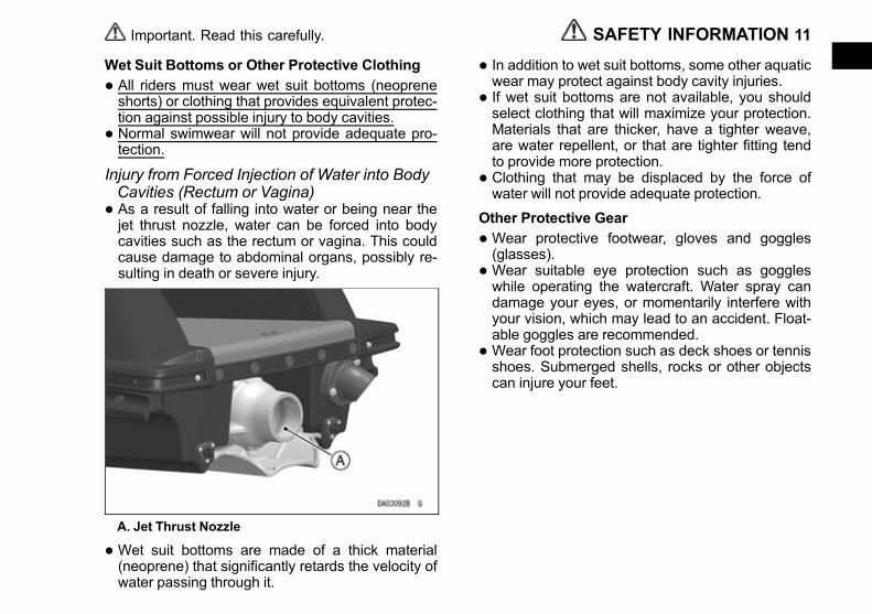
Injury from Forced Injection of Water into BodyCavities (Rectum or Vagina)• As a result of falling into water or being near thejet thrust nozzle, water can be forced into bodycavities such as the rectum or vagina. This couldcause damage to abdominal organs, possibly re-sulting in death or severe injury.
A. Jet Thrust Nozzle
• Wet suit bottoms are made of a thick material(neoprene) that significantly retards the velocity ofwater passing through it.
• In addition to wet suit bottoms, some other aquaticwear may protect against body cavity injuries.
• If wet suit bottoms are not available, you shouldselect clothing that will maximize your protection.Materials that are thicker, have a tighter weave,are water repellent, or that are tighter fitting tendto provide more protection.
• Clothing that may be displaced by the force ofwater will not provide adequate protection.
Other Protective Gear
• Wear protective footwear, gloves and goggles(glasses).
• Wear suitable eye protection such as goggleswhile operating the watercraft. Water spray candamage your eyes, or momentarily interfere withyour vision, which may lead to an accident. Float-able goggles are recommended.
• Wear foot protection such as deck shoes or tennisshoes. Submerged shells, rocks or other objectscan injure your feet.
SAFETY INFORMATION 11Important. Read this carefully.
Black plate (12,1)
Know Boating Laws
• Kawasaki recommends a minimum operator ageof 16 years old. Know the operator age and train-ing requirements for your state or region. A boat-ing safety course is recommended and may berequired in your state or region.
Occupants and Load Limit
Occupants limit 1 person
Load limit 75 kg (165 lb) including riderand luggage
• Exceeding the maximum number of occupant orthe load limit can adversely affect the handlingand stability of this watercraft, which can lead toan accident. Do not exceed the maximum ca-pacity.
12 SAFETY INFORMATION Important. Read this carefully.
Black plate (13,1)
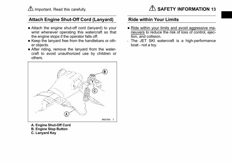
Attach Engine Shut-Off Cord (Lanyard)
• Attach the engine shut-off cord (lanyard) to yourwrist whenever operating this watercraft so thatthe engine stops if the operator falls off.
• Keep the lanyard free from the handlebars or oth-er objects.
• After riding, remove the lanyard from the water-craft to avoid unauthorized use by children orothers.
A. Engine Shut-Off CordB. Engine Stop ButtonC. Lanyard Key
Ride within Your Limits
• Ride within your limits and avoid aggressive ma-neuvers to reduce the risk of loss of control, ejec-tion, and collision.
- The JET SKI watercraft is a high-performanceboat - not a toy.
SAFETY INFORMATION 13Important. Read this carefully.
Black plate (14,1)
Do not Jump Wakes or Waves
• Sharp turns or jumping wakes or waves can in-crease the risk of back/spinal injury (paralysis), fa-cial injuries, and broken legs, ankles and otherbones.
Never Ride after Consuming Drugs orAlcohol
• Never ride under the influence of or after consum-ing drugs or alcohol.
14 SAFETY INFORMATION Important. Read this carefully.
Black plate (15,1)
Do not Apply Throttle when Anyone isBehind
• Do not apply throttle when anyone is behind theJET SKI watercraft.
- Turn the engine off or keep it at idle. Water and/ordebris ejected from the jet thrust nozzle can causesevere injury.
Keep Away from Intake Grate
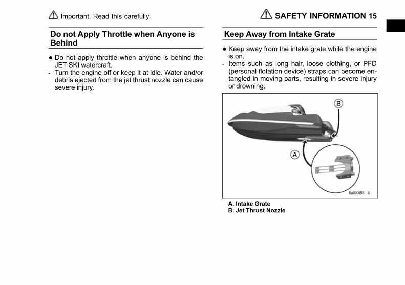
• Keep away from the intake grate while the engineis on.
- Items such as long hair, loose clothing, or PFD(personal flotation device) straps can become en-tangled in moving parts, resulting in severe injuryor drowning.
A. Intake GrateB. Jet Thrust Nozzle
SAFETY INFORMATION 15Important. Read this carefully.
Black plate (16,1)
Avoid Forceful Jet Thrust and LimitedVisibility while Reboarding
• Get to a standing or kneeling position quickly, butdo not expose yourself to forceful jet thrust.
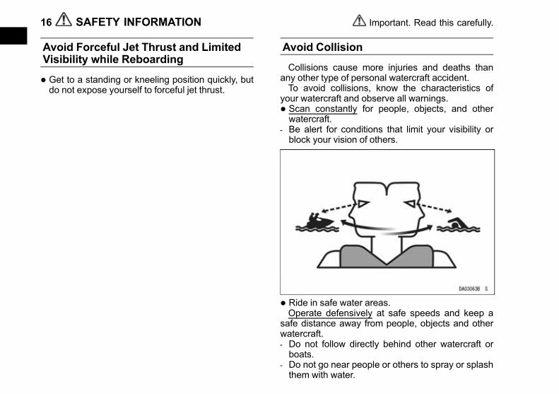
Avoid Collision
Collisions cause more injuries and deaths thanany other type of personal watercraft accident.To avoid collisions, know the characteristics of
your watercraft and observe all warnings.
• Scan constantly for people, objects, and otherwatercraft.
- Be alert for conditions that limit your visibility orblock your vision of others.
• Ride in safe water areas.Operate defensively at safe speeds and keep a
safe distance away from people, objects and otherwatercraft.- Do not follow directly behind other watercraft orboats.
- Do not go near people or others to spray or splashthem with water.
16 SAFETY INFORMATION Important. Read this carefully.
Black plate (17,1)
- Avoid sharp turns or other maneuvers that make ithard for others to avoid you or understand whereyou are going.
- Avoid areas with submerged objects or shallowwaters.
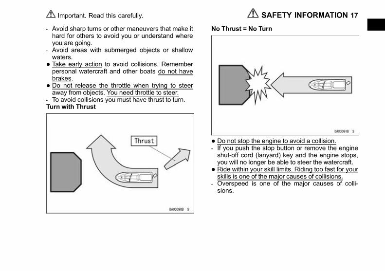
• Take early action to avoid collisions. Rememberpersonal watercraft and other boats do not havebrakes.
• Do not release the throttle when trying to steeraway from objects. You need throttle to steer.
- To avoid collisions you must have thrust to turn.Turn with Thrust
No Thrust = No Turn
• Do not stop the engine to avoid a collision.- If you push the stop button or remove the engineshut-off cord (lanyard) key and the engine stops,you will no longer be able to steer the watercraft.
• Ride within your skill limits. Riding too fast for yourskills is one of the major causes of collisions.
- Overspeed is one of the major causes of colli-sions.
SAFETY INFORMATION 17Important. Read this carefully.

Black plate (18,1)
Ventilate Engine Compartment
• Open the engine compartment to ventilate it be-fore starting the engine. A concentration of gaso-line fumes can cause a fire or explosion. Do notstart the engine if there is a fuel leak or gasolinefumes.
• Before each ride, and after refueling or transporta-tion, ventilate the engine compartment for severalminutes with the engine cover removed.
Keep Your Watercraft in Safe Condition
Pre-Ride Check
• Check the throttle lever and steering system(Handlebars and Steering Nozzle) for proper op-eration before riding the watercraft.
A. Throttle LeverB. Steering Nozzle (Jet Thrust Nozzle)
• Check the battery, fuel, oil and other items in thePre-Ride Checklist of this owner’s manual.
Regular Maintenance/Modification
• Maintain your watercraft for safe operation by car-rying out all maintenance items in the MAINTE-NANCE AND ADJUSTMENTS section of thisowner's manual.
18 SAFETY INFORMATION Important. Read this carefully.

Black plate (19,1)
• Modifications to your watercraft may affect itsstability or handling, and result in an unsafe ridingcondition or illegal condition for use. Do not usenon-Kawasaki Parts and Accessories on yourwatercraft.
Never Operate after Dark
• Do not operate the watercraft after dark. It is notdesigned for night use, and has no lighting equip-ment.
SAFETY INFORMATION 19Important. Read this carefully.

Black plate (20,1)
Follow Rules
• Follow all navigation rules and state and locallaws that apply to PWCs.
Label Location
All warning labels on the vehicle are repeatedhere. Read the labels and understand them thor-oughly. They contain information that is importantfor your safety and the safety of anyone else whomay operate your vehicle. Therefore, it is very im-portant that all warning labels be on your vehicle inthe locations shown. If any label is missing, dam-aged, or worn, get a replacement from your Kawa-saki dealer and install it in the correct position.
NOTE○The sample warning labels in this section havepart numbers to help you obtain the correct re-placement.
20 SAFETY INFORMATION Important. Read this carefully.

Black plate (21,1)
(A)
Use fuel identified by either of the above sym-bols.
1. Gasoline containing up to 5% ethanol by vol-ume
2. Gasoline containing up to 10% ethanol by vol-ume
See page 34.
SAFETY INFORMATION 21Important. Read this carefully.
Black plate (22,1)
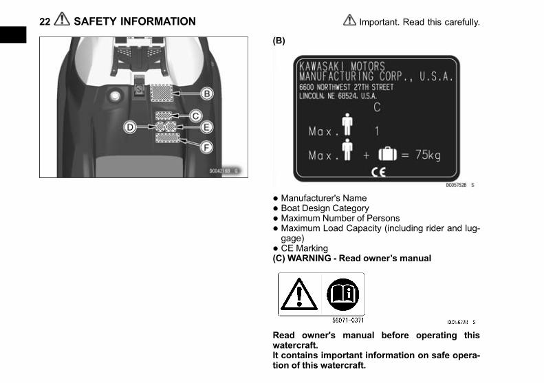
(B)
• Manufacturer's Name
• Boat Design Category
• Maximum Number of Persons
• Maximum Load Capacity (including rider and lug-gage)
• CE Marking(C) WARNING - Read owner’s manual
Read owner's manual before operating thiswatercraft.It contains important information on safe opera-tion of this watercraft.
22 SAFETY INFORMATION Important. Read this carefully.
Black plate (23,1)
(D) Instruction - Wear swimvest
Swimvest must be worn by operator.(E) Instruction - Attatch lanyard
Keep the engine shut-off lanyard attached to theoperator at all times while operating the boat.If operator falls off boat with engine shut-off lan-yard unattached, the boat will not stop. Thiscould cause the operator to become stranded inthe water, and/or the boat to hit another boat orperson.
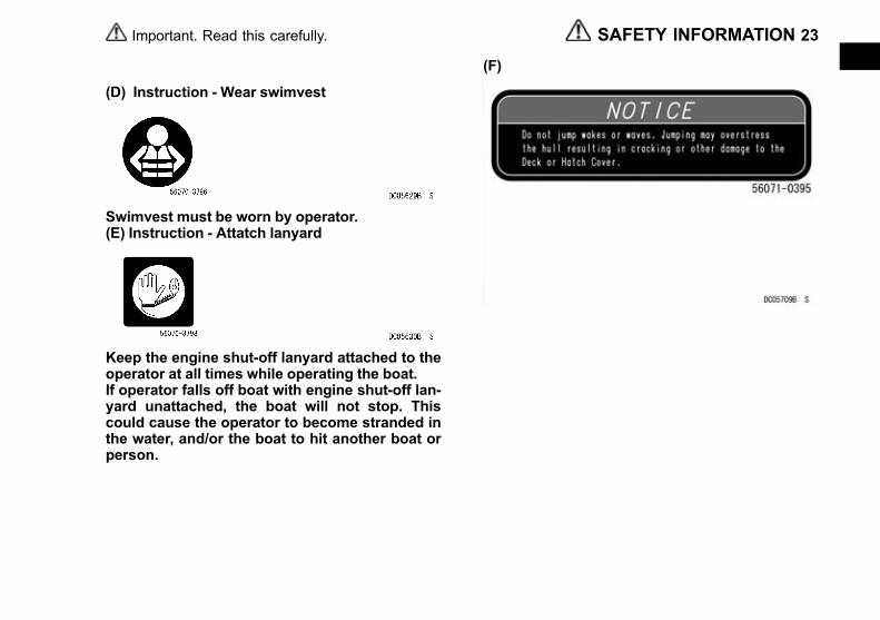
(F)
SAFETY INFORMATION 23Important. Read this carefully.

Black plate (24,1)
(G) Battery Danger/Poison (H) Manufacture
24 SAFETY INFORMATION Important. Read this carefully.

Black plate (25,1)
(I) Righting the Capsized Watercraft, see page 71
SAFETY INFORMATION 25Important. Read this carefully.

Black plate (26,1)
PREVENT MAJOR DAMAGENOTICE
Certain conditions can cause major damage to your watercraft that is costly to repair. To avoid these condi-tions carefully read the following section and follow the recommendations to help prevent major damage to yourwatercraft.
26 PREVENT MAJOR DAMAGE

Black plate (27,1)
Tilting the Watercraft
• Tilting the watercraft to its STARBOARD side cancause water in the exhaust system to run into theengine, with possible engine damage. Always tiltthe boat on its PORT side if it is necessary to in-spect the bottom of the craft.
Righting Capsized Watercraft
• Rolling the capsized watercraft counterclockwise(to its STARBOARD side) can cause water in theexhaust system to run into the engine, with possi-ble engine damage. Always turn the capsizedboat clockwise so that the PORT side alwaysfaces downward.
• For details on righting, refer to Righting the Cap-sized Watercraft section in the OPERATING IN-STRUCTIONS chapter.
PREVENT MAJOR DAMAGE 27
Black plate (28,1)
Shallow Water
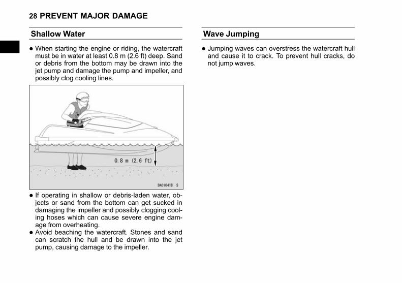
• When starting the engine or riding, the watercraftmust be in water at least 0.8 m (2.6 ft) deep. Sandor debris from the bottom may be drawn into thejet pump and damage the pump and impeller, andpossibly clog cooling lines.
• If operating in shallow or debris-laden water, ob-jects or sand from the bottom can get sucked indamaging the impeller and possibly clogging cool-ing hoses which can cause severe engine dam-age from overheating.
• Avoid beaching the watercraft. Stones and sandcan scratch the hull and be drawn into the jetpump, causing damage to the impeller.
Wave Jumping
• Jumping waves can overstress the watercraft hulland cause it to crack. To prevent hull cracks, donot jump waves.
28 PREVENT MAJOR DAMAGE

Black plate (29,1)
After Daily Riding
• Remove JET SKI watercraft from the water at theend of each day’s use.
• Since JET SKI watercraft are not designed to bedocked in water for extended periods, prolongedimmersion will cause the hull paint to bubble andpeel, as well as electrolytic erosion of some metalparts in the jet pump. To prevent this damage andelectrolytic erosion, remove your JET SKI water-craft from the water at the end of each day’s use;do not leave it in the water overnight. Your JETSKI watercraft will last longer and look better ifyou do this.
Jet Pump Bearings and Seals PeriodicMaintenance
• The jet pump bearings and seals require periodicservice. Major engine damage can occur if the jetpump bearings fail due to lack of maintenance.Have your Kawasaki dealer inspect the jet pumpbearings and seals after the first 25 hours of useor after one year, whichever comes first; and thenevery 50 hours or every year, whichever comesfirst. The jet pump bearings should also be serv-iced before any prolonged storage to prevent anywater that may be left in the pump from corrodingthe bearings and causing premature failure.
PREVENT MAJOR DAMAGE 29
Black plate (30,1)
GENERAL INFORMATION
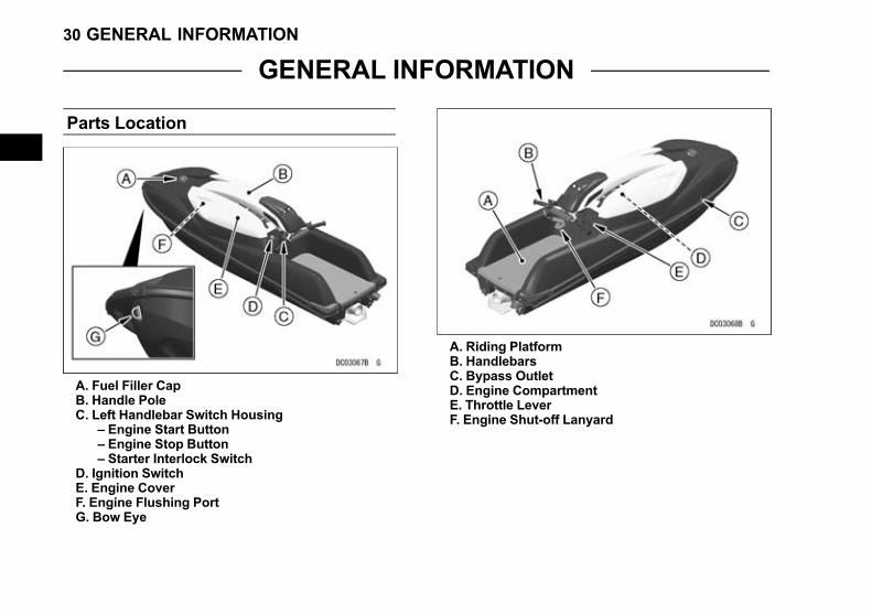
Parts Location
A. Fuel Filler CapB. Handle PoleC. Left Handlebar Switch Housing
– Engine Start Button– Engine Stop Button– Starter Interlock Switch
D. Ignition SwitchE. Engine CoverF. Engine Flushing PortG. Bow Eye
A. Riding PlatformB. HandlebarsC. Bypass OutletD. Engine CompartmentE. Throttle LeverF. Engine Shut-off Lanyard
30 GENERAL INFORMATION

Black plate (31,1)
A. Drain ScrewsB. Steering NozzleC. Exhaust Outlet
A. Jet Pump CoverB. Water IntakeC. GrateD. Drive Shaft
GENERAL INFORMATION 31
Black plate (32,1)
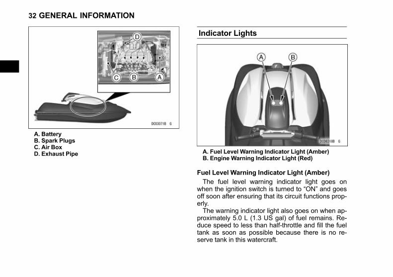
A. BatteryB. Spark PlugsC. Air BoxD. Exhaust Pipe
Indicator Lights
A. Fuel Level Warning Indicator Light (Amber)B. Engine Warning Indicator Light (Red)
Fuel Level Warning Indicator Light (Amber)
The fuel level warning indicator light goes onwhen the ignition switch is turned to “ON” and goesoff soon after ensuring that its circuit functions prop-erly.The warning indicator light also goes on when ap-
proximately 5.0 L (1.3 US gal) of fuel remains. Re-duce speed to less than half-throttle and fill the fueltank as soon as possible because there is no re-serve tank in this watercraft.
32 GENERAL INFORMATION
Black plate (33,1)
Engine Warning Indicator Light (Red)
The engine warning indicator light goes on whenthe ignition switch is turned to “ON” and goes offsoon after ensuring that its circuit functions properly.The engine warning indicator light also blinks
when the DFI system has malfunctioned. Return toshore immediately and have an authorized Kawasa-ki JET SKI watercraft dealer check your watercraftto determine the problem.
Fuel
NOTICEThis watercraft has not been tested and certi-fied for use with racing fuels or fuel additives.Their use may damage the engine and fuelsystem. Do not use race gas or fuel additives.
Fuel Requirements
Your Kawasaki engine is designed to use only un-leaded gasoline with a minimum octane ratingshown below. Never use gasoline with an octanerating lower than the minimum specified by Kawasa-ki to prevent severe engine damage.The octane rating of a gasoline is a measure of its
resistance to detonation or “knocking.” The termcommonly used to describe a gasoline’s octane rat-ing is the Research Octane Number (RON).
GENERAL INFORMATION 33

Black plate (34,1)
NOTICEEngine “knocking” or “pinging” can lead tosevere engine damage. If engine “knocking”or “pinging” occurs, use a different brand ofgasoline of a higher octane rating.Gasoline quality is important. Fuels of lowquality or not meeting standard industryspecifications may result in unsatisfactoryperformance. Operating problems that resultfrom the use of poor quality or nonrecom-mended fuel may not be covered under yourwarranty.
Fuel Type and Octane RatingUse clean, fresh unleaded gasoline with an oc-
tane rating equal to or higher than that shown in thetable.
Fuel Type Unleaded Gasoline
Ethanol Con-tent
E10 or less
MinimumOctane Rating
Research Octane Number (RON)91
NOTICEDamage to the engine and fuel system, or en-gine starting and/or performance problemsmay result from the use of improper fuel. Donot use any fuel that contains more ethanolor other oxygenates than specified for E10fuel* in this vehicle.
*E10 means fuel containing up to 10% ethanol asspecified by European directive.
Filling the Tank
WARNINGGasoline is extremely flammable and can beexplosive under certain conditions. To avoida possible fire or explosion, pull the lanyardkey off the stop button. Do not smoke. Makesure the area is well ventilated and free fromany source of flame or sparks; this includesany appliance with a pilot light.
Avoid filling the tank in the rain or where heavydust is blowing so that the fuel does not get contami-nated.The fuel tank and the fuel filler cap are located at
the front end of the engine compartment. Turn thecap counterclockwise and remove it.
34 GENERAL INFORMATION
Black plate (35,1)
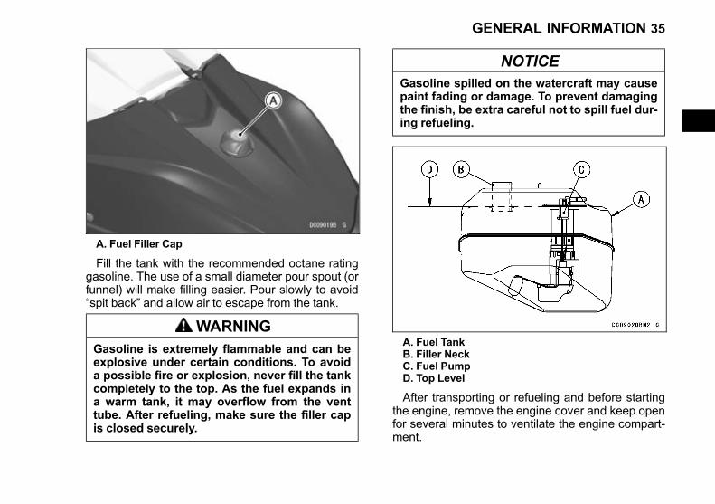
A. Fuel Filler Cap
Fill the tank with the recommended octane ratinggasoline. The use of a small diameter pour spout (orfunnel) will make filling easier. Pour slowly to avoid“spit back” and allow air to escape from the tank.
WARNINGGasoline is extremely flammable and can beexplosive under certain conditions. To avoida possible fire or explosion, never fill the tankcompletely to the top. As the fuel expands ina warm tank, it may overflow from the venttube. After refueling, make sure the filler capis closed securely.
NOTICEGasoline spilled on the watercraft may causepaint fading or damage. To prevent damagingthe finish, be extra careful not to spill fuel dur-ing refueling.
A. Fuel TankB. Filler NeckC. Fuel PumpD. Top Level
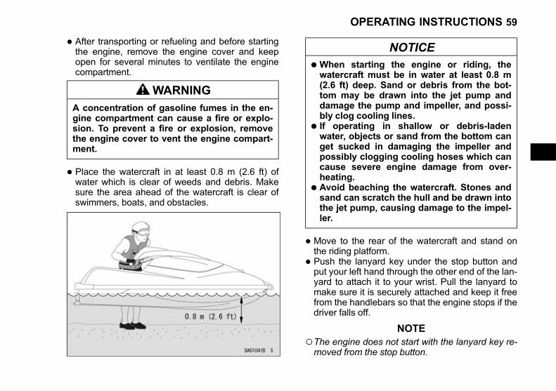
After transporting or refueling and before startingthe engine, remove the engine cover and keep openfor several minutes to ventilate the engine compart-ment.
GENERAL INFORMATION 35

Black plate (36,1)
WARNINGA concentration of gasoline fumes in the en-gine compartment can cause a fire or explo-sion. To prevent a fire or explosion, removethe engine cover to vent the engine compart-ment.
Ignition Switch
The ignition switch is located on the left side of thedeck under the handlebars. It is a 2-position, key op-erated switch. The key can be removed when in the“OFF” and “ON” positions.Remove the key immediately after turning the igni-
tion switch on and store it in the storage cover underthe handle pole.Be sure to turn the ignition switch off after stop-
ping the engine to prevent the battery from discharg-ing. Whenever the watercraft is not in use, turn thekey “OFF” and remove it to prevent unauthorizeduse.
A. Ignition SwitchB. ON PositionC. OFF Position
36 GENERAL INFORMATION

Black plate (37,1)
NOTICEAfter turning the ignition switch “ON,” re-move the key. Stow it in a secure place on thewatercraft or with you while riding.Always turn the ignition switch “OFF” afterstopping the engine to prevent the batteryfrom discharging.
A. KeyB. Key Number
Record your ignition key number. In the event ofloss of the key, ask your dealer to get the same keynumber.
Write your key number here.
GENERAL INFORMATION 37
Black plate (38,1)
Controls
Handlebars
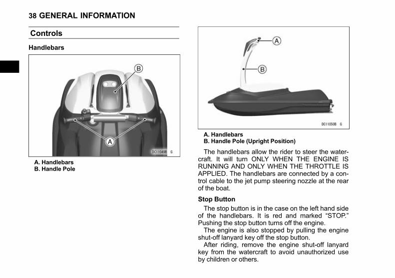
A. HandlebarsB. Handle Pole
A. HandlebarsB. Handle Pole (Upright Position)
The handlebars allow the rider to steer the water-craft. It will turn ONLY WHEN THE ENGINE ISRUNNING AND ONLY WHEN THE THROTTLE ISAPPLIED. The handlebars are connected by a con-trol cable to the jet pump steering nozzle at the rearof the boat.
Stop Button
The stop button is in the case on the left hand sideof the handlebars. It is red and marked “STOP.”Pushing the stop button turns off the engine.The engine is also stopped by pulling the engine
shut-off lanyard key off the stop button.After riding, remove the engine shut-off lanyard
key from the watercraft to avoid unauthorized useby children or others.
38 GENERAL INFORMATION

Black plate (39,1)
Engine Shut-off Lanyard Key
• Keep the engine shut-off lanyard key attached tothe operator’s left wrist.
• Insert the engine shut-off lanyard key to the stopbutton before starting the engine.
• The engine stops automatically when the lanyardis removed.
A. Stop ButtonB. Lanyard Key
• After riding, remove the engine shut-off lanyardkey from the watercraft to avoid unauthorized useby children or others.
NOTE○For the engine to start, the starter interlock switchmust be unlocked and the engine shut-off lanyardkey must be pushed under the stop button.
Starter Interlock Switch
The purpose of the starter interlock switch is toprevent accidental starting. Only when the starter in-terlock switch is positioned to the right, pushing thegreen start button will crank the engine. The enginewill not crank when the starter interlock switch ispositioned to the left.
WARNINGTo prevent accidental rotation of the engineand possible injury, always keep the starterinterlock switch positioned to the left whenthe engine is not running.
A. Starter Interlock Switch in Locked Position
GENERAL INFORMATION 39
Black plate (40,1)
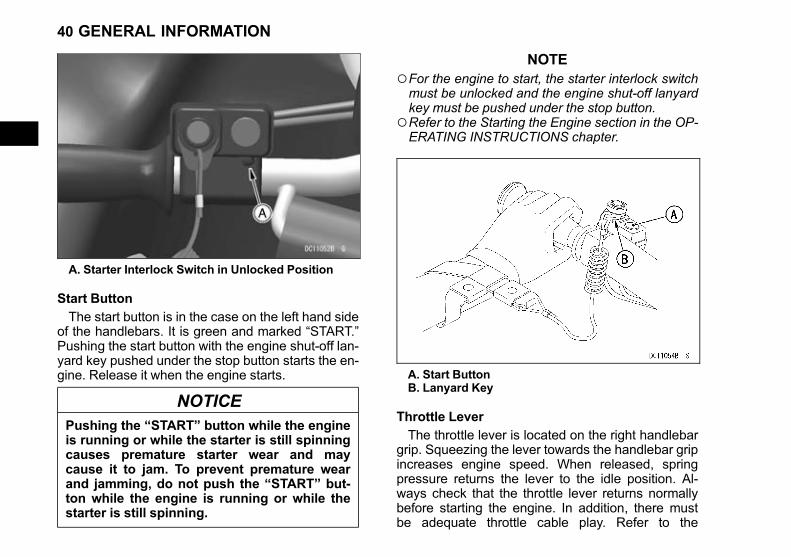
A. Starter Interlock Switch in Unlocked Position
Start Button
The start button is in the case on the left hand sideof the handlebars. It is green and marked “START.”Pushing the start button with the engine shut-off lan-yard key pushed under the stop button starts the en-gine. Release it when the engine starts.
NOTICEPushing the “START” button while the engineis running or while the starter is still spinningcauses premature starter wear and maycause it to jam. To prevent premature wearand jamming, do not push the “START” but-ton while the engine is running or while thestarter is still spinning.
NOTE○For the engine to start, the starter interlock switchmust be unlocked and the engine shut-off lanyardkey must be pushed under the stop button.
○Refer to the Starting the Engine section in the OP-ERATING INSTRUCTIONS chapter.
A. Start ButtonB. Lanyard Key
Throttle Lever
The throttle lever is located on the right handlebargrip. Squeezing the lever towards the handlebar gripincreases engine speed. When released, springpressure returns the lever to the idle position. Al-ways check that the throttle lever returns normallybefore starting the engine. In addition, there mustbe adequate throttle cable play. Refer to the
40 GENERAL INFORMATION
Black plate (41,1)
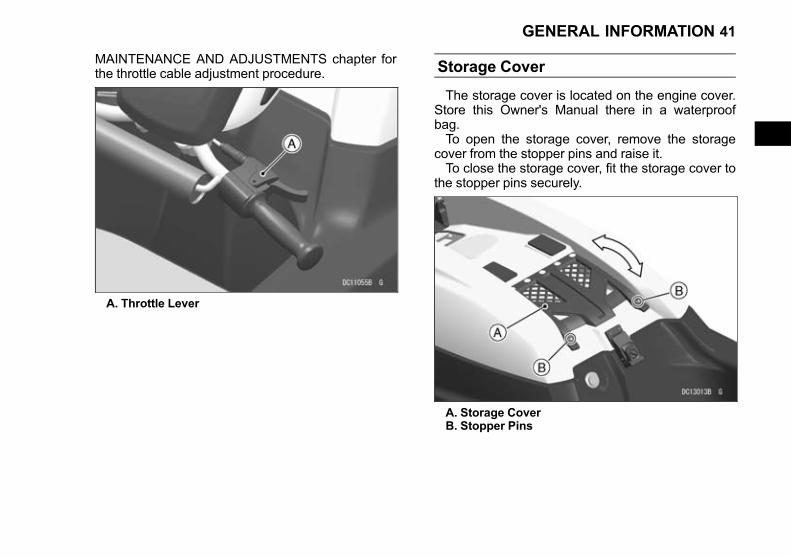
MAINTENANCE AND ADJUSTMENTS chapter forthe throttle cable adjustment procedure.
A. Throttle Lever
Storage Cover
The storage cover is located on the engine cover.Store this Owner's Manual there in a waterproofbag.To open the storage cover, remove the storage
cover from the stopper pins and raise it.To close the storage cover, fit the storage cover to
the stopper pins securely.
A. Storage CoverB. Stopper Pins
GENERAL INFORMATION 41
Black plate (42,1)
Engine Cover
The engine cover is held in place by a latch.
Removing the Engine Cover
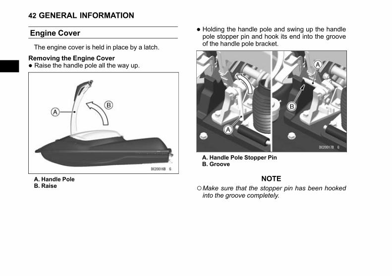
• Raise the handle pole all the way up.
A. Handle PoleB. Raise
• Holding the handle pole and swing up the handlepole stopper pin and hook its end into the grooveof the handle pole bracket.
A. Handle Pole Stopper PinB. Groove
NOTE○Make sure that the stopper pin has been hookedinto the groove completely.
42 GENERAL INFORMATION
Black plate (43,1)
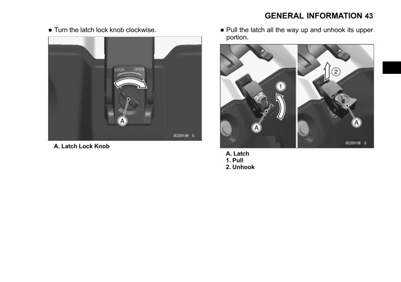
• Turn the latch lock knob clockwise.
A. Latch Lock Knob
• Pull the latch all the way up and unhook its upperportion.
A. Latch1. Pull2. Unhook
GENERAL INFORMATION 43

Black plate (44,1)
• Lift the rear of the engine cover.
• Remove the engine cover backward by holdingthe handgrip.
A. Engine CoverB. Handgrip1. Lift2. Backward
At the back of the engine cover, a fire extinguisherholder is provided.
A. Engine CoverB. Fire Extinguisher Holder
44 GENERAL INFORMATION
Black plate (45,1)
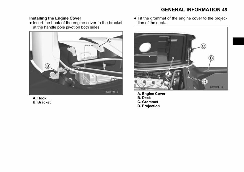
Installing the Engine Cover
• Insert the hook of the engine cover to the bracketat the handle pole pivot on both sides.
A. HookB. Bracket
• Fit the grommet of the engine cover to the projec-tion of the deck.
A. Engine CoverB. DeckC. GrommetD. Projection
GENERAL INFORMATION 45
Black plate (46,1)
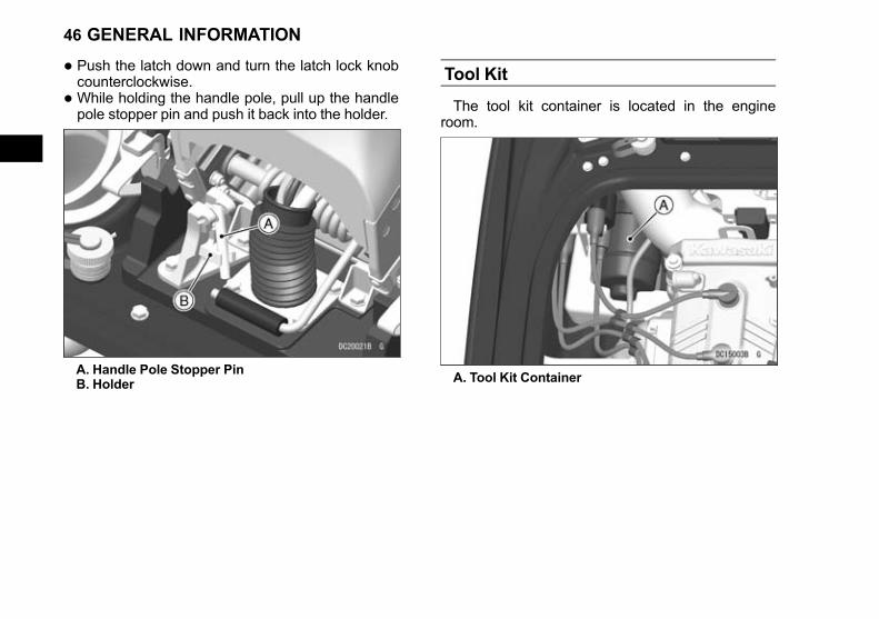
• Push the latch down and turn the latch lock knobcounterclockwise.
• While holding the handle pole, pull up the handlepole stopper pin and push it back into the holder.
A. Handle Pole Stopper PinB. Holder
Tool Kit
The tool kit container is located in the engineroom.
A. Tool Kit Container
46 GENERAL INFORMATION
Black plate (47,1)
Bilge Systems
This watercraft has a jet vacuum drainage systemat the rear end of the engine compartment. This sys-tem utilizes the water jet for propulsion to drain thebilge in the engine compartment. This system onlyworks when the engine is running on the water.
NOTICECheck the bilge system is working at regularintervals according to the Periodic Mainte-nance Chart. Refer to the MAINTENANCEAND ADJUSTMENTS chapter. Clear debrisfrom the pump intakes.
WARNINGDamage to the hull may cause a leak and thecapacity of the bilge pumping system is notdesigned to drain the hull in such instances.To avoid sinking the watercraft, immediatelyreturn to shore if the hull is damaged in anyway.
NOTE○To drain any water remaining in the bilge, removethe drain screws in the stern when the craft is outof the water.
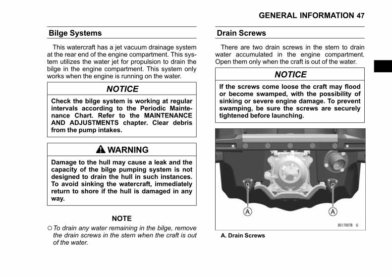
Drain Screws
There are two drain screws in the stern to drainwater accumulated in the engine compartment.Open them only when the craft is out of the water.
NOTICEIf the screws come loose the craft may floodor become swamped, with the possibility ofsinking or severe engine damage. To preventswamping, be sure the screws are securelytightened before launching.
A. Drain Screws
GENERAL INFORMATION 47
Black plate (48,1)
Loading/Accessories/Modifications
WARNINGIncorrect loading, overloading, use of acces-sories and/or modification of your watercraftmay affect its stability and handling and re-sult in an unsafe riding condition. Before youride the watercraft, make sure that it is notoverloaded and that you have followed theseinstructions.
Maximum load
75 kg (165 lb) including rider and luggage
• Ensure the total weight of rider and luggageaboard the watercraft does not exceed the maxi-mum load.
Important InformationAccessories: Kawasaki has no control over the
design or application of accessories. In some cases,improper installation or use of accessories, or water-craft modification, will void the warranty.Using non-genuine accessories or modifying your
watercraft may threaten your own safety and thesafety of others.
NOTE○Kawasaki Parts and Accessories have been spe-cially designed for use on Kawasaki watercraft.We strongly recommend that all parts and
accessories you add to your watercraft be genu-ine Kawasaki components.
Because a personal watercraft is sensitive tochanges in weight distribution, you must take ex-treme care in the fitting of additional accessories.The following general guidelines have been pre-pared to assist you in making your determinations.
• This watercraft is designed for the operator only -no passengers. Carrying a passenger can ad-versely affect the handling and stability which canlead to an accident. Also, do not carry animals onyour watercraft.
• Do not install accessories that impair the perform-ance of the watercraft.
48 GENERAL INFORMATION

Black plate (49,1)
Towing
Towing a personal watercraft
If your watercraft runs out of fuel or develops en-gine problems, tie a tow rope to the following loca-tion. Use a rope which is long enough to keep 6 m(20 ft) or more distance between towing and towedboats. Towing must be slow, not exceeding 8 km/h(5 mph). Be extra careful when towing; towing canaffect the steering of your watercraft and create ahazardous situation.
Being towed by a watercraft
• Attach the tow rope to the bow eye.
A. Bow Eye
• After towing, drain any water in the engine com-partment and check that no water enters the
engine following the procedure described in theAfter Submerging section in the OPERATING IN-STRUCTIONS chapter.
GENERAL INFORMATION 49
Black plate (50,1)
PRE-RIDE CHECK
Each day before using the watercraft, check thefollowing items:
WARNINGBE SURE TO PERFORM A PRE-RIDE CHECKeach day before using watercraft for safety.
Check Outside Craft□CLEAN PUMP - Clear the water intake, jet pump,and drive shaft of foreign objects.
□PUMP COVER TIGHT - Check the jet pump coverand intake grate for looseness. Tighten themounting bolts if necessary.
□HULL DAMAGE - Inspect the hull for damage.□DRAIN SCREWS - Check that the drain screws inthe stern are securely installed.
Check Inside Craft□STEERING - Check the operation of the steeringfor binding, rough spots, or excessive play. Adjustthe cable if needed (see Control Cables section inthe MAINTENANCE AND ADJUSTMENTS chap-ter). The steering cable is sealed at both ends anddoes not need lubrication. If the seals are dam-aged, the cable must be replaced. Turn the han-dlebars and make sure the steering nozzle movesin response to the turn.
□THROTTLE CONTROL - Check the operation ofthe throttle for binding, rough spots or excessive
play. Adjust the cable if needed (see Control Ca-bles section in the MAINTENANCE AND AD-JUSTMENTS chapter). The throttle lever mustreturn to the fully closed position when released.
WARNINGA stuck throttle can cause loss of control andan accident resulting in injury or death. If thethrottle does not return freely and completely,do not ride and have it inspected by your Ka-wasaki dealer.
□VENTILATE ENGINE COMPARTMENT - Removethe engine cover and keep open for several mi-nutes to purge gasoline fumes from the enginecompartment.
WARNINGA concentration of gasoline fumes in the en-gine compartment can cause a fire or explo-sion. To prevent a fire or explosion, removethe engine cover to vent the engine compart-ment.
□BATTERY TERMINALS - Check the battery termi-nal screws for tightness, and make sure terminalcovers are in place.
50 PRE-RIDE CHECK
Black plate (51,1)
WARNINGLoose battery cables can create sparks whichcan cause a fire or explosion resulting in in-jury or death. Make sure the battery terminalscrews are tightened securely and the coversare installed over the terminals.
□FIRE EXTINGUISHER - Check the fire extin-guisher is fully charged.
□FUEL PRESSURE - Loosen the fuel filler cap torelieve any pressure, then tighten the cap se-curely.
□FUEL LEVEL - Turn the watercraft upright andcheck the fuel level. Refill if necessary.
□ENGINE OIL LEVEL - Check the oil level in theengine. Refill if necessary. Refer to the Engine Oilsection in the MAINTENANCE AND ADJUST-MENTS chapter.
□FUEL LEAKS - Check the engine compartmentfor fuel leaks.
□OIL LEAKS - Check the engine compartment foroil leaks.
□FASTENERS - Check and tighten any loose bolts,nuts, or clamps.
□HOSE CONNECTIONS - Be sure all hose con-nections are secure and that all hose clamps aretight. Check all hoses for cracks or deteriorationand replace if necessary.
□DRAIN BILGE - Drain any water out of the enginecompartment by removing the drain screws.
Install the drain screws securely when all thewater has been drained.
□ENGINE SHUT-OFF LANYARD KEY - Start theengine and run it for a few seconds (see Startingthe Engine section in the OPERATING INSTRUC-TIONS chapter). Pull the lanyard key off the stopbutton to check that the engine stops immediately.
DANGERExhaust gas contains carbon monoxide, acolorless, odorless poisonous gas. Inhalingcarbon monoxide can cause serious brain in-jury or death. DO NOT run the engine in en-closed areas. Operate only in a well-ventilated area.
NOTICETo prevent overheating resulting in engineand exhaust system damage, do not run theengine with the watercraft out of the water formore than 15 seconds at a time.Never operate the engine at maximum speedout of the water.
□STOP BUTTON - Again start the engine, run it fora few seconds, and then check that the engine“STOP” button works.
□ENGINE COVER - Install the engine cover, andcheck that the engine cover latch is secure.
□RIDER PROTECTION - Always wear the properflotation device and protective gear.
PRE-RIDE CHECK 51

Black plate (52,1)
OPERATING INSTRUCTIONS
Basic Knowledge for Operation
Read “SAFETY INFORMATION” and “PREVENTMAJOR DAMAGE” without fail. Please be sure toconduct the PRE-RIDE CHECK before boarding.
Operation by unskilled riders
• On your first ride, familiarize yourself with the han-dling of the craft. Vary the engine speed with thethrottle lever to get the feel of throttle influence onsteering.
Operator Swimming Ability
• Riders of personal watercraft can fall into thewater and experience exposure. Operator mustbe a competent swimmer and never travel fartherfrom shore than they can swim.
Maximum Number of Person
This watercraft is designed to carry only the oper-ator. Never exceed the maximum load limit 75 kg(165 lb) (see Loading/Accessories/Modificationssection in the GENERAL INFORMATION chapter).
WARNINGOverloading this watercraft can adversely af-fect handling and stability which can lead toan accident. To reduce the risk of having anaccident, do not exceed the maximum recom-mended number of people.The total weight including luggage mustnever exceed the load capacity limit.
Safe Riding Rules
• Always follow these rules when operating yourwatercraft, for your own safety and that of others.
• Always comply with any Navigation Rules in effectin your area. The Coast Guard office or state boat-ing authority nearest you can usually furnish youwith the applicable rules. Check local and stateregulations before operating. Kawasaki recom-mends that all operators complete an approvedboating safety course.
Personal Flotation Device and Safety Gear
U.S. federal regulations require that one U.S.Coast Guard approved personal flotation device(PFD) be carried when operating on the water underCoast Guard jurisdiction. In some state waters notunder federal jurisdiction, other flotation devices arepermissible in addition to those specified by federallaw. Other countries may have their own standards
52 OPERATING INSTRUCTIONS

Black plate (53,1)
and regulations; be sure to follow them. As a rule,waist-type ski belts do not qualify as adequate flota-tion devices. The full vest type is recommended.Check local regulations to see what type of personalflotation device may be required in your area.Drowning Hazard: a personal flotation device
(PFD) must be worn by the operator. Kawasaki rec-ommends that the operator wear a vest-type PFD(type 1, 2 or 3) at all times.
WARNING
• All riders must wear a Coast Guard approved personalflotation device (PFD) that is suitable for personalwatercraft (PWC) use. Kawasaki recommends a vest-type PFD. Hard impact with the water can result in un-consciousness and/or drowning. Make sure that yourPFD fits correctly and tightly so that it does not comeoff in the water. Never use an adult size PFD for chil-dren.
• Severe internal injuries can occur if water is forced intobody cavities as a result of falling into water or beingnear the jet thrust nozzle. Normal swimwear does notadequately protect against forceful water entry into therectum or vagina. All riders must wear a wet suit bot-tom or clothing that provides equivalent protection.Wet suits are made of a thick material (neoprene) thatsignificantly retards the velocity of water passingthrough it. Normal swimwear will not adequately pro-tect you but some other aquatic wear may protectagainst this injury. Swimsuits that may be displaced bythe force of the water will not provide that protection.Materials that are thicker, materials that are a tighterweave, materials that are water repellant, and materialsthat are closer fitting will tend to provide more protec-tion. In the absence of wearing a wet suit bottom, youshould select a clothing design that will maximize yourprotection.
• Wear protective footwear, gloves and goggles(glasses).
OPERATING INSTRUCTIONS 53

Black plate (54,1)
Watercraft Helmet..... Something You ShouldKnow
A helmet helps protect your head, but could con-tribute to neck injuries.Before wearing a helmet on a personal watercraft
you must weigh the benefits and risks.Benefits: Helmets offer some head protection
from impacts with hard objects.Risks: Helmets could reduce peripheral vision
and increase fatigue; both of which could lead to acollision. Helmets could also increase loads on theneck and throat if you fall into the water, which couldresult in severe injuries.
You must decide.If you plan to ride under conditions in which you
believe there is a higher chance that your head maybe hit by a hard object, such as falling during a race,you may choose to wear a helmet and accept therisks. On the other hand, if head impact with thewater is more likely, you may choose to not wear ahelmet.
Fire Extinguisher
A charged and functional fire extinguisher must becarried on board, and may be stored in the holder ofthe engine cover (see Engine Cover section in theGENERAL INFORMATION chapter). Be sure to in-stall the fire extinguisher securely.
Because the watercraft is an inboard boat lessthan 4.8 m (16 ft) in length, federal regulations re-quire that a fire extinguisher rated “B-1” (minimum 1kg or 2 pound capacity) be aboard when operatingon navigable waters under Coast Guard Jurisdic-tion. In addition, most states, parks, and wildlife de-partments require that a U.S.C.G. approved fireextinguisher be carried aboard, even on waters notunder federal jurisdiction.Other countries may have their own standards
and regulations; be sure to follow them.
WARNINGA fire aboard the watercraft may cause burns,melt the hull and cause it to sink, leaving theoperator stranded. To prevent any fire fromconsuming the watercraft, always carry a fireextinguisher.
54 OPERATING INSTRUCTIONS

Black plate (55,1)
Standard equipment does not include a fire extin-guisher. Many owners prefer to provide their ownfire extinguishers. If you wish, your dealer can fur-nish you with an approved Kawasaki accessory fireextinguisher (P/N. W99997-101A).
Weather condition
• Before operating your watercraft, check with localweather reports.
NOTE○Generally, weather can change more suddenlyover the sea than over the land, so pay close at-tention to the weather when using the watercraft.If you notice any signs of strong wind or fog, im-mediately return to shore.
WARNING
• Do not operate the watercraft in adverseweather condition or in wild waves. It couldlead marine peril.
• Slow down before crossing waves. Cross-ing wild waves at high speeds could in-crease the risk of back/spinal injury(paralysis), facial injuries, and broken legs,ankles, and other bones.
• The operator must judge what is a safe speed tak-ing into consideration visibility, traffic, weatherconditions, waves, etc. Water conditions such asconverging waves can have considerable influ-ence on the ride characteristics of a personalwatercraft and can cause the operator to fall off.Additionally, attempting to achieve maximumspeed in adverse conditions can cause abrupt
OPERATING INSTRUCTIONS 55

Black plate (56,1)
movement of the boat causing possible injury tothe riders. Basic Operating and Riding
Posture on the Riding Platform
When riding the watercraft, stand on the ridingplatform.
WARNINGRough water can cause the watercraft to sud-denly rise, creating the potential for the han-dlebars to strike and injure a rider who ispositioned too close. To avoid injury, neverride with any part of your body immediatelyabove the handlebars.
If porpoising occurs, that is, the front of the craftrises and falls rapidly, move your body weight fur-ther forward.
Standing Up
• Maintaining a steady speed, raise the handlebarsslightly and place one foot near the front of the rid-ing platform.
• Balance yourself and slowly rise to a standing po-sition, bringing the handlebars up with you as yourise.
56 OPERATING INSTRUCTIONS
Black plate (57,1)
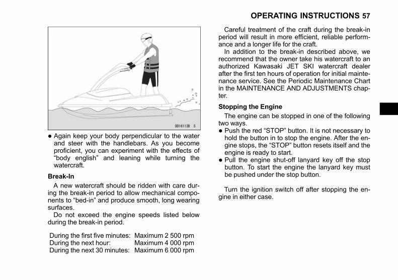
• Again keep your body perpendicular to the waterand steer with the handlebars. As you becomeproficient, you can experiment with the effects of“body english” and leaning while turning thewatercraft.
Break-In
A new watercraft should be ridden with care dur-ing the break-in period to allow mechanical compo-nents to “bed-in” and produce smooth, long wearingsurfaces.Do not exceed the engine speeds listed below
during the break-in period.
During the first five minutes:During the next hour:During the next 30 minutes:
Maximum 2 500 rpmMaximum 4 000 rpmMaximum 6 000 rpm
Careful treatment of the craft during the break-inperiod will result in more efficient, reliable perform-ance and a longer life for the craft.In addition to the break-in described above, we
recommend that the owner take his watercraft to anauthorized Kawasaki JET SKI watercraft dealerafter the first ten hours of operation for initial mainte-nance service. See the Periodic Maintenance Chartin the MAINTENANCE AND ADJUSTMENTS chap-ter.
Stopping the Engine
The engine can be stopped in one of the followingtwo ways.
• Push the red “STOP” button. It is not necessary tohold the button in to stop the engine. After the en-gine stops, the “STOP” button resets itself and theengine is ready to start.
• Pull the engine shut-off lanyard key off the stopbutton. To start the engine the lanyard key mustbe pushed under the stop button.
Turn the ignition switch off after stopping the en-gine in either case.
OPERATING INSTRUCTIONS 57

Black plate (58,1)
WARNINGA JET SKI watercraft requires throttle (thrust)to steer and help you to avoid objects - youhave no directional control when the engineis stopped. To avoid objects the engine mustbe running and throttle applied to steer awayfrom objects. Always check the throttle andsteering controls for proper operation beforestarting the watercraft.
A. Stop ButtonB. Lanyard Key
If the engine must be stopped immediately in anemergency, push the red “STOP” button or pull theengine shut-off lanyard key off the stop button.Some possible “EMERGENCY” situations are:
• The engine speeds out of control.
• The throttle lever does not release completely.
WARNINGA JET SKI watercraft requires throttle (thrust)to steer and help you to avoid objects - youhave no directional control when the engineis stopped. If the throttle fails, do not operatethe watercraft until the source of the problemis found and corrected.
WARNINGAfter riding, remove the engine shut-off lan-yard key from watercraft to avoid unauthor-ized use by children or others.
NOTICEA discharged battery will not provide powerto start the engine. To prevent the batteryfrom discharging, always turn the ignitionswitch “OFF” after stopping the engine.
Starting the Engine
• Read the PRE-RIDE CHECK chapter in this man-ual and follow its instructions before putting thewatercraft in the water.
58 OPERATING INSTRUCTIONS
Black plate (59,1)
• After transporting or refueling and before startingthe engine, remove the engine cover and keepopen for several minutes to ventilate the enginecompartment.
WARNINGA concentration of gasoline fumes in the en-gine compartment can cause a fire or explo-sion. To prevent a fire or explosion, removethe engine cover to vent the engine compart-ment.
• Place the watercraft in at least 0.8 m (2.6 ft) ofwater which is clear of weeds and debris. Makesure the area ahead of the watercraft is clear ofswimmers, boats, and obstacles.
NOTICE
• When starting the engine or riding, thewatercraft must be in water at least 0.8 m(2.6 ft) deep. Sand or debris from the bot-tom may be drawn into the jet pump anddamage the pump and impeller, and possi-bly clog cooling lines.
• If operating in shallow or debris-ladenwater, objects or sand from the bottom canget sucked in damaging the impeller andpossibly clogging cooling hoses which cancause severe engine damage from over-heating.
• Avoid beaching the watercraft. Stones andsand can scratch the hull and be drawn intothe jet pump, causing damage to the impel-ler.
• Move to the rear of the watercraft and stand onthe riding platform.
• Push the lanyard key under the stop button andput your left hand through the other end of the lan-yard to attach it to your wrist. Pull the lanyard tomake sure it is securely attached and keep it freefrom the handlebars so that the engine stops if thedriver falls off.
NOTE○The engine does not start with the lanyard key re-moved from the stop button.
OPERATING INSTRUCTIONS 59

Black plate (60,1)
• Attach the ignition key to the switch with the arrowupward and while pushing the key turn it to the“ON” position. Be sure to remove the key immedi-ately and store it in the storage cover.
A. Ignition KeyB. Arrow
NOTICEAfter turning the ignition switch “ON,” re-move the key. Stow it in a secure place on thewatercraft or with you while riding.
NOTE○The watercraft is equipped with a vehicle-downsensor which causes the engine to stop automati-cally if the watercraft has capsized. After righting
the watercraft, first turn the ignition key to “OFF”and then back to “ON” and push the start buttonto start the engine.
• Check that the starter interlock switch is posi-tioned to the right.
• Scan for people, objects, and other watercraft.
• With your left hand, push the green start buttonand release it when the engine starts. If the en-gine does not start within 5 seconds, release thebutton. Wait 15 seconds before trying again. If theengine does not start after several attempts, seethe IN AN EMERGENCY chapter.
A. Start ButtonB. Lanyard Key
60 OPERATING INSTRUCTIONS

Black plate (61,1)
NOTE○Wait 15 seconds between each operation of thestarter. This will extend battery and starter life sig-nificantly.
NOTICEDo not push the “START” button while the en-gine is running or while the starter is stillspinning as this causes premature starterwear and may cause it to jam.
• After the engine has started, allow it to warm upfor about 1 minute. Apply a little throttle occasion-ally. Excessive idling can foul the spark plugs.
• Check that water comes out of the bypass outletin the right side of the hull when the throttle is ap-plied. This indicates that cooling water is circulat-ing. If there is none, shut off the engine and findthe source of the problem. When the exhaust sys-tem is dry, it can take up to 15 seconds for waterto appear at the bypass outlet.
A. Bypass Outlet
OPERATING INSTRUCTIONS 61

Black plate (62,1)
Launching
Launching/Start
Launching• Before putting the watercraft in the water, be sureyou have followed the Pre-ride Checklist.
• Before launching, check the ramp for suitable sur-face conditions, inclination and width for both thetrailer and tow vehicle.
NOTICEEnsure the drain screws are securely tight-ened before launching to prevent floodingwhich may cause sinking or severe enginedamage.
• Attach a bow line to the watercraft and detach thetrailer tie-downs.
• Wait until it's your turn then back the trailer to thewater.
• Unlock the winch and push the craft slowly off thetrailer into the water.
• Move your watercraft to a docking or loading areaand park your tow vehicle. Do not block the ramp.
Deep Water StartDeep water starting is the primary means of start-
ing the watercraft. It is not necessarily the easiestway to start, but it must be mastered so that you canget going again after the inevitable spill in deepwater.
WARNINGAvoid forceful jet thrust and limited visibilitywhile reboarding. Get to a standing or kneel-ing position quickly, but do not expose your-self to forceful jet thrust.
• Move to the rear of the watercraft.
• Assume a prone position behind the watercraftwith your hands grasping the handlebars and yourforearms resting on the tail fins.
• Pull your body up onto the riding platform and on-to your knees, using your elbows on the fins forleverage.
62 OPERATING INSTRUCTIONS

Black plate (63,1)
• Scan for people, objects, and other watercraft.
• Start the engine.
• Apply the throttle to produce enough thrust fromthe jet pump to allow directional control over thewatercraft.
• Accelerate gradually as you proceed into openwater. Remember to observe “No Wake” zonesand speed limits.
• As speed increases the watercraft will level out inthe water. This is called planing.
• Once the watercraft is planing, you can back offthe throttle and select your desired speed.
• Keep alert for other watercrafts, swimmers, or ob-structions in your path.
Shallow Water StartThis is the easiest way to launch a watercraft, but
it shouldn’t be relied upon merely because it’s easy.
The deep water start is still the most importantlaunch to a beginner.Whenever possible, anchor the watercraft in shal-
low water instead of beaching it. This will reducescratches to the hull and prevent sand and rocksfrom entering into the jet pump causing damage tothe pump when restarting the engine.If the watercraft is beached, sand and rocks which
are pushed into the jet pump by natural wave actioncan be flushed out by pushing down on the sternvigorously many times.
NOTICE
• When starting the engine or riding, thewatercraft must be in water at least 0.8 m(2.6 ft) deep. Sand or debris from the bot-tom may be drawn into the jet pump anddamage the pump and impeller, and possi-bly clog cooling lines.
• If operating in shallow or debris-ladenwater, objects or sand from the bottom canget sucked in damaging the impeller andpossibly clogging cooling hoses which cancause severe engine damage from over-heating.
• Move to the rear of the watercraft.
• Grasp both handlebar grips and put one knee uponto the riding platform, balancing on your otherfoot.
OPERATING INSTRUCTIONS 63

Black plate (64,1)
• Check that the water ahead of you is clear andpoint the handlebars straight ahead.
• Start the engine.
• Apply the throttle to produce enough thrust fromthe jet pump to allow directional control over thewatercraft.
• Keep alert for other watercrafts, swimmers, or ob-structions in your path.
• As the watercraft accelerates, pull your other kneeup onto the riding platform and move as far for-ward as possible, without interfering with handle-bars movement. Keep your body perpendicular tothe water with your weight forward and low.
Standing StartThis method can be used by the more experi-
enced watercraft rider.
• Start the engine in at least 0.8 m (2.6 ft) of water.
• Put one foot in the riding platform, balancing your-self with the other foot on the beach bottom.
64 OPERATING INSTRUCTIONS

Black plate (65,1)
• Accelerate to planing speed, and place your otherfoot on the rear section of the riding platform.
• Keep alert for other watercrafts, swimmers, or ob-structions in your path.
Stopping the JET SKI Watercraft
The watercraft depends on forward motion tokeep it planing (level), so the rear of the boat willusually submerge on stopping, depending on riderweight. Be prepared to get off the boat when itstops.
WARNINGThis high-performance watercraft is capableof high speeds that can be hazardous whendirectly approaching any moving or station-ary object. To avoid an accident, never di-rectly approach any moving or stationaryobject closer than 100 meters (328 feet) whentraveling at high speed. Always throttle downbefore approaching your intended stoppingarea.
OPERATING INSTRUCTIONS 65

Black plate (66,1)
This watercraft stops by using natural water dragto bring the craft to a halt.
• Release the throttle before you reach your in-tended stopping area.
• Coast towards the stopping area with the engineidling.
NOTICEAvoid beaching the watercraft. Stones andsand can scratch the hull and be drawn intothe jet pump, causing damage to the impeller.
A. Throttle Lever
• Press the stop button or pull the lanyard key offthe stop button to stop the engine.
A. Stop ButtonB. Lanyard Key
Releasing the throttle slows forward motion butthe engine will still be running, so you can steer theboat after reapplying the throttle. In this manner youcan turn and move away from any obstacles.Push the stop button when you are approaching
the shore and intend to stop. The engine stops im-mediately, so it prevents sand or debris from enter-ing and damaging the jet pump. Never run theengine in water less than 0.8 m (2.6 ft) deep.
Stopping SkillsStopping distance depends partially on rider
weight and position, idle set speed, and operatingspeed. Experienced operators can usually shortenstopping distance by using various riding techni-ques. Turning the boat sharply (using the throttle)
66 OPERATING INSTRUCTIONS
Black plate (67,1)
while stopping is a method which can be used to de-crease stopping distance.
Minimum Stopping DistancesThe minimum stopping distance of this watercraft
with the operator from maximum speed is 75 m (246ft). (Obtained under controlled conditions, actualstopping distances may vary depending on vehicleload and water conditions.)
Turning the JET SKI Watercraft
Turning the watercraft requires a combination ofthree actions:
• Turning the handlebars
• Leaning into the turn
• Using the throttle
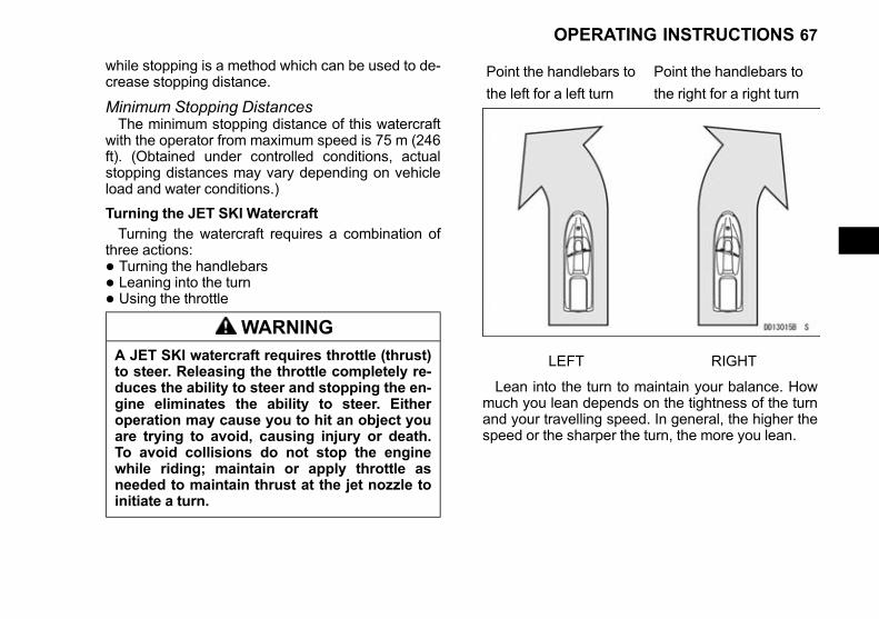
WARNINGA JET SKI watercraft requires throttle (thrust)to steer. Releasing the throttle completely re-duces the ability to steer and stopping the en-gine eliminates the ability to steer. Eitheroperation may cause you to hit an object youare trying to avoid, causing injury or death.To avoid collisions do not stop the enginewhile riding; maintain or apply throttle asneeded to maintain thrust at the jet nozzle toinitiate a turn.
Point the handlebars to Point the handlebars to
the left for a left turn the right for a right turn
LEFT RIGHT
Lean into the turn to maintain your balance. Howmuch you lean depends on the tightness of the turnand your travelling speed. In general, the higher thespeed or the sharper the turn, the more you lean.
OPERATING INSTRUCTIONS 67
Black plate (68,1)
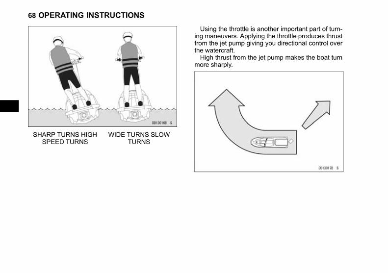
SHARP TURNS HIGHSPEED TURNS
WIDE TURNS SLOWTURNS
Using the throttle is another important part of turn-ing maneuvers. Applying the throttle produces thrustfrom the jet pump giving you directional control overthe watercraft.High thrust from the jet pump makes the boat turn
more sharply.
68 OPERATING INSTRUCTIONS

Black plate (69,1)
Less thrust from the jet pump makes the boat turnless sharply.
If you release the throttle completely, there is littlethrust from the jet pump. The boat turns slowly andsteering ability is reduced.
IDLE = SLOW, GRADUALTURN
OPERATING INSTRUCTIONS 69

Black plate (70,1)
If you stop the engine while riding, there is nothrust from the jet pump. The boat will go straightahead even though the handlebars is turned.
NO THRUST = NO TURN
This is one characteristic of jet drive boats whichis important to remember when you make an emer-gency maneuver: YOU MUST HAVE THRUST TOTURN, so keep the throttle on or apply throttle asneeded to maintain thrust at the jet nozzle.
• Throttle down before entering a turn.Before making a turn, always look over your
shoulder to make sure no other watercraft is comingfrom behind.
Docking the JET SKI Watercraft
• When docking, use the throttle efficiently both tocontrol the craft's speed and to keep directionalcontrol over the craft.
• When you are approaching the shore where youintend to land, push the stop button to preventsand from entering the jet pump and the impeller.Do not operate the engine in water shallower than0.8 m (2.6 ft).
NOTICE
• When starting the engine or riding, thewatercraft must be in water at least 0.8 m(2.6 ft) deep. Sand or debris from the bot-tom may be drawn into the jet pump anddamage the pump and impeller, and possi-bly clog cooling lines.
• If operating in shallow or debris-ladenwater, objects or sand from the bottom canget sucked in damaging the impeller andpossibly clogging cooling hoses which cancause severe engine damage from over-heating.
• Avoid beaching the watercraft. Stones andsand can scratch the hull and be drawn intothe jet pump, causing damage to the impel-ler.
• Remember that stopping the engine causes youto lose steering control, so cut the engine onlyafter you have reduced speed and maneuveredinto your final approaching position. You cannot
70 OPERATING INSTRUCTIONS

Black plate (71,1)
make any emergency maneuvers with the enginestopped.
Fall Recovery
If the operator falls off the craft, the lanyard key ispulled off the stop button and the engine is stoppedimmediately.
WARNINGMaintaining hold of the handlebars during afall may cause you strike the watercraft, re-sulting in injury. To avoid injury during a fall,release your grip on the handlebars.
NOTICEHanging onto the handlebars during a fall cancause misalignment of the handle pole whichcan cause damage to the handle pole and en-gine cover.
• Reboard from the rear of the craft. Push the lan-yard key under the stop button, and push the startbutton to start the engine.
Righting the Capsized Watercraft
If the watercraft should capsize, the engine isstopped by the lanyard key being pulled off the stopbutton by the operator. Use the following procedureimmediately to right the craft.
WARNINGThis watercraft will not self-right if capsized,leaving the operator stranded. To avoid beingstranded in the case of capsizing, be sure youknow the proper righting procedure.
• Make sure the engine is stopped. If it is notstopped, immediately pull the lanyard key off thestop button or push the stop button to stop the en-gine.
NOTICETo prevent severe engine damage, immedi-ately stop the engine if the craft capsizes. If itcontinues running whilst capsized, water canenter the throttle body and engine, lockingthe engine and causing severe and immediatedamage to internal engine parts.Do not operate the watercraft with water inthe engine.Do not try to start the engine until it is com-pletely empty of water; internal engine partscould be severely and immediately damaged.If water gets into the engine, follow the proce-dure described in the After Submerging sec-tion.
• Swim to the rear corner of the capsized craft.
• Push down on the port side of the craft with onehand and reach across the hull and grasp the rear
OPERATING INSTRUCTIONS 71
Black plate (72,1)
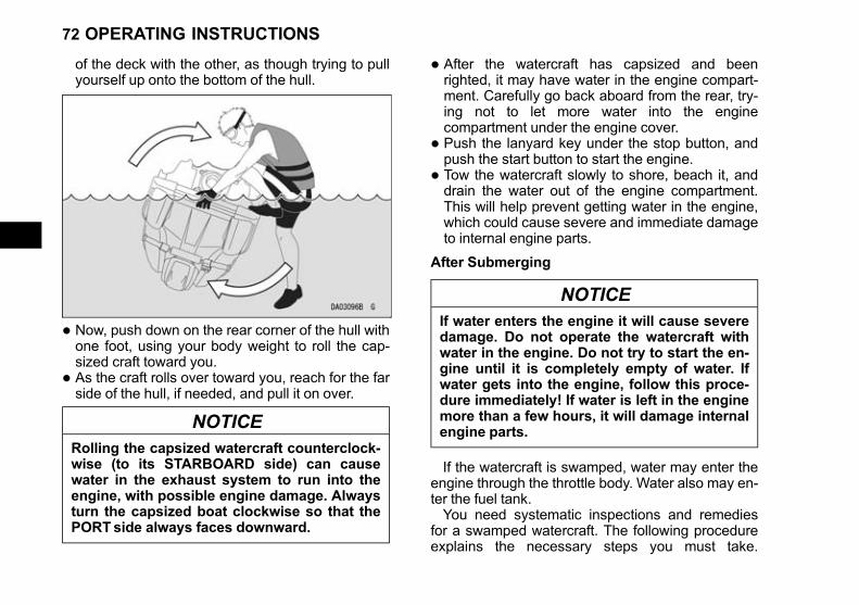
of the deck with the other, as though trying to pullyourself up onto the bottom of the hull.
• Now, push down on the rear corner of the hull withone foot, using your body weight to roll the cap-sized craft toward you.
• As the craft rolls over toward you, reach for the farside of the hull, if needed, and pull it on over.
NOTICERolling the capsized watercraft counterclock-wise (to its STARBOARD side) can causewater in the exhaust system to run into theengine, with possible engine damage. Alwaysturn the capsized boat clockwise so that thePORTside always faces downward.
• After the watercraft has capsized and beenrighted, it may have water in the engine compart-ment. Carefully go back aboard from the rear, try-ing not to let more water into the enginecompartment under the engine cover.
• Push the lanyard key under the stop button, andpush the start button to start the engine.
• Tow the watercraft slowly to shore, beach it, anddrain the water out of the engine compartment.This will help prevent getting water in the engine,which could cause severe and immediate damageto internal engine parts.
After Submerging
NOTICEIf water enters the engine it will cause severedamage. Do not operate the watercraft withwater in the engine. Do not try to start the en-gine until it is completely empty of water. Ifwater gets into the engine, follow this proce-dure immediately! If water is left in the enginemore than a few hours, it will damage internalengine parts.
If the watercraft is swamped, water may enter theengine through the throttle body. Water also may en-ter the fuel tank.You need systematic inspections and remedies
for a swamped watercraft. The following procedureexplains the necessary steps you must take.
72 OPERATING INSTRUCTIONS
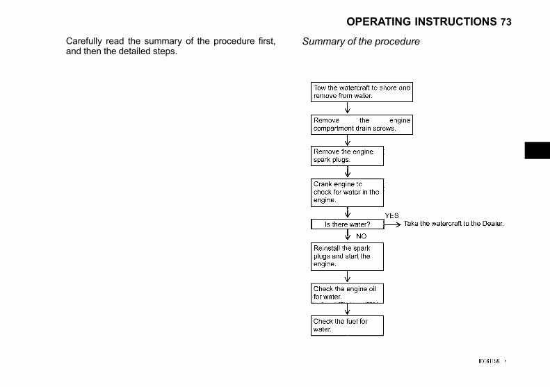
Black plate (73,1)
Carefully read the summary of the procedure first,and then the detailed steps.
Summary of the procedure
OPERATING INSTRUCTIONS 73
Black plate (74,1)
Details of the steps1. Remove the craft from the water, and remove the
engine cover.2. Remove the drain screws in the stern to drain
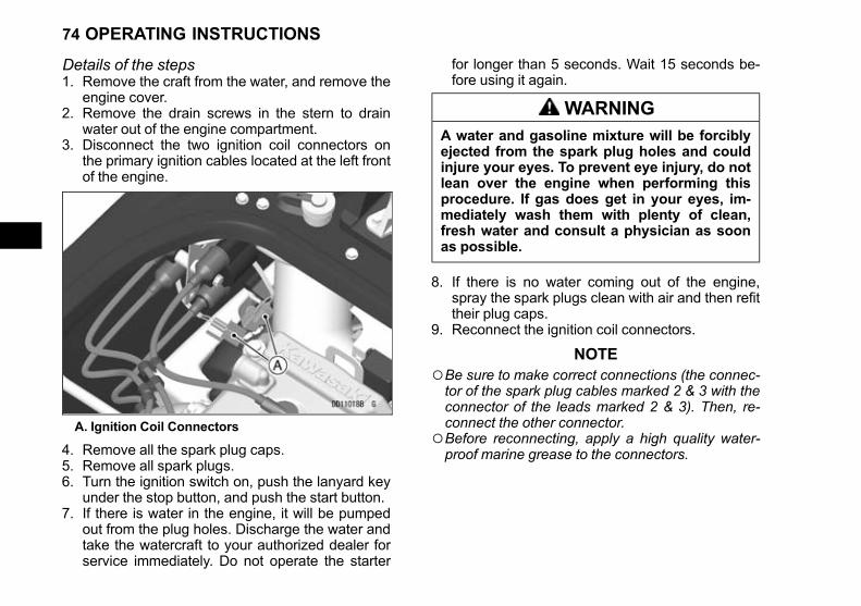
water out of the engine compartment.3. Disconnect the two ignition coil connectors on
the primary ignition cables located at the left frontof the engine.
A. Ignition Coil Connectors
4. Remove all the spark plug caps.5. Remove all spark plugs.6. Turn the ignition switch on, push the lanyard key
under the stop button, and push the start button.7. If there is water in the engine, it will be pumped
out from the plug holes. Discharge the water andtake the watercraft to your authorized dealer forservice immediately. Do not operate the starter
for longer than 5 seconds. Wait 15 seconds be-fore using it again.
WARNINGA water and gasoline mixture will be forciblyejected from the spark plug holes and couldinjure your eyes. To prevent eye injury, do notlean over the engine when performing thisprocedure. If gas does get in your eyes, im-mediately wash them with plenty of clean,fresh water and consult a physician as soonas possible.
8. If there is no water coming out of the engine,spray the spark plugs clean with air and then refittheir plug caps.
9. Reconnect the ignition coil connectors.
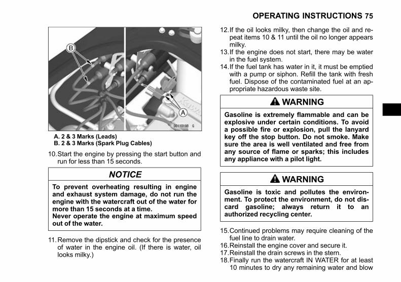
NOTE○Be sure to make correct connections (the connec-tor of the spark plug cables marked 2 & 3 with theconnector of the leads marked 2 & 3). Then, re-connect the other connector.
○Before reconnecting, apply a high quality water-proof marine grease to the connectors.
74 OPERATING INSTRUCTIONS
Black plate (75,1)
A. 2 & 3 Marks (Leads)B. 2 & 3 Marks (Spark Plug Cables)
10.Start the engine by pressing the start button andrun for less than 15 seconds.
NOTICETo prevent overheating resulting in engineand exhaust system damage, do not run theengine with the watercraft out of the water formore than 15 seconds at a time.Never operate the engine at maximum speedout of the water.
11.Remove the dipstick and check for the presenceof water in the engine oil. (If there is water, oillooks milky.)
12.If the oil looks milky, then change the oil and re-peat items 10 & 11 until the oil no longer appearsmilky.
13.If the engine does not start, there may be waterin the fuel system.
14.If the fuel tank has water in it, it must be emptiedwith a pump or siphon. Refill the tank with freshfuel. Dispose of the contaminated fuel at an ap-propriate hazardous waste site.
WARNINGGasoline is extremely flammable and can beexplosive under certain conditions. To avoida possible fire or explosion, pull the lanyardkey off the stop button. Do not smoke. Makesure the area is well ventilated and free fromany source of flame or sparks; this includesany appliance with a pilot light.
WARNINGGasoline is toxic and pollutes the environ-ment. To protect the environment, do not dis-card gasoline; always return it to anauthorized recycling center.
15.Continued problems may require cleaning of thefuel line to drain water.
16.Reinstall the engine cover and secure it.17.Reinstall the drain screws in the stern.18.Finally run the watercraft IN WATER for at least
10 minutes to dry any remaining water and blow
OPERATING INSTRUCTIONS 75

Black plate (76,1)
any foreign matter (like salt) out through the ex-haust.
NOTE○If this procedure seems difficult and beyond yourmechanical abilities, see your authorized Kawa-saki dealer.
End of the Day Checklist
NOTICESince JET SKI personal watercraft are not de-signed to be docked in the water for extendedperiods, prolonged immersion in water willcause the hull paint to bubble and peel, aswell as electrolytic erosion of some metalparts in the jet pump. To prevent this, removeyour JET SKI watercraft from the water at theend of each day's use; do not leave it in thewater overnight. Your JET SKI watercraft willlast longer and look better.
Drain the Exhaust System
To prevent major engine damage, you must per-form the following procedure to expel excess waterfrom the exhaust system. This helps prevent prema-ture wear due to internal engine corrosion and thebuild up of salt or other mineral deposits that canlead to cooling system blockage and overheating.
• After each use in fresh water, remove the water-craft from the water.
• Start the engine and run it for several seconds topurge the exhaust system of excess water. Revthe engine repeatedly, until water stops comingout of the exhaust at the stern.
76 OPERATING INSTRUCTIONS

Black plate (77,1)
NOTICETo prevent overheating resulting in engineand exhaust system damage, do not run theengine with the watercraft out of the water formore than 15 seconds at a time.Never operate the engine at maximum speedout of the water.
• After each use in salt water, flush the cooling sys-tem with fresh water (see Cooling System Flush-ing section in the MAINTENANCE ANDADJUSTMENTS chapter). This will help preventbuild up of salt deposits and eventual cooling sys-tem blockage.
Clean the Engine Compartment
• Remove the engine cover.
• If water has accumulated in the engine compart-ment, remove the drain screws in the stern todrain water out of the compartment.
• When the watercraft has been used at sea, rinsethe engine compartment with fresh water.
NOTICEWater can enter the engine through the airbox and cause severe engine damage, andshorts in electrical equipment. To preventwater damage, cover the air intake hole anddo not spray electrical equipment.
A. Drain Screws
• Be sure to reinstall the drain screws after draining.
• If you won't be using the watercraft for more thana week, lubricate the internal engine componentsto help prevent corrosion.
• If you won't be using the watercraft for more thantwo weeks, remove the battery and keep fullycharged using a maintenance charger (see Bat-tery section in the MAINTENANCE AND AD-JUSTMENTS chapter).
• Wipe the engine compartment dry, and install theengine cover.
• When the watercraft is ready for storage, installthe engine cover loosely, and block it with 10 mm(one half inch) spacers to aid air circulation andprevent condensation from forming.
OPERATING INSTRUCTIONS 77
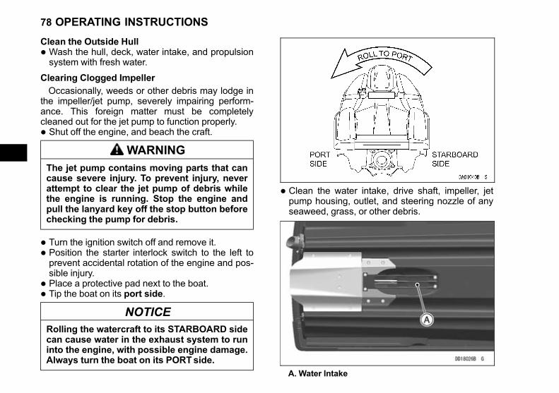
Black plate (78,1)
Clean the Outside Hull
• Wash the hull, deck, water intake, and propulsionsystem with fresh water.
Clearing Clogged Impeller
Occasionally, weeds or other debris may lodge inthe impeller/jet pump, severely impairing perform-ance. This foreign matter must be completelycleaned out for the jet pump to function properly.
• Shut off the engine, and beach the craft.
WARNINGThe jet pump contains moving parts that cancause severe injury. To prevent injury, neverattempt to clear the jet pump of debris whilethe engine is running. Stop the engine andpull the lanyard key off the stop button beforechecking the pump for debris.
• Turn the ignition switch off and remove it.
• Position the starter interlock switch to the left toprevent accidental rotation of the engine and pos-sible injury.
• Place a protective pad next to the boat.
• Tip the boat on its port side.
NOTICERolling the watercraft to its STARBOARD sidecan cause water in the exhaust system to runinto the engine, with possible engine damage.Always turn the boat on its PORTside.
• Clean the water intake, drive shaft, impeller, jetpump housing, outlet, and steering nozzle of anyseaweed, grass, or other debris.
A. Water Intake
78 OPERATING INSTRUCTIONS
Black plate (79,1)
NOTICEEngine cooling water is supplied by the jetpump, and any loss of pump performancemay cause overheating resulting in severeengine damage. To prevent overheating, besure the pump area and all its componentsare completely clear.
OPERATING INSTRUCTIONS 79
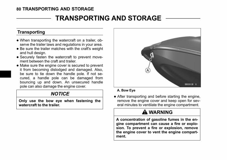
Black plate (80,1)
TRANSPORTING AND STORAGE
Transporting
• When transporting the watercraft on a trailer, ob-serve the trailer laws and regulations in your area.
• Be sure the trailer matches with the craft's weightand hull design.
• Securely fasten the watercraft to prevent move-ment between the craft and trailer.
• Make sure the engine cover is secured to preventit from becoming dislodged and damaged. Also,be sure to tie down the handle pole. If not se-cured, a handle pole can be damaged frombouncing up and down. An unsecured handlepole can also damage the engine cover.
NOTICEOnly use the bow eye when fastening thewatercraft to the trailer.
A. Bow Eye
• After transporting and before starting the engine,remove the engine cover and keep open for sev-eral minutes to ventilate the engine compartment.
WARNINGA concentration of gasoline fumes in the en-gine compartment can cause a fire or explo-sion. To prevent a fire or explosion, removethe engine cover to vent the engine compart-ment.
80 TRANSPORTING AND STORAGE
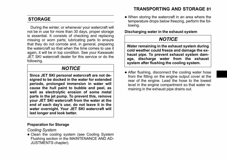
Black plate (81,1)
STORAGE
During the winter, or whenever your watercraft willnot be in use for more than 30 days, proper storageis essential. It consists of checking and replacingmissing or worn parts; lubricating parts to ensurethat they do not corrode and, in general, preparingthe watercraft so that when the time comes to use itagain, it will be in top condition. See your KawasakiJET SKI watercraft dealer for this service or do thefollowing.
NOTICESince JET SKI personal watercraft are not de-signed to be docked in the water for extendedperiods, prolonged immersion in water willcause the hull paint to bubble and peel, aswell as electrolytic erosion of some metalparts in the jet pump. To prevent this, removeyour JET SKI watercraft from the water at theend of each day's use; do not leave it in thewater overnight. Your JET SKI watercraft willlast longer and look better.
Preparation for Storage
Cooling System• Clean the cooling system (see Cooling SystemFlushing section in the MAINTENANCE AND AD-JUSTMENTS chapter).
• When storing the watercraft in an area where thetemperature drops below freezing, perform the fol-lowing.
Discharging water in the exhaust system
NOTICEWater remaining in the exhaust system duringcold weather could freeze and damage the ex-haust pipe. To prevent exhaust system dam-age, discharge water from the exhaustsystem after flushing the cooling system.
• After flushing, disconnect the cooling water hosefrom the fitting on the engine output cover at therear of the engine. Lead the hose to the lowestlevel in the engine compartment so that water re-maining in the exhaust pipe drains out.
TRANSPORTING AND STORAGE 81

Black plate (82,1)
A. Engine Output CoverB. FittingC. Cooling Water HoseD. Exhaust Pipe
A. Engine Output CoverB. Cooling Water HoseC. Air Box
• Connect the hose to the fitting on the engine out-put cover and tighten the clamp securely.
NOTICEIf the cooling water hose comes off during op-eration, water could swamp the boat, causingit to sink or severe engine damage.Connect the hose securely to the fitting.If you are not confident you can perform stor-age procedures, ask your Kawasaki JET SKIwatercraft dealer for this service.
Bilge System• Remove the engine cover.
82 TRANSPORTING AND STORAGE
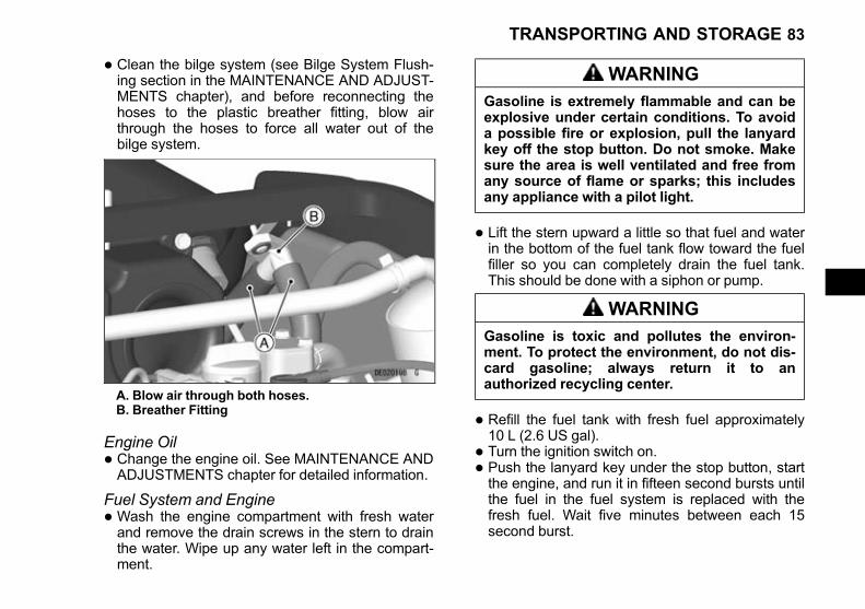
Black plate (83,1)
• Clean the bilge system (see Bilge System Flush-ing section in the MAINTENANCE AND ADJUST-MENTS chapter), and before reconnecting thehoses to the plastic breather fitting, blow airthrough the hoses to force all water out of thebilge system.
A. Blow air through both hoses.B. Breather Fitting
Engine Oil• Change the engine oil. See MAINTENANCE ANDADJUSTMENTS chapter for detailed information.
Fuel System and Engine• Wash the engine compartment with fresh waterand remove the drain screws in the stern to drainthe water. Wipe up any water left in the compart-ment.
WARNINGGasoline is extremely flammable and can beexplosive under certain conditions. To avoida possible fire or explosion, pull the lanyardkey off the stop button. Do not smoke. Makesure the area is well ventilated and free fromany source of flame or sparks; this includesany appliance with a pilot light.
• Lift the stern upward a little so that fuel and waterin the bottom of the fuel tank flow toward the fuelfiller so you can completely drain the fuel tank.This should be done with a siphon or pump.
WARNINGGasoline is toxic and pollutes the environ-ment. To protect the environment, do not dis-card gasoline; always return it to anauthorized recycling center.
• Refill the fuel tank with fresh fuel approximately10 L (2.6 US gal).
• Turn the ignition switch on.
• Push the lanyard key under the stop button, startthe engine, and run it in fifteen second bursts untilthe fuel in the fuel system is replaced with thefresh fuel. Wait five minutes between each 15second burst.
TRANSPORTING AND STORAGE 83

Black plate (84,1)
NOTICETo prevent overheating resulting in engineand exhaust system damage, do not run theengine with the watercraft out of the water formore than 15 seconds at a time.Never operate the engine at maximum speedout of the water.
• Drain the fuel tank as previously described.
• Leave the fuel filler cap loose to prevent conden-sation in the tank.
• Disconnect the two ignition coil connectors on theprimary ignition cables located at the left front ofthe engine.
A. Ignition Coil Connectors
• Remove all the spark plug caps.
• Remove all spark plugs.
• Spray fogging oil directly into each cylinder.
• Turn the engine over several times with the startbutton to coat the cylinder walls.
WARNINGAn air/oil mist will be forcibly ejected from thespark plug holes and could injure your eyes.To prevent eye injury, do not lean over the en-gine when performing this procedure. If gasdoes get in your eyes, immediately washthem with plenty of clean, fresh water andconsult a physician as soon as possible.
• Apply molybdenum disulfide grease to the threadsof the spark plugs, and reinstall them.
Spark Plugs Tightening Torque:13 N·m (1.3 kgf·m, 115 in·lb)
• Pull the lanyard key off the stop button and turnthe ignition switch off.
• Reinstall the spark plug caps.
• Reconnect the ignition coil connectors.
NOTE○Be sure to make correct connections (the connec-tor of the spark plug cables marked 2 & 3 with theconnector of the leads marked 2 & 3). Then, re-connect the other connector.
○Before reconnecting, apply a high quality water-proof marine grease to the connectors.
84 TRANSPORTING AND STORAGE
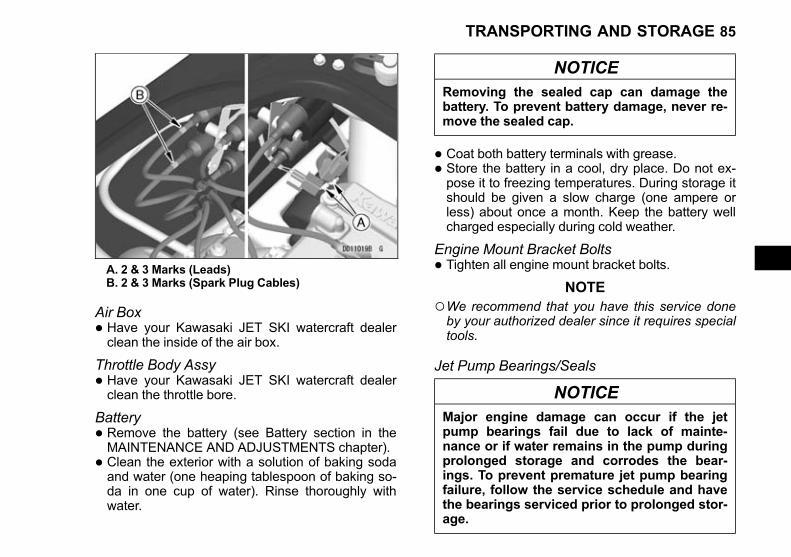
Black plate (85,1)
A. 2 & 3 Marks (Leads)B. 2 & 3 Marks (Spark Plug Cables)
Air Box• Have your Kawasaki JET SKI watercraft dealerclean the inside of the air box.
Throttle Body Assy• Have your Kawasaki JET SKI watercraft dealerclean the throttle bore.
Battery• Remove the battery (see Battery section in theMAINTENANCE AND ADJUSTMENTS chapter).
• Clean the exterior with a solution of baking sodaand water (one heaping tablespoon of baking so-da in one cup of water). Rinse thoroughly withwater.
NOTICERemoving the sealed cap can damage thebattery. To prevent battery damage, never re-move the sealed cap.
• Coat both battery terminals with grease.
• Store the battery in a cool, dry place. Do not ex-pose it to freezing temperatures. During storage itshould be given a slow charge (one ampere orless) about once a month. Keep the battery wellcharged especially during cold weather.
Engine Mount Bracket Bolts• Tighten all engine mount bracket bolts.
NOTE○We recommend that you have this service doneby your authorized dealer since it requires specialtools.
Jet Pump Bearings/Seals
NOTICEMajor engine damage can occur if the jetpump bearings fail due to lack of mainte-nance or if water remains in the pump duringprolonged storage and corrodes the bear-ings. To prevent premature jet pump bearingfailure, follow the service schedule and havethe bearings serviced prior to prolonged stor-age.
TRANSPORTING AND STORAGE 85

Black plate (86,1)
Have your Kawasaki dealer inspect the jet pumpbearings and seals after the first 25 hours of use orone year, whichever comes first; and then every 50hours or every year, whichever comes first. The jetpump bearings should also be serviced before anyprolonged storage to prevent any water that may beleft in the pump from corroding the bearings andcausing premature failure.
Cleaning• Wash the exterior and dry it thoroughly.
NOTICEHarsh cleaning solvents may attack the sur-face or smear the colors. To preserve the fin-ish, use only a mild detergent in water towash the watercraft.
• Lightly spray all exposed metal parts with a pene-trating rust inhibitor, such as WD40 or BEL-RAY 6in 1 to prevent corrosion.
• Install the engine cover loosely, and block it with10 mm (one half inch) spacers to insure adequateventilation and prevent condensation from form-ing.
• Cover the watercraft and store it in a clean, dryplace.
NOTICEWater left in the riding platform can cause thepaint to bubble and peel, and the mat to peeloff the deck. Do not allow water to collect inthe riding platform during storage. If thewatercraft is left outside, even covered, watercan collect in the riding platform. If the water-craft is left on a trailer, raise the trailer tongueso that water cannot accumulate in the ridingplatform.
Semi-gloss FinishTo clean the semi-gloss finish:
• When washing the watercraft, always use a mildneutral detergent and water.
• The semi-gloss finish effect may be lost if the fin-ish is excessively rubbed.
• If in any doubt, consult an authorized Kawasakidealer.
Lubrication• Carry out all recommended lubrication procedures(see Lubrication section in the MAINTENANCEAND ADJUSTMENTS chapter).
Removal from Storage
The following procedure explains the steps neces-sary to put the watercraft back in service following astorage period. See your Kawasaki JET SKI water-craft dealer for this service, or do the following. See
86 TRANSPORTING AND STORAGE

Black plate (87,1)
the MAINTENANCE AND ADJUSTMENTS chapterfor detailed procedures.
• Carry out all recommended lubrication procedures(see Lubrication section).
• Check for binding or sticking throttle or steering.The throttle lever must return fully when released.
• Check the spark plugs (see Spark Plugs section).
• Check all rubber hoses for weathering, cracking,or looseness.
• Check the cooling and bilge hoses for weathering,cracking, or looseness.
• Check that the drain screws in the stern are se-curely tightened.
• Clean the battery terminals and charge if neces-sary. Install the battery (see Battery section).
• Check the fire extinguisher for a full charge.
• Fill the fuel tank with fuel and close the filler capsecurely.
WARNINGGasoline is extremely flammable and can beexplosive under certain conditions. To avoida possible fire or explosion, pull the lanyardkey off the stop button. Do not smoke. Makesure the area is well ventilated and free fromany source of flame or sparks; this includesany appliance with a pilot light.
• After transporting or refueling and before startingthe engine, remove the engine cover and keepopen for several minutes to ventilate the enginecompartment.
WARNINGA concentration of gasoline fumes in the en-gine compartment can cause a fire or explo-sion. To prevent a fire or explosion, removethe engine cover to vent the engine compart-ment.
• Check for fuel leaks. Repair if necessary.
• Check the engine oil level. Fill with specified oil ifnecessary.
DANGERExhaust gas contains carbon monoxide, acolorless, odorless poisonous gas. Inhalingcarbon monoxide can cause serious brain in-jury or death. DO NOT run the engine in en-closed areas. Operate only in a well-ventilated area.
• Start the engine and run it for 15 seconds. Checkfor fuel, oil and exhaust leaks. Any leaks must berepaired.
NOTICETo prevent overheating resulting in engineand exhaust system damage, do not run theengine with the watercraft out of the water formore than 15 seconds at a time.Never operate the engine at maximum speedout of the water.
TRANSPORTING AND STORAGE 87
Black plate (88,1)
• Install the engine cover, making sure the enginecover latch is secure.
88 TRANSPORTING AND STORAGE

Black plate (89,1)
MAINTENANCE AND ADJUSTMENTS
The maintenance and adjustments outlined in this chapter must be carried out in accordance with the Peri-odic Maintenance Chart to keep the watercraft in good running condition. The initial maintenance is vitallyimportant and must not be neglected.With a basic knowledge of mechanics and the proper use of tools, you should be able to carry out many of
the maintenance items described in this chapter. If you lack proper experience or doubt your ability, all adjust-ments, maintenance, and repair work should be completed by a qualified technician.Please note that Kawasaki cannot assume any responsibility for damage resulting from incorrect or improper
adjustment made by the owner.
MAINTENANCE AND ADJUSTMENTS 89

Black plate (90,1)
EMISSION CONTROL INFORMATION
Emission Control InformationTo protect the environment in which we all live, Kawasaki has incorporated an exhaust emission control sys-
tem.
Exhaust Emission Control SystemThis system reduces the amount of pollutants discharged into the atmosphere by the exhaust of this engine.
The fuel, ignition and exhaust systems of this engine have been carefully designed and constructed to ensurean efficient engine with low exhaust pollutant levels.
Fuel InformationTHIS ENGINE IS CERTIFIED TO OPERATE ON UNLEADED GASOLINE ONLY.
A minimum of RON 91 is recommended.
Tampering with Exhaust Emission Control System ProhibitedDo not tamper with the original emission related parts.* Electronic Control Unit* Fuel Pump* Spark Plugs* Fuel Injectors* Throttle Body
Noise Emission Control SystemThis system reduces the amount of noise discharged into the atmosphere from this engine.The intake and exhaust silencing systems have been carefully designed and constructed to ensure to give
optimum performance while maintaining a low noise level.Please do not tamper with the following noise emission related parts.
PropellerExhaust ManifoldExhaust Pipe
90 MAINTENANCE AND ADJUSTMENTS
Black plate (91,1)
MufflerIntake Manifold
Maintenance and WarrantyProper maintenance is necessary to ensure that your watercraft will continue to have low emission levels.
This Owner's Manual contains those maintenance recommendations for your engine. Those items identified bythe Periodic Maintenance Chart are necessary to ensure compliance with the applicable standards.As the owner of the Personal Watercraft, you have the responsibility to make sure that the recommended
maintenance is carried out according to the instructions in this Owner's Manual at your own expense.The Kawasaki Limited Emission Control System Warranty requires that you return your Personal Watercraft
to an authorized Kawasaki Personal Watercraft dealer for remedy under warranty. Please read the warrantycarefully, and keep it valid by complying with the owner's obligations it contains.
MAINTENANCE AND ADJUSTMENTS 91
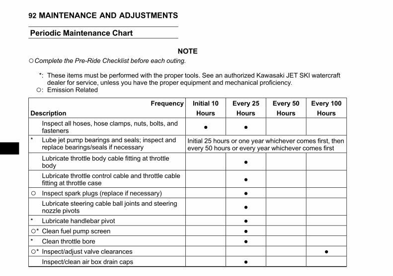
Black plate (92,1)
Periodic Maintenance Chart
NOTE○Complete the Pre-Ride Checklist before each outing.
*: These items must be performed with the proper tools. See an authorized Kawasaki JET SKI watercraftdealer for service, unless you have the proper equipment and mechanical proficiency.
○: Emission Related
Frequency Initial 10 Every 25 Every 50 Every 100
Description Hours Hours Hours Hours
Inspect all hoses, hose clamps, nuts, bolts, andfasteners • •
* Lube jet pump bearings and seals; inspect andreplace bearings/seals if necessary
Initial 25 hours or one year whichever comes first, thenevery 50 hours or every year whichever comes first
Lubricate throttle body cable fitting at throttlebody •Lubricate throttle control cable and throttle cablefitting at throttle case •
○ Inspect spark plugs (replace if necessary) •Lubricate steering cable ball joints and steeringnozzle pivots •
* Lubricate handlebar pivot •○* Clean fuel pump screen •* Clean throttle bore •○* Inspect/adjust valve clearances •
Inspect/clean air box drain caps •
92 MAINTENANCE AND ADJUSTMENTS

Black plate (93,1)
Frequency Initial 10 Every 25 Every 50 Every 100
Description Hours Hours Hours Hours
Replace engine oil•
(or everyyear)
* Replace engine oil filter •* Inspect/tighten engine mount bolts
•(or everyyear)
* Inspect fuel vent check valve •* Inspect/clean inside of air box •○ Inspect throttle control system •
Flush bilge line and filter •Flush cooling system (after each use in saltwater) •
* Inspect impeller blades for damage •* Inspect/replace coupling damper •○* Inspect throttle shaft spring (replace throttle body
if necessary) •* Inspect steering cable •
Inspect hull drain screws (replace if necessary) •Inspect battery terminals and charging condition •
* Replace fuel hoses Every 5 years
MAINTENANCE AND ADJUSTMENTS 93

Black plate (94,1)
Control Cables
Throttle Cable Play InspectionThere must be play in the throttle mechanism.
• Measure the distance the throttle lever moves be-fore the engine begins to pick up speed. Playshould be about 2 mm (0.08 in.).
• If there is improper play, adjust it.
A. Throttle LeverB. About 2 mm (0.08 in.)
Throttle Cable Play Adjustment• Loosen and turn the locknuts at the end of thethrottle cable until the suitable free play is ob-tained.
• Tighten the locknuts securely.
A. Throttle CableB. LocknutsC. Throttle Body Assy
Steering Cable Adjustment• Center the handlebars in a straight ahead steeringposition.
94 MAINTENANCE AND ADJUSTMENTS
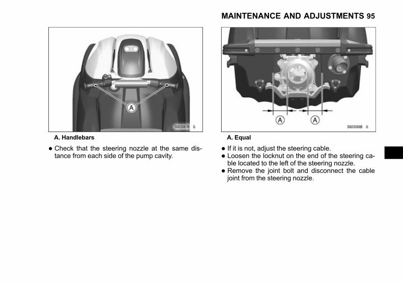
Black plate (95,1)
A. Handlebars
• Check that the steering nozzle at the same dis-tance from each side of the pump cavity.
A. Equal
• If it is not, adjust the steering cable.
• Loosen the locknut on the end of the steering ca-ble located to the left of the steering nozzle.
• Remove the joint bolt and disconnect the cablejoint from the steering nozzle.
MAINTENANCE AND ADJUSTMENTS 95
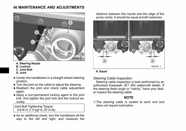
Black plate (96,1)
A. Steering NozzleB. LocknutC. Joint BoltD. Joint
• Center the handlebars in a straight ahead steeringposition.
• Turn the joint on the cable to adjust the steering.
• Reattach the joint and check cable adjustmentagain.
• Apply a non-permanent locking agent to the jointbolt. And tighten the joint bolt and the locknut se-curely.
Joint Bolt Tightening Torque:9.8 N·m (1.0 kgf·m, 87 in·lb)
• As an additional check, turn the handlebars all theway to the left and right, and measure the
distance between the nozzle and the edge of thepump cavity. It should be equal at both extremes.
A. Equal
Steering Cable InspectionSteering cable inspection is best performed by an
authorized Kawasaki JET SKI watercraft dealer. Ifthe steering feels rough or “catchy,” have your deal-er inspect the steering cable.
NOTE○The steering cable is sealed at each end anddoes not require lubrication.
96 MAINTENANCE AND ADJUSTMENTS

Black plate (97,1)
Fuel System
Throttle Adjustments
Idle SpeedIdle speed adjustment is best performed by your
authorized Kawasaki JET SKI watercraft dealer. Ifthe idle speed is unstable, have your dealer inspectthe throttle body.
Idle Speed
1 300 ±100 rpm - in water
1 300 ±100 rpm - out of water
High Altitude UseHigh altitude adjustment is not required as the
ECU (Electronic Control Unit) controls the air/fuelmixture automatically.
Fuel Vent Check Valve
The fuel tank is equipped with a vent hose. Asmall plastic check valve mounted in the vent hoseallows air to enter the tank, but minimizes fuel spill-age when the craft is tipped over. Have the checkvalve inspected in accordance with the PeriodicMaintenance Chart by your authorized KawasakiJET SKI watercraft dealer.
A. Check ValveB. Flow Direction
Fuel Pump Screen
The watercraft fuel pump is equipped with fuelpump screens to prevent dirt or other foreign materi-al from entering the fuel line.Have your Kawasaki JET SKI watercraft dealer
clean the fuel pump screen in accordance with thePeriodic Maintenance Chart.
Fuel Hose
The rubber fuel hose deteriorates over time. Be-fore boarding the watercraft, before prolonged stor-age and after prolonged storage, have yourauthorized JET SKI watercraft dealer check the fuelsystem.
MAINTENANCE AND ADJUSTMENTS 97
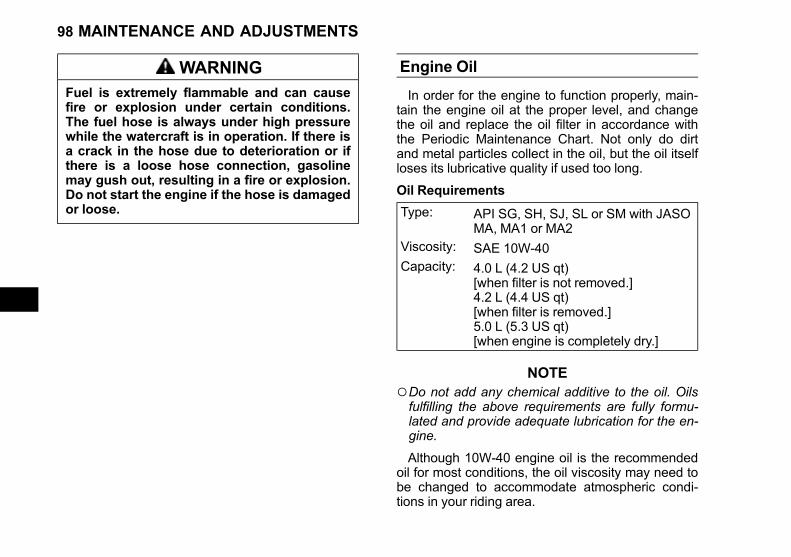
Black plate (98,1)
WARNINGFuel is extremely flammable and can causefire or explosion under certain conditions.The fuel hose is always under high pressurewhile the watercraft is in operation. If there isa crack in the hose due to deterioration or ifthere is a loose hose connection, gasolinemay gush out, resulting in a fire or explosion.Do not start the engine if the hose is damagedor loose.
Engine Oil
In order for the engine to function properly, main-tain the engine oil at the proper level, and changethe oil and replace the oil filter in accordance withthe Periodic Maintenance Chart. Not only do dirtand metal particles collect in the oil, but the oil itselfloses its lubricative quality if used too long.
Oil Requirements
Type: API SG, SH, SJ, SL or SM with JASOMA, MA1 or MA2
Viscosity: SAE 10W-40Capacity: 4.0 L (4.2 US qt)
[when filter is not removed.]4.2 L (4.4 US qt)[when filter is removed.]5.0 L (5.3 US qt)[when engine is completely dry.]
NOTE○Do not add any chemical additive to the oil. Oilsfulfilling the above requirements are fully formu-lated and provide adequate lubrication for the en-gine.
Although 10W-40 engine oil is the recommendedoil for most conditions, the oil viscosity may need tobe changed to accommodate atmospheric condi-tions in your riding area.
98 MAINTENANCE AND ADJUSTMENTS
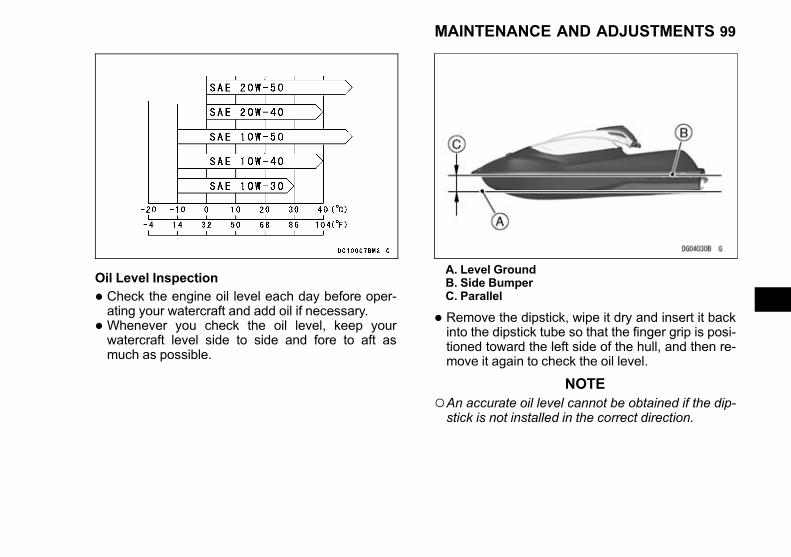
Black plate (99,1)
Oil Level Inspection
• Check the engine oil level each day before oper-ating your watercraft and add oil if necessary.
• Whenever you check the oil level, keep yourwatercraft level side to side and fore to aft asmuch as possible.
A. Level GroundB. Side BumperC. Parallel
• Remove the dipstick, wipe it dry and insert it backinto the dipstick tube so that the finger grip is posi-tioned toward the left side of the hull, and then re-move it again to check the oil level.
NOTE○An accurate oil level cannot be obtained if the dip-stick is not installed in the correct direction.
MAINTENANCE AND ADJUSTMENTS 99

Black plate (100,1)
A. DipstickB. Dipstick TubeC. Left Side
• The oil level must be between the “H” (High) and“L” (Low) level on the stick. Use the cold levelmark.
NOTE○Be careful when reading the dipstick as differentlevel marks on the dipstick should be used de-pending if the oil is warm or cold. See the next il-lustration.
A. DipstickB. “H” (High) Level when coldC. “H” (High) Level when hotD. “L” (Low) Level when coldE. “L” (Low) Level when hot
• If the oil level is too low, add oil up to the Low Lev-el. Use the same type and brand of oil that is al-ready in the engine.
NOTICEDirt and other foreign materials can causeserious engine damage. To prevent enginedamage, do not allow dirt or foreign materialsto enter the engine.
100 MAINTENANCE AND ADJUSTMENTS

Black plate (101,1)
Oil Change
In accordance with the Maintenance Chart,change the engine oil as follows:
• Level the watercraft port to starboard as well asfore to aft.
• In a well-ventilated area, start the engine whileflushing the cooling system.
NOTICEThe engine must be running before the wateris turned on and the water must be turned offbefore the engine is stopped.Do not run the engine without cooling waterflow for more than 15 seconds.
• Warm up the engine and stop it.
• Remove the oil filler cap and the dipstick.
A. Oil Filler CapB. Dipstick
NOTICEDirt and other foreign materials can causeserious engine damage. To prevent enginedamage, do not allow dirt or foreign materialsto enter the engine.
• Drain the oil thoroughly from the dipstick tube us-ing a commercially-available vacuum pump.
WARNINGUsed engine oil is toxic and pollutes the envi-ronment. To protect the environment, do notdiscard used engine oil; always return it to anauthorized recycling center.
MAINTENANCE AND ADJUSTMENTS 101
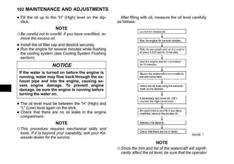
Black plate (102,1)
• Fill the oil up to the “H” (High) level on the dip-stick.
NOTE○Be careful not to overfill. If you have overfilled, re-move the excess oil.
• Install the oil filler cap and dipstick securely.
• Run the engine for several minutes while flushingthe cooling system (see Cooling System Flushingsection).
NOTICEIf the water is turned on before the engine isrunning, water may flow back through the ex-haust pipe and into the engine, causing se-vere engine damage. To prevent enginedamage, be sure the engine is running beforeturning the water on.
• The oil level must be between the “H” (High) and“L” (Low) level again on the stick.
• Check that there are no oil leaks in the enginecompartment.
NOTE○This procedure requires mechanical skills andtools. If it is beyond your capability, ask your Ka-wasaki dealer for the service.
After filling with oil, measure the oil level carefullyas follows:
NOTE○Since the trim and list of the watercraft will signifi-cantly affect the oil level, be sure that the operator
102 MAINTENANCE AND ADJUSTMENTS

Black plate (103,1)
and/or luggage are not aboard the watercraftwhen measuring the oil level. Also fill up the fueltank if it is not full.
○This measuring procedure with the watercraftafloat should be followed if the oil level needs tobe topped up.
Spark Plugs
Since the engine is water-cooled and is generallyoperated at a constant throttle opening, cylinderhead temperature is relatively stable. For this rea-son, if the engine is in good condition and properlytuned, it should not be necessary to use a sparkplug of a different heat range. Since a spark plug ofthe wrong heat range can cause extensive enginedamage, only the standard spark plug is recom-mended.
Standard Spark Plug
Standard Plug NGK CR9EKB
Terminal Solid Post Terminal
Plug Gap0.7 ~ 0.8 mm (0.028 ~ 0.031in.)
Tightening Torque 13 N·m (1.3 kgf·m, 115 in·lb)
MAINTENANCE AND ADJUSTMENTS 103

Black plate (104,1)
A. Terminal (Solid Post)B. Plug Gap
Spark Plug Inspection and Replacement• Remove the spark plugs and inspect the ceramicinsulators. The appearance of the insulators re-flects the efficiency of the combustion process.When the engine is operating properly, the pluginsulators should be clean and a light brown color.If the insulators look glazed or very white, if theelectrodes appear overheated, or if there are graymetallic deposits on the plugs, combustion cham-ber temperatures are too high. Inspection shouldbe done by an authorized Kawasaki JET SKIwatercraft dealer.
NOTICEExcessive operating temperature can causeserious engine damage. To prevent enginedamage, the cause for any excessive operat-ing temperature should be located and cor-rected immediately.
• A dry, sooty black deposit on the insulators indi-cates an overly rich fuel/air mixture. Check for cor-rect throttle control cable adjustment. Inspectionshould be done by an authorized Kawasaki JETSKI watercraft dealer.
• Inspect the condition of the spark plug. If thespark plug electrodes are rounded, damaged, thecarbon is accumulated, or the insulator is cracked,replace the plug.
• Measure the spark plug gap. Use a wire-typethickness gauge to prevent possible damage tothe electrode.
NOTICEDo not adjust the plug gap. If the plug gap isout of the specification, replace the sparkplug.
NOTE○If the plug is oily or has carbon build-up, clean itby using a high flash-point solvent and nonmetalbrush (nylon etc.).
104 MAINTENANCE AND ADJUSTMENTS
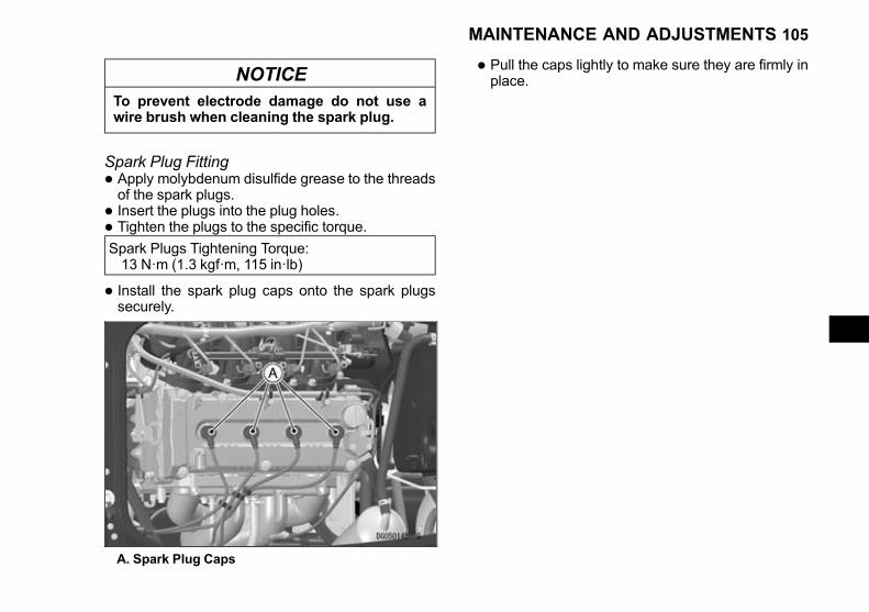
Black plate (105,1)
NOTICETo prevent electrode damage do not use awire brush when cleaning the spark plug.
Spark Plug Fitting• Apply molybdenum disulfide grease to the threadsof the spark plugs.
• Insert the plugs into the plug holes.
• Tighten the plugs to the specific torque.
Spark Plugs Tightening Torque:13 N·m (1.3 kgf·m, 115 in·lb)
• Install the spark plug caps onto the spark plugssecurely.
A. Spark Plug Caps
• Pull the caps lightly to make sure they are firmly inplace.
MAINTENANCE AND ADJUSTMENTS 105

Black plate (106,1)
Battery
The battery is located in the engine room.The battery installed in this watercraft is a sealed
type, and the sealing strip should not be removed atany time after the specified electrolyte has been in-stalled in the battery for initial service. It is not nec-essary to check the battery electrolyte level or adddistilled water.
DANGER
• Battery acid generates hydrogen gas whichis flammable and explosive under certainconditions. It is present within a battery atall times, even in a discharged condition.Keep all flames and sparks (cigarettes)away from the battery.
• Wear eye protection when working with abattery. In the event of battery acid contactwith skin, eyes, or clothing, wash the af-fected areas immediately with water for atleast five minutes. Seek medical attention.
NOTICERemoving the sealed cap can damage thebattery. To avoid damaging the battery, neverremove the sealed cap. Using a conventionalbattery in this watercraft will cause the electri-cal system to malfunction. Do not install aconventional battery.
Make Yuasa Battery
Type YTX20L-BS
Battery Removal
A. Positive Cable (Red)B. Negative Cable (Black)C. Straps
Battery Cable Removal
• Make sure the ignition switch is turned off beforestarting this procedure.
106 MAINTENANCE AND ADJUSTMENTS
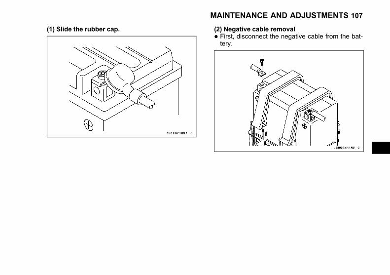
Black plate (107,1)
(1) Slide the rubber cap. (2) Negative cable removal
• First, disconnect the negative cable from the bat-tery.
MAINTENANCE AND ADJUSTMENTS 107

Black plate (108,1)
(3) Positive cable removal
• Next, disconnect the positive cable from the bat-tery.
(4) Battery removal
• Release the tags of the hold-down straps from thehooks.
108 MAINTENANCE AND ADJUSTMENTS

Black plate (109,1)
• Remove the spark plug cap #1.
• Remove the battery from the port side.
A. Spark Plug Cap #1
Battery Inspection and Maintenance(1) Battery terminal oxidation/corrosion (coatedwith patina/white powder)<Cleaning>
1. Apply a penetrating lubricating spray.2. Leave it for five minutes.3. Wipe off with a cloth or polish with a fine emery
cloth or wire brush.
A. Oxidation/Corrosion
MAINTENANCE AND ADJUSTMENTS 109

Black plate (110,1)
(2) Battery terminal damage (deformation,cracks, dents)
• If there are any deformation, cracks, or dents, re-place the battery.
A. DeformationB. Dents
(3) Battery inspection
• Check the battery for deformation or cracks.
A. LooseB. CracksC. Deformation
110 MAINTENANCE AND ADJUSTMENTS

Black plate (111,1)
(4) Hold-down strap inspection
• Check the hold-down strap for deterioration suchas cutting, cracking, or looseness.
(5) Battery tray cleaning
• Inspect the battery tray and remove dust.
MAINTENANCE AND ADJUSTMENTS 111

Black plate (112,1)
Battery Installation1. Battery installation and fixation
• Install the battery from the port side.
• Install the spark plug cap #1.
• Pull the cap lightly to make sure it is firmly inplace.
• Secure the battery with the straps and make surethat it is firmly fixed.
2. Cable connection
• Connect the positive cable to the battery first.
(1) Temporal tightening
• Pay attention to the cable terminal direction andconnect the cable so that the battery terminal andcable terminal are in close contact.
NOTICEReversing the battery connections will dam-age the electrical system. To prevent damage,be sure the battery connections are correct.
112 MAINTENANCE AND ADJUSTMENTS

Black plate (113,1)
(2) Tightening
• Tighten the terminal screws securely with awrench.
• Tighten the positive terminal first, then tighten thenegative terminal.
(3) Confirmation of battery cable fixation
• After tightening both terminals securely, move thecable terminals from side to side and make surethat the cables are fixed and do not move.
MAINTENANCE AND ADJUSTMENTS 113
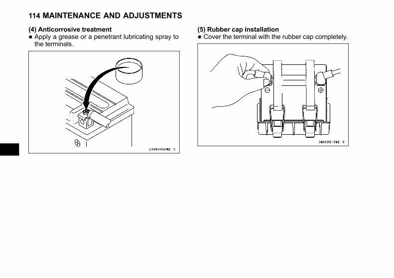
Black plate (114,1)
(4) Anticorrosive treatment
• Apply a grease or a penetrant lubricating spray tothe terminals.
(5) Rubber cap installation
• Cover the terminal with the rubber cap completely.
114 MAINTENANCE AND ADJUSTMENTS

Black plate (115,1)
Precaution for connecting the cable
(1) To prevent a loose cable connection, do notuse a long bolt
(2) To prevent a loose electrical connection, donot use a wire.
MAINTENANCE AND ADJUSTMENTS 115
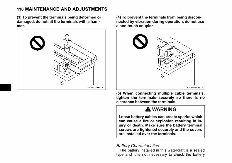
Black plate (116,1)
(3) To prevent the terminals being deformed ordamaged, do not hit the terminals with a ham-mer.
(4) To prevent the terminals from being discon-nected by vibration during operation, do not usea one-touch coupler.
(5) When connecting multiple cable terminals,tighten the terminals securely so there is noclearance between the terminals.
WARNINGLoose battery cables can create sparks whichcan cause a fire or explosion resulting in in-jury or death. Make sure the battery terminalscrews are tightened securely and the coversare installed over the terminals.
Battery CharacteristicsThe battery installed in this watercraft is a sealed
type and it is not necessary to check the battery
116 MAINTENANCE AND ADJUSTMENTS
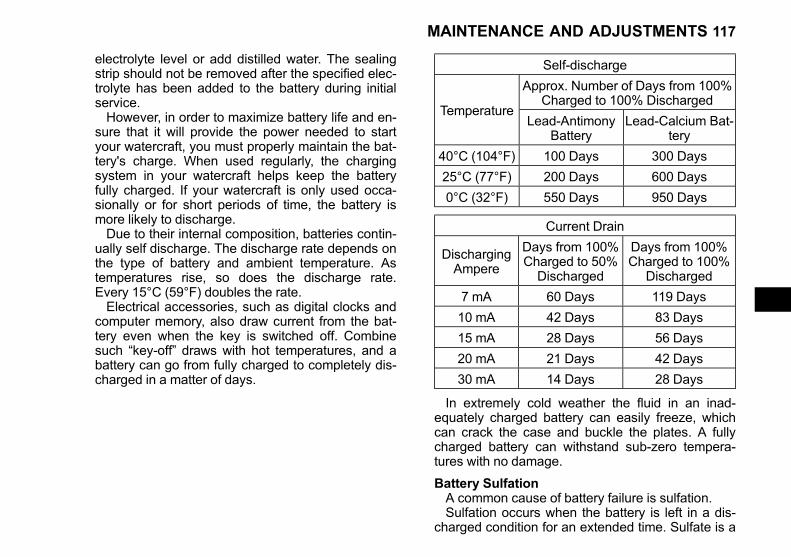
Black plate (117,1)
electrolyte level or add distilled water. The sealingstrip should not be removed after the specified elec-trolyte has been added to the battery during initialservice.However, in order to maximize battery life and en-
sure that it will provide the power needed to startyour watercraft, you must properly maintain the bat-tery's charge. When used regularly, the chargingsystem in your watercraft helps keep the batteryfully charged. If your watercraft is only used occa-sionally or for short periods of time, the battery ismore likely to discharge.Due to their internal composition, batteries contin-
ually self discharge. The discharge rate depends onthe type of battery and ambient temperature. Astemperatures rise, so does the discharge rate.Every 15°C (59°F) doubles the rate.Electrical accessories, such as digital clocks and
computer memory, also draw current from the bat-tery even when the key is switched off. Combinesuch “key-off” draws with hot temperatures, and abattery can go from fully charged to completely dis-charged in a matter of days.
Self-discharge
Temperature
Approx. Number of Days from 100%Charged to 100% Discharged
Lead-AntimonyBattery
Lead-Calcium Bat-tery
40°C (104°F) 100 Days 300 Days
25°C (77°F) 200 Days 600 Days
0°C (32°F) 550 Days 950 Days
Current Drain
DischargingAmpere
Days from 100%Charged to 50%
Discharged
Days from 100%Charged to 100%
Discharged
7 mA 60 Days 119 Days
10 mA 42 Days 83 Days
15 mA 28 Days 56 Days
20 mA 21 Days 42 Days
30 mA 14 Days 28 Days
In extremely cold weather the fluid in an inad-equately charged battery can easily freeze, whichcan crack the case and buckle the plates. A fullycharged battery can withstand sub-zero tempera-tures with no damage.
Battery SulfationA common cause of battery failure is sulfation.Sulfation occurs when the battery is left in a dis-
charged condition for an extended time. Sulfate is a
MAINTENANCE AND ADJUSTMENTS 117

Black plate (118,1)
normal by product of the chemical reactions within abattery. But when continuous discharge allows thesulfate to crystallize in the cells, the battery platesbecome permanently damaged and will not hold acharge. Battery failure due to sulfation is not war-rantable.
Battery MaintenanceIt is the owner's responsibility to keep the battery
fully charged. Failure to do so can lead to batteryfailure and leave you stranded.If you are riding your watercraft infrequently, in-
spect the battery voltage weekly using a voltmeter.If it drops below 12.6 volts, the battery should becharged using an appropriate charger (check withyour Kawasaki dealer or visit by Kawasaki.com) at arate (amperage × hours) that is indicated on the bat-tery. If it is not possible to read the rate, charge thebattery at an amperage that is about 1/10th of thebattery capacity.If you will not be using your watercraft for longer
than two weeks, the battery should be charged us-ing an appropriate charger. Do not use an automo-tive-type quick charger that may overcharge thebattery and damage it.
NOTE○Leaving the battery connected causes the electri-cal components to discharge the battery and mayeven over discharge it. In this case, the repair orreplacement of the battery is not included in thewarranty. If you do not drive for four weeks ormore, disconnect the battery from the vehicle.
Kawasaki-recommended chargers are:
• Battery Mate 150-9
• OptiMate 4
• Yuasa MB-2040/2060
• Christie C10122SIf the above chargers are not available, use an
equivalent one.For more details, ask your Kawasaki dealer.
Battery Charging• Remove the battery from the watercraft (see Bat-tery Removal).
• Set the battery charge timer to the position indi-cated by the tester.
• Follow the battery charger instructions and chargethe battery.
NOTICERemoving the sealed cap can damage thebattery. To avoid damaging the battery, neverremove the sealed cap.Using a conventional battery in this watercraftwill cause the electrical system to malfunc-tion. Do not install a conventional battery.
NOTE○If you charge the sealed type battery, follow the in-structions on the battery label exactly.
118 MAINTENANCE AND ADJUSTMENTS

Black plate (119,1)
Lubrication
As in all marine craft, adequate lubrication andcorrosion protection is an absolute necessity to pro-vide long, reliable service. Refer to the PeriodicMaintenance Chart and PRE-RIDE CHECK chap-ter for the frequency of the following items:
• Lubricate the following with a penetrating rust in-hibitor, such as WD40 or BEL-RAY 6 in 1:
Lubricate the Throttle Control Cable with a Pres-sure Cable Luber
Steering Nozzle Pivots
A. Steering Nozzle Pivots
• Lubricate the following with a high quality water-proof marine grease.
MAINTENANCE AND ADJUSTMENTS 119
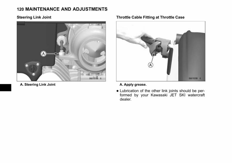
Black plate (120,1)
Steering Link Joint
A. Steering Link Joint
Throttle Cable Fitting at Throttle Case
A. Apply grease.
• Lubrication of the other link joints should be per-formed by your Kawasaki JET SKI watercraftdealer.
120 MAINTENANCE AND ADJUSTMENTS

Black plate (121,1)
Cooling System Flushing
To prevent major engine damage, you must per-form the following procedure to expel excess waterfrom the exhaust system. This helps prevent prema-ture wear due to internal engine corrosion and thebuild up of salt or other mineral deposits that canlead to cooling system blockage and overheating.Flush the system according to the Periodic Mainte-nance Chart, after each use in salt water, or when-ever there is reduced water flow from the bypassoutlet on the right side of the hull.This procedure is also used to provide auxiliary
cooling when the craft is out of the water (for exam-ple during an engine oil change).
• The auxiliary water supply port is located underthe engine cover.
A. CapB. Intake Fitting (Water Supply Port)
To Flush the Engine Cooling System
• Remove the cap and connect a garden hose witha screw-in fitting on its end.
• Start the engine and allow it to idle before turningon the water.
NOTICEIf the water is turned on before the engine isrunning, water may flow back through the ex-haust pipe and into the engine, causing se-vere engine damage. To prevent enginedamage, be sure the engine is running beforeturning the water on.
MAINTENANCE AND ADJUSTMENTS 121
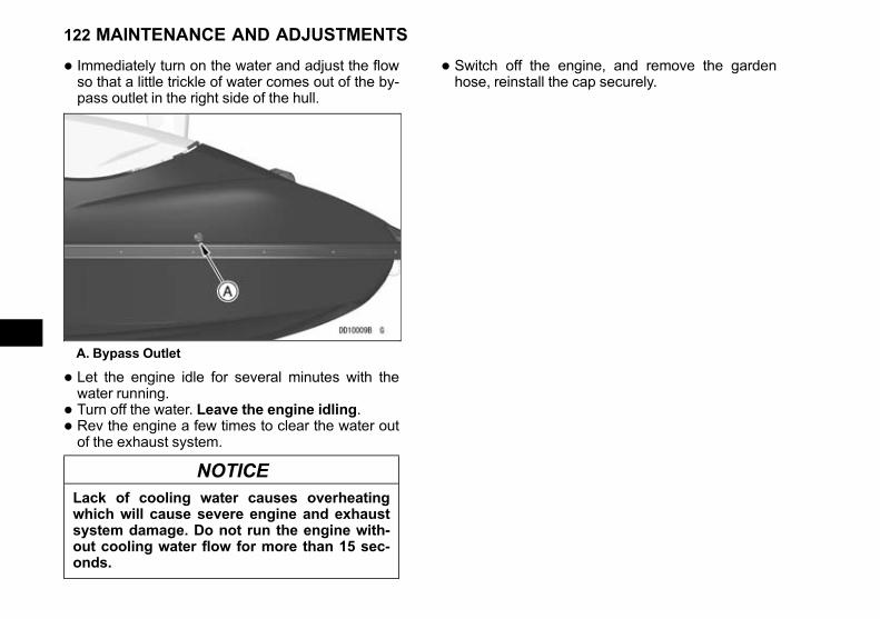
Black plate (122,1)
• Immediately turn on the water and adjust the flowso that a little trickle of water comes out of the by-pass outlet in the right side of the hull.
A. Bypass Outlet
• Let the engine idle for several minutes with thewater running.
• Turn off the water. Leave the engine idling.
• Rev the engine a few times to clear the water outof the exhaust system.
NOTICELack of cooling water causes overheatingwhich will cause severe engine and exhaustsystem damage. Do not run the engine with-out cooling water flow for more than 15 sec-onds.
• Switch off the engine, and remove the gardenhose, reinstall the cap securely.
122 MAINTENANCE AND ADJUSTMENTS
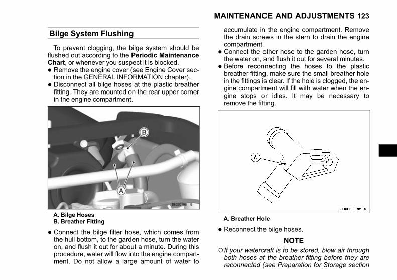
Black plate (123,1)
Bilge System Flushing
To prevent clogging, the bilge system should beflushed out according to the Periodic MaintenanceChart, or whenever you suspect it is blocked.
• Remove the engine cover (see Engine Cover sec-tion in the GENERAL INFORMATION chapter).
• Disconnect all bilge hoses at the plastic breatherfitting. They are mounted on the rear upper cornerin the engine compartment.
A. Bilge HosesB. Breather Fitting
• Connect the bilge filter hose, which comes fromthe hull bottom, to the garden hose, turn the wateron, and flush it out for about a minute. During thisprocedure, water will flow into the engine compart-ment. Do not allow a large amount of water to
accumulate in the engine compartment. Removethe drain screws in the stern to drain the enginecompartment.
• Connect the other hose to the garden hose, turnthe water on, and flush it out for several minutes.
• Before reconnecting the hoses to the plasticbreather fitting, make sure the small breather holein the fittings is clear. If the hole is clogged, the en-gine compartment will fill with water when the en-gine stops or idles. It may be necessary toremove the fitting.
A. Breather Hole
• Reconnect the bilge hoses.
NOTE○If your watercraft is to be stored, blow air throughboth hoses at the breather fitting before they arereconnected (see Preparation for Storage section
MAINTENANCE AND ADJUSTMENTS 123

Black plate (124,1)
in the TRANSPORTING AND STORAGE chap-ter). Jet Pump Bearings/Seals
NOTICEMajor engine damage can result if the jetpump bearings fail due to lack of mainte-nance. To help prevent this, follow the peri-odic maintenance schedule for the jet pumpbearings.
Have your Kawasaki dealer inspect the jet pumpbearings and seals after the first 25 hours of use orone year, whichever comes first; and then every 50hours or every year, whichever comes first. The jetpump bearings should also be serviced before anyprolonged storage to prevent any water that may beleft in the pump from corroding the bearings andcausing premature failure.
124 MAINTENANCE AND ADJUSTMENTS

Black plate (125,1)
Fuses
A 20 A main fuse is installed in the fuse case lo-cated in the engine room. If a fuse fails during oper-ation, inspect the electrical system to determine thecause, and then replace it with a new fuse of properamperage.
A. Main Fuse
NOTICEIncorrect fuses can damage the electrical sys-tem and may lead to a fire. To prevent damageand fire, do not substitute fuses. Replace theblown fuse with a new one of the correct ca-pacity, as specified on the electric case.
A. NormalB. Failed
MAINTENANCE AND ADJUSTMENTS 125

Black plate (126,1)
IN AN EMERGENCY
Troubleshooting Guide
If this procedure does not identify your problem, see your JET SKI watercraft dealer.
126 IN AN EMERGENCY

Black plate (127,1)
IN AN EMERGENCY 127
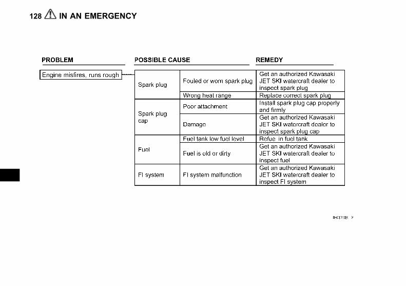
Black plate (128,1)
128 IN AN EMERGENCY

Black plate (129,1)
WARNINGFaulty steering can cause an accident resulting in serious injury or death. To help prevent an acci-dent, have any steering problems examined by an authorized Kawasaki JET SKI watercraft dealer.
IN AN EMERGENCY 129

Black plate (130,1)
In the Case of Emergency
Towing the JET SKI watercraft
Refer to the Towing section in the GENERAL IN-FORMATION chapter.
Jump Starting
If your watercraft's battery is run down, it shouldbe removed and charged. If this is not practical, abooster battery and jumper cables may be used tostart the engine. The booster battery must be of thesame voltage as the watercraft battery (12 V).
DANGER
• Battery acid generates hydrogen gas whichis flammable and explosive under certainconditions. It is present within a battery atall times, even in a discharged condition.Keep all flames and sparks (cigarettes)away from the battery.
• Wear eye protection when working with abattery. In the event of battery acid contactwith skin, eyes, or clothing, wash the af-fected areas immediately with water for atleast five minutes. Seek medical attention.
• Turn the ignition switch off.
• Remove the engine cover.
• Connect a jumper cable between the positive (+)terminals of the two batteries.
• Connect one end of the remaining jumper cable tothe negative (–) terminal of the booster battery.
NOTICEConnecting two batteries in reverse polarity(+ to –) can seriously damage the electricalsystem. To prevent electrical system damage,be sure the cables are connected to the cor-rect terminals.
A. Positive CableB. Battery
130 IN AN EMERGENCY
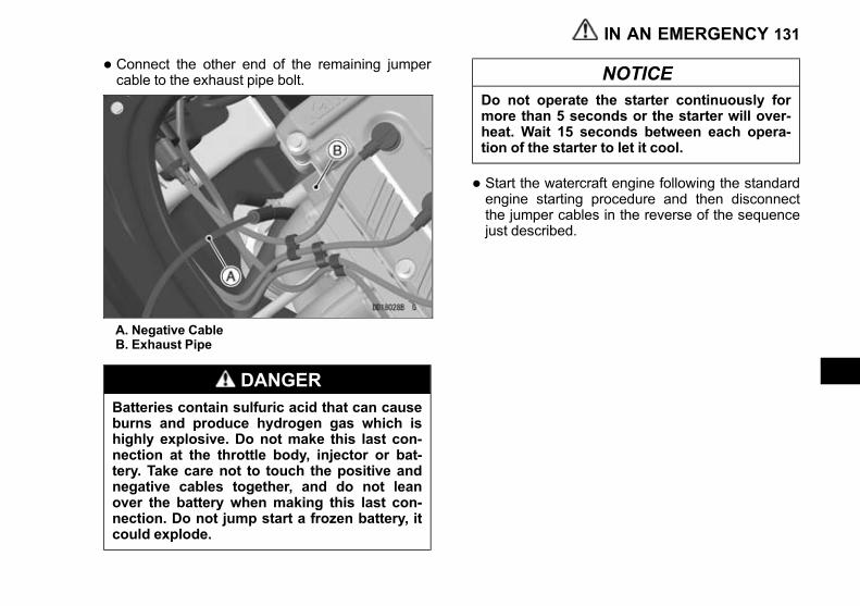
Black plate (131,1)
• Connect the other end of the remaining jumpercable to the exhaust pipe bolt.
A. Negative CableB. Exhaust Pipe
DANGERBatteries contain sulfuric acid that can causeburns and produce hydrogen gas which ishighly explosive. Do not make this last con-nection at the throttle body, injector or bat-tery. Take care not to touch the positive andnegative cables together, and do not leanover the battery when making this last con-nection. Do not jump start a frozen battery, itcould explode.
NOTICEDo not operate the starter continuously formore than 5 seconds or the starter will over-heat. Wait 15 seconds between each opera-tion of the starter to let it cool.
• Start the watercraft engine following the standardengine starting procedure and then disconnectthe jumper cables in the reverse of the sequencejust described.
IN AN EMERGENCY 131

Black plate (132,1)
APPENDIX
ENVIRONMENTAL PROTECTION
To help preserve the environment, properly discard used batteries, oils and fluids, or other vehicle compo-nents that you might dispose of in the future. Consult your authorized Kawasaki dealer or local environmentalwaste agency for their proper disposal procedure. This also applies to disposal of the entire vehicle at the endof its life.
Do not contaminate beaches, coasts, and waters with spilled fuel or oil and take care to preserve natural hab-itats and living things.
132 APPENDIX

Black plate (133,1)
SPECIFICATIONS
JET SKI WATERCRAFT - MODEL JS1500A CATEGORY C
Maximum Number of Ridersand Load Limit:Maximum Number of Riders 1 person
Load Limit 75 kg including rider and luggage 165 lb
Engine:Type 4-stroke, 4-cylinder, DOHC, 4-valve, water-cooled
Displacement 1 498 cm³ 91.41 cu in.
Bore and Stroke 83 × 69.2 mm 3.27 × 2.72 in.
Compression Ratio 10.6:1
Ignition System Digital transistor
Lubrication System Semi-drysump
Fuel System Digital fuel injectionResearch Octane Number(RON)
Minimum Rating 91
Starting System Electric starter
Tuning Specifications:
Spark Plug: NGK CR9EKB
Gap 0.7 ~ 0.8 mm 0.028 ~ 0.031 in.
Terminal Solid post terminalIgnition Timing 3° ATDC @1 300 r/min (rpm) ~ 32° BTDC @3 000 r/min
(rpm)
Idle Speed 1 300 ±100 r/min (rpm) - in water
APPENDIX 133
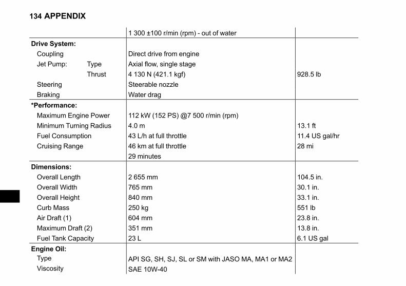
Black plate (134,1)
1 300 ±100 r/min (rpm) - out of water
Drive System:
Coupling Direct drive from engine
Jet Pump: Type Axial flow, single stage
Thrust 4 130 N (421.1 kgf) 928.5 lb
Steering Steerable nozzle
Braking Water drag
*Performance:
Maximum Engine Power 112 kW (152 PS) @7 500 r/min (rpm)
Minimum Turning Radius 4.0 m 13.1 ft
Fuel Consumption 43 L/h at full throttle 11.4 US gal/hr
Cruising Range 46 km at full throttle 28 mi
29 minutes
Dimensions:
Overall Length 2 655 mm 104.5 in.
Overall Width 765 mm 30.1 in.
Overall Height 840 mm 33.1 in.
Curb Mass 250 kg 551 lb
Air Draft (1) 604 mm 23.8 in.
Maximum Draft (2) 351 mm 13.8 in.
Fuel Tank Capacity 23 L 6.1 US gal
Engine Oil:Type API SG, SH, SJ, SL or SM with JASO MA, MA1 or MA2Viscosity SAE 10W-40
134 APPENDIX
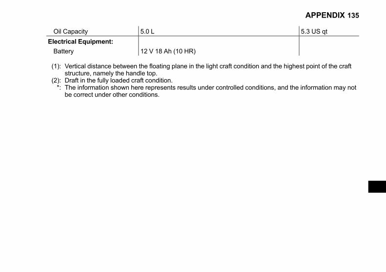
Black plate (135,1)
Oil Capacity 5.0 L 5.3 US qt
Electrical Equipment:
Battery 12 V 18 Ah (10 HR)
(1): Vertical distance between the floating plane in the light craft condition and the highest point of the craftstructure, namely the handle top.
(2): Draft in the fully loaded craft condition.*: The information shown here represents results under controlled conditions, and the information may not
be correct under other conditions.
APPENDIX 135

Black plate (136,1)
Serial Numbers
The craft and engine identification numbers are used to register the boat. They are the only means of identify-ing your particular machine from others of the same model. These serial numbers may be needed by your deal-er when ordering parts. In the event of theft, investigating authorities will require both numbers as well as themodel number and any unique features of your machine that could help identify it. Record these numbers here.
A. Craft Identification Number (CIN)
C.I.N.
A. Engine Number
Eng. No.
The engine number can also be confirmed by thelabel on the engine top.
136 APPENDIX

Black plate (137,1)
Registration Numbers
The graphic design of your JET SKI watercraftprovides a specific location on each side for theregistration numbers and validation decals.
A. Location for Registration NumberB. Location for Validation Decal
A. Location for Registration NumberB. Location for Validation Decal
The registration numbers must read from left toright on both sides of the watercraft. Typically, thevalidation decal must be placed 3 inches (76.2 mm)beyond, and level with the first or last letter of theidentification number.
NOTE○Requirements for registration numbers and vali-dation decals may vary from those given here foryour state. Always follow the directions providedat the time you register your watercraft.
Registration numbers must be block charactersno less than 3 inches (76.2 mm) in height. Theyshould be a color contrasting with the background.The spaces between the numerals and the
APPENDIX 137
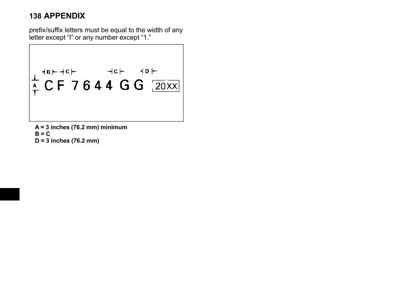
Black plate (138,1)
prefix/suffix letters must be equal to the width of anyletter except “I” or any number except “1.”
A = 3 inches (76.2 mm) minimumB = CD = 3 inches (76.2 mm)
138 APPENDIX
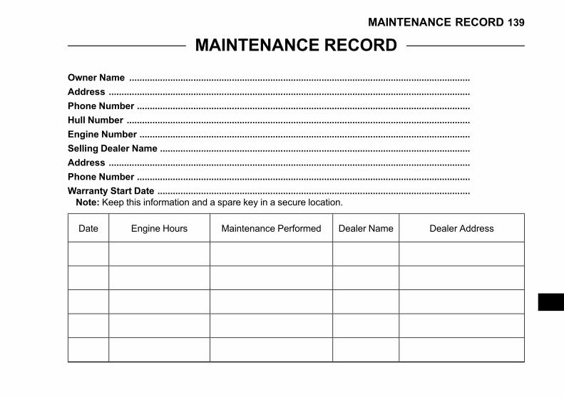
Black plate (139,1)
MAINTENANCE RECORD
Owner Name .....................................................................................................................................
Address .............................................................................................................................................
Phone Number ..................................................................................................................................
Hull Number ......................................................................................................................................
Engine Number .................................................................................................................................
Selling Dealer Name .........................................................................................................................
Address .............................................................................................................................................
Phone Number ..................................................................................................................................
Warranty Start Date ..........................................................................................................................Note: Keep this information and a spare key in a secure location.
Date Engine Hours Maintenance Performed Dealer Name Dealer Address
MAINTENANCE RECORD 139
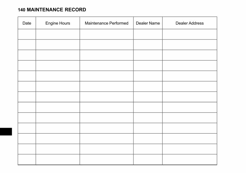
Black plate (140,1)
Date Engine Hours Maintenance Performed Dealer Name Dealer Address
140 MAINTENANCE RECORD

Black plate (141,1)
Date Engine Hours Maintenance Performed Dealer Name Dealer Address
MAINTENANCE RECORD 141

Black plate (142,1)
Date Engine Hours Maintenance Performed Dealer Name Dealer Address
142 MAINTENANCE RECORD

Black plate (143,1)
Date Engine Hours Maintenance Performed Dealer Name Dealer Address
MAINTENANCE RECORD 143