Embed Size (px)
Citation preview
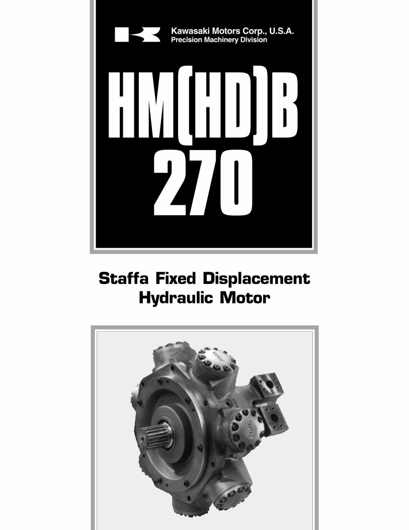
Staffa Fixed DisplacementHydraulic Motor
HM(HD)B270
Kawasaki Motors Corp., U.S.A.Precision Machinery Division
2
CONTENTS Page
1. General Description ............................... 2
2. Functional Symbols ............................... 2
3. Model Code ................................................ 3
4. Performance Data:Motor data ................................................... 4Rating definitions .................................... 4Output torques .......................................... 4Bearing life ........................................ 5 & 6Volumetric efficiency ............................. 7
5. Circuit and Application Notes:Starting torques ....................................... 7Low speed operation ............................ 7High back pressure ............................... 7Boost pressure ......................................... 7Cooling flow ............................................... 7Motor casing pressure ......................... 8
6. Hydraulic Fluids ....................................... 8
7. Temperature Limits ................................ 8
8. Filtration ........................................................ 8
9. Noise Levels ............................................... 8
10. Polar Moment of Inertia ....................... 8
11. Mass ................................................................ 8
12. Installation Data:General .......................................................... 8Crankcase drain ....................................... 8Start-up ......................................................... 8
13. Installation Dimensions .......... 9 to 12
1. GENERAL DESCRIPTIONThe HM(HD)B270 fixed displacementmotor is one of 12 frame sizes in theKawasaki “Staffa” range of high torque,low speed radial piston motors whichextends from 94 to 6800 cm3/r (5.76 to415 in3/r) capacity. The rugged, well-proven design incorporates hydrostaticbalancing techniques to achieve highefficiency, combined with good breakouttorque and smooth running capability.
This motor is available with standard orwith heavy duty shaft bearings, modeltypes HMB270 and HMHDB270respectively. Various features andoptions are available including, onrequest, mountings to match competitorinterfaces.
The HMHDB270 is capable of torqueoutputs up to 18 700 Nm (13 800 lbf ft)and speeds to 125 r/min with acontinuous output of up to 140 kW(188 hp).
The Kawasaki “Staffa” range alsoincludes dual and continuously variabledisplacement motors, plus matchingbrakes and gearboxes to extend theavailable torque range.
–SO4- -F4--FM4-
2. FUNCTIONAL SYMBOLSAll model types with variants in model code position 4
3
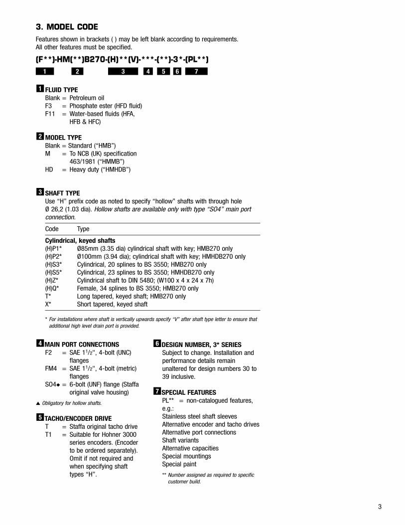
3. MODEL CODEFeatures shown in brackets ( ) may be left blank according to requirements. All other features must be specified.
(F**)-HM(**)B270-(H)**(V)-***-(**)-3*-(PL**)
FLUID TYPEBlank = Petroleum oilF3 = Phosphate ester (HFD fluid)F11 = Water-based fluids (HFA,
HFB & HFC)
MODEL TYPEBlank = Standard (“HMB”)M = To NCB (UK) specification
463/1981 (“HMMB”)HD = Heavy duty (“HMHDB”)
2
1
SHAFT TYPEUse “H” prefix code as noted to specify “hollow” shafts with through hole Ø 26,2 (1.03 dia). Hollow shafts are available only with type “SO4” main port connection.
Code Type
Cylindrical, keyed shafts(H)P1* Ø85mm (3.35 dia) cylindrical shaft with key; HMB270 only(H)P2* Ø100mm (3.94 dia); cylindrical shaft with key; HMHDB270 only(H)S3* Cylindrical, 20 splines to BS 3550; HMB270 only(H)S5* Cylindrical, 23 splines to BS 3550; HMHDB270 only(H)Z* Cylindrical shaft to DIN 5480; (W100 x 4 x 24 x 7h)(H)Q* Female, 34 splines to BS 3550; HMB270 onlyT* Long tapered, keyed shaft; HMB270 onlyX* Short tapered, keyed shaft
* For installations where shaft is vertically upwards specify “V” after shaft type letter to ensure thatadditional high level drain port is provided.
3
1 2 3 4 5 6 7
MAIN PORT CONNECTIONSF2 = SAE 11/2", 4-bolt (UNC)
flangesFM4 = SAE 11/2", 4-bolt (metric)
flangesSO4◆ = 6-bolt (UNF) flange (Staffa
original valve housing)
▲ Obligatory for hollow shafts.
TACHO/ENCODER DRIVET = Staffa original tacho driveT1 = Suitable for Hohner 3000
series encoders. (Encoderto be ordered separately).Omit if not required andwhen specifying shafttypes “H”.
5
4 DESIGN NUMBER, 3* SERIESSubject to change. Installation andperformance details remainunaltered for design numbers 30 to39 inclusive.
SPECIAL FEATURESPL** = non-catalogued features,e.g.:Stainless steel shaft sleevesAlternative encoder and tacho drivesAlternative port connectionsShaft variantsAlternative capacitiesSpecial mountingsSpecial paint
** Number assigned as required to specificcustomer build.
7
6
4
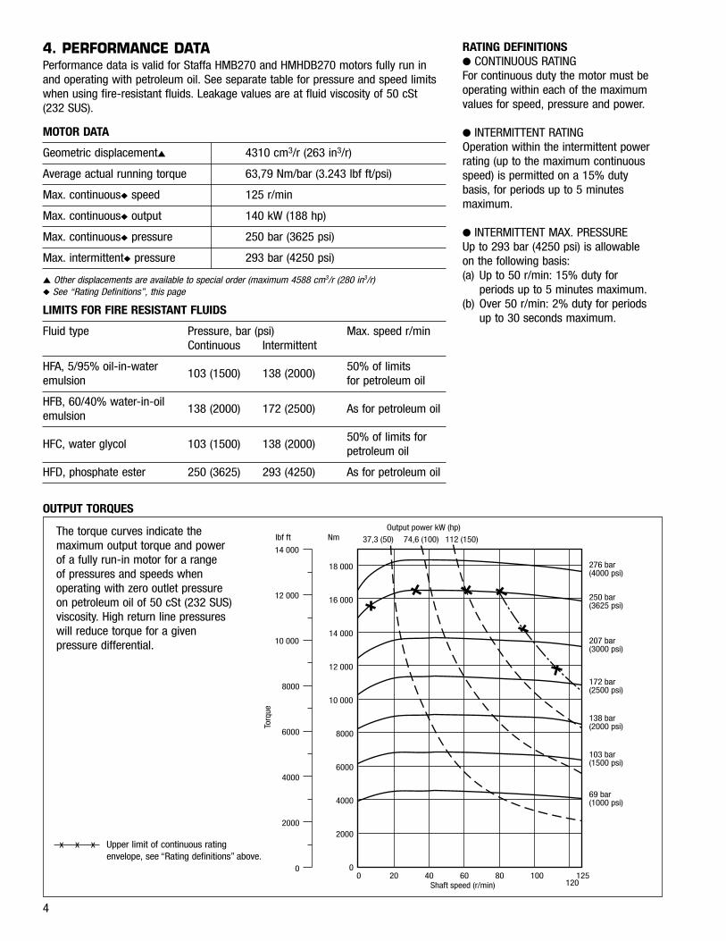
4. PERFORMANCE DATAPerformance data is valid for Staffa HMB270 and HMHDB270 motors fully run inand operating with petroleum oil. See separate table for pressure and speed limitswhen using fire-resistant fluids. Leakage values are at fluid viscosity of 50 cSt(232 SUS).
MOTOR DATA
Geometric displacement▲ 4310 cm3/r (263 in3/r)
Average actual running torque 63,79 Nm/bar (3.243 lbf ft/psi)
Max. continuous◆ speed 125 r/min
Max. continuous◆ output 140 kW (188 hp)
Max. continuous◆ pressure 250 bar (3625 psi)
Max. intermittent◆ pressure 293 bar (4250 psi)
▲ Other displacements are available to special order (maximum 4588 cm3/r (280 in3/r)◆ See “Rating Definitions”, this page
LIMITS FOR FIRE RESISTANT FLUIDS
Fluid type Pressure, bar (psi) Max. speed r/minContinuous Intermittent
HFA, 5/95% oil-in-water 50% of limits emulsion
103 (1500) 138 (2000)for petroleum oil
HFB, 60/40% water-in-oil emulsion
138 (2000) 172 (2500) As for petroleum oil
HFC, water glycol 103 (1500) 138 (2000)50% of limits for petroleum oil
HFD, phosphate ester 250 (3625) 293 (4250) As for petroleum oil
Output power kW (hp)
37,3 (50) 74,6 (100) 112 (150)lbf ft Nm
Torq
ue
14 000
12 000
10 000
8000
6000
4000
2000
0
18 000
16 000
14 000
12 000
10 000
8000
6000
4000
2000
0
276 bar(4000 psi)
250 bar(3625 psi)
207 bar(3000 psi)
172 bar(2500 psi)
138 bar(2000 psi)
103 bar(1500 psi)
69 bar(1000 psi)
0 20 40 60 80 100120
125Shaft speed (r/min)
OUTPUT TORQUES
RATING DEFINITIONS● CONTINUOUS RATINGFor continuous duty the motor must beoperating within each of the maximumvalues for speed, pressure and power.
● INTERMITTENT RATINGOperation within the intermittent powerrating (up to the maximum continuousspeed) is permitted on a 15% dutybasis, for periods up to 5 minutesmaximum.
● INTERMITTENT MAX. PRESSUREUp to 293 bar (4250 psi) is allowable on the following basis:(a) Up to 50 r/min: 15% duty for
periods up to 5 minutes maximum.(b) Over 50 r/min: 2% duty for periods
up to 30 seconds maximum.
The torque curves indicate themaximum output torque and powerof a fully run-in motor for a range of pressures and speeds whenoperating with zero outlet pressureon petroleum oil of 50 cSt (232 SUS)viscosity. High return line pressureswill reduce torque for a givenpressure differential.
x x x Upper limit of continuous ratingenvelope, see “Rating definitions” above.
Lmedian 150 000 50 000 30 20 10 000 4100 000 40 15 5000 3000
(d)
(c)
(h)
(i)
N = 25
N = 50
N = 75
N = 10
0
N = 12
5
(b)
(a)
(g)
P = 250 bar (3600 psi)
P = 207 bar (3000 psi)
P = 138 bar (2000 psi)
P = 70 bar (1000 psi)
A = 200 mm (8")A = 150 mm (6")A = 100 mm (4")
A = 50 mm (2")
Shaft stress limit
kN
20
40
60
80
(e)
(f)
lbf
5000
10 000
15 000
W
5
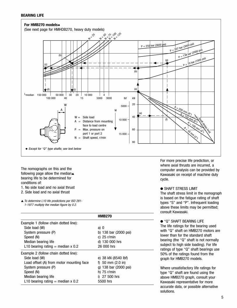
BEARING LIFE
For HMB270 models◆
(See next page for HMHDB270, heavy duty models)
The nomographs on this and thefollowing page allow the median▲
bearing life to be determined forconditions of:1. No side load and no axial thrust2. Side load and no axial thrust
▲ To determine L10 life predictions per ISO 281-1-1977 multiply the median figure by 0.2.
HMB270
Example 1 (follow chain dotted line):Side load (W) a) 0System pressure (P) b) 138 bar (2000 psi)Speed (N) c) 25 r/minMedian bearing life d) 130 000 hrsL10 bearing rating = median x 0.2 26 000 hrs
Example 2 (follow chain dotted line):Side load (W) e) 38 kN (8540 lbf)Load offset (A) from motor mounting face f) 50 mm (2.0 in)System pressure (P) g) 138 bar (2000 psi)Speed (N) h) 75 r/minMedian bearing life i) 27 500 hrsL10 bearing rating = median x 0.2 5500 hrs
For more precise life prediction, orwhere axial thrusts are incurred, acomputer analysis can be provided byKawasaki on receipt of machine dutycycle.
● SHAFT STRESS LIMITThe shaft stress limit in the nomographis based on the fatigue rating of shafttypes “S” and “P”. Infrequent loadingabove these limits may be permitted;consult Kawasaki.
● “Q” SHAFT BEARING LIFEThe life ratings for the bearing usedwith “Q” shaft on HMB270 motors arelower than for the standard shaftbearing (the “Q” shaft is not normallysubject to high side loading). For liferatings of type “Q” shaft bearings use50% of the ratings found from thegraph for HMB270 models.
Where unsatisfactory life ratings fortype “Q” shaft are found using theabove HMB270 graph, consult yourKawasaki representative for moreaccurate data, or possible alternativesolutions.
W = Side loadA = Distance from mounting
face to load centreP = Max. pressure on
port 1 or port 2N = Shaft speed, r/min
A
W
◆ Except for “Q” type shafts; see text below
6
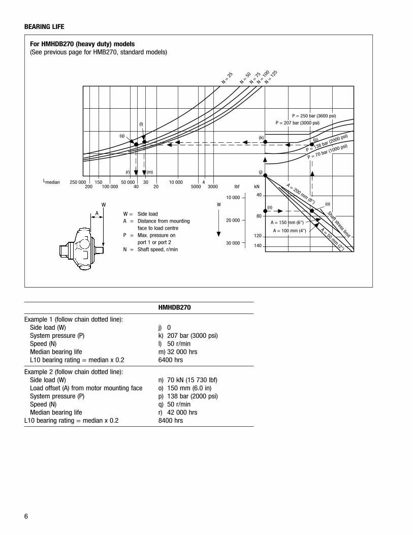
BEARING LIFE
For HMHDB270 (heavy duty) models(See previous page for HMB270, standard models)
HMHDB270
Example 1 (follow chain dotted line):Side load (W) j) 0System pressure (P) k) 207 bar (3000 psi)Speed (N) l) 50 r/minMedian bearing life m) 32 000 hrsL10 bearing rating = median x 0.2 6400 hrs
Example 2 (follow chain dotted line):Side load (W) n) 70 kN (15 730 lbf)Load offset (A) from motor mounting face o) 150 mm (6.0 in)System pressure (P) p) 138 bar (2000 psi)Speed (N) q) 50 r/minMedian bearing life r) 42 000 hrs
L10 bearing rating = median x 0.2 8400 hrs
(q)
(l)
(r) (m) (j)
(k)
Lmedian 250 000 150 50 000 30 10 000 4200 100 000 40 20 5000 3000 lbf kN
40
80
120
140
10 000
20 000
30 000
W(n)
(o)
A = 150 mm (6")
A = 100 mm (4")
A = 200 mm (8")
A = 50 mm (2")
Shaft stress limit
P = 70 bar (1000 psi)P = 138 bar (2000 psi)
(p)
P = 250 bar (3600 psi)
P = 207 bar (3000 psi)
N = 2
5
N = 5
0N =
75
N = 1
00N =
125
W = Side loadA = Distance from mounting
face to load centreP = Max. pressure on
port 1 or port 2N = Shaft speed, r/min
A
W
7
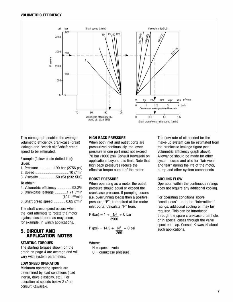
This nomograph enables the averagevolumetric efficiency, crankcase (drain)leakage and “winch slip”/shaft creepspeed to be estimated.
Example (follow chain dotted line):Given:1. Pressure .....................190 bar (2756 psi)2. Speed ..................................................10 r/min3. Viscosity .........................50 cSt (232 SUS)
To obtain:4. Volumetric efficiency ......................92.2%5. Crankcase leakage .................1,71 l/min
(104 in3/min)6. Shaft creep speed ..................0.65 r/min
The shaft creep speed occurs when the load attempts to rotate the motoragainst closed ports as may occur, for example, in winch applications.
5. CIRCUIT ANDAPPLICATION NOTES
STARTING TORQUESThe starting torques shown on thegraph on page 4 are average and willvary with system parameters.
LOW SPEED OPERATIONMinimum operating speeds aredetermined by load conditions (loadinertia, drive elasticity, etc.). Foroperation at speeds below 2 r/minconsult Kawasaki.
HIGH BACK PRESSUREWhen both inlet and outlet ports arepressurized continuously, the lowerpressure in one port must not exceed70 bar (1000 psi). Consult Kawasaki onapplications beyond this limit. Note thathigh back pressures reduce theeffective torque output of the motor.
BOOST PRESSUREWhen operating as a motor the outletpressure should equal or exceed thecrankcase pressure. If pumping occurs(i.e. overrunning loads) then a positivepressure, “P”, is required at the motorinlet ports. Calculate “P” from:
P (bar) = 1 + N2 + C bar3900
P (psi) = 14.5 + N2 + C psi269
Where:N = speed, r/minC = crankcase pressure
The flow rate of oil needed for themake-up system can be estimated fromthe crankcase leakage figure (seeVolumetric Efficiency graph above).Allowance should be made for othersystem losses and also for “fair wearand tear” during the life of the motor,pump and other system components.
COOLING FLOWOperation within the continuous ratingsdoes not require any additional cooling.
For operating conditions above“continuous”, up to the “intermittent”ratings, additional cooling oil may berequired. This can be introducedthrough the spare crankcase drain hole,or in special cases through the valvespool end cap. Consult Kawasaki aboutsuch applications.
VOLUMETRIC EFFICIENCY
0
Pres
sure
1000
2000
3000
4000
psi bar Shaft speed (r/min)
2
5
10 25 50 125
70 80 90 100
Volumetric efficiency (%)At 50 cSt (232 SUS)
300
200
100
0
200
(960
)
100
(465
)
50 (2
32)
25 (1
19)
Shaft creep/winch-slip speed (r/min)
0 0.5 1.0 1.5
0
0 50 100 150 200 250 in3/min
1 2 3 4Crankcase leakage/drain flow rate
l/min
Viscosity cSt (SUS)
8
MOTOR CASING PRESSUREWith the standard shaft seal fitted, themotor casing pressure should notexceed 3,5 bar (50 psi). On installationswith long drain lines a relief valve isrecommended to prevent over-pressurizing the seal.
Notes:1. The casing pressure at all times must not
exceed either the motor inlet or outlet pressure.2. High pressure shaft seals are available to
special order for casing pressures of:Continuous: 10 bar (150 psi)Intermittent: 15 bar (225 psi)
3. Check installation dimensions (page 9) formaximum crankcase drain fitting depth.
6. HYDRAULIC FLUIDSDependent on motor (see Model Codeposition ) suitable fluids include:- Antiwear hydraulic oils- Phosphate esters (HFD fluids)- Water glycols (HFC fluids) ▲- 60/40% water-in-oil emulsions
(HFB fluids) ▲- 5/95% oil-in-water emulsions
(HFA fluids) ▲
▲ Reduced pressure and speed limits, see page 4.
Viscosity limits when using any fluidexcept oil-in-water (5/95%) emulsionsare:Max. off load ............2000 cSt (9270 SUS)Max. on load ..................150 cSt (695 SUS)Optimum ..............................50 cSt (232 SUS)Minimum .............................25 cSt (119 SUS)
PETROLEUM OIL RECOMMENDATIONSThe fluid should be a good hydraulicgrade, non-detergent petroleum oil. Itshould contain anti-oxidant, anti-foamand demulsifying additives. It mustcontain antiwear or EP additives.Automatic transmission fluids and motoroils are not recommended.
7. TEMPERATURE LIMITSAmbient min...............................-30°C (-22°F)Ambient max............................+70°C (158°F)
Max. operating temperature range
Petroleum Wateroil containing
Min. -20°C (-4°F) +10°C (50°F)
Max.* +80°C (175°F) +54°C (130°F)
* To obtain optimum service life from both fluidand hydraulic system components 65°C(150°F) normally is the maximum temperatureexcept for water-containing fluids.
1
8. FILTRATIONFull flow filtration (open circuit), or fullboost flow filtration (closed circuit) toensure system cleanliness of ISO4406/1986 code 18/14 or cleaner.
9. NOISE LEVELSThe airborne noise level is less than66.7 dB(A) DIN (70 dB(A) NFPA)throughout the “continuous” operatingenvelope.
Where noise is a critical factor,installation resonances can be reducedby isolating the motor by elastomericmeans from the structure and thereturn line installation. Potential returnline resonances originating from liquidborne noise can be further attenuatedby providing a return line back pressureof 2 to 5 bar (30 to 70 psi).
10. POLAR MOMENT OFINERTIA
Typical data: 0,91 kg m2 (3100 lb in2)
11. MASSApprox., all models: 420 kg (925 lb)
12. INSTALLATION DATAGENERAL● SpigotThe motor should be located by themounting spigot on a flat, robustsurface using correctly sized bolts. Thediametral clearance between the motorspigot and the mounting must notexceed 0,15 mm (0.006 in). If theapplication incurs shock loading,frequent reversing or high speedrunning, then high tensile bolts shouldbe used, including one fitted bolt.
● Bolt torqueThe recommended torque wrenchsettings for the mounting bolts are:M20 bolts .......407±14Nm (300±10 lbf ft)3/4" bolts .........393±14Nm (290±10 lbf ft)
● Shaft couplingWhere the motor is solidly coupled to ashaft having independent bearings theshafts must be aligned to within 0,13mm (0.005 in) TIR.
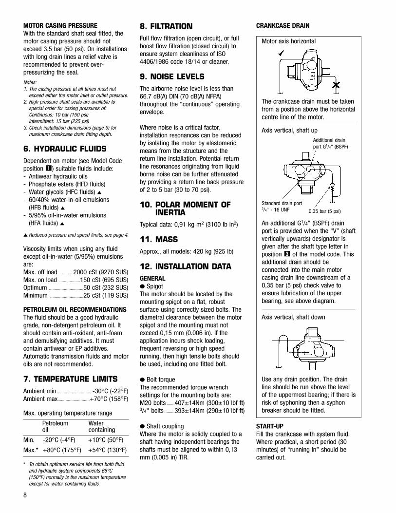
CRANKCASE DRAIN
Motor axis horizontal
The crankcase drain must be takenfrom a position above the horizontalcentre line of the motor.
Axis vertical, shaft up
Additional drainport G1/4" (BSPF)
0,35 bar (5 psi)
Standard drain port 3/4" - 16 UNF
An additional G1/4" (BSPF) drainport is provided when the “V” (shaftvertically upwards) designator isgiven after the shaft type letter inposition of the model code. Thisadditional drain should beconnected into the main motorcasing drain line downstream of a0,35 bar (5 psi) check valve toensure lubrication of the upperbearing, see above diagram.
3
Axis vertical, shaft down
Use any drain position. The drainline should be run above the levelof the uppermost bearing; if there isrisk of syphoning then a syphonbreaker should be fitted.
START-UPFill the crankcase with system fluid.Where practical, a short period (30minutes) of “running in” should becarried out.
9
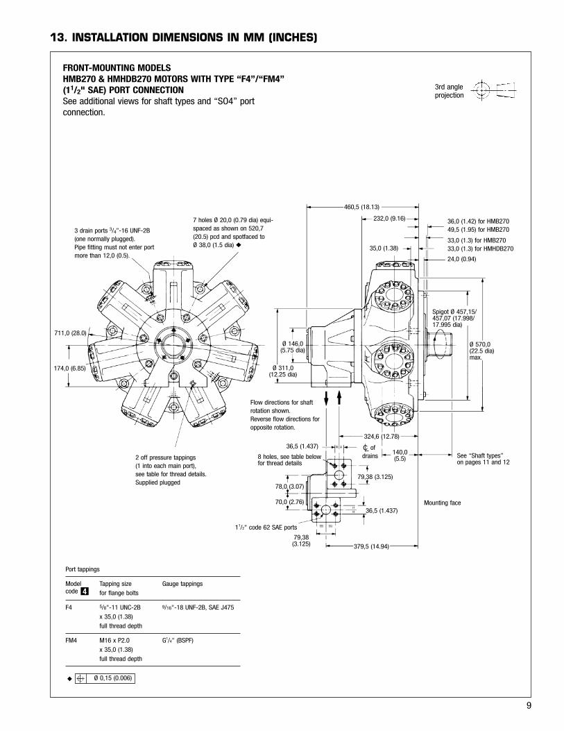
13. INSTALLATION DIMENSIONS IN MM (INCHES)
2 off pressure tappings(1 into each main port),see table for thread details.Supplied plugged
Flow directions for shaftrotation shown. Reverse flow directions foropposite rotation.
3 drain ports 3/4”-16 UNF-2B(one normally plugged).Pipe fitting must not enter portmore than 12,0 (0.5).
7 holes Ø 20,0 (0.79 dia) equi-spaced as shown on 520,7(20.5) pcd and spotfaced toØ 38,0 (1.5 dia) ◆
460,5 (18.13)
232,0 (9.16)
35,0 (1.38)
36,0 (1.42) for HMB27049,5 (1.95) for HMB270
33,0 (1.3) for HMB27033,0 (1.3) for HMHDB270
24,0 (0.94)
Ø 311,0 (12.25 dia)
Ø 146,0 (5.75 dia)
Spigot Ø 457,15/457,07 (17.998/17.995 dia)
Ø 570,0(22.5 dia)max.
See “Shaft types”on pages 11 and 12
Mounting face
140,0(5.5)
324,6 (12.78)
79,38 (3.125)
78,0 (3.07)
36,5 (1.437)
8 holes, see table belowfor thread details
70,0 (2.76)36,5 (1.437)
379,5 (14.94)79,38(3.125)
11/2" code 62 SAE ports
711,0 (28.0)
174,0 (6.85)
◆ Ø 0,15 (0.006)
3rd angleprojection
Port tappings
Model Tapping size Gauge tappingscode for flange bolts
F4 5/8"-11 UNC-2B 9/16"-18 UNF-2B, SAE J475x 35,0 (1.38) full thread depth
FM4 M16 x P2.0 G1/4" (BSPF)x 35,0 (1.38)full thread depth
4
FRONT-MOUNTING MODELSHMB270 & HMHDB270 MOTORS WITH TYPE “F4”/“FM4”(11/2" SAE) PORT CONNECTIONSee additional views for shaft types and “SO4” portconnection.
of drainsC
6-BOLT FLANGE, “SO4” IN MODEL CODE POSITION 4
▲ Ø 35,0 (1.325 dia), with recess for 38,1 (1.5) i/d x Ø 3,53 (0.139 dia)section O-ring
Ø 311,0 (12.25)
110,0(4.31)
Ø 146,0(5.75 dia)
86,0(3.37)
457,0 (18.0)
365,0 (14.4)157,0 (6.19)
50,8 (2.0)
11,0 (0.44)
76,0 (3.0)
r. 16,0 (0.625)
Port 2▲
Port 1▲
6 holes3/8" -24 UNF-2B,16,0 (0.62) deep
60,0
(2.375)
66,7
(2.625)
60,0
(2.375)
r.22,0(0.875)
79,0 (3.125)
Flow direction for shaftrotation shown on maindrawing on page 9.Reverse flow for opposite direction of shaft rotation.
Mounting face
10
11
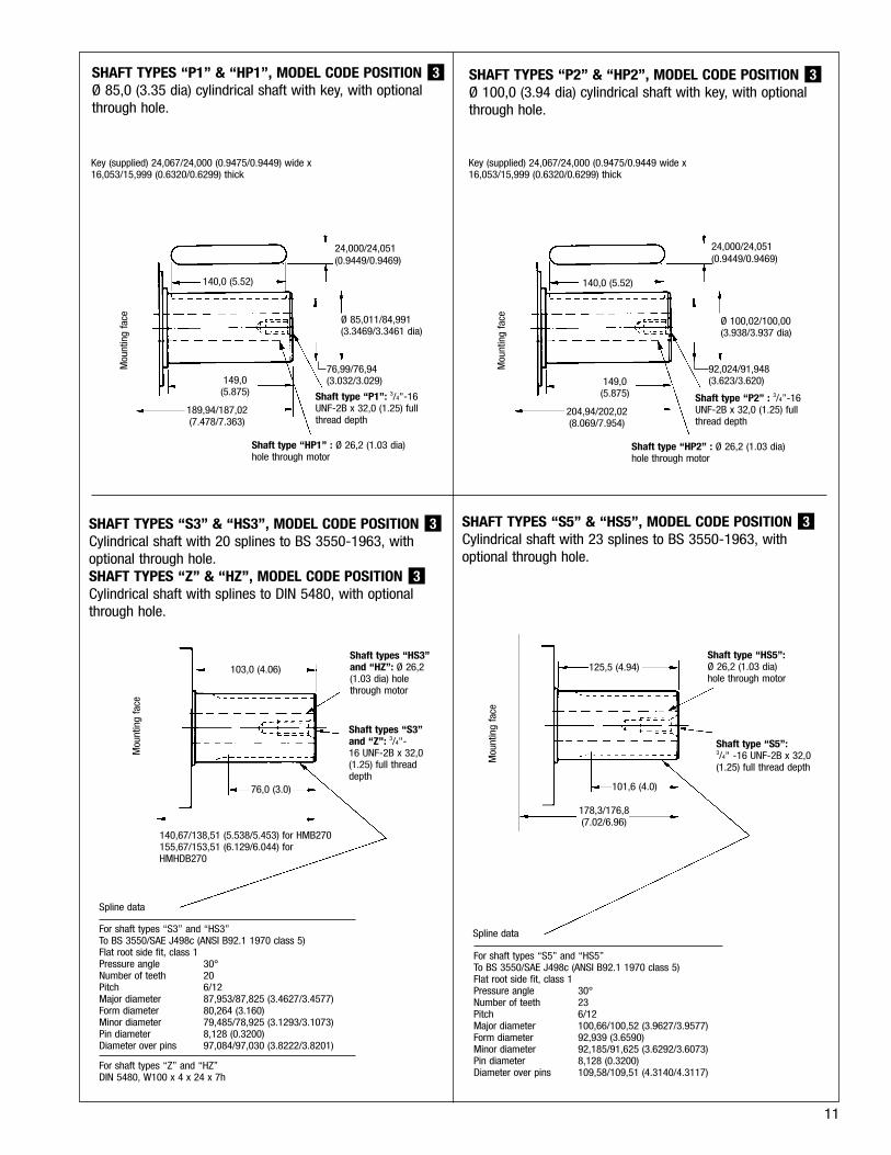
SHAFT TYPES “P1” & “HP1”, MODEL CODE POSITIONØ 85,0 (3.35 dia) cylindrical shaft with key, with optionalthrough hole.
3 SHAFT TYPES “P2” & “HP2”, MODEL CODE POSITIONØ 100,0 (3.94 dia) cylindrical shaft with key, with optionalthrough hole.
3
SHAFT TYPES “S3” & “HS3”, MODEL CODE POSITIONCylindrical shaft with 20 splines to BS 3550-1963, withoptional through hole.SHAFT TYPES “Z” & “HZ”, MODEL CODE POSITIONCylindrical shaft with splines to DIN 5480, with optionalthrough hole.
3
3 SHAFT TYPES “S5” & “HS5”, MODEL CODE POSITIONCylindrical shaft with 23 splines to BS 3550-1963, withoptional through hole.
3
103,0 (4.06)Shaft types “HS3”and “HZ”: Ø 26,2(1.03 dia) holethrough motor
Shaft types “S3”and “Z”: 3/4"-16 UNF-2B x 32,0(1.25) full threaddepth
76,0 (3.0)
140,67/138,51 (5.538/5.453) for HMB270155,67/153,51 (6.129/6.044) forHMHDB270
Spline data
Mou
ntin
g fa
ce
125,5 (4.94)Shaft type “HS5”:Ø 26,2 (1.03 dia)hole through motor
Shaft type “S5”:3/4" -16 UNF-2B x 32,0(1.25) full thread depth
101,6 (4.0)
178,3/176,8(7.02/6.96)
Spline data
Mou
ntin
g fa
ce
For shaft types “S5” and “HS5”To BS 3550/SAE J498c (ANSI B92.1 1970 class 5)Flat root side fit, class 1Pressure angle 30°Number of teeth 23Pitch 6/12Major diameter 100,66/100,52 (3.9627/3.9577)Form diameter 92,939 (3.6590)Minor diameter 92,185/91,625 (3.6292/3.6073)Pin diameter 8,128 (0.3200)Diameter over pins 109,58/109,51 (4.3140/4.3117)
For shaft types “S3” and “HS3”To BS 3550/SAE J498c (ANSI B92.1 1970 class 5)Flat root side fit, class 1Pressure angle 30°Number of teeth 20Pitch 6/12Major diameter 87,953/87,825 (3.4627/3.4577)Form diameter 80,264 (3.160)Minor diameter 79,485/78,925 (3.1293/3.1073)Pin diameter 8,128 (0.3200)Diameter over pins 97,084/97,030 (3.8222/3.8201)
For shaft types “Z” and “HZ”DIN 5480, W100 x 4 x 24 x 7h
24,000/24,051(0.9449/0.9469)
140,0 (5.52)
149,0(5.875)
189,94/187,02(7.478/7.363)
Mou
ntin
g fa
ce
Key (supplied) 24,067/24,000 (0.9475/0.9449) wide x16,053/15,999 (0.6320/0.6299) thick
Ø 85,011/84,991(3.3469/3.3461 dia)
76,99/76,94(3.032/3.029)
Shaft type “P1”: 3/4"-16UNF-2B x 32,0 (1.25) fullthread depth
Shaft type “HP1” : Ø 26,2 (1.03 dia)hole through motor
Key (supplied) 24,067/24,000 (0.9475/0.9449 wide x16,053/15,999 (0.6320/0.6299) thick
24,000/24,051(0.9449/0.9469)
140,0 (5.52)
149,0(5.875)
204,94/202,02(8.069/7.954)
Mou
ntin
g fa
ce Ø 100,02/100,00(3.938/3.937 dia)
92,024/91,948(3.623/3.620)
Shaft type “P2” : 3/4”-16UNF-2B x 32,0 (1.25) fullthread depth
Shaft type “HP2” : Ø 26,2 (1.03 dia)hole through motor
12
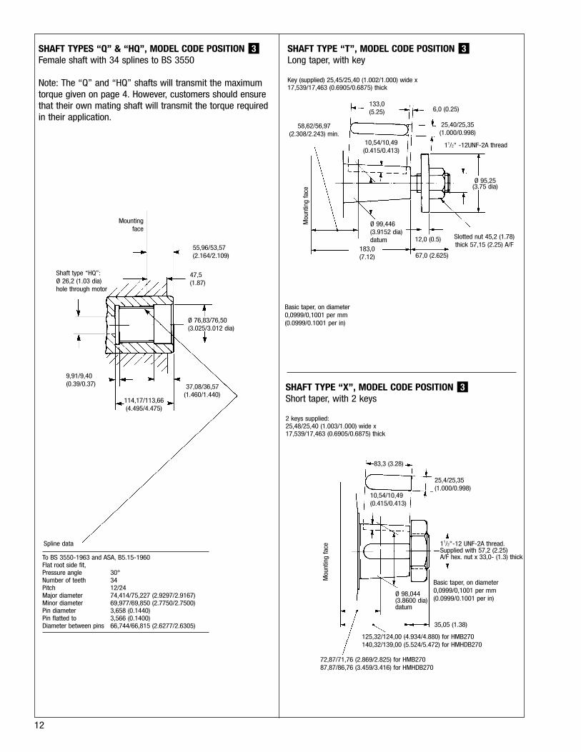
SHAFT TYPE “T”, MODEL CODE POSITIONLong taper, with key
Key (supplied) 25,45/25,40 (1.002/1.000) wide x17,539/17,463 (0.6905/0.6875) thick
3SHAFT TYPES “Q” & “HQ”, MODEL CODE POSITIONFemale shaft with 34 splines to BS 3550
Note: The “Q” and “HQ” shafts will transmit the maximumtorque given on page 4. However, customers should ensurethat their own mating shaft will transmit the torque requiredin their application.
3
SHAFT TYPE “X”, MODEL CODE POSITIONShort taper, with 2 keys
2 keys supplied:25,48/25,40 (1.003/1.000) wide x17,539/17,463 (0.6905/0.6875) thick
3
To BS 3550-1963 and ASA, B5.15-1960Flat root side fit, Pressure angle 30°Number of teeth 34Pitch 12/24Major diameter 74,414/75,227 (2.9297/2.9167)Minor diameter 69,977/69,850 (2.7750/2.7500)Pin diameter 3,658 (0.1440)Pin flatted to 3,566 (0.1400)Diameter between pins 66,744/66,815 (2.6277/2.6305)
Shaft type “HQ”:Ø 26,2 (1.03 dia)hole through motor
Mountingface
9,91/9,40(0.39/0.37)
Spline data
72,87/71,76 (2.869/2.825) for HMB27087,87/86,76 (3.459/3.416) for HMHDB270
125,32/124,00 (4.934/4.880) for HMB270140,32/139,00 (5.524/5.472) for HMHDB270
Basic taper, on diameter0,0999/0,1001 per mm(0.0999/0.1001 per in)
10,54/10,49(0.415/0.413)
83,3 (3.28)
25,4/25,35(1.000/0.998)
133,0 (5.25)
Mou
ntin
g fa
ce 11/2"-12 UNF-2A thread.Supplied with 57,2 (2.25)A/F hex. nut x 33,0- (1.3) thick
35,05 (1.38)
Ø 98,044(3.8600 dia)datum
114,17/113,66(4.495/4.475)
37,08/36,57(1.460/1.440)
Ø 76,83/76,50(3.025/3.012 dia)
55,96/53,57(2.164/2.109)
47,5(1.87)
6,0 (0.25)
25,40/25,35(1.000/0.998)
Ø 95,25(3.75 dia)
Slotted nut 45,2 (1.78)thick 57,15 (2.25) A/F
67,0 (2.625)
12,0 (0.5)
183,0 (7.12)
Ø 99,446(3.9152 dia)datum
10,54/10,49(0.415/0.413)
58,62/56,97(2.308/2.243) min.
Basic taper, on diameter0,0999/0,1001 per mm(0.0999/0.1001 per in)
Mou
ntin
g fa
ce
11/2" -12UNF-2A thread

NOTES
13

14
NOTES

15
NOTES
Presented by:
P-969-0020B A/GB1001 The right to modification for technical improvement is reserved. SG1M 2/00
Staffa hydraulic motors are manufactured to the highestquality standards in a KawasakiISO 9001 certified facility.Certification No. 891150