Embed Size (px)
Citation preview
i
KAUNAS UNIVERSITY OF TECHNOLOGY
MECHANICAL ENGINEERING AND DESIGN FACULTY
Gnanabharathi Ganesan
STRENGTH ANALYSIS OF SCISSOR LIFT DEVELOPED
FOR HOUSEHOLD APPLICATIONS
Master’s Degree Final Project
Supervisor
Assoc. prof. dr. Audrius Jutas.
KAUNAS, 2017
ii
KAUNAS UNIVERSITY OF TECHNOLOGY
MECHANICAL ENGINEERING AND DESIGN FACULTY
STRENGTH ANALYSIS OF SCISSOR LIFT DEVELOPED
FOR HOUSEHOLD APPLICATIONS
Master’s Degree Final Project
MASTERS IN MECHANICAL ENGINEERING
Supervisor
Assoc. prof. dr. Audrius Jutas
Reviewer
Assoc. prof. dr. Vitalis Leisis
Project made by
Gnanabharathi Ganesan
iii
KAUNAS UNIVERSITY OF TECHNOLOGY
MECHANICAL ENGINEERING AND DESIGN
(Faculty)
GNANABHARATHI GANESAN
(Student's name, surname)
MASTERS IN MECHANICAL ENGINEERING, 621H30001
(Title and code of study programme, code)
"STRENGTH ANALYSIS OF SCISSOR LIFT DEVELOPED
FOR HOUSEHOLD APPLICATIONS"
DECLARATION OF ACADEMIC INTEGRITY
June 2017
Kaunas
I confirm that the final project of mine, Gnanabharathi Ganesan, on the subject
“Strength analysis of scissor lift developed for household applications” is written completely
by myself; all the provided data and research results are correct and have been obtained
honestly. None of the parts of this thesis have been plagiarized from any printed, Internet-based
or otherwise recorded sources. All direct and indirect quotations from external resources are
indicated in the list of references. No monetary funds (unless required by law) have been paid
to anyone for any contribution to this thesis.
I fully and completely understand that any discovery of any manifestations/case/facts of
dishonesty inevitably results in me incurring a penalty according to the procedure(s) effective
at Kaunas University of Technology.
(name and surname filled in by hand) (signature)
iv
KAUNAS UNIVERSITY OF TECHNOLOGY
FACULTY OF MECHANICAL ENGINEERING AND DESIGN
Approved:
Head of Mechanical Engineering Department
(Signature, date)
Vytautas Grigas
(Name, Surname)
Head of Study Programmes in the Field of Mechanical Engineering
(Signature, date)
Kęstutis Pilkauskas
(Name, Surname)
MASTER STUDIES FINAL PROJECT TASK ASSIGNMENT
STUDY PROGRAMME MECHANICAL ENGINERING - 621H30001
Approved by the Dean’s Order No. V25-11-8 of April 21, 2017 y Assigned to the student Gnanabharathi Ganesan ___________________________________________________________________________
(Name, Surname)
1. Title of the Project
2. Aim of the project
3. Tasks of the project
Strength analysis of scissor lift developed for household applications.
The aim of the project is to design and strength analysis of the scissor lift that is elevated by the
mechanical drive (leadscrew and bevel gear) for household application.
Operational modelling according to different conditions of expectation.
Stress analysis of the structural elements consisting frame.
To adopt mechanical drive for the scissor lift
v
4. Specific Requirements
5. This task assignment is an integral part of the final project
6. Project submission deadline: 2017 May 19th
________________________________________________________________________________
Task Assignment received Gnanabharathi Ganesan _____________________ (Name, Surname of the Student) (Signature, date)
Supervisor Assoc. prof. dr. Audrius Jutas ____________________ (Position, Name, Surname) (Signature, date)
The device is limited to a mean load of 300Kilograms.
vi
Gnanabharathi Ganesan. Strength analysis of scissor lift developed for household applications.
Masters in Mechanical Engineering Supervisor Assoc. prof. dr. Audrius Jutas; Kaunas University of
Technology, Mechanical Engineering faculty, Mechanical Engineering department.
Kaunas, 2017. 63 p.
Summary
In this research proposal, an attempt is made to strength evaluation according to stress
analysis of scissor lift developed for household application. Conventionally a scissor lift or
jack is used for lifting a person's, medium weight things to appreciable height and it will be
used for numerous functions like maintenance and lots of material handling operations. We
can find the scissor lift by mechanical, pneumatic or hydraulic kind. But in this project it's
targeted to develop the scissor lift by exploitation of the mechanical drive (leadscrew, bevel
gear) that is fitted upper plate of the lift to control the consumer throughout its exportation,
when he is on the upper panel of the lift. But the design delineate within the paper is
developed keeping in mind that the lift operated by mechanical drive with the above
mentioned condition suggests that, so that the price of the lift is reduced. Also such design
will build the lift’s additional compact and a much more suitable for household application.
To achieve this project objective, I followed the project design methodology from theoretical
calculations, design had been done by exploitation SolidWorks 2014 package and analysis
had been done by ANSYS R14.5 package.
KEY WORDS: scissor lift, mechanical drive, stress, simulation.
vii
Gnanabharathi Ganesan. Namų ūkiams skirto žirklinio keltuvo stiprumo analizė.
Magistratūros studijų baigiamojo darbo vadovas doc. Audrius Jutas.
Kauno technologijos Universitetas, Mechanikos inžinerijos ir dizaino fakultetas,
Inžinerinės mechanikos katedra.
Kaunas, 2017. 63 p.
Santrauka
Šiame tyrime sprendžiami keltuvo, skirto namų ūkiams, stiprumo klausimai, pasitelkent įtempių
analizę.
Šis keltuvas yra skirtas kelti žmones ar daiktus į pasirinktą aukštį bei suteikia galimybę atlikti
tam tikrus ūkio darbus. Tarp dažniausiai naudojamų keltuvų yra mechaniniai, pneumatiniai ir
hidrauliniai keltuvai. Šiuo darbu siekiama ištobulinti keltuvą su mechanine pavara (kūginiai
krumpliaračiais), kuri yra sumontuota judančioje keltuvo platformoje ir gali būti valdoma
naudotojo stovinčiam ant jos. Šio keltuvo dizainui būtina įtempių analizė, kuriais siekiama
sukurti patrauklios kainos gaminį. Kita vertus, toks keltuvas turi būti kompaktiškas ir nesunkiai
transportuojamas. Kad būtų įgyvendinti iškelti tikslai, keltuvo dizainas buvo kuriamas
naudojantis programiniu paketu SolidWorks 2014, o įtempių analizei buvo naudojamasi
analitinėmis įtempių būvio formulėmis ir programiniu paketu ANSYS R14.5.
RAKTINIAI ŽODŽIAI: žirklinis keltuvas, mechaninė pavara, įtempiai, modeliavimas.
viii
Table of Contents
1. Introduction ........................................................................................................................ 1
1.1 Project Background ..................................................................................................... 1
1.2 Project problem Statement .......................................................................................... 2
1.3 Scope of the study ....................................................................................................... 3
1.4 Project objective .......................................................................................................... 3
1.5 Project importance....................................................................................................... 3
2. Analysis of existing approaches......................................................................................... 4
2.1 Medium duty scissor lifts available in market ............................................................ 4
2.2 Literature Review ........................................................................................................ 7
2.3 Conclusion ................................................................................................................. 11
3. Design calculations for scissor lift components ............................................................... 12
3.1 Design of scissor legs (link) ...................................................................................... 12
3.1.1 Normal force, shear force and bending moment ................................................ 14
3.1.2 Normal stress due to normal force and bending ................................................ 16
3.1.3 Bending Moment of the rectangular hollow section link .................................. 18
3.1.4 Stresses in a link bidirectional ........................................................................... 22
3.1.5 Euler Equation ................................................................................................... 24
3.1.6 Stress analysis due to complex loading ............................................................. 27
3.2 Design of base plate .................................................................................................. 30
3.3 Design of upper plate ................................................................................................ 30
3.4 Design of leadscrew .................................................................................................. 32
3.5 Design of Bevel gear ................................................................................................. 33
3.6 Design of Ball Bearing .............................................................................................. 35
3.7 Bolt & Nut calculation .............................................................................................. 37
3.8 Ratchet and Pawl ....................................................................................................... 37
ix
3.9 Castor Wheel ............................................................................................................. 39
3.10 Final Design of the scissor lift ............................................................................... 40
3.11 Working Principle ......................................................................................................... 41
4. Simulation Procedure ....................................................................................................... 42
4.1 Analysis details ......................................................................................................... 42
4.2 Loading condition ..................................................................................................... 43
4.3 Mesh formation ......................................................................................................... 44
4.3.1 Meshing Details ................................................................................................. 45
4.4 Properties of the Materials ........................................................................................ 46
4.5 Results ....................................................................................................................... 47
4.5.1 Analysis of link Total Deformation ................................................................... 47
4.5.2 Equivalent von-mises Stress .............................................................................. 47
4.5.3 Equivalent Elastic Strain .................................................................................... 48
4.6 Analysis of Bolt ......................................................................................................... 48
4.6.1 Total Deformation .............................................................................................. 48
4.6.2 Equivalent Elastic Stress .................................................................................... 49
4.6.3 Equivalent Elastic Strain .................................................................................... 49
4.7 Analysis of Nut.......................................................................................................... 50
4.7.1 Total deformation............................................................................................... 50
4.7.2 Equivalent Elastic Stress .................................................................................... 50
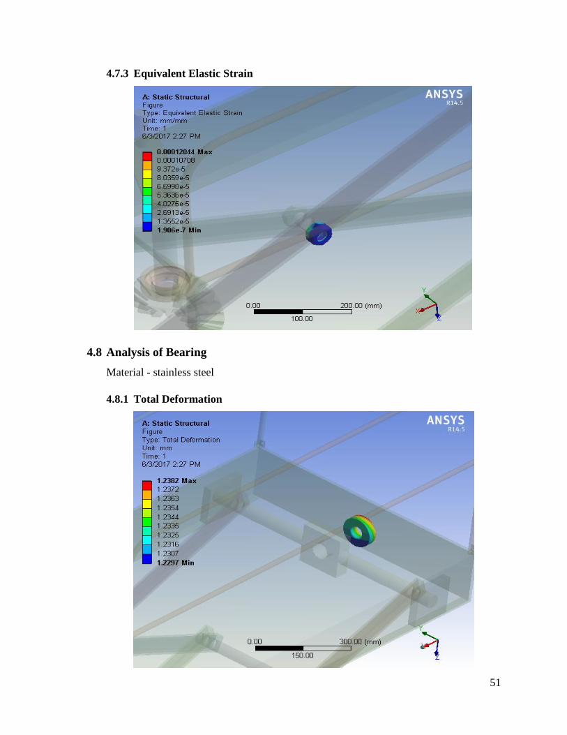
4.7.3 Equivalent Elastic Strain .................................................................................... 51
4.8 Analysis of Bearing ................................................................................................... 51
4.8.1 Total Deformation .............................................................................................. 51
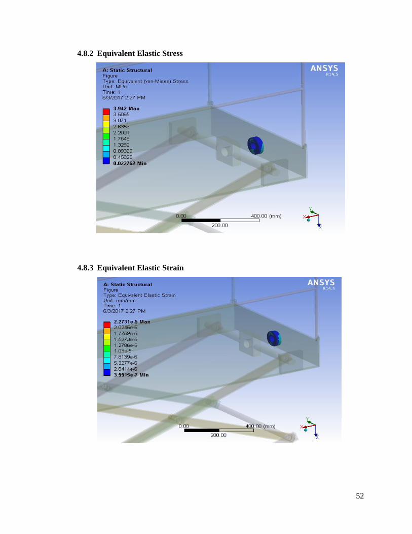
4.8.2 Equivalent Elastic Stress .................................................................................... 52
4.8.3 Equivalent Elastic Strain .................................................................................... 52
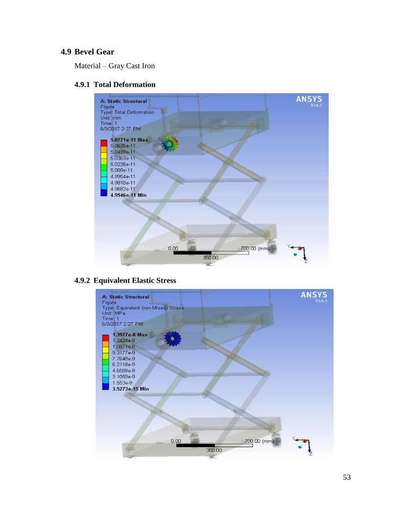
4.9 Bevel Gear ................................................................................................................. 53
4.9.1 Total Deformation .............................................................................................. 53

x
4.9.2 Equivalent Elastic Stress .................................................................................... 53
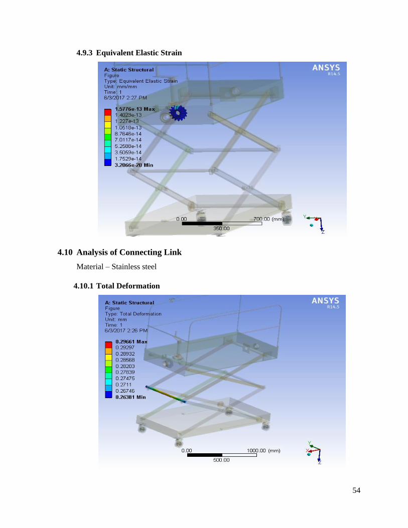
4.9.3 Equivalent Elastic Strain .................................................................................... 54
4.10 Analysis of Connecting Link ................................................................................. 54
4.10.1 Total Deformation .............................................................................................. 54
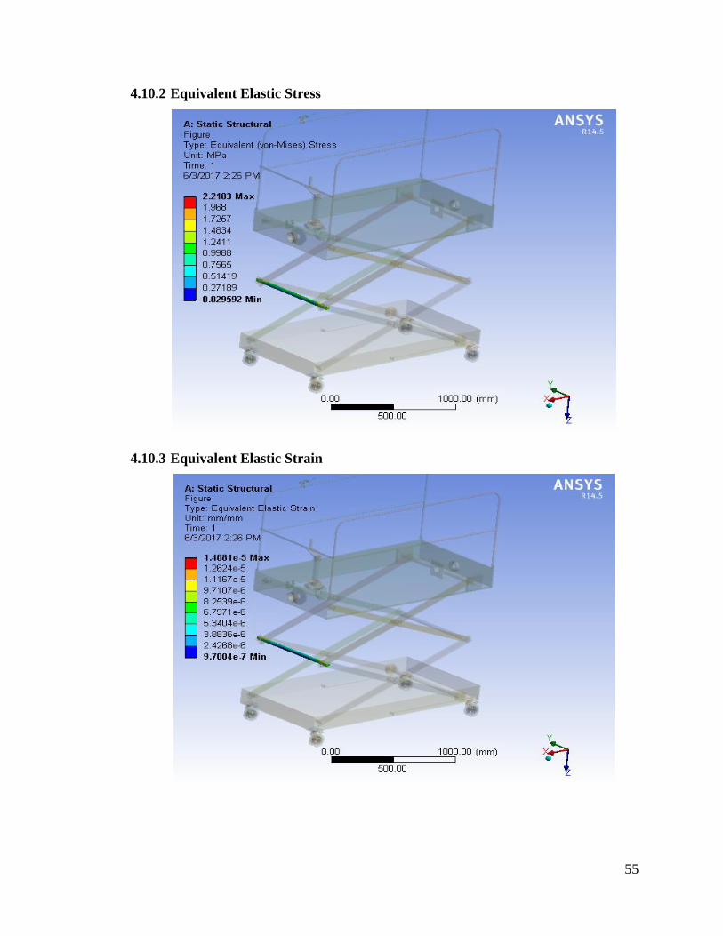
4.10.2 Equivalent Elastic Stress .................................................................................... 55
4.10.3 Equivalent Elastic Strain .................................................................................... 55
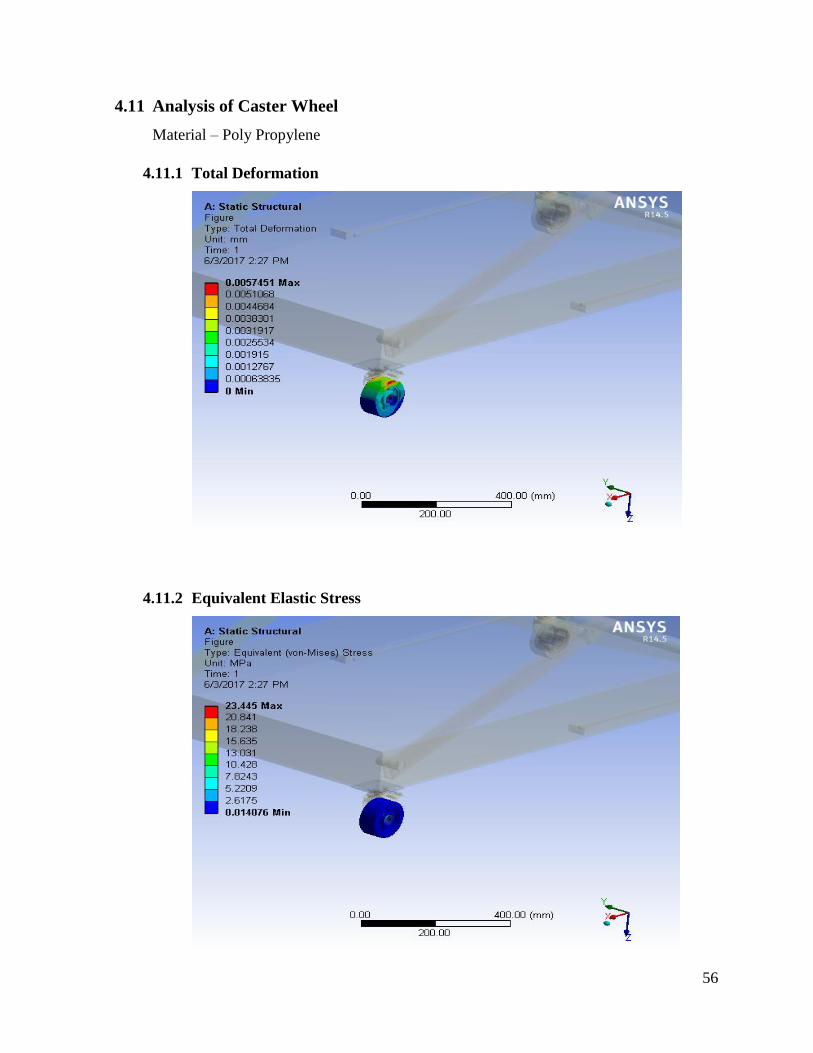
4.11 Analysis of Caster Wheel ...................................................................................... 56
4.11.1 Total Deformation .............................................................................................. 56
4.11.2 Equivalent Elastic Stress .................................................................................... 56
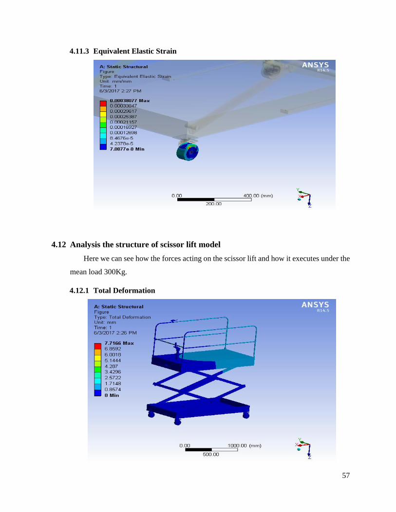
4.11.3 Equivalent Elastic Strain .................................................................................... 57
4.12 Analysis the structure of scissor lift model ........................................................... 57
4.12.1 Total Deformation .............................................................................................. 57
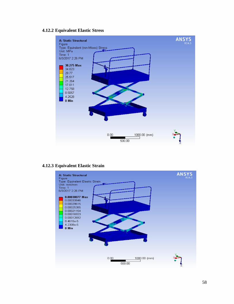
4.12.2 Equivalent Elastic Stress .................................................................................... 58
4.12.3 Equivalent Elastic Strain .................................................................................... 58
4.12.4 Normal Stress ..................................................................................................... 59
4.12.5 Normal Elastic Strain ......................................................................................... 59
4.13 Discussion .............................................................................................................. 60
5. Expected cost of the scissor lift ....................................................................................... 61
5.1 Recommendations ..................................................................................................... 62
5.1.1 User safety precautions ...................................................................................... 62
6. Conclusion ....................................................................................................................... 63
7. References ........................................................................................................................ 64
xi
List of Figures
Figure 3. 1 scissor lift link position ......................................................................................... 13
Figure 3.1. 1 Free body diagram .............................................................................................. 14
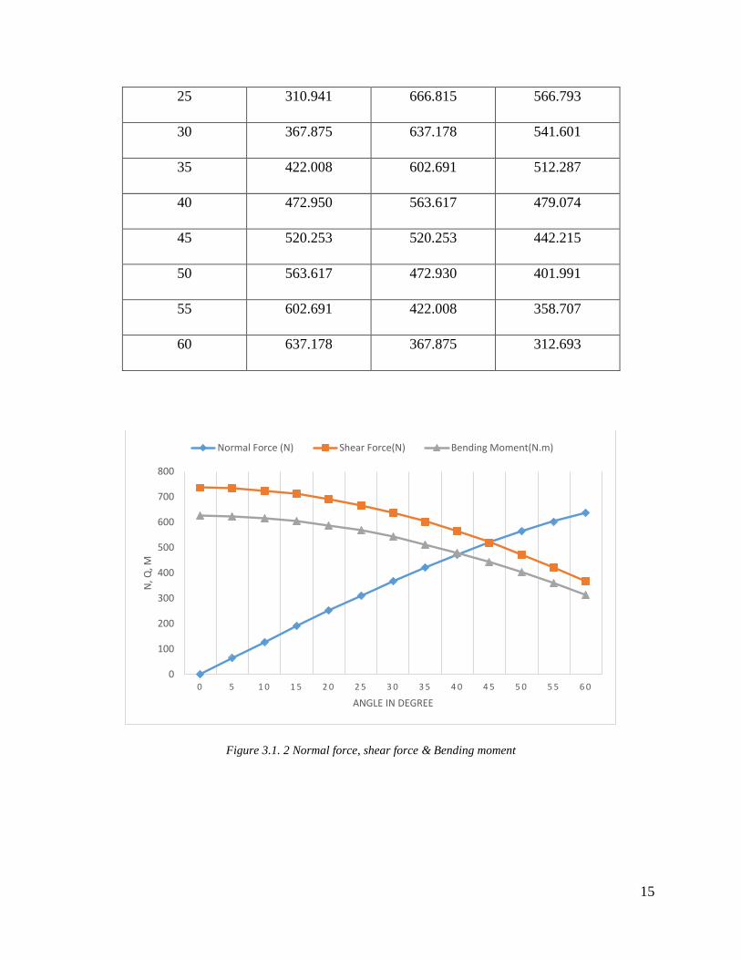
Figure 3.1. 2 Normal force, shear force & Bending moment .................................................. 15
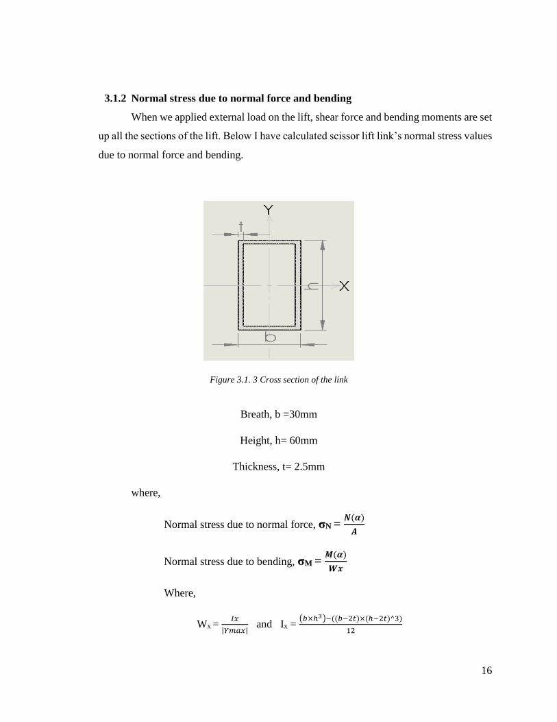
Figure 3.1. 3 Cross section of the link ..................................................................................... 16
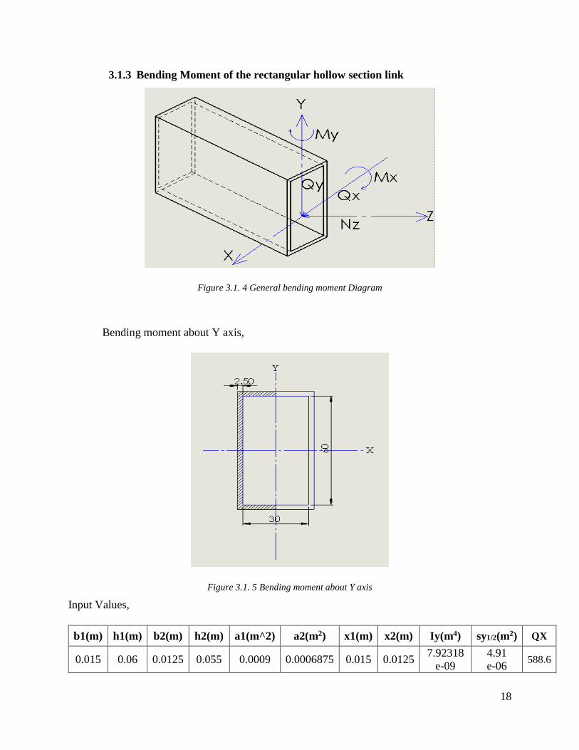
Figure 3.1. 4 General bending moment Diagram .................................................................... 18
Figure 3.1. 5 Bending moment about Y axis ........................................................................... 18
Figure 3.1. 6 Bending moment about X axis ........................................................................... 20
Figure 3.1. 7 stresses in bidirectional ....................................................................................... 22
Figure 3.1. 8 critical load ......................................................................................................... 25
Figure 3.1. 9 complex load acting section ............................................................................... 27
Figure 3.1. 10 stress elements .................................................................................................. 28
Figure 3.5. 1Bevel gear ............................................................................................................ 34
Figure 3.6. 1Ball bearing ......................................................................................................... 36
Figure 3.8. 1Ratchet ................................................................................................................. 38
Figure 3.8. 2 Pawl .................................................................................................................... 39
Figure 3.9. 1 Caster Wheel ...................................................................................................... 39
Figure 3.10. 1scissor lift at initial position .............................................................................. 40
Figure 3.10. 2 Scissor lift at final position ............................................................................... 40
Figure 3.10. 3 Mechanical drive setup in top plate bottom side .............................................. 41
xii
List of Tables
Table 3. 1 Scissor lift link position .......................................................................................... 12
Table 3.1. 1 Normal Force, Shear Force and Bending moment .............................................. 14
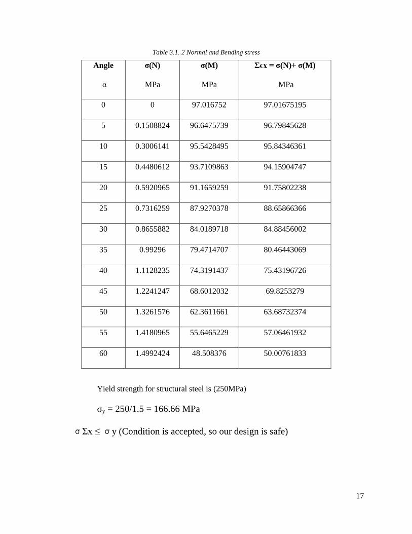
Table 3.1. 2 Normal and Bending stress .................................................................................. 17
Table 3.1. 3 Bending moment about Y axis ............................................................................. 19
Table 3.1. 4 Bending moment about X axis ............................................................................. 21
Table 3.1. 5 Bending about X & Y axis ................................................................................... 23
Table 3.3. 1 Platform calculations ........................................................................................... 31
Table 4. 1 Material Properties .................................................................................................. 46
Table 4. 2 Analysis Results ...................................................................................................... 60
Table 5. 1 Product cost............................................................................................................. 61
1
1. Introduction
Before the creation of weight lifting device like jack screw, pneumatic jack, hydraulic
jack, crane, etc., people lift the objects with the help of ropes and rollers. Due to the revolution and
development of science and technology, these days many upgraded technologies are used to lifting
stuffs.
Any machine part cannot be moved to a desired position with application of less amount
of external force. For placing a component in required location, the motion of component follows
commonly horizontal or vertical direction. Many machines such as aerial lift, boom lifts, scissor
lift, man lift, tele handler, towable lift are used to move machinery and manpower in different
directions based on the requirement. A scissor lift is a portable, easily extended and compressed,
safe operating machine used for transportation of medium sized components to its expected
position. A scissor lift is machine which moves in vertical direction using criss-cross 'X' pattern
scissor arms. The required elevation of the lift is achieved based on the number of criss-cross 'X'
pattern scissor arms attached. The scissor lift mechanism is based on linked arms in a criss-cross
'X' pattern which can be folded and extended in exact direction similar to a pantograph. Usually
upward motion is achieved by the application of pressure to the outside of the lowest set of
supports, elongating the crossing pattern, and propelling the work platform vertically upwards.
This project aims at making a scissor lift, that is easy to use/operate, elevated height limit,
cost effective and movable as well as reducing the maintenance cost. So that it’ll be used
conveniently used handily employed in day to day activities at home and may be used in garages,
hotels and many further applications. For these application in this project a scissor lift, which is
operated by a leadscrew mechanism, which is driven by the bevel gear is designed to lift material
and consumer to the desired height. Lift capability is up to 300 kilograms and it can be elevated
almost two-meter height that is suitable for the household application. The key inspiration of this
design of the lift is mechanical drive (leadscrew, bevel gear and Ratchet Pawl) that is fitted in
upper part of the lift.
1.1 Project Background
To pick and place stuffs, painting and to carrying light weight in a house or shop we are
usually necessary to use the ladder or elevator. Accordingly, a variety of scissor lifts have been
2
developed for lifting an object and consumer too. But for safety and cargo carrying purpose no one
prefer the ladder in a house, ladder is only used for terribly small functions. Due to this normally
individuals like the scissor lift rather than ladder for his or her safety and different functions.
Furthermore, scissor lifts which is usually accessible within the market are generally massive,
heavy, difficult to store, transport and expensive. In addition to the difficulties in repairing dispatch
and assembly process and maintenance process. Probably for in operation these elevator, less
physical effort is enough for the operator but user ought to be having knowledge and skills.
In light of such inherent disadvantages, commercial purpose user approaches
unremarkably equipped scissor lift, wherein such system is raised and lowered via pneumatic,
hydraulic or electrically-powered systems. However, because of the lift size, complex to operate,
purchasing and maintaining these lifts people not prepared to get this system for the household
application. So that during this project to avoiding these kind of difficulties and fulfil the
expectation of the individuals wants and desires, a scissor lift that is operated by mechanical drive
has been developed.
1.2 Project problem Statement
“Never attempt to solve all the matters at once- make them line up for one by one”.
According to the market basically today the lift machines provided victimization the hydraulic
system and alternative advanced system as a result of for obtaining the precise movement and
alternative functions. With the limitations encountered within the use of ropes, ladders, scaffold,
hydraulic and other advanced lifts in obtaining to elevated height like the quantity of load to be
carried, comfortable, time consumption, much etc. So what try to do this project proposal is an
inspiration of attempt to develop carry machines that not use the advanced systems however
mechanical drive scissors carry which can overcome the higher than declared limitations is
employed.
3
1.3 Scope of the study
The design of the scissor lift is to elevate up to a height of about three meter and carrying
capability of however 300 kilograms. For this requirements in this project I even ought to
calculation for the applicable dimensions of the mechanical parts of the lift, how to design the
scissor lift legs, upper plate, lower plate and the mechanical drive for the above same criteria and
ultimately we've design this system using SolidWorks 2014 package and analysis by using ANSYS
R14.5 package.
1.4 Project objective
Operational modelling according to different conditions of expectation.
Strength analysis of the structural elements consisting frame.
The device is limited to a mean load of 300 kilograms.
We should additionally concern alternative criteria. Such as
Expectation of selected materials
Transportation and
Safety related needs.
Targeted customers,
Household consumer
Warehouse consumer and
Utility and Painting contractor
1.5 Project importance
To design associate degree an analyze, a scissor lift is to carry the consumer along with
the belongings well and safely to a needed desired height. In this project, the mechanical drive
fixed in upper plate of the lift to use the consumer throughout its exportation, when consumer on
the upper plate of the lift. So that there's no have to be compelled to external help or help from a
second party as a result of the beginning of the planning. And the scissor lift should
be terribly easy, portable, strong, safety, very user friendly in handling method, environment
friendly and less maintenance cost.
4
2. Analysis of existing approaches
A scissor lift is a kind of platform that can normally just move vertically. The instrument
to accomplish this is the utilization of connected, collapsing underpins in a crosswise "X" design,
known as a pantograph (or scissor system) [1]. Scissor lifts are a specific kind of airborne lift,
intended to lift bigger loads and give more work space. Diesel or gas-fueled scissor lifts regularly
called harsh territory scissor lifts are better for open air use, yet can't be utilized inside. Scissor
lifts which is controlled by electric, pneumatic or mechanical drive, which settles on them a
superior decision for use in distribution centers or other indoor work. The most fundamental
thought while picking a scissor lift is weight carrying limit, the height we have to achieve, size and
price of the lift.
2.1 Medium duty scissor lifts available in market
SL.
No Name Description
Specifications
Platform
size
(length×
width)
mm
Lifting
height
mm
Lowered
height
mm
Net
Weight
Kg
Lifting
capacity
Kg
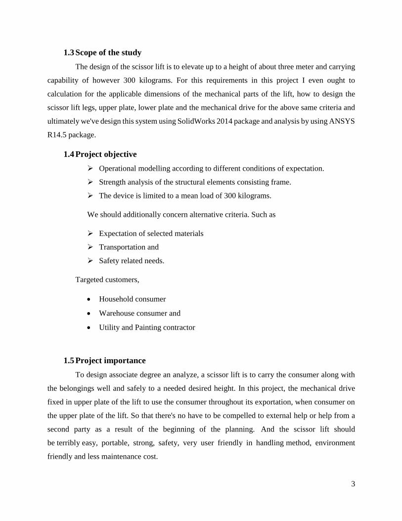
1
Manually operated lift [2]
This is
manually
operated
mobile
scissor lift,
which is
operated by
rotation of
handle
950×600 1100 450 85 250
5
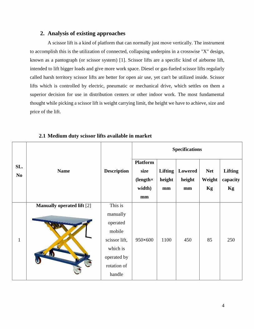
2
Air bag lift [2]
This lift
operated by
using
compressed
air to give
the linear
motion to the
system (Rise
and lower
operation)
1219×813 838.2 228.6 165 450
3
Hydraulic scissor lift [2]
This lift is
operated by
using
hydraulic
power. Lift
or lower the
operation by
simply
handy foot
pedal control
1010×520 1000 435 150 400
6
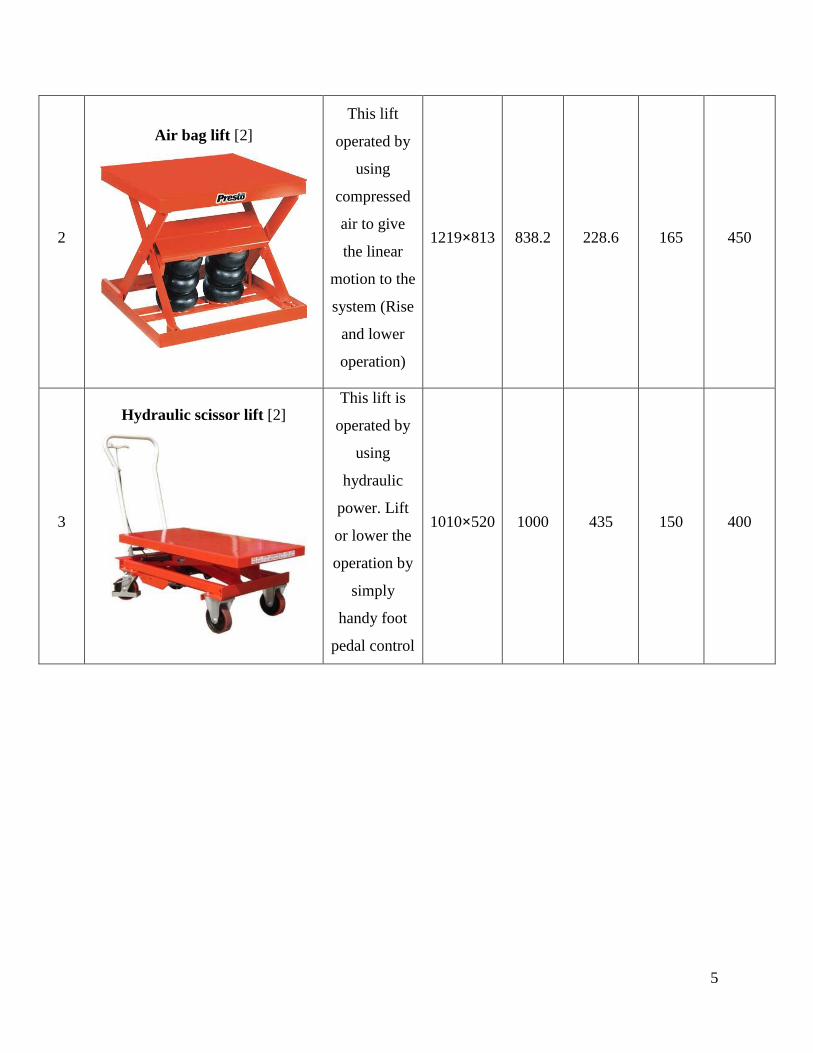
4
Double scissor lift [2]
Double
scissor lift
basically
operated by
hydraulic
power but it
has been
designed for
increasing
capable of
increasing
height limit.
1010×520 1500 450 180 500
On a comparative study of these various kinds of scissor lifts available in the market, we can
infer that
Incompact models, the highest height that they are able to lift is 1 meter.
More the height required, the more the weight of the lift becomes.
The price of the lifts increase as the capacity increases, which is more than affordable
(or) expensive for household purposes. On the other hand, they might be feasible for
commercial purposes.
7
2.2 Literature Review
Scissor lift design for use in the automotive industry [3]
Macaulay Oletu Stanley [3] discuss about what are lift available in the automotive
industry. Now recent years, numerous platforms or devices with various means that of application
have been made to be used within the automotive trade. He just said that how the automotive
industry has additionally expertise the flow of numerous lifting platform which is operated by
different power sources i.e. electrically operated lift, pneumatic operated lift and hydraulic
powered lift. Recent research additionally shows the use of restraint for raising or lowering load
(MichaelAdel, PE (2008): Scissors raise Deflection Understanding All these lifting devices have
contributed impressively to the automotive industries. This report presents a scissors mechanism
with a platform table that will be horizontal at each level. The proposed mechanism is a double
scissors for stability.
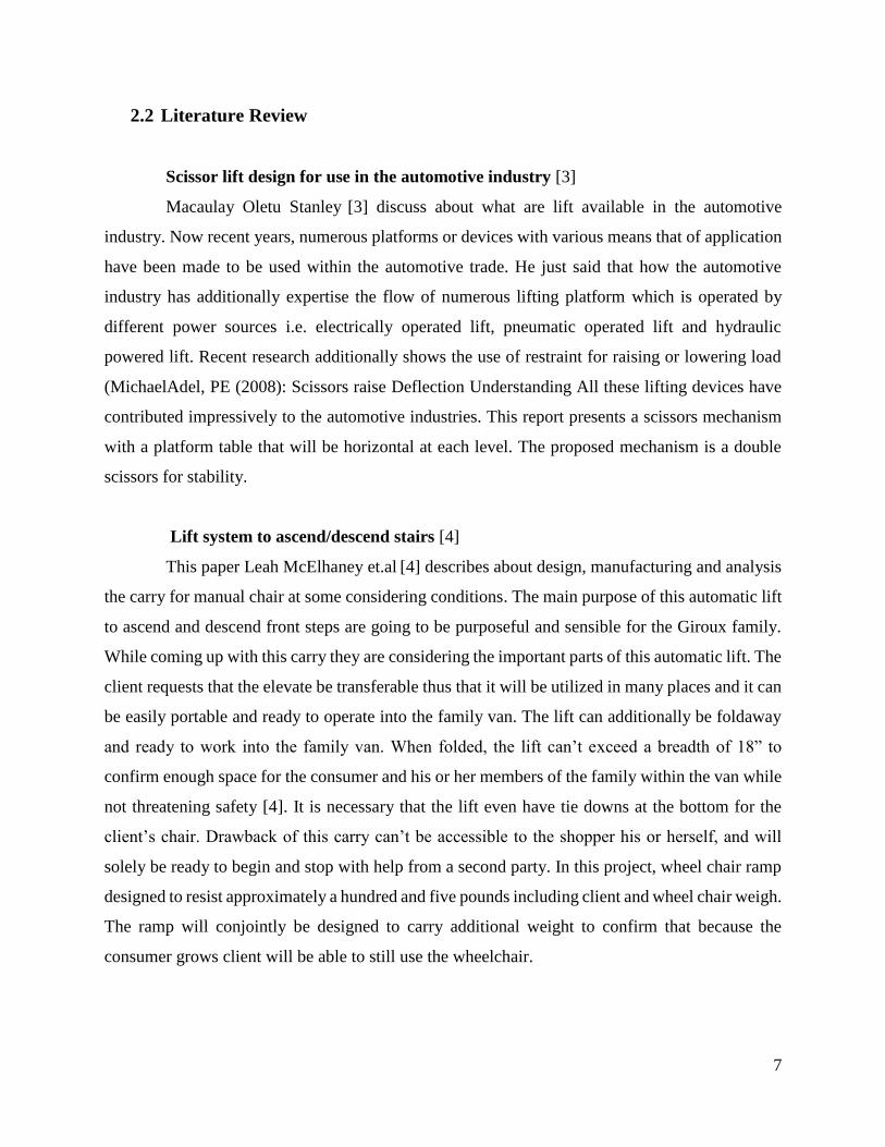
Lift system to ascend/descend stairs [4]
This paper Leah McElhaney et.al [4] describes about design, manufacturing and analysis
the carry for manual chair at some considering conditions. The main purpose of this automatic lift
to ascend and descend front steps are going to be purposeful and sensible for the Giroux family.
While coming up with this carry they are considering the important parts of this automatic lift. The
client requests that the elevate be transferable thus that it will be utilized in many places and it can
be easily portable and ready to operate into the family van. The lift can additionally be foldaway
and ready to work into the family van. When folded, the lift can’t exceed a breadth of 18” to
confirm enough space for the consumer and his or her members of the family within the van while
not threatening safety [4]. It is necessary that the lift even have tie downs at the bottom for the
client’s chair. Drawback of this carry can’t be accessible to the shopper his or herself, and will
solely be ready to begin and stop with help from a second party. In this project, wheel chair ramp
designed to resist approximately a hundred and five pounds including client and wheel chair weigh.
The ramp will conjointly be designed to carry additional weight to confirm that because the
consumer grows client will be able to still use the wheelchair.
8
Design, development and analysis of z-axis translation for an earth sensor test
facility [5]
Ghanashyam KG et.al [5] objective of the work is to design and auxiliary examination a
z-pivot interpretation for an earth finder check office within the Earth research center, Laboratory
for Electro-Optics System (LEOS), ISRO Bangalore. To develop a simple solution for the direction
hub interpretation, considering the physical and material restrictions in addition in light of the fact
that the administrator's safety and basic availability of the gadget. As of now there is an exist setup
of direction hub interpreters that has been implemented on a limited extent for an equipment
testing. This thesis the gadget established and exposes a comparatively new idea that's fitting
space, safety and easy-access requirements of the take a look at facility in the earth laboratory.
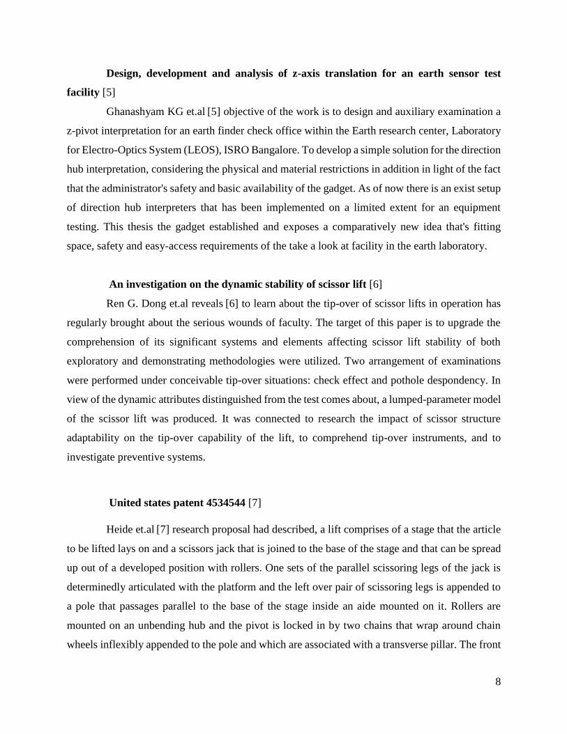
An investigation on the dynamic stability of scissor lift [6]
Ren G. Dong et.al reveals [6] to learn about the tip-over of scissor lifts in operation has
regularly brought about the serious wounds of faculty. The target of this paper is to upgrade the
comprehension of its significant systems and elements affecting scissor lift stability of both
exploratory and demonstrating methodologies were utilized. Two arrangement of examinations
were performed under conceivable tip-over situations: check effect and pothole despondency. In
view of the dynamic attributes distinguished from the test comes about, a lumped-parameter model
of the scissor lift was produced. It was connected to research the impact of scissor structure
adaptability on the tip-over capability of the lift, to comprehend tip-over instruments, and to
investigate preventive systems.
United states patent 4534544 [7]
Heide et.al [7] research proposal had described, a lift comprises of a stage that the article
to be lifted lays on and a scissors jack that is joined to the base of the stage and that can be spread
up out of a developed position with rollers. One sets of the parallel scissoring legs of the jack is
determinedly articulated with the platform and the left over pair of scissoring legs is appended to
a pole that passages parallel to the base of the stage inside an aide mounted on it. Rollers are
mounted on an unbending hub and the pivot is locked in by two chains that wrap around chain
wheels inflexibly appended to the pole and which are associated with a transverse pillar. The front
9
end of the transverse shaft is associated with a tensioning gadget that works parallel to the stage.
Two freely turning rollers are mounted on the hub on every side of the jack, every roller leans
against an assistant rail and mounted rail on each inside scissoring leg and the helper rails are
inside the jack. One end of every secondary rail is mounted on the pole and the helper rails and
guide rails are about half as long toward the free closures of the scissoring legs as the area of
scissoring leg that stretches out from the central to the free end of the scissoring parts.
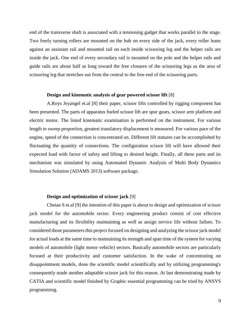
Design and kinematic analysis of gear powered scissor lift [8]
A.Roys Jeyangel et.al [8] their paper, scissor lifts controlled by rigging component has
been presented. The parts of apparatus fueled scissor lift are spur gears, scissor arm platform and
electric motor. The listed kinematic examination is performed on the instrument. For various
length to sweep proportion, greatest translatory displacement is measured. For various pace of the
engine, speed of the connection is concentrated on. Different lift statures can be accomplished by
fluctuating the quantity of connections. The configuration scissor lift will have allowed their
expected load with factor of safety and lifting to desired height. Finally, all these parts and its
mechanism was simulated by using Automated Dynamic Analysis of Multi Body Dynamics
Simulation Solution (ADAMS 2013) software package.
Design and optimization of scissor jack [9]
Chetan S et.al [9] the intention of this paper is about to design and optimization of scissor
jack model for the automobile sector. Every engineering product consist of cost effective
manufacturing and its flexibility maintaining as well as assign service life without failure. To
considered those parameters this project focused on designing and analyzing the scissor jack model
for actual loads at the same time to maintaining its strength and span time of the system for varying
models of automobile (light motor vehicle) sectors. Basically automobile sectors are particularly
focused at their productivity and customer satisfaction. In the wake of concentrating on
disappointment models, done the scientific model scientifically and by utilizing programming's
consequently made another adaptable scissor jack for this reason. At last demonstrating made by
CATIA and scientific model finished by Graphic essential programming can be tried by ANSYS
programming.
10
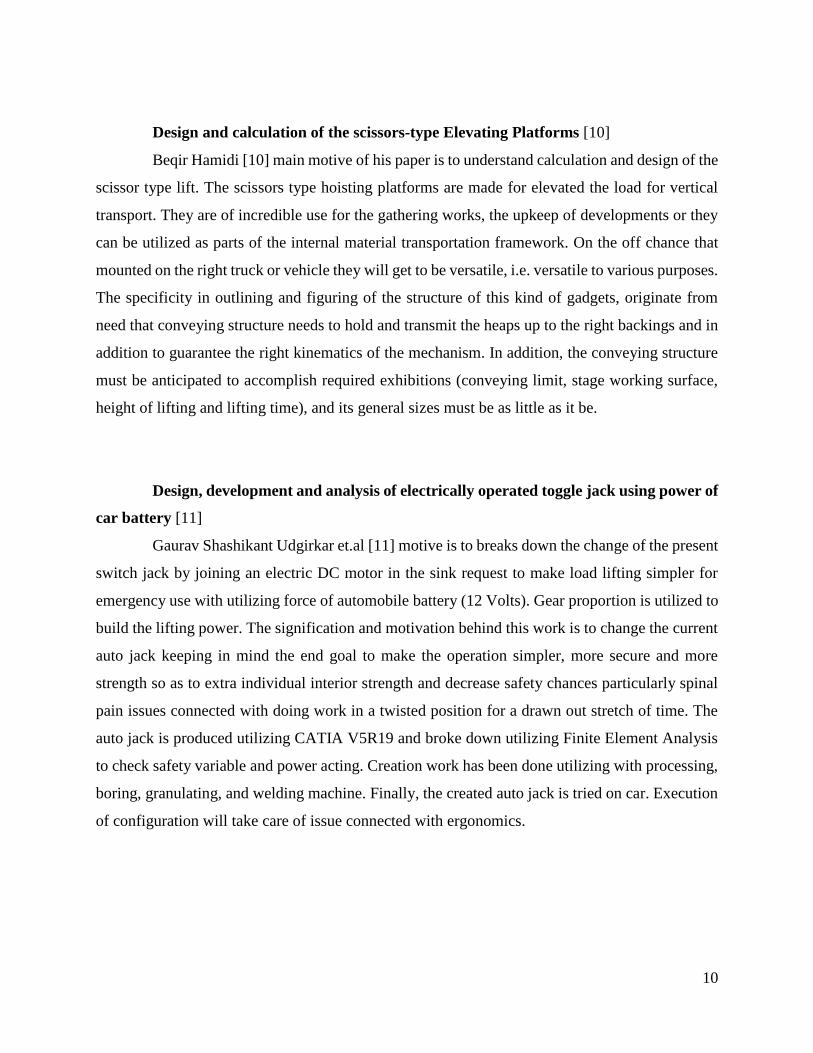
Design and calculation of the scissors-type Elevating Platforms [10]
Beqir Hamidi [10] main motive of his paper is to understand calculation and design of the
scissor type lift. The scissors type hoisting platforms are made for elevated the load for vertical
transport. They are of incredible use for the gathering works, the upkeep of developments or they
can be utilized as parts of the internal material transportation framework. On the off chance that
mounted on the right truck or vehicle they will get to be versatile, i.e. versatile to various purposes.
The specificity in outlining and figuring of the structure of this kind of gadgets, originate from
need that conveying structure needs to hold and transmit the heaps up to the right backings and in
addition to guarantee the right kinematics of the mechanism. In addition, the conveying structure
must be anticipated to accomplish required exhibitions (conveying limit, stage working surface,
height of lifting and lifting time), and its general sizes must be as little as it be.
Design, development and analysis of electrically operated toggle jack using power of
car battery [11]
Gaurav Shashikant Udgirkar et.al [11] motive is to breaks down the change of the present
switch jack by joining an electric DC motor in the sink request to make load lifting simpler for
emergency use with utilizing force of automobile battery (12 Volts). Gear proportion is utilized to
build the lifting power. The signification and motivation behind this work is to change the current
auto jack keeping in mind the end goal to make the operation simpler, more secure and more
strength so as to extra individual interior strength and decrease safety chances particularly spinal
pain issues connected with doing work in a twisted position for a drawn out stretch of time. The
auto jack is produced utilizing CATIA V5R19 and broke down utilizing Finite Element Analysis
to check safety variable and power acting. Creation work has been done utilizing with processing,
boring, granulating, and welding machine. Finally, the created auto jack is tried on car. Execution
of configuration will take care of issue connected with ergonomics.
11
Design and fabrication of a novel three-wheel robot with a SLE based lifting
mechanism and line tracking capability [12]
Shameek Ganguly et.al [12] manages the look and improvement of a standard three-wheel
robot able to do self-governing exploring an organized surroundings by recommends that of taking
after a sinusoidal line on the ground. Besides, it is outfitted with a deployable scissor lift with
partner complete effector plate accordingly giving application measured quality to the robot. The
primary application is imagined to work a programmed target-chasing vehicle in commercial
ventures like car and development wherever esteem adequacy is a vital measure for
computerization and quality might be an amazingly attractive usefulness. Mechanical design is
completed using stress examination with the help of the finite part programming system package
ANSYS and velocity reaction bends range unit created for the extremely non-linear movement of
the scissor lift. At last algorithm is created for fast line following abuse light-transmitting diode
and picture semiconductor device matches and comes about in terms of experimental data further
as simulated.
2.3 Conclusion
From the analyzed literatures we can see that the various kinds of scissor lifts are contrasted
from each other by the changes that are brought about in terms of their weights dimensions of the
links, and working area, material used in the links. Whereas, when it comes to the mechanism by
which the lifts are operated, most of them fall into the hydraulic system category which makes the
lifts heavy. On analyzing these models, we can clearly notice that there is not much emphasis
placed on the weight of the lifts, but there are only changes in layout of the hydraulic system which
makes one model different from the other.
12
3. Design calculations for scissor lift components
Scissor lift be made up of base platform, upper platform, lead screw, bevel gear, ratchet
& pawl, bolt, nut, links and pins. There is no outline strategy accessible for planning these parts.
On the basis of specific assumptions, the design for each of the components has been described as
follows.
In this section, execution of this outline taking into account the measurement different
numerical relations are produced. Here I have calculated normal force, shear force, bending
moment and buckling load for how scissor lift link responded for the applied load of 300kg. Then
for getting accurate result of strength and stability values (deformation and von-mises stress) by
utilizing Ansys software, which can helpful to understand whether our lift can carry required load
limit or not.
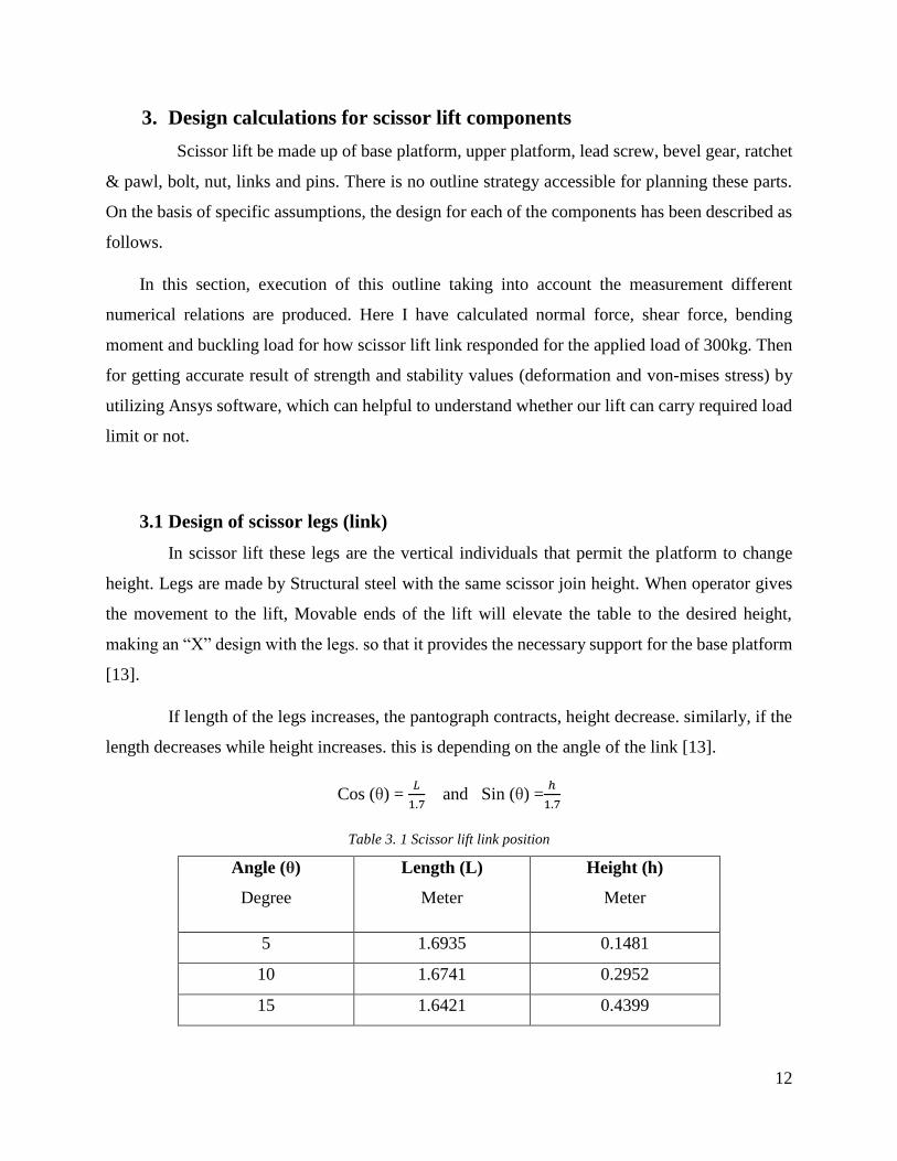
3.1 Design of scissor legs (link)
In scissor lift these legs are the vertical individuals that permit the platform to change
height. Legs are made by Structural steel with the same scissor join height. When operator gives
the movement to the lift, Movable ends of the lift will elevate the table to the desired height,
making an “X” design with the legs. so that it provides the necessary support for the base platform
[13].
If length of the legs increases, the pantograph contracts, height decrease. similarly, if the
length decreases while height increases. this is depending on the angle of the link [13].
Cos (θ) = 𝐿
1.7 and Sin (θ) =
ℎ
1.7
Table 3. 1 Scissor lift link position
Angle (θ)
Degree
Length (L)
Meter
Height (h)
Meter
5 1.6935 0.1481
10 1.6741 0.2952
15 1.6421 0.4399
13
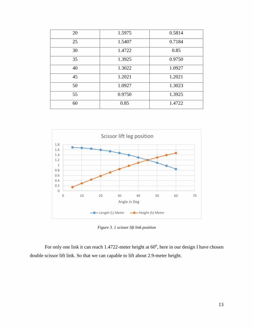
20 1.5975 0.5814
25 1.5407 0.7184
30 1.4722 0.85
35 1.3925 0.9750
40 1.3022 1.0927
45 1.2021 1.2021
50 1.0927 1.3023
55 0.9750 1.3925
60 0.85 1.4722
Figure 3. 1 scissor lift link position
For only one link it can reach 1.4722-meter height at 600, here in our design I have chosen
double scissor lift link. So that we can capable to lift about 2.9-meter height.
0
0.2
0.4
0.6
0.8
1
1.2
1.4
1.6
1.8
0 10 20 30 40 50 60 70
Angle in Deg
Scissor lift leg position
Length (L) Meter Height (h) Meter
14
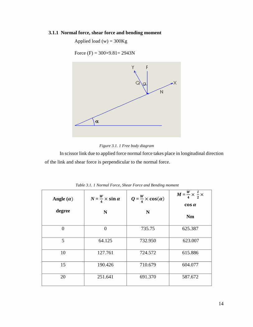
3.1.1 Normal force, shear force and bending moment
Applied load (w) = 300Kg
Force (F) = 300×9.81= 2943N
Figure 3.1. 1 Free body diagram
In scissor link due to applied force normal force takes place in longitudinal direction
of the link and shear force is perpendicular to the normal force.
Table 3.1. 1 Normal Force, Shear Force and Bending moment
Angle (𝜶)
degree
N = 𝑾
𝟒× 𝐬𝐢𝐧 𝜶
N
Q = 𝑾
𝟒× 𝐜𝐨𝐬(𝜶)
N
M = 𝑾
𝟒×
𝒍
𝟐×
𝐜𝐨𝐬 𝜶
Nm
0 0 735.75 625.387
5 64.125 732.950 623.007
10 127.761 724.572 615.886
15 190.426 710.679 604.077
20 251.641 691.370 587.672
15
25 310.941 666.815 566.793
30 367.875 637.178 541.601
35 422.008 602.691 512.287
40 472.950 563.617 479.074
45 520.253 520.253 442.215
50 563.617 472.930 401.991
55 602.691 422.008 358.707
60 637.178 367.875 312.693
Figure 3.1. 2 Normal force, shear force & Bending moment
0
100
200
300
400
500
600
700
800
0 5 1 0 1 5 2 0 2 5 3 0 3 5 4 0 4 5 5 0 5 5 6 0
N, Q
, M
ANGLE IN DEGREE
Normal Force (N) Shear Force(N) Bending Moment(N.m)
16
3.1.2 Normal stress due to normal force and bending
When we applied external load on the lift, shear force and bending moments are set
up all the sections of the lift. Below I have calculated scissor lift link’s normal stress values
due to normal force and bending.
Figure 3.1. 3 Cross section of the link
Breath, b =30mm
Height, h= 60mm
Thickness, t= 2.5mm
where,
Normal stress due to normal force, σN = 𝑵(𝜶)
𝑨
Normal stress due to bending, σM = 𝑴(𝜶)
𝑾𝒙
Where,
Wx = 𝐼𝑥
|𝑌𝑚𝑎𝑥| and Ix =
(𝑏×ℎ3)−((𝑏−2𝑡)×(ℎ−2𝑡)^3)
12
17
Table 3.1. 2 Normal and Bending stress
Angle
α
σ(N)
MPa
σ(M)
MPa
Σϵx = σ(N)+ σ(M)
MPa
0 0 97.016752 97.01675195
5 0.1508824 96.6475739 96.79845628
10 0.3006141 95.5428495 95.84346361
15 0.4480612 93.7109863 94.15904747
20 0.5920965 91.1659259 91.75802238
25 0.7316259 87.9270378 88.65866366
30 0.8655882 84.0189718 84.88456002
35 0.99296 79.4714707 80.46443069
40 1.1128235 74.3191437 75.43196726
45 1.2241247 68.6012032 69.8253279
50 1.3261576 62.3611661 63.68732374
55 1.4180965 55.6465229 57.06461932
60 1.4992424 48.508376 50.00761833
Yield strength for structural steel is (250MPa)
σy = 250/1.5 = 166.66 MPa
σΣx ≤ σy (Condition is accepted, so our design is safe)
18
3.1.3 Bending Moment of the rectangular hollow section link
Figure 3.1. 4 General bending moment Diagram
Bending moment about Y axis,
Figure 3.1. 5 Bending moment about Y axis
Input Values,
b1(m) h1(m) b2(m) h2(m) a1(m^2) a2(m2) x1(m) x2(m) Iy(m4) sy1/2(m2) QX
0.015 0.06 0.0125 0.055 0.0009 0.0006875 0.015 0.0125 7.92318
e-09
4.91
e-06 588.6
19
Where,
b1, h1, a1, x1- values for outer rectangular
b2, h2, a2, x2- values for outer rectangular
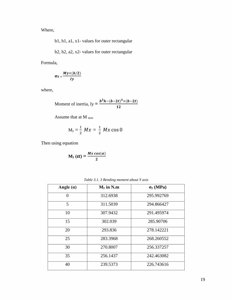
Formula,
σY = 𝑴𝒚×(𝒃/𝟐)
𝑰𝒚
where,
Moment of inertia, Iy = 𝒃𝟑𝒉−(𝒃−𝟐𝒕)𝟑×(𝒉−𝟐𝒕)
𝟏𝟐
Assume that at M max
My = 1
2 𝑀𝑥 =
1
2 𝑀𝑥 cos 0
Then using equation
My (𝜶) = 𝑴𝒙 𝒄𝒐𝒔(𝜶)
𝟐
Table 3.1. 3 Bending moment about Y axis
Angle (α) My in N.m σy (MPa)
0 312.6938 295.992769
5 311.5039 294.866427
10 307.9432 291.495974
15 302.039 285.90706
20 293.836 278.142221
25 283.3968 268.260552
30 270.8007 256.337257
35 256.1437 242.463082
40 239.5373 226.743616
20
45 221.1079 209.298494
50 200.9957 190.260485
55 179.3538 169.774478
60 156.3469 147.996385
τzx = 𝑸𝒙×𝑺𝒚𝟏/𝟐
𝑰𝒚×𝒉
where,
𝑺𝒚𝟏/𝟐 = (a1×x1) – (a2×x2)
Therefore,
τzx = 6.07462284 MPa
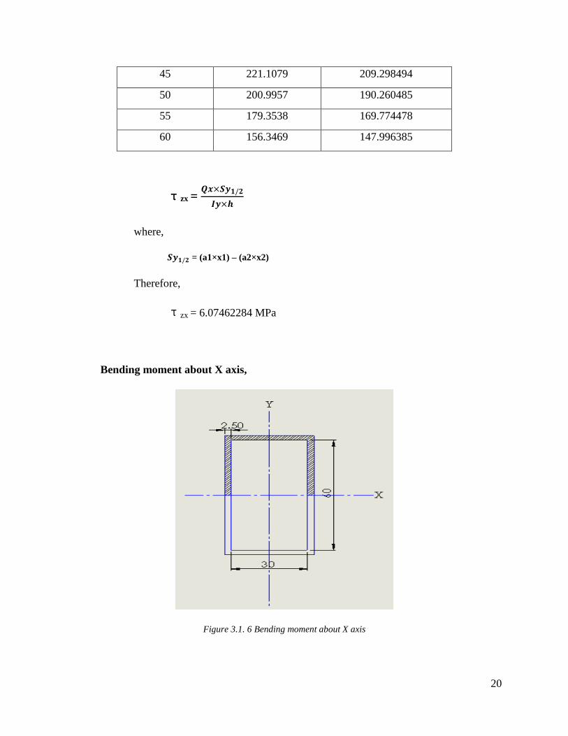
Bending moment about X axis,
Figure 3.1. 6 Bending moment about X axis
21
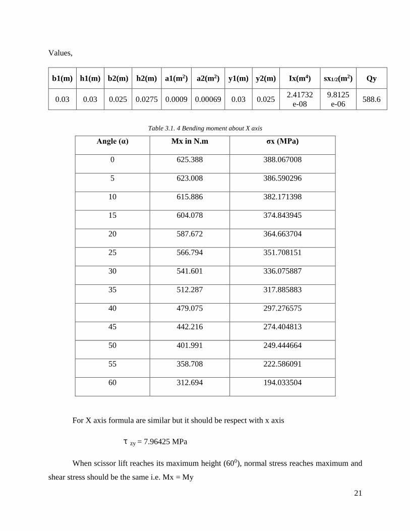
Values,
b1(m) h1(m) b2(m) h2(m) a1(m2) a2(m2) y1(m) y2(m) Ix(m4) sx1/2(m2) Qy
0.03 0.03 0.025 0.0275 0.0009 0.00069 0.03 0.025 2.41732
e-08
9.8125
e-06 588.6
Table 3.1. 4 Bending moment about X axis
Angle (α) Mx in N.m σx (MPa)
0 625.388 388.067008
5 623.008 386.590296
10 615.886 382.171398
15 604.078 374.843945
20 587.672 364.663704
25 566.794 351.708151
30 541.601 336.075887
35 512.287 317.885883
40 479.075 297.276575
45 442.216 274.404813
50 401.991 249.444664
55 358.708 222.586091
60 312.694 194.033504
For X axis formula are similar but it should be respect with x axis
τzy = 7.96425 MPa
When scissor lift reaches its maximum height (600), normal stress reaches maximum and
shear stress should be the same i.e. Mx = My
22
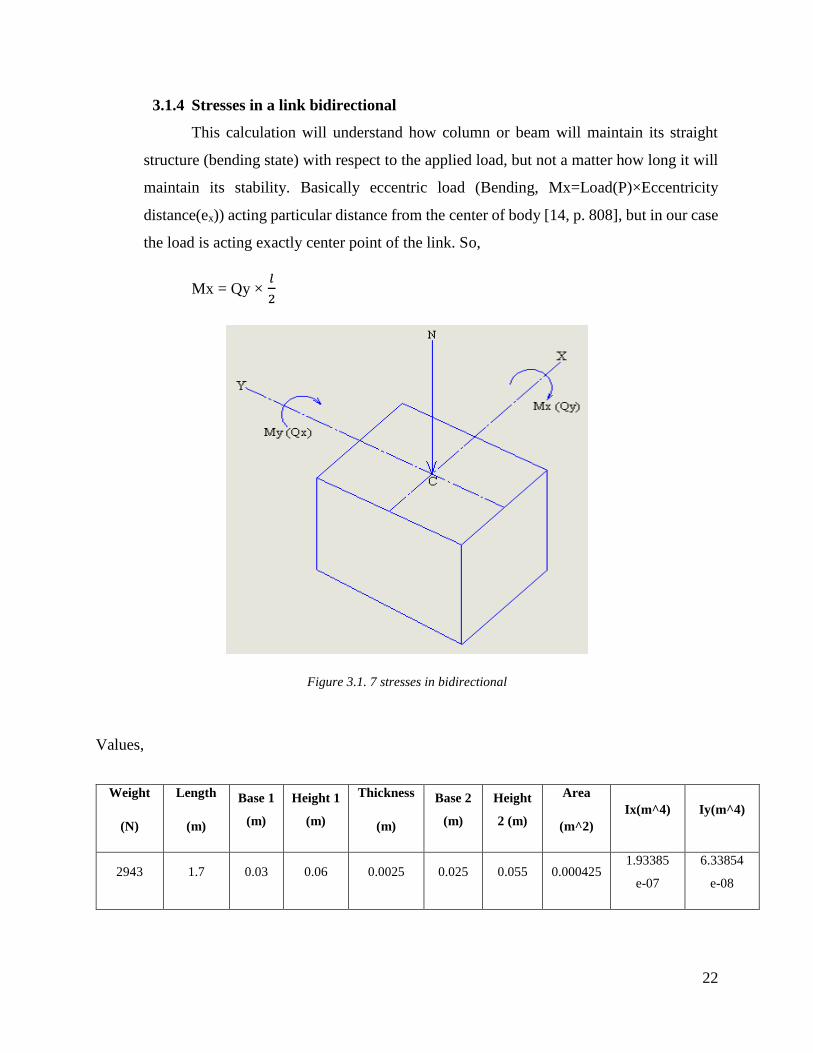
3.1.4 Stresses in a link bidirectional
This calculation will understand how column or beam will maintain its straight
structure (bending state) with respect to the applied load, but not a matter how long it will
maintain its stability. Basically eccentric load (Bending, Mx=Load(P)×Eccentricity
distance(ex)) acting particular distance from the center of body [14, p. 808], but in our case
the load is acting exactly center point of the link. So,
Mx = Qy × 𝑙
2
Figure 3.1. 7 stresses in bidirectional
Values,
Weight
(N)
Length
(m)
Base 1
(m)
Height 1
(m)
Thickness
(m)
Base 2
(m)
Height
2 (m)
Area
(m^2)
Ix(m^4) Iy(m^4)
2943 1.7 0.03 0.06 0.0025 0.025 0.055 0.000425 1.93385
e-07
6.33854
e-08
23
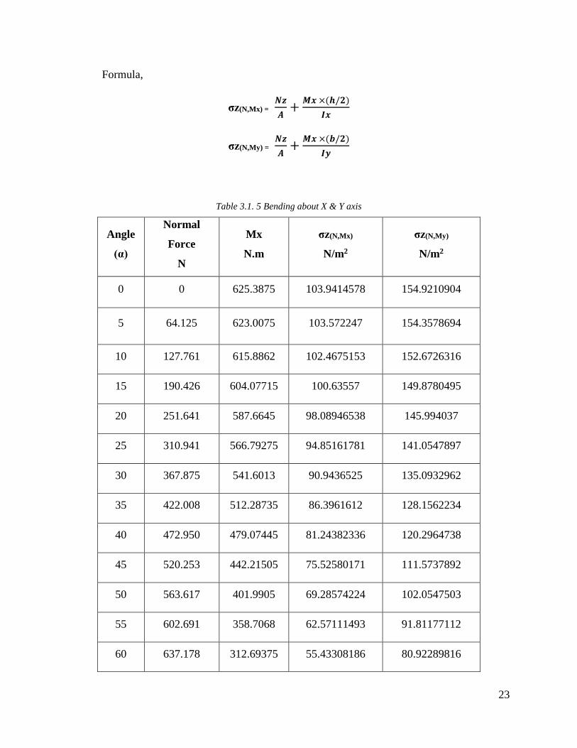
Formula,
σz(N,Mx) = 𝑵𝒛
𝑨+
𝑴𝒙 ×(𝒉/𝟐)
𝑰𝒙
σz(N,My) = 𝑵𝒛
𝑨+
𝑴𝒙 ×(𝒃/𝟐)
𝑰𝒚
Table 3.1. 5 Bending about X & Y axis
Angle
(α)
Normal
Force
N
Mx
N.m
σz(N,Mx)
N/m2
σz(N,My)
N/m2
0 0 625.3875 103.9414578 154.9210904
5 64.125 623.0075 103.572247 154.3578694
10 127.761 615.8862 102.4675153 152.6726316
15 190.426 604.07715 100.63557 149.8780495
20 251.641 587.6645 98.08946538 145.994037
25 310.941 566.79275 94.85161781 141.0547897
30 367.875 541.6013 90.9436525 135.0932962
35 422.008 512.28735 86.3961612 128.1562234
40 472.950 479.07445 81.24382336 120.2964738
45 520.253 442.21505 75.52580171 111.5737892
50 563.617 401.9905 69.28574224 102.0547503
55 602.691 358.7068 62.57111493 91.81177112
60 637.178 312.69375 55.43308186 80.92289816
24
Interaction Method,
For X axis
𝐅
𝐀+
𝐌𝐱 ×(𝐡/𝟐)
𝐈𝐱
𝛔𝐚𝐥𝐥 ≤ 𝟏
Where,
σall = σy/ FOS [Structural steel Yield strength value]
Therefore 0.623649 ≤ 1
Similarly,
For Y axis
𝐅
𝐀+
𝐌𝐲 ×(𝐛/𝟐)
𝐈𝐲
𝛔𝐚𝐥𝐥 ≤ 𝟏
Therefore 0.9252 ≤ 1
The above condition is satisfied for our dimension of the link, so design will be safe.
3.1.5 Euler Equation
This equation is used to find out Euler’s critical load i.e. longitudinal compression
load on the scissor lift link. Therefore, we can understand the lift link will remain maintain their
state straight or bending for the applied load on the link. Suppose if the link will starts deflect
which cause the link to bend and broke by buckling load. So that load should lower than the critical
load for avoiding unstable equilibrium.
25
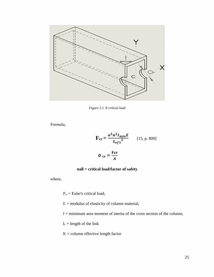
Figure 3.1. 8 critical load
Formula,
Fcr = 𝒏𝟐𝝅𝟐𝑰𝒎𝒊𝒏𝑬
𝑳𝒆𝒇𝟏𝟐 [15, p. 808]
σcr = 𝐅𝐜𝐫
𝑨
σall = critical load/factor of safety
where,
Pcr = Euler's critical load,
E = modulus of elasticity of column material,
I = minimum area moment of inertia of the cross section of the column,
L = length of the link
K = column effective length factor
26
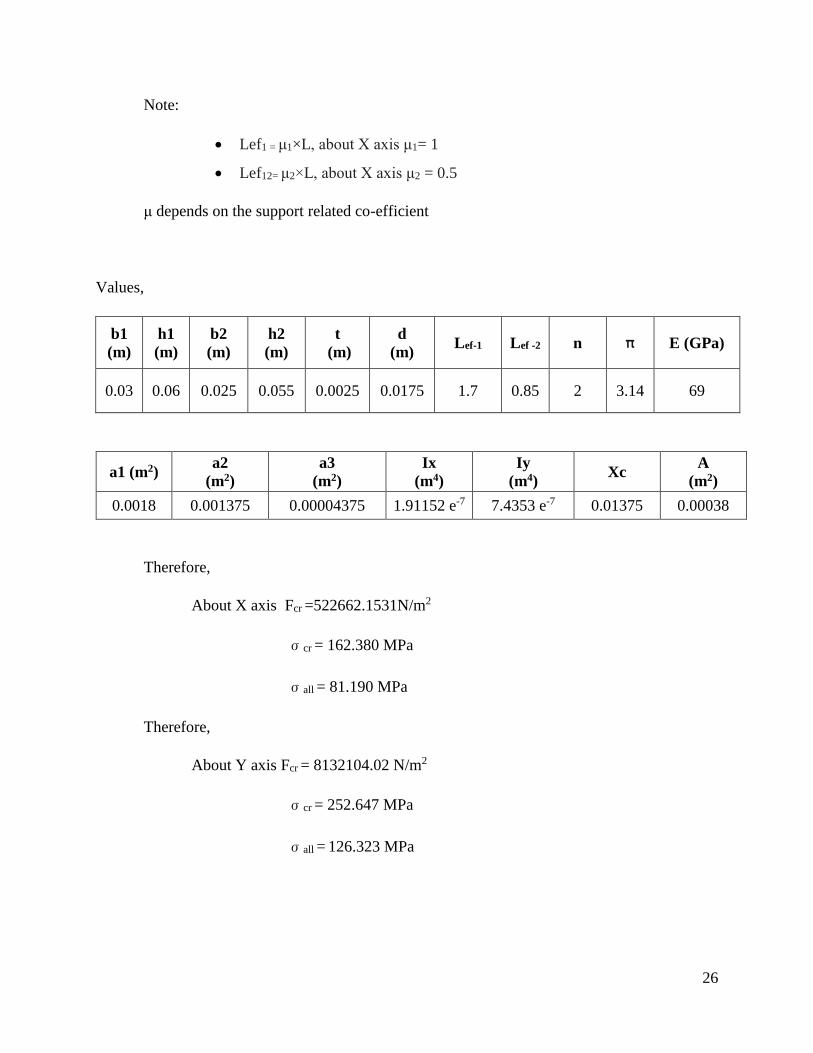
Note:
Lef1 = μ1×L, about X axis μ1= 1
Lef12= μ2×L, about X axis μ2 = 0.5
μ depends on the support related co-efficient
Values,
b1
(m)
h1
(m)
b2
(m)
h2
(m)
t
(m)
d
(m) Lef-1 Lef -2 n π E (GPa)
0.03 0.06 0.025 0.055 0.0025 0.0175 1.7 0.85 2 3.14 69
a1 (m2) a2
(m2)
a3
(m2)
Ix
(m4)
Iy
(m4) Xc
A
(m2)
0.0018 0.001375 0.00004375 1.91152 e-7 7.4353 e-7 0.01375 0.00038
Therefore,
About X axis Fcr =522662.1531N/m2
σcr = 162.380 MPa
σall = 81.190 MPa
Therefore,
About Y axis Fcr = 8132104.02 N/m2
σcr = 252.647 MPa
σall = 126.323 MPa
27
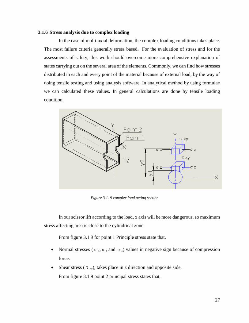
3.1.6 Stress analysis due to complex loading
In the case of multi-axial deformation, the complex loading conditions takes place.
The most failure criteria generally stress based. For the evaluation of stress and for the
assessments of safety, this work should overcome more comprehensive explanation of
states carrying out on the several area of the elements. Commonly, we can find how stresses
distributed in each and every point of the material because of external load, by the way of
doing tensile testing and using analysis software. In analytical method by using formulae
we can calculated these values. In general calculations are done by tensile loading
condition.
Figure 3.1. 9 complex load acting section
In our scissor lift according to the load, x axis will be more dangerous. so maximum
stress affecting area is close to the cylindrical zone.
From figure 3.1.9 for point 1 Principle stress state that,
Normal stresses (σx,σy and σz) values in negative sign because of compression
force.
Shear stress (τzy), takes place in z direction and opposite side.
From figure 3.1.9 point 2 principal stress states that,
28
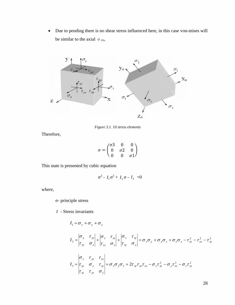
Due to pending there is no shear stress influenced here, in this case von-mises will
be similar to the axial σzx,
Figure 3.1. 10 stress elements
Therefore,
𝜎 = (𝜎3 0 00 𝜎2 00 0 𝜎1
)
This state is presented by cubic equation
σ3 - 1I σ2 +
2I σ - 3I =0
where,
σ- principle stress
I - Stress invariants
zyxI 1
222
2 xyzxyzxzzyyx
yxy
xyx
xzx
zxz
zyz
yzyI
222
3 2 xyzzxyyzxzxyzxyzyx
zyzxz
zyyxy
zxyxx
I
29
Principal stresses,
;cos3
11 c
I ;
3
2cos
3
12
c
I ,
3
2cos
3
13
c
I
Where,
;3
2
2
1 II
a ;33
2 321
3
1 IIII
b
;
32
ac .
3arccos
3
1
ac
b
By using this above formula, we can find the principle stress and shear stress values
for any point of the material.
Von- mises stress,
Due to the complex loading acting on the material, at particular time it tends to start yielding.
So that von mises used to determine yielding of the material. This maximum stress value can
be calculated from the Cauchy stress tensor. In generally von-mises stress equation is
𝜎𝑣 = √1
2⌈(𝜎𝑥 − 𝜎𝑦)2 + (𝜎𝑦 − 𝜎𝑧)2 + (𝜎𝑧 − 𝜎𝑥)2 + 6(𝜏2𝑥𝑦 + 𝜏2𝑦𝑧 + 𝜏2𝑧𝑥)⌉ [16]
For 2 dimensional stress state, 𝜎𝑧 = 0.
Principal stress,
𝜎𝑣 = √1
2⌈(𝜎1 − 𝜎2)2 + (𝜎2 − 𝜎3)2 + (𝜎3 − 𝜎1)2⌉ [17]
So by using stress tensor and von mises equations for the complex loading conditions, we
can predict the values of maximum stress acting on the section.
I have find this von-mises stress values by the help of ansys package. It will give very accurate
values of von mises stress and we can clearly understand where it will occur minimum and
maximum in the element.
30
3.2 Design of base plate
Usually, in scissor lift the base plate is mounted to the floor. it is constructed using
structural steel. It gives the proper balance to the structure additionally it should be rigidly
supported from underneath to support the point loading created by the two scissor leg roller and
the two scissor leg hinges. The base plate has attached by four wheel.
Length (l) = 1800 mm
Breadth (b) = 900 mm
Thickness (t) = 6 mm
3.3 Design of upper plate
The upper plate in a scissor lift is utilized to put the load and exchange it to the lift legs.
The outlining of the upper plate is attempted comparative as the base plate. It is likewise comprised
of structural steel material. Additional setup of this upper plate gives operator comfortable and
security.
Length (l) = 1800 mm
Breadth (b) = 900 mm
Thickness (t) = 6 mm
It is required to design a platform which should serve under heavy load application and
withstand high stresses. Structural steel has high compressive and tensile strength, good stability
and reliability. Furthermore, it is widely used in industries for manufacturing structural shape steel
members, such as c- beam, I- beam, hollow structural section (Rectangular, square and pipe). So
that the above mentioned and many other purpose this material should be suitable for our scissor
lift [18].
31
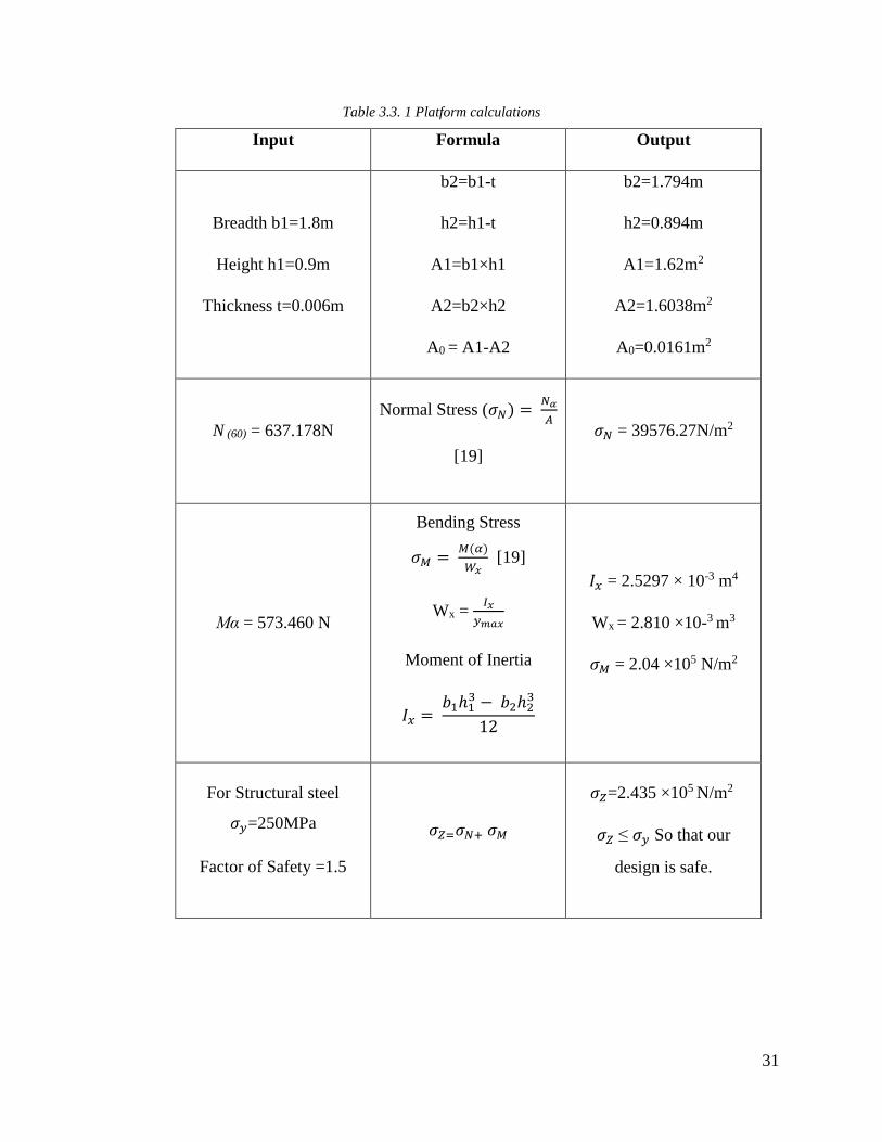
Table 3.3. 1 Platform calculations
Input Formula Output
Breadth b1=1.8m
Height h1=0.9m
Thickness t=0.006m
b2=b1-t
h2=h1-t
A1=b1×h1
A2=b2×h2
A0 = A1-A2
b2=1.794m
h2=0.894m
A1=1.62m2
A2=1.6038m2
A0=0.0161m2
N (60) = 637.178N
Normal Stress (𝜎𝑁) = 𝑁𝛼
𝐴
[19]
𝜎𝑁 = 39576.27N/m2
Mα = 573.460 N
Bending Stress
𝜎𝑀 = 𝑀(𝛼)
𝑊𝑥 [19]
Wx = 𝐼𝑥
𝑦𝑚𝑎𝑥
Moment of Inertia
𝐼𝑥 = 𝑏1ℎ1
3 − 𝑏2ℎ23
12
𝐼𝑥 = 2.5297 × 10⁻³ m4
Wx = 2.810 ×10⁻³ m3
𝜎𝑀 = 2.04 ×10⁵ N/m2
For Structural steel
𝜎𝑦=250MPa
Factor of Safety =1.5
𝜎𝑍=𝜎𝑁+ 𝜎𝑀
𝜎𝑍=2.435 ×10⁵ N/m2
𝜎𝑍 ≤ 𝜎𝑦 So that our
design is safe.
32
3.4 Design of leadscrew
Lead screw is an important part in a scissor lift, that takes up the operator or considerable
load to be lifted or brought down by lift. A lead screw is a component that converts rotational
movement to straight(linear) movement [20]. The most widely recognized frame comprises of a
cylindrical shaped shaft with helical grooves or edges called threads around the outside. The fasten
goes through a gap another object or medium, with threads within the gap that mesh with the
screw's threads. At the point. When the shaft of the screw is turned with respect to the stationary
threads, the screw moves along its pivot in respect to the medium encompassing it.
Lead screw can enhance constrain; a little rotational compel (torque) on the [14]pole can
apply a substantial hub drive on a heap. The littler the pitch, the separation between the screws'
strings, the more noteworthy the mechanical preferred standpoint, the proportion of yield to info
constrain.
There is a large contact range among male and female threads in lead screws and this
outcomes vast frictional loss amid the operation. Because of these frictional misfortunes, lead
screws are not exceptionally proficient but generally self-locking. In self-locking lead screws, the
load can't bring down itself without an outside exertion. Because of this feature it is generally used
to hold loads. so that in our scissor lift subsequent to lifting required stature assume in the event
that we discharge the hand from handle our framework effectively won't permit to move
downwards.
Outer diameter of screw rod, d0 = 60mm
Root diameter of screw rod, d1 = 50 mm
Length between supports, L = 2000 mm
Lead or pitch of screw rod, p = 10 mm
Mean diameter (d) = d0 - 𝑝
2 = 55mm
Coefficient of friction (μ) = tan ϕ = 0.15
tan α = 𝑝
𝜋𝑑
=0.05787
33
Frictional force
F = µ x P
= 0.15 x 2943
F = 1611.24 N
Force required to rising the load P = W× tan (α + ϕ) = w[tan∝+ 𝑡𝑎𝑛 𝜙)
1−𝑡𝑎𝑛𝛼 𝑡𝑎𝑛𝜙] [20, p. 634]
= 617.12N
Force required to lower the load P = W× tan (α - ϕ) = w[tan∝− 𝑡𝑎𝑛 𝜙)
1+𝑡𝑎𝑛𝛼 𝑡𝑎𝑛𝜙] [20, p. 634]
= 268.80N
3.5 Design of Bevel gear
Gears are rotating machine part having cut teeth or pinion, which meshed with another
toothed part to transmit the power. Gears can change the speed and torque through their gear ratio
furthermore it is used to change the direction of input power source. Gears are classified according
to the orientation of axis such as Parallel axis (Spur Gear, Helical Gear, Gear Rack and Internal
Gear), Intersecting axis (Miter Gear, Straight Bevel Gear, Spiral Bevel Gear) and Non-Intersecting
axis (Screw Gear, Worm, Worm Gear).
Bevel gears are gears, axes of the two shafts intersect and the tooth-bearing faces of the gears
themselves are conically shaped. bevel gears are frequently mounted on shafts that are 90 degrees
apart, however can be intended to work at different angles too. The pitch surface of the bevel gear
is a cone [20, p. 1080]. In this project I have selected straight bevel gear for giving rotational
motion to the lead screw. Here in this design we used two bevel gear, one is attached in handle and
another one is attached in leadscrew. Both are having same number of teeth.
34
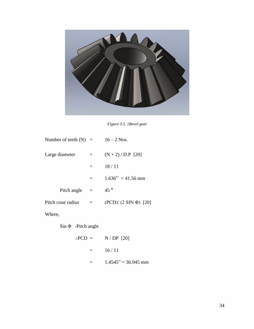
Figure 3.5. 1Bevel gear
Number of teeth (N) = 16 – 2 Nos.
Large diameter = (N + 2) / D.P [20]
= 18 / 11
= 1.636” = 41.56 mm
Pitch angle = 45 ⁰
Pitch cone radius = (PCD)/ (2 SIN Φ) [20]
Where,
Sin Φ -Pitch angle
∴PCD = N / DP [20]
= 16 / 11
= 1.4545” = 36.945 mm
35
Therefore,
Pitch cone radius = 36.945 / 2 Sin45
= 26.124mm
Dedendum Angle = Tan⁻¹ {(Dedendum / Pitch cone Radius)} [20]
Where,
Dedendum = 1.157 / DP
= 1.157 / 11
= 2.672 mm
∴Dedendum Angle = Tan⁻¹ {2.672 / 26.124) [20]
= 5⁰ 50”
Cutting Angle = Pitch angle – Dedendum angle
= 45⁰ - 5⁰50” = 39⁰ 30”
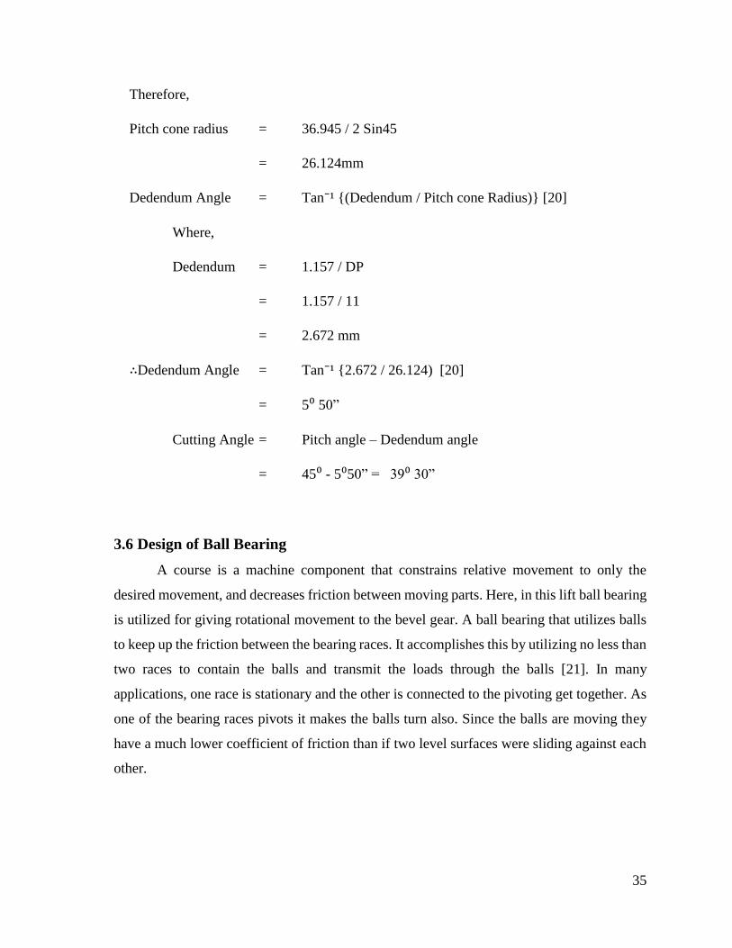
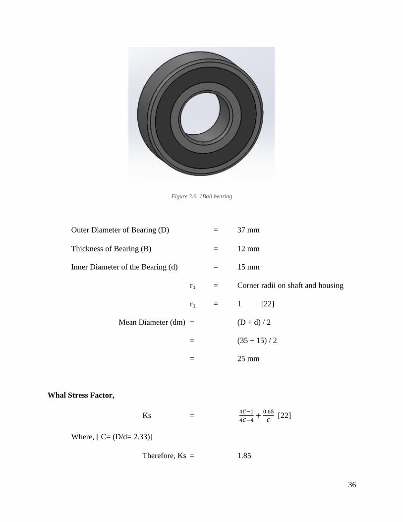
3.6 Design of Ball Bearing
A course is a machine component that constrains relative movement to only the
desired movement, and decreases friction between moving parts. Here, in this lift ball bearing
is utilized for giving rotational movement to the bevel gear. A ball bearing that utilizes balls
to keep up the friction between the bearing races. It accomplishes this by utilizing no less than
two races to contain the balls and transmit the loads through the balls [21]. In many
applications, one race is stationary and the other is connected to the pivoting get together. As
one of the bearing races pivots it makes the balls turn also. Since the balls are moving they
have a much lower coefficient of friction than if two level surfaces were sliding against each
other.
36
Figure 3.6. 1Ball bearing
Outer Diameter of Bearing (D) = 37 mm
Thickness of Bearing (B) = 12 mm
Inner Diameter of the Bearing (d) = 15 mm
r₁ = Corner radii on shaft and housing
r₁ = 1 [22]
Mean Diameter (dm) = (D + d) / 2
= (35 + 15) / 2
= 25 mm
Whal Stress Factor,
Ks = 4𝐶−1
4𝐶−4+
0.65
𝐶 [22]
Where, [ C= (D/d= 2.33)]
Therefore, Ks = 1.85
37
3.7 Bolt & Nut calculation
Bolt and Nuts are used to connect one end of the link to another end of the scissor lift
link.
Basic diameter, D = 40 mm
Screw thread pitch, p = 6 mm
Length of thread engagement, l = 60 mm
Pitch circle diameter, dp = (D - 0.64952. p) [22]
= 36 mm
Stress area formula:
Tensile stress area of the (male) screw
At = 𝜋
4(𝐷 − 0.938194. 𝑝)2 [23]
= 1197.77 mm2
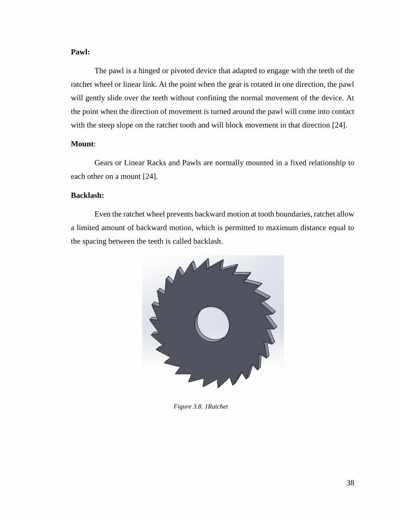
3.8 Ratchet and Pawl
Ratchet is a mechanical device that permits consistent straight or turning movement in just
a single direction. A ratchet is made out of three primary parts: round gear, pawl and a base or
mount [24].
Ratchet:
Ratchets created from gears are regularly round and are made out of uniform but
asymmetric teeth intended to confine movement to a single direction. The edges on one
side of the gear's teeth have moderate or gradual slope (frequently almost perpendicular to
the tangent of the gear's circumference) while alternate edges of the gear's teeth have a
much steeper slope [24].
38
Pawl:
The pawl is a hinged or pivoted device that adapted to engage with the teeth of the
ratchet wheel or linear link. At the point when the gear is rotated in one direction, the pawl
will gently slide over the teeth without confining the normal movement of the device. At
the point when the direction of movement is turned around the pawl will come into contact
with the steep slope on the ratchet tooth and will block movement in that direction [24].
Mount:
Gears or Linear Racks and Pawls are normally mounted in a fixed relationship to
each other on a mount [24].
Backlash:
Even the ratchet wheel prevents backward motion at tooth boundaries, ratchet allow
a limited amount of backward motion, which is permitted to maximum distance equal to
the spacing between the teeth is called backlash.
Figure 3.8. 1Ratchet
39
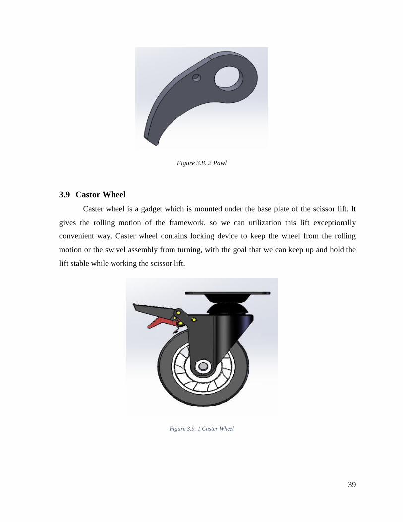
Figure 3.8. 2 Pawl
3.9 Castor Wheel
Caster wheel is a gadget which is mounted under the base plate of the scissor lift. It
gives the rolling motion of the framework, so we can utilization this lift exceptionally
convenient way. Caster wheel contains locking device to keep the wheel from the rolling
motion or the swivel assembly from turning, with the goal that we can keep up and hold the
lift stable while working the scissor lift.
Figure 3.9. 1 Caster Wheel
40
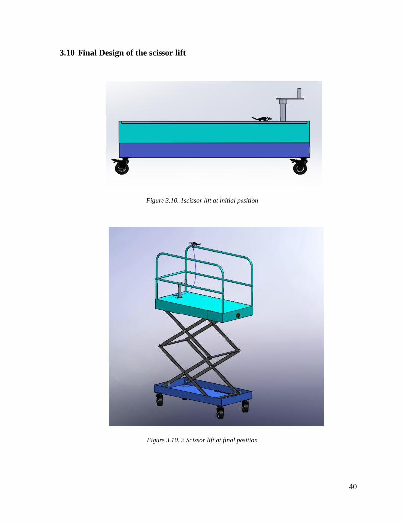
3.10 Final Design of the scissor lift
Figure 3.10. 1scissor lift at initial position
Figure 3.10. 2 Scissor lift at final position
41
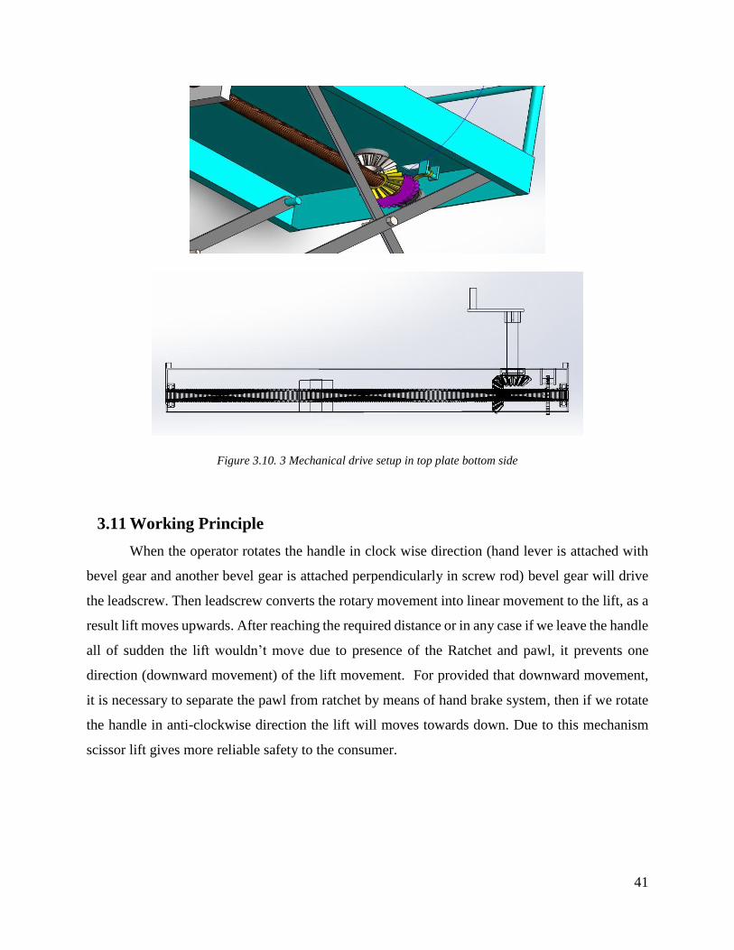
Figure 3.10. 3 Mechanical drive setup in top plate bottom side
3.11 Working Principle
When the operator rotates the handle in clock wise direction (hand lever is attached with
bevel gear and another bevel gear is attached perpendicularly in screw rod) bevel gear will drive
the leadscrew. Then leadscrew converts the rotary movement into linear movement to the lift, as a
result lift moves upwards. After reaching the required distance or in any case if we leave the handle
all of sudden the lift wouldn’t move due to presence of the Ratchet and pawl, it prevents one
direction (downward movement) of the lift movement. For provided that downward movement,
it is necessary to separate the pawl from ratchet by means of hand brake system, then if we rotate
the handle in anti-clockwise direction the lift will moves towards down. Due to this mechanism
scissor lift gives more reliable safety to the consumer.
42
4. Simulation Procedure
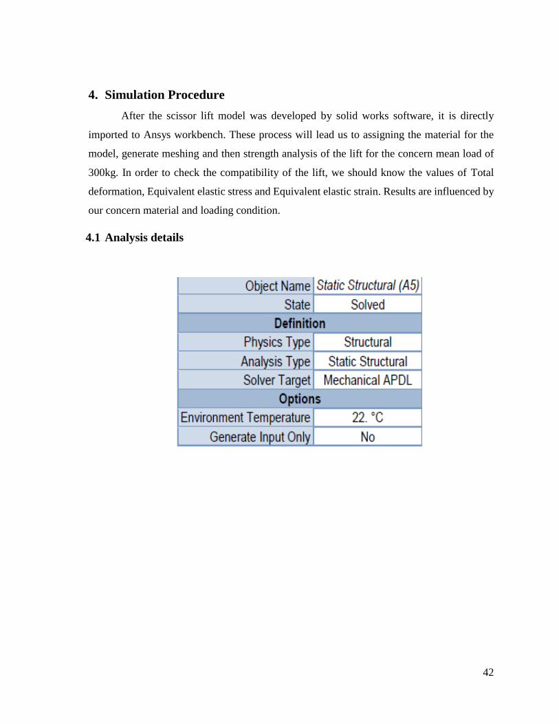
After the scissor lift model was developed by solid works software, it is directly
imported to Ansys workbench. These process will lead us to assigning the material for the
model, generate meshing and then strength analysis of the lift for the concern mean load of
300kg. In order to check the compatibility of the lift, we should know the values of Total
deformation, Equivalent elastic stress and Equivalent elastic strain. Results are influenced by
our concern material and loading condition.
4.1 Analysis details
43
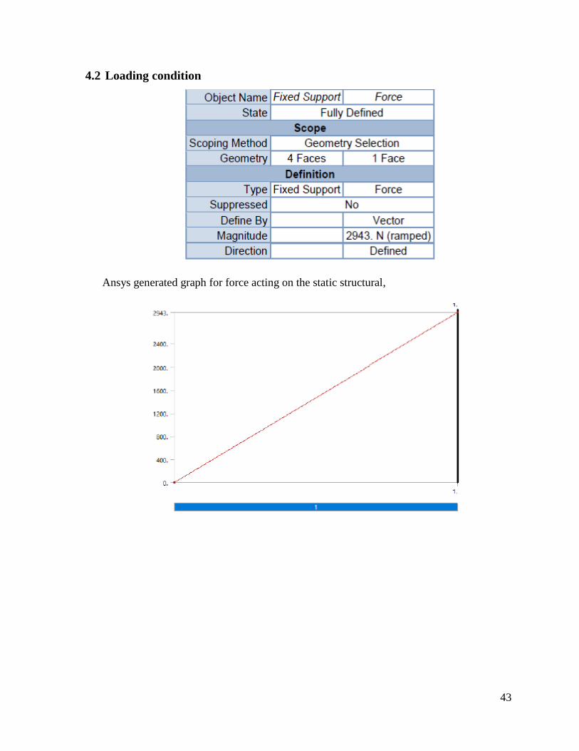
4.2 Loading condition
Ansys generated graph for force acting on the static structural,
44
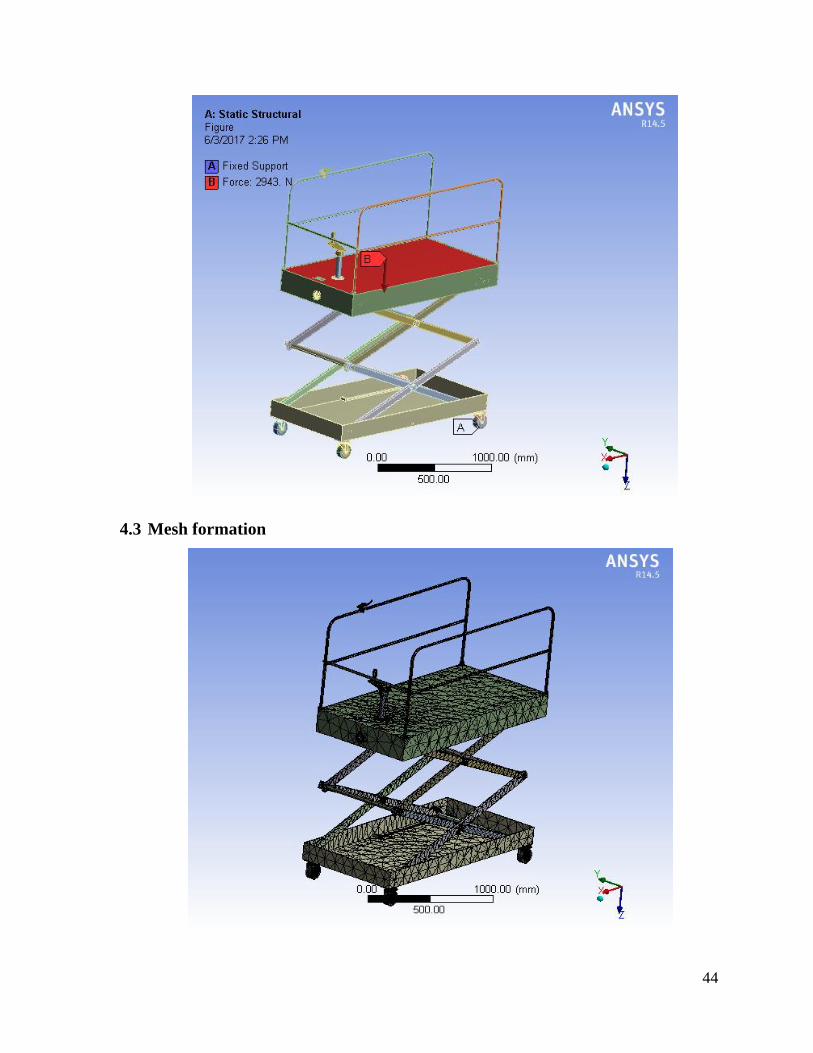
4.3 Mesh formation
45
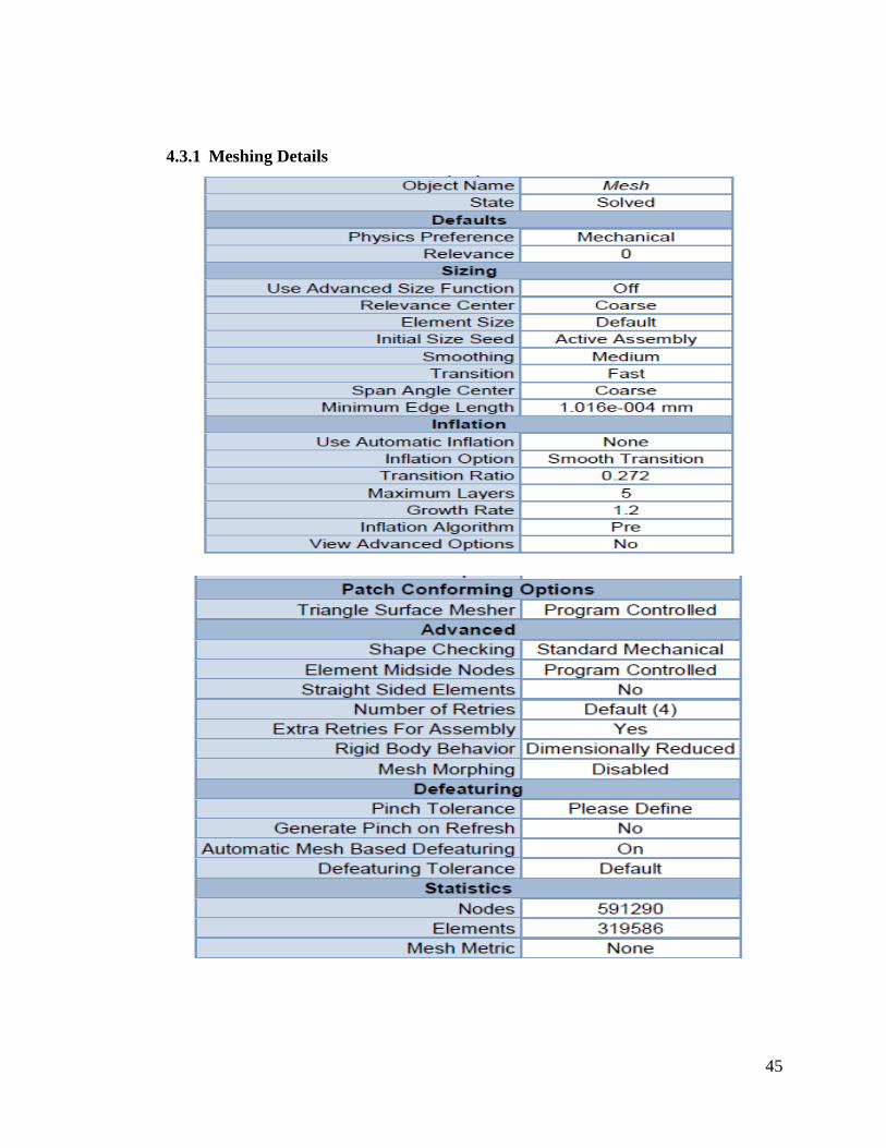
4.3.1 Meshing Details
46
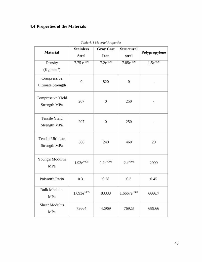
4.4 Properties of the Materials
Table 4. 1 Material Properties
Material Stainless
Steel
Gray Cast
Iron
Structural
steel Polypropylene
Density
(Kg.mm-3)
7.75 e-006
7.2e-006
7.85e-006
1.5e-006
Compressive
Ultimate Strength 0 820 0 -
Compressive Yield
Strength MPa 207 0 250 -
Tensile Yield
Strength MPa 207 0 250 -
Tensile Ultimate
Strength MPa 586 240 460 20
Young's Modulus
MPa 1.93e+005 1.1e+005 2.e+006 2000
Poisson's Ratio 0.31 0.28 0.3 0.45
Bulk Modulus
MPa 1.693e+005 83333 1.6667e+005 6666.7
Shear Modulus
MPa 73664 42969 76923 689.66
47
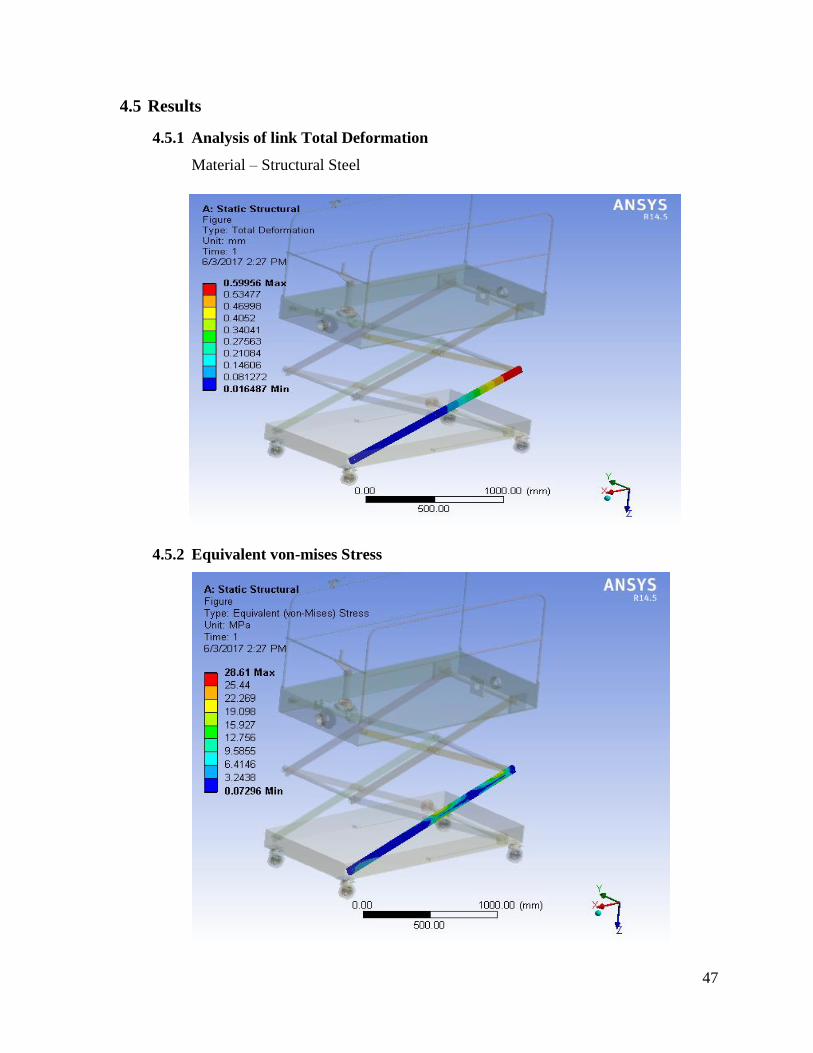
4.5 Results
4.5.1 Analysis of link Total Deformation
Material – Structural Steel
4.5.2 Equivalent von-mises Stress
48
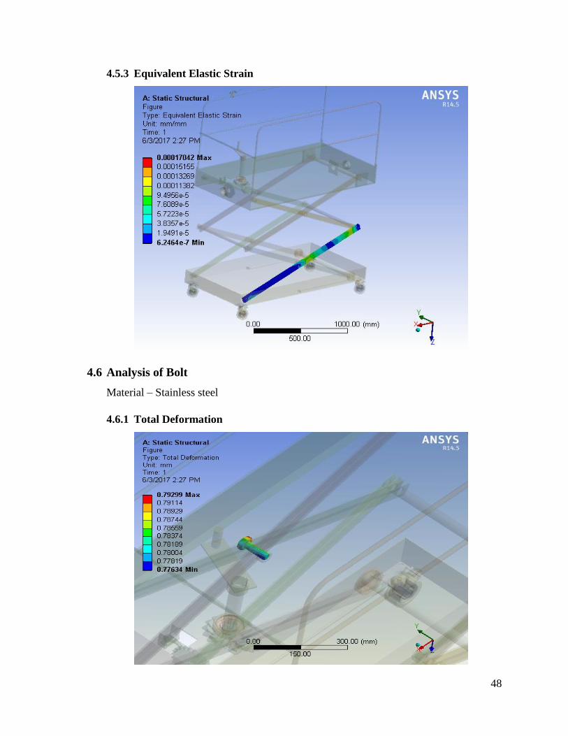
4.5.3 Equivalent Elastic Strain
4.6 Analysis of Bolt
Material – Stainless steel
4.6.1 Total Deformation
49
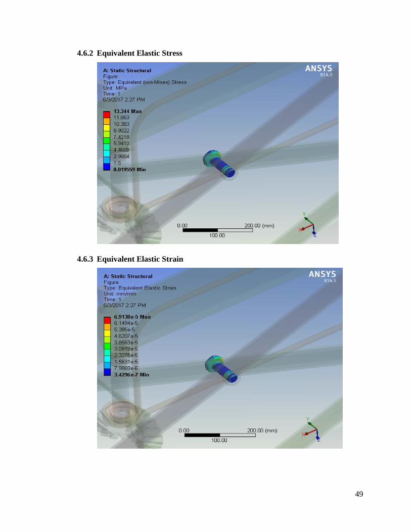
4.6.2 Equivalent Elastic Stress
4.6.3 Equivalent Elastic Strain
50
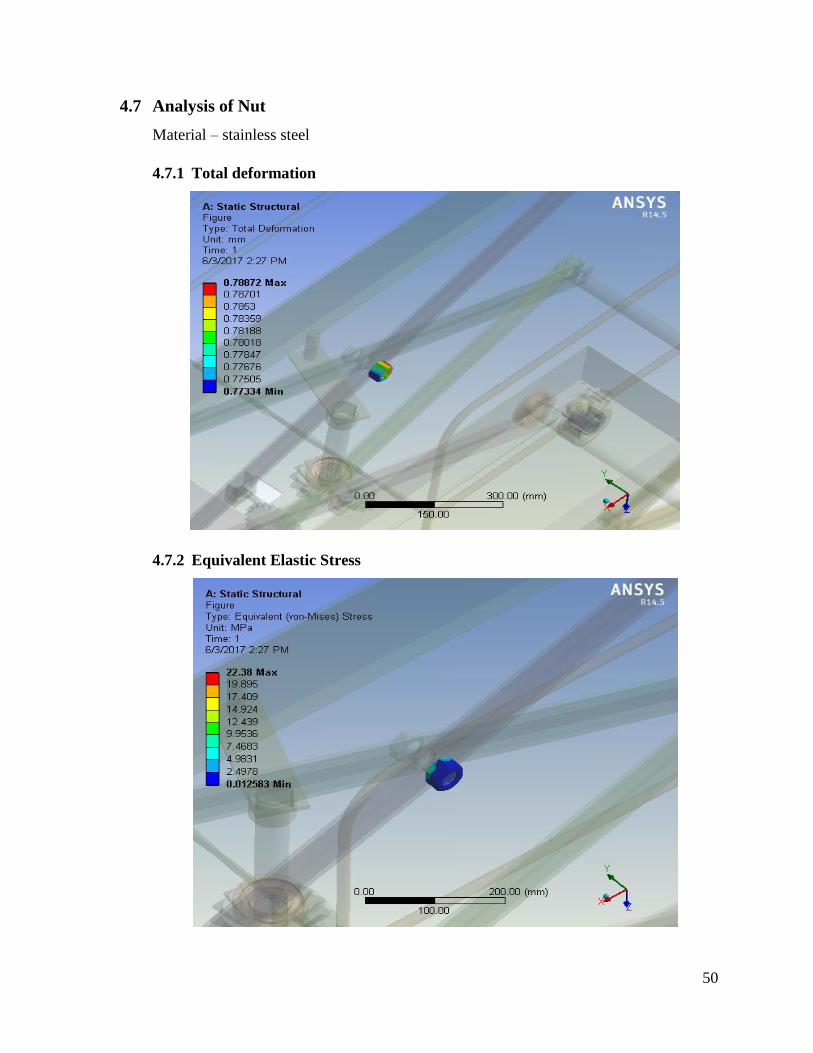
4.7 Analysis of Nut
Material – stainless steel
4.7.1 Total deformation
4.7.2 Equivalent Elastic Stress
51
4.7.3 Equivalent Elastic Strain
4.8 Analysis of Bearing
Material - stainless steel
4.8.1 Total Deformation
52
4.8.2 Equivalent Elastic Stress
4.8.3 Equivalent Elastic Strain
53
4.9 Bevel Gear
Material – Gray Cast Iron
4.9.1 Total Deformation
4.9.2 Equivalent Elastic Stress
54
4.9.3 Equivalent Elastic Strain
4.10 Analysis of Connecting Link
Material – Stainless steel
4.10.1 Total Deformation
55
4.10.2 Equivalent Elastic Stress
4.10.3 Equivalent Elastic Strain
56
4.11 Analysis of Caster Wheel
Material – Poly Propylene
4.11.1 Total Deformation
4.11.2 Equivalent Elastic Stress
57
4.11.3 Equivalent Elastic Strain
4.12 Analysis the structure of scissor lift model
Here we can see how the forces acting on the scissor lift and how it executes under the
mean load 300Kg.
4.12.1 Total Deformation
58
4.12.2 Equivalent Elastic Stress
4.12.3 Equivalent Elastic Strain
59
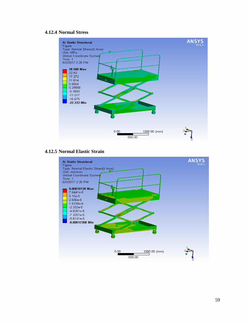
4.12.4 Normal Stress
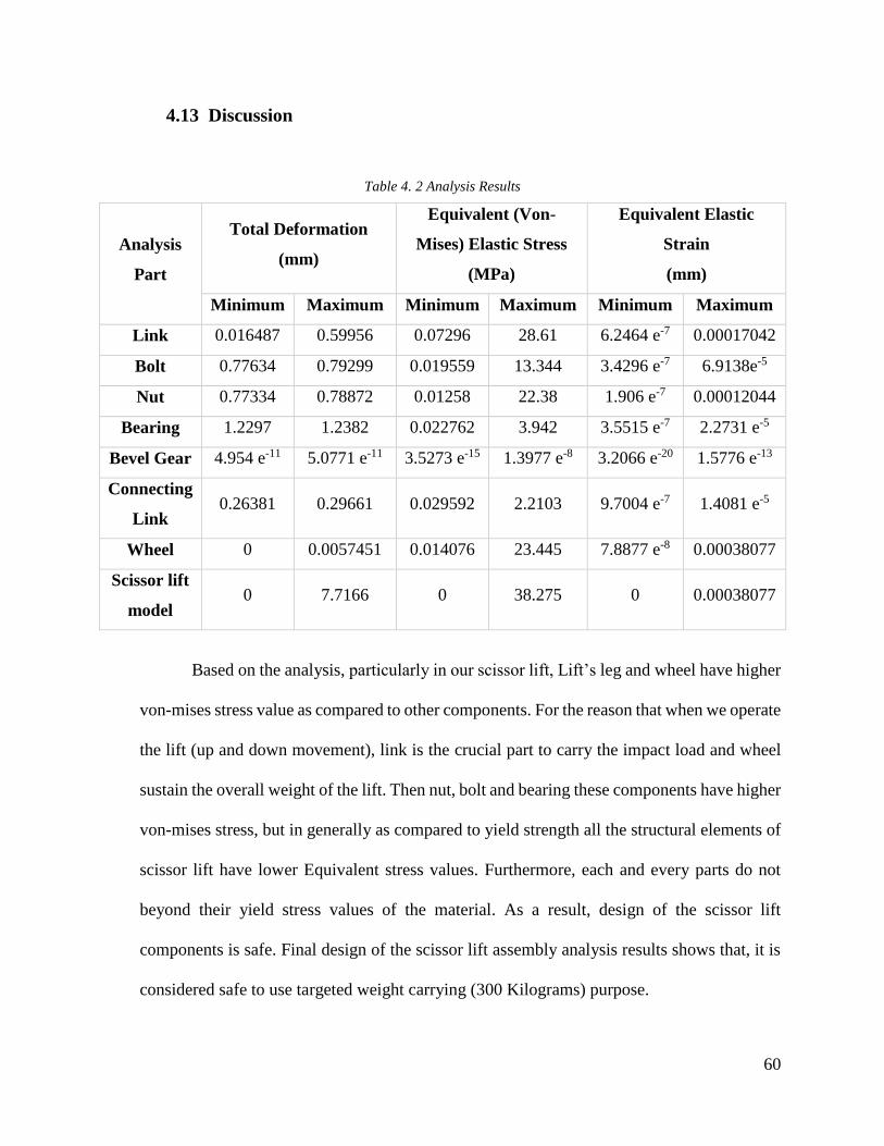
4.12.5 Normal Elastic Strain
60
4.13 Discussion
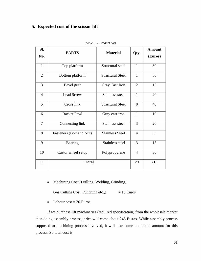
Table 4. 2 Analysis Results
Analysis
Part
Total Deformation
(mm)
Equivalent (Von-
Mises) Elastic Stress
(MPa)
Equivalent Elastic
Strain
(mm)
Minimum Maximum Minimum Maximum Minimum Maximum
Link 0.016487 0.59956 0.07296 28.61 6.2464 e-7 0.00017042
Bolt 0.77634 0.79299 0.019559 13.344 3.4296 e-7 6.9138e-5
Nut 0.77334 0.78872 0.01258 22.38 1.906 e-7 0.00012044
Bearing 1.2297 1.2382 0.022762 3.942 3.5515 e-7 2.2731 e-5
Bevel Gear 4.954 e-11 5.0771 e-11 3.5273 e-15 1.3977 e-8 3.2066 e-20 1.5776 e-13
Connecting
Link 0.26381 0.29661 0.029592 2.2103 9.7004 e-7 1.4081 e-5
Wheel 0 0.0057451 0.014076 23.445 7.8877 e-8 0.00038077
Scissor lift
model 0 7.7166 0 38.275 0 0.00038077
Based on the analysis, particularly in our scissor lift, Lift’s leg and wheel have higher
von-mises stress value as compared to other components. For the reason that when we operate
the lift (up and down movement), link is the crucial part to carry the impact load and wheel
sustain the overall weight of the lift. Then nut, bolt and bearing these components have higher
von-mises stress, but in generally as compared to yield strength all the structural elements of
scissor lift have lower Equivalent stress values. Furthermore, each and every parts do not
beyond their yield stress values of the material. As a result, design of the scissor lift
components is safe. Final design of the scissor lift assembly analysis results shows that, it is
considered safe to use targeted weight carrying (300 Kilograms) purpose.
61
5. Expected cost of the scissor lift
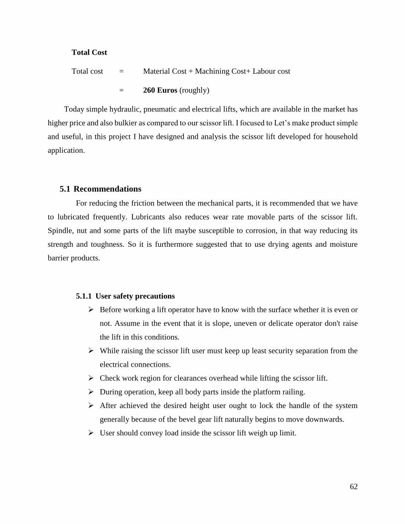
Table 5. 1 Product cost
Sl.
No. PARTS Material Qty.
Amount
(Euros)
1 Top platform Structural steel 1 30
2 Bottom platform Structural Steel 1 30
3 Bevel gear Gray Cast Iron 2 15
4 Lead Screw Stainless steel 1 20
5 Cross link Structural Steel 8 40
6 Racket Pawl Gray cast iron 1 10
7 Connecting link Stainless steel 3 20
8 Fasteners (Bolt and Nut) Stainless Steel 4 5
9 Bearing Stainless steel 3 15
10 Castor wheel setup Polypropylene 4 30
11 Total 29 215
Machining Cost (Drilling, Welding, Grinding,
Gas Cutting Cost, Punching etc.,) = 15 Euros
Labour cost = 30 Euros
If we purchase lift machineries (required specification) from the wholesale market
then doing assembly process, price will come about 245 Euros. While assembly process
supposed to machining process involved, it will take some additional amount for this
process. So total cost is,
62
Total Cost
Total cost = Material Cost + Machining Cost+ Labour cost
= 260 Euros (roughly)
Today simple hydraulic, pneumatic and electrical lifts, which are available in the market has
higher price and also bulkier as compared to our scissor lift. I focused to Let’s make product simple
and useful, in this project I have designed and analysis the scissor lift developed for household
application.
5.1 Recommendations
For reducing the friction between the mechanical parts, it is recommended that we have
to lubricated frequently. Lubricants also reduces wear rate movable parts of the scissor lift.
Spindle, nut and some parts of the lift maybe susceptible to corrosion, in that way reducing its
strength and toughness. So it is furthermore suggested that to use drying agents and moisture
barrier products.
5.1.1 User safety precautions
Before working a lift operator have to know with the surface whether it is even or
not. Assume in the event that it is slope, uneven or delicate operator don't raise
the lift in this conditions.
While raising the scissor lift user must keep up least security separation from the
electrical connections.
Check work region for clearances overhead while lifting the scissor lift.
During operation, keep all body parts inside the platform railing.
After achieved the desired height user ought to lock the handle of the system
generally because of the bevel gear lift naturally begins to move downwards.
User should convey load inside the scissor lift weigh up limit.
63
6. Conclusion
Strength conditions of structural elements of the model have been analyzed and the
optimal results have been achieved. The prime goal being analysis of strength of conditions of
structural elements, we have analyzed the scissor lift model and obtained favorable results. Apart
from this model being feasible, it also has various attributes that add to its value. In contrast to the
hydraulic lifts we use in our daily basis, our model consists of a mechanical drive. It paves the way
for many advantages:
Ease of use - Just one person will be required for operation. So, the person who
is using the lift can operate it by himself, whereas in traditional models, we
require an additional person for operation.
Weight - Absence of the hydraulic cylinder resulted in reduction of the weight
of the model. Our model can carry a net weight of 300 Kgs of load and can go
upto a height of 2.9 meters which are comparatively better results than the
existing models.
Storage Space - Requires very less space for storage and wage because our
model is foldable and its dimensions are very user friendly for a home purpose
usage.
Price factor – Our lift will be available for a price of around 250 euros, whereas
the existing lifts in the market are priced from a range of 350 to 600 euros
Maintenance – The operational costs and maintenance costs are very less
compared to the other lifts in the market
We are able to produce lifts at a less cost because it doesn’t involve any hydraulic (or) electrical
systems in it. Only mechanical technology benefits a lot in when it comes to the production costs.
To conclude, I strongly believe that apart from the design being successful, our scissor lift is also
a new approach to the market.
64
7. References
[1] [Online]. Available: https://en.wikipedia.org/wiki/Aerial_work_platform.
[2] "Vestil," Vestil Manufacturing Corp, [Online]. Available: http://www.vestilmfg.com/.
[3] Stanley and M. Oletu, "Scissor Lift design for use in the automotive industry," Wilberforce
Island, Amassoma, Bayelsa state, 2012.
[4] McElhaney, Leah, J. R, Smith, Gosse and Kayla, "Optimal design 5 report lift system to
ascend/descend stairs".
[5] K.G.Ghanashyam, B.H.Vasudevamurthy and A.K.Krishnapra, "Design, Development and
Analysis of Z-Axis Translation for an Earth Sensor Test Facility," International Journal of
Scientific and Research Publications, vol. 3, no. 7, July 2013.
[6] Ren, G.Dong, Christopher, S.Pan, Harts, J.Jared, Brumfield, Anne, Harris, R.James, John,
Wimer, Bryan, Mucino, Victor, Means and Kenneth, "An Investigation on the Dynamic
Stability of Scissor Lift," Open Journal of Safety Science and Technology, vol. 2, no. 15, p.
8, 2012.
[7] Heide, Bielefeld and Carsten, "Lift". United States Patent 4534544, 13 August 1985.
[8] Jeyangel, A.Roys, M.Babu and V.Balasubramani, "Design and kinematic analysis of gear
powered scissor lift," International Journal of Emerging Technology in Computer Science
& Electronics (IJETCSE), vol. 12, no. 3, January 2015.
[9] C. S.Dhamak, D.S.Bajaj and V.S.Aher, "Design and Optimization of Scissor Jack,"
International Journal of Advances in Production and Mechanical Engineering, vol. 2, no. 1,
2016.
[10] Hamidi and Beqir, "Design and calculation of the scissors-type Elevating Platforms,"
Kosovo.
65
[11] Udgirkar, G. Shashikant, Patil, M. Shantinath, Patil, R. Vijay, N. R. Chavan and P.
Panchbhai, "Design, Development and analysis of electrically operated toggle jack using
power of car battery," International Journal of Computational Engineering Research
(IJCER), vol. 4, no. 7, July 2014.
[12] Ganguly, Shameek, Garg, Akash, Pasricha, Akshay and S.K.Dwivedy, "Design and
fabrication of a novel three wheel robot with a SLE based lifting mechanism and line tracking
capability," in 14th National Conference on Machines and Mechanisms (NaCoMM-09), NIT,
Durgapur, India,, 2009.
[13] [Online]. Available: https://en.wikipedia.org/wiki/Aerial_work_platform.
[14] V.B.Bhandari, in Design of Machine Elements, p. 202.
[15] Dr.R.K.Bansal, Strength of Materials, New Delhi: Laxmi Publications (P) Ltd, 2009.
[16] "Course Hero," [Online]. Available:
https://www.coursehero.com/file/6785572/VonMisesCriterion/. [Accessed 2017].
[17] [Online]. Available: https://en.wikipedia.org/wiki/Von_Mises_yield_criterion.
[18] [Online]. Available: https://en.wikipedia.org/wiki/Structural_steel#cite_note-1.
[19] [Online]. Available: http://www.strucalc.com/engineering-resources/normal-stress-
bending-stress-shear-stress/.
[20] R.S.Khurmi and J.K.Gupta, in A Text book of Machine Design, New Delhi, Eurasia
Publishing house (Pvt.) Ltd., 2005.
[21] [Online]. Available: https://en.wikipedia.org/wiki/Ball_bearing.
[22] Dr.D.Padmanaban and Dr.M.Aruna, "Design Data," in Data book of Engineers, Coimbatore,
Tamil Nadu: Kalaikathir Achchagam, 1978, pp. 4.2 - 4.3.
[23] [Online]. Available:
http://www.engineersedge.com/thread_strength/thread_bolt_stress_area_iso.htm.
66
[24] "Creative Mechanisms," [Online]. Available:
https://www.creativemechanisms.com/ratchets.
[25] R. m. Jones, Deformation Theory of Plasticity, Bull Ridge Publishing, 2009.