Embed Size (px)
Citation preview
Yliopiston kampusalue
HYBRID EXCITATIONSYNCHRONOUS MACHINES
(HESMs)FOR ISLAND OPERATION
Katteden Kamiev Janne Nerg Juha Pyrhönen
CONTENTS
• Introduction • Classification• Mechanical Considerations• Radial Flux Machines• Example Machine• Finite Element Analysis• Conclusion• References
INTRODUCTION
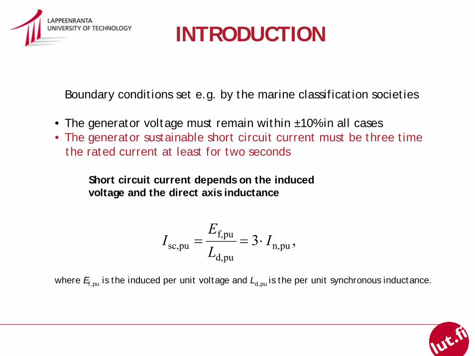
Boundary conditions set e.g. by the marine classification societies
• The generator voltage must remain within ±10% in all cases• The generator sustainable short circuit current must be three time
the rated current at least for two seconds
,3 pun,pud,
puf,pusc, I
LE
I ⋅==
Short circuit current depends on the induced voltage and the direct axis inductance
where Ef,pu is the induced per unit voltage and Ld,pu is the per unit synchronous inductance.
CLASSIFICATION of CLASSIFICATION of HESMsHESMs
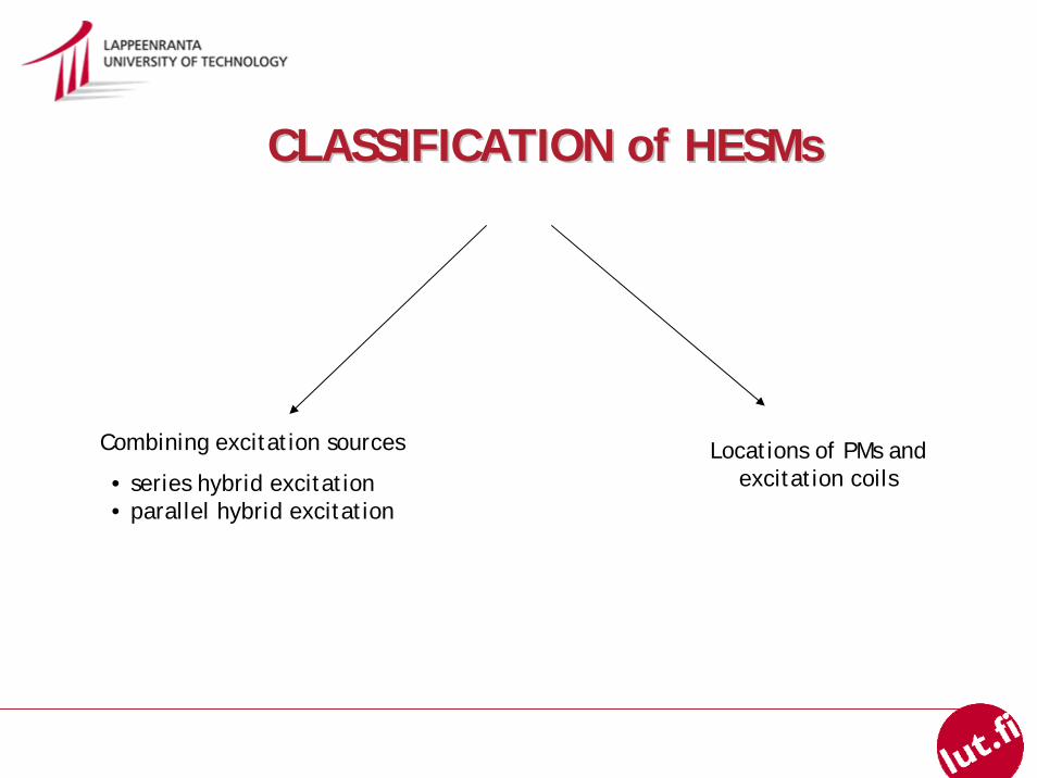
Locations of PMs and excitation coils
Combining excitation sources
• series hybrid excitation• parallel hybrid excitation
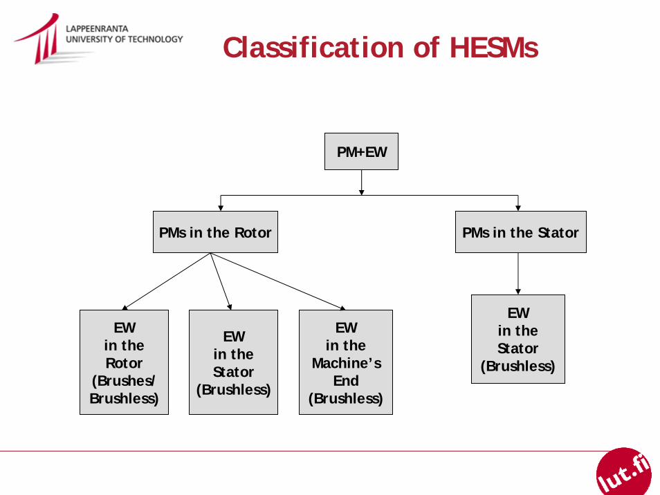
Classification of HESMs
PM+EW
PMs in the Rotor
EWin theRotor
(Brushes/Brushless)
PMs in the Stator
EWin theStator
(Brushless)
EWin the
Machine’sEnd
(Brushless)
EWin theStator
(Brushless)
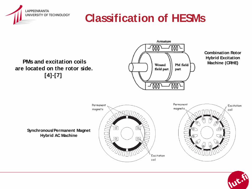
PMs and excitation coilsare located on the rotor side.
[4]-[7]
Classification of HESMs
Combination RotorHybrid ExcitationMachine (CRHE)
Synchronous/Permanent MagnetHybrid AC Machine
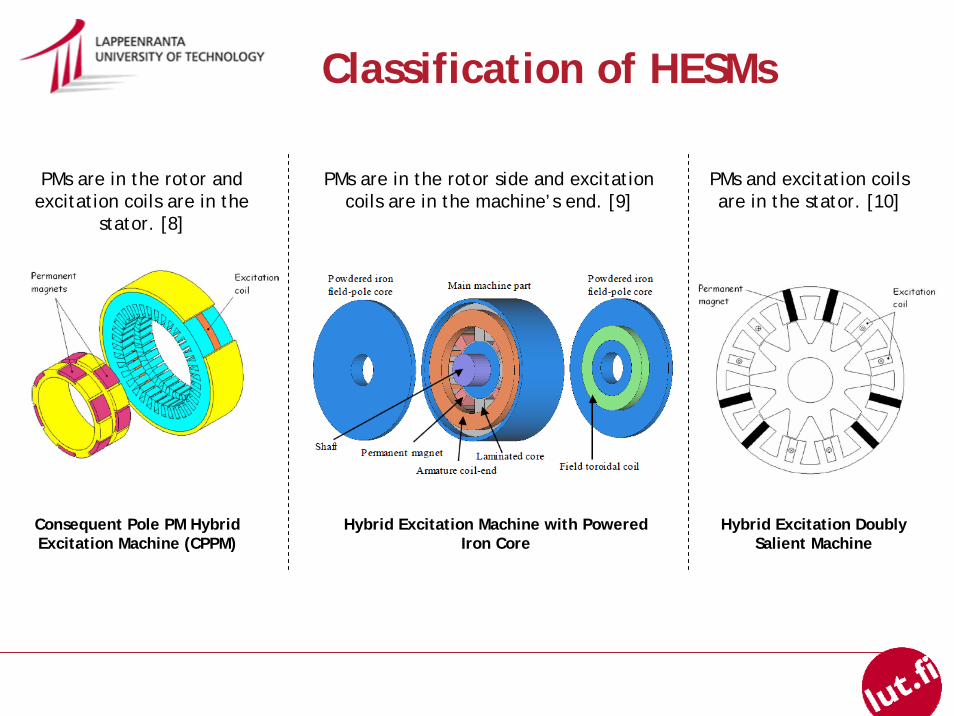
PMs are in the rotor and excitation coils are in the
stator. [8]
PMs are in the rotor side and excitation coils are in the machine’s end. [9]
PMs and excitation coils are in the stator. [10]
Classification of HESMs
Consequent Pole PM HybridExcitation Machine (CPPM)
Hybrid Excitation Machine with PoweredIron Core
Hybrid Excitation DoublySalient Machine
OperationOperation PrinciplePrinciple
SpecialSpecial FeaturesFeatures
ApplicationsApplications
• two excitation sources which can be connected either in series or in parallel
• location of PMs and excitation coils• bi-directional DC current
HESM has two excitation sources. One is the PM source that provides the air-gap with constant flux and the other one is the EW (DC current) that acts as the flux regulator to adjust the air gap flux distribution.
• as a generator it may be used inan island operation(alp, island, ship, etc.)
• as a motor HESM is attractive fortraction applications, for example,in electric, hybrid electric and fuel cell vehicles
Classification of HESMs
Mechanical Considerations
Advantages of radial flux vs. axial flux construction
• The rotor of a radial flux machine may be more rugged than the rotorof an axial flux machine
• Ideally, radial flux machine produces no axial forces• Radial flux machine is easier to cool as the rotor can in some cases
be built as hollow• Damper winding is easier to arrange in a radial flux machine• The radial flux rotor dimensions may easily be adjusted to produce
a suitable inertia for the prime mover
RadialRadial FluxFlux MachinesMachines
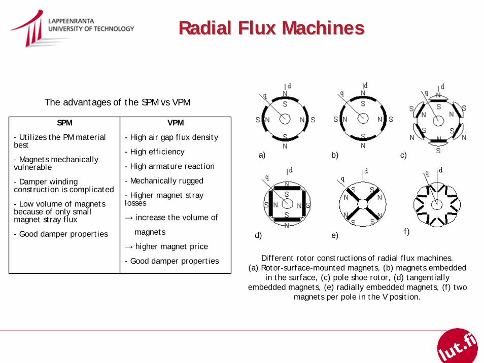
SPM
- Utilizes the PM material best
- Magnets mechanically vulnerable
- Damper winding construction is complicated
- Low volume of magnets because of only small magnet stray flux
- Good damper properties
VPM
- High air gap flux density
- High efficiency
- High armature reaction
- Mechanically rugged
- Higher magnet stray losses
→ increase the volume of
magnets
→ higher magnet price
- Good damper properties
a) b) c)
d) e) f)
The advantages of the SPM vs VPM
Different rotor constructions of radial flux machines.(a) Rotor-surface-mounted magnets, (b) magnets embedded
in the surface, (c) pole shoe rotor, (d) tangentially embedded magnets, (e) radially embedded magnets, (f) two
magnets per pole in the V position.
EXAMPLE MACHINE
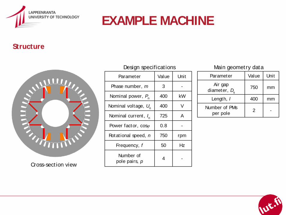
StructureStructure
Parameter Value Unit
Phase number, m 3 -
Nominal power, Pn 400 kW
Nominal voltage, Un 400 V
Nominal current, In 725 A
Power factor, cosφ 0.8 -
Rotational speed, n 750 rpm
Frequency, f 50 Hz
Number of pole pairs, p 4 -
Parameter Value Unit
Air gapdiameter, Ds
750 mm
Length, l 400 mm
Number of PMsper pole
2 -
Design specifications Main geometry data
Cross-section view
EXAMPLE MACHINE
OperationOperation PrincipalPrincipal
EWPM
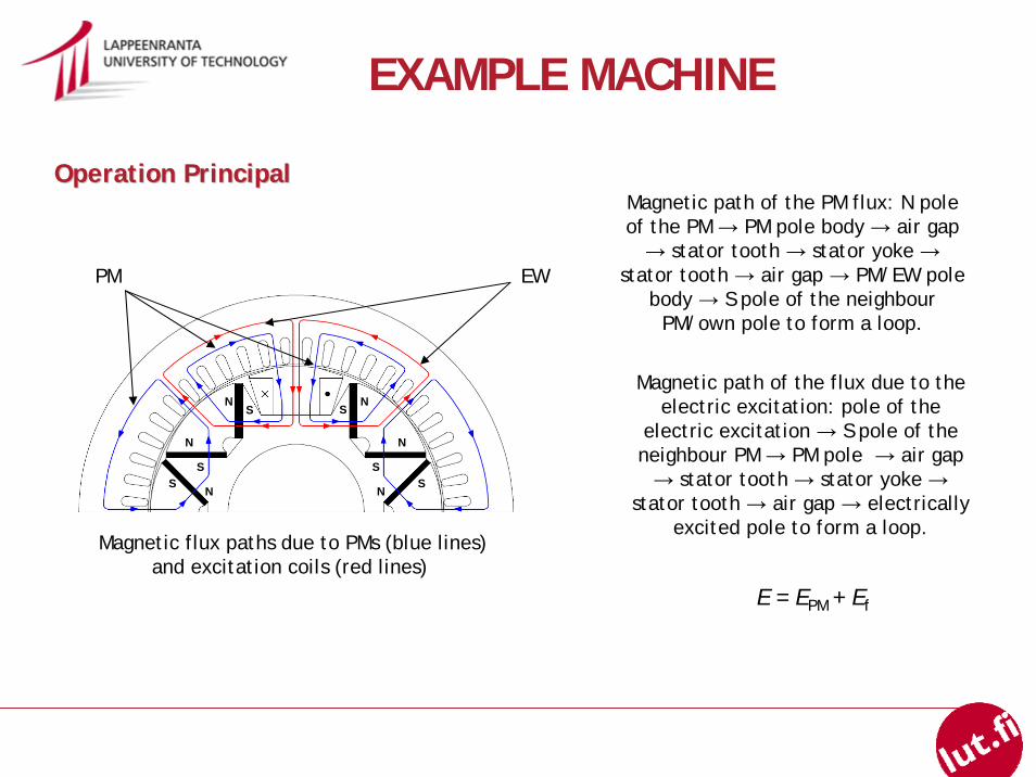
Magnetic flux paths due to PMs (blue lines)and excitation coils (red lines)
NS
NS
N
SS
N
SN
N
S
Magnetic path of the PM flux: N pole of the PM → PM pole body → air gap → stator tooth → stator yoke →
stator tooth → air gap → PM/EW pole body → S pole of the neighbour
PM/own pole to form a loop.
Magnetic path of the flux due to the electric excitation: pole of the
electric excitation → S pole of the neighbour PM → PM pole → air gap → stator tooth → stator yoke →
stator tooth → air gap → electrically excited pole to form a loop.
E = EPM + Ef
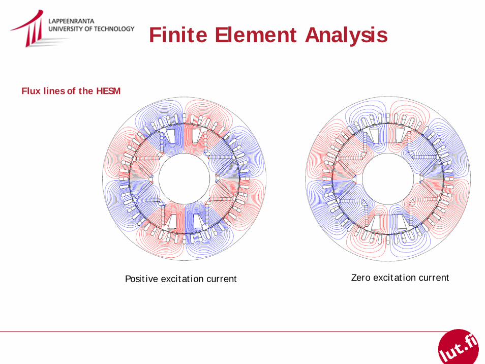
Finite Element Analysis
Flux lines of the HESM
Positive excitation current Zero excitation current
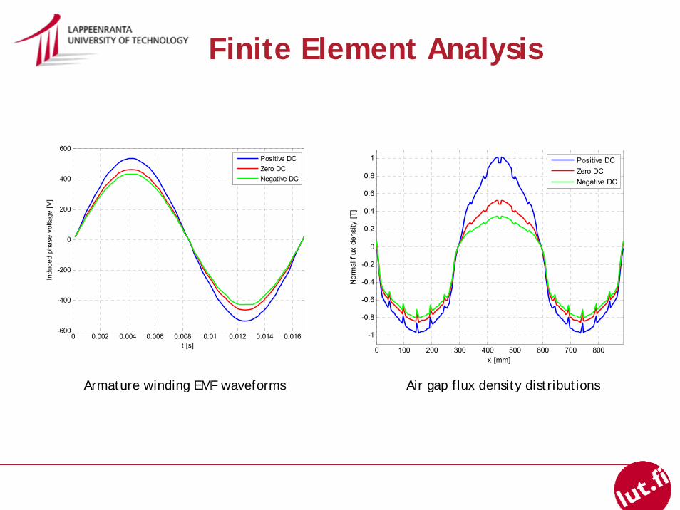
Armature winding EMF waveforms
0 100 200 300 400 500 600 700 800
-1
-0.8
-0.6
-0.4
-0.2
0
0.2
0.4
0.6
0.8
1
x [mm]N
orm
al fl
ux d
ensi
ty [T
]
Positive DCZero DCNegative DC
Air gap flux density distributions
0 0.002 0.004 0.006 0.008 0.01 0.012 0.014 0.016-600
-400
-200
0
200
400
600
t [s]
Indu
ced
phas
e vo
ltage
[V]
Positive DCZero DCNegative DC
Finite Element Analysis
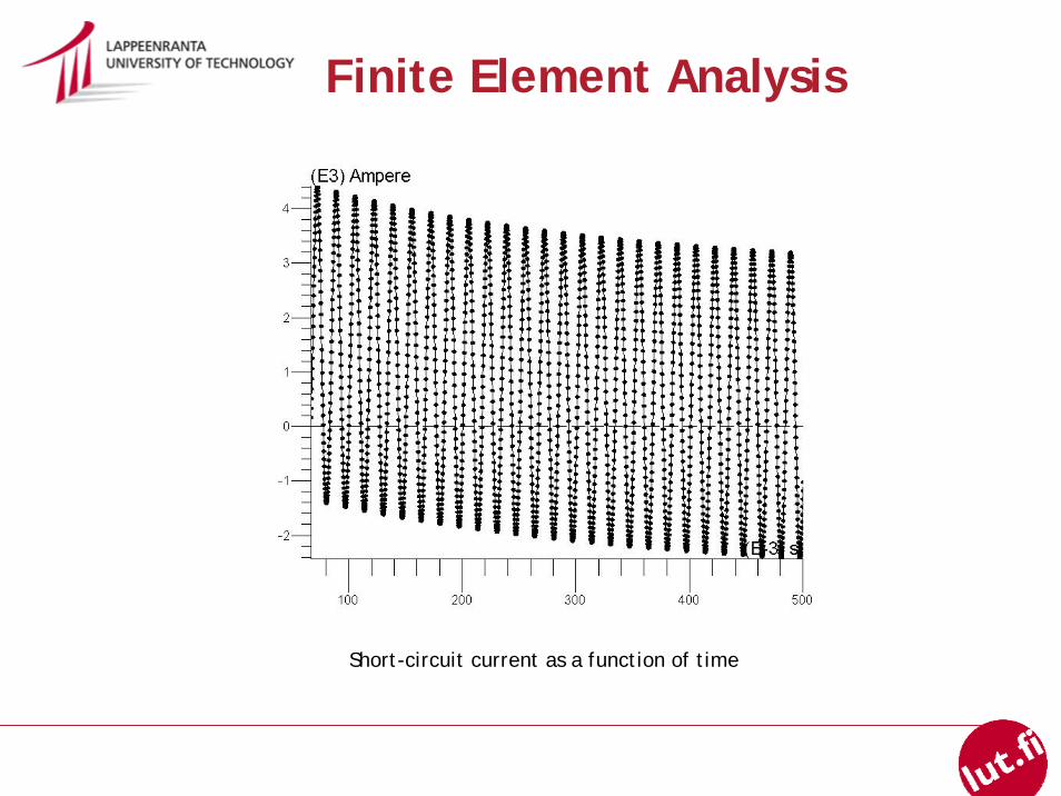
Short-circuit current as a function of time
Finite Element Analysis
CONCLUSION
- combine advantages of PM machines andtraditional synchronous machines
- have different constructions
- have good flux control capability
- can increase the short-circuit current
HESMs
REFERENCES
[1]. Hybrid Excitation Synchronous Machines: Energy-Efficient Solution for Vehicles PropulsionAmara, Y.; Vido, L.; Gabsi, M.; Hoang, E.; Hamid Ben Ahmed, A.; Lecrivain, M.; Vehicular Technology, IEEE Transactions on Volume 58, Issue 5, Jun 2009 Page(s):2137 - 2149 Digital Object Identifier 10.1109/TVT.2008.2009306
[2]. Direct control of air-gap flux in permanent-magnet machinesJ. S. Hsu, IEEE Trans. Energy Convers., vol. 15, no. 4, pp. 361–365,Dec. 2000.
[3]. A new axial flux surface mounted permanent magnet machine capable of field controlM. Aydin, S. Huang, and T. A. Lipo, in Conf. Rec. IEEEIAS Annu. Meeting, 2002, vol. 2, pp. 1250–1257.
[4]. A synchronous/permanent magnet hybrid AC machineXiaogang Luo; Lipo, T.A.;Energy Conversion, IEEE Transaction on Volume 15, Issue 2, June 2000 Page(s):203 - 210 Digital Object Identifier 10.1109/60.867001
[5]. Trial production of a hybrid excitation type synchronous machineN. Naoe and T. Fukami,Electric Machines and Drives Conference, 2001. IEMDC 2001.IEEE International, pp. 545-547,2001.
REFERENCES
[6]. Design and test of permanent magnet synchronous motor with auxiliary excitationwinding for electric vehicle applicationG. Henneberger, J. R. Hadji-Minaglou, and R. C. CiorbaProc. Eur. Power Electron. Chapter Symp., Lausanne, Switzerland,Oct. 1994, pp. 645–649.
[7]. A double excited synchronous machine for direct drive application - Design and prototype testsD. Fodorean, A. Djerdir, I. A. Viorel, and A. Miraoui,IEEE Trans. Energy Convers., vol. 22, no. 3, pp. 656–665, Sep. 2007.
[8]. Consequent-pole permanent-magnet machine with extended field-weakening capabilityTapia, J.A.; Leonardi, F.; Lipo, T.A.;Industry Applications, IEEE Transactions onVolume 39, Issue 6, Nov.-Dec. 2003 Page(s):1704 - 1709 Digital Object Identifier 10.1109/TIA.2003.818993
[9]. Hybrid excitation machines with powdered iron core for electrical traction drive applicationsKosaka, T.; Matsui, N.;Electrical Machines and Systems, 2008. ICEMS 2008. International Conference on 17-20 Oct. 2008 Page(s):2974 – 2979
[10]. Static characteristics of a novel hybrid excitation doubly salient machineChen Zhihui; Sun Yaping; Yan Yangguang;Electrical Machines and Systems, 2005. ICEMS 2005. Proceedings of the Eighth International Conference on Volume 1, 27-29 Sept. 2005 Page(s):718 - 721 Vol. 1

THANK YOU!