Embed Size (px)
DESCRIPTION
Masters of Architecture Student AP Design | Kasas State University
Citation preview
Katherine Gallagher


Katherine Gallagher
207 birchleaf drivest. peters, mo 63376
636.578.7672
An evolutionary document
CollectiveWorks
the


design
spaces
that
people
want
to
be
in.
My drive to become an Architect started even before I can remember. Who knew that the career decision written on wide ruled paper in Kindergarten was going to become my passion. In the past five year of school studying design, I have learned many things. Ultimately I find myself driven by three main philosophies. The connection with the site and surrounding environment. The inhabitants of spaces and their ability to positively interact with the built form and the structure in which the bulding rests. You will find at some level each of these philosopies carried out in everyone of my designed works. As a personal philosophy that pours into my passion for Architecture, I believe in working as hard as you can and pushing oneself to achieve more.
“The thing always happens that you really believe in; and the belief in a thing makes it happen.” - Frank Llyod Wright
Philosophy


Katherine Gallagher
table of contents
Sustainable Community*
Gateway Winery
CiCo Park Natatorium
Undulating Facade
Economic Assistance Center
Gravity Beer House
A Model for Intergenerational Living
A Compliment to the Konza Prairie
A Design from the Earth for the Seasons
A Study in Precast Concrete
A Design for Humanity
A Design for Sustainability
*in process
Denver International Airport
San Francisco 49er’s Stadium
Artistic GalleryA Predesign Necessity
A Design Build Pace
A Snapshot of Me
Discovery Implementation Production


An impowering learning experience
DiscoverySection
the

Designing a new building type. Integrating innovative materials and technology. Promoting social interaction through design. Creating a sustainable future.
SITE
FUNCTION
OPPORTUNITIES
Residential street in Downtown Zurich, Switzerland
Create a living environment that responds to the growing elderly population with a socially sustainable, environmentally conscious idea.
A Model for Intergenerational Living
SustainableCommunity
the

Intergenerational living can be defined as multiple generations of people intermingled or coming together in a housing environment. Although there are many neighborhoods, apartment complexes, and public housing projects that have multiple generations in a similar area, there has not been a building type that specifically addresses the growing needs of the aging population as it relates to the younger generations in housing. Charged with the task of designing this new living environment, an urban site in Zurich, Switzerland was chosen for the study. A three-parcel site with three separate existing apartment buildings makes up the buildable area. The site is located on a one-way, quiet street with close proximity to major public transportation and many amenities. The environmental considerations are specific to Zurich but the social considerations can be used as a model. The design proposal calls for residential living arrangements of varying types for all ages. Units designed for families, singles, and cooperative living, with shared communal spaces makes up the intergenerational model for approximately 90 residents. The key is promoting the interaction of all generations.
DESIGN

Street Elevation

BUILDING SCALE
SITE SCALE
BUILDING SCALE
UNIT SCALEUNIT SCALE
Levels of Community

second levelground level
Longitudinal Section through circulation

third level forth level
Back Elevation

Honoring the beauty of the pristine prairie. Integrating the building to minimize cooling loads. Redesigning the scenic overlook. Allow for functional access to the building. Create a memorable façade for the Konza’s research effort throughout the Prairie.
SITE
FUNCTION
OPPORTUNITIES
Located in the Konza Prairie on the site of a current scenic overlook.
Provide a location for a research oriented wine making facility that allows for an interactive visitor experience.
A Complement to the Konza
GatewayWinery
the

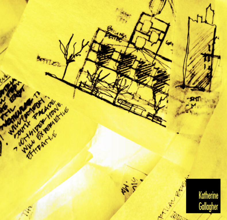
The Konza Prairie is a pristine landscape of strong presence, filled with rolling hills and expansive views. The design challenge is to establish a complementary relationship between the opposing industrial process and the untouched wilderness. Inspired by this landscape I sought to capture the essence of the tall grass and sweeping expanses of the Konza. The concept stems straight from the Konza itself in an attempt to complement and frame its beauty while seamlessly integrating the program. The silhouette of the façade emulates the surrounding topography while the perforated corten steel begins to intrigue the visitor. The integration of the wine making process allows visitors to enrich their knowledge of the Konza while tasting the beauty of the land. The Gateway Winery is not only a building in a landscape, it is a building that complements and symbolizes the landscape of the Konza Prairie.
DESIGN
WINE PEOPLE
KONZAPRAIRIE

fermentation
tasting
aging
bottling
fermentationbottling
shipping
shipping
overlook
interior view of the fermentation tanks
exterior view looking into the aging cave
lower level_aging, fermentation, bottling
ground level_overlook, tasting
front facade

transverse section


9’
#
o
o
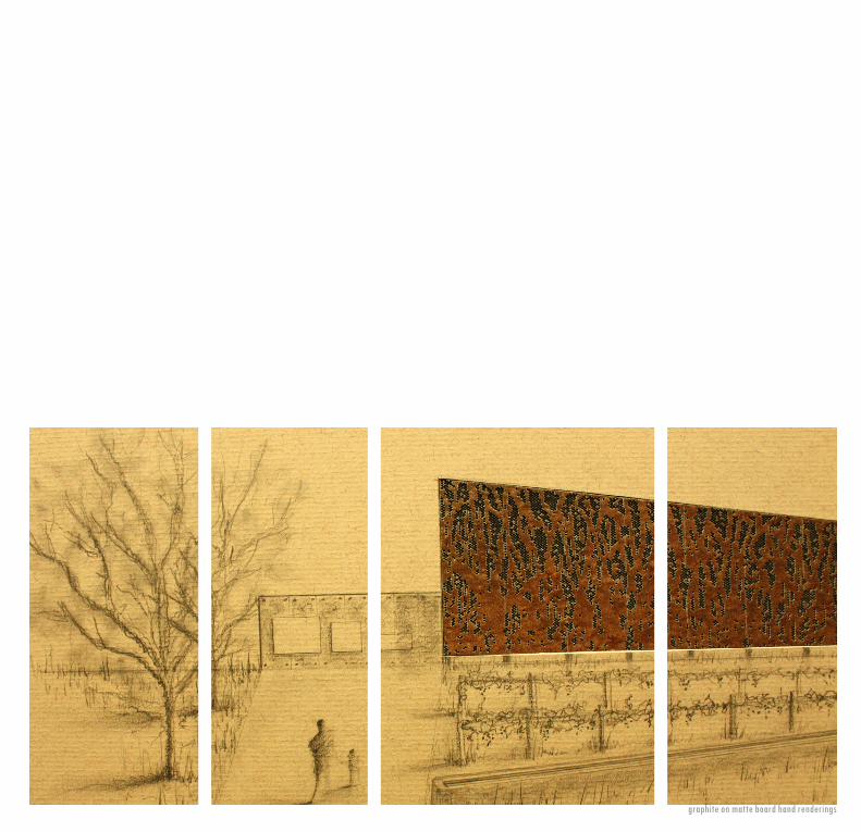
graphite on matte board hand renderings


Utilize a steep sloping landscape to form strong site relationships. Design an operable building which can easily adapt to all seasons. Discover the meaning of tectonics and integrate into design
SITE
FUNCTION
OPPORTUNITIES
Located in the Cico Park area of Manhattan, KS
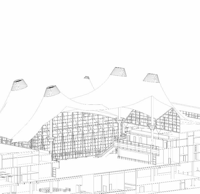
Serve as a year round swimming facility, more specifically competitive swimming and diving.
A Design from the Earth for the Seasons
CiCo ParkNatatorium
the

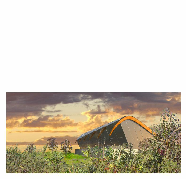
After surveying CiCo Park one would notice the strong relationship to surrounding landscape of the rolling Flint Hills. By utilizing these hills as a dynamic base for a natatorium I was able to create a structure that seemingly emerged from the landscape. The arched form is one that is found in the movement of water and directly reflects the use of the natatorium. In order to create such a strong form the implementation of large structural glue lam beams gave the building its materiality. The building becomes even more dynamic with the design of a retractable roof structure that gave the pool flexibility in all seasons. Understanding how the earth and the building relate was the beginning of tectonic design integration for the natatorium.
DESIGN

ground floor plan
LAP POOLDIVING WELL
Techtonics
Form
Structure
Earth
longitudinal section

looking up from the valley
arial view of model arial view of roof interior shot of diving well


image of full scal mock up
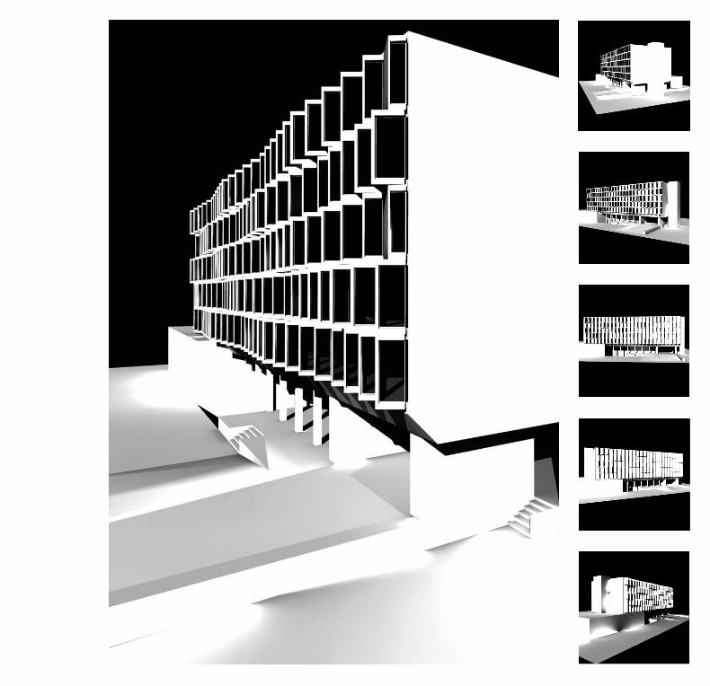
The proximity of Manhattan’s Holiday Inn to the KSU campus makes its appearance an important aesthetic of the University. With that said, the 1970’s façade needs a facelift. Me and two other classmates designed, detailed and built a newly refurbished skin to be attached to the current core of the building. The main design intent was to facilitate views onto campus, provide adequate sun shading and create visual interest. By producing a precast modular system, the dynamic façade could be produced at a relatively low cost and potentially replicated on many applications.
SITE
FUNCTION
DESIGN
Holiday Inn Manhattan, KS
Renovation of building skin design.
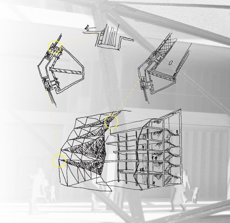
A Study in Precast Concrete
UndulatingFacade
the

assembly detail section detail
SECTION DETAIL
ASSEMBLY DIAGRAM
WINDOW DETAIL
1
2
3
UNDULATING FACADEA STUDY IN PRECAST CONCRETECHILLIN’ AT THE HOLIDAY INNKATIE GALLAGHERASHLEY SIMPSONRYAN WILSON
SECTION DETAIL
ASSEMBLY DIAGRAM
WINDOW DETAIL
1
2
3
UNDULATING FACADEA STUDY IN PRECAST CONCRETECHILLIN’ AT THE HOLIDAY INNKATIE GALLAGHERASHLEY SIMPSONRYAN WILSON
SECTION DETAIL
ASSEMBLY DIAGRAM
WINDOW DETAIL
1
2
3
UNDULATING FACADEA STUDY IN PRECAST CONCRETECHILLIN’ AT THE HOLIDAY INNKATIE GALLAGHERASHLEY SIMPSONRYAN WILSON
front building elevation _modular placement diagram

SECTION DETAIL
ASSEMBLY DIAGRAM
WINDOW DETAIL
1
2
3
UNDULATING FACADEA STUDY IN PRECAST CONCRETECHILLIN’ AT THE HOLIDAY INNKATIE GALLAGHERASHLEY SIMPSONRYAN WILSON
wall section wall elevation
SECTION DETAIL
ASSEMBLY DIAGRAM
WINDOW DETAIL
1
2
3
UNDULATING FACADEA STUDY IN PRECAST CONCRETECHILLIN’ AT THE HOLIDAY INNKATIE GALLAGHERASHLEY SIMPSONRYAN WILSON

Bring value back to what is now referred to as the “donut” of Denver’s CBD. Create a facility that is flexible in its use while also creating an icon in the community. Design sustainably to decrease heating and cooling loads. Collaborate with a Landscape Architects adjacent outdoor space.
SITE
FUNCTION
OPPORTUNITIES
Located in Downtown Denver’s Arapahoe Square district.
Serve as an outlet for Denver’s large number of financially burdened people to find work, learn skills, and rise out of poverty.
A Design for HumanityCenter
EconomicAssistance
the

Arapahoe Square is an area of Downtown Denver that has been seriously neglected because of the large number of homeless people who fill its streets and parks. The area desperately needed a place the community could take pride in, a place to call their home. The prime location for the site for the Downtown Economic Center is at the convergence of three main urban conditions. The proximity to subsidized housing units, a public transportation outlet and dense retail job sustainability all combine to inform the site placement. The main design parti focused on the environmental considerations, the spatial considerations, and the circulation considerations. As each of these three design goals were addressed they created an integral scheme that influenced my buildings form and organization. In an attempt to unite a ravished community, the design parti reaches out and symbolizes the steep journey of those inside.
DESIGN
FunctionalSocial
Environmental
Sun
WindViews
Parti

exterior view of the fifth floor overlook
interior view of the third floor study lounge
interior view of the cafe and shopfirst floor_cafe and retail shop
second floor_financial counceling services
third floor_technical classrooms
fourth floor_technical classrooms
fifth floor_financial planning
sixth floor_administration and hiring

entrance through landscape architect, natalie martell’s outdoor space


A Design for SustainabilityHouse
GravityBeer
the
Designing in a urban setting with many different surrounding functions. Incorporating the production of beer as an experiential part of the building. Produce a set of Construction Documents. Test the building per LEED standards.
SITE
FUNCTION
OPP0RTUNITIES
Located in Downtown Kansas City, MO.
Provide a brewery for Downtown KC’s Power and Light District that produces the product on sight.

Located in Downtown Kansas City, in the lively Power and Light District, is the site for a new Brewing Company. This sites context is extremely diverse and poses a few difficult challenges while also allowing for some environmental design solutions. The main contextual concerns are how to relate to the diverse building typology and forms created surrounding the immediate site, while still creating a dynamic destination for residents and tourists alike. With that said, the need for a building that reacts to the scale of the surrounding buildings informed the idea for a vertical brewing process. By creating a vertical process there are many benefits. Aesthetically, the building becomes the process. The building creates a diagram of the process to add to the experience of enjoying an ice cold brewsky. Functionally, a vertical process greatly decreases the need for mechanical pumping systems and therefore minimizes the potential for any mechanical failures. Environmentally, the form of the process allows for the greatest potential for photovoltaic usage, while allowing maximum sunlight and added stack ventilation. Also, by using gravity--which is free and not harmful to the environment--there is a more responsible building created. The main goal of the vertical brewing process is to inform its consumers of how the beer is made while being a dynamic backdrop for the enjoyment of the city.
DESIGN

GRAIN
MASH TUN
BOILING KETTLE
FERMENTATION
BOTTLING
structure diagram
ground floor_bottling, shipping
second floor_hospitality
third floor_fermentation
fourth floor_boiling kettle, lauter tun
fifth floor_mash tun
roof plan_grain silo
steel concrete


Fermentation27' - 0"
Argon Empregnated Air SpaceCurtain Wall System
Sealant and Backer Rod
EPDM Roof Membrane
Sheet Metal FlashingSlope to Drain Roof Side
45° Pretreated Wood Cant
3" Polystyrene Insulation
Vapor Barrier
Vegetated Roof System Neoprene Washer
3/8" GalvanizedExpansion Bolts
19 Gauge7/8" Corregated CortenSecured as Needed
1-1/2" CorregatedMetal Deck
6" Lightweight Concrete
Steel Pedistal System24" O.C. Grid
4" Polystyrene Insulation
Sealant Over PedistalsVapor Barrier
Roof MembranePhotovoltaic Roof System
19 Gauge 7/8" CorregatedCorten RainscreenReinforcing Rebar
Site Cast ConcreteShear Wall
4" Polystyrene Insulation
Steel Channel Fasteners
Expansion Bolts
Steel Angle Embed w/Steel Stud Anchors
0' - 1 1/2"
0' - 1 1/2"
19 Gauge 7/8" Corregated Corten Rainscreen
Aluminum Welded to Back FrameAluminum Bent Chanel Back Frame
Aluminum Bent Channel Carrer TrackExpansion Bolt
Aluminum Bent Metal Bracket
BoltNeoprene Thermal Washer
Fermentation27' - 0"
Sedum Plantings
Aluminum Flashing DetailOver Roof Membrane
EPDM Roof MembraneDrainage MatFilter Fabric
45° Pretreated Wood Cant
3" Polystyrene Insulation
Reinforcing Steel Rebar
4" Waffle Slab Cover
12" Ø Slope
Aluminum and Plastic Sealant
Vapor Barrier
Argon Empregnated Air SpaceAluminum Skylight Casing
Polycarbonate Skylight w/1" Edge Conditions
3" Engineered Growing Media
0' -
9 3/
4"
1' -
0 1/
4"
0' - 6"
Fermentation27' - 0"
Aluminum Flashing Detail
Curtain Wall ConnectionVapor Barrier
Curtain Wall Tie Back AngleEPDM Roof Membrane
Expansion Bolt
4" Extruded Polystyrene Insulation
5" Site Cast Parapet
Wood Blocking
Waffle SlabVegatative Roof
Glass Panel1/4" Tempered Glass
Argon Empregnated Air Space1/4" Tempered Glass (UV -2)
2mm Perferated Aluminum1/4" Tempered Glass
transverse section axonmetric
skylight detail
greef roof parapet detailphotovoltaic roof detail
curtain wall detail

view walking from power and light district view of interior exposed steel structure view of interior hospitality space
view looking down from the mash tun


An eye opening addition
ImplementationSection
the

FUNCTION
SITELocated in Denver, Colorado
A Predesign NecessityAirport
Denver International
the
HNTB was contracted to model the existing DIA terminal that that will accept the new expansion. A small team of modelers were in charge of completing this task to a 300 Level of Detail. I modeled many families as well as helped to coordinate the team to complete different areas of the building. In the future DIA wants to model the remainder of the airport to use for facilities management.
OPPERTUNITIES
Help to coordinate terminal expansion and BIM modeling clash detection.

longitudinal section through atrium
trasnsverse section through atriumcoordination diagram

railing family for oversized luggage carousel column family for roof signage and tent support
interior view of a mechanical room

I was first introduced to the San Francisco 49er’s project during the schematic design phase. During the SD phase I worked on the designing, modeling and detailing the green roof and roof buildings. This allowed me to gain crucial knowledge of the design and helped to inform my further work on the core/shell modeling team. I worked as one of the leaders to complete the core/shell construction documents package. I focused my efforts by first improving the Revit modeling, then using the model to produce quality elevations, sections and details.
SITEConstructing in Santa Clara, California
68,500 seat NFL stadium with the capacity to expand to 75,000 for other large sporting events.
A Design Build PaceStadium
San Francisco49er’s
the
FUNCTION
OPPORTUNITIES


100 LEVEL FIELD10' - 6"
300 LEVEL MAINCONCOURSE
47' - 0"
200 LEVEL PLAZA24' - 0"
400 BROADCAST CLUBMEZZANINE
75' - 9"
500 LEVEL SUITE 1AND PREMIUM
AMENITIES93' - 9"
600 LEVEL SUITE 2107' - 0"
700 LEVEL SUITE 3120' - 3"
800 LEVEL PRESS136' - 3"
G.1H.1
900 LEVEL TOWERPLATFORM155' - 2 1/2"
MECH01.46.10
MEN03.44.02
WOMEN04.44.01
PANTRY05.42.09
SUPPORTPANTRY07.42.09
PRESS BOXSUPPORT08.44.04
STRUCTURAL STEEL FRAMINGREF: STRUCT
051200.A0
SPRAY-APPLIED FIREPROOFING078100.A0
GRAPHIC PANELRE: A310
18' -
11
1/2"
16' -
0"
13' -
3"
13' -
3"
18' -
0"
28' -
9"
23' -
0"
13' -
6"
A6A761.7
THERMAL INSULATION072100.A0
FIBER-REINFORCEDCEMENTITIOUS PANEL RAINSCREEN SYSTEM
074450.A0
2 HR RATED SHAFTENCLOSURERE: PLANS
H.2 H.8
1" MINERAL-FIBER ACOUSTICALBATT INSULATION PINNED TODECK
072100.A4
SELF-ADHERING SHEETWATERPROOFING MEMBRANESYSTEM
071326.A1
SUBSURFACE DRAINAGEPERFORATED PVC PIPE SEE CIVIL DWGS
T.O. PARAPET EL.177' - 9"
A606N1
B.O. METAL PANEL173' - 5"
T.O. COPING EL.165' - 3 1/2"
4' - 4
"8'
- 1 3
/4"
10' -
0 3
/4"
OVER
ALL
BUIL
DING
HEI
GHT
167'
- 3"
A605A1
SUPPORTPANTRY06.44.03
A311G1A605
D1
CONCRETE ENCASEMENT
A311G10
HIGH-PERFORMANCE COATINGREF: FIN SCHED
099600.A0
FORMED METAL WALL PANELLOUVER BLADES @ 24" OCVERTICAL
089119.B2
FORMED METAL WALL PANEL074213.13.A2
FIXED LOUVER089119.A0
A604N1
A604E1
A604A1
A605A13
PV PANEL ARRAY SUPPORTFRAMING
055000.S1
B C
D.1
E.1 F
A
6R @
11.
5"
5' - 9
"
6R @
11"
5' - 6
"
6R @
10.
5"
5' - 3
"
6R @
10"
5' - 0
"
3R @
9"
2' - 3
"2'
- 3"
4' - 6
"
13 R
ISER
S @
1'-4
"
17' -
4"
1' - 7
"9'
- 10"
8"
8" 7' - 10" 3' - 5"
32 TREADS @ 2'-9"
88' - 0" 6' - 9"
BEV DISTCOOLER01.44.06VISIT SHWR
01.43.03
SUITE05.43.02
SUITE06.43.02
SUITE07.43.02
NATIONALRADIO
08.43.03
MEN07.43.03
MEN06.43.03
MEN05.43.03
034100.A1PRECAST CONCRETE TREAD &
RISER REF: STRUCT
VIDEO RIBBON BOARD270000.D2
PIPE AND TUBE RAILINGS055213.A0
STADIUM SEAT126100.A1
STADIUM SEAT126100.A1
3' - 0"
12 TREADS @ 2'-9"
33' - 0" 14' - 9"
PIPE AND TUBE RAILINGS055213.A0
CAST-IN-PLACE CONCRETE SLABON GRADE
033000.A4STRUCTURAL STEEL FRAMINGREF: STRUCT
051200.A0
SPRAY-APPLIED FIREPROOFING078100.A0
PRECAST CONCRETE TREAD &RISER REF: STRUCT
034100.A1
TYP. @ LVLS 500-700
R-30 MINERAL-FIBER BOARDINSULATION
072100.A6
SERVICECORRIDOR
01.45.06VISITORLOCKERROOM
01.42.01
LAVS01.44.01VOID SPACE
4' - 0
"
COLUMN GUARDS
A423F1
FIBER-REINFORCEDCEMENTITIOUS PANEL RAIN
SCREEN SYSTEM
074450.A0
CORRIDOR08.42.04
MOTORIZED OPERABLE GLAZINGSYSTEM
085250.A1
R-30 MINERAL-FIBER BOARDINSULATION
072100.A6
R-30 MINERAL-FIBER BOARDINSULATION
072100.A6
CAST-IN-PLACE CONCRETE033000.A0
PLANNORTH
TRUENORTH
NN
Copyright © HNTB 2012
23456789101112131415
A
B
C
D
E
F
G
H
J
K
L
M
N
P
Q
R
DRAWN BYPROJECT NO.
CHECKED BYAPPROVED BY
DATEISSUEDFOR:
...
...
...
SHEET TITLE & NUMBER
Howard, Needles, Tammen &Bergendoff California Architects, P.C.
One Bunker Hill601 West Fifth Street, Suite 1000Los Angeles, California 90071(213) 403-1000 / Fax (213) 403-1001
1
Magnusson Klemencic Associates - StructuralEngineers
1301 Fifth Avenue, Suite 3200Seattle, WA 98101Ph: ( 206 ) - 292 - 1200Fax: ( 206 ) - 292 - 1201
Gutteridge Haskins & Davey - Civil Engineers
417 Montgomery Street, Suite 700San Francisco, CA 94104Ph: ( 415 ) - 283 - 4970Fax: ( 415 ) - 283 - 4980
Wrightson, Johnson, Haddon & Williams, Inc. - AV
4801 Spring Valley Road, Suite 113Dallas, TX 75244Ph: ( 972 ) - 934 - 3700Fax: ( 415 ) - 934 - 3720
FP & C Consultants, Inc. -Life Safety / Code Consultants
3770 BroadwayKansas City, MO 64111Ph: ( 816 ) - 931 - 8219Fax: ( 816 ) - 931 - 3378
DVV Associates - Curtain Wall
3902 West Cresthaven DriveWestlake Village, CA 91362Ph: ( 805 ) - 778 - 0802Fax: ( 805 ) - 778 - 0804
The Guzzardo Partnership, Inc. - Landscape
181 Greenwich StreetSan Francisco, CA 94111Ph: ( 415 ) - 433 - 4672
Persohn Hahn - Vertical Transportation
32696 Sandpiper DriveOrange Beach, AL 94133Ph: ( 713 ) - 467 - 4440Fax: ( 251 ) - 980 - 2883
Debra Nichols Design - Signage & Graphics
468 Jackson StreetSan Francisco, CA 94111Ph: ( 415 ) - 249 - 4657
7349, N. Via Paseo Del Sur, Suite 515-324Scottsdale, AZ 85258-3749Ph: ( 602 ) - 635 - 4226
Lloyd Consulting Group - Turf Consultant
C B
D A
PRELIMINARY NOT FOR CONSTRUCTION
4900
Cen
tenn
ial B
lvd.
San
ta C
lara
, CA
950
54-1
229
7/26
/201
2 3:
15:1
9 P
M
BUILDING SECTION
A408
58059
ARCHITECTURAL PERMIT SET
NEW
SAN
TA C
LAR
AS
TAD
IUM
07/30/2012
1/8" = 1'-0"
A1BUILDING SECTION WEST0 8' 16'4'
A
A
A
# DATE DESCRIPTION
A 03/01/2012 PROGRESS PRINT

200 LEVEL PLAZA24' - 0"
INSULATED METAL WALL PANELSYSTEM
074213.19.A1
FIBER-REINFORCEDCEMENTITIOUS PANEL RAINSCREEN SYSTEM
074450.A0
SLOPE
EXTRUDED FURRING CHANNEL074213.23.B2
JOINT SEALANT079200.A2
BOND BREAKER TAPE079200.B1
SEALANT W/ BACKER ROD079200.A1
SELF-ADHERING SHEETWATERPROOFING MEMBRANESYSTEM
071326.A1
WATERPROOFING ANDDRAINBOARD
CAST-IN-PLACE CONCRETE SLABW/ METAL DECKING
033000.D1
HAT-SHAPED FURRING CHANNEL074213.13.B1
A605P13
1"
H.1
TYP.
1' - 0
"5"
T.O. RAINSCREEN36' - 0"1/2"
EXTRUDED FURRING CHANNEL074213.23.B2
EXTRUDED FURRING CHANNEL074213.23.B2
EXTRUDED FURRING CHANNEL074213.23.B2
FORMED METAL WALL PANEL074213.13.A2
PREFINISHED SHEET METALCLOSURE
076200.E1
8" STRUCTURAL METAL STUD054000.A10
5/8" TYPE "X" GYPSUM BOARD092900.D1
FIBER-REINFORCEDCEMENTITIOUS PANEL RAINSCREEN SYSTEM
074450.A0
600 LEVEL SUITE 2107' - 0"
H.1
STEEL BEAM REF: STRUCT051200.A2
EXTRUDED FURRING CHANNEL074213.23.B2
2-HR CONCEALEDSPRAY-APPLIED FIREPROOFING
078100.A2
INSULATED METAL WALL PANELSYSTEM
074213.19.A1
8" STRUCTURAL METAL STUD054000.A10
STRUCTURAL METAL STUDDEFLECTION TRACK
054000.H1
EDGE OF SLAB ANGLE051200.A5
FORMED METAL WALL PANEL074213.13.A2
2-PIECE DEFLECTION FLASHING074213.13.C1
WEATHER BARRIER FLASHING072726.B1
MINERAL WOOL INSULATIONBOARD
078446.A2
2-PIECE DEFLECTION FLASHING074213.13.C1
H.1
900 LEVEL TOWERPLATFORM155' - 2 1/2"
FORMED METAL WALL PANEL074213.13.A2
SHEET METAL FLASHING ANDTRIM
076200
INSULATED METAL WALL PANELSYSTEM
074213.19.A1
8" STRUCTURAL METAL STUD054000.A10
8 1/
2"
TYP.
2' - 0
"
TYP.
2' - 0
"
TYP.
1' - 0
"
5" GLASS-FIBER BATTINSULATION PINNED TO DECK
072100.A3
T.O. COPING165' - 3 1/2"
A606A13
STRUCTURAL METAL STUDDEFLECTION TRACK
054000.H1
SHEET METAL FLASHING ANDTRIM
076200
FORMED METAL WALL PANELLOUVER BLADES @ 24" OCVERTICAL
089119.B2
DECK-PAVER PEDESTALASSEMBLY
071326.B3GEOFOAM INSULATION
033000.G9
HAT-SHAPED FURRING CHANNEL074213.13.B1
8" STRUCTURAL METAL STUD054000.A10
HSS 8"X8"X3/8" MISC STEEL051200.G6
1/4" BENT STEEL PLATE051200.D9
2-HR CONCEALEDSPRAY-APPLIED FIREPROOFING
078100.A2
H.1
B.O. METAL PANEL173' - 5"
COLD-FORMED METAL FRAMING054000
C.L. PANELSEE ELEV.
METAL COMPOSITE PANEL074213.23.A2
5/8" TYPE-X GLASS-MAT GYPSUMSHEATHING
061600.A1
6" STRUCTURAL METAL STUD054000.A8
2' - 0"
STEEL TUBE055000.A5
SLOPE 1/4" = 1' - 0"
T.O. PARAPET177' - 9"
STEEL COLUMN REF: STRUCT051200.A1
EXPOSED INTUMESCENT MASTICFIREPROOFING
078123.A1
SEALANT W/ BACKER ROD079200.A1
SEALANT W/ BACKER ROD079200.A1
SEALANT W/ BACKER ROD079200.A1
WEEP VENT074213.23.H1WEEP VENT074213.23.H1
HIGH-PERFORMANCE COATINGREF: FIN SCHED
099600.A0
METAL COMPOSITE WALL PANELSYSTEM
074213.23.A1
SHIM AS REQUIRED
100 LEVEL FIELD10' - 6"
300 LEVEL MAINCONCOURSE
47' - 0"
200 LEVEL PLAZA24' - 0"
400 BROADCAST CLUBMEZZANINE
75' - 9"
500 LEVEL SUITE 1AND PREMIUM
AMENITIES93' - 9"
600 LEVEL SUITE 2107' - 0"
700 LEVEL SUITE 3120' - 3"
800 LEVEL PRESS136' - 3"
H.1
900 LEVEL TOWERPLATFORM155' - 2 1/2"
A604E1
A604N1
GRAPHIC PANELRE: A310
A605
H.2
13' -
6"23
' - 0"
28' -
9"18
' - 0"
13' -
3"13
' - 3"
16' -
0"18
' - 11
1/2
"10
' - 1"
8' - 1
1/2
"4'
- 4"
SELF-ADHERING SHEETWATERPROOFING MEMBRANESYSTEM
071326.A1
WATERPROOFING AND DRAINBOARD
SELF-ADHERING SHEETWATERPROOFING MEMBRANESYSTEM
071326.A1
SUBSURFACE DRAINAGEPERFORATED PVC PIPE SEE CIVIL DWGS
A605A1
T.O. PARAPET177' - 9"
OVER
ALL
BUIL
DING
HEI
GHT
167'
- 3"
T.O. COPING165' - 3 1/2"
B.O. METAL PANEL173' - 5"
T.O. RAINSCREEN 36' - 0"
T.O. LOUVER 46' - 1 1/16"
T.O. CORR. METAL 65' - 0"
T.O. LOUVER 69' - 3"
T.O. CORR. METAL 77' - 0"
T.O. LOUVER 87' - 1 1/16"
T.O. CORR. METAL 95' - 0"
T.O. LOUVER 105' - 3"
T.O. CORR. METAL 108' - 0"
T.O. LOUVER 118' - 3"
T.O. CORR. METAL 122' - 0"
T.O. LOUVER 132' - 3"
T.O. CORR. METAL 137' - 0"
T.O. LOUVER 149' - 3"
T.O. CORR. METAL 155' - 2 1/2"
4' - 4
"8'
- 1 1
/2"
10' -
1"5'
- 11
1/2"
12' -
3"9"
4' - 0
"10
' - 3"
1' - 9
"2'
- 0"
10' -
3"1'
- 0"
1' - 9
"10
' - 3"
1' - 3
"6'
- 8"
10' -
1"1'
- 3"
6' - 6
"4'
- 3"
18' -
11"
10' -
0"12
' - 1"
METAL COMPOSITE PANEL074213.23.A2
FIBER-REINFORCEDCEMENTITIOUS PANEL RAINSCREEN SYSTEM
074450.A0
METAL COMPOSITE WALL PANELSYSTEM
074213.23.A1
PV PANEL ARRAY SUPPORTFRAMING
055000.S1
N11A600
HSS 18"X6"X5/8" MISC STEEL051200.G3
(BEYOND)
.
FORMED METAL WALL PANEL074213.13.A2
FORMED METAL WALL PANELLOUVER BLADES @ 12" OCVERTICAL
089119.B1
FORMED METAL WALL PANELLOUVER BLADES @ 24" OCVERTICAL
089119.B2HSS 8"X8"X3/8" MISC STEEL
051200.G6
A605D1
A605A13
A604

200 LEVEL PLAZA24' - 0"
SEALANT W/ BACKER ROD079200.A1
PREFIN SHT MTLCOUNTERFLASHING
074213.23.F1
CAST-IN-PLACE CONCRETE SLABW/ METAL DECKING
033000.D1
CONCRETE TOPPING SLAB033000.E1
SELF-ADHERING SHEETWATERPROOFING MEMBRANESYSTEM
071326.A1

200 LEVEL PLAZA24' - 0"
SEALANT W/ BACKER ROD079200.A1
PREFIN SHT MTLCOUNTERFLASHING
074213.23.F1
CAST-IN-PLACE CONCRETE SLABW/ METAL DECKING
033000.D1
CONCRETE TOPPING SLAB033000.E1
SELF-ADHERING SHEETWATERPROOFING MEMBRANESYSTEM
071326.A1

A glimpse into my craft
ProductionSection
the

Hand drawing is a passion of mine. The craft that is affiliated with a well rendered piece exemplifies the art of architecture. I feel so connected to design with my pen on trace. The enjoyment of drawing is why I still do hand drawings for final presentations.
HAND DRAWINGS
watercolor of entrance to highland park library

graphite rendering of section of highland park library
marker sketch of mixed use housing in arapahoe squaregraphite sketch of artist’s housewatercolor spatial exercise in orvieto

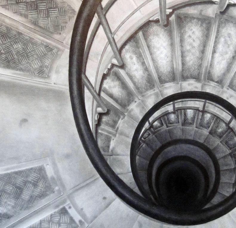
Model building has been the most rewarding piece in architecture school. Using my hands to construct a 3-dimensional representation of the ideas racing through me, is the synthesis of my designs. A major focus of my design work is constructability and detailing. Modeling allows me to truely understand the building and all its parts.
MODEL BUILDINGentrance to highland park libary stair of the artists house
back facade of the rachofsky house

interior view of the rachofsky houseback facade of the lake house
interior view of wooden stair in the luthier’s studio

Photography is an outlet for capturing images that should not be forgotten. I am constantly surrounded by buildings, landscapes and art that influence me as a designer. In an effort to create a visual library to compile all my influences, I photograph the most important images. I learned while in Europe that it’s not the number of pictures you take, it’s how impactful they can be.
PHOTOGRAPHY