Embed Size (px)
Citation preview
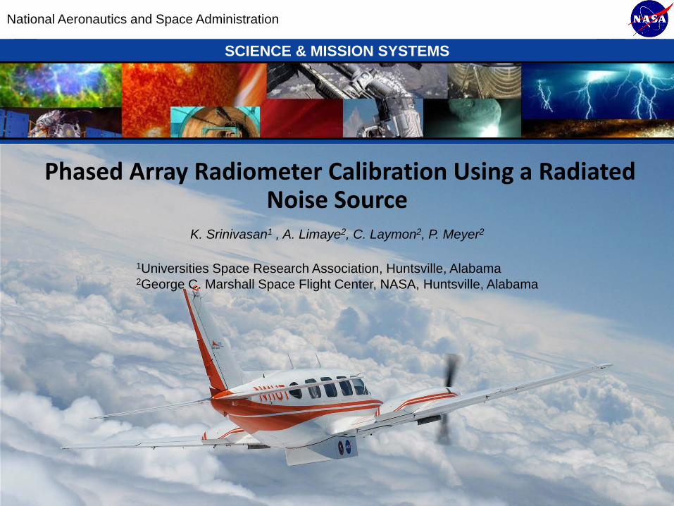
PHASED ARRAY RADIOMETER CALIBRATION USING A RADIATED NOISE SOURCE
Karthik Srinivasan V. (1), Ashutosh S. Limaye (1), Charles A. Laymon (2) and Paul J. Meyer(2)
(1)Universities Space Research Association, Huntsville, Alabama
(2)NASA Marshall Space Flight Center, Huntsville, Alabama
1. INTRODUCTION
Electronic beam steering capability of phased array antenna systems offer significant advantages when
used in real aperture imaging radiometers. The sensitivityof such systems is limited by the ability to
accurately calibrate variations in the antenna circuit characteristics. Passive antenna systems, which re-
quire mechanical rotation to scan the beam, have stable characteristics and the noise figure of the antenna
can be characterized with knowledge of its physical temperature [1],[2]. Phased array antenna systems
provide the ability to electronically steer the beam in any desired direction. Such antennas make use of
active components (amplifiers, phase shifters) to provide electronic scanning capability while maintaining
a low antenna noise figure. The gain fluctuations in the activecomponents can be significant, resulting
in substantial calibration difficulties [3]. In this paper,we introduce two novel calibration techniques that
provide an end-to-end calibration of a real-aperture, phased array radiometer system. Empirical data will
be shown to illustrate the performance of both methods.
2. ONE DIODE TECHNIQUE
Fig 1 shows a simplified block diagram of a two load radiometersystem [4] with a phased array antenna
array. Fig 2 shows the configuration of each active antenna element and the center element of the array. The
center element of the array radiates a Gaussian noise of known amplitude. A controller steps the radiometer
between target scene observations (with the radiated source turned off), internal load observations and an
observation of the target scene with the radiated noise source turned on. The difference between the
emission temperature measured with the noise source turnedon and off provides a method to compute the
gain of the antenna electronics. Though the plane of reference for the calibration is the front-end of the
radiometer, this technique can account for drifts in the gain of the antenna electronics, thus providing a
quasi- end-to-end calibration.
https://ntrs.nasa.gov/search.jsp?R=20100032967 2018-06-09T13:56:44+00:00Z
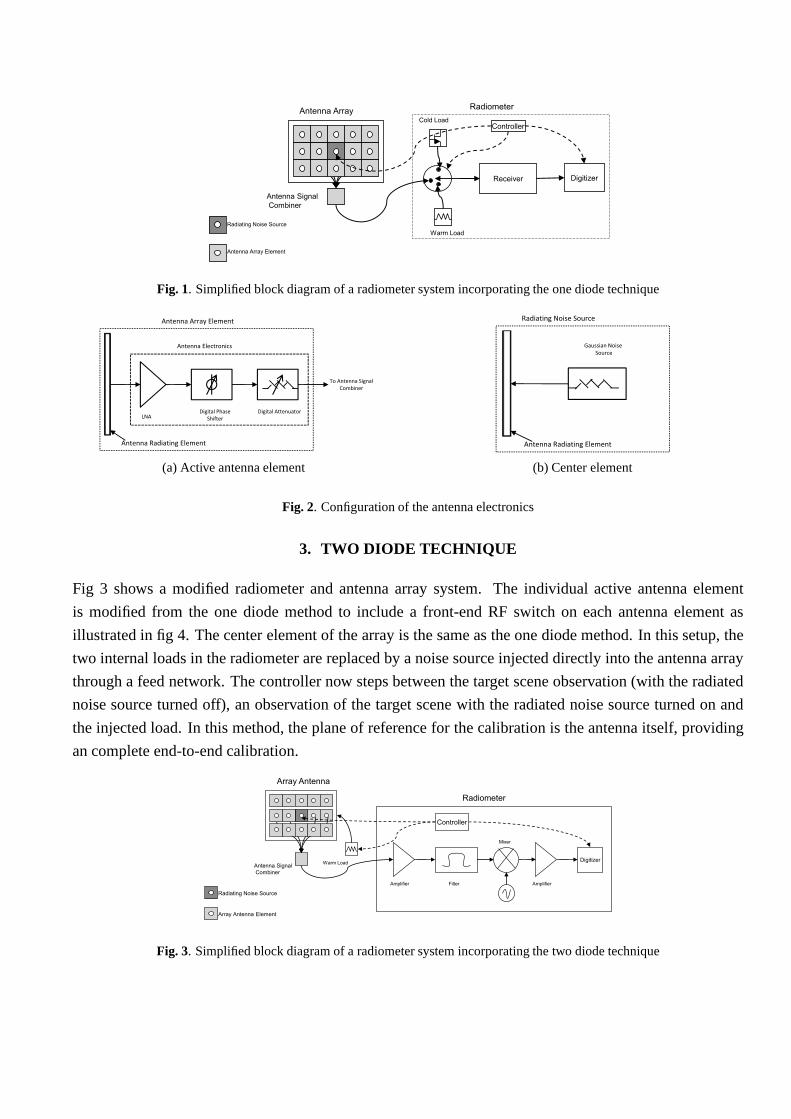
Fig. 1. Simplified block diagram of a radiometer system incorporating the one diode technique
Antenna Electronics
Antenna Array Element
Antenna Radiating Element
LNADigital Phase
Shifter
Digital Attenuator
To Antenna Signal
Combiner
(a) Active antenna element
Gaussian Noise
Source
Radiating Noise Source
Antenna Radiating Element
(b) Center element
Fig. 2. Configuration of the antenna electronics
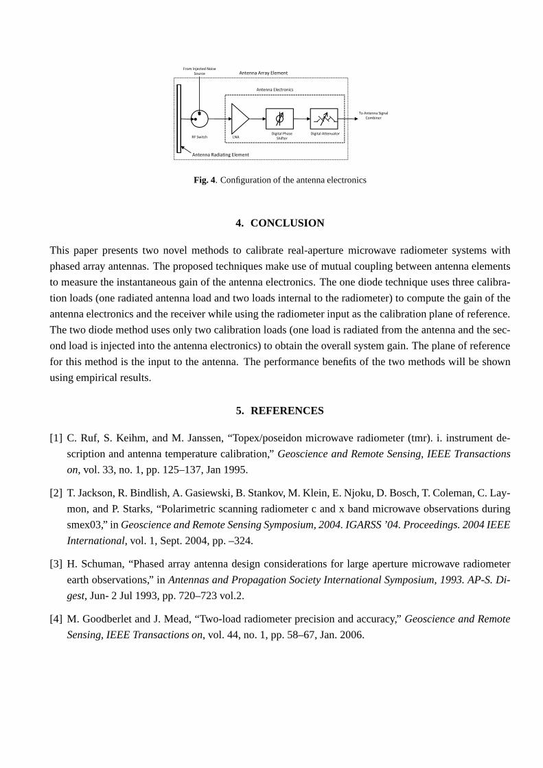
3. TWO DIODE TECHNIQUE
Fig 3 shows a modified radiometer and antenna array system. The individual active antenna element
is modified from the one diode method to include a front-end RFswitch on each antenna element as
illustrated in fig 4. The center element of the array is the same as the one diode method. In this setup, the
two internal loads in the radiometer are replaced by a noise source injected directly into the antenna array
through a feed network. The controller now steps between thetarget scene observation (with the radiated
noise source turned off), an observation of the target scenewith the radiated noise source turned on and
the injected load. In this method, the plane of reference forthe calibration is the antenna itself, providing
an complete end-to-end calibration.
Fig. 3. Simplified block diagram of a radiometer system incorporating the two diode technique
Antenna Electronics
Antenna Array Element
Antenna Radiating Element
LNADigital Phase
Shifter
Digital Attenuator
To Antenna Signal
Combiner
From Injected Noise
Source
RF Switch
Fig. 4. Configuration of the antenna electronics
4. CONCLUSION
This paper presents two novel methods to calibrate real-aperture microwave radiometer systems with
phased array antennas. The proposed techniques make use of mutual coupling between antenna elements
to measure the instantaneous gain of the antenna electronics. The one diode technique uses three calibra-
tion loads (one radiated antenna load and two loads internalto the radiometer) to compute the gain of the
antenna electronics and the receiver while using the radiometer input as the calibration plane of reference.
The two diode method uses only two calibration loads (one load is radiated from the antenna and the sec-
ond load is injected into the antenna electronics) to obtainthe overall system gain. The plane of reference
for this method is the input to the antenna. The performance benefits of the two methods will be shown
using empirical results.
5. REFERENCES
[1] C. Ruf, S. Keihm, and M. Janssen, “Topex/poseidon microwave radiometer (tmr). i. instrument de-
scription and antenna temperature calibration,”Geoscience and Remote Sensing, IEEE Transactions
on, vol. 33, no. 1, pp. 125–137, Jan 1995.
[2] T. Jackson, R. Bindlish, A. Gasiewski, B. Stankov, M. Klein, E. Njoku, D. Bosch, T. Coleman, C. Lay-
mon, and P. Starks, “Polarimetric scanning radiometer c andx band microwave observations during
smex03,” inGeoscience and Remote Sensing Symposium, 2004. IGARSS ’04. Proceedings. 2004 IEEE
International, vol. 1, Sept. 2004, pp. –324.
[3] H. Schuman, “Phased array antenna design considerations for large aperture microwave radiometer
earth observations,” inAntennas and Propagation Society International Symposium, 1993. AP-S. Di-
gest, Jun- 2 Jul 1993, pp. 720–723 vol.2.
[4] M. Goodberlet and J. Mead, “Two-load radiometer precision and accuracy,”Geoscience and Remote
Sensing, IEEE Transactions on, vol. 44, no. 1, pp. 58–67, Jan. 2006.
MSFC SCIENCE & MISSION SYSTEMS
IEEE Geoscience and Remote Sensing Symposium, July 26‐30, 2010, Honolulu, Hawaii 1
National Aeronautics and Space Administration
SCIENCE & MISSION SYSTEMS
Phased Array Radiometer Calibration Using a Radiated Noise Source
K. Srinivasan1 , A. Limaye2, C. Laymon2, P. Meyer2
1Universities Space Research Association, Huntsville, Alabama2George C. Marshall Space Flight Center, NASA, Huntsville, Alabama
MSFC SCIENCE & MISSION SYSTEMS
IEEE Geoscience and Remote Sensing Symposium, July 26‐30, 2010, Honolulu, Hawaii 2
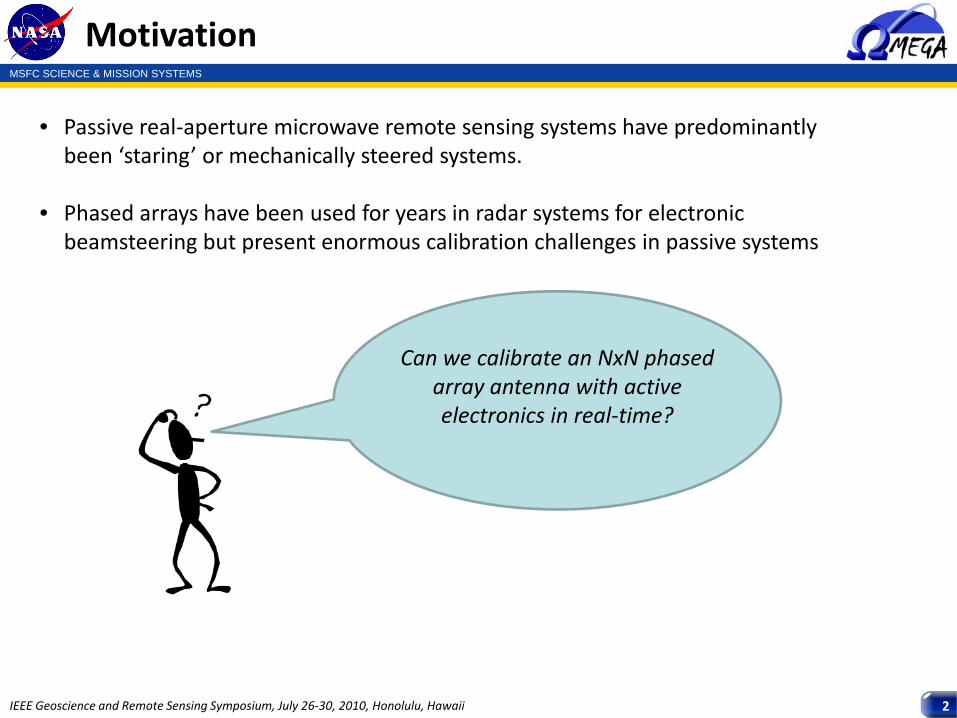
Motivation
• Passive real‐aperture microwave remote sensing systems have predominantly been ‘staring’ or mechanically steered systems.
• Phased arrays have been used for years in radar systems for electronic beamsteering but present enormous calibration challenges in passive systems
Can we calibrate an NxN phased array antenna with active electronics in real‐time?
MSFC SCIENCE & MISSION SYSTEMS
IEEE Geoscience and Remote Sensing Symposium, July 26‐30, 2010, Honolulu, Hawaii 3
Motivation
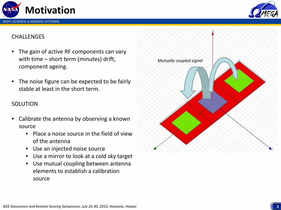
CHALLENGES
• The gain of active RF components can vary with time – short term (minutes) drift, component ageing.
• The noise figure can be expected to be fairly stable at least in the short term.
SOLUTION
• Calibrate the antenna by observing a known source
• Place a noise source in the field of view of the antenna
• Use an injected noise source• Use a mirror to look at a cold sky target• Use mutual coupling between antenna
elements to establish a calibration source
Mutually coupled signal
MSFC SCIENCE & MISSION SYSTEMS
IEEE Geoscience and Remote Sensing Symposium, July 26‐30, 2010, Honolulu, Hawaii 4
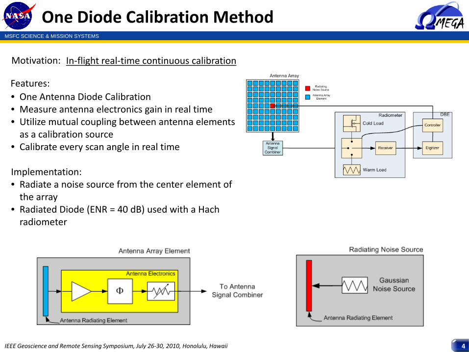
One Diode Calibration Method
Motivation: In‐flight real‐time continuous calibration
• One Antenna Diode Calibration• Measure antenna electronics gain in real time• Utilize mutual coupling between antenna elements as a calibration source
• Calibrate every scan angle in real time
Implementation:• Radiate a noise source from the center element of the array
• Radiated Diode (ENR = 40 dB) used with a Hachradiometer
Features:
MSFC SCIENCE & MISSION SYSTEMS
IEEE Geoscience and Remote Sensing Symposium, July 26‐30, 2010, Honolulu, Hawaii 5
One Diode Method
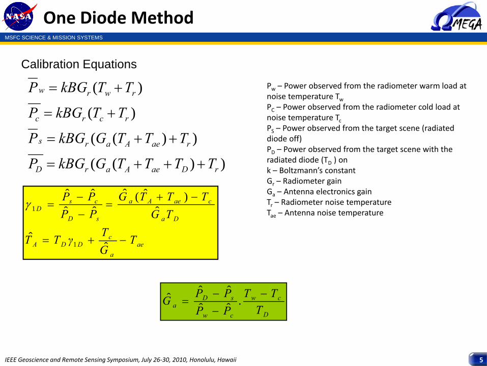
Calibration Equations
))((
))((
)(
)(
rDaeAarD
raeAars
rcrc
rwrw
TTTTGkBGP
TTTGkBGP
TTkBGP
TTkBGP
+++=
++=
+=
+=
aea
cDDA
Da
caeAa
sD
csD
TGTγTT
TGTTTG
PPPP
−+=
−+=
−−
=
ˆˆ
ˆ)ˆ(ˆ
ˆˆˆˆ
1
1γ
Pw – Power observed from the radiometer warm load at noise temperature TwPC – Power observed from the radiometer cold load at noise temperature TcPS – Power observed from the target scene (radiated diode off)PD – Power observed from the target scene with the radiated diode (TD ) onk – Boltzmann’s constantGr – Radiometer gainGa – Antenna electronics gainTr – Radiometer noise temperatureTae – Antenna noise temperature
D
cw
cw
sDa T
TTPPPPG −
−−
= .ˆˆˆˆˆ
MSFC SCIENCE & MISSION SYSTEMS
IEEE Geoscience and Remote Sensing Symposium, July 26‐30, 2010, Honolulu, Hawaii 6
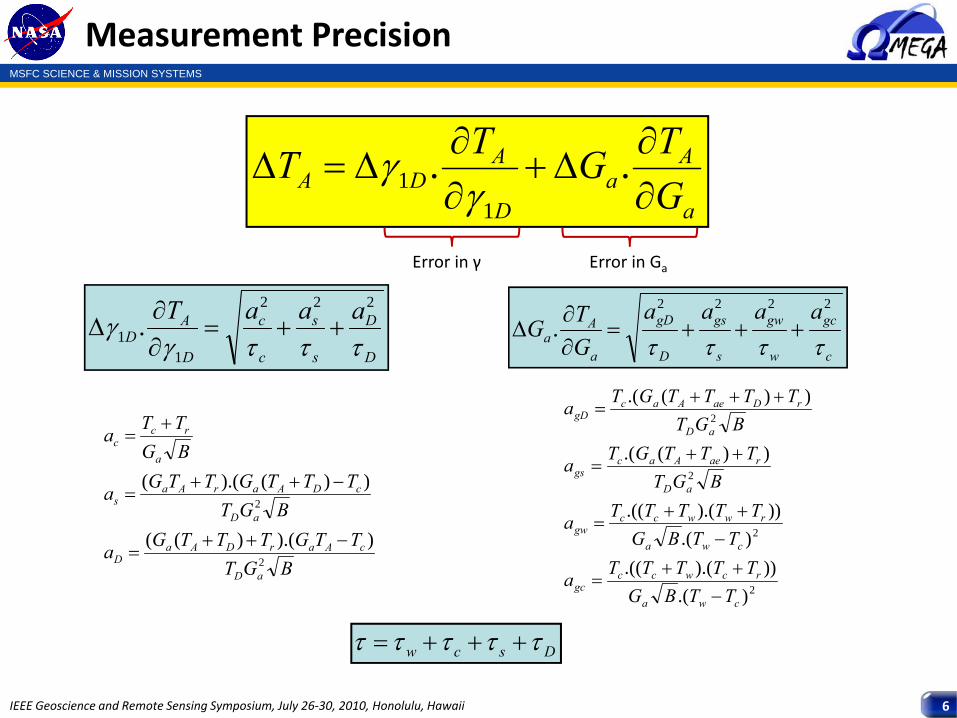
Measurement Precision
a
Aa
D
ADA G
TGTT∂∂
Δ+∂∂
Δ=Δ ..1
1 γγ
Dscw τττττ +++=
D
D
s
s
c
c
D
AD
aaaTτττγ
γ222
11 . ++=
∂∂
Δc
gc
w
gw
s
gs
D
gD
a
Aa
aaaaGTG
ττττ
2222
. +++=∂∂
Δ
2
2
2
2
).())).(.((
).())).(.((
))(.(
))(.(
cwa
rcwccgc
cwa
rwwccgw
aD
raeAacgs
aD
rDaeAacgD
TTBGTTTTTa
TTBGTTTTTa
BGTTTTGTa
BGTTTTTGTa
−++
=
−++
=
++=
+++=
BGTTTGTTTGa
BGTTTTGTTGa
BGTTa
aD
cAarDAaD
aD
cDAarAas
a
rcc
2
2
)).()((
))().((
−++=
−++=
+=
Error in γ Error in Ga
MSFC SCIENCE & MISSION SYSTEMS
IEEE Geoscience and Remote Sensing Symposium, July 26‐30, 2010, Honolulu, Hawaii 7
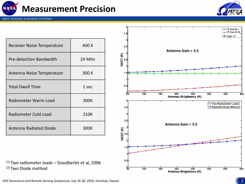
Measurement Precision
Antenna Gain = 3.5
(1) Two radiometer loads – Goodberlet et al, 2006(2) Two Diode method
Receiver Noise Temperature 400 K
Pre‐detection Bandwidth 24 MHz
Antenna Noise Temperature 300 K
Total Dwell Time 1 sec
Radiometer Warm Load 300K
Radiometer Cold Load 210K
Antenna Radiated Diode 300K
Antenna Gain = 3.5
MSFC SCIENCE & MISSION SYSTEMS
IEEE Geoscience and Remote Sensing Symposium, July 26‐30, 2010, Honolulu, Hawaii 8
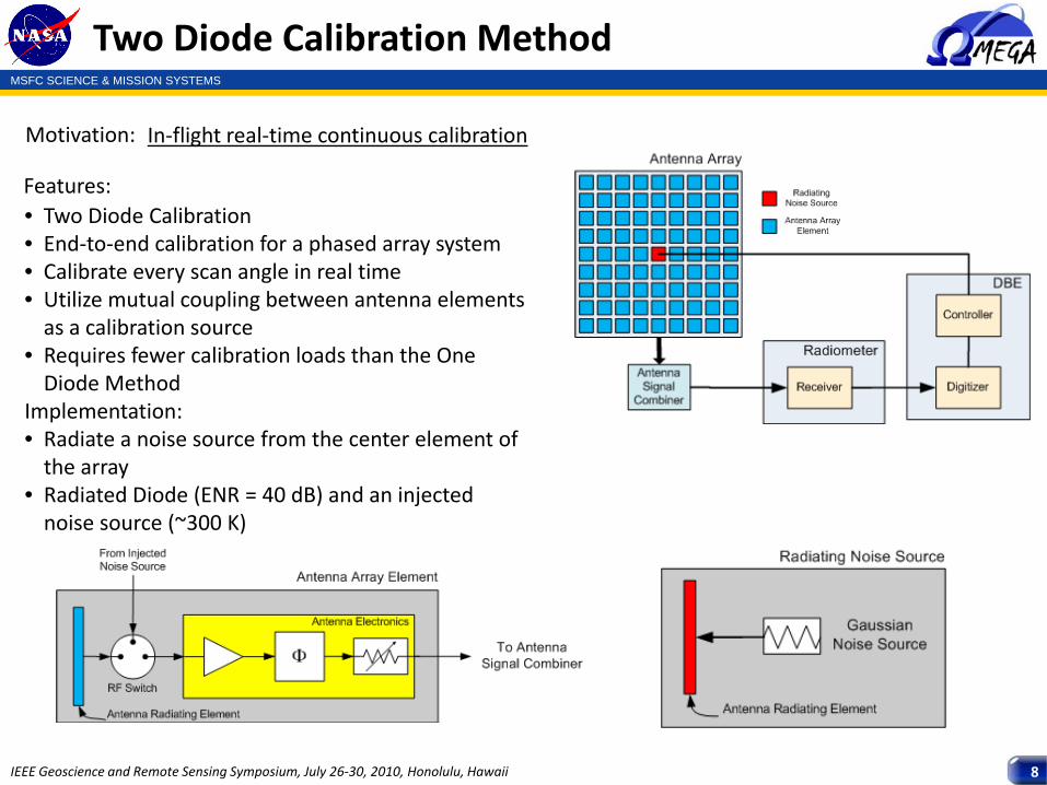
Two Diode Calibration Method
Motivation: In‐flight real‐time continuous calibration
• Two Diode Calibration• End‐to‐end calibration for a phased array system• Calibrate every scan angle in real time• Utilize mutual coupling between antenna elements as a calibration source
• Requires fewer calibration loads than the One Diode Method
Implementation:• Radiate a noise source from the center element of the array
• Radiated Diode (ENR = 40 dB) and an injected noise source (~300 K)
Features:
MSFC SCIENCE & MISSION SYSTEMS
IEEE Geoscience and Remote Sensing Symposium, July 26‐30, 2010, Honolulu, Hawaii 9
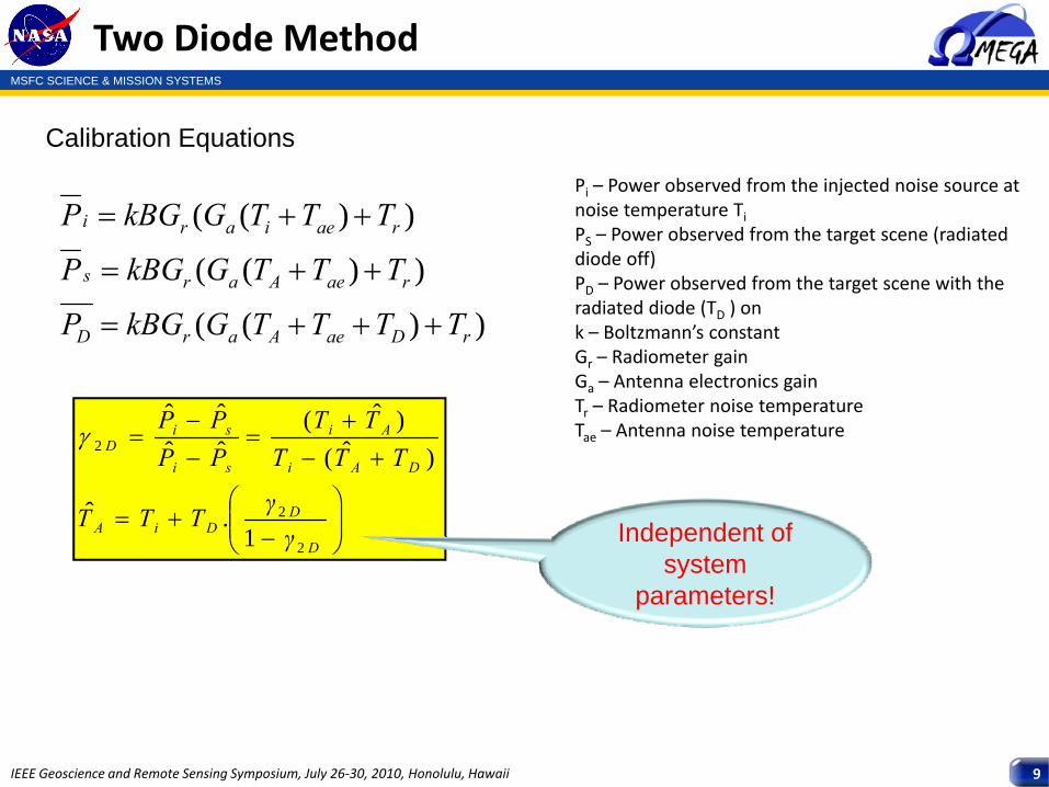
Two Diode Method
Calibration Equations
))((
))((
))((
rDaeAarD
raeAars
raeiari
TTTTGkBGP
TTTGkBGP
TTTGkBGP
+++=
++=
++=
⎟⎟⎠
⎞⎜⎜⎝
⎛−
+=
+−+
=−−
=
D
DDiA
DAi
Ai
si
siD
γγTTT
TTTTT
PPPP
2
2
2
1.ˆ
)ˆ()ˆ(
ˆˆˆˆ
γ
Pi – Power observed from the injected noise source at noise temperature TiPS – Power observed from the target scene (radiated diode off)PD – Power observed from the target scene with the radiated diode (TD ) onk – Boltzmann’s constantGr – Radiometer gainGa – Antenna electronics gainTr – Radiometer noise temperatureTae – Antenna noise temperature
Independent of system
parameters!
MSFC SCIENCE & MISSION SYSTEMS
IEEE Geoscience and Remote Sensing Symposium, July 26‐30, 2010, Honolulu, Hawaii 10
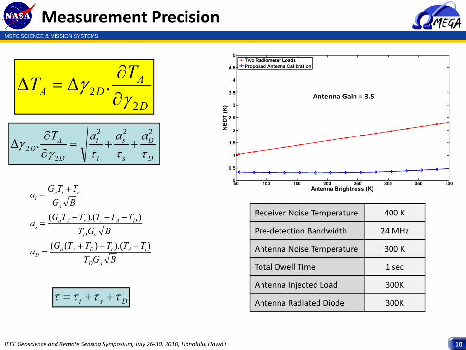
Measurement Precision
D
ADA
TT2
2 .γ
γ∂∂
Δ=Δ
Dsi ττττ ++=
D
D
s
s
i
i
D
AD
aaaTτττγ
γ222
22 . ++=
∂∂
Δ
BGTTTTTTGa
BGTTTTTTGa
BGTTGa
aD
iArDAaD
aD
DAirAas
a
riai
)).()((
)).((
−++=
−−+=
+=
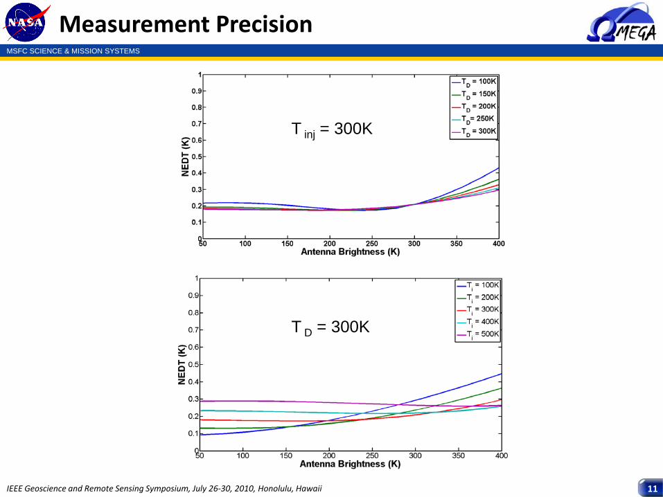
Receiver Noise Temperature 400 K
Pre‐detection Bandwidth 24 MHz
Antenna Noise Temperature 300 K
Total Dwell Time 1 sec
Antenna Injected Load 300K
Antenna Radiated Diode 300K
Antenna Gain = 3.5
MSFC SCIENCE & MISSION SYSTEMS
IEEE Geoscience and Remote Sensing Symposium, July 26‐30, 2010, Honolulu, Hawaii 11
Measurement Precision
T inj = 300K
T D = 300K
MSFC SCIENCE & MISSION SYSTEMS
IEEE Geoscience and Remote Sensing Symposium, July 26‐30, 2010, Honolulu, Hawaii 12
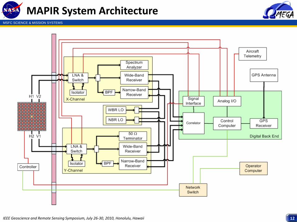
MAPIR System Architecture
MSFC SCIENCE & MISSION SYSTEMS
IEEE Geoscience and Remote Sensing Symposium, July 26‐30, 2010, Honolulu, Hawaii 13
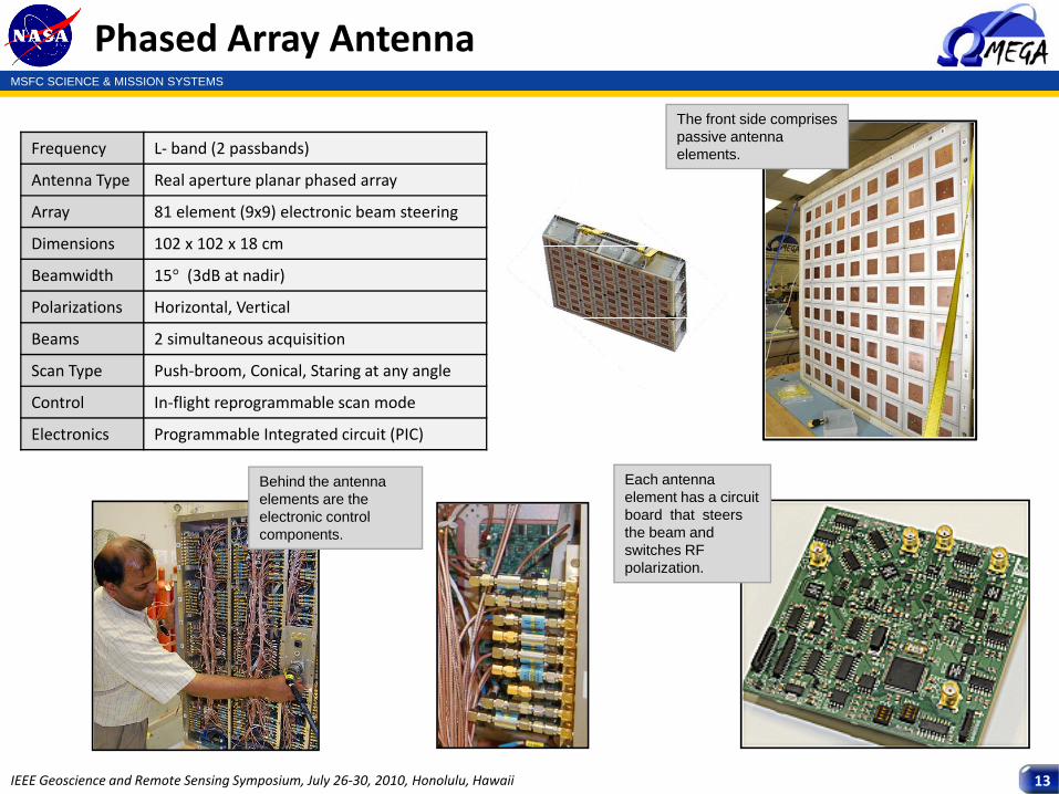
Phased Array Antenna
The front side comprises passive antenna elements.
Behind the antenna elements are the electronic control components.
Each antenna element has a circuit board that steers the beam and switches RF polarization.
Frequency L‐ band (2 passbands)
Antenna Type Real aperture planar phased array
Array 81 element (9x9) electronic beam steering
Dimensions 102 x 102 x 18 cm
Beamwidth 15° (3dB at nadir)
Polarizations Horizontal, Vertical
Beams 2 simultaneous acquisition
Scan Type Push‐broom, Conical, Staring at any angle
Control In‐flight reprogrammable scan mode
Electronics Programmable Integrated circuit (PIC)
MSFC SCIENCE & MISSION SYSTEMS
IEEE Geoscience and Remote Sensing Symposium, July 26‐30, 2010, Honolulu, Hawaii 14
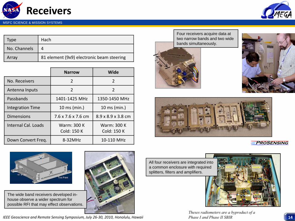
Receivers
Four receivers acquire data at two narrow bands and two wide bands simultaneously.
The wide band receivers developed in-house observe a wider spectrum for possible RFI that may effect observations.
All four receivers are integrated into a common enclosure with required splitters, filters and amplifiers.
shown
Theses radiometers are a byproduct of a Phase I and Phase II SBIR
Type Hach
No. Channels 4
Array 81 element (9x9) electronic beam steering
Narrow Wide
No. Receivers 2 2
Antenna Inputs 2 2
Passbands 1401‐1425 MHz 1350‐1450 MHz
Integration Time 10 ms (min.) 10 ms (min.)
Dimensions 7.6 x 7.6 x 7.6 cm 8.9 x 8.9 x 3.8 cm
Internal Cal. Loads Warm: 300 KCold: 150 K
Warm: 300 KCold: 150 K
Down Convert Freq. 8‐32MHz 10‐110 MHz
MSFC SCIENCE & MISSION SYSTEMS
IEEE Geoscience and Remote Sensing Symposium, July 26‐30, 2010, Honolulu, Hawaii 15
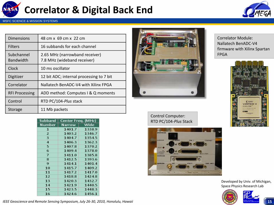
Correlator & Digital Back End
Developed by Univ. of Michigan, Space Physics Research Lab
Correlator Module: Nallatech BenADC‐V4 firmware with Xilinx Spartan FPGA
Control Computer: RTD PC/104‐Plus Stack
Dimensions 48 cm x 69 cm x 22 cm
Filters 16 subbands for each channel
SubchannelBandwidth
2.65 MHz (narrowband receiver)7.8 MHz (wideband receiver)
Clock 10 ms oscillator
Digitizer 12 bit ADC; internal processing to 7 bit
Correlator Nallatech BenADC‐V4 with Xilinx FPGA
RFI Processing ADD method: Computes I & Q moments
Control RTD PC/104‐Plus stack
Storage 11 Mb packets
MSFC SCIENCE & MISSION SYSTEMS
IEEE Geoscience and Remote Sensing Symposium, July 26‐30, 2010, Honolulu, Hawaii 16
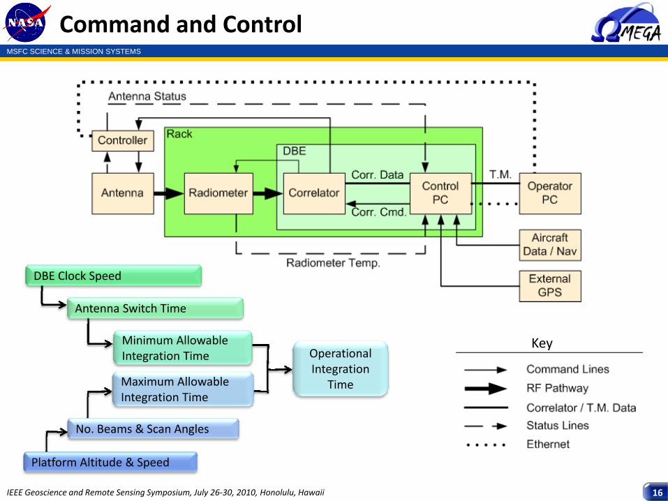
Command and Control
Key
Platform Altitude & Speed
No. Beams & Scan Angles
Maximum Allowable Integration Time
DBE Clock Speed
Minimum Allowable Integration Time Operational
Integration Time
Antenna Switch Time
MSFC SCIENCE & MISSION SYSTEMS
IEEE Geoscience and Remote Sensing Symposium, July 26‐30, 2010, Honolulu, Hawaii 17
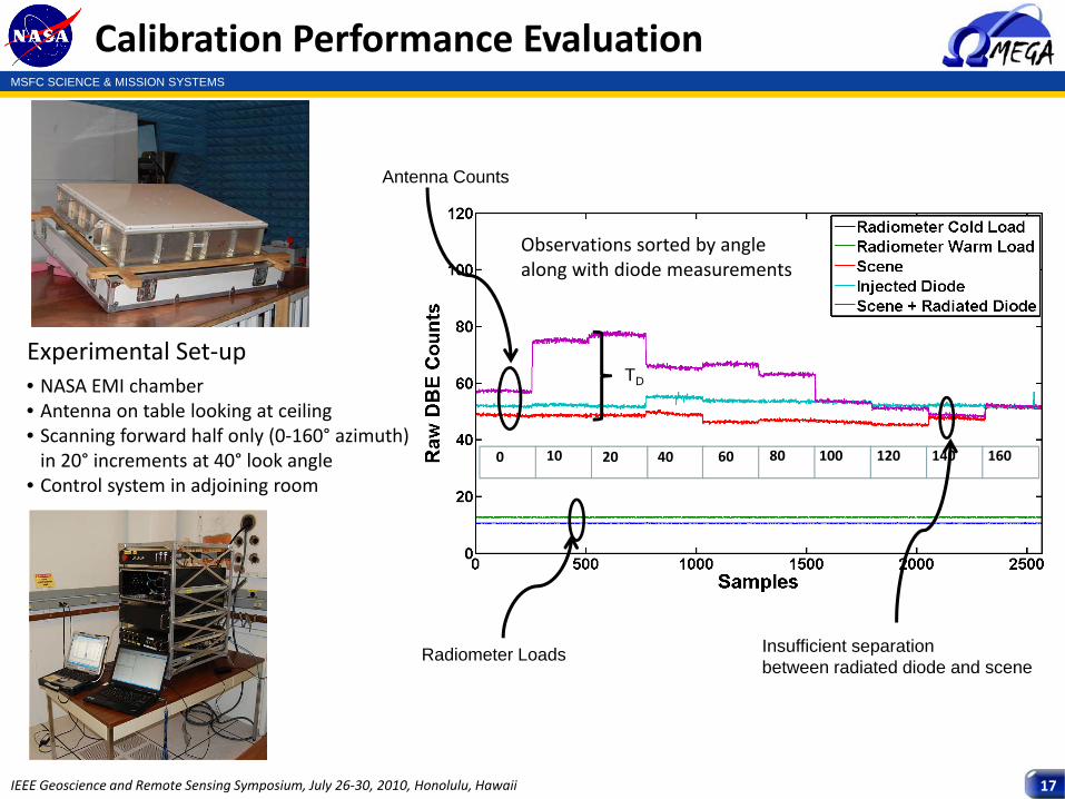
Calibration Performance Evaluation
Observations sorted by angle along with diode measurements
Experimental Set‐up• NASA EMI chamber• Antenna on table looking at ceiling• Scanning forward half only (0‐160° azimuth) in 20° increments at 40° look angle
• Control system in adjoining room
10080 16014012010 20 40 600
Radiometer Loads
Antenna Counts
Insufficient separation between radiated diode and scene
TD
MSFC SCIENCE & MISSION SYSTEMS
IEEE Geoscience and Remote Sensing Symposium, July 26‐30, 2010, Honolulu, Hawaii 18
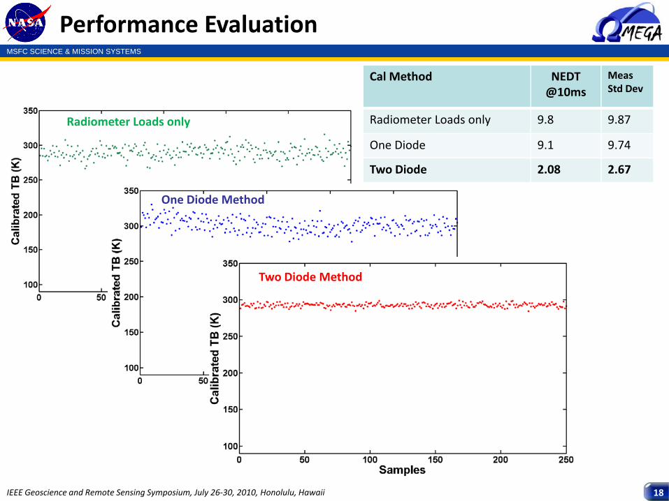
Performance Evaluation
Radiometer Loads only
One Diode Method
Two Diode Method
Cal Method NEDT @10ms
MeasStd Dev
Radiometer Loads only 9.8 9.87
One Diode 9.1 9.74
Two Diode 2.08 2.67
MSFC SCIENCE & MISSION SYSTEMS
IEEE Geoscience and Remote Sensing Symposium, July 26‐30, 2010, Honolulu, Hawaii 19
Challenges
• The amplitude of the mutually coupled signal is a function of scan angle – results in different radiated diode observations at each scan angle
• Impact of the difference in system noise temperature due to front‐end antenna switch loss as a function of switch position
• Efficiency of the radiated diode as a function of antenna size? Can this be overcome by using multiple radiating elements embedded within the array?
MSFC SCIENCE & MISSION SYSTEMS
IEEE Geoscience and Remote Sensing Symposium, July 26‐30, 2010, Honolulu, Hawaii 20
Conclusions & Future Work
Conclusions
Future Work
• Use of a radiated noise diode as a calibration source for an antenna array can be (relatively) simple to implement and significant applications
• First results are promising and indicate good potential for beam forming radiometers
• Opportunities for improvement
• Address scan angle dependent mutual coupling issues• Analyze efficiency of calibration as a function of antenna size• Improve the injected feed network
MSFC SCIENCE & MISSION SYSTEMS
IEEE Geoscience and Remote Sensing Symposium, July 26‐30, 2010, Honolulu, Hawaii 21
Questions