Embed Size (px)
Citation preview

Ventilation modes in intensive care
Karin Deden

Important note
This brochure does not replace the instructions for use. Prior to using a ventilator the corresponding instructions for use must always be read and understood.

Ventilation modes in intensive care
Karin Deden

04|
Manufacturer:Drägerwerk AG & Co. KGaAMoislinger Allee 53–5523558 Lübeck, Germany
www.draeger.com
VENTILATION MODES IN INTENSIVE CARE | CONTENTS

04|
CONTENTS
Important note 02Preface 06Introduction 09Mechanical ventilation 11Volume-controlled ventilation 18AutoFlow 20VC-CMV 22VC-AC 24VC-SIMV 26VC-MMV 28Pressure-controlled ventilation 30Volume guarantee 32PC-CMV 34PC-AC 36PC-SIMV 38PC-BIPAP 40PC-APRV 42PC-PSV 44Spontaneous/assisted ventilation 46SPN-CPAP/PS 48Variable PS 50SPN-CPAP/VS 52SPN-PPS 54Specific neonatal ventilation modes 56SPN-CPAP 58PC-HFO 60PC-MMV 62Extended ventilation settings 64Nomenclature comparison 66Glossary 68References 70
05

06|VENTILATION MODES IN INTENSIVE CARE | PREFACE
TOWARDS A CLASSIFICATION FOR VENTILATIONIn 1977, Steven McPherson wrote the first popular book on ventilation equipment in the USA. Ventilation was discussed on 65 percent of the pages, but only 3 ventilation modes were explained in detail: “controlled”, “assisted” and “spontaneous breathing”. Some modes were not mentioned in the specification tables for ventilators in the book. Instead, the book focused on specific drive mechanisms and configurations as well as on how configurations could be combined into identifiable operating modes. The description of a ventilator in the book was, for example, akin to an “… electrically driven rotating piston, double circuit, timed, time and volume limited controller …”. It must be taken into account that the concept of “IMV” (Intermittent Mandatory Ventilation) had only been invented four years earlier.
The seventh edition of McPherson’s ventilator book was published in 2004. Interestingly, about two thirds of the book are still dedicated to the topic of ventilation. In this edition, only 22 ventilation modes are described on 19 pages. However, on the subsequent pages where specific ventilators are described, 93 different ventilation modes are mentioned. These are, however, not 93 different modes. In many instances, different names are used for identical modes (e.g. the pressure control ventilation plus adaptive pressure ventilation in the Hamilton Galileo corresponds to the pressure regulated volume control in the Maquet Servo 300), and in some cases, the same name is used for different modes (assist/control in the Puritan Bennett 840 is a kind of volume-controlled ventilation, whilst assist/control in the Bear Cub ventilator for infants is a kind of pressure-controlled ventilation).
As in many other fields, the technical complexity has increased significantly in ventilation. Today modern ventilators might feature more than two dozen modes; some even utilize computer-assisted artificial intelligence. Within a single human generation, ventilators have spanned approximately 5 generations
Preface

06|07
in development. What has not been developed is a standardized system sufficiently describing this technical complexity. This causes four main problems: (1) published studies about ventilation are difficult to compare making it hard to compile and describe factual statements; (2) there is little consistency between medical training programs with regard to the nomen-clature and descriptions of how ventilators work; (3) clinical staff working in clinics where ventilators of different manufacturers are used (which is quite common) do not have the time or training resources for adequate training and practice in using all modes in all ventilators, making optimum patient care difficult and (4) manufacturers cannot discuss the precise operation of their products easily with future customers, limiting the effectiveness of sales and training and in turn reinforcing the other problems. To date, neither manufacturers nor professional associations have found a common consensus about a classification for ventilation. However, certain efforts have already been made: The committee TC 121 (Anesthetic and Respiratory Equipment) of the International Organization for Standardization has a subcommittee (SC3 Lung Ventilators and Related Equipment) working on a standardized terminology. „Integrating the Healthcare Enterprise“ (IHE) is an initiative of experts and health care companies to improve the exchange of information between computer systems in the health care sector. The IHE domain „Patient Care Device“ works on the basis of an RTM profile (Rosetta Terminology Mapping) connecting provider-specific terminology with standardized terminology (based on ISO/IEEE 11073-10101), predomi-nantly for emergency care equipment such as ventilators. Its aim is the uniform representation of key equipment data, especially if these are communicated to a gateway for health care applications. The increasing use of electronic patient files in hospitals worldwide makes the efforts of these organizations indispensable. Finding a consensus between so many different interested parties is a long and difficult process. With the compilation of a common nomenclature for all patient groups in intensive care, anesthesia and during monitoring, Dräger makes an important contribution to these efforts. Dräger recognizes the necessity of practical clarity when
08|VENTILATION MODES IN INTENSIVE CARE | PREFACE
describing modes. As in other companies, the advanced product designs of Dräger: has its advantages and disadvantages They provide the latest life- saving technology, but they are also confusingly complex, hampering the expansion of this technology. The purpose of this booklet is to describe the available modes for the Dräger ventilators in a systematic and informative manner. Although this might not serve as a universal classification for the modes, we hope that it will improve the understanding of the many available ventilation modes for Dräger devices and therefore ultimately improve patient care.
Robert L. Chatburn, BS, RRT-NPS, FAARCClinical Research ManagerRespiratory InstituteCleveland ClinicAdjunct Associate Professor Department of MedicineLerner College of Medicine of Case Western Reserve UniversityCleveland, Ohio, USA
08|09
If you follow a patient from an initial event such as an accident location all the way until he/she is released from hospital, you will notice that mechanical ventilation is necessary and used in many areas of patient care. Already at the accident location and during transportation, ventilation is provided using an emergency ventilator. During the operation in the hospital an anesthesia machine provides ventilation. Intensive care ventilators are available during the critical stay in intensive care. Even during the subsequent treatment on intermediate care wards, some patients require mechanical breathing support. Mechanical ventilation is required in all areas of the hospital. For neonatal patients, the mechanical ventilation starts soon after birth using a ventilator or manual ventilation bag, usually in the labor room or operating room. After a brief transport to the neonatal intensive care ward, these small patients are ventilated mechanically until their condition is stable. In the various departments with their corresponding patient groups, different ventilation modes were developed on the basis of the individual needs and requirements. Different names for principally identical modes cause confusion and place heavy demands on the user. Within international literature, too, different names are used for the same ventilation mode. For example, the literature often mentions CMV/AC whereas for the ventilation of adults with Dräger equipment the term IPPV/IPPVassist is used. Dräger recognizes how difficult the current situation is for the user and therefore developed a uniform nomenclature for ventilation modes from emergency provision through anesthesia and intensive care to monitoring/IT.
This brochure intends to facilitate the move from the old to the new nomen-clature. For this reason, the properties and control principles of the individual ventilation modes are briefly outlined. The focus of the mode descriptions is the intensive care ventilation for adults, pediatric patients and neonatal patients. For a precise comparison of the designations, the brochure concludes with a comparison of the ventilation modes in the previous and the new
Introduction

10|VENTILATION MODES IN INTENSIVE CARE | INTRODUCTION
nomenclature. The comparison of the designations is given for the intensive care ventilation of adults and neonatal patients as well as for anesthesia.
10|11
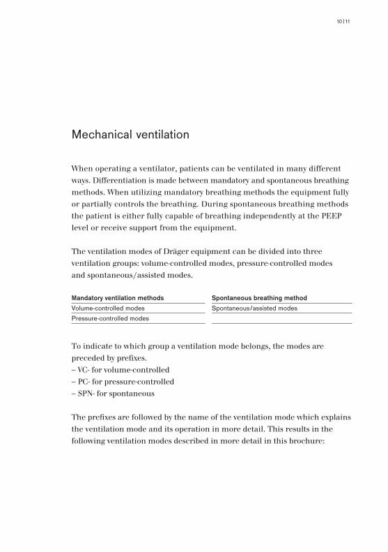
When operating a ventilator, patients can be ventilated in many different ways. Differentiation is made between mandatory and spontaneous breathing methods. When utilizing mandatory breathing methods the equipment fully or partially controls the breathing. During spontaneous breathing methods the patient is either fully capable of breathing independently at the PEEP level or receive support from the equipment.
The ventilation modes of Dräger equipment can be divided into three ventilation groups: volume-controlled modes, pressure-controlled modes and spontaneous/assisted modes.
To indicate to which group a ventilation mode belongs, the modes are preceded by prefixes. – VC- for volume-controlled– PC- for pressure-controlled– SPN- for spontaneous
The prefixes are followed by the name of the ventilation mode which explains the ventilation mode and its operation in more detail. This results in the following ventilation modes described in more detail in this brochure:
Mechanical ventilation
Mandatory ventilation methods Spontaneous breathing methodVolume-controlled modes Spontaneous/assisted modesPressure-controlled modes

12|VENTILATION MODES IN INTENSIVE CARE | MECHANICAL VENTILATION
For some ventilation modes, there are extended configurations, such as AutoFlow® (AF), Volume Guarantee (VG) or PS (Pressure Support). These extended configurations are explained in more detail in this brochure.
In order to understand the particularities of the modes, it is important to know the control and actuating variables.
FORMS OF MANDATORY BREATHThe control variable, primary affected or controlled by the equipment, is identified by the prefix VC or PC. The control variables are discussed in more detail in the sections on volume- and pressure-controlled ventilation.
When controlling the mandatory ventilation, a difference is made between the control of the start of inspiration and the control of the start of expiration.
CONTROL VARIABLE - START OF INSPIRATIONThe inspiration can be initiated by the patient or by the equipment. This is called patient-triggered or mechanically triggered mandatory breath.
Volume-controlled Pressure-controlled Spontaneous/assistedVC-CMV PC-CMV SPN-CPAP/PSVC-AC PC-AC SPN-CPAP/VSVC-SIMV PC-SIMV SPN-PPSVC-MMV PC-BIPAP SPN-CPAP PC-APRV PC-PSV PC-HFO PC-MMV
Paw
Flow
Trigger threshold
PEEP
t
t
12|13
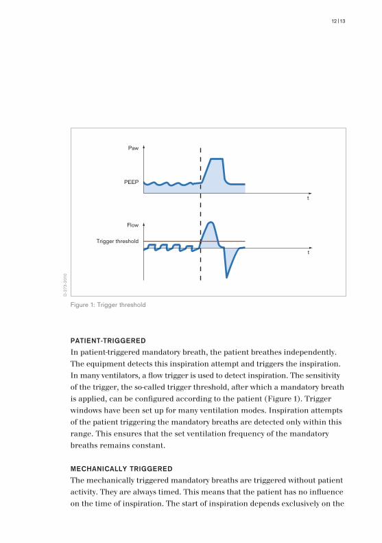
PATIENT-TRIGGEREDIn patient-triggered mandatory breath, the patient breathes independently. The equipment detects this inspiration attempt and triggers the inspiration. In many ventilators, a flow trigger is used to detect inspiration. The sensitivity of the trigger, the so-called trigger threshold, after which a mandatory breath is applied, can be configured according to the patient (Figure 1). Trigger windows have been set up for many ventilation modes. Inspiration attempts of the patient triggering the mandatory breaths are detected only within this range. This ensures that the set ventilation frequency of the mandatory breaths remains constant.
MECHANICALLY TRIGGEREDThe mechanically triggered mandatory breaths are triggered without patient activity. They are always timed. This means that the patient has no influence on the time of inspiration. The start of inspiration depends exclusively on the
D-2
73-2
010
Figure 1: Trigger threshold
14|VENTILATION MODES IN INTENSIVE CARE | MECHANICAL VENTILATION
Paw
Flow
Start of inspiration End of inspiration
100 %
x %
t
t
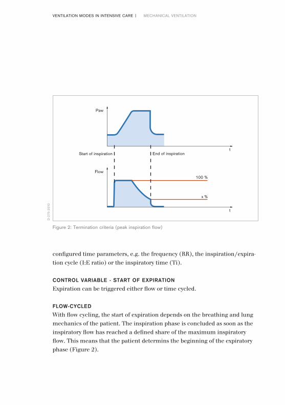
configured time parameters, e.g. the frequency (RR), the inspiration/expira-tion cycle (I:E ratio) or the inspiratory time (Ti).
CONTROL VARIABLE - START OF EXPIRATIONExpiration can be triggered either flow or time cycled.
FLOW-CYCLEDWith flow cycling, the start of expiration depends on the breathing and lung mechanics of the patient. The inspiration phase is concluded as soon as the inspiratory flow has reached a defined share of the maximum inspiratory flow. This means that the patient determins the beginning of the expiratory phase (Figure 2).
D-2
75-2
010
Figure 2: Termination criteria (peak inspiration flow)

14|15
TIME-CYCLEDIf the start of expiration is time-cycled, then only the inspiratory time (Ti) determines the starting point of expiration. The patient has no, or in some modes only a minor, influence on the duration of the inspiration phase.
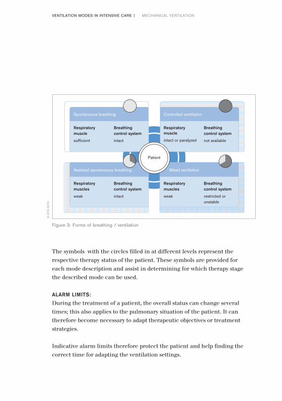
WHICH VENTILATION MODE FOR WHICH TREATMENT PHASE?During the ventilation treatment, a patient goes through different phases marked by different support requirements (Figure 3).
At the start, the patient might be fully sedated. His breathing control is not operating and he depends on controlled ventilation.
If the sedation is subsequently reduced, breathing control may be active to a certain extent, albeit unstable. However, the breathing muscles may be too weak to cope with the breathing task independently. A mixed ventilation is required that permits spontaneous breathing but shares the breathing load between the patient and the equipment.
Once the patient has achieved independent and stable breathing, but remains weak, he requires gentle support in breathing. The patient’s breathing can be supported using spontaneous/assisted ventilation.
If the patient has recovered sufficiently to regain his full breathing ability and his breathing muscles have regained their strength, he can breathe spontaneously by himself.
Control principles
Start of inspiration Start of expirationPatient-triggered Flow-cycledMachine triggered Time-cycled
16|VENTILATION MODES IN INTENSIVE CARE | MECHANICAL VENTILATION
Patient
Respiratory muscle
sufficient
Breathing control system
intact
Respiratory muscle
intact or paralyzed
Breathing control system
not available
Respiratory muscles
weak
Breathing control system
intact
Respiratory muscles
weak
Breathing control system
restricted or unstable
Spontaneous breathing Controlled ventilation
Assisted spontaneous breathing Mixed ventilation
The symbols with the circles filled in at different levels represent the respective therapy status of the patient. These symbols are provided for each mode description and assist in determining for which therapy stage the described mode can be used.
ALARM LIMITS:During the treatment of a patient, the overall status can change several times; this also applies to the pulmonary situation of the patient. It can therefore become necessary to adapt therapeutic objectives or treatment strategies.
Indicative alarm limits therefore protect the patient and help finding the correct time for adapting the ventilation settings.
D-2
74-2
010
Figure 3: Forms of breathing / ventilation

16|17
With every patient admission and every change in ventilation mode, the alarm limits should be checked and adjusted to the patient and the ventilation mode.
Changes in the lung properties and thus the Resistance (R) and Compliance (C) have different effects in the different ventilation modes.
For volume-controlled ventilation modes, the pressures are resulting variables. It is therefore important to adjust the alarm limit Phigh appropriately.
In the case of pressure-controlled ventilation modes, the applied tidal volume changes with a change of Resistance and Compliance. Here, particular attention must be paid to the alarm limits for VThigh, VTlow, MVhigh, MVlow
and RRhigh to ensure patient protection.
18|VENTILATION MODES IN INTENSIVE CARE | VOLUME-CONTROLLED VENTILATION
During volume-controlled ventilation, the set tidal volume is supplied by the ventilator at a constant flow. The inspiratory pressure is the resulting variable and changes dependent on the changing lung mechanics.The value controlled and kept at the target value by the equipment is the tidal volume (VT). The tidal volume and the number of mandatory breaths per minute (f) can be adjusted. This results in the minute volume (MV). The velocity at which the breathing volume (VT) is applied is adjusted by the flow, the constant inspiratory flow.
A breath can be divided into an inspiratory and expiratory phase. The duration of the inspiratory phase is defined by the inspiration time (Ti). If the inspira-tory flow is so high that the set breathing volume is reached before the set inspiratory time (Ti) has passed, there will be a pause in inspiration.
Because the pressures in the lung can vary in volume-controlled ventilation with a change in lung properties and thus the Resistance (R) and Compli-ance (C), it is important to set the alarm limit Phigh based on the patient. To ensure free breathing ability during the complete breathing cycle, and thus increase patient comfort, AutoFlow can be enabled during volume-controlled ventilation.
Volume-controlled ventilation modes are not available for the neonatal patient category.
Volume-controlled ventilation

18|19
FiO2 VT Ti RR PEEP Flow
21 1.70 520 12.0 5.0 21
Set the alarm limit Phigh patient-specific > Not available in the neonatal patient category
Volume-controlled modesVC-CMVVC-ACVC-SIMVVC-MMV
Due to the pressure limitation it is possiblethat the set VT is not always achievedMinute volume MV = VT * RRAutoFlow can be enabled for all volu-me-controlled modes
Pause
Insp.
PEEP
Paw
Flow
Pplat
Ti Te
1RR
Insp. Flow
D-2
55-2
010
D-5
-201
0
Figure 4: Possible ventilation settings for volume-controlled ventilation modes for adult patient category
Figure 5: Volume-controlled ventilation

20|VENTILATION MODES IN INTENSIVE CARE | CONTENTS
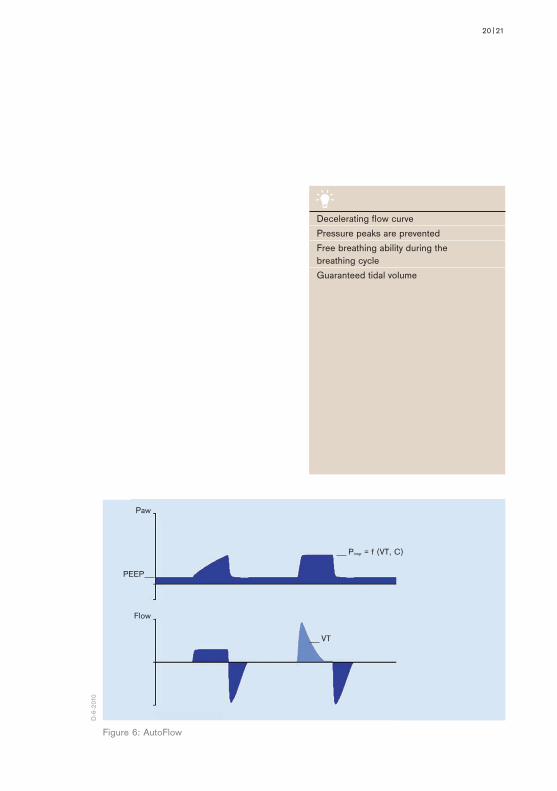
AUTOFLOW– extended ventilation configuration for all volume-controlled ventilation
modes (Figure 6)
AutoFlow ensures that the set tidal volume (VT) is applied with the necessary minimum pressure for all mandatory breaths.
If the Resistance (R) or Compliance (C) changes, the pressure adapts gradually in order to administer the set tidal volume (VT). This means that both the pressure and the flow are adjusted automatically.
During the whole breathing cycle, both during inspiration and expiration, the patient can breathe spontaneously.
20|21
PEEP
Paw
Flow
Pinsp = f (VT, C)
VT
Decelerating flow curvePressure peaks are preventedFree breathing ability during the breathing cycleGuaranteed tidal volume
D-6
-201
0
Figure 6: AutoFlow

22|VENTILATION MODES IN INTENSIVE CARE | VOLUME-CONTROLLED VENTILATION
VC-CMV(VOLUME CONTROL - CONTINUOUS MANDATORY VENTILATION)– volume-controlled – time cycled– machine-triggered– constant inspiratory flow (Figure 8)
In this volume-controlled ventilation mode, the patient receives the set tidal volume (VT) with every mandatory breath. The applied breathing volume is independent of changes in the lung mechanics.
The number of mandatory breath is defined by the frequency (RR). This means that the minute volume (MV) remains constant over time.

22|23
FiO2 VT Ti RR PEEP Flow
21 1.70 520 12.0 5.0 21
Pause
Insp.
PEEP
Paw
Flow
Pplat
Ti Te
1RR
Insp. Flow
Set the alarm limit Phigh patient-specific >
AutoFlow can be enabled
D-2
56-2
010
D-5
-201
0
Figure 7: Possible ventilation settings
Figure 8: VC-CMV
24|VENTILATION MODES IN INTENSIVE CARE | VOLUME-CONTROLLED VENTILATION
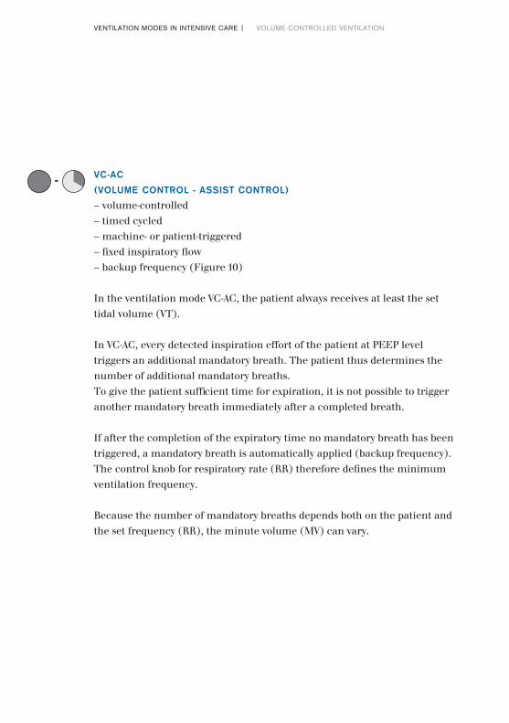
VC-AC(VOLUME CONTROL - ASSIST CONTROL)– volume-controlled– timed cycled– machine- or patient-triggered– fixed inspiratory flow – backup frequency (Figure 10)
In the ventilation mode VC-AC, the patient always receives at least the set tidal volume (VT).
In VC-AC, every detected inspiration effort of the patient at PEEP level triggers an additional mandatory breath. The patient thus determines the number of additional mandatory breaths. To give the patient sufficient time for expiration, it is not possible to trigger another mandatory breath immediately after a completed breath.
If after the completion of the expiratory time no mandatory breath has been triggered, a mandatory breath is automatically applied (backup frequency). The control knob for respiratory rate (RR) therefore defines the minimum ventilation frequency.
Because the number of mandatory breaths depends both on the patient and the set frequency (RR), the minute volume (MV) can vary.
--

24|25
FiO2 VT Ti RR PEEP Flow
21 1.70 520 12.0 5.0 21
Paw
Flow
Trigger window
Pause
Insp.
PEEP
Pplat
Ti Te
1RR
Insp. Flow
Set the alarm limit Phigh patient-specific >
AutoFlow can be enabledThe trigger sensitivity can be set
D-2
57-2
010
D-2
2552
-201
0
Figure 9: Possible ventilation settings
Figure 10: VC-AC
26|VENTILATION MODES IN INTENSIVE CARE | VOLUME-CONTROLLED VENTILATION
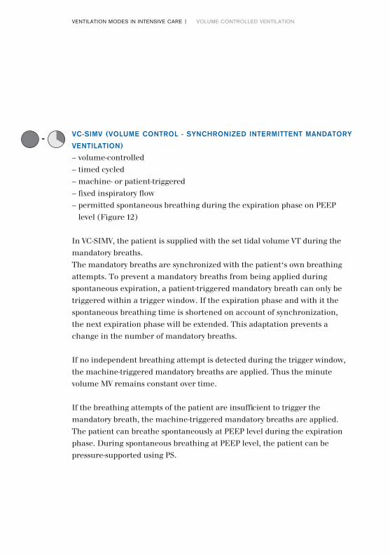
VC-SIMV (VOLUME CONTROL - SYNCHRONIZED INTERMITTENT MANDATORY VENTILATION)– volume-controlled– timed cycled– machine- or patient-triggered– fixed inspiratory flow – permitted spontaneous breathing during the expiration phase on PEEP
level (Figure 12)
In VC-SIMV, the patient is supplied with the set tidal volume VT during the mandatory breaths. The mandatory breaths are synchronized with the patient‘s own breathing attempts. To prevent a mandatory breaths from being applied during spontaneous expiration, a patient-triggered mandatory breath can only be triggered within a trigger window. If the expiration phase and with it the spontaneous breathing time is shortened on account of synchronization, the next expiration phase will be extended. This adaptation prevents a change in the number of mandatory breaths.
If no independent breathing attempt is detected during the trigger window, the machine-triggered mandatory breaths are applied. Thus the minute volume MV remains constant over time.
If the breathing attempts of the patient are insufficient to trigger the mandatory breath, the machine-triggered mandatory breaths are applied.The patient can breathe spontaneously at PEEP level during the expiration phase. During spontaneous breathing at PEEP level, the patient can be pressure-supported using PS.
--

26|27
Set the alarm limit Phigh patient-specific >
AutoFlow can be enabledThe trigger sensitivity can be set
FiO2 VT Ti RR PEEP ∆Psupp Slope Flow
21 1.70 500 12.0 5.0 14 0.2 20
Paw
Flow
Trigger window
PEEP
Ti 1RR
Insp. Flow
Pressure support PS
D-2
58-2
010
D-1
1-20
10
Figure 11: Possible ventilation settings
Figure 12: VC-SIMV

VENTILATION MODES IN INTENSIVE CARE | VOLUME-CONTROLLED VENTILATION 28|
VC-MMV(VOLUME CONTROL - MANDATORY MINUTE VOLUME)– volume-controlled– time cycled – machine- or patient-triggered– safeguarding the mandatory minute volume with permitted spontaneous
breathing on PEEP level (Figure 14)
VC-MMV guarantees that the patient always receives at least the set minute volume MV (MV=VT*RR).
The applied time-cycled, machine-triggered mandatory breaths are synchronized with the breathing effort of the patient.The patient can always breathe spontaneously at PEEP level. If the spontaneous breathing of the patient is insufficient to achieve the set (MV), machine-triggered time cycled mandatory breaths are applied. These mandatory breaths are synchronized with the patient’s own breathing attempts.
The set breathing frequency (RR) is therefore the maximum number of mandatory breaths.
During spontaneous breathing at PEEP level, the patient can be pressure-supported using PS.
--

28|29
FiO2 VT Ti RR PEEP ∆Psupp Slope Flow
21 1.60500 12.0 5.0 16 0.20 30
AutoFlow can be enabledThe trigger sensitivity can be set
Set the alarm limit Phigh patient-specific >Set the alarm limit RRhigh patient-specific >Set the alarm limit Vlow patient-specific <
Paw
Flow
Trigger window
PEEP
Ti
Insp. Flow
Pressure support PS
D-2
59-2
010
D-1
3-20
10
Figure 13: Possible ventilation settings
Figure 14: VC-MMV
30|VENTILATION MODES IN INTENSIVE CARE | PRESSURE-CONTROLLED VENTILATION
During pressure-controlled ventilation, two pressure levels are kept constant: the lower pressure level PEEP and the upper pressure level Pinsp. The volume and the decelerating flow are the resulting variables and can vary dependent on changes in the lung mechanics (Figure 16).
The value controlled and kept at target value by the equipment is the pressures Pinsp. The pressures PEEP, Pinsp and the number of mandatory breaths per minute (RR) can be adjusted. The difference between the two pressure levels PEEP and Pinsp, the breathing effort of the patient, and the lung mechanics determine the breathing volume (VT) supplied. The minute volume (MV) can vary. With the slope adjustment, the pressure increase can be set to the upper pressure level depending on the patient. During neonatal ventilation the flow adjustment is frequently used to determine this pressure increase. Both adjustments define the duration of the pressure increase from the lower to the higher pressure level.
A breath can be divided into an inspiratory and expiratory phase. The dura-tion of the inspiratory phase is defined by the inspiration time (Ti). During pressure-controlled ventilation, the upper pressure level Pinsp is maintained for the duration Ti. The time for the next mandatory breath results from the number of mandatory breaths per minute (RR) and the inspiratory time (Ti). This time control is not used in PC-PSV.
If the lung mechanics of the patient and with it the Resistance (R) and Compliance (C) vary during the ventilation treatment, this only influences the applied tidal volume. The pressures remain constant. The pressures are also maintained in case of leakage.
Pressure-controlled ventilation

30|31
Figure 15: Possible ventilation settings for pressure-controlled ventilation modes for adult patient category
Set alarm limit VThigh patient-specific >Set the alarm limit Vlow patient-specific <Set the alarm limit RRhigh patient-specific >Set alarm limit MVhigh patient-specific >Set alarm limit MVlow patient-specific <
AutoFlow can be enabledThe trigger sensitivity can be set
FiO2 Pinsp Ti RR PEEP Slope
54 0.48 15.0 29.0 5.0 0.20
Pressure controlled modesPC-CMV PC-BIPAPPC-AC PC-APRVPC-SIMV PC-PSV
Paw
Flow
PEEP
Ti
1RR
Pinsp
D-2
72-2
010
D-1
5-20
10
Figure 16: Pressure-controlled ventilation

32|VENTILATION MODES IN INTENSIVE CARE | PRESSURE-CONTROLLED VENTILATION
VOLUME GUARANTEEVolume guarantee is an extended ventilation configuration for pressure- controlled ventilation modes such as PC-SIMV, PC-AC, PC-CMV and PC-PSV (Figure 17). Volume guarantee ensures that for all mandatory breaths the set tidal volume (VT) is applied with the necessary minimum pressure. If the Resistance (R) or Compliance (C) changes, the pressure adapts gradually in order to administer the set tidal volume (VT).
Spontaneous breathing is possible during the whole breathing cycle.

32|33
Abb. 17: Volume guarantee
Decelerating flow curveFree breathing ability during the complete breathing cycleGuaranteed tidal volume
Paw
Flow
PEEP
VT
Test breath
Pinsp = f (VT, C)
D-1
6-20
10

34|VENTILATION MODES IN INTENSIVE CARE | PRESSURE-CONTROLLED VENTILATION
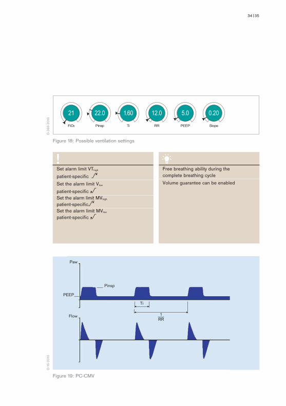
PC-CMV(PRESSURE CONTROL - CONTINUOUS MANDATORY VENTILATION)– pressure-controlled– machine-triggered– time cycled– permitted spontaneous breathing during the whole breathing cycle
(Figure 19)
The tidal volume supplied to the patient depends on the pressure difference between PEEP and Pinsp, the lung mechanics and the breathing effort of the patient.
The number of mandatory breaths is defined by the breathing frequency (RR).
The mandatory breaths are machine-triggered and not triggered by the patient.
--
34|35
FiO2 Pinsp Ti RR PEEP Slope
21 1.6022.0 12.0 5.0 0.20
Set alarm limit VThigh patient-specific >Set the alarm limit Vlow patient-specific <Set the alarm limit MVhigh patient-specific>Set the alarm limit MVlow patient-specific <
Free breathing ability during thecomplete breathing cycleVolume guarantee can be enabled
Paw
Flow
PEEP
Ti
1RR
Pinsp
D-2
60-2
010
D-1
5-20
10
Figure 18: Possible ventilation settings
Figure 19: PC-CMV

36|VENTILATION MODES IN INTENSIVE CARE | PRESSURE-CONTROLLED VENTILATION
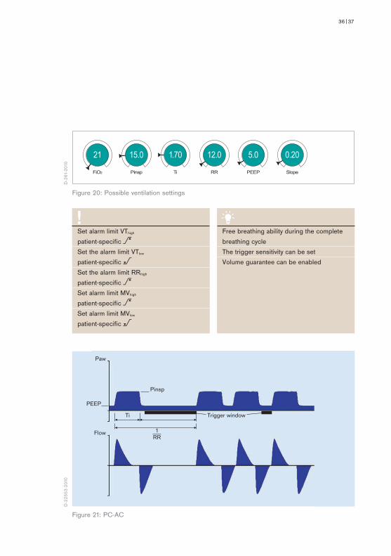
PC-AC(PRESSURE CONTROL - ASSIST CONTROL)– pressure-controlled– time cycled– machine- or patient-triggered – backup frequency– permitted spontaneous breathing during the whole breathing cycle
(Figure 21)
In PC-AC, every detected breathing attempt at PEEP level triggers a mandatory breath. The patient thus determines the number of additional mandatory breaths. In order to give the patient sufficient time for expiration, it is not possible to trigger another mandatory breath immediately after a completed breath.
If after the completion of the expiratory time no mandatory breath has been triggered, a mandatory breath is automatically applied (backup frequency). The adjuster for the Respiratory Rate (RR) therefore defines the minimum ventilation frequency.
The tidal volume (VT) results from the pressure difference between PEEP and Pinsp, the lung mechanics and the breathing effort of the patient.
If the Resistance (R) or Compliance (C) of the lung changes during the ventilation treatment, the supplied tidal volume (VT) also varies.
Because the number of mandatory breaths also depends both on the patient and the set frequency (RR), the minute volume (MV) can vary.
--
36|37
FiO2 Pinsp Ti RR PEEP Slope
21 1.70 15.0 12.0 5.0 0.20
Free breathing ability during the complete breathing cycle The trigger sensitivity can be setVolume guarantee can be enabled
Set alarm limit VThigh patient-specific >Set the alarm limit VTlow patient-specific <Set the alarm limit RRhigh patient-specific >Set alarm limit MVhigh patient-specific >Set alarm limit MVlow patient-specific <
Paw
Flow
PEEP
Pinsp
Ti
1RR
Trigger window
D-2
61-2
010
D-2
2553
-201
0
Figure 20: Possible ventilation settings
Figure 21: PC-AC

38|VENTILATION MODES IN INTENSIVE CARE | PRESSURE-CONTROLLED VENTILATION
PC-SIMV (PRESSURE CONTROL - SYNCHRONIZED INTERMITTENT MANDATORY VENTILATION)– pressure-controlled-– time cycled– machine- or patient-triggered– permitting spontaneous breathing during the whole breathing cycle
(Figure 23)
In PC-SIMV the patient can breathe spontaneously at any time, but the number of mandatory breaths is specified.
The mandatory breaths are synchronized with the patient’s own breathing attempts. A patient-triggered mandatory breath can only be triggered within a trigger window. If the expiration phase and with it the spontaneous breathing time is shortened on account of synchronization, the next expiration phase will be extended. This adaptation prevents a change in the number of mandatory breaths (RR).
If no independent breathing attempt is detected during the trigger window, the machine-triggered mandatory breath are applied.
The mandatory tidal volume (VT) results from the pressure difference between PEEP and Pinsp, the lung mechanics and the breathing effort of the patient.
If the Resistance (R) or Compliance (C) of the lung changes during the ventilation treatment, the supplied tidal volume (VT) and thus the minute volume (MV) also vary.
In this ventilation mode, the patient can breathe spontaneously during the complete breathing cycle. During spontaneous breathing at PEEP level, the patient can be supported using PS.
--

38|39
FiO2 Pinsp Ti RR PEEP ∆Psupp Slope
21 1.70 15.0 12.0 5.0 5 0.20
Paw
Flow
Trigger window for insp. synchronization
without spon- taneous breathing
with spontaneous breathing
PEEP
Pinsp
Ti
1RR
Pressure support PS
Free breathing ability during the complete breathing cycleThe trigger sensitivity can be setVolume guarantee can be enabled
Set alarm limit VThigh patient-specific >Set the alarm limit Vlow patient-specific<Set the alarm limit RRhigh patient-specific >Set alarm limit MVhigh patient-specific >Set alarm limit MVlow patient-specific <
D-2
62-2
010
D-2
1-20
10
Figure 22: Possible ventilation settings
Figure 23: PC-SIMV
40|VENTILATION MODES IN INTENSIVE CARE | PRESSURE-CONTROLLED VENTILATION
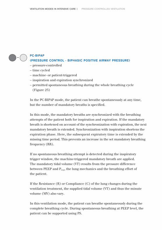
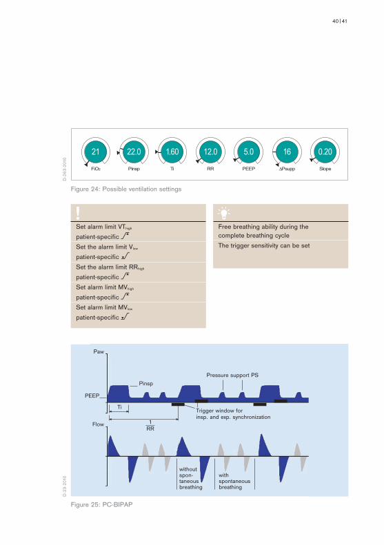
PC-BIPAP(PRESSURE CONTROL - BIPHASIC POSITIVE AIRWAY PRESSURE)– pressure-controlled– time cycled– machine- or patient-triggered– inspiration and expiration synchronized – permitted spontaneous breathing during the whole breathing cycle
(Figure 25)
In the PC-BIPAP mode, the patient can breathe spontaneously at any time, but the number of mandatory breaths is specified.
In this mode, the mandatory breaths are synchronized with the breathing attempts of the patient both for inspiration and expiration. If the mandatory breath is shortened on account of the synchronization with expiration, the next mandatory breath is extended. Synchronization with inspiration shortens the expiration phase. Here, the subsequent expiratory time is extended by the missing time period. This prevents an increase in the set mandatory breathing frequency (RR).
If no spontaneous breathing attempt is detected during the inspiratory trigger window, the machine-triggered mandatory breath are applied.The mandatory tidal volume (VT) results from the pressure difference between PEEP and Pinsp, the lung mechanics and the breathing effort of the patient.
If the Resistance (R) or Compliance (C) of the lung changes during the ventilation treatment, the supplied tidal volume (VT) and thus the minute volume (MV) also vary.
In this ventilation mode, the patient can breathe spontaneously during the complete breathing cycle. During spontaneous breathing at PEEP level, the patient can be supported using PS.
--
40|41
FiO2 Pinsp Ti RR PEEP ∆Psupp Slope
21 1.6022.0 12.0 5.0 16 0.20
Paw
Flow
Trigger window for insp. and exp. synchronization
PEEP
Pinsp
Ti
1RR
Pressure support PS
without spon- taneous breathing
with spontaneous breathing
Free breathing ability during the complete breathing cycleThe trigger sensitivity can be set
Set alarm limit VThigh patient-specific >Set the alarm limit Vlow patient-specific <Set the alarm limit RRhigh patient-specific >Set alarm limit MVhigh patient-specific >Set alarm limit MVlow patient-specific <
D-2
63-2
010
D-2
3-20
10
Figure 24: Possible ventilation settings
Figure 25: PC-BIPAP
42|VENTILATION MODES IN INTENSIVE CARE | PRESSURE-CONTROLLED VENTILATION
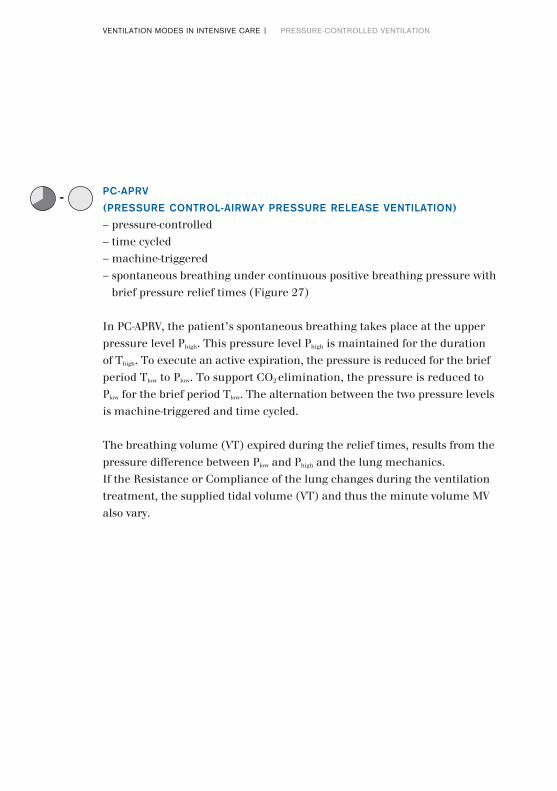
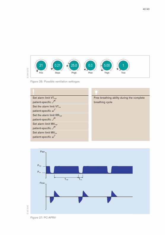
PC-APRV(PRESSURE CONTROL-AIRWAY PRESSURE RELEASE VENTILATION)– pressure-controlled– time cycled– machine-triggered– spontaneous breathing under continuous positive breathing pressure with
brief pressure relief times (Figure 27)
In PC-APRV, the patient’s spontaneous breathing takes place at the upper pressure level Phigh. This pressure level Phigh is maintained for the duration of Thigh. To execute an active expiration, the pressure is reduced for the brief period Tlow to Plow. To support CO2 elimination, the pressure is reduced to Plow for the brief period Tlow. The alternation between the two pressure levels is machine-triggered and time cycled.
The breathing volume (VT) expired during the relief times, results from the pressure difference between Plow and Phigh and the lung mechanics.If the Resistance or Compliance of the lung changes during the ventilation treatment, the supplied tidal volume (VT) and thus the minute volume MV also vary.
--
42|43
Paw
Flow
Plow
Thigh Tlow
Phigh
Free breathing ability during the complete breathing cycle
Set alarm limit VThigh patient-specific >Set the alarm limit VTlow patient-specific <Set the alarm limit RRhigh patient-specific >Set alarm limit MVhigh patient-specific >Set alarm limit MVlow patient-specific <
FiO2 Phigh Plow Thigh TlowSlope
21 25.0 0.0 5.00 10.21
D-2
64-2
010
D-2
5-20
10
Figure 26: Possible ventilation settinges
Figure 27: PC-APRV

44|VENTILATION MODES IN INTENSIVE CARE | PRESSURE-CONTROLLED VENTILATION
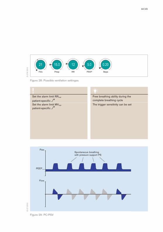
PC-PSV(PRESSURE CONTROL - PRESSURE SUPPORT VENTILATION)– pressure-controlled – machine- or patient-triggered– flow-cycled– pressure-supported – with guaranteed minimum frequency (backup frequency) (Figure 29)
In PC-PSV, the patient can breathe spontaneously at PEEP level. Every detected inspiration effort can be pressure-supported. The absolute level of pressure support is defined by Pinsp. The duration of inspiration is flow-cycled and thus depends on the lung mechanics of the patient. The patient determines the number, point of time and duration of the pressure-supported mandatory breaths.
If the breathing frequency of the patient is lower than the set backup frequency (RR) or there is no spontaneous breathing, machine-triggered flow-cycled mandatory breaths with the set pressure Pinsp are applied.
The tidal volume (VT) results from the pressure difference between PEEP and Pinsp, the lung mechanics and the breathing effort of the patient. If the Resistance (R) or Compliance (C) of the lung changes during the ventilation treatment, the supplied tidal volume (VT) and thus the minute volume (MV) also vary.
--
44|45
Paw
Flow
PEEP
Spontaneous breathing with pressure support PS
Set the alarm limit RRhigh patient-specific >Set the alarm limit MVhigh patient-specific >
Free breathing ability during the complete breathing cycleThe trigger sensitivity can be set
FiO2 Pinsp RR PEEP Slope
21 12 15.0 5.0 0.20
D-2
76-2
010
D-2
7-20
10
Figure 28: Possible ventilation settinges
Figure 29: PC-PSV

46|VENTILATION MODES IN INTENSIVE CARE | SPONTANEOUS/ASSISTED VENTILATION
During the spontaneous ventilation modes, the patient carries out the majority of the breathing effort. The pressure level PEEP (CPAP) at which spontaneous breathing takes place, can be adjusted. In all spontaneous ventilation modes, the spontaneous breaths can be supported mechanically.
To suit the respective lung mechanics, the speed of the pressure increase for PS (Pressure Support) and VS (Volume Support) can be defined using the slope or flow adjustment. Both adjustments, slope and flow, thus define the duration of the pressure increase from the lower to the higher pressure level. With the slope adjustment the time is set in seconds, with the flow adjustment the gas flow is set in liters per minute. This setting directly affects the flow and thus the supplied tidal volume (VT).
Spontaneous/assisted ventilationSPN Ventilation

46|47
FiO2 ∆PsuppPEEP Slope
21 82.9 0.20
Spontaneous breathing modesSPN-CPAP/PSSPN-CPAP/VSSPN-PPS
D-2
65-2
010
D-2
9-20
10
Figure 30: Possible ventilation settings
Figure 31: SPN-CPAP/PS
Paw
Flow
PEEP

48|VENTILATION MODES IN INTENSIVE CARE | SPONTANEOUS/ASSISTED VENTILATION
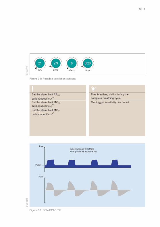
SPN-CPAP/PS (SPONTANEOUS - CONTINUOUS POSITIVE AIRWAY PRESSURE/PRESSURE SUPPORT)– spontaneous breathing – continuous positive pressure level with or without pressure support
(Figure 33)
In SPN-CPAP/PS, the patient breathes at the PEEP level. Compared to the atmospheric pressure, the airway pressure is increased during the complete breathing cycle, i.e. during inspiration and expiration. If the patient is too weak to manage the complete breathing effort independently, there is the option of pressure support (PS).
Every detected inspiration attempt at PEEP level triggers a patient-triggered, flow-cycled, pressure-supported mandatory breath. The point of time, the number and the duration of the pressure-supported breaths are determined by the patient.
If the lung mechanics of the patient change, the applied volume varies with fixed (PS).
--
48|49
FiO2 ∆PsuppPEEP Slope
21 82.9 0.20
Spontaneous breathing with pressure support PS
Paw
Flow
PEEP
Set the alarm limit RRhigh patient-specific >Set the alarm limit MVhigh patient-specific >Set the alarm limit MVlow patient-specific <
Free breathing ability during the complete breathing cycleThe trigger sensitivity can be set
D-2
65-2
010
D-2
9-20
10
Figure 32: Possible ventilation settings
Figure 33: SPN-CPAP/PS

VENTILATION MODES IN INTENSIVE CARE | SPONTANEOUS/ASSISTED VENTILATION 50|
VARIABLE PSVARIABLE PRESSURE SUPPORT– automatic variation of the pressure support (PS) in SPN-CPAP/PS
(Figure 35).
Variable PS is a form of pressure support in SPN-CPAP/PS. The basic princi-ple for pressure supported spontaneous breathing remains fully intact and is not modified.
When activating variable PS different pressure support levels are applied for each breath. First the pressure support ΔPsupp is set.
The variation of the support pressure is around the defined mean support pressure Psupp (Psupp = PEEP + ΔPsupp). The pressure vary in the range of Psupp ± ΔPsupp.
The level of variation is defined by the adjuster Press. var.. The adjustment is made in percent of the set pressure support Psupp. The variation Press. var. can be modified within a range from 0 to 100%. Due to the variation of the pressure support different ventilation pressures and therefore breathing volumes result for each breath. The level of the ventilation pressure is independent of the patient‘s breathing effort.

50|51
Press. var.
Psupp 15,0PS range min 5,0 max 25,0
∆Psupp [mbar]
100 10
Figure 34: Possible ventilation settings
Figure. 35: SPN-CPAP with Variable PS
Paw
Flow
PEEP
Variable PS during spontaneous breathing
D-3
0-20
10D
-31-
2010

VENTILATION MODES IN INTENSIVE CARE | SPONTANEOUS/ASSISTED VENTILATION 52|
SPN-CPAP/VS (SPONTANEOUS - CONTINUOUS POSITIVE AIRWAY PRESSURE/VOLUME SUPPORT)– spontaneous breathing– continuous positive pressure level – with or without volume support (Figure 37)
In SPN-CPAP/VS, the patient breathes at the PEEP level. Compared to the atmospheric pressure, the airway pressure is increased during the complete breathing cycle, i.e. during inspiration and expiration. If the patient is still too weak to manage the complete breathing effort independently, a volume support can be added. Here a target breathing volume (VT) is set and the necessary pressure for it applied.
Every detected inspiration attempt at PEEP level triggers a pressure-supported, flow-cycled ventilation breath.
If the lung mechanics change, the applied pressure varies to keep the set (VT) constant. To prevent too high pressures it is absolutely necessary to set the alarm limit Phigh.
--

52|53
FiO2 PEEPVT Slope
21 5.0520 0.20
Figure 36: Possible ventilation settings
Figure 37: SPN-CPAP/VS
Set the alarm limit Phigh patient-specific >Set the alarm limit RRhigh patient-specific >
Free breathing ability during the complete breathing cycleThe trigger sensitivity can be set
Spontaneous breathing with volume support VS
Paw
Flow
PEEP
D-2
67-2
010
D-3
3-20
10
54|VENTILATION MODES IN INTENSIVE CARE | SPONTANEOUS/ASSISTED VENTILATION
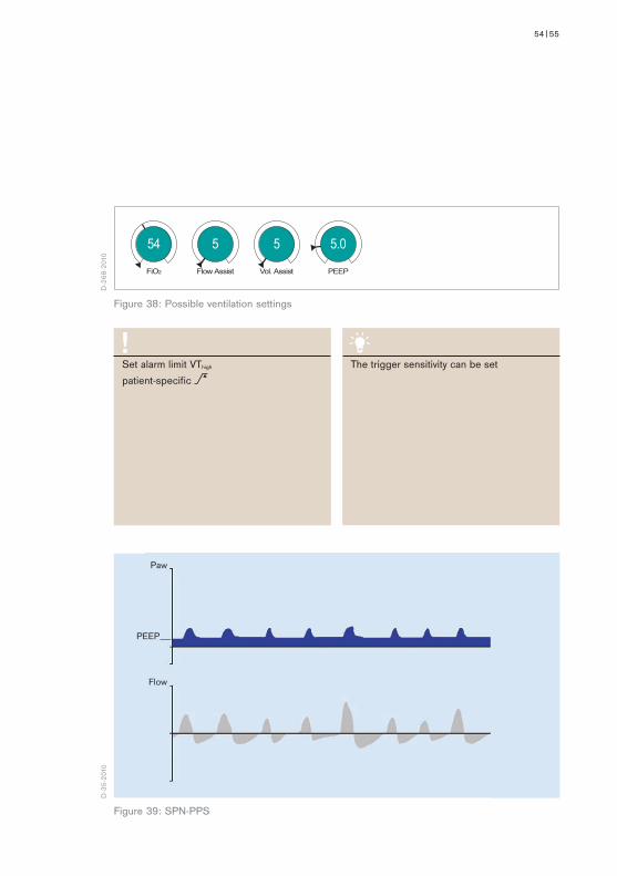
SPN-PPSSPONTANEOUS - PROPORTIONAL PRESSURE SUPPORT– spontaneous breathing– flow- and volume- proportional pressure support (Figure 39)
In SPN-PPS, a patient-triggered flow-cycled pressure support is applied proportionally to the inspiration effort of the patient, i.e. a low breathing effort is only supported mildly, whereas a stronger breathing effort triggers a larger support. The absolute level of the support depends both on the configuration of the parameters Flow Assist and Volume Assist and the patient.
The two types of pressure support, volume-proportional pressure support (volume assist) and flow-proportional pressure support (flow assist) can be used in combination. With volume assist, the elastic resistance (C) can be compensated, whereas flow assist helps overcoming the airway resistance (R).
The relationship between inspiration effort and pressure support remains constant with constant settings, whereas the pressure support varies within a breathing cycle.
--
54|55
Set alarm limit VThigh patient-specific >
The trigger sensitivity can be set
FiO2 Vol. AssistFlow Assist PEEP
54 55 5.0
Paw
Flow
PEEP
D-2
68-2
010
D-3
5-20
10
Figure 39: SPN-PPS
Figure 38: Possible ventilation settings
56|VENTILATION MODES IN INTENSIVE CARE | SPECIFIC NEONATAL VENTILATION MODES
Since the ventilation treatment for neonatals differs in parts from that for adults, specific modes are available for neonatal patients. The following modes can be used in particular for neonatal patients.
Specific neonatal ventilation modes
Specific neonatal ventilation modesSPN-CPAP (only in non-invasive ventilation, NIV)PC-HFOPC-MMV

56|57
D-3
6-20
10
58|VENTILATION MODES IN INTENSIVE CARE | SPECIFIC NEONATAL VENTILATION MODES
SPN-CPAP(SPONTANEOUS - CONTINUOUS POSITIVE AIRWAY PRESSURE)– spontaneous breathing at PEEP level – manually triggered, time-cycled, pressure-controlled breaths (Figure 41)
In SPN-CPAP, the patient breathes at the PEEP level. Compared to the atmospheric pressure, the airway pressure is increased during the complete breathing cycle, i.e. during inspiration and expiration.
The user can apply mandatory breaths by pressing a button. The constant pressure level of these mandatory breaths is set with PmanInsp. TmanInsp defines the duration of the mandatory breaths.

58|59
FiO2 PEEP Slope TmanInspPmanInsp
21 5.0 0.10 0.4315.0
Paw
PEEP
Man. insp. / hold
Spontaneous breathing Spontaneous breathing
This mode is only available for non-invasiveventilation (NIV)
D-2
69-2
010
D-3
8-20
10
Figure 40: Possible ventilation settings
Figure 41: SPN-CPAP

60|VENTILATION MODES IN INTENSIVE CARE | SPECIFIC NEONATAL VENTILATION MODES
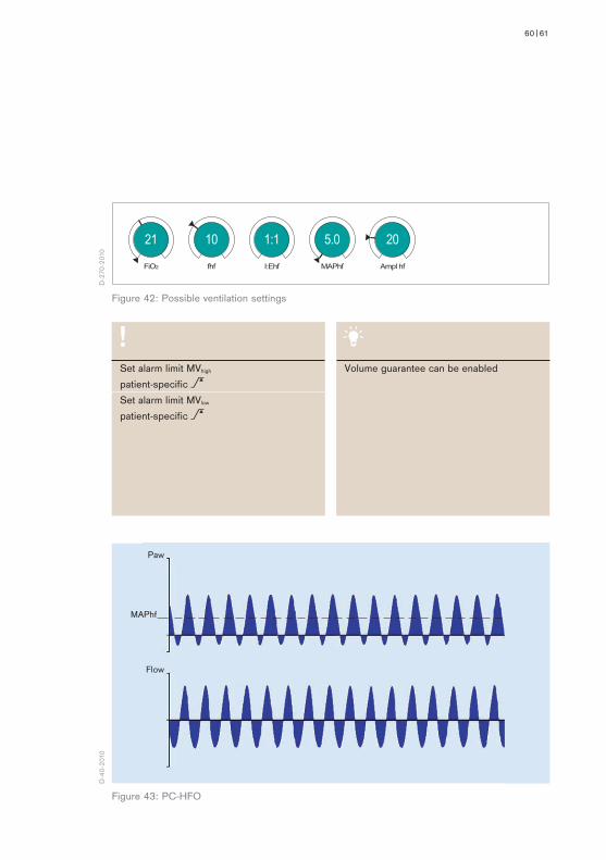
PC-HFO(PRESSURE CONTROL - HIGH FREQUENCY OSCILLATION)– pressure-controlled– high frequency oscillations at the level of the average pressure (Figure 43)
In PC-HFO, the patient is given small, very fast mandatory strokes at the level of the average pressure, so-called high-frequency pressure oscillations.
The applied breathing volumes are within the magnitude of the dead space volume and permit a gas exchange in the lung in spite of the low volumes. Whilst considerable pressure amplitudes can occur in the hose system, the pressure fluctuations in the lungs are rather minor and oscillate closely around the average pressure.
The average pressure, around which the oscillations occur, is defined by MAPhf. The pressure amplitude is defined directly via the adjustment Ampl hf.. Ampl hf is the difference between the maximum and minimum pressure of the oscillation. The frequency of the oscillations per second is set with fhf.. Depending on the frequency fhf, different I:E ratios are available for selec-tion.
Spontaneous breathing of the patient is possible at any time in PC-HFO.
60|61
FiO2 I:Ehf MAPhf Ampl hffhf
21 1:1 5.0 2010
Paw
Flow
MAPhf
Set alarm limit MVhigh patient-specific >Set alarm limit MVlow patient-specific >
Volume guarantee can be enabled
Figure 43: PC-HFO
Figure 42: Possible ventilation settings
D-2
70-2
010
D-4
0-20
10

62|VENTILATION MODES IN INTENSIVE CARE | SPECIFIC NEONATAL VENTILATION MODES
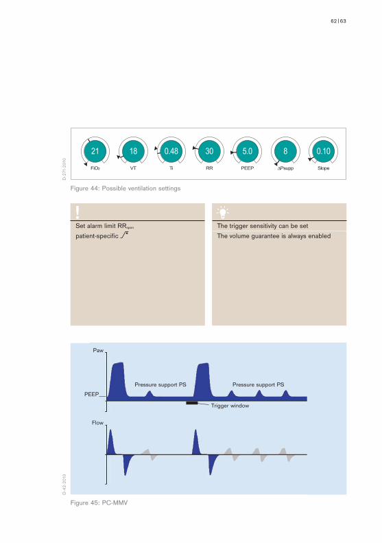
PC-MMVPRESSURE CONTROL - MANDATORY MINUTE VOLUME)– volume-guaranteed – time cycled – machine- or patient-triggered– safeguarding the mandatory minute volume with permitted spontaneous
breathing on PEEP level– volume guarantee is always enabled (Figure 45)
PC-MMV guarantees that the patient always receives at least the set minute volume MV (MV=VT*RR).
The patient can always breathe spontaneously at PEEP level. If the spontaneous breathing of the patient is insufficient to achieve the set MV, machine- triggered time cycled mandatory breaths are applied. These mandatory breaths are synchronized with the patient’s own breathing attempts.
The set breathing frequency (RR) is therefore the maximum number of mandatory breaths.
During spontaneous breathing at PEEP level, the patient can be pressure- supported using PS.
--
62|63
FiO2 VT Ti RR PEEP ∆Psupp Slope
21 0.48 18 30 5.0 8 0.10
Pressure support PS Pressure support PS
Paw
Flow
PEEP
Trigger window
Set alarm limit RRspon patient-specific >
The trigger sensitivity can be setThe volume guarantee is always enabled
D-2
71-2
010
D-4
2-20
10
Figure 44: Possible ventilation settings
Figure 45: PC-MMV

64|VENTILATION MODES IN INTENSIVE CARE | EXTENDED VENTILATION SETTINGS
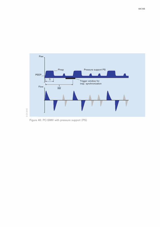
PRESSURE-SUPPORTED VENTILATION (PS)(PRESSURE SUPPORT)– pressure-supported– patient-triggered– flow-cycled mandatory breaths (Figure 46)
PS supports the spontaneous breathing effort of the patient. Every detected spontaneous inspiration attempt at PEEP level is supported with the pressure ΔPsupp. PS can be enabled in some ventilation modes.
The patient determines the start and duration of the pressure support. The level of pressure support is constant and is defined by ΔPsupp.
With PS, the speed of the pressure increase can also be defined via the slope or flow adjustment (in neonatal ventilation).
Extended ventilation settings
64|65
Figure 46: PC-SIMV with pressure support (PS)
Paw
Flow
Trigger window for insp. synchronization
PEEP
Pinsp Pressure support PS
Ti
1RR
D-2
1-20
10

66|VENTILATION MODES IN INTENSIVE CARE | NOMENCLATURE COMPARISON
Nomenclature comparison
Volume-controlled ventilation modesPrevious IPPV/ IPPVassist/ nomenclature CMV CMVassist SIMV MMVNew nomenclature VC-CMV VC-AC VC-SIMV VC-MMV
Pressure-controlled ventilation modesPrevious BIPAPassist/ BIPAP/nomenclature PCV+assist PCV+ APRVNew nomenclature C-CMV PC-AC PC-SIMV PC-BIPAP n PC-APRV PC-PSV
Spontaneous/assisted ventilation modesPrevious CPAP/ASB/nomenclature CPAP/PS PPSNewnomenclature SPN-CPAP/PS SPN-CPAP/VS SPN-PPS
VENTILATION IN INTENSIVE CARE FOR ADULTS

66|67
Pressure-controlled ventilation modesPreviousnomenclature PCV Newnomenclature Pressure Control - CMV Pressure Control – BIPAP
Spontaneous/assisted ventilation modesPreviousnomenclature Man. Spont.Newnomenclature Pressure Support - CPAP Man./Spon.
Spontaneous/assisted ventilation modesPreviousnomenclature CPAPNewnomenclature SPN-CPAP/PS SPN-CPAP/VS SPN-PPS SPN-CPAP
Pressure-controlled ventilation modesPreviousnomenclature IPPV SIPPV SIMV PSV CPAP-HFNewnomenclature PC-CMV PC-AC PC-SIMV PC-APRV PC-PSV PC-HFO PC-MMV
VENTILATION IN INTENSIVE CARE FOR NEONATAL PATIENTS
VENTILATION IN ANESTHESIA
Volume-controlled ventilation modesPreviousnomenclature IPPV SIMVNewnomenclature Volume Control - CMV Volume Control - SIMV
68|VENTILATION MODES IN INTENSIVE CARE | GLOSSARY
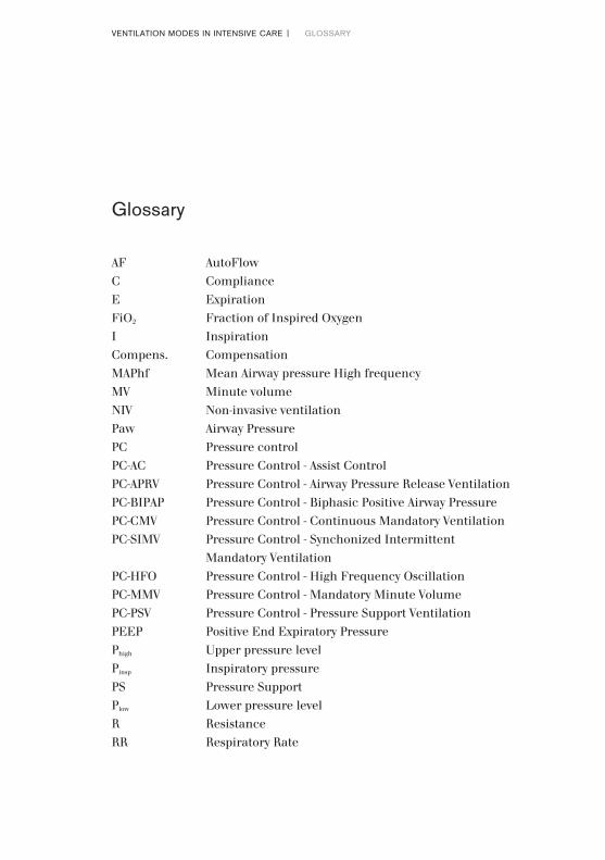
AF AutoFlowC ComplianceE ExpirationFiO2 Fraction of Inspired OxygenI Inspiration Compens. CompensationMAPhf Mean Airway pressure High frequencyMV Minute volumeNIV Non-invasive ventilationPaw Airway PressurePC Pressure control PC-AC Pressure Control - Assist ControlPC-APRV Pressure Control - Airway Pressure Release VentilationPC-BIPAP Pressure Control - Biphasic Positive Airway PressurePC-CMV Pressure Control - Continuous Mandatory VentilationPC-SIMV Pressure Control - Synchonized Intermittent
Mandatory VentilationPC-HFO Pressure Control - High Frequency OscillationPC-MMV Pressure Control - Mandatory Minute VolumePC-PSV Pressure Control - Pressure Support VentilationPEEP Positive End Expiratory Pressure Phigh Upper pressure levelPinsp Inspiratory pressurePS Pressure SupportPlow Lower pressure levelR ResistanceRR Respiratory Rate
Glossary

68|69
SPN SpontaneousSPN-CPAP/PS Spontaneous - Continuous Positive Airway Pressure/
Pressure SupportSPN-CPAP/VS Spontaneous - Continuous Positive Airway Pressure/
Volume supportSPN-PPS Spontaneous - Proportional Pressure SupportTe Expiratory timeThigh Time span during which the upper pressure level is mainta-
inedTi Inspiratory timeTlow Time span during which the lower pressure level is
maintainedVariable PS Variable Pressure SupportVC Volume control VC-AC Volume Control - Assist ControlVC-CMV Volume Control - Continuous Mandatory VentilationVC-MMV Volume Control - Mandatory Minute VolumeVC-SIMV Pressure Control - Synchronized Intermittent Mandatory
VentilationVG Volume guaranteeVT Tidal volumeΔPsupp Adjustable pressure support

VENTILATION MODES IN INTENSIVE CARE | REFERENCES 70|
[1] McPherson SP; Respiratory therapy equipment. Saint Louis: C.V. Mosby Company, 1977
[2] Downs JB, Klein EF Jr, Desautels D, Modell JH, Kirby RR; Intermittent mandatory ventilation: a new approach to weaning patients from mechanical ventilators. Chest. 1973 Sep;64(3):331-335
[3] Cairo JM, Pilbeam SP. Mosby’s respiratory care equipment. 7th edition. St. Louis. Mosby, Inc., 2004
References

70|71

90 6
6 47
7 |
15.1
1-4
| C
omm
unic
atio
ns &
Sal
es M
arke
ting
| P
P |
LE
| P
rinte
d in
Ger
man
y |
Sub
ject
to m
odifi
catio
ns |
© 2
015
Drä
gerw
erk
AG &
Co.
KG
aA
CORPORATE HEADQUARTERSDrägerwerk AG & Co. KGaAMoislinger Allee 53–5523558 Lübeck, Germany
www.draeger.com
REGION EUROPE CENTRAL AND EUROPE NORTHDrägerwerk AG & Co. KGaA Moislinger Allee 53–5523558 Lübeck, GermanyTel +49 451 882 0Fax +49 451 882 [email protected]
REGION EUROPE SOUTHDräger Médical S.A.S. Parc de Haute Technologie d’Antony 225, rue Georges Besse92182 Antony Cedex, FranceTel +33 1 46 11 56 00Fax +33 1 40 96 97 [email protected]
REGION MIDDLE EAST, AFRICADrägerwerk AG & Co. KGaABranch OfficeP.O. Box 505108Dubai, United Arab EmiratesTel +971 4 4294 600Fax +971 4 4294 [email protected]
REGION ASIA / PACIFICDraeger Medical South East Asia Pte Ltd.25 International Business Park#04-27/29 German CentreSingapore 609916, SingaporeTel +65 6572 4388Fax +65 6572 4399 [email protected]
REGION CENTRAL AND SOUTH AMERICADräger Panama Comercial S. de R.L.Complejo Business Park, V tower, 10th floorPanama CityTel +507 377 9100Fax +507 377 9130 [email protected]
Manufacturer:Drägerwerk AG & Co. KGaAMoislinger Allee 53–5523558 Lübeck, Germany
Locate your Regional Sales Representative at: www.draeger.com/contact