Embed Size (px)
Citation preview
Report No. K-TRAN: KU-15-6 ▪ FINAL REPORT▪ December 2015
Kansas Highway LED Illumination Manual: A Guide for the Use of LED Lighting Systems
Hongyi Cai, Ph.D.
The University of Kansas

i
Form DOT F 1700.7 (8-72)
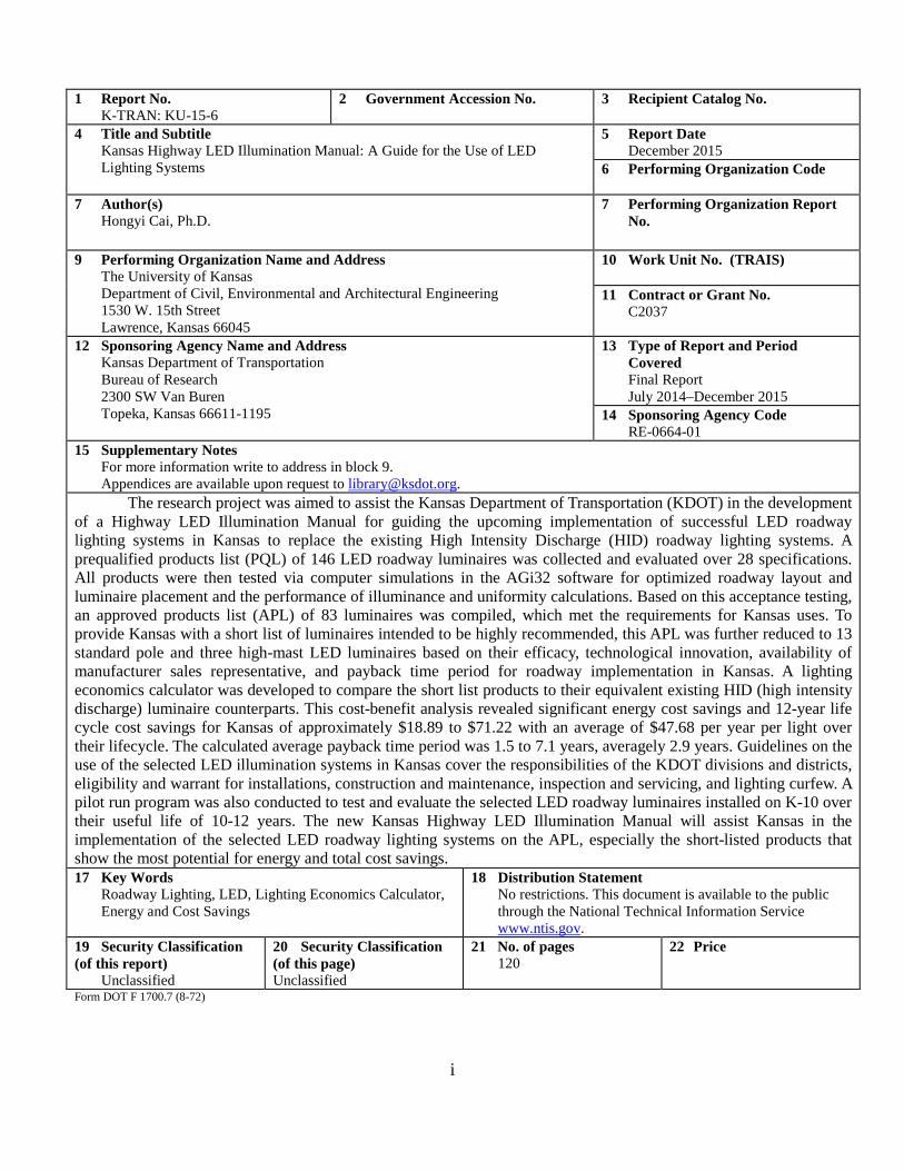
1 Report No. K-TRAN: KU-15-6
2 Government Accession No.
3 Recipient Catalog No.
4 Title and Subtitle Kansas Highway LED Illumination Manual: A Guide for the Use of LED Lighting Systems
5 Report Date December 2015
6 Performing Organization Code
7 Author(s) Hongyi Cai, Ph.D.
7 Performing Organization Report No.
9 Performing Organization Name and Address The University of Kansas Department of Civil, Environmental and Architectural Engineering 1530 W. 15th Street Lawrence, Kansas 66045
10 Work Unit No. (TRAIS)
11 Contract or Grant No. C2037
12 Sponsoring Agency Name and Address Kansas Department of Transportation Bureau of Research 2300 SW Van Buren Topeka, Kansas 66611-1195
13 Type of Report and Period Covered Final Report July 2014–December 2015
14 Sponsoring Agency Code RE-0664-01
15 Supplementary Notes For more information write to address in block 9. Appendices are available upon request to [email protected].
The research project was aimed to assist the Kansas Department of Transportation (KDOT) in the development of a Highway LED Illumination Manual for guiding the upcoming implementation of successful LED roadway lighting systems in Kansas to replace the existing High Intensity Discharge (HID) roadway lighting systems. A prequalified products list (PQL) of 146 LED roadway luminaires was collected and evaluated over 28 specifications. All products were then tested via computer simulations in the AGi32 software for optimized roadway layout and luminaire placement and the performance of illuminance and uniformity calculations. Based on this acceptance testing, an approved products list (APL) of 83 luminaires was compiled, which met the requirements for Kansas uses. To provide Kansas with a short list of luminaires intended to be highly recommended, this APL was further reduced to 13 standard pole and three high-mast LED luminaires based on their efficacy, technological innovation, availability of manufacturer sales representative, and payback time period for roadway implementation in Kansas. A lighting economics calculator was developed to compare the short list products to their equivalent existing HID (high intensity discharge) luminaire counterparts. This cost-benefit analysis revealed significant energy cost savings and 12-year life cycle cost savings for Kansas of approximately $18.89 to $71.22 with an average of $47.68 per year per light over their lifecycle. The calculated average payback time period was 1.5 to 7.1 years, averagely 2.9 years. Guidelines on the use of the selected LED illumination systems in Kansas cover the responsibilities of the KDOT divisions and districts, eligibility and warrant for installations, construction and maintenance, inspection and servicing, and lighting curfew. A pilot run program was also conducted to test and evaluate the selected LED roadway luminaires installed on K-10 over their useful life of 10-12 years. The new Kansas Highway LED Illumination Manual will assist Kansas in the implementation of the selected LED roadway lighting systems on the APL, especially the short-listed products that show the most potential for energy and total cost savings. 17 Key Words
Roadway Lighting, LED, Lighting Economics Calculator, Energy and Cost Savings
18 Distribution Statement No restrictions. This document is available to the public through the National Technical Information Service www.ntis.gov.
19 Security Classification (of this report)
Unclassified
20 Security Classification (of this page) Unclassified
21 No. of pages 120
22 Price

ii
This page intentionally left blank.
iii
Kansas Highway LED Illumination Manual: A Guide for the Use of LED Lighting Systems
Final Report
Prepared by
Hongyi Cai, Ph.D.
The University of Kansas Department of Civil, Environmental and Architectural Engineering
1530 W. 15th Street, Lawrence, Kansas 66045, USA Office: 2134-C Learned Hall
Phone: (785) 864-2597 Fax: (785) 864-5631
E-mail: [email protected]
A Report on Research Sponsored by
THE KANSAS DEPARTMENT OF TRANSPORTATION TOPEKA, KANSAS
and
THE UNIVERSITY OF KANSAS
LAWRENCE, KANSAS
December 2015
© Copyright 2015, Kansas Department of Transportation
iv
PREFACE The Kansas Department of Transportation’s (KDOT) Kansas Transportation Research and New-Developments (K-TRAN) Research Program funded this research project. It is an ongoing, cooperative and comprehensive research program addressing transportation needs of the state of Kansas utilizing academic and research resources from KDOT, Kansas State University and the University of Kansas. Transportation professionals in KDOT and the universities jointly develop the projects included in the research program.
NOTICE The authors and the state of Kansas do not endorse products or manufacturers. Trade and manufacturers names appear herein solely because they are considered essential to the object of this report. This information is available in alternative accessible formats. To obtain an alternative format, contact the Office of Public Affairs, Kansas Department of Transportation, 700 SW Harrison, 2nd Floor – West Wing, Topeka, Kansas 66603-3745 or phone (785) 296-3585 (Voice) (TDD).
DISCLAIMER The contents of this report reflect the views of the authors who are responsible for the facts and accuracy of the data presented herein. The contents do not necessarily reflect the views or the policies of the state of Kansas. This report does not constitute a standard, specification or regulation.
i
Abstract
The research project was aimed to assist the Kansas Department of Transportation
(KDOT) in the development of a Highway LED Illumination Manual for guiding the upcoming
implementation of successful LED roadway lighting systems in Kansas to replace the existing
High Intensity Discharge (HID) roadway lighting systems. A prequalified products list (PQL) of
146 LED roadway luminaires was collected and evaluated over 28 specifications. All products
were then tested via computer simulations in the AGi32 software for optimized roadway layout
and luminaire placement and the performance of illuminance and uniformity calculations. Based
on this acceptance testing, an approved products list (APL) of 83 luminaires was compiled,
which met the requirements for Kansas uses. To provide Kansas with a short list of luminaires
intended to be highly recommended, this APL was further reduced to 13 standard pole and three
high-mast LED luminaires based on their efficacy, technological innovation, availability of
manufacturer sales representative, and payback time period for roadway implementation in
Kansas. A lighting economics calculator was developed to compare the short list products to
their equivalent existing HID (high intensity discharge) luminaire counterparts. This cost-benefit
analysis revealed significant energy cost savings and 12-year life cycle cost savings for Kansas
of approximately $18.89 to $71.22 with an average of $47.68 per year per light over their
lifecycle. The calculated average payback time period was 1.5 to 7.1 years, averagely 2.9 years.
Guidelines on the use of the selected LED illumination systems in Kansas cover the
responsibilities of the KDOT divisions and districts, eligibility and warrant for installations,
construction and maintenance, inspection and servicing, and lighting curfew. A pilot run
program was also conducted to test and evaluate the selected LED roadway luminaires installed
on K-10 over their useful life of 10-12 years. The new Kansas Highway LED Illumination
Manual will assist Kansas in the implementation of the selected LED roadway lighting systems
on the APL, especially the short-listed products that show the most potential for energy and total
cost savings.
ii
Table of Contents
Abstract ............................................................................................................................................ i
Table of Contents ............................................................................................................................ ii
List of Abbreviations ...................................................................................................................... v
Glossary ......................................................................................................................................... vi
List of Tables ................................................................................................................................ vii
List of Figures ................................................................................................................................ ix
Chapter 1: Introduction ................................................................................................................... 1
Chapter 2: How to Use This Manual .............................................................................................. 4
Chapter 3: LED Roadway Lighting in General .............................................................................. 7
3.1 LED Technology and LED Roadway Luminaires ................................................................ 7
3.2 Typical Specifications of LED Roadway Luminaires .......................................................... 9
3.2.1 Wattage ........................................................................................................................ 11
3.2.2 Dimensions/Weight ...................................................................................................... 11
3.2.3 Lens .............................................................................................................................. 11
3.2.4 Mounting, Pole Height, Arm Length ........................................................................... 12
3.2.5 Luminaires per Pole and LEDs per Luminaire ............................................................ 14
3.2.6 Initial Lumens .............................................................................................................. 14
3.2.7 Luminaire Efficacy ...................................................................................................... 15
3.2.8 Correlated Color Temperature (CCT) .......................................................................... 15
3.2.9 Color Rendering Index (CRI) ...................................................................................... 18
3.2.10 Light Lateral Distribution Types ............................................................................... 19
3.2.11 Cutoff Classification .................................................................................................. 21
3.2.12 BUG Rating ............................................................................................................... 22
3.2.13 Driver ......................................................................................................................... 23
3.2.14 Dimming .................................................................................................................... 23
3.2.15 Sensors and Controls .................................................................................................. 24
3.2.16 Certificates ................................................................................................................. 25
3.2.17 IP Rating .................................................................................................................... 27
3.2.18 Life ............................................................................................................................. 27
3.3 Implementation Benefits of LED Roadway Luminaires .................................................... 29
Chapter 4: Roadway Lighting Design and Layout ....................................................................... 31
iii
4.1 Review of Roadway Lighting Systems ............................................................................... 31
4.1.1 Classification of Roadway and Pavement .................................................................... 31
4.1.2 Pole Placement Guidelines........................................................................................... 32
4.1.3 Lighting System Selection ........................................................................................... 33
4.1.4 LED Lighting System Layout and Geometry .............................................................. 35
4.1.5 Adaptive Lighting Controls ......................................................................................... 41
4.2 Lighting Design and Layout ............................................................................................... 41
4.2.1 Roadway Lighting Design Criteria .............................................................................. 41
4.2.2 Roadway Lighting Layout Computer Calculation ....................................................... 49
Chapter 5: Selection of Qualified LED Roadway Luminaires ..................................................... 51
5.1 Specifications of Qualified LED Roadway Lighting Systems ........................................... 51
5.1.1 List of Factors for Specifications ................................................................................. 51
5.1.2 Recommended Specifications for Qualified LED Roadway Luminaires .................... 53
5.2 Prequalified Product List (PQL) ......................................................................................... 56
5.3 Acceptance Testing in AGi32 ............................................................................................. 56
5.4 Approved Products List (APL) ........................................................................................... 59
5.5 Short List of Highly Recommended Products .................................................................... 59
Chapter 6: Potential Payback Evaluation ...................................................................................... 61
6.1 Introduction ......................................................................................................................... 61
6.2 Implementation Cost Analysis and Results ........................................................................ 61
Chapter 7: How to Use the Selected LED Illumination Systems in Kansas ................................. 69
7.1 Responsibilities ................................................................................................................... 69
7.1.1 Division of Transportation Planning ............................................................................ 69
7.1.2 Division of Engineering and Design ............................................................................ 70
7.1.3 Districts ........................................................................................................................ 70
7.2 Eligibility and Warrant ....................................................................................................... 72
7.2.1 Eligibility ..................................................................................................................... 72
7.2.2 Warrants ....................................................................................................................... 74
7.2.3 Submission and Process ............................................................................................... 78
7.3 Construction and Maintenance ........................................................................................... 79
7.3.1 Review and Approval of Shop Drawings .................................................................... 79
7.3.2 Pole Placement Guidelines........................................................................................... 80
7.3.3 Electrical System Requirements .................................................................................. 81
iv
7.3.4 Maintenance Considerations ........................................................................................ 82
7.4 LED Roadway Lighting Inspection and Servicing ............................................................. 83
7.5 Lighting Curfews ................................................................................................................ 84
7.5.1 Background .................................................................................................................. 84
7.5.2 Reasons for Curfews .................................................................................................... 85
7.5.3 Considerations Before Implementation ....................................................................... 86
Chapter 8: A Pilot Run Program of the Selected LED Roadway Luminaires .............................. 88
Chapter 9: Conclusions and Discussions ...................................................................................... 98
References ................................................................................................................................... 100
Appendices available upon request to [email protected]:
Appendix A: Prequalified Product List (PQL) with 146 LED Roadway Luminaires
Appendix B: Approved Products List (APL) with 83 LED Roadway Luminaires
Appendix C: Roadway LED Luminaire Short List
Appendix D: Lighting Economics Calculator
v
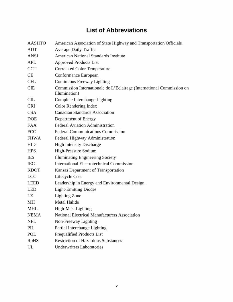
List of Abbreviations
AASHTO American Association of State Highway and Transportation Officials ADT Average Daily Traffic ANSI American National Standards Institute APL Approved Products List CCT Correlated Color Temperature CE Conformance European CFL Continuous Freeway Lighting CIE Commission Internationale de L’Eclairage (International Commission on
Illumination) CIL Complete Interchange Lighting CRI Color Rendering Index CSA Canadian Standards Association DOE Department of Energy FAA Federal Aviation Administration FCC Federal Communications Commission FHWA Federal Highway Administration HID High Intensity Discharge HPS High-Pressure Sodium IES Illuminating Engineering Society IEC International Electrotechnical Commission KDOT Kansas Department of Transportation LCC Lifecycle Cost LEED Leadership in Energy and Environmental Design. LED Light-Emitting Diodes LZ Lighting Zone MH Metal Halide MHL High-Mast Lighting NEMA National Electrical Manufacturers Association NFL Non-Freeway Lighting PIL Partial Interchange Lighting PQL Prequalified Products List RoHS Restriction of Hazardous Substances UL Underwriters Laboratories
vi
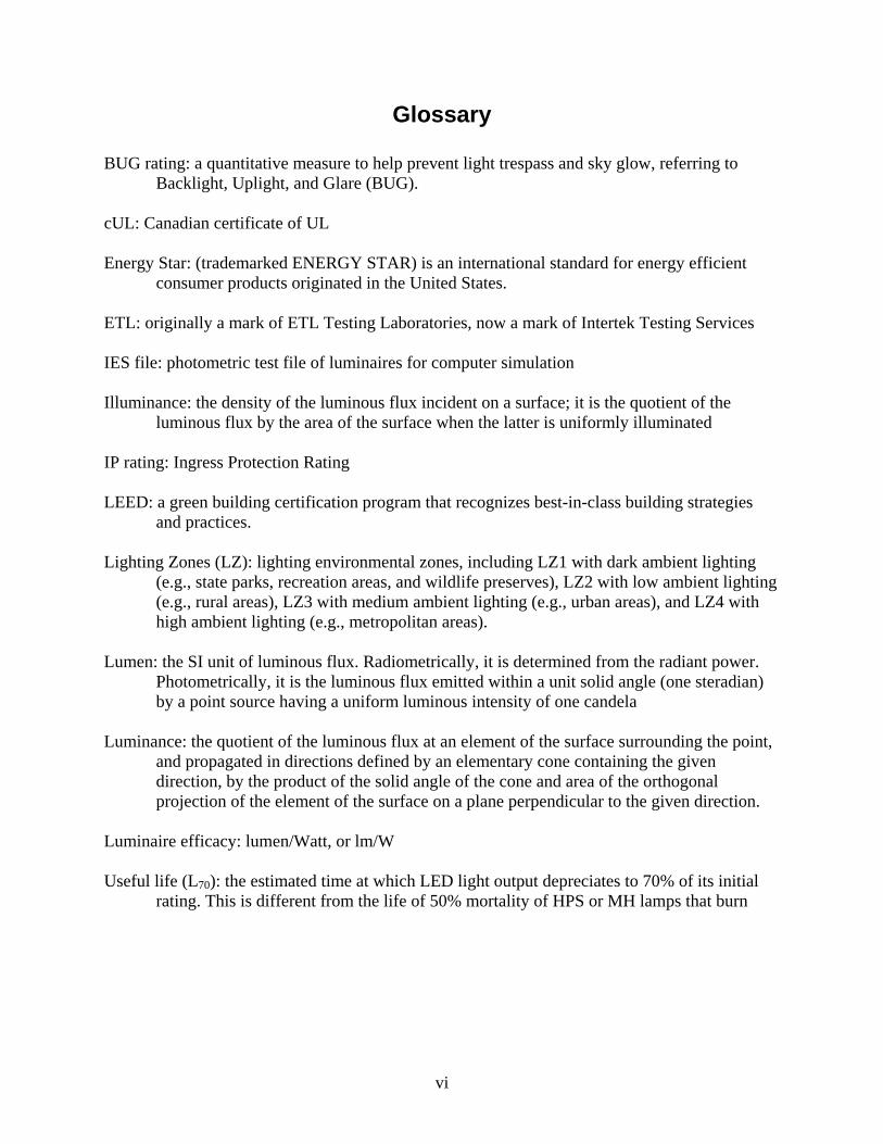
Glossary
BUG rating: a quantitative measure to help prevent light trespass and sky glow, referring to Backlight, Uplight, and Glare (BUG).
cUL: Canadian certificate of UL Energy Star: (trademarked ENERGY STAR) is an international standard for energy efficient
consumer products originated in the United States. ETL: originally a mark of ETL Testing Laboratories, now a mark of Intertek Testing Services IES file: photometric test file of luminaires for computer simulation Illuminance: the density of the luminous flux incident on a surface; it is the quotient of the
luminous flux by the area of the surface when the latter is uniformly illuminated IP rating: Ingress Protection Rating LEED: a green building certification program that recognizes best-in-class building strategies
and practices. Lighting Zones (LZ): lighting environmental zones, including LZ1 with dark ambient lighting
(e.g., state parks, recreation areas, and wildlife preserves), LZ2 with low ambient lighting (e.g., rural areas), LZ3 with medium ambient lighting (e.g., urban areas), and LZ4 with high ambient lighting (e.g., metropolitan areas).
Lumen: the SI unit of luminous flux. Radiometrically, it is determined from the radiant power.
Photometrically, it is the luminous flux emitted within a unit solid angle (one steradian) by a point source having a uniform luminous intensity of one candela
Luminance: the quotient of the luminous flux at an element of the surface surrounding the point,
and propagated in directions defined by an elementary cone containing the given direction, by the product of the solid angle of the cone and area of the orthogonal projection of the element of the surface on a plane perpendicular to the given direction.
Luminaire efficacy: lumen/Watt, or lm/W Useful life (L70): the estimated time at which LED light output depreciates to 70% of its initial
rating. This is different from the life of 50% mortality of HPS or MH lamps that burn
vii
List of Tables
Table 1: Typical Specifications of LED Roadway Luminaires as of 2015 .................................. 10
Table 2: The Certificates of LED Luminaires and Their Symbols ............................................... 26
Table 3: IP Rating Number Designations: The Meaning of the First and Second Digits ............. 28
Table 4: Pavement Classifications ................................................................................................ 32
Table 5: Typical Geometries for the Luminaire Support Systems ............................................... 38
Table 6: Recommended Illuminance and Uniformity on Road Pavement ................................... 43
Table 7: Recommended Luminance and Uniformity on Road Pavement .................................... 44
Table 8: Recommended Overall Uniformity Cross and Along the Roadway, Along the Axis of the Road Which Coincides with a Typical Driver’s Eye Position, and the Threshold Increment for Glare Compensation ................................................................................................................ 44
Table 9: Illuminance and Luminance Recommendations (Metric) .............................................. 45
Table 10: Illuminance and Luminance Recommendations (English) ........................................... 46
Table 11: Recommended Illuminance for the Intersection of Continuously Lighted Urban Streets, Based on the Values in Table 6 for R2 and R3 Pavement Classifications ................................... 47
Table 12: Spill Light Levels ......................................................................................................... 49
Table 13: Source Intensity Levels that Cause Glare ..................................................................... 49
Table 14: Required Specifications for Qualified LED Roadway Luminaires for Kansas ............ 55
Table 15: Recommended Specifications for Qualified LED Roadway Luminaires ..................... 55
Table 16: The Layout Specifications for the Four Types of Roadway Lighting in the AGi32 Simulation ..................................................................................................................................... 58
Table 17: Recommended Short List of Approved Products, All Full Cutoff and Dimmable ...... 60
Table 18: Values of Typical Factors Presumed in this Project ..................................................... 63
Table 19: APL Short List LED Luminaires Used in the Calculation with Minimum Wattages, Corresponding Initial Lumens, and Useful Life ........................................................................... 66
Table 20: Implementation Cost Analysis for the APL Short List Luminaires ............................. 67
Table 21: Eligibility Requirements for Installation of LED Lighting Systems on Different Types of Roadways in Kansas ................................................................................................................. 73
Table 22: Warranting Conditions for Continuous Freeway Lighting (CFL) ................................ 75
Table 23: Warranting Conditions for Complete Interchange Lighting (CIL) ............................... 76
Table 24: Warranting Conditions for Partial Interchange Lighting (PIL) .................................... 76
Table 25: Warranting Conditions for High-Mast Lighting (HML) .............................................. 78
Table 26: Format of the Submission for Eligibility and Warrants of a New LED Roadway Lighting Project ............................................................................................................................ 79
viii
Table 27: Selected LED Luminaires for Field Tests in the Pilot Run Program ........................... 88
Table 28: Key Photometric Specifications of the Four LED Luminaires Tested in the Pilot Run Program ......................................................................................................................................... 90
Table 29: Field Measurement Data of the High-Mast Lighting at the Intersection of K-10 & 1900th Road Before and After the Luminaire Replacement ........................................................ 92
Table 30: Field Measurement Data of the Standard Pole Cobrahead Lighting at the Intersection of K-10 & 1900th Road Before and After the Luminaire Replacement ....................................... 93
Table 31: Field Measurement Data of the High-Mast Lighting at the Intersection of K-10 & 2300th Road Before and After the Luminaire Replacement ........................................................ 93
Table 32: Field Measurement Data of the Standard Pole Cobrahead Lighting at the Intersection of K-10 & 2300th Road Before and After the Luminaire Replacement ....................................... 94
ix
List of Figures
Figure 1: Visual Comparison of HPS vs. LED Lighting ................................................................ 2
Figure 2: Different Types of Lens Commonly Specified in the Current Roadway Luminaires ... 12
Figure 3: Different Mounting of Standard and High-Mast LED Roadway Luminaires ............... 13
Figure 4: Technicians Lower the High-Mast Lights to the Ground Level for Re-Lamping ......... 13
Figure 5: The CIE 1976 Chromaticity Diagram Showing Six Isotemperature Lines Commonly Used by the LED Manufacturers .................................................................................................. 16
Figure 6: Different CCT Values and the Kelvin Color Temperature Scale Chart ........................ 17
Figure 7: The Yellowish Light of HPS Light versus the Cool White Light of LED Roadway Lights ............................................................................................................................................ 17
Figure 8: Color Rendering Performance Evaluated Using CRI Values ....................................... 18
Figure 9: Light Lateral Distribution Types of Typical Area and Roadway Lighting ................... 19
Figure 10: Cutoff of the Roadway Luminaires ............................................................................. 21
Figure 11: IES TM-15 BUG Rating Diagram, Backlight is Measured by the Amount of Light in the BL, BM, BH, and BVH Zones ................................................................................................ 22
Figure 12: LED Life L70 and the Light Diminishes Gradually Over Time versus Conventional Light Sources Which Burn Out at the End of Their Life .............................................................. 29
Figure 13: Typical Standard Pole Spacing Layout Designations ................................................. 36
Figure 14: Typical Standard Pole Spacing Layout ....................................................................... 37
Figure 15: Typical Pole Designations and the Geometries ........................................................... 39
Figure 15: Typical Pole Designations and the Geometries (Continued) ...................................... 40
Figure 16: Annualized Savings per Streetlight over its Lifecycle of 12-Years ............................ 68
Figure 17: Flow Chart of Test Procedure for Analyzing Faults in a Typical LED Lighting System....................................................................................................................................................... 83
Figure 18: Field Test Location of the Pilot Run LED Luminaires, (a) The Sites on K-10, East of Lawrence, (b) Intersection of K-10 & E 1900 Road, (c) Intersections of K-10 & E 2300 Road . 89
Figure 19: Layout of Field Measurement Points, Including Point 1-10 for High-Mast Lighting and Point 11-14 for Standard Pole Cobrahead Light, (a) Measurement Points at the Intersection of K-10 & E 1900 Road, (b) Measurement Points at the Intersections of K-10 & E 2300 Road . 91
Figure 20: Comparison of High-Mast Lighting Conditions at the Intersection of K-10 & 1900th Road Before and After the Luminaire Replacement from Metal Halide to the Cooper Galleon LED ............................................................................................................................................... 94
Figure 21: Comparison of High-Mast Lighting Conditions at the Intersection of K-10 & 2300th Road Before and After the Luminaire Replacement from Metal Halide to the Holophane HMAO-LED II ........................................................................................................................................... 95
x
Figure 22: Comparison of Standard Pole Cobrahead Lighting Conditions at the Intersection of K-10 & 1900th Road Before and After the Luminaire Replacement from HPS to the Philips RoadFocus Cobra Head-M ........................................................................................................... 95
Figure 23: Comparison of Standard Pole Cobrahead Lighting Conditions at the Intersection of K-10 & 2300th Road Before and After the Luminaire Replacement from HPS to the GE Evolve LED Roadway Scalable Specification Grade Cobrahead-ERS1 .................................................. 96
1
Chapter 1: Introduction
City sprawl and population growth result in an expansion of transport infrastructure.
More streetlights will be installed on the roads. Over the past decade, roadway illumination
systems have undergone a transformation from conventional high intensity discharge (HID)
lamps to light-emitting diodes (LED). LED roadway luminaires have six major advantages over
the conventional HID roadway luminaires, including useful life, luminaire efficacy, photometric
performance due to the low profile of the LEDs and their directional light output that are easy to
control, color rendering performance, compatibility with advanced digital controls (e.g.,
continuous dimming, motion sensor controls, photoelectrical controls), and environment
friendliness since LEDs do not contain mercury and lead.
The LED luminaires have large energy saving potential for roadway lighting. The
Department of Energy (DOE) projects that, by 2020, LED lamp efficacies will approach 170
lumens per Watt [1-3]. Meanwhile, the price of LED luminaires is dropping. The current rate of
cost decline for LED lighting systems is approximately 20% every year. This cost reduction will
lead to a greater market penetration, projecting LED technology to represent 48% of the lumen-
hour sales of the general illumination market by 2020. By 2030, white-light LEDs will have a
market share of 74% of lumen-hour sales in the U.S. and save 297 terawatt-hours in electricity
consumption [1]. Based on these promising predictions, outdoor lighting energy consumption is
expected to reduce by 15% in 2020, increasing to 40% by 2030 [1, 4]. This would result in a 3
quad savings, which is equivalent to 261 terawatt-hours of energy. This amount of energy is
enough to provide 24 million homes across the United States with their daily electrical energy
needs for the whole year use.
Reduction in electric energy consumption on road is critical for our sustainable roadway
environment. The total U.S. energy-related emissions of carbon dioxide by the electric power
sector in 2014 were a staggering 2,043 million metric tons—which is about 38% of the total U.S.
energy-related carbon dioxide emissions [5]. Switching to LEDs over the next two decades has
the potential to save the country $250 billion in energy costs [4]. This could reduce electricity
consumption by 50%, thereby avoiding 1,800 million metric tons of carbon emissions.
2
There are already cities throughout the United States that have implemented successful
LED roadway lighting systems. Los Angeles, California, is one of those. The scope of the Los
Angeles project includes 4,500 miles of illuminated roads with 210,000 total roadway
luminaires. Of the 210,000 luminaires, Los Angeles proposed replacing 140,000 luminaires with
new LED roadway luminaires in phase one of the project. The 70,000 remaining decorative
luminaires were proposed to be updated in the second phase of the project. Thirty-six (36)
months after phase one implementation in 2013, Los Angeles [6] published an update on their
LED roadway system with results as follows: 114,067 units replaced and $5,325,793 annual
electricity savings, which totals to 63.3% electricity savings compared to the pre-existing high-
pressure sodium (HPS) roadway lighting system. Before the new LED roadway lighting system
was implemented, the HPS repair and maintenance events numbered 70,000, which fell to
46,300 after the LED implementation. Also, the failure rate of LED luminaires after 36 months
was 0.2% compared to the HPS luminaires, which had a failure rate of about 10%. Based off this
information, Los Angeles expects to save $2.5 million on annual maintenance costs.
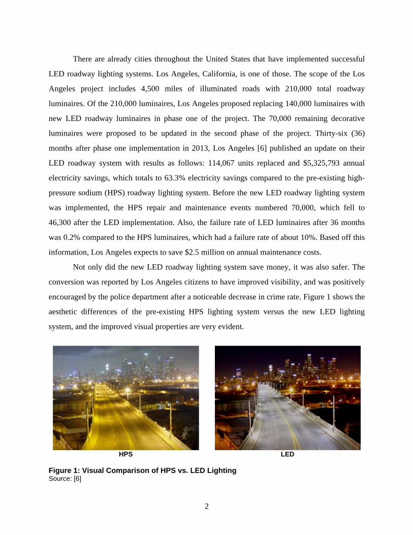
Not only did the new LED roadway lighting system save money, it was also safer. The
conversion was reported by Los Angeles citizens to have improved visibility, and was positively
encouraged by the police department after a noticeable decrease in crime rate. Figure 1 shows the
aesthetic differences of the pre-existing HPS lighting system versus the new LED lighting
system, and the improved visual properties are very evident.
HPS LED
Figure 1: Visual Comparison of HPS vs. LED Lighting Source: [6]
3
Los Angeles is not the only city to have implemented successful LED roadway lighting
programs. More and more cities across the U.S. are adopting these systems. Pretty soon, based
on the projections, LED roadway lighting is going to be the norm rather than the trendy
innovation. Street lighting can account for up to 40% of a city’s electricity bill. It is expected
that, by 2030, LEDs will replace all HID lamps used on highways and in all other transportation
illumination systems, resulting in significant reduction in electrical energy consumption and
maintenance costs.
As a result, more and more LEDs will be mounted on roads in Kansas. If Kansas were to
adopt an LED roadway lighting system, they would be doing their part to decrease emissions as
well as save money that could be utilized elsewhere. This project is intended to help the State of
Kansas Department of Transportation (KDOT) realize a new LED roadway lighting system.
The current KDOT lighting handbook that deals with HID luminaires is no longer useful
for guiding new or retrofit roadway lighting projects that deploy LED luminaires. Kansas needs a
highway LED illumination manual to evaluate the cost-effectiveness of the LED roadway
lighting systems in Kansas, judge their eligibility and warranty, guide the selection and use of
LED luminaires, and lower the maintenance costs. Many LED vendors and sales representatives
have approached the Kansas Department of Transportation (KDOT) for their LED roadway
lighting products. A new highway LED illumination manual is thus needed in Kansas.
4
Chapter 2: How to Use This Manual
This highway LED illumination manual was prepared for guiding the use of selected
qualified LED lighting systems, with a short list of highly recommended products, for not only
replacing the conventional high-intensity discharge (HID) roadway lights with LEDs in retrofit
projects but also new constructions of LED lighting projects in Kansas. The lighting specialists,
highway engineers, designers, planners, maintenance crews, and policy makers in the Kansas
Department of Transportation (KDOT), local counties, and cities in Kansas may use this manual
to guide their selection of LED roadway lighting products, their technical specifications, lighting
design and layout, lighting curfew, field construction and maintenance, inspection and servicing,
and cost-effectiveness evaluation, etc.
The manual can be divided into five major parts, as follows.
1. Fundamentals of LED roadway lighting technologies, design and layout,
and lighting criteria.
2. Selection of qualified LED roadway lighting systems, an approved
products list (APL), with a short list of highly recommended products, for
Kansas roadways.
3. Potential payback evaluation and a lighting economics calculator.
4. Guidelines on using the selected LED illumination systems in Kansas.
5. A pilot run program.
The LED technologies are upgrading on a daily basis. Although this manual focuses on
guiding the selection and installation of LED roadway luminaires currently available in the U.S.
market as of 2015 for uses on roads in Kansas, the underlying principles and the proposed
methods and techniques for testing and selection of qualified LED lighting products as well as
their cost-effectiveness analysis can be continuously used for evaluating future LED products.
However, with upgrading LED market over time, it is reasonable to assume that an update and
reaffirmation is necessary over a reasonable period of time, e.g., 10 years (or at the end of the 12-
year life cycle of current LED lighting products), when the LED technologies have undergone
break through changes.
5
In addition, the manual can be used as training materials for any personnel involved in
new and retrofit LED roadway lighting projects in Kansas. A highway LED illumination training
course on this manual will be offered in the end of this project for lighting specialists, highway
engineers, designers, planners, maintenance crews, and policy makers in KDOT and local
counties and cities in Kansas who are involved with highway illumination.
On the other hand, while this manual presents many useful outcomes, it is important to
understand that those outcomes are based upon some assumptions. Every LED roadway project
is inherently different, and without knowing the specific details of the project that KDOT or local
cities plan to undertake, this manual is intended to guide through the decision-making process in
general, rather than present a cut-and-dry design solution. The lighting economics calculator
developed in this project in particular was designed to allow changes of the design input, to tailor
the cost-benefit analysis for any project in time to come.
The assumptions and limitations of this project are outlined below, which contribute to
possible variations on how to use this manual:
The size of the actual project that KDOT or the local county/city plans to
undertake is unknown. If the project is too small, it might not have the
same benefits as larger-scale projects, as suggested in this lighting
economics calculator using a project size of 1,000 luminaires.
The manual was prepared in a general and compressive way. It is limited
by the overwhelming number of photometric test files (called IES files) of
LED roadway luminaires on the market that haven’t been tested.
Acceptance testing was mainly based on four optimized roadway layouts
of standard poles and high-mast lighting at intersections using standard
luminaire spacing solutions, and attempted to cover all common roadway
lighting plans.
6
The lighting economics calculator was based on an assumed electricity
and demand rate, energy-savings rebate rates were not taken into account,
which could have the potential to save even more money. Other
assumptions used in the calculator were based upon research studies of
projects in other states, and standard costs according to RS Means. The
variability of those assumptions with the actual KDOT project has the
potential to effect the results in small ways, if not significantly.
7
Chapter 3: LED Roadway Lighting in General
3.1 LED Technology and LED Roadway Luminaires
As a solid-state lighting source, LEDs have the following five unique characteristics that
other artificial light sources do not have.
a. Compared to traditional HID light sources used on roadways, LEDs
are very energy efficient. The energy efficacy of LEDs available in the
market as of 2015 is in a range of approximately 70-150 lumens per
watt (lm/W), versus 71-145 lm/W of high pressure sodium (HPS)
lamps, and 67-115 lm/W of metal halide (MH) lamps. In addition, the
efficacy of LEDs is still increasing with the upgrade of the LED
technologies.
b. An LED is a tiny and bright point light source, which can fit in a small
space, e.g., light-emitting surface of the roadway luminaires. This
small profile can benefit the LED roadway luminaires for more
accurate photometric performance and reduced overall size.
c. LEDs generate light towards the forward direction. LEDs also generate
a large amount of heat that is not radiated with the light but remains on
the back of the diode itself. Traditional light sources generate light and
heat in mixed energy flux towards the same direction. The LED heat
will be conducted using heat sink and dissipated to the air.
d. While an LED’s light output is not as temperature sensitive as
fluorescent, LEDs run most efficiently at a junction temperature less
than 120°C. The lower the ambient temperature, the more efficient the
LEDs. High ambient temperatures must be taken into account in the
luminaire design for heat sinking. Humidity and dirt conditions of the
environment must also be considered.
e. Most LEDs define their useful life (L70) based on the estimated time at
which LED light output depreciates to 70% of its initial rating. This is
different from the life of 50% mortality of HPS or MH lamps that burn
out.
8
Due to the unique characteristics of LEDs aforementioned, LED roadway luminaires also
have unique characteristics that are different from the HPS roadway luminaires. LED roadway
luminaires have six major advantages over the HPS luminaires, including:
a. High energy efficiency, which still increases over time with new
improvement on LED technologies. Over next decade, the LED
efficacy is predicted to reach approximately 219 lm/W by 2020 [7].
Such a high efficacy will enable a significant energy saving for
highway LED illumination.
b. Long useful life L70 (typically 50,000-100,000 hours as of 2015), over
which the light output of the LEDs gradually drops to 70% of the
initial lumen. Note that the LEDs do not burn out at the end of its
useful life, with still 70% light output remaining.
c. Good photometric performance due to the low profile and directional
light output of the LEDs, which can effectively deliver more light to
the demanded road surfaces while reducing light spill to the sky and
the surrounding environment.
d. High color rendering performance (typically CRI is 70+ as of 2015).
LEDs used for road lighting may eventually have CRI greater than 90,
similar to those LEDs used inside the buildings.
e. Compatibility with advanced digital controls, e.g., continuous
dimming controlled by occupancy sensors or photosensors to save
energy while enhancing roadway safety.
f. Environment friendliness without harmful components like mercury
and lead. Also, if well controlled, LED roadway luminaires do not
produce light pollution to the sky and light trespass to the
neighborhood.
9
On the other hand, LED roadway luminaires available in today’s market may still have
slightly higher initial cost than the conventional HPS luminaires. However, while the efficacy of
LED luminaires is increasing, their cost is dropping. It is expected that LED roadway luminaires
may be more affordable in the near future. Additionally, LED luminaires can reduce the costs in
energy consumption and maintenance over their service life, which will offset the initial costs.
3.2 Typical Specifications of LED Roadway Luminaires
Many manufacturers are available in the U.S. market to provide LED roadway lighting
systems, including luminaires and controls. Example manufacturers include Holophane, Philips,
Acuity, Cooper, GE, Hubbell, Cree, Cree Canada, HE Williams, Kenall Manufacturing Co., LSI
Industries, Sternberg Lighting, Zenaro Lighting Inc., American Electric Lighting, Selux, Stanpro
Lighting Systems, Lumca, Tersen Lighting, Sentry Electric LLC, LED Roadway Lighting Ltd.,
Excellence Opto Inc., Green Image Tech, RAB Lighting, Lighting Science, Arani, and Sansi.
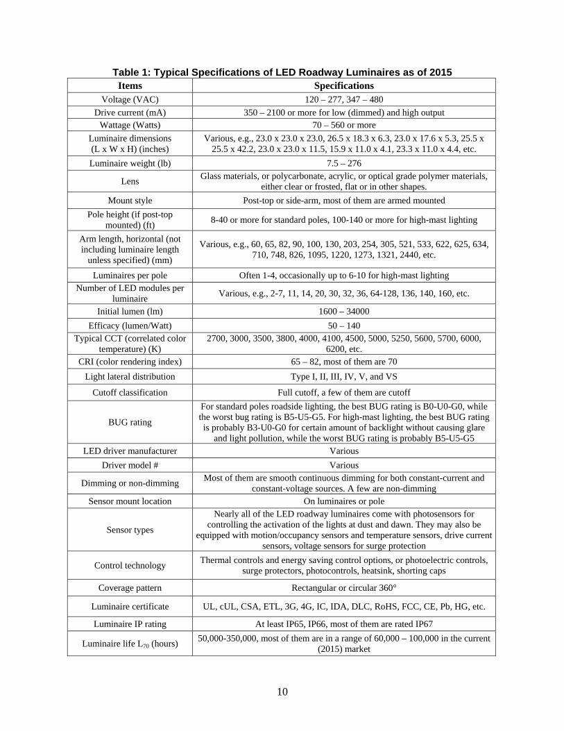
Table 1 summarizes the typical 28 specifications of LED roadway luminaires available in
the current market of 2015, including voltage, current, wattage, dimensions, weight, lens, mount
style, pole height, arm length, number of luminaires per pole, initial lumen, efficacy, CCT, CRI,
light lateral distribution, cutoff, BUG rating, sensors, control technology, certificate, IP rating,
useful life, etc., and their typical values.
10
Table 1: Typical Specifications of LED Roadway Luminaires as of 2015 Items Specifications
Voltage (VAC) 120 – 277, 347 – 480 Drive current (mA) 350 – 2100 or more for low (dimmed) and high output
Wattage (Watts) 70 – 560 or more Luminaire dimensions (L x W x H) (inches)
Various, e.g., 23.0 x 23.0 x 23.0, 26.5 x 18.3 x 6.3, 23.0 x 17.6 x 5.3, 25.5 x 25.5 x 42.2, 23.0 x 23.0 x 11.5, 15.9 x 11.0 x 4.1, 23.3 x 11.0 x 4.4, etc.
Luminaire weight (lb) 7.5 – 276
Lens Glass materials, or polycarbonate, acrylic, or optical grade polymer materials, either clear or frosted, flat or in other shapes.
Mount style Post-top or side-arm, most of them are armed mounted Pole height (if post-top
mounted) (ft) 8-40 or more for standard poles, 100-140 or more for high-mast lighting
Arm length, horizontal (not including luminaire length
unless specified) (mm)
Various, e.g., 60, 65, 82, 90, 100, 130, 203, 254, 305, 521, 533, 622, 625, 634, 710, 748, 826, 1095, 1220, 1273, 1321, 2440, etc.
Luminaires per pole Often 1-4, occasionally up to 6-10 for high-mast lighting Number of LED modules per
luminaire Various, e.g., 2-7, 11, 14, 20, 30, 32, 36, 64-128, 136, 140, 160, etc.
Initial lumen (lm) 1600 – 34000 Efficacy (lumen/Watt) 50 – 140
Typical CCT (correlated color temperature) (K)
2700, 3000, 3500, 3800, 4000, 4100, 4500, 5000, 5250, 5600, 5700, 6000, 6200, etc.
CRI (color rendering index) 65 – 82, most of them are 70 Light lateral distribution Type I, II, III, IV, V, and VS
Cutoff classification Full cutoff, a few of them are cutoff
BUG rating
For standard poles roadside lighting, the best BUG rating is B0-U0-G0, while the worst bug rating is B5-U5-G5. For high-mast lighting, the best BUG rating is probably B3-U0-G0 for certain amount of backlight without causing glare
and light pollution, while the worst BUG rating is probably B5-U5-G5 LED driver manufacturer Various
Driver model # Various
Dimming or non-dimming Most of them are smooth continuous dimming for both constant-current and constant-voltage sources. A few are non-dimming
Sensor mount location On luminaires or pole
Sensor types
Nearly all of the LED roadway luminaires come with photosensors for controlling the activation of the lights at dust and dawn. They may also be
equipped with motion/occupancy sensors and temperature sensors, drive current sensors, voltage sensors for surge protection
Control technology Thermal controls and energy saving control options, or photoelectric controls, surge protectors, photocontrols, heatsink, shorting caps
Coverage pattern Rectangular or circular 360°
Luminaire certificate UL, cUL, CSA, ETL, 3G, 4G, IC, IDA, DLC, RoHS, FCC, CE, Pb, HG, etc.
Luminaire IP rating At least IP65, IP66, most of them are rated IP67
Luminaire life L70 (hours) 50,000-350,000, most of them are in a range of 60,000 – 100,000 in the current (2015) market
11
More details of the specifications are expounded as follows.
3.2.1 Wattage
Wattage of the LED roadway luminaires is the SI unit of power, equivalent to one joule
per second. LEDs require less power to operate. Therefore, the corresponding wattage of LED
roadway luminaires is a lot lower than that of the conventional HPS roadway standard pole and
high-mast lighting luminaires commonly used on Kansas roads.
As shown in Table 1, the LED roadway luminaires available in the current market run on
different voltages, typically from 120-277 or 347-480 VAC. The drive current also varies
approximately from 350-2100 mA or more for low (dimmed) light output or high output (non-
dimmed). The wattage of the LED roadway luminaires available in the market is in a wide range
of 70-560 Watts or more.
3.2.2 Dimensions/Weight
For each LED roadway luminaire, it is important to record its dimensions and weight as
input information for shipping, field installation, and maintenance. Typically, the bigger and
heavier the luminaire will result in a higher cost for shipping and installation costs up front.
LEDs are tiny and bright light sources, thus, LED roadway luminaires could be made much
smaller than the HPS luminaires without compromising their photometric performance.
The LED roadway luminaires available in the current market have different sizes, e.g.,
23.0” x 23.0” x 23.0” (584 mm x 584 mm x 584 mm), 26.5” x 18.3” x 6.3” (674 mm x 466 mm x
161 mm), 23.0” x 17.6” x 5.3” (584 mm x 447 mm x 135 mm), 25.5” x 25.5” x 42.2” (648 mm x
648 mm x 1072 mm), 23.0” x 23.0” x 11.5” (584 mm x 584 mm x 291 mm), 15.9” x 11.0” x 4.1”
(404 mm x 280 mm x 104 mm), 23.3” x 11.0” x 4.4” (591 mm x 279 mm x 111 mm), etc. The
weight of the luminaires also varies from 7.5-276 pounds.
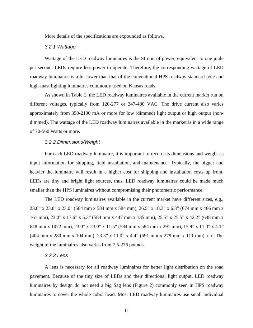
3.2.3 Lens
A lens is necessary for all roadway luminaires for better light distribution on the road
pavement. Because of the tiny size of LEDs and their directional light output, LED roadway
luminaires by design do not need a big Sag lens (Figure 2) commonly seen in HPS roadway
luminaires to cover the whole cobra head. Most LED roadway luminaires use small individual
12
lens covering each LED, or a whole piece of flat lens (Figure 2) to cover the entire light-emitting
surface of the LED luminaire. Flat lenses are flush with the outside metal casing, while sag
lenses drop below. The different sag choices allow for different distribution angles.
Sag lens Flat lens Individual lens on each LED module
Figure 2: Different Types of Lens Commonly Specified in the Current Roadway Luminaires
The lens of the LED roadway luminaires may be glass, polycarbonate, acrylic, or optical
grade polymer materials, either clear or frosted, flat or in other shapes. Most luminaires available
in the current market specify acrylic or polycarbonate lenses. These lenses prove to be more
durable than the traditional glass lenses. There are also some lenses in the list that are specified
as prismatic. Prismatic lenses provide economy and efficiency but only limited control of light
distribution—the majority of the light is directed downward within a given distribution, but a
portion of the light is refracted into the higher angles.
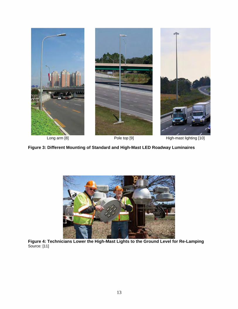
3.2.4 Mounting, Pole Height, Arm Length
The mounting style of the LED luminaires includes post-top or arm mounted, and most of
them are arm mounted. Nearly all LED roadway luminaires are specified on poles with varying
arm lengths, as shown in Figure 3. The pole height and arm length vary between luminaires,
especially between standard versus high-mast luminaires. The arm length is the dimension from
the pole to the luminaire, which helps place the light closer to the target surface—the road
pavement. The mounting of roadway luminaires is fairly standard, with the head of the luminaire
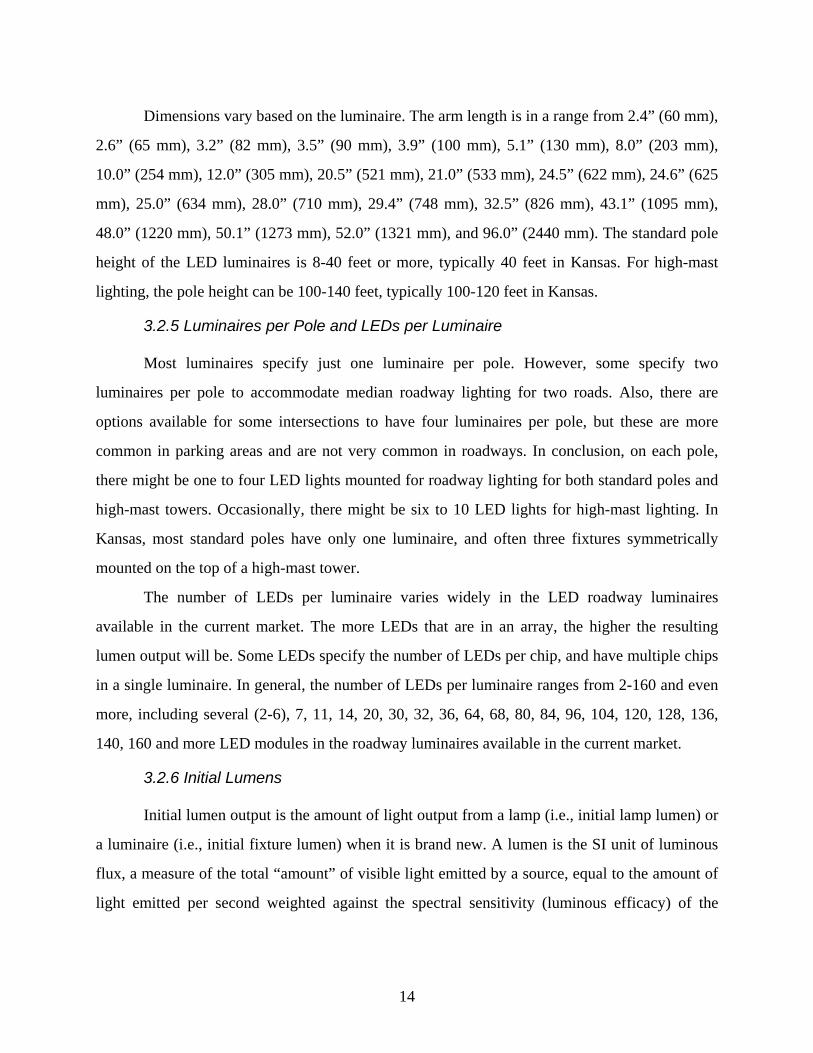
facing directly towards the ground, illuminating the roadway. Figure 4 also shows the high-mast
lights lowered to the ground level for re-lamping.
13
Long arm [8] Pole top [9] High-mast lighting [10]
Figure 3: Different Mounting of Standard and High-Mast LED Roadway Luminaires
Figure 4: Technicians Lower the High-Mast Lights to the Ground Level for Re-Lamping Source: [11]
14
Dimensions vary based on the luminaire. The arm length is in a range from 2.4” (60 mm),
2.6” (65 mm), 3.2” (82 mm), 3.5” (90 mm), 3.9” (100 mm), 5.1” (130 mm), 8.0” (203 mm),
10.0” (254 mm), 12.0” (305 mm), 20.5” (521 mm), 21.0” (533 mm), 24.5” (622 mm), 24.6” (625
mm), 25.0” (634 mm), 28.0” (710 mm), 29.4” (748 mm), 32.5” (826 mm), 43.1” (1095 mm),
48.0” (1220 mm), 50.1” (1273 mm), 52.0” (1321 mm), and 96.0” (2440 mm). The standard pole
height of the LED luminaires is 8-40 feet or more, typically 40 feet in Kansas. For high-mast
lighting, the pole height can be 100-140 feet, typically 100-120 feet in Kansas.
3.2.5 Luminaires per Pole and LEDs per Luminaire
Most luminaires specify just one luminaire per pole. However, some specify two
luminaires per pole to accommodate median roadway lighting for two roads. Also, there are
options available for some intersections to have four luminaires per pole, but these are more
common in parking areas and are not very common in roadways. In conclusion, on each pole,
there might be one to four LED lights mounted for roadway lighting for both standard poles and
high-mast towers. Occasionally, there might be six to 10 LED lights for high-mast lighting. In
Kansas, most standard poles have only one luminaire, and often three fixtures symmetrically
mounted on the top of a high-mast tower.
The number of LEDs per luminaire varies widely in the LED roadway luminaires
available in the current market. The more LEDs that are in an array, the higher the resulting
lumen output will be. Some LEDs specify the number of LEDs per chip, and have multiple chips
in a single luminaire. In general, the number of LEDs per luminaire ranges from 2-160 and even
more, including several (2-6), 7, 11, 14, 20, 30, 32, 36, 64, 68, 80, 84, 96, 104, 120, 128, 136,
140, 160 and more LED modules in the roadway luminaires available in the current market.
3.2.6 Initial Lumens
Initial lumen output is the amount of light output from a lamp (i.e., initial lamp lumen) or
a luminaire (i.e., initial fixture lumen) when it is brand new. A lumen is the SI unit of luminous
flux, a measure of the total “amount” of visible light emitted by a source, equal to the amount of
light emitted per second weighted against the spectral sensitivity (luminous efficacy) of the
15
human eye. The initial lumen of the LED luminaires available in the current market as of 2015 is
in a range from 1,600-34,000 lumen.
3.2.7 Luminaire Efficacy
The efficacy of LED roadway luminaires is measured as the total initial fixture lumens
per Watt (lm/W). Compared to traditional HID roadway luminaires commonly used on roads in
Kansas, LED roadway luminaires are very energy efficient. When comparing the efficacy for
LED and conventional products, it is vital to consider the system as a whole. The efficacy of
LED roadway luminaires considers the entire lighting system including driver, thermal, and optic
losses. The average efficacy of LED roadway luminaires was around 80 lm/W in mid-2013, but
is now closer to 100 lm/W, according to the U.S. Energy Information Administration. In the
current market of 2015, the efficacy of LED luminaires is in a range from 50-140 lm/W.
Moreover, LED roadway luminaires is expected to make substantial increases in efficacy in the
near future when the LED efficacy is predicted to reach 219 lm/W over the next decades [7].
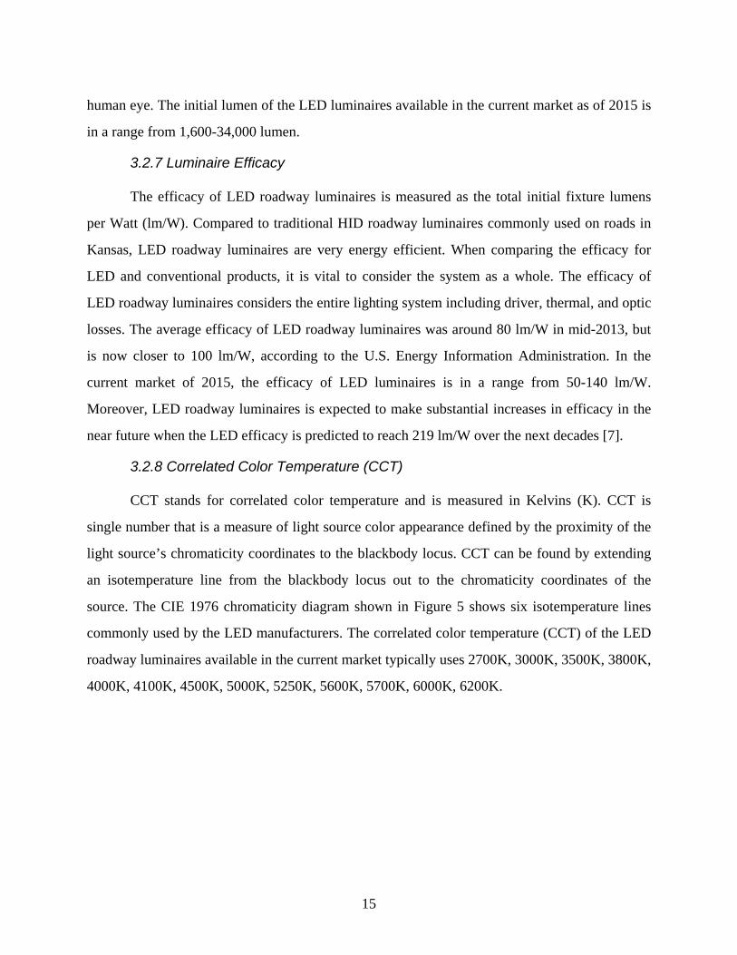
3.2.8 Correlated Color Temperature (CCT)
CCT stands for correlated color temperature and is measured in Kelvins (K). CCT is
single number that is a measure of light source color appearance defined by the proximity of the
light source’s chromaticity coordinates to the blackbody locus. CCT can be found by extending
an isotemperature line from the blackbody locus out to the chromaticity coordinates of the
source. The CIE 1976 chromaticity diagram shown in Figure 5 shows six isotemperature lines
commonly used by the LED manufacturers. The correlated color temperature (CCT) of the LED
roadway luminaires available in the current market typically uses 2700K, 3000K, 3500K, 3800K,
4000K, 4100K, 4500K, 5000K, 5250K, 5600K, 5700K, 6000K, 6200K.
16
Figure 5: The CIE 1976 Chromaticity Diagram Showing Six Isotemperature Lines Commonly Used by the LED Manufacturers Source: [12]
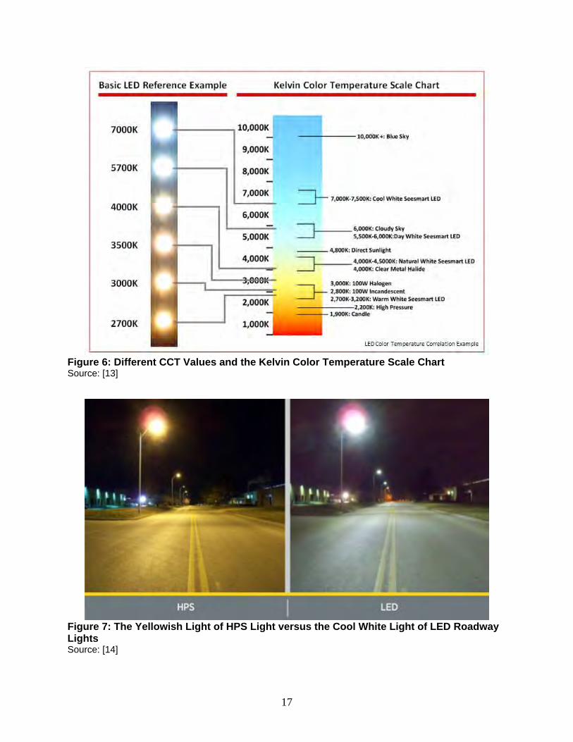
Also, as seen in Figure 6, a higher CCT color temperature in Kelvin results in a light that
is “cooler,” casting a cool light toward the bluish end on objects, while a lower CCT color
temperature in Kelvin results in a light that is “warmer,” casting a warmer light toward the
yellowish end on objects. Most LED roadway luminaires cast a much cooler light on the road
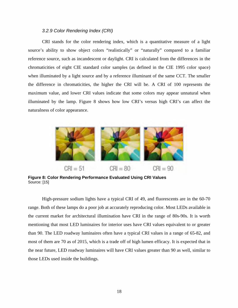
pavement compared to conventional HPS lights which emit yellow light, as shown in Figure 7.
On the other hand, the cool white LED roadway lights have spectrum that contains more
short wavelength (“blue”) light component which will largely enhance the mesopic vision of
roadway environment at night under low light levels (e.g., 0.5-1 fc). As a result, the drivers and
pedestrians can actually see better under the LED lighting even at the same light levels on the
pavement as that under the conventional HPS lights.
17
Figure 6: Different CCT Values and the Kelvin Color Temperature Scale Chart Source: [13]
Figure 7: The Yellowish Light of HPS Light versus the Cool White Light of LED Roadway Lights Source: [14]
18
3.2.9 Color Rendering Index (CRI)
CRI stands for the color rendering index, which is a quantitative measure of a light
source’s ability to show object colors “realistically” or “naturally” compared to a familiar
reference source, such as incandescent or daylight. CRI is calculated from the differences in the
chromaticities of eight CIE standard color samples (as defined in the CIE 1995 color space)
when illuminated by a light source and by a reference illuminant of the same CCT. The smaller
the difference in chromaticities, the higher the CRI will be. A CRI of 100 represents the
maximum value, and lower CRI values indicate that some colors may appear unnatural when
illuminated by the lamp. Figure 8 shows how low CRI’s versus high CRI’s can affect the
naturalness of color appearance.
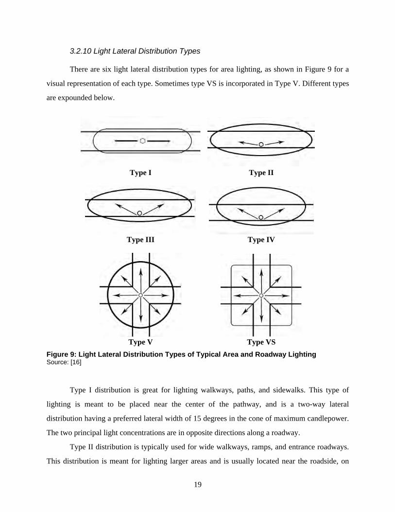
Figure 8: Color Rendering Performance Evaluated Using CRI Values Source: [15]
High-pressure sodium lights have a typical CRI of 49, and fluorescents are in the 60-70
range. Both of these lamps do a poor job at accurately reproducing color. Most LEDs available in
the current market for architectural illumination have CRI in the range of 80s-90s. It is worth
mentioning that most LED luminaires for interior uses have CRI values equivalent to or greater
than 90. The LED roadway luminaires often have a typical CRI values in a range of 65-82, and
most of them are 70 as of 2015, which is a trade off of high lumen efficacy. It is expected that in
the near future, LED roadway luminaires will have CRI values greater than 90 as well, similar to
those LEDs used inside the buildings.
19
3.2.10 Light Lateral Distribution Types
There are six light lateral distribution types for area lighting, as shown in Figure 9 for a
visual representation of each type. Sometimes type VS is incorporated in Type V. Different types
are expounded below.
Type I
Type II
Type III
Type IV
Type V Type VS
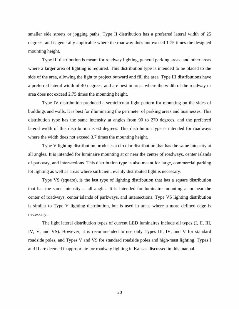
Figure 9: Light Lateral Distribution Types of Typical Area and Roadway Lighting Source: [16]
Type I distribution is great for lighting walkways, paths, and sidewalks. This type of
lighting is meant to be placed near the center of the pathway, and is a two-way lateral
distribution having a preferred lateral width of 15 degrees in the cone of maximum candlepower.
The two principal light concentrations are in opposite directions along a roadway.
Type II distribution is typically used for wide walkways, ramps, and entrance roadways.
This distribution is meant for lighting larger areas and is usually located near the roadside, on
20
smaller side streets or jogging paths. Type II distribution has a preferred lateral width of 25
degrees, and is generally applicable where the roadway does not exceed 1.75 times the designed
mounting height.
Type III distribution is meant for roadway lighting, general parking areas, and other areas
where a larger area of lighting is required. This distribution type is intended to be placed to the
side of the area, allowing the light to project outward and fill the area. Type III distributions have
a preferred lateral width of 40 degrees, and are best in areas where the width of the roadway or
area does not exceed 2.75 times the mounting height.
Type IV distribution produced a semicircular light pattern for mounting on the sides of
buildings and walls. It is best for illuminating the perimeter of parking areas and businesses. This
distribution type has the same intensity at angles from 90 to 270 degrees, and the preferred
lateral width of this distribution is 60 degrees. This distribution type is intended for roadways
where the width does not exceed 3.7 times the mounting height.
Type V lighting distribution produces a circular distribution that has the same intensity at
all angles. It is intended for luminaire mounting at or near the center of roadways, center islands
of parkway, and intersections. This distribution type is also meant for large, commercial parking
lot lighting as well as areas where sufficient, evenly distributed light is necessary.
Type VS (square), is the last type of lighting distribution that has a square distribution
that has the same intensity at all angles. It is intended for luminaire mounting at or near the
center of roadways, center islands of parkways, and intersections. Type VS lighting distribution
is similar to Type V lighting distribution, but is used in areas where a more defined edge is
necessary.
The light lateral distribution types of current LED luminaires include all types (I, II, III,
IV, V, and VS). However, it is recommended to use only Types III, IV, and V for standard
roadside poles, and Types V and VS for standard roadside poles and high-mast lighting. Types I
and II are deemed inappropriate for roadway lighting in Kansas discussed in this manual.
21
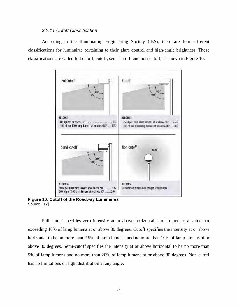
3.2.11 Cutoff Classification
According to the Illuminating Engineering Society (IES), there are four different
classifications for luminaires pertaining to their glare control and high-angle brightness. These
classifications are called full cutoff, cutoff, semi-cutoff, and non-cutoff, as shown in Figure 10.
Figure 10: Cutoff of the Roadway Luminaires Source: [17]
Full cutoff specifies zero intensity at or above horizontal, and limited to a value not
exceeding 10% of lamp lumens at or above 80 degrees. Cutoff specifies the intensity at or above
horizontal to be no more than 2.5% of lamp lumens, and no more than 10% of lamp lumens at or
above 80 degrees. Semi-cutoff specifies the intensity at or above horizontal to be no more than
5% of lamp lumens and no more than 20% of lamp lumens at or above 80 degrees. Non-cutoff
has no limitations on light distribution at any angle.
22
The cutoff classification for nearly all LED roadway luminaires is “full cutoff,” and a few
of them are “cutoff.” In this project we will only suggest luminaires that are full cutoff in order
to preserve the darkness of the night sky, preventing light pollution and sky glow.
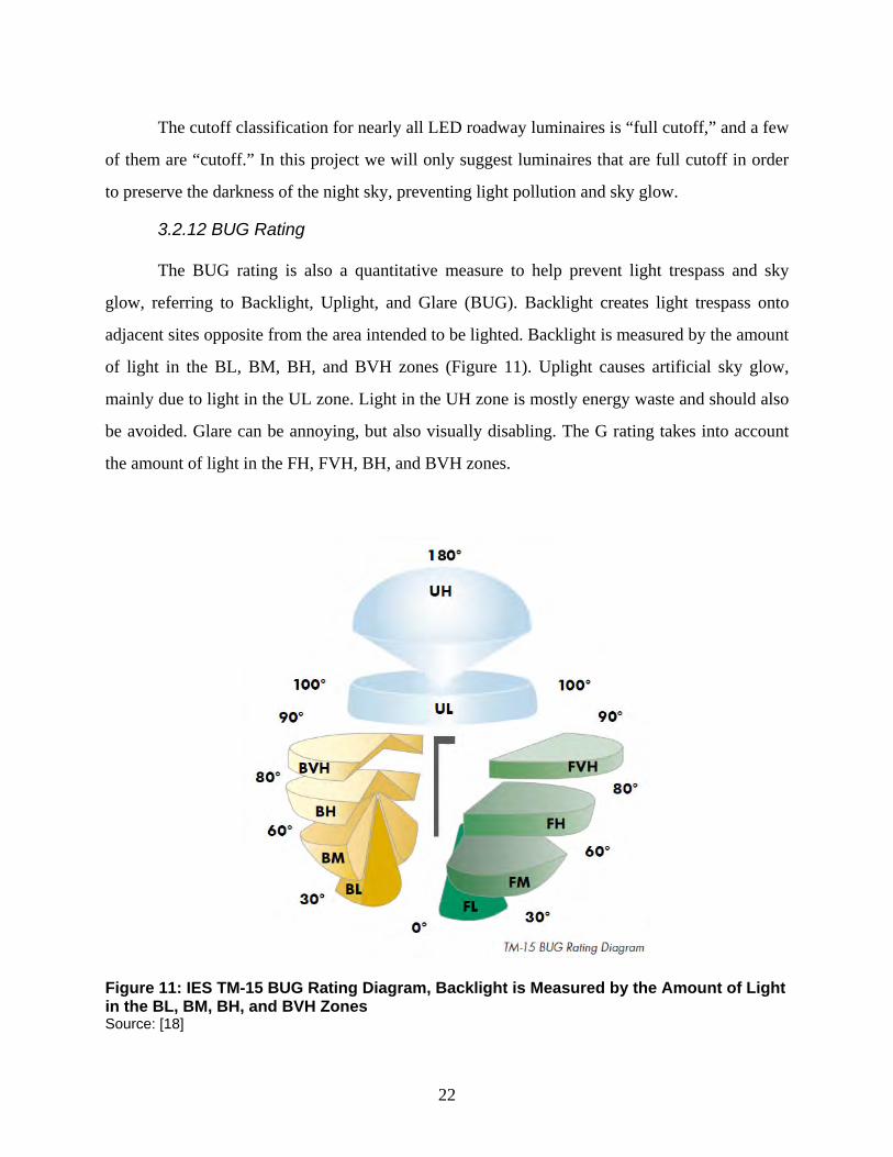
3.2.12 BUG Rating
The BUG rating is also a quantitative measure to help prevent light trespass and sky
glow, referring to Backlight, Uplight, and Glare (BUG). Backlight creates light trespass onto
adjacent sites opposite from the area intended to be lighted. Backlight is measured by the amount
of light in the BL, BM, BH, and BVH zones (Figure 11). Uplight causes artificial sky glow,
mainly due to light in the UL zone. Light in the UH zone is mostly energy waste and should also
be avoided. Glare can be annoying, but also visually disabling. The G rating takes into account
the amount of light in the FH, FVH, BH, and BVH zones.
Figure 11: IES TM-15 BUG Rating Diagram, Backlight is Measured by the Amount of Light in the BL, BM, BH, and BVH Zones Source: [18]
23
The BUG rating itself is based on zonal lumen calculations for secondary solid angles
defined in the Addendum A for the IES publication TM-15-11 [19]. The zonal lumen thresholds
are based on data from photometric testing procedures approved by IES for outdoor luminaires
(LM-31 or LM-35).
For standard poles roadside lighting, the best BUG rating is B0-U0-G0, while the worst
bug rating is B5-U5-G5. For high-mast lighting, the best BUG rating is probably B3-U0-G0 for a
certain amount of backlight without causing glare and light pollution, while the worst BUG
rating is probably B5-U5-G5.
3.2.13 Driver
An LED driver is a device that manages power and controls the current flow for an LED
lighting product. Because LED doesn’t require high voltage, LEDs could even use batteries or
solar power, depending on the application. An important factor that affects the choice of a
particular driver is the way in which multiple LEDs are actually wired together.
The three wiring configurations are: series, parallel, and series/parallel. Series refers to
LEDs connected to form a chain, cathode to anode. Parallel refers to LEDs that are connected so
as all cathodes are connected together and all anodes are connected together. The mixture of the
two in series/parallel is when LEDs are connected in series to form a chain and then the chains
are wired in parallel. There are three LED driver topologies (the way in which electronic parts
are interrelated) that are typically used. “Buck” is stepping down a higher input voltage to a
lower output voltage. “Boost” is stepping up an input voltage to a higher output voltage.
“Buck/Boost” allows the input voltage to vary—it can be greater than, less than, or equal to the
output voltage.
3.2.14 Dimming
There are drivers available that can dim LEDs from 100% to 1% output, offering smooth
continuous dimming for both constant-current and constant-voltage sources. The dimming range
of a product, either a lamp or a fixture, is based solely on the driver, including the low-end light
level performance. Choosing the right dimming control allows for the reduction of flicker, pop-
on, or drop-out. All dimmers are related to a maximum load in volts, amps, and/or Watts that
24
must not be exceeded. Similarly, some LED drivers may not perform well if they are required to
control a very minimal load. While a few of the LED roadway luminaires are non-dimming,
most of them are dimmable, which is optimal for controls, and nearly all of the LED roadway
luminaires come with photosensors for controlling the on-and-off of the lights at dust and dawn.
3.2.15 Sensors and Controls
Daylight photosensors can be used to detect the prevailing light levels, allowing the
luminaire to be turned on only when daylight levels are not adequate. Photosensors can be used
to adjust the electric lighting based on the available daylight in the space. In an open-loop
system, the photosensor detects the amount of available daylight only, and can be positioned on
the luminaire facing the daylight. In a closed-loop system, the photosensor detects the total
photometric amount of light, from both daylight and electric sources in the space. For this
reason, most roadway luminaires are installed in an open-loop system. These daylighting
photosensors have significant potential to save energy in a typical roadway lighting system.
Occupancy sensors are control devices that detect occupancy of a space by people and
turns lights on or off automatically. These sensors are typically intended for use in indoor spaces,
and are not very practical for roadway lighting applications. The occupancy sensors have three
control technologies, as follows.
a. Passive infrared control technology works on heat movement and
detection, calibrated to detect infrared radiation radiated by the human
body. Based on this detection, the sensor operates and starts lighting
loads connected to it.
b. Ultrasonic control technology is similar to radar—it works on the
Doppler shift principle. It will send high frequency sound waves in an
area and will check for their reflected patterns. If the reflected pattern
is changing continuously, then it assumes that there is occupancy and
the lighting load is turned on. If the reflected pattern is the same for a
present time then it assumes there is no occupancy and the lighting
load is switched off.
25
c. Dual technology sensors combining both passive infrared and
ultrasonic are usually the most effective way of controlling lighting
loads. However, as previously stated, this type of occupancy sensor is
not very ideal for roadway lighting.
There are different types of coverage patterns for lighting sensors, the most common are
circular and rectangular. It is important for the coverage patterns of luminaires to overlap,
ensuring that there are no areas that are not covered. The rectangular coverage pattern would be
most useful for roadway luminaires.
Nearly all of the LED roadway luminaires come with photosensors for controlling the on-
and-off of the lights at dust and dawn. They may also be equipped with motion/occupancy
sensors and temperature sensors, drive current sensors, and voltage sensors for surge protection.
The controllers use thermal controls and energy saving control options, or photoelectric controls,
surge protectors, photocontrols, heatsink, and shorting caps. The coverage patterns of those
sensors are either rectangular or 360° circular.
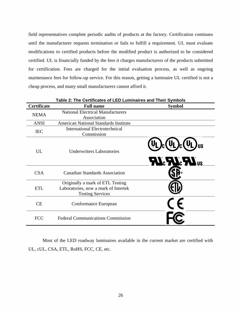
3.2.16 Certificates
LED roadway luminaires, as well as other traditional ones, are required to meet the
general requirements of certificate, including NEMA, ANSI, IEC, Underwrite (e.g., UL, CSA,
ETL, CE, FCC), LEED, ENERGY STAR, and IP rating. Their full names and symbols are listed
in Table 2.
In the U.S., the most common and important type of luminaire certification is UL. UL
operates under its own authority as an independent, not-for-profit, nongovernmental
organization. To establish certification, samples of a product submitted by manufacturers for
certification are tested and evaluated. If UL decides the product fulfills all applicable
requirements, it authorizes the manufacturer to apply a certification mark to production of the
samples submitted, or issues a certificate or notification that the product is now certified by UL.
If only a component of a product is tested by UL, an UL affiliated “ ” certificate is awarded to
the manufacturer for labeling that component.
A report of the evaluation is provided to the manufacturer, and before the manufacturer
releases products with the certification mark, UL must initiate follow-up service in which UL
26
field representatives complete periodic audits of products at the factory. Certification continues
until the manufacturer requests termination or fails to fulfill a requirement. UL must evaluate
modifications to certified products before the modified product is authorized to be considered
certified. UL is financially funded by the fees it charges manufacturers of the products submitted
for certification. Fees are charged for the initial evaluation process, as well as ongoing
maintenance fees for follow-up service. For this reason, getting a luminaire UL certified is not a
cheap process, and many small manufacturers cannot afford it.
Table 2: The Certificates of LED Luminaires and Their Symbols
Certificate Full name Symbol
NEMA National Electrical Manufacturers Association
ANSI American National Standards Institute
IEC International Electrotechnical Commission
UL Underwriters Laboratories
CSA Canadian Standards Association
ETL Originally a mark of ETL Testing
Laboratories, now a mark of Intertek Testing Services
CE Conformance European
FCC Federal Communications Commission
Most of the LED roadway luminaires available in the current market are certified with
UL, cUL, CSA, ETL, RoHS, FCC, CE, etc.
27
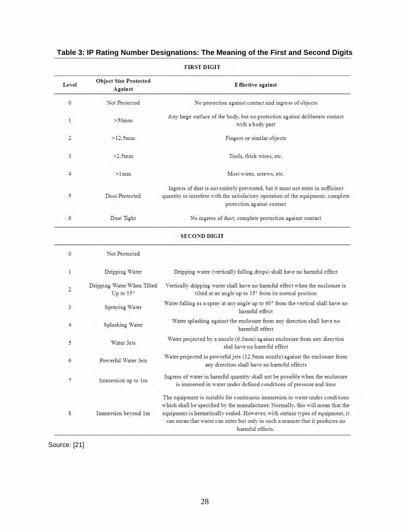
3.2.17 IP Rating
IP rating stands for Ingress Protection Rating. It is a numerical rating system of IP
followed by two digits and one optional letter. As defined in IEC 60529 [20], it classifies the
degrees of protection provided against the intrusion of solid objects including: body parts, dust,
accidental contact, and water in electrical enclosures. The standard aims to provide users more
detailed information than vague marketing terms like “waterproof.”
The digits of IP rating indicate conformity with the conditions summarized in the tables
below. The first digit refers to solids, while the second digit refers to liquids. Table 3 shows the
detailed meaning of the first and second digits. The IP rating of the LED roadway luminaires
should be at least IP65, IP66, and most of them available in the current market are rated IP67.
3.2.18 Life
One of the main selling points of LEDs is their long life. The measurement of LED useful
life is usually determined through lumen depreciation. The life rating is usually demarcated L70,
which is the lifetime of the luminaire based upon the amount of time it takes for the lumens to
depreciate to 70% of the original output. The primary cause of LED lumen depreciation is heat
generated at the LED junction. The typical lifespan of a HPS lamp is on average 20,000 hours.
The service life of LED roadway luminaires available in the current market is ranged from
50,000 hours to 350,000 hours, most of them are in a range of 50,000-100,000 hours. Compared
to the burn out failing mode, the LED light diminishes gradually, as shown in Figure 12. LEDs
prove to be the most cost effective when it comes to lifespan in comparison to all other lamp
types, and technology is continuing to get better and better.
28
Table 3: IP Rating Number Designations: The Meaning of the First and Second Digits
Source: [21]
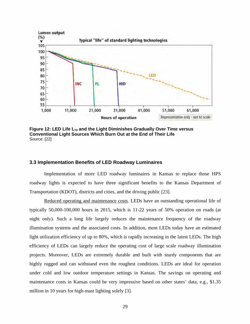
29
Figure 12: LED Life L70 and the Light Diminishes Gradually Over Time versus Conventional Light Sources Which Burn Out at the End of Their Life Source: [22]
3.3 Implementation Benefits of LED Roadway Luminaires
Implementation of more LED roadway luminaires in Kansas to replace those HPS
roadway lights is expected to have three significant benefits to the Kansas Department of
Transportation (KDOT), districts and cities, and the driving public [23].
Reduced operating and maintenance costs. LEDs have an outstanding operational life of
typically 50,000-100,000 hours in 2015, which is 11-22 years of 50% operation on roads (at
night only). Such a long life largely reduces the maintenance frequency of the roadway
illumination systems and the associated costs. In addition, most LEDs today have an estimated
light utilization efficiency of up to 80%, which is rapidly increasing in the latest LEDs. The high
efficiency of LEDs can largely reduce the operating cost of large scale roadway illumination
projects. Moreover, LEDs are extremely durable and built with sturdy components that are
highly rugged and can withstand even the roughest conditions. LEDs are ideal for operation
under cold and low outdoor temperature settings in Kansas. The savings on operating and
maintenance costs in Kansas could be very impressive based on other states’ data, e.g., $1.35
million in 10 years for high-mast lighting solely [3].
30
Safety and efficiency. The LED roadway luminaires have elongated life and reliability in
wide range of operating temperatures and more short-wavelength light in the full light spectrum
to enhance visibility of vehicle operators, which can promote safer and more efficient highway
operations year around than the existing HPS counterparts. They can enhance safety for the
motoring public at night.
Benefits on toxic substances control. All conventional HID lamps on road contain
mercury that is dangerous for the environment. Mercury can be evaporated into the air, deposited
into the soil, and leaked into the water. LED lights are free of toxic chemicals, e.g., mercury and
lead. Replacing HID lamps with LEDs can effectively lower the mercury pollution in the
environment. LED lights are 100% recyclable, and will help Kansas to reduce carbon footprint
by up to a third.
31
Chapter 4: Roadway Lighting Design and Layout
4.1 Review of Roadway Lighting Systems
To guide the roadway lighting design and layout, the AASHTO, FHWA, IES, and CIE
requirements are reviewed for the roadway lighting systems and summarized below.
4.1.1 Classification of Roadway and Pavement
For lighting, the Illuminating Engineering Society (IES) classified the road into the
following categories [24]. Among them, the most interesting ones to Kansas at this moment for
LED lighting and addressed in this manual are bolded and underlined.
Freeway
Expressway
Major
Collector
Local
Alley
Sidewalk
Pedestrian Walkway
Isolated Interchange
Isolated Intersection
Isolated Traffic Conflict Area
Bikeway
In addition, for lighting purpose, IES classified the road pavement into four classes, as
shown in Table 4 [24]. Note that wet roadway conditions are not covered in Table 4. Obtained
from this table is the value Q0, the representative mean luminance coefficient, which is used in
the calculations for this project. Different pavement has different mode of reflectance for lighting
calculations, and thus, different values of Q0. Mostly, an R1 pavement classification with a
corresponding Q0 of 0.1 is a common design value for Kansas LED roadway lighting. Other
values may also be possible.
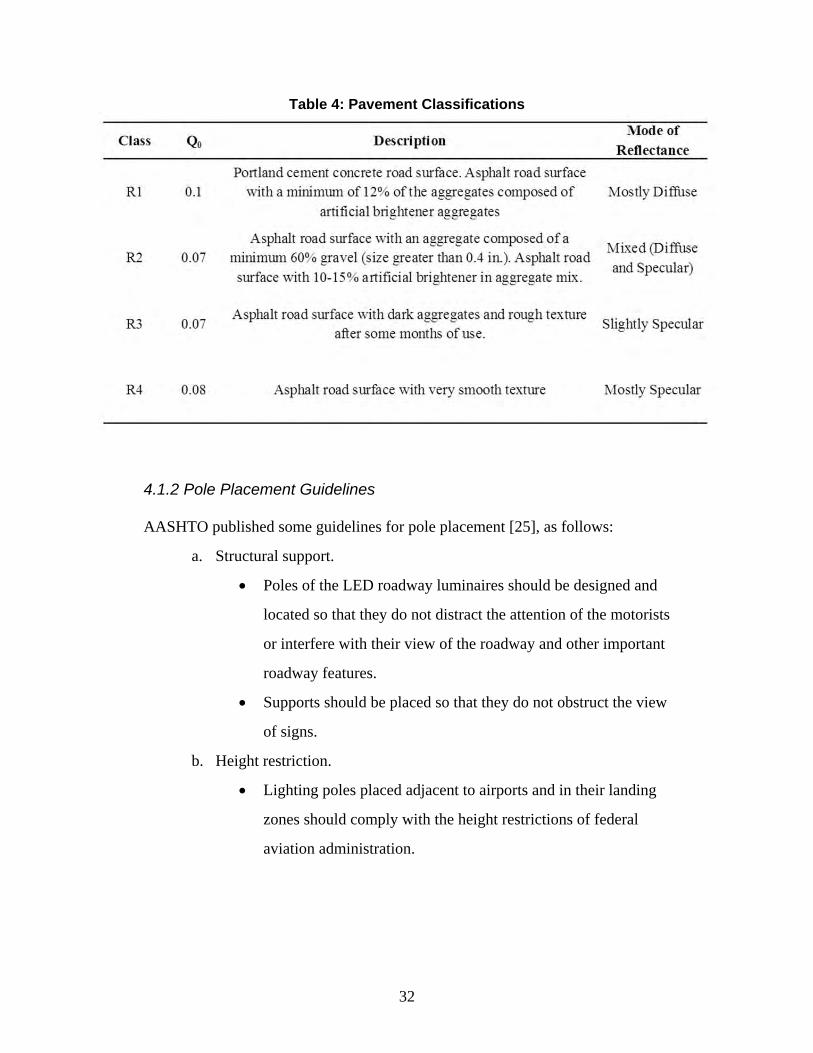
32
Table 4: Pavement Classifications
4.1.2 Pole Placement Guidelines
AASHTO published some guidelines for pole placement [25], as follows:
a. Structural support.
Poles of the LED roadway luminaires should be designed and
located so that they do not distract the attention of the motorists
or interfere with their view of the roadway and other important
roadway features.
Supports should be placed so that they do not obstruct the view
of signs.
b. Height restriction.
Lighting poles placed adjacent to airports and in their landing
zones should comply with the height restrictions of federal
aviation administration.
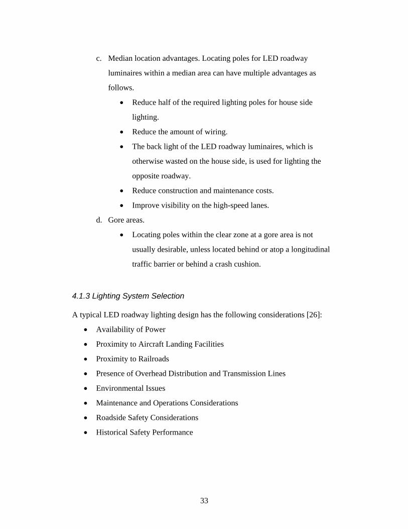
33
c. Median location advantages. Locating poles for LED roadway
luminaires within a median area can have multiple advantages as
follows.
Reduce half of the required lighting poles for house side
lighting.
Reduce the amount of wiring.
The back light of the LED roadway luminaires, which is
otherwise wasted on the house side, is used for lighting the
opposite roadway.
Reduce construction and maintenance costs.
Improve visibility on the high-speed lanes.
d. Gore areas.
Locating poles within the clear zone at a gore area is not
usually desirable, unless located behind or atop a longitudinal
traffic barrier or behind a crash cushion.
4.1.3 Lighting System Selection
A typical LED roadway lighting design has the following considerations [26]:
Availability of Power
Proximity to Aircraft Landing Facilities
Proximity to Railroads
Presence of Overhead Distribution and Transmission Lines
Environmental Issues
Maintenance and Operations Considerations
Roadside Safety Considerations
Historical Safety Performance
34
For selection of the LED roadway luminaires, often the following factors need to be
taken into account [26]:
Quality
Certification
Photometric Performance (for luminaires)
Durability
Aesthetics
Availability
Maintenance Requirements
Operations Cost
In particular, the LED roadway luminaires to be mounted in Kansas, there are some
specific luminaire requirements as follows [26]. Whenever possible, individuals specifying
products are encouraged to designate more than one manufacturer with similar or equal products
to reduce costs via competitive bidding.
Ingress Protection (IP) Rating
Optical systems should be well sealed to prevent the entry of dust
and water. Luminaires should have an IP rating of 65 or 66 for
maximum performance.
Lens Material
Lenses should be composed of glass. Polycarbonate and acrylic
materials, though more impact-resistant, tend to discolor over time,
which will reduce light output and will often require replacement
in about 5 years.
Housing
The housing should be made of aluminum with a powder coat
exterior finish. The luminaire should be designed for secure
attachment to the pole. The luminaire should be designed for easy
access for electrical and lamp changes via a tool-less entry.
35
Internal Electrical
Internal components usually include an LED driver, a photosensor,
and even a temperature sensor.
BUG Ratings
The luminaire optics should meet the specific BUG ratings where
they are available. For standard poles roadside lighting, the best
BUG rating is B0-U0-G0, while the worst BUG rating is B5-U5-
G5. For high-mast lighting, the best BUG rating is probably B3-
U0-G0 for certain amount of backlight without causing glare and
light pollution, while the worst BUG rating is probably B5-U5-G5.
4.1.4 LED Lighting System Layout and Geometry
Typical standard pole spacing layout is shown in Figure 13. These standard pole spacing
layout designations include one-sided lighting, opposite lighting, staggered lighting, and median
lighting [26], as detailed below.
One-sided spacing is typically used on roadways with one to three lanes.
Staggered spacing is typically used on roadways with three to six lanes.
Opposite spacing is typically used on roadways with five or more lanes.
Median lighting is typically used where the median is wide enough to
accommodate poles and meet clear zone requirements, or where the poles
are protected by barriers. From a capital cost perspective, median lighting
may be very cost-effective as the number of poles required may be
reduced by 50% as opposed to opposite lighting. However, median
lighting may cost more to maintain.
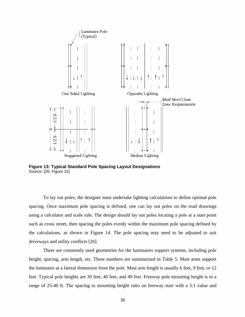
36
Figure 13: Typical Standard Pole Spacing Layout Designations Source: [26, Figure 31]
To lay out poles, the designer must undertake lighting calculations to define optimal pole
spacing. Once maximum pole spacing is defined, one can lay out poles on the road drawings
using a calculator and scale rule. The design should lay out poles locating a pole at a start point
such as cross street, then spacing the poles evenly within the maximum pole spacing defined by
the calculations, as shown in Figure 14. The pole spacing may need to be adjusted to suit
driveways and utility conflicts [26].
There are commonly used geometries for the luminaires support systems, including pole
height, spacing, arm length, etc. These numbers are summarized in Table 5. Mast arms support
the luminaire at a lateral dimension from the pole. Mast arm length is usually 6 feet, 9 feet, or 12
feet. Typical pole heights are 30 feet, 40 feet, and 49 feet. Freeway pole mounting height is in a
range of 25-40 ft. The spacing to mounting height ratio on freeway start with a 5:1 value and
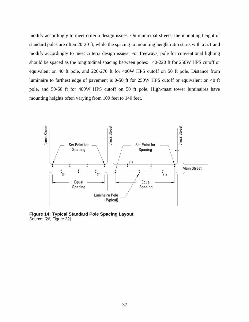
37
modify accordingly to meet criteria design issues. On municipal streets, the mounting height of
standard poles are often 20-30 ft, while the spacing to mounting height ratio starts with a 5:1 and
modify accordingly to meet criteria design issues. For freeways, pole for conventional lighting
should be spaced as the longitudinal spacing between poles: 140-220 ft for 250W HPS cutoff or
equivalent on 40 ft pole, and 220-270 ft for 400W HPS cutoff on 50 ft pole. Distance from
luminaire to farthest edge of pavement is 0-50 ft for 250W HPS cutoff or equivalent on 40 ft
pole, and 50-60 ft for 400W HPS cutoff on 50 ft pole. High-mast tower luminaires have
mounting heights often varying from 100 feet to 140 feet.
Figure 14: Typical Standard Pole Spacing Layout Source: [26, Figure 32]
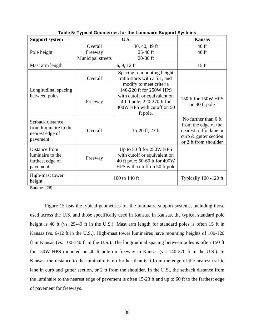
38
Table 5: Typical Geometries for the Luminaire Support Systems Support system U.S. Kansas
Pole height Overall 30, 40, 49 ft 40 ft Freeway 25-40 ft 40 ft
Municipal streets 20-30 ft Mast arm length 6, 9, 12 ft 15 ft
Longitudinal spacing between poles
Overall Spacing to mounting height ratio starts with a 5:1, and
modify to meet criteria
Freeway
140-220 ft for 250W HPS with cutoff or equivalent on
40 ft pole; 220-270 ft for 400W HPS with cutoff on 50
ft pole.
150 ft for 150W HPS on 40 ft pole
Setback distance from luminaire to the nearest edge of pavement
Overall 15-20 ft, 23 ft
No further than 6 ft from the edge of the nearest traffic lane in curb & gutter section or 2 ft from shoulder
Distance from luminaire to the farthest edge of pavement
Freeway
Up to 50 ft for 250W HPS with cutoff or equivalent on 40 ft pole; 50-60 ft for 400W HPS with cutoff on 50 ft pole
High-mast tower height 100 to 140 ft Typically 100 -120 ft
Source: [26]
Figure 15 lists the typical geometries for the luminaire support systems, including those
used across the U.S. and those specifically used in Kansas. In Kansas, the typical standard pole
height is 40 ft (vs. 25-49 ft in the U.S.). Mast arm length for standard poles is often 15 ft in
Kansas (vs. 6-12 ft in the U.S.). High-mast tower luminaires have mounting heights of 100-120
ft in Kansas (vs. 100-140 ft in the U.S.). The longitudinal spacing between poles is often 150 ft
for 150W HPS mounted on 40 ft pole on freeway in Kansas (vs. 140-270 ft in the U.S.). In
Kansas, the distance to the luminaire is no further than 6 ft from the edge of the nearest traffic
lane in curb and gutter section, or 2 ft from the shoulder. In the U.S., the setback distance from
the luminaire to the nearest edge of pavement is often 15-23 ft and up to 60 ft to the farthest edge
of pavement for freeways.
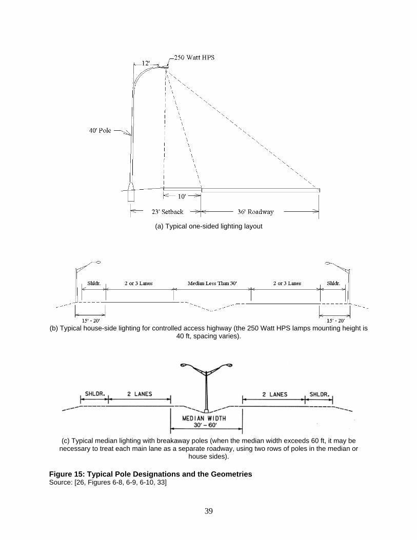
39
(a) Typical one-sided lighting layout
(b) Typical house-side lighting for controlled access highway (the 250 Watt HPS lamps mounting height is
40 ft, spacing varies).
(c) Typical median lighting with breakaway poles (when the median width exceeds 60 ft, it may be
necessary to treat each main lane as a separate roadway, using two rows of poles in the median or house sides).
Figure 15: Typical Pole Designations and the Geometries Source: [26, Figures 6-8, 6-9, 6-10, 33]
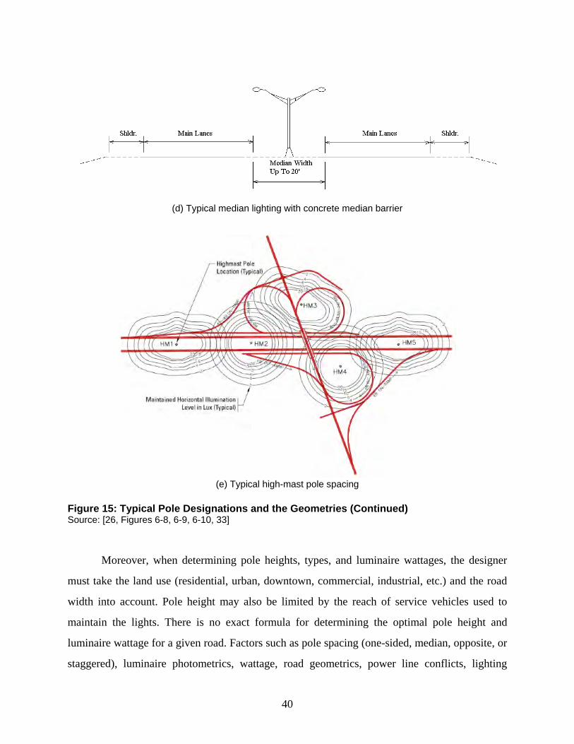
40
(d) Typical median lighting with concrete median barrier
(e) Typical high-mast pole spacing
Figure 15: Typical Pole Designations and the Geometries (Continued) Source: [26, Figures 6-8, 6-9, 6-10, 33]
Moreover, when determining pole heights, types, and luminaire wattages, the designer
must take the land use (residential, urban, downtown, commercial, industrial, etc.) and the road
width into account. Pole height may also be limited by the reach of service vehicles used to
maintain the lights. There is no exact formula for determining the optimal pole height and
luminaire wattage for a given road. Factors such as pole spacing (one-sided, median, opposite, or
staggered), luminaire photometrics, wattage, road geometrics, power line conflicts, lighting
41
levels and uniformity, aesthetics, and obtrusive lighting issues are all appropriate considerations
in defining optimal mounting height. In residential areas, the designer should select pole heights
and fixture wattages to reduce spill light levels to those suitable for the lighting environmental
zones (LZ1-LZ4) [26].
Determination of pole height and luminaire wattage is made using computer lighting
design software, e.g., AGI32, to test different scenarios by a “trial and adjustment” process [26].
For an interchange, high-mast lighting may prove to be more effective than conventional
davit-style, mast-arm, or truss-style lighting. For freeway ramps, intersections or a typical city
roadway, davit-style, mast-arm, or truss-style lighting may prove to be the most effective [26].
4.1.5 Adaptive Lighting Controls
Adaptive lighting controls allow lighting levels to be reduced during off-peak periods.
Considering LED roadway luminaires are superb in dimming controls, a significant amount of
power can be saved by varying the levels of lighting between peak and non-peak periods.
4.2 Lighting Design and Layout
The manual collects all lighting codes, standards, and ordinances for regulating the
proper lighting design and layout for each type of LED roadway lighting systems on the
Approved Products List (APL). As part of this task, technical support from the University of
Kansas lighting research laboratory will also be provided upon request for field lighting
measurements and the assessment of driver’s visual performance, etc.
4.2.1 Roadway Lighting Design Criteria
There are two principal tasks facing the highway lighting specialist when designing an
LED roadway lighting installation. First, there is the choice of overall quality, related to the
function of the road/area to be lit. Second, there is the selection and positioning of the LED
luminaires, and the positioning of the latter above the roadway to give the desired level, spread
and uniformity of luminance. At the same time, the designer has to minimize the amount of glare
from light entering the road user’s eyes directly [27]. There are certain design criteria that the
highway lighting engineer may need to follow, which are summarized as below.
42
4.2.1.1 Standard Pole Lighting
The overall quality of an LED lighting installation is usually evaluated using the
following lighting metrics [24, 25, 27]:
Minimum maintained average illuminance (E) on road pavement
Average luminance Lavg
Maximum allowed illuminance uniformity ratio of Eavg/Emin
Maximum allowed luminance uniformity ratio of Lavg/Lmin
Maximum allowed veiling luminance ratio Lvmax/Lavg
Overall uniformity of luminance, or illuminance, both across and along the
roadway, defined as the minimum divided by the average, and designated
Lmin/Lavg or Emin/Eavg U0.
Uniformity of luminance, or illuminance, along the axis of the road which
coincides with a typical driver’s eye position. Defined as the ratio of the
minimum to the maximum, and designated Lmin/Lmax or Emin/Emax U1.
Glare. As glare has the effect of reducing contrast, a luminaire's "glare
performance," or optical control, can be expressed in terms of the increase
in background luminance necessary to compensate (threshold increment,
TI). The lower the figure the better. In highly motorized countries 10% is
specified for motorways, with 15% and even 30% allowed for general
traffic routes. These percentages are determined by the amount of light the
luminaires project near the horizontal. This light also causes problems of
sky-glow (see later).
For standard roadside pole lighting, the recommended lighting criteria on the pavement
of different types of road are listed in Tables 6 and 7, respectively [24, 25, 27]. Tables 6 and 7
cover the following illumination metrics for different types of road and pavement classification
or different roadway & pedestrian conflict areas, including Minimum maintained average
illuminance (E) on road pavement, Maximum allowed illuminance uniformity ratio of Eavg/Emin,
Maximum allowed veiling luminance ratio Lvmax/Lavg, Average luminance Lavg, Maximum
allowed luminance uniformity ratio of Lavg/Lmin and Lmax/Lmin.
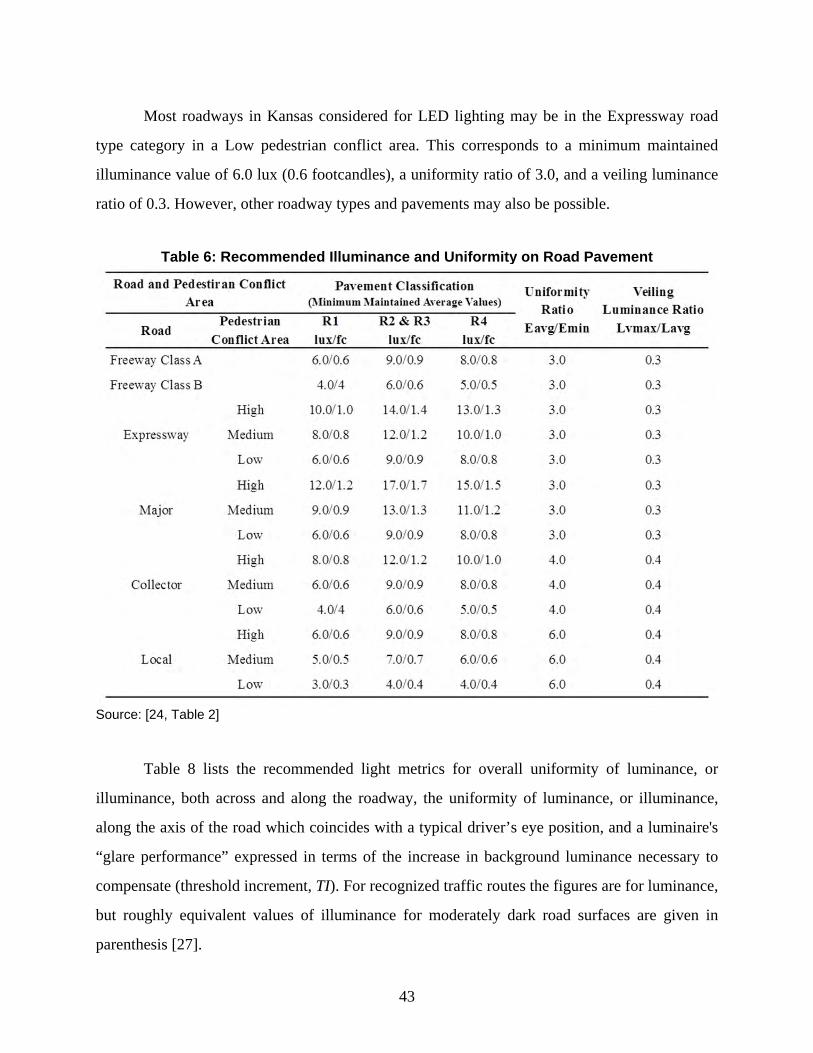
43
Most roadways in Kansas considered for LED lighting may be in the Expressway road
type category in a Low pedestrian conflict area. This corresponds to a minimum maintained
illuminance value of 6.0 lux (0.6 footcandles), a uniformity ratio of 3.0, and a veiling luminance
ratio of 0.3. However, other roadway types and pavements may also be possible.
Table 6: Recommended Illuminance and Uniformity on Road Pavement
Source: [24, Table 2]
Table 8 lists the recommended light metrics for overall uniformity of luminance, or
illuminance, both across and along the roadway, the uniformity of luminance, or illuminance,
along the axis of the road which coincides with a typical driver’s eye position, and a luminaire's
“glare performance” expressed in terms of the increase in background luminance necessary to
compensate (threshold increment, TI). For recognized traffic routes the figures are for luminance,
but roughly equivalent values of illuminance for moderately dark road surfaces are given in
parenthesis [27].
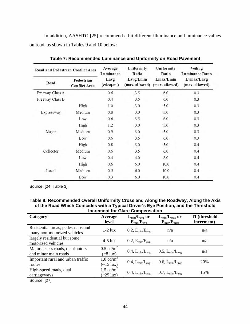
44
In addition, AASHTO [25] recommend a bit different illuminance and luminance values
on road, as shown in Tables 9 and 10 below:
Table 7: Recommended Luminance and Uniformity on Road Pavement
Source: [24, Table 3]
Table 8: Recommended Overall Uniformity Cross and Along the Roadway, Along the Axis
of the Road Which Coincides with a Typical Driver’s Eye Position, and the Threshold Increment for Glare Compensation
Category Average level
Lmin/Lavg or Emin/Eavg
Lmin/Lmax or Emin/Emax
TI (threshold increment)
Residential areas, pedestrians and many non-motorized vehicles 1-2 lux 0.2, Emin/Eavg n/a n/a
largely residential but some motorized vehicles 4-5 lux 0.2, Emin/Eavg n/a n/a
Major access roads, distributors and minor main roads
0.5 cd/m2 (~8 lux) 0.4, Lmin/Lavg 0.5, Lmin/Lavg n/a
Important rural and urban traffic routes
1.0 cd/m2 (~15 lux) 0.4, Lmin/Lavg 0.6, Lmin/Lavg 20%
High-speed roads, dual carriageways
1.5 cd/m2 (~25 lux) 0.4, Lmin/Lavg 0.7, Lmin/Lavg 15%
Source: [27]
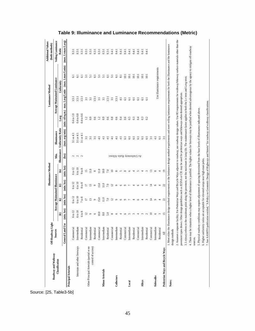
45
Table 9: Illuminance and Luminance Recommendations (Metric)
Source: [25, Table3-5b]
Addi
tiona
l Val
ues
(bot
h m
etho
ds)
R1R2
R3R4
Lavg
Gen
eral
Lan
d U
se(m
in. l
ux)
(min
. lux
)(m
in. l
ux)
(min
. lux
)(lu
x)(m
ax. a
vg/m
in)
(min
. cd/
sq.m
.)m
ax. L
avg/
Lmin
(max
. Lm
ax/L
min
)(m
ax. L
vmax
/Lav
g)Pr
inci
pal A
rter
ials
Com
mer
cial
6 to
12
6 to
12
6 to
12
6 to
12
23:
1 or
4:1
0.4
to 1
.03.
5:1
6:1
0.3:
1In
term
edia
te6
to 1
06
to 1
06
to 1
06
to 1
02
3:1
or 4
:10.
4 to
0.8
3.5:
16:
10.
3:1
Resid
entia
l6
to 8
7 to
88
to 8
9 to
82
3:1
or 4
:10.
4 to
0.6
3.5:
16:
10.
3:1
Com
mer
cial
1217
1715
3:1
1.2
3:1
5:1
0.3:
1In
term
edia
te9
1313
11.0
3:1
0.9
3:1
5:1
0.3:
1Re
siden
tial
69
98
3:1
0.6
3.5:
16:
10.
3:1
Com
mer
cial
10.0
15.0
15.0
11.0
4:1
1.2
3:1
5:1
0.3:
1In
term
edia
te8.
011
.011
.010
.04:
10.
93:
15:
10.
3:1
Resid
entia
l5.
07.
07.
07.
04:
10.
63.
5:1
6:1
0.3:
1Co
mm
erci
al8
1212
104:
10.
83:
15:
10.
4:1
Inte
rmed
iate
69
98
4:1
0.6
3.5:
16:
10.
4:1
Resid
entia
l4
66
54:
10.
44:
18:
10.
4:1
Com
mer
cial
69
98
6:1
0.6
6:1
10:1
0.4:
1In
term
edia
te5
77
66:
10.
56:
110
:10.
4:1
Resid
entia
l3
44
46:
10.
36:
110
:10.
4:1
Com
mer
cial
46
65
6:1
0.4
6:1
10:1
0.4:
1In
term
edia
te3
44
46:
10.
36:
110
:10.
4:1
Resid
entia
l2
33
36:
10.
26:
110
:10.
4:1
Com
mer
cial
1014
1413
3:1
Inte
rmed
iate
69
98
4:1
Resid
entia
l3
44
46:
1Pe
destr
ian
Way
s and
Bic
ycle
Way
sAl
l15
2222
193:
1
Note
s:
6. H
ighe
r uni
form
ity ra
tios a
re ac
cept
able
for e
levat
ed ra
mps
nea
r hig
h-m
ast p
oles
.7.
See
AAS
HTO
pub
licat
ion
entit
led, "
A Po
licy
on G
eom
etric
Des
ign
of H
ighw
ays a
nd S
treet
s" fo
r roa
dway
and
walk
way
clas
sific
ation
s.
Use i
llum
inan
ce re
quire
men
ts
1. M
eet e
ither
the i
llum
inan
ce d
esig
n m
ethod
requ
irem
ents
or th
e lum
inan
ce d
esig
n m
ethod
requ
irem
ents
and
mee
t vei
ling
lum
inan
ce re
quire
men
ts fo
r bot
h th
e illu
min
ance
and
the l
umin
ance
de
sign
meth
ods
2. A
ssum
es a
sepa
rate
faci
lity.
For P
edes
trian
Way
s and
Bic
ycle
Way
s adj
acen
t to
road
way
, use
road
way
des
ign
valu
es. U
se R
3 re
quire
men
ts fo
r walk
way
/bik
eway
surfa
ce m
ater
ials
othe
r tha
n th
e pa
vem
ent t
ypes
show
n. O
ther
des
ign
guid
elin
es su
ch as
IESN
A or
CIE
may
be
used
for p
edes
trian
way
s and
bik
eway
s whe
n de
emed
appr
opria
te.
3. L
v(m
ax) r
efer
es to
the m
axim
um p
oint
alon
g th
e pav
emen
t, no
t the
max
imum
in la
mp
life.
The m
aint
enan
ce fa
ctor a
pplie
s to
both
the L
v te
rm an
d La
vg te
rm.
4. T
here
may
be s
ituat
ions
whe
n a h
ighe
r lev
el o
f illu
min
ance
is ju
stifie
d. T
he h
ighe
r val
ues f
or fr
eew
ays m
ay b
e jus
tifie
d w
hen
deem
ed ad
vant
ageo
us b
y th
e age
ncy
to m
itiga
te o
ff-ro
adw
ay
sour
ces.
5. P
hysic
al ro
adw
ay co
nditi
ons m
ay re
quire
adju
stmen
t of s
paci
ng d
eter
min
ed fr
om th
e bas
e lev
els o
f illu
min
ance
indi
cate
d ab
ove.
Veili
ng L
umin
ance
Ra
tioUn
iform
ity
Inte
rsta
te an
d ot
her f
reew
ays
Othe
r Prin
cipa
l Arte
rials
(par
tial o
r no
cont
rol o
f acc
ess)
As Uniformity Ratio Allows
Min
or A
rter
ials
Colle
ctor
s
Loca
l
Alley
s
Side
wal
ksRoad
way
and
Wal
kway
Cl
assif
icat
ion
Off-
Roa
dway
Lig
ht
Sour
ces
Illum
inan
ce M
etho
dLu
min
ance
Met
hod
Aver
age M
aint
aine
d Ill
umin
nace
Min
. Ill
umin
ance
Illum
inan
ce
Unifo
rmity
Rat
ioAv
erag
e Mai
ntai
ned
Lum
inan
ce
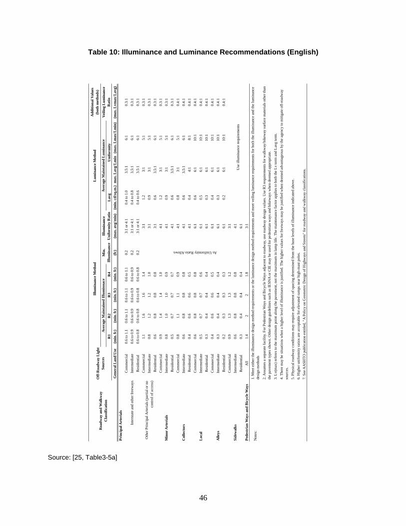
46
Table 10: Illuminance and Luminance Recommendations (English) Source: [25, Table3-5a]
Add
ition
al V
alue
s (b
oth
met
hods
)
R1
R2
R3
R4
Lav
gG
ener
al L
and
Use
(min
. fc)
(min
. fc)
(min
. fc)
(min
. fc)
(fc)
(max
. avg
/min
)(m
in. c
d/sq
.m.)
max
. Lav
g/L
min
(max
. Lm
ax/L
min
)(m
ax. L
vmax
/Lav
g)Pr
inci
pal A
rter
ials
Com
mer
cial
0.6
to 1
.10.
6 to
1.1
0.6
to 1
.10.
6 to
1.1
0.2
3:1
or 4
:10.
4 to
1.0
3.5:
16:
10.
3:1
Inte
rmed
iate
0.6
to 0
.90.
6 to
0.9
0.6
to 0
.90.
6 to
0.9
0.2
3:1
or 4
:10.
4 to
0.8
3.5:
16:
10.
3:1
Res
iden
tial
0.6
to 0
.80.
6 to
0.8
0.6
to 0
.80.
6 to
0.8
0.2
3:1
or 4
:10.
4 to
0.6
3.5:
16:
10.
3:1
Com
mer
cial
1.1
1.6
1.6
1.4
3:1
1.2
3:1
5:1
0.3:
1In
term
edia
te0.
81.
21.
21.
03:
10.
93:
15:
10.
3:1
Res
iden
tial
0.6
0.8
0.8
0.8
3:1
0.6
3.5:
16:
10.
3:1
Com
mer
cial
0.9
1.4
1.4
1.0
4:1
1.2
3:1
5:1
0.3:
1In
term
edia
te0.
81.
01.
00.
94:
10.
93:
15:
10.
3:1
Res
iden
tial
0.5
0.7
0.7
0.7
4:1
0.6
3.5:
16:
10.
3:1
Com
mer
cial
0.8
1.1
1.1
0.9
4:1
0.8
3:1
5:1
0.4:
1In
term
edia
te0.
60.
80.
80.
84:
10.
63.
5:1
6:1
0.4:
1R
esid
entia
l0.
40.
60.
60.
54:
10.
44:
18:
10.
4:1
Com
mer
cial
0.6
0.8
0.8
0.8
6:1
0.6
6:1
10:1
0.4:
1In
term
edia
te0.
50.
70.
70.
66:
10.
56:
110
:10.
4:1
Res
iden
tial
0.3
0.4
0.4
0.4
6:1
0.3
6:1
10:1
0.4:
1C
omm
erci
al0.
40.
60.
60.
56:
10.
46:
110
:10.
4:1
Inte
rmed
iate
0.3
0.4
0.4
0.4
6:1
0.3
6:1
10:1
0.4:
1R
esid
entia
l0.
20.
30.
30.
36:
10.
26:
110
:10.
4:1
Com
mer
cial
0.9
1.3
1.3
1.2
3:1
Inte
rmed
iate
0.6
0.8
0.8
0.8
4:1
Res
iden
tial
0.3
0.4
0.4
0.4
6:1
Pede
stri
an W
ays a
nd B
icyc
le W
ays
All
1.4
22
1.8
3:1
Not
es:
7. S
ee A
ASH
TO p
ublic
atio
n en
title
d, "
A P
olic
y on
Geo
met
ric D
esig
n of
Hig
hway
s and
Stre
ets"
for r
oadw
ay a
nd w
alkw
ay c
lass
ifica
tions
.
1. M
eet e
ither
the
illum
inan
ce d
esig
n m
etho
d re
quire
men
ts o
r the
lum
inan
ce d
esig
n m
etho
d re
quire
men
ts a
nd m
eet v
eilin
g lu
min
ance
requ
irem
ents
for b
oth
the
illum
inan
ce a
nd th
e lu
min
ance
de
sign
met
hods
2. A
ssum
es a
sepa
rate
faci
lity.
For
Ped
estri
an W
ays a
nd B
icyc
le W
ays a
djac
ent t
o ro
adw
ay, u
se ro
adw
ay d
esig
n va
lues
. Use
R3
requ
irem
ents
for w
alkw
ay/b
ikew
ay su
rface
mat
eria
ls o
ther
than
th
e pa
vem
ent t
ypes
show
n. O
ther
des
ign
guid
elin
es su
ch a
s IES
NA
or C
IE m
ay b
e us
ed fo
r ped
estri
an w
ays a
nd b
ikew
ays w
hen
deem
ed a
ppro
pria
te.
3. L
v(m
ax) r
efer
es to
the
max
imum
poi
nt a
long
the
pave
men
t, no
t the
max
imum
in la
mp
life.
The
mai
nten
ance
fact
or a
pplie
s to
both
the
Lv te
rm a
nd L
avg
term
.4.
The
re m
ay b
e si
tuat
ions
whe
n a
high
er le
vel o
f illu
min
ance
is ju
stifi
ed. T
he h
ighe
r val
ues f
or fr
eew
ays m
ay b
e ju
stifi
ed w
hen
deem
ed a
dvan
tage
ous b
y th
e ag
ency
to m
itiga
te o
ff-ro
adw
ay
sour
ces.
5. P
hysi
cal r
oadw
ay c
ondi
tions
may
requ
ire a
djus
tmen
t of s
paci
ng d
eter
min
ed fr
om th
e ba
se le
vels
of i
llum
inan
ce in
dica
ted
abov
e.6.
Hig
her u
nifo
rmity
ratio
s are
acc
epta
ble
for e
leva
ted
ram
ps n
ear h
igh-
mas
t pol
es.
Min
or A
rter
ials
Col
lect
ors
Loc
al
Alle
ys
Side
wal
ksU
se il
lum
inan
ce re
quire
men
ts
As Uniformity Ratio Allows
Lum
inan
ce M
etho
d
Aver
age
Mai
ntai
ned
Lum
inan
ceU
nifo
rmity
Veili
ng L
umin
ance
R
atio
Inte
rsta
te a
nd o
ther
free
way
s
Oth
er P
rinci
pal A
rteria
ls (p
artia
l or n
o co
ntro
l of a
cces
s)
Aver
age
Mai
ntai
ned
Illu
min
nace
Illu
min
ance
Met
hod
Min
. Il
lum
inan
ceIl
lum
inan
ce
Uni
form
ity R
atio
Off-
Roa
dway
Lig
ht
Sour
ces
Roa
dway
and
Wal
kway
C
lass
ifica
tion
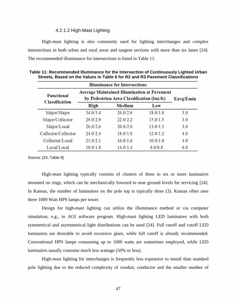
47
4.2.1.2 High-Mast Lighting
High-mast lighting is also commonly used for lighting interchanges and complex
intersections in both urban and rural areas and tangent sections with more than six lanes [24].
The recommended illuminance for intersections is listed in Table 11.
Table 11: Recommended Illuminance for the Intersection of Continuously Lighted Urban
Streets, Based on the Values in Table 6 for R2 and R3 Pavement Classifications
Source: [24, Table 9]
High-mast lighting typically consists of clusters of three to six or more luminaires
mounted on rings, which can be mechanically lowered to near ground levels for servicing [24].
In Kansas, the number of luminaires on the pole top is typically three (3). Kansas often uses
three 1000 Watt HPS lamps per tower.
Design for high-mast lighting can utilize the illuminance method or via computer
simulation, e.g., in AGI software program. High-mast lighting LED luminaires with both
symmetrical and asymmetrical light distributions can be used [24]. Full cutoff and cutoff LED
luminaires are desirable to avoid excessive glare, while full cutoff is already recommended.
Conventional HPS lamps consuming up to 1000 watts are sometimes employed, while LED
luminaires usually consume much less wattage (50% or less).
High-mast lighting for interchanges is frequently less expensive to install than standard
pole lighting due to the reduced complexity of conduit, conductor and the smaller number of
48
luminaires and poles required [24]. Note that other than these interchange locations, conventional
standard pole lighting usually requires a smaller initial cost.
4.2.1.3 Spill Light Level
Spill light level criteria are developed and documented by the IES [28, 29]. Classification
factors that will be listed on the warrant sheets of the LED lighting installation are defined as
follows [26]:
Number of lanes
Lane width
Number of median openings per mile
Driveways and entrances per mile
Horizontal curve radius
Vertical grade
Sight distance
Parking
Based on these factors, different lighting zones are defined for light trespass classification
as listed below.
LZ1 Zone - Dark Ambient Lighting (e.g., state parks, recreation areas, and
wildlife preserves)
LZ2 Zone - Low Ambient Lighting (e.g., rural areas, as defined by the
2000 U.S. Census)
LZ3 Zone - Medium Ambient Lighting (e.g., urban areas, as defined by
the 2000 U.S. Census)
LZ4 Zone - High Ambient Lighting (e.g., metropolitan areas)
In the designated Lighting Zone (LZ1 to LZ4), the design values for spill light levels are
shown in Table 12. These levels are recommended by the IES where possible. They are typically
calculated and measured from the residential boundary line, but are sometimes evaluated from
the location of the residence being investigated [26]. Since most of Kansas is rural, most LED
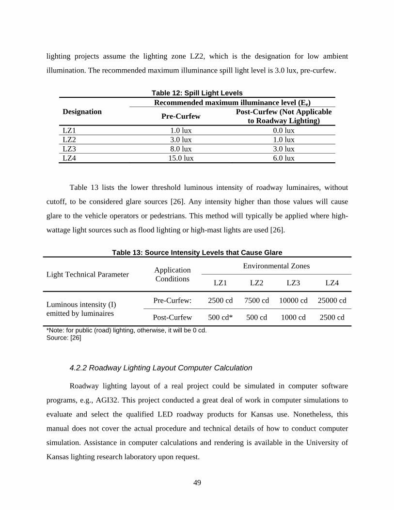
49
lighting projects assume the lighting zone LZ2, which is the designation for low ambient
illumination. The recommended maximum illuminance spill light level is 3.0 lux, pre-curfew.
Table 12: Spill Light Levels
Designation Recommended maximum illuminance level (Ee)
Pre-Curfew Post-Curfew (Not Applicable to Roadway Lighting)
LZ1 1.0 lux 0.0 lux LZ2 3.0 lux 1.0 lux LZ3 8.0 lux 3.0 lux LZ4 15.0 lux 6.0 lux
Table 13 lists the lower threshold luminous intensity of roadway luminaires, without
cutoff, to be considered glare sources [26]. Any intensity higher than those values will cause
glare to the vehicle operators or pedestrians. This method will typically be applied where high-
wattage light sources such as flood lighting or high-mast lights are used [26].
Table 13: Source Intensity Levels that Cause Glare
Light Technical Parameter Application Conditions
Environmental Zones
LZ1 LZ2 LZ3 LZ4
Luminous intensity (I) emitted by luminaires
Pre-Curfew: 2500 cd 7500 cd 10000 cd 25000 cd
Post-Curfew 500 cd* 500 cd 1000 cd 2500 cd *Note: for public (road) lighting, otherwise, it will be 0 cd. Source: [26]
4.2.2 Roadway Lighting Layout Computer Calculation
Roadway lighting layout of a real project could be simulated in computer software
programs, e.g., AGI32. This project conducted a great deal of work in computer simulations to
evaluate and select the qualified LED roadway products for Kansas use. Nonetheless, this
manual does not cover the actual procedure and technical details of how to conduct computer
simulation. Assistance in computer calculations and rendering is available in the University of
Kansas lighting research laboratory upon request.
50
In AGi32, the calculation grid is often set at 3 x 3 feet across the road surfaces.
Calculation results include the horizontal illuminance, vertical illuminance, spill light levels, and
driver’s eye luminance. The horizontal calculation points are located on the pavement, while the
vertical calculation points are placed 5 feet above the pavement. The spill light levels are
calculated in the single row of calculation points surrounding the roadway. The driver’s eye
luminance levels are calculated in the vertical calculation points at both the top and bottom of the
roadway.
For all of the luminaire simulations completed in AGi32, a simulation report can be
compiled in order to summarize the performance of the luminaire. For standard pole lighting,
each report includes a page summarizing 1) the luminaire properties, 2) the one-sided lighting
calculation results, 3) the staggered lighting calculation results, 4) the opposite lighting
calculation results, and 5) the median lighting calculation results. For high-mast lighting, the
report could cover lighting performance evaluation for highway interchanges or major
intersections.
51
Chapter 5: Selection of Qualified LED Roadway Luminaires
5.1 Specifications of Qualified LED Roadway Lighting Systems
5.1.1 List of Factors for Specifications
The specifications of qualified LED roadway lighting products, poles, and supporting
electrical systems should at least comply with the requirements of AASHTO (American
Association of State Highway and Transportation Officials), FHWA (Federal Highway
Administration), IES (Illuminating Engineering Society), and CIE (International Commission On
Illumination) standards, and also comply with state and local specifications.
A complete list of specifications of qualified LED roadway lighting systems may include
the following:
Manufacturer
Luminaire model #
Voltage (DC/AC)
Drive current (mA)
Wattage
Luminaire dimensions (L x W x H) / Length & Height
Luminaire weight
Lens (glass)
Mount style (post-top, side-arm, etc.)
Pole height (if post-top mounted)
Pole spacing (vary with different layout)
Arm length, horizontal (not including luminaire length unless specified)
Luminaires per pole
Number of LEDs per luminaire
Initial lumen
Uniformity (on the pavement)
Efficacy (Lumen/Watt)
CCT (K)
52
CRI
Light lateral distribution (Type I - V)
Cutoff classification (full cutoff, cutoff, semi-cutoff, non-cutoff)
BUG rating
LED driver manufacturer
Driver model #
Control technology (passive infrared, Ultrasonic, or dual tech, etc.)
Dimming or non-dimming
Light curfews
Sensor types (daylight photosensor, occupancy, etc.)
Sensor mount location
Coverage pattern (circle 360 degree, rectangular, etc.)
Luminaire certificate (UL, CSA, ETL, etc.)
Luminaire IP rating
Luminaire life L70
Costs
Warranty
In addition, a list of specifications of the roadway environment may include the
following:
Surrounding land use
Surrounding lighting
Traffic flow
Traffic management interaction
Safety and security concerns
Sky glow and light trespass issues, etc.
53
While all those factors are important for the specifications of qualified LED roadway
lighting systems in certain road environments, there are some key factors that are frequently used
in roadway lighting design and layout. Those key factors are listed below.
Initial lumen
Uniformity (on the pavement)
Efficacy (Lumen/Watt)
CCT (K)
CRI
Light lateral distribution (Type I - V)
Cutoff classification (full cutoff, cutoff, semi-cutoff, non-cutoff)
BUG rating
Control technology (passive infrared, Ultrasonic, or dual tech. etc.)
Dimming or non-dimming
Luminaire certificate (UL, CSA, ETL, etc.)
Luminaire IP rating
Luminaire life L70
Costs
Warranty
5.1.2 Recommended Specifications for Qualified LED Roadway Luminaires
During the design stage of LED lighting, designers need to determine the minimum
required value of the most essential property of each roadway luminaire to comply with the
recommended levels by codes and standards (aforementioned). While all those factors listed in
Table 1 before are important for the specifications of qualified LED roadway lighting systems in
certain road environments, there are several key factors that are most frequently used in roadway
lighting design and layout, including initial lumen output, luminaire efficacy, CCT, CRI, light
lateral distribution, cutoff, light levels on the pavement and the uniformity, lighting zone, spill
light, BUG rating, control technology, dimming, certificate, IP rating, life, cost, and warranty.
54
The specifications of qualified LED roadway lighting products, poles, and supporting
electrical systems should comply with the requirements of AASHTO (American Association of
State Highway and Transportation Officials) [25], FHWA (Federal Highway Administration)
[26], IES (Illuminating Engineering Society) [28-32], CIE (International Commission On
Illumination) [33] standards, and also comply with Kansas state [34] and local city specifications
if any.
A pilot run of the computer simulation tests of sample products in more than 140 product
families was also conducted. In the pilot run of computer simulations, a standard luminaire
layout was tested for each roadway type (one-sided, staggered, opposite, median) based off of
the most respected codes and standards. The luminaire layout is as follows:
Luminaire Spacing: 60 feet
Mounting Height: 40 feet
Arm Length: 15 feet
Luminaire Offset: 5 feet from roadway shoulder
It was determined in the pilot run that a minimum lumen output of about 4000 lumen (at
least 3700 lm, ideally 4000 or more lm) is required to satisfy the horizontal illuminance required
of 0.6 footcandles but with fluctuations depending on the luminaire design and distribution
pattern. The minimum luminaire efficacy is recommended as ≥ 60 lm/W. Also, light lateral
distribution should be types III, IV, V, and VS. Types I and II are tested inappropriate for typical
highway lighting.
Based on a thorough review of those requirements and results of the pilot run of the
computer simulation tests, the key specifications of qualified products were identified. Table 14
lists the values required for qualified LED roadway lighting products on the Approved Products
List (APL) for roadways in Kansas. Table 15 is the recommended specifications for qualified
LED roadway luminaires.
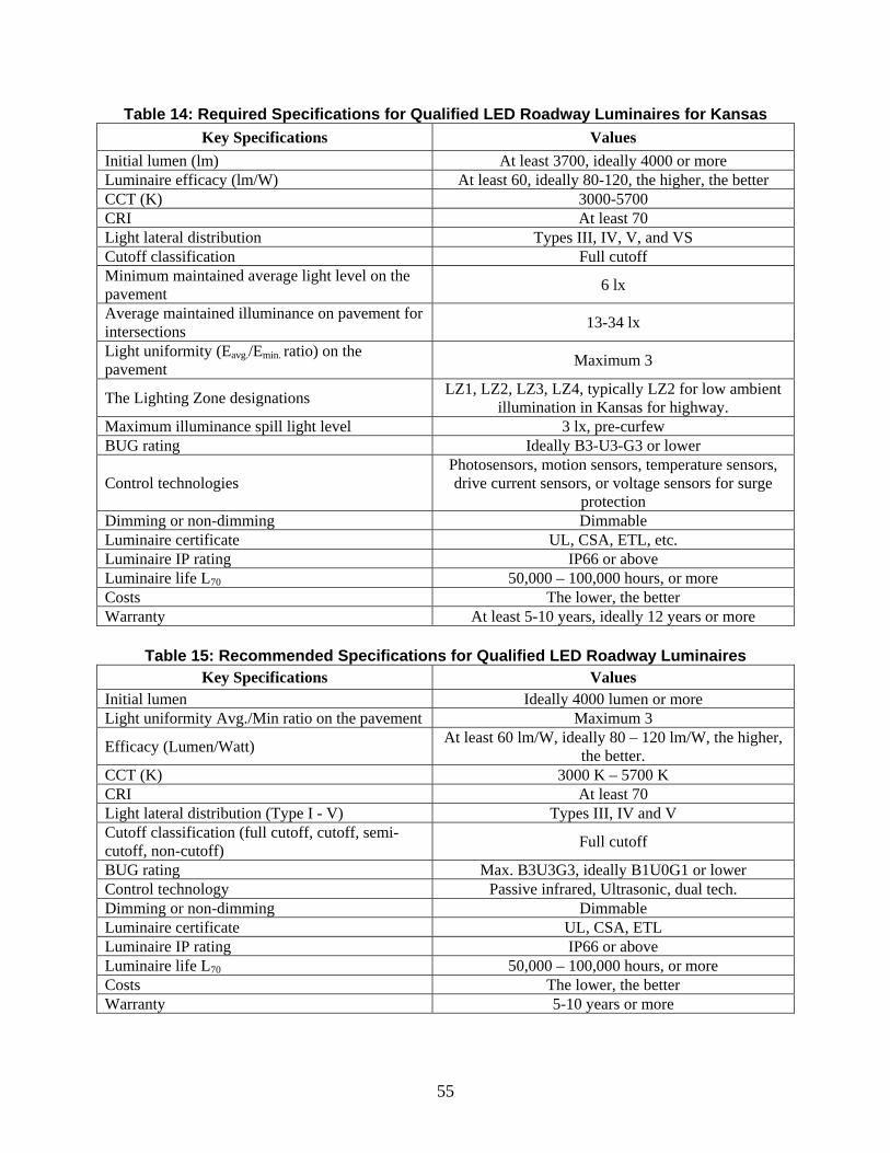
55
Table 14: Required Specifications for Qualified LED Roadway Luminaires for Kansas Key Specifications Values
Initial lumen (lm) At least 3700, ideally 4000 or more Luminaire efficacy (lm/W) At least 60, ideally 80-120, the higher, the better CCT (K) 3000-5700 CRI At least 70 Light lateral distribution Types III, IV, V, and VS Cutoff classification Full cutoff Minimum maintained average light level on the pavement 6 lx
Average maintained illuminance on pavement for intersections 13-34 lx
Light uniformity (Eavg./Emin. ratio) on the pavement Maximum 3
The Lighting Zone designations LZ1, LZ2, LZ3, LZ4, typically LZ2 for low ambient illumination in Kansas for highway.
Maximum illuminance spill light level 3 lx, pre-curfew BUG rating Ideally B3-U3-G3 or lower
Control technologies Photosensors, motion sensors, temperature sensors, drive current sensors, or voltage sensors for surge
protection Dimming or non-dimming Dimmable Luminaire certificate UL, CSA, ETL, etc. Luminaire IP rating IP66 or above Luminaire life L70 50,000 – 100,000 hours, or more Costs The lower, the better Warranty At least 5-10 years, ideally 12 years or more
Table 15: Recommended Specifications for Qualified LED Roadway Luminaires
Key Specifications Values Initial lumen Ideally 4000 lumen or more Light uniformity Avg./Min ratio on the pavement Maximum 3
Efficacy (Lumen/Watt) At least 60 lm/W, ideally 80 – 120 lm/W, the higher, the better.
CCT (K) 3000 K – 5700 K CRI At least 70 Light lateral distribution (Type I - V) Types III, IV and V Cutoff classification (full cutoff, cutoff, semi-cutoff, non-cutoff) Full cutoff
BUG rating Max. B3U3G3, ideally B1U0G1 or lower Control technology Passive infrared, Ultrasonic, dual tech. Dimming or non-dimming Dimmable Luminaire certificate UL, CSA, ETL Luminaire IP rating IP66 or above Luminaire life L70 50,000 – 100,000 hours, or more Costs The lower, the better Warranty 5-10 years or more
56
5.2 Prequalified Product List (PQL)
The compilation of the Prequalified Product List (PQL) was the first task completed in
the project. Many manufacturers make LED roadway lighting systems, including luminaires and
controls, whose specification details are often available online. The research team conducted a
comprehensive search of all LED roadway luminaires available in the current U.S. market. In
addition, the manufacturer’s sales representatives, with their best technologies on the market,
aided the project team in gaining the most recent information of the LED roadway luminaires.
Through compiling product specification sheets and communications with sales representatives,
the PQL was made. As seen in Appendix A, the PQL contains a total of 146 LED roadway
luminaires from various manufacturers in the United States and Canada.
Nonetheless, the 146 LED roadway luminaires on the PQL are too many for practical
implementation. They were evaluated based on the information provided by the manufacturers,
thus, their photometric performance need to be tested in this project for roadway uses in Kansas.
The project team conducted the second task—the acceptance testing—to test all products on the
PQL to find the qualified LED luminaires that are most appropriate for roadway lighting in
Kansas.
5.3 Acceptance Testing in AGi32
All of the 146 LED luminaires on the Prequalified Product List (PQL), each with various
models, were screened over the key specifications listed in Table 2. Their photometric
performance was tested via computer simulation in the AGi32 software for optimized roadway
layout and luminaire placement. Luminaire photometric performance analyses include
calculating horizontal illuminance and uniformity on the pavement, vertical illuminance, and
spill light levels. The test results were compared to the key specifications summarized in Table 2
for judgment of their compliance with the codes and standards. Additionally, AGi32 was used
for visualization of the lighting systems to predict the roadway lighting effect in real world.
In the AGi32 simulation, ideally every single model (with its individual IES file) of the
146 LED luminaires should be tested on typical roadway layouts in Kansas. Such testing
configurations include typical roadway types, typical pole spacing, and typical geometries of the
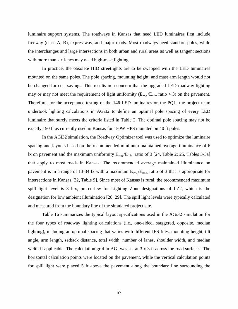
57
luminaire support systems. The roadways in Kansas that need LED luminaires first include
freeway (class A, B), expressway, and major roads. Most roadways need standard poles, while
the interchanges and large intersections in both urban and rural areas as well as tangent sections
with more than six lanes may need high-mast lighting.
In practice, the obsolete HID streetlights are to be swapped with the LED luminaires
mounted on the same poles. The pole spacing, mounting height, and mast arm length would not
be changed for cost savings. This results in a concern that the upgraded LED roadway lighting
may or may not meet the requirement of light uniformity (Eavg./Emin. ratio ≤ 3) on the pavement.
Therefore, for the acceptance testing of the 146 LED luminaires on the PQL, the project team
undertook lighting calculations in AGi32 to define an optimal pole spacing of every LED
luminaire that surely meets the criteria listed in Table 2. The optimal pole spacing may not be
exactly 150 ft as currently used in Kansas for 150W HPS mounted on 40 ft poles.
In the AGi32 simulation, the Roadway Optimizer tool was used to optimize the luminaire
spacing and layouts based on the recommended minimum maintained average illuminance of 6
lx on pavement and the maximum uniformity Eavg./Emin. ratio of 3 [24, Table 2; 25, Tables 3-5a]
that apply to most roads in Kansas. The recommended average maintained illuminance on
pavement is in a range of 13-34 lx with a maximum Eavg./Emin. ratio of 3 that is appropriate for
intersections in Kansas [32, Table 9]. Since most of Kansas is rural, the recommended maximum
spill light level is 3 lux, pre-curfew for Lighting Zone designations of LZ2, which is the
designation for low ambient illumination [28, 29]. The spill light levels were typically calculated
and measured from the boundary line of the simulated project site.
Table 16 summarizes the typical layout specifications used in the AGi32 simulation for
the four types of roadway lighting calculations (i.e., one-sided, staggered, opposite, median
lighting), including an optimal spacing that varies with different IES files, mounting height, tilt
angle, arm length, setback distance, total width, number of lanes, shoulder width, and median
width if applicable. The calculation grid in AGi was set at 3 x 3 ft across the road surfaces. The
horizontal calculation points were located on the pavement, while the vertical calculation points
for spill light were placed 5 ft above the pavement along the boundary line surrounding the
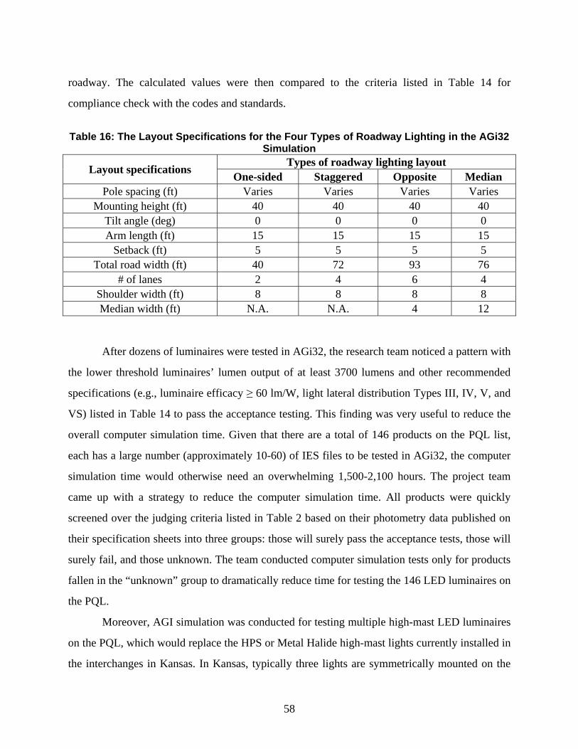
58
roadway. The calculated values were then compared to the criteria listed in Table 14 for
compliance check with the codes and standards.
Table 16: The Layout Specifications for the Four Types of Roadway Lighting in the AGi32
Simulation
Layout specifications Types of roadway lighting layout One-sided Staggered Opposite Median
Pole spacing (ft) Varies Varies Varies Varies Mounting height (ft) 40 40 40 40
Tilt angle (deg) 0 0 0 0 Arm length (ft) 15 15 15 15
Setback (ft) 5 5 5 5 Total road width (ft) 40 72 93 76
# of lanes 2 4 6 4 Shoulder width (ft) 8 8 8 8 Median width (ft) N.A. N.A. 4 12
After dozens of luminaires were tested in AGi32, the research team noticed a pattern with
the lower threshold luminaires’ lumen output of at least 3700 lumens and other recommended
specifications (e.g., luminaire efficacy ≥ 60 lm/W, light lateral distribution Types III, IV, V, and
VS) listed in Table 14 to pass the acceptance testing. This finding was very useful to reduce the
overall computer simulation time. Given that there are a total of 146 products on the PQL list,
each has a large number (approximately 10-60) of IES files to be tested in AGi32, the computer
simulation time would otherwise need an overwhelming 1,500-2,100 hours. The project team
came up with a strategy to reduce the computer simulation time. All products were quickly
screened over the judging criteria listed in Table 2 based on their photometry data published on
their specification sheets into three groups: those will surely pass the acceptance tests, those will
surely fail, and those unknown. The team conducted computer simulation tests only for products
fallen in the “unknown” group to dramatically reduce time for testing the 146 LED luminaires on
the PQL.
Moreover, AGI simulation was conducted for testing multiple high-mast LED luminaires
on the PQL, which would replace the HPS or Metal Halide high-mast lights currently installed in
the interchanges in Kansas. In Kansas, typically three lights are symmetrically mounted on the
59
top of the high-mast tower. For future expansion, those high-mast LED luminaires may also be
used in various large intersections or tangent sections with more than six lanes. To speed up the
AGI simulation, no specific interchanges or intersections were modeled, since their geometries
vary dramatically, for testing three high-mast LED luminaires symmetrically mounted on the top
of the tower. Instead, only a single high-mast LED luminaire of each model was mounted on the
100 ft high tower and tested in AGi32 to measure its light distribution in one-sided and median
lighting layouts with multiple lanes. The simulated uniform light distribution will most likely
apply for different types of interchanges or large intersections.
For all of the luminaire simulations completed in AGi32, a simulation report was
compiled to summarize the performance of the luminaires. The passing luminaires were added to
the Approved Products List (APL).
5.4 Approved Products List (APL)
Based on the acceptance testing, an approved products list (APL) was compiled, reducing
the number from 146 luminaires on the PQL down to 83 on the APL that met the requirements
for Kansas uses. Appendix B shows the specifications of the 83 LED luminaires on the APL.
Although it is good for Kansas to have many choices of qualified LED products to use for their
roadway lighting, the APL is too long for practical implementation. Therefore, KDOT requested
a short list of highly recommended LED luminaires for efficient implementation in the future.
5.5 Short List of Highly Recommended Products
Based on the luminaire efficacy, technological innovation, availability of manufacturer
sales representatives, and payback time period for roadway implementation in Kansas, the APL
with 83 LED luminaires was further reduced to 13 standard pole and three high-mast LED
luminaires. This short list is summarized in Table 17.
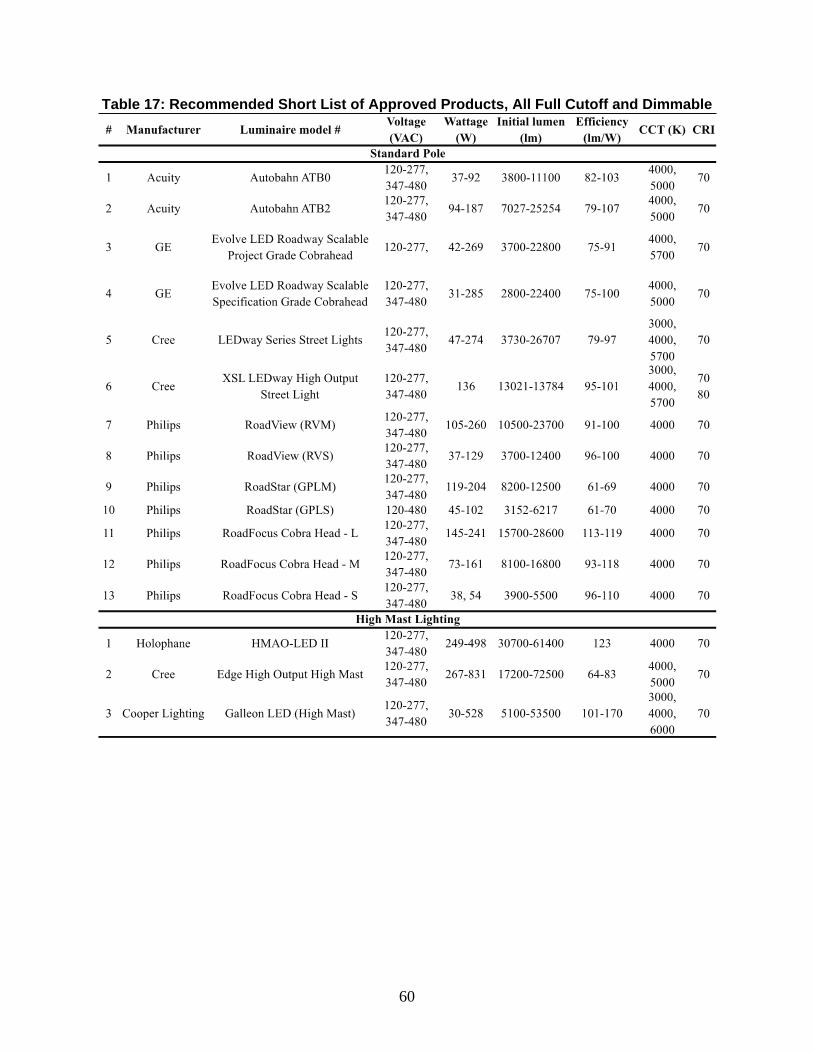
60
Table 17: Recommended Short List of Approved Products, All Full Cutoff and Dimmable
61
Chapter 6: Potential Payback Evaluation
6.1 Introduction
The research team conducted economic studies on potential payoff evaluation of all LED
roadway lighting systems listed in the Approved Products List (APL). Such evaluation includes
estimation of initial, operating and maintenance costs, cost-benefit analysis on a lifetime cycle
basis, and payback period calculations. The results will be recommended for internal use by the
KDOT employees and districts and cities in Kansas, or other authorized users. The results are not
available to vendors or manufacturers.
As a result, this manual includes a lighting economics calculator developed in the
economic studies. The goal of the lighting economics calculator is to provide KDOT a useable
spreadsheet in order to estimate the costs and payback periods of implementing a new LED
roadway lighting system. The spreadsheet is based off of several changeable assumptions that
can be adapted to a particular project. The user has the ability to customize many factors,
including: 1) operating hours, 2) luminaire quantity, 3) maintenance cost, 4) luminaire
installation costs, 5) luminaire prices, 6) average lifecycle, and 7) electricity/demand costs,
among others.
6.2 Implementation Cost Analysis and Results
A lighting economics calculator was then developed to compare the short list products to
their equivalent existing HPS luminaire counterparts, for an assumed project size of 1,000
luminaires. The goal of the lighting economics calculator was to provide KDOT a useable
spreadsheet to estimate the costs and payback time periods of implementing a new LED roadway
lighting system in Kansas. The lighting economics calculator was designed to allow the user to
make necessary changes of design input that could be adapted to a particular project, including
(a) operating hours, (b) average lifecycle, (c) luminaire quantity, (d) luminaire price, (e)
maintenance cost, (f) luminaire installation cost, and (g) electricity/demand cost. The KDOT
lighting specialists can reuse the spreadsheet for a variety of projects across the state. Design
inputs for different projects will automatically update the cost analysis results.
62
The lighting economics calculator was developed based on some presumptions, including
lifecycle of the roadway lighting system, its annual operating hours, typical specifications of the
pre-existing lighting systems, average maintenance and installation costs, prices of the LED and
HPS roadway luminaires, and energy rates charged by the local electric utility provider. These
presumptions came from the specifications of the 83 LED luminaires on the APL, the electric
utility provider, and reviews of some case studies from states that have already implemented new
LED roadway lighting systems to replace their existing systems. These states include Missouri
[35], Minnesota [36], Arizona, and California. The presumptions are detailed as follows.
The overall lighting economics calculator was based on a reasonable 12-year lifecycle for
the roadway lighting system, calculated with a minimum useful life of 50,000 hours for the LED
luminaires on the APL and the presumed annual operating hours. The operating hours for the
roadway luminaires were based on operation times of approximately ½ hour before sunset and ½
hour after sunrise, estimated to be 11 hours per day for 365 days, totaling 4,015 hours per year.
Note that the useful life of the existing HPS luminaires is often 20,000 hours, and 10,000 hours
for the existing high-mast metal halide luminaires installed in Kansas. As a result, re-lamping of
the existing HID roadway luminaires is expected over the 12-year lifecycle.
In this calculator, the pre-existing standard pole luminaires were the typical 150 W HPS
with a typical pole spacing of 150 ft and a typical lumen output of typically 16,000 lm. The pre-
existing high-mast lights were the typical 400 W Metal Halide luminaires with a typical
mounting height of 100 ft and a typical lumen output of 32,000 lm. Both lighting systems are
commonly mounted in Kansas. The replacement LED luminaires used in the calculators were
those from the APL short list (including 13 standard pole lights and three high-mast lights) with
minimum wattage and lumen output that could pass the photometric requirements of the codes
and standards as listed in Table 2. Note that the actual wattages of the HID and LED lighting
systems would be a bit more than the lamp wattages considering the extra power consumed by
the electronic devices like the ballasts or drivers.
The average maintenance cost ($225/luminaire) and installation cost ($110/luminaire,
$800/pole) for Kansas roadway lighting were used, based on the RS Means [37]. The price of
LED luminaires was calculated from a normalized average cost of $4 per Watt, based on the
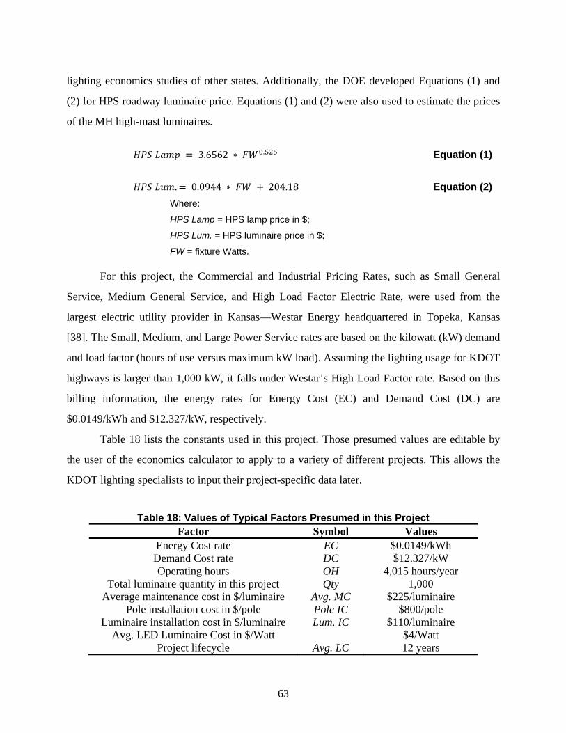
63
lighting economics studies of other states. Additionally, the DOE developed Equations (1) and
(2) for HPS roadway luminaire price. Equations (1) and (2) were also used to estimate the prices
of the MH high-mast luminaires.
3.6562 ∗ . Equation (1)
. 0.0944 ∗ 204.18 Equation (2)
Where:
HPS Lamp = HPS lamp price in $;
HPS Lum. = HPS luminaire price in $;
FW = fixture Watts.
For this project, the Commercial and Industrial Pricing Rates, such as Small General
Service, Medium General Service, and High Load Factor Electric Rate, were used from the
largest electric utility provider in Kansas—Westar Energy headquartered in Topeka, Kansas
[38]. The Small, Medium, and Large Power Service rates are based on the kilowatt (kW) demand
and load factor (hours of use versus maximum kW load). Assuming the lighting usage for KDOT
highways is larger than 1,000 kW, it falls under Westar’s High Load Factor rate. Based on this
billing information, the energy rates for Energy Cost (EC) and Demand Cost (DC) are
$0.0149/kWh and $12.327/kW, respectively.
Table 18 lists the constants used in this project. Those presumed values are editable by
the user of the economics calculator to apply to a variety of different projects. This allows the
KDOT lighting specialists to input their project-specific data later.
Table 18: Values of Typical Factors Presumed in this Project Factor Symbol Values
Energy Cost rate EC $0.0149/kWh Demand Cost rate DC $12.327/kW Operating hours OH 4,015 hours/year
Total luminaire quantity in this project Qty 1,000 Average maintenance cost in $/luminaire Avg. MC $225/luminaire
Pole installation cost in $/pole Pole IC $800/pole Luminaire installation cost in $/luminaire Lum. IC $110/luminaire
Avg. LED Luminaire Cost in $/Watt $4/Watt Project lifecycle Avg. LC 12 years
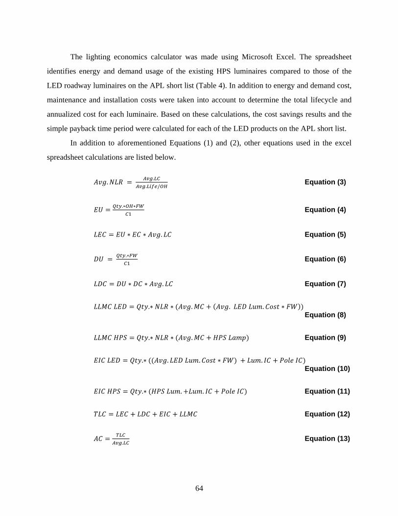
64
The lighting economics calculator was made using Microsoft Excel. The spreadsheet
identifies energy and demand usage of the existing HPS luminaires compared to those of the
LED roadway luminaires on the APL short list (Table 4). In addition to energy and demand cost,
maintenance and installation costs were taken into account to determine the total lifecycle and
annualized cost for each luminaire. Based on these calculations, the cost savings results and the
simple payback time period were calculated for each of the LED products on the APL short list.
In addition to aforementioned Equations (1) and (2), other equations used in the excel
spreadsheet calculations are listed below.
.
.
. / Equation (3)
.∗ ∗ Equation (4)
∗ ∗ . Equation (5)
.∗ Equation (6)
∗ ∗ . Equation (7)
.∗ ∗ . . . ∗ Equation (8)
.∗ ∗ . Equation (9)
.∗ . . ∗ . Equation (10)
.∗ . . Equation (11)
Equation (12)
. Equation (13)
65
. Equation (14)
. Equation (15)
Equation (16)
∗ . Equation (17)
Equation (18)
Where:
HPS = high pressure sodium
LED = light-emitting discharge
NLR = number of lifecycle lamp replacements
EU = energy usage in kWh/year
C1 = constant = 1000 Watts/kW
LEC = lifecycle energy cost in $
DU = demand usage in kW/year
LDC = lifecycle demand cost in $
LLMC = lifecycle lamp maintenance cost in $
EIC = initial equipment and installation cost in $
TLC = total lifecycle cost in $
AC = annualized cost in $
AECS = annual energy cost savings in $
ASPS = annual cost savings per streetlight in $
TAS = total annual savings in $
LCS = lifecycle cost savings in $
SPB = simple payback in years
Using the lighting economics calculator, the cost savings and simple payback time period
were calculated for the 13 standard and three high-mast LED luminaires in Table 19, and then
compared to their HID luminaire counterparts—a pre-existing standard pole 150 Watt HPS
luminaire and a pre-existing high-mast 400 Watt HPS luminaire—for a project size of 1,000
luminaires. Table 19 shows the minimum wattages and corresponding initial lumens of the LED
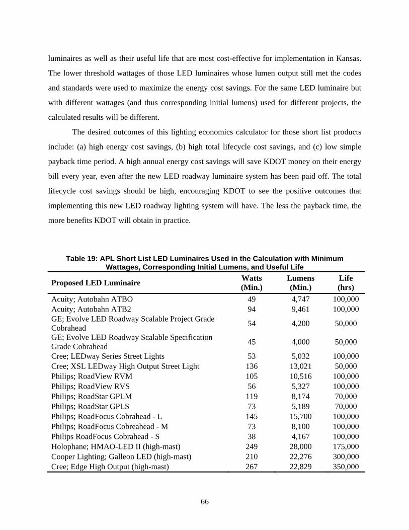
66
luminaires as well as their useful life that are most cost-effective for implementation in Kansas.
The lower threshold wattages of those LED luminaires whose lumen output still met the codes
and standards were used to maximize the energy cost savings. For the same LED luminaire but
with different wattages (and thus corresponding initial lumens) used for different projects, the
calculated results will be different.
The desired outcomes of this lighting economics calculator for those short list products
include: (a) high energy cost savings, (b) high total lifecycle cost savings, and (c) low simple
payback time period. A high annual energy cost savings will save KDOT money on their energy
bill every year, even after the new LED roadway luminaire system has been paid off. The total
lifecycle cost savings should be high, encouraging KDOT to see the positive outcomes that
implementing this new LED roadway lighting system will have. The less the payback time, the
more benefits KDOT will obtain in practice.
Table 19: APL Short List LED Luminaires Used in the Calculation with Minimum
Wattages, Corresponding Initial Lumens, and Useful Life
Proposed LED Luminaire Watts (Min.)
Lumens (Min.)
Life (hrs)
Acuity; Autobahn ATBO 49 4,747 100,000 Acuity; Autobahn ATB2 94 9,461 100,000 GE; Evolve LED Roadway Scalable Project Grade Cobrahead 54 4,200 50,000
GE; Evolve LED Roadway Scalable Specification Grade Cobrahead 45 4,000 50,000
Cree; LEDway Series Street Lights 53 5,032 100,000 Cree; XSL LEDway High Output Street Light 136 13,021 50,000 Philips; RoadView RVM 105 10,516 100,000 Philips; RoadView RVS 56 5,327 100,000 Philips; RoadStar GPLM 119 8,174 70,000 Philips; RoadStar GPLS 73 5,189 70,000 Philips; RoadFocus Cobrahead - L 145 15,700 100,000 Philips; RoadFocus Cobreahead - M 73 8,100 100,000 Philips RoadFocus Cobrahead - S 38 4,167 100,000 Holophane; HMAO-LED II (high-mast) 249 28,000 175,000 Cooper Lighting; Galleon LED (high-mast) 210 22,276 300,000 Cree; Edge High Output (high-mast) 267 22,829 350,000
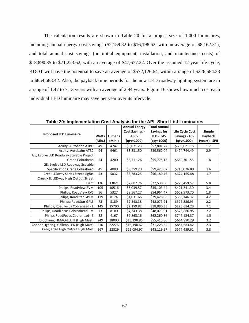
67
The calculation results are shown in Table 20 for a project size of 1,000 luminaires,
including annual energy cost savings ($2,159.82 to $16,198.62, with an average of $8,162.31),
and total annual cost savings (on initial equipment, installation, and maintenance costs) of
$18,890.35 to $71,223.62, with an average of $47,677.22. Over the assumed 12-year life cycle,
KDOT will have the potential to save an average of $572,126.64, within a range of $226,684.23
to $854,683.42. Also, the payback time periods for the new LED roadway lighting system are in
a range of 1.47 to 7.13 years with an average of 2.94 years. Figure 16 shows how much cost each
individual LED luminaire may save per year over its lifecycle.
Table 20: Implementation Cost Analysis for the APL Short List Luminaires
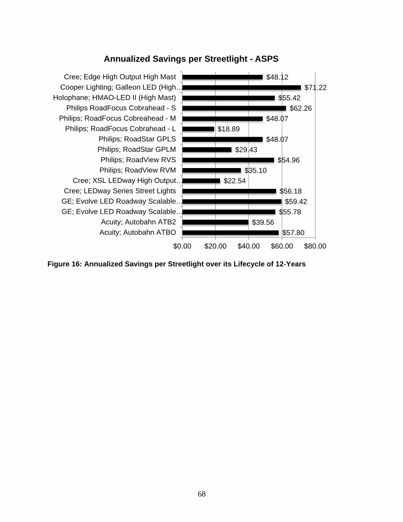
68
Figure 16: Annualized Savings per Streetlight over its Lifecycle of 12-Years
$57.80$39.56
$55.78$59.42
$56.18$22.54
$35.10$54.96
$29.43$48.07
$18.89$48.07
$62.26$55.42
$71.22$48.12
$0.00 $20.00 $40.00 $60.00 $80.00
Acuity; Autobahn ATBOAcuity; Autobahn ATB2
GE; Evolve LED Roadway Scalable…GE; Evolve LED Roadway Scalable…Cree; LEDway Series Street Lights
Cree; XSL LEDway High Output…Philips; RoadView RVMPhilips; RoadView RVS
Philips; RoadStar GPLMPhilips; RoadStar GPLS
Philips; RoadFocus Cobrahead - LPhilips; RoadFocus Cobreahead - M
Philips RoadFocus Cobrahead - SHolophane; HMAO-LED II (High Mast)
Cooper Lighting; Galleon LED (High…Cree; Edge High Output High Mast
Annualized Savings per Streetlight - ASPS
69
Chapter 7: How to Use the Selected LED Illumination Systems in Kansas
The selected qualified LED roadway luminaires on the APL, especially the short-listed
highly recommended luminaires with cost-effectiveness analysis, are ready to be implemented on
Kansas roads by KDOT and local districts and cities. This section summarizes the protocol and
guidelines on using the selected LED illumination systems, including:
a. Responsibilities of the KDOT divisions and districts.
b. Eligibility and warrants for KDOT and the six districts of Kansas to
install and maintain LED lighting systems.
c. Submission of the request for LED illumination and the process.
d. Guidelines on construction and maintenance of the LED roadway
luminaires.
e. LED roadway lighting inspection and servicing on the project sites.
They are detailed below.
7.1 Responsibilities
This section outlines the responsibilities of the KDOT divisions and districts in regard to
the selection, evaluation, installation, inspection, and maintenance of different types of LED
roadway lighting systems in Kansas. The responsibilities may slightly change over time in the
future.
7.1.1 Division of Transportation Planning
The Division of Transportation Planning in the Bureau of Transportation Safety &
Technology (BTST) will prepare policies, procedures, and standards for LED lighting systems;
develop and maintain LED lighting agreement forms; review and process plans, specifications,
and estimates for LED lighting projects; assist districts with design, construction, and
maintenance problems associated with LED lighting systems; review and approve shop drawings
for LED standard pole lighting and LED high-mast lighting assemblies (unless the district
chooses to handle the matter); assist districts with luminaire pole shop drawings and submittal

70
review of LED lighting; and conduct electrical and illumination design training. The contact is
below.
Highway Lighting Specialist
Bureau of Transportation Safety & Technology
Phone: (785) 296-0356
7.1.2 Division of Engineering and Design
The Division of Engineering and Design will assist the KDOT lighting specialist and
relevant engineers in the design of the structure, lighting poles and footing, details of pole
changes, etc. The contact is below.
Signing and Lighting Structures Engineer
Phone: (785) 296-4316
7.1.3 Districts
The districts in Kansas will be responsible for LED lighting projects constructed within
their district, regarding the following tasks.
Review lighting and electrical field changes.
Construct LED illumination projects in accordance with plans.
Maintain LED illumination systems.
Operate LED illumination systems.
Ensure that standard designs are compatible with and applicable to plans.
Prepare and submit FAA Form 7460-1 “Airway-Highway Clearance
Form.”
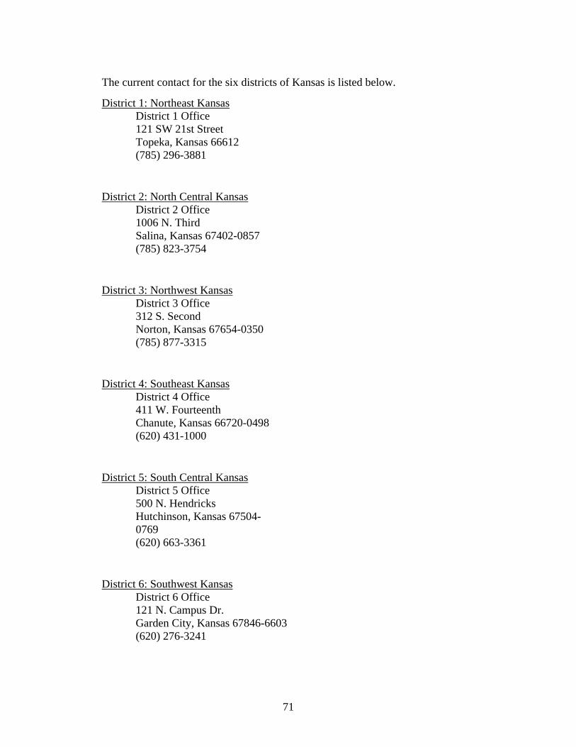
71
The current contact for the six districts of Kansas is listed below.
District 1: Northeast Kansas District 1 Office 121 SW 21st Street Topeka, Kansas 66612 (785) 296-3881
District 2: North Central Kansas District 2 Office 1006 N. Third Salina, Kansas 67402-0857 (785) 823-3754
District 3: Northwest Kansas District 3 Office 312 S. Second Norton, Kansas 67654-0350 (785) 877-3315
District 4: Southeast Kansas District 4 Office 411 W. Fourteenth Chanute, Kansas 66720-0498 (620) 431-1000
District 5: South Central Kansas District 5 Office� 500 N. Hendricks� Hutchinson, Kansas 67504-0769� (620) 663-3361
District 6: Southwest Kansas District 6 Office 121 N. Campus Dr. Garden City, Kansas 67846-6603 (620) 276-3241
72
7.2 Eligibility and Warrant
This section describes for different types of LED lighting systems (e.g., standard poles
and high-mast lighting), which roadways are eligible for those systems, and the conditions that
warrant each system. KDOT can only install and maintain LED lighting systems on eligible
roadways where the conditions warrant such installation. However, meeting of the warrants
does not obligate the KDOT and districts to provide LED lighting (e.g., due to other
considerations like high costs or restrictive subjective values for local use). The eligibility
requirements and warranting criteria to specify the types of highways eligible for the spending of
state funds on proposed LED roadway lighting systems are thus identified. Such eligibility
requirements and warrants are intended to assist the KDOT and local districts in considering
LED lighting on Kansas roads.
7.2.1 Eligibility
Eligibility covers the requirements specify the types of highways eligible for the spending
of Kansas state funds on each type of LED lighting system (e.g., standard pole lighting, high-
mast lighting). The major highway types in Kansas currently desirable for implementation of
LED lighting include:
Freeways — continuous freeway lighting
Interchanges — partial or complete interchange lighting
Other highways — street lighting
Other highways — intersection lighting
Table 21 summarizes the eligibility requirements for installation of LED lighting systems
on different types of roadways in Kansas. Note that in Kansas, 5000 is coded for urban areas of
average daily traffic (ADT) of 5000, likewise, 3000 is coded for suburban areas, and 1000 is
coded for rural areas.
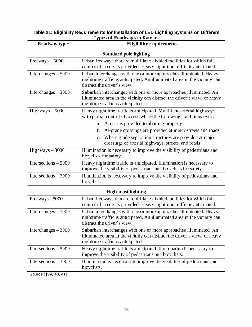
73
Table 21: Eligibility Requirements for Installation of LED Lighting Systems on Different Types of Roadways in Kansas
Roadway types Eligibility requirements
Standard pole lighting Freeways – 5000 Urban freeways that are multi-lane divided facilities for which full
control of access is provided. Heavy nighttime traffic is anticipated. Interchanges – 5000 Urban interchanges with one or more approaches illuminated. Heavy
nighttime traffic is anticipated. An illuminated area in the vicinity can distract the driver’s view.
Interchanges – 3000 Suburban interchanges with one or more approaches illuminated. An illuminated area in the vicinity can distract the driver’s view, or heavy nighttime traffic is anticipated.
Highways – 5000 Heavy nighttime traffic is anticipated. Multi-lane arterial highways with partial control of access where the following conditions exist:
a. Access is provided to abutting property b. At-grade crossings are provided at minor streets and roads c. Where grade separation structures are provided at major
crossings of arterial highways, streets, and roads Highways – 3000 Illumination is necessary to improve the visibility of pedestrians and
bicyclists for safety. Intersections – 5000 Heavy nighttime traffic is anticipated. Illumination is necessary to
improve the visibility of pedestrians and bicyclists for safety. Intersections – 3000 Illumination is necessary to improve the visibility of pedestrians and
bicyclists.
High-mast lighting Freeways - 5000 Urban freeways that are multi-lane divided facilities for which full
control of access is provided. Heavy nighttime traffic is anticipated. Interchanges – 5000 Urban interchanges with one or more approaches illuminated. Heavy
nighttime traffic is anticipated. An illuminated area in the vicinity can distract the driver’s view.
Interchanges – 3000 Suburban interchanges with one or more approaches illuminated. An illuminated area in the vicinity can distract the driver’s view, or heavy nighttime traffic is anticipated.
Intersections – 5000 Heavy nighttime traffic is anticipated. Illumination is necessary to improve the visibility of pedestrians and bicyclists.
Intersections – 3000 Illumination is necessary to improve the visibility of pedestrians and bicyclists.
Source : [39, 40, 41]
74
7.2.2 Warrants
Warrants are the criteria used to justify the need for and expense of LED lighting at
eligible locations (Table 21). To determine if an eligible location meets the relevant warrant,
KDOT assesses roadway conditions in terms of criteria called “cases.” These cases are coded for
ease of reference (i.e., CFL-1, CIL-2, PIL-1, MHL-2). When roadway conditions meet or exceed
one or more of the relevant cases, then the roadway in question warrants the LED lighting—in
other words, the warrant is met. After the warrant is met, KDOT may enter into a partnership
agreement with the city or local government (if necessary) and program the financing [25, 39,
40].
In Kansas, the following cases will be adopted for warrants of LED illumination for
continuous freeway lighting (CFL), complete interchange lighting (CIL), partial interchange
lighting (PIL), non-freeway lighting (NFL), and high-mast lighting (MHL). Such warrants could
be further justified for modification in case of local conditions, such as frequent fog, ice, snow,
roadway geometry, ambient lighting zones, sight distance, signing, etc. [25].
7.2.2.1 Continuous Freeway Lighting (CFL)
A continuous freeway lighting system often uses standard pole lights to provide relatively
uniform lighting on all main lanes and direct connections. Note that it is not expected in the near
future that continuous freeway LED lighting would be used in Kansas. However, this manual
still includes continuous freeway lighting for future expansion. Continuous freeway LED
lighting should be considered for all median barriers on roadway facilities in urban areas. In rural
areas each location must be individually evaluated as to its need for illumination. Table 22 lists
the warranting conditions for continuous freeway lighting (CFL) in Kansas.
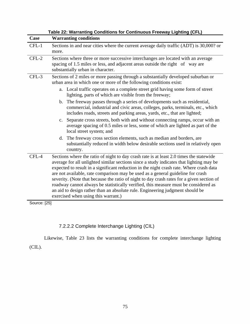
75
Table 22: Warranting Conditions for Continuous Freeway Lighting (CFL) Case Warranting conditions CFL-1 Sections in and near cities where the current average daily traffic (ADT) is 30,000? or
more. CFL-2 Sections where three or more successive interchanges are located with an average
spacing of 1.5 miles or less, and adjacent areas outside the right�of�way are substantially urban in character.
CFL-3 Sections of 2 miles or more passing through a substantially developed suburban or urban area in which one or more of the following conditions exist:
a. Local traffic operates on a complete street grid having some form of street lighting, parts of which are visible from the freeway;
b. The freeway passes through a series of developments such as residential, commercial, industrial and civic areas, colleges, parks, terminals, etc., which includes roads, streets and parking areas, yards, etc., that are lighted;
c. Separate cross streets, both with and without connecting ramps, occur with an average spacing of 0.5 miles or less, some of which are lighted as part of the local street system; and
d. The freeway cross section elements, such as median and borders, are substantially reduced in width below desirable sections used in relatively open country.
CFL-4 Sections where the ratio of night to day crash rate is at least 2.0 times the statewide average for all unlighted similar sections since a study indicates that lighting may be expected to result in a significant reduction in the night crash rate. Where crash data are not available, rate comparison may be used as a general guideline for crash severity. (Note that because the ratio of night to day crash rates for a given section of roadway cannot always be statistically verified, this measure must be considered as an aid to design rather than an absolute rule. Engineering judgment should be exercised when using this warrant.)
Source: [25]
7.2.2.2 Complete Interchange Lighting (CIL)
Likewise, Table 23 lists the warranting conditions for complete interchange lighting
(CIL).
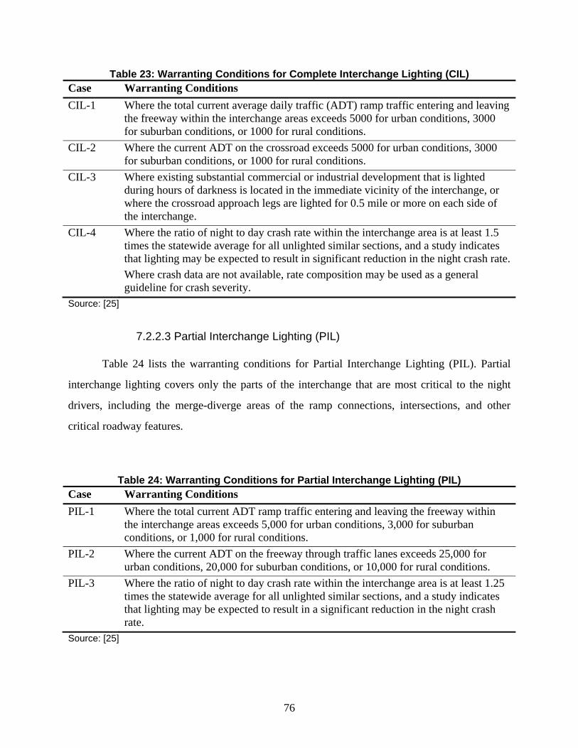
76
Table 23: Warranting Conditions for Complete Interchange Lighting (CIL) Case Warranting Conditions CIL-1 Where the total current average daily traffic (ADT) ramp traffic entering and leaving
the freeway within the interchange areas exceeds 5000 for urban conditions, 3000 for suburban conditions, or 1000 for rural conditions.
CIL-2 Where the current ADT on the crossroad exceeds 5000 for urban conditions, 3000 for suburban conditions, or 1000 for rural conditions.
CIL-3 Where existing substantial commercial or industrial development that is lighted during hours of darkness is located in the immediate vicinity of the interchange, or where the crossroad approach legs are lighted for 0.5 mile or more on each side of the interchange.
CIL-4 Where the ratio of night to day crash rate within the interchange area is at least 1.5 times the statewide average for all unlighted similar sections, and a study indicates that lighting may be expected to result in significant reduction in the night crash rate. Where crash data are not available, rate composition may be used as a general guideline for crash severity.
Source: [25]
7.2.2.3 Partial Interchange Lighting (PIL)
Table 24 lists the warranting conditions for Partial Interchange Lighting (PIL). Partial
interchange lighting covers only the parts of the interchange that are most critical to the night
drivers, including the merge-diverge areas of the ramp connections, intersections, and other
critical roadway features.
Table 24: Warranting Conditions for Partial Interchange Lighting (PIL)
Case Warranting Conditions PIL-1 Where the total current ADT ramp traffic entering and leaving the freeway within
the interchange areas exceeds 5,000 for urban conditions, 3,000 for suburban conditions, or 1,000 for rural conditions.
PIL-2 Where the current ADT on the freeway through traffic lanes exceeds 25,000 for urban conditions, 20,000 for suburban conditions, or 10,000 for rural conditions.
PIL-3 Where the ratio of night to day crash rate within the interchange area is at least 1.25 times the statewide average for all unlighted similar sections, and a study indicates that lighting may be expected to result in a significant reduction in the night crash rate.
Source: [25]
77
7.2.2.4 Non-Freeway Lighting (NFL)
The AASHTO Roadway Lighting Design Guide [25] gives no specific warrants for
continuous lighting of roadways other than freeways (roads with fully controlled access, no at‐
grade intersections), but does suggest some general criteria that may apply when considering the
installation of lighting. Based on AASHTO, in Kansas, lighting of at‐grade intersections is
warranted if the geometric conditions mentioned in the AASHTO Roadway Lighting Design
Guide exist or if one or more of the following conditions exists:
a. Volume — The traffic signal warrant volumes for the minimum
vehicular volume warrant, the interruption of continuous traffic
warrant, or the minimum pedestrian volume warrant are satisfied for
any single hour during conditions other than daylight, excluding the
time period between 6:00 a.m. and 6:00 p.m.
b. Crashes — There are three or more crashes per year occurring during
conditions other than daylight.
c. Intersecting Roadway — The intersecting roadway is lighted.
d. Ambient Light — Illumination in areas adjacent to the intersection
adversely affects the drivers' vision.
e. Channelization — The intersection is channelized and the 85th
percentile approach speed exceeds 40 miles per hour. A continuous
median is not considered as channelization for the purpose of this
warrant.
f. School Crossing — Scheduled events occurring at least once per week
during the school year make it necessary for 100 or more pedestrians
to cross at the school crossing during any single hour in conditions
other than daylight, or a traffic engineering study indicates a need for
lighting.
g. Signalization — The intersection is signalized.
h. Flashing Beacons — The intersection has a flashing beacon.
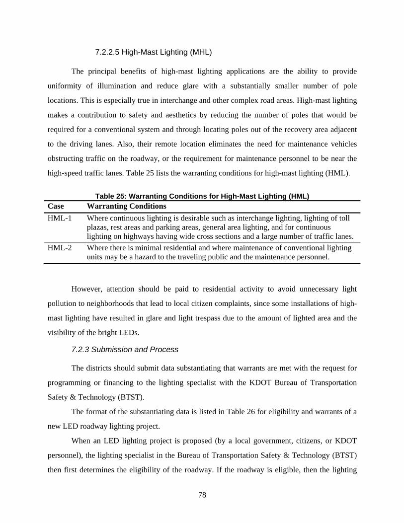
78
7.2.2.5 High-Mast Lighting (MHL)
The principal benefits of high-mast lighting applications are the ability to provide
uniformity of illumination and reduce glare with a substantially smaller number of pole
locations. This is especially true in interchange and other complex road areas. High-mast lighting
makes a contribution to safety and aesthetics by reducing the number of poles that would be
required for a conventional system and through locating poles out of the recovery area adjacent
to the driving lanes. Also, their remote location eliminates the need for maintenance vehicles
obstructing traffic on the roadway, or the requirement for maintenance personnel to be near the
high-speed traffic lanes. Table 25 lists the warranting conditions for high-mast lighting (HML).
Table 25: Warranting Conditions for High-Mast Lighting (HML)
Case Warranting Conditions HML-1 Where continuous lighting is desirable such as interchange lighting, lighting of toll
plazas, rest areas and parking areas, general area lighting, and for continuous lighting on highways having wide cross sections and a large number of traffic lanes.
HML-2 Where there is minimal residential and where maintenance of conventional lighting units may be a hazard to the traveling public and the maintenance personnel.
However, attention should be paid to residential activity to avoid unnecessary light
pollution to neighborhoods that lead to local citizen complaints, since some installations of high-
mast lighting have resulted in glare and light trespass due to the amount of lighted area and the
visibility of the bright LEDs.
7.2.3 Submission and Process
The districts should submit data substantiating that warrants are met with the request for
programming or financing to the lighting specialist with the KDOT Bureau of Transportation
Safety & Technology (BTST).
The format of the substantiating data is listed in Table 26 for eligibility and warrants of a
new LED roadway lighting project.
When an LED lighting project is proposed (by a local government, citizens, or KDOT
personnel), the lighting specialist in the Bureau of Transportation Safety & Technology (BTST)
then first determines the eligibility of the roadway. If the roadway is eligible, then the lighting
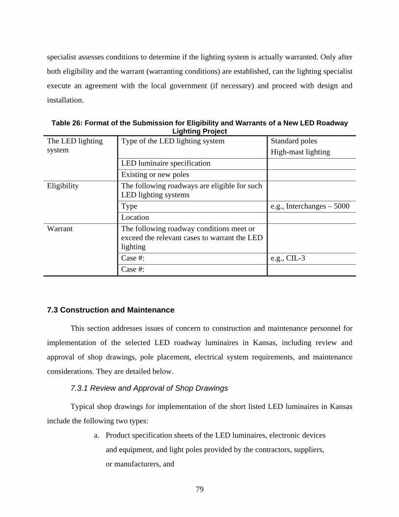
79
specialist assesses conditions to determine if the lighting system is actually warranted. Only after
both eligibility and the warrant (warranting conditions) are established, can the lighting specialist
execute an agreement with the local government (if necessary) and proceed with design and
installation.
Table 26: Format of the Submission for Eligibility and Warrants of a New LED Roadway
Lighting Project The LED lighting system
Type of the LED lighting system Standard poles High-mast lighting
LED luminaire specification Existing or new poles
Eligibility The following roadways are eligible for such LED lighting systems
Type e.g., Interchanges – 5000 Location
Warrant The following roadway conditions meet or exceed the relevant cases to warrant the LED lighting
Case #: e.g., CIL-3 Case #:
7.3 Construction and Maintenance
This section addresses issues of concern to construction and maintenance personnel for
implementation of the selected LED roadway luminaires in Kansas, including review and
approval of shop drawings, pole placement, electrical system requirements, and maintenance
considerations. They are detailed below.
7.3.1 Review and Approval of Shop Drawings
Typical shop drawings for implementation of the short listed LED luminaires in Kansas
include the following two types:
a. Product specification sheets of the LED luminaires, electronic devices
and equipment, and light poles provided by the contractors, suppliers,
or manufacturers, and
80
b. The installation and coordination drawings of the electrical systems of
the new or retrofit roadway lighting projects.
Suppliers must submit shop drawings for LED roadway luminaires and their supportive
electronic devices and lighting poles on purchase requisition for the review and approval. For
breakaway poles, manufacturers are required to submit shop drawings with the structural
strength test results and the breakaway certification [40].
Shop drawings for implementation of new LED luminaires on Kansas roadways at the
district level may be reviewed and approved by the districts with assistance from the lighting
specialist of the KDOT Bureau of Transportation Safety & Technology (BTST) for both contract
projects and district-oriented purchase requisitions. Shop drawings for roadway light poles may
also be reviewed and approved by the districts with coordination of the KDOT Division of
Engineering and Design and the Bureau of Transportation Safety & Technology (BTST).
Shop drawings for high-mast lighting needs to be reviewed by the lighting specialist with
the Bureau of Transportation Safety & Technology (BTST) in coordination with the KDOT
Division of Engineering and Design and the districts where the high-mast lighting is installed.
Districts desiring to review the shop drawings themselves may include a general note in the plans
to that effect. However, due to the complicated and critical nature of high-mast assemblies, it is
recommended that the Bureau of Transportation Safety & Technology (BTST) in coordination
with the KDOT Division of Engineering and Design review these shop drawings.
Shop drawings should be marked as “approved” or “approved except as noted” or
“returned for correction.” Approval marking should be on the drawing itself instead of only by
an accompanying letter [40].
7.3.2 Pole Placement Guidelines
Most of the LED luminaires will be mounted on the top of the existing poles on Kansas
roads unless a new construction is considered for using new poles. Whether new poles are
installed or not depends on the need of new poles for optimal light distribution on the roadway
pavement and the corresponding layout of the luminaires, which will be judged jointly by the
lighting specialist with the KDOT Bureau of Transportation Safety & Technology (BTST), the
81
Division of Engineering and Design, as well as the district where the project is located. Once
new poles are to be installed, the pole placement should follow the guidelines as follows [25]:
a. Structural supports—poles for lighting units should be designed and
located so that they do not distract the attention of the motorists or
interfere with their view of the roadway and other important roadway
features. Supports should be placed so that they do not obstruct the
view of signs.
b. Height restriction. The federal aviation administration may have
certain highest restrictions for lighting poles place adjacent to airports
and in their landing zones.
c. Locating structural supports for lighting units within a median area can
have multiple advantages.
i. Reduce half of the required lighting poles for house side
lighting
ii. Reduce the amount of wiring
iii. Lighting otherwise wasted on the house side is used instead on
the opposite roadway
iv. Reduce construction and maintenance costs
v. Improve visibility on the high-speed lanes
d. Gore areas—locating poles within the clear zone at a gore area is not
usually desirable, unless located behind or atop a longitudinal traffic
barrier or behind a crash cushion. In Kansas, poles need to be 35 ft
height or more, and must be out of the clear zone.
7.3.3 Electrical System Requirements
Construction and maintenance of the electrical systems of the LED roadway lighting
should abide by the latest National Electrical Code and the AASHTO publication entitled
“Standard Specifications for Structural Supports for Highway Signs, Luminaires, and Traffic
Signals” for wiring, disconnection, grounding, and voltage drop.
82
7.3.4 Maintenance Considerations
LED lighting system has reduced maintenance loads due to its elongated life and robust
performance in wide range of roadway environments. Major maintenance considerations of the
LED roadway lighting include luminaire dirt depreciation, lamp lumen depreciation, support
structure maintenance, electrical distribution and control system maintenance, and the
replacement of the LED luminaires and electronic devices at the end of their useful life.
Maintenance of LED illumination systems on Kansas roads is usually provided by cities
and districts under agreement with the KDOT. However, any maintenance problems involving
electrical and illumination design and materials should be brought to the attention of the lighting
specialist of the Bureau of Transportation Safety & Technology (BTST) so that possible
solutions can be provided or alterations can be made on this manual.
LED luminaires often have a useful life of 50,000-100,000 hours or more (> about 12
years). Considering the LED technologies upgrade in every 2-3 years, those LED roadway
luminaires will be replaced at their end of life with new generation of technology. Group re-
lamping on a regular schedule of 3-5 years is no longer needed. As a result, the costs for labor,
traffic control, and equipment use are expected to be greatly reduced.
Note that LED roadway lighting may have other maintenance needs, such as replacement
of electronic devices (e.g., driver, photosensors, which may have shorter useful life than the
LEDs) and cleaning. Cleaning of the luminaires, which involves wiping the dirt from the LED
lenses, may be performed during a recommended time interval by the Illuminating Engineering
Society or KDOT. This periodic cleaning of the fixtures reduces the depreciation of light due to
the accumulation of dirt and allows the delivery of more light per lighting dollar.
At the end of its useful life, replacement LED fixtures for standard pole or high-mast
lighting must be obtained by special order. Each fixture could be replaced with an upgraded
generation. The order should be reviewed and approved by the lighting specialist of the Bureau
of Transportation Safety & Technology (BTST) to make sure the critical photometric
performance of the new fixture will be satisfactory, with assistance from the University of
Kansas lighting research laboratory.
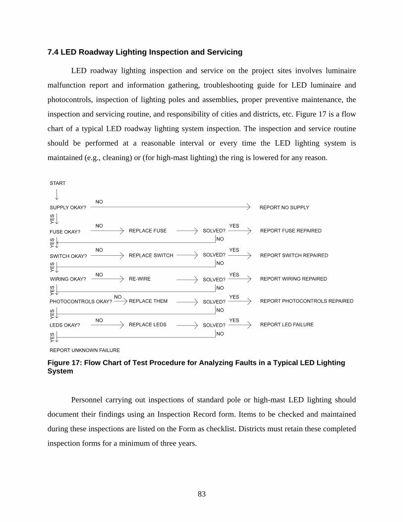
83
7.4 LED Roadway Lighting Inspection and Servicing
LED roadway lighting inspection and service on the project sites involves luminaire
malfunction report and information gathering, troubleshooting guide for LED luminaire and
photocontrols, inspection of lighting poles and assemblies, proper preventive maintenance, the
inspection and servicing routine, and responsibility of cities and districts, etc. Figure 17 is a flow
chart of a typical LED roadway lighting system inspection. The inspection and service routine
should be performed at a reasonable interval or every time the LED lighting system is
maintained (e.g., cleaning) or (for high-mast lighting) the ring is lowered for any reason.
Figure 17: Flow Chart of Test Procedure for Analyzing Faults in a Typical LED Lighting System
Personnel carrying out inspections of standard pole or high-mast LED lighting should
document their findings using an Inspection Record form. Items to be checked and maintained
during these inspections are listed on the Form as checklist. Districts must retain these completed
inspection forms for a minimum of three years.
84
Inspection and service of the standard pole or high-mast LED lighting assemblies, by
agreement, are the maintenance responsibility of a city and district. This work may be performed
by the city or its agent. When this inspection and servicing is performed by the city or its agent,
districts should occasionally check that the work is performed correctly. Districts should provide
a copy of the shop drawings, submittals, and “as built” plans to cities that are maintaining high-
mast lighting. Further assistance with LED lighting inspection and service may be obtained from
the lighting specialist of the Bureau of Transportation Safety & Technology (BTST).
7.5 Lighting Curfews
This section provides guidance on the use of modern controls to turn on/off or dim the
selected LED roadway lighting systems on the approved product list (APL) as permitted by
reduced traffic flow, favorable weather conditions, and other local conditions for energy savings,
greater flexibility in resource allocation, and reduction of light pollution like light-trespass and
sky glow [25]. However, for officials implementing such options in Kansas, KDOT and local
cities should be aware of its consequences and conduct meaningful studies of costs and benefits
in advance [40].
7.5.1 Background
Over 50% of all motor vehicle fatalities occur in darkness even though only 25% of all
travel occurs at night [42]. Warrants for lighting are empirically derived and based on traffic
volume. It is generally accepted that lighting reduces crashes when traffic volumes are high.
However, the frequencies and severities of road crashes are dependent on a host of geometric and
traffic factors including the volume of traffic utilizing the road, the road’s capacity, and the
complexity of the driver’s visual search task [42].
Motor vehicle crash data from the National Highway Traffic Safety Administration’s
Fatality Analysis Reporting System (FARS) [43] and the General Estimates System (GES) [44]
show that 90% of fatal and injury crashes that occur on the roadway are multiple vehicle crashes,
where lighting should be placed. However, the number of overall crashes reduces substantially
after midnight on weekdays and after 4:00 a.m. on weekends. At these late hours, most of the
crashes are single vehicle off roadway crashes, where continuous lighting may not help except
85
only at decision making points such as ramp gores, intersections, and merge areas. It may be
reasonable to turn off the continuous roadway lighting or dim the complete/partial interchange
lighting when traffic volumes subside.
On the other hand, crash rates can increase where lighting systems are turned off or every
other luminaire is turned off (rather than dimming) resulting in poor uniformity ratios. The issue
of drivers’ needs and safety versus energy conservation efforts should be closely examined by
KDOT when considering curfews. Poorly conceived conservation efforts may contribute to
excessive increases in traffic crashes and operational problems resulting in higher overall costs.
7.5.2 Reasons for Curfews
Government entities around the world are considering lighting curfews for the following
reasons [25]:
Low late-hours traffic volumes. AASHTO warrants for highway lighting
are based, among other things, on traffic volume. When the high traffic
volumes and high usage drop off in later hours of the night, it is
reasonable to turn off or dim the LED lighting after such drop-offs.
To free up resources for greater overall safety. Lowering the operational
costs of lighting systems by reducing electrical and maintenance costs
through curfews may allow more lighting systems or other crash
countermeasure to be installed, thereby reducing the overall nighttime
crash rate within the jurisdiction of the master lighting plan.
LED Technology now practical. Modern controls technology of LED
lights, e.g., DALI (digital addressable lighting interface) as a protocol set
out in the technical standard IEC 62386, allows digital and precise control
of individual or groups of LED luminaires at reasonable costs.
Positive study results. Light dimming and turn-off curfews are viable
options for management of public lighting systems, including roadway
lighting. Although past studies showed unfavorable increases in traffic
crash rates because of turning off lighting, those studies were performed
on conventional lighting systems where the HID lamps were turned off or
86
partially turned off for the entire nighttime period. New LED lighting
systems could be continuously dimmed to a reasonable low level when the
traffic volumes are low without jeopardizing roadway safety. Yet new
research is needed to validate this conservation potential for Kansas.
Energy savings. Energy costs are still high. Dimming or turning off LED
lights on Kansas roads may largely reduce energy uses.
Sky glow issues. Sky glow issues are of increasing importance to the
health of citizens and local environments like nocturnal animals.
7.5.3 Considerations Before Implementation
Normal traffic volumes, special events (e.g., regularly scheduled sports events and other
large traffic generators), weather, and other local considerations should be included in the
decision to implement curfews of LED lighting systems in Kansas. For example, reduced
freeway lighting tactics normally should not be implemented before about 11:00 p.m. in most
urban areas, since traffic density typically remains relatively high until that time. Cities with little
or no evening activity might allow an earlier light reduction. Implementation of lighting curfews
should occur through traffic management centers in Kansas and should be monitored to gain
experience as to the best operational procedures [42].
Old light reduction techniques dealing with conventional HID lighting systems during
lighting curfews have a problem that lighting was reduced or eliminated during the entire
nighttime period, rather than only when traffic volume was low. In addition, HID lighting
systems could not be continuously dimmed like modern LED lighting systems do.
By providing full lighting during periods when volumes are high and the roadway
operates near capacity and providing reduced lighting as the traffic decreases, considerable
energy savings could be achieved while still providing the benefits of full or dimmed lighting at
critical locations (e.g., interchanges) and at times (i.e., high volumes) where driver decision-
making is the most critical and the greatest visibility is required [42].
From a safety standpoint, lighting curfew may lower drivers’ hazard detection
performance, which theoretically implies some reduction in safety. However, this implied
87
reduction in safety is statistically significant for all off and one side only lighting tactics that
were commonly used by the conventional HID lighting systems, but may not be statistically
significant for the continuously dimmed tactics that LED lighting systems typically deploy.
Unfortunately, it is not possible at this time to quantify, under LED lighting curfews, the exact
decrease in safety in terms of the frequency of nighttime accidents, the night accident rate, or the
night-to day accident ratio. Further research is needed for an evaluation of the impact of lighting
curfews on long-term installations of LED lighting systems in Kansas [42].
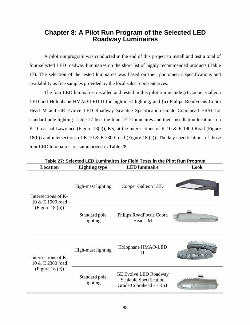
88
Chapter 8: A Pilot Run Program of the Selected LED Roadway Luminaires
A pilot run program was conducted in the end of this project to install and test a total of
four selected LED roadway luminaires on the short list of highly recommended products (Table
17). The selection of the tested luminaires was based on their photometric specifications and
availability as free samples provided by the local sales representatives.
The four LED luminaires installed and tested in this pilot run include (i) Cooper Galleon
LED and Holophane HMAO-LED II for high-mast lighting, and (ii) Philips RoadFocus Cobra
Head–M and GE Evolve LED Roadway Scalable Specification Grade Cobrahead–ERS1 for
standard pole lighting. Table 27 lists the four LED luminaires and their installation locations on
K-10 east of Lawrence (Figure 18(a)), KS, at the intersections of K-10 & E 1900 Road (Figure
18(b)) and intersections of K-10 & E 2300 road (Figure 18 (c)). The key specifications of those
four LED luminaires are summarized in Table 28.
Table 27: Selected LED Luminaires for Field Tests in the Pilot Run Program
Location Lighting type LED luminaire Look
Intersections of K-10 & E 1900 road
(Figure 18 (b))
High-mast lighting Cooper Galleon LED
Standard pole lighting
Philips RoadFocus Cobra Head - M
Intersections of K-10 & E 2300 road
(Figure 18 (c))
High-mast lighting Holophane HMAO-LED II
Standard pole lighting
GE Evolve LED Roadway Scalable Specification
Grade Cobrahead - ERS1
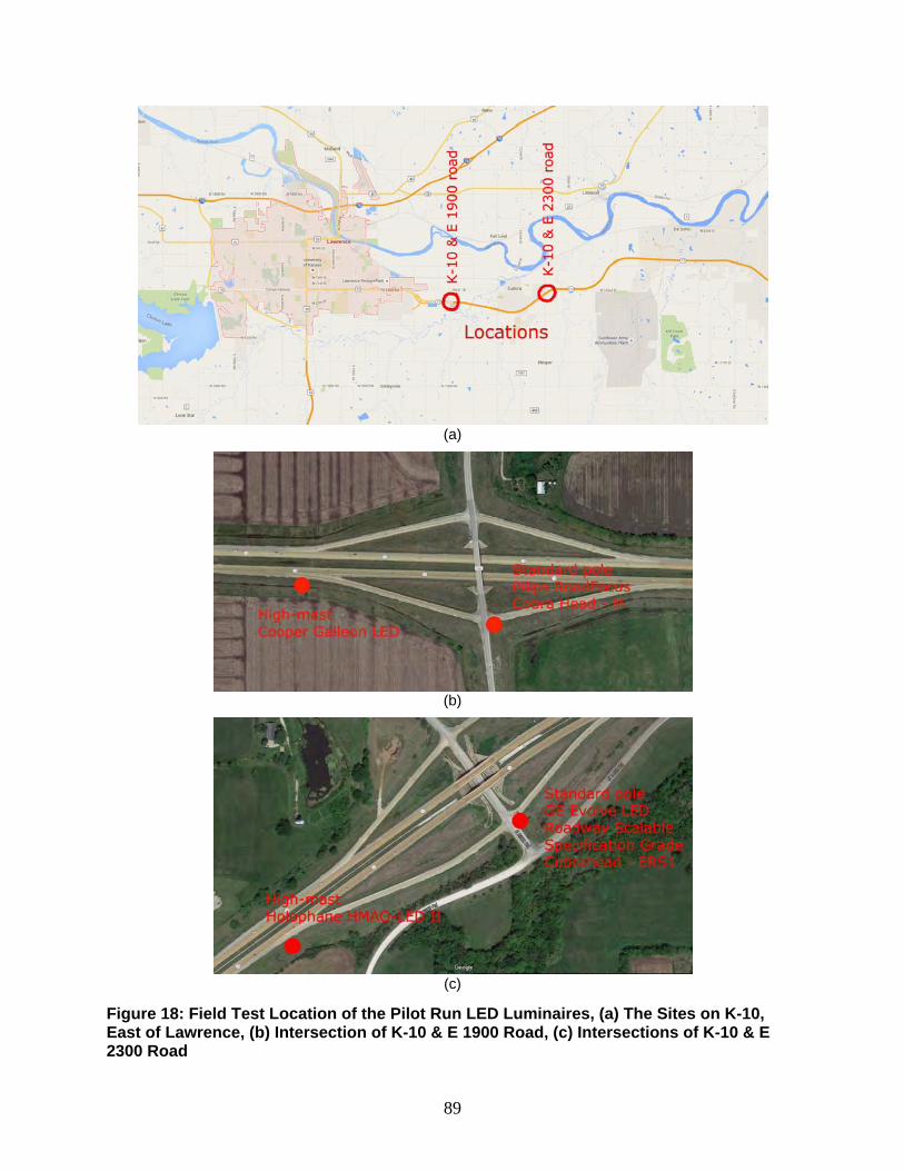
89
(a)
(b)
(c)
Figure 18: Field Test Location of the Pilot Run LED Luminaires, (a) The Sites on K-10, East of Lawrence, (b) Intersection of K-10 & E 1900 Road, (c) Intersections of K-10 & E 2300 Road
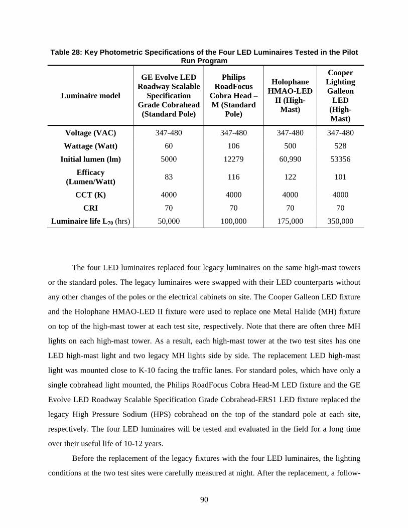
90
Table 28: Key Photometric Specifications of the Four LED Luminaires Tested in the Pilot Run Program
Luminaire model
GE Evolve LED Roadway Scalable
Specification Grade Cobrahead (Standard Pole)
Philips RoadFocus
Cobra Head – M (Standard
Pole)
Holophane HMAO-LED
II (High-Mast)
Cooper Lighting Galleon
LED (High-Mast)
Voltage (VAC) 347-480 347-480 347-480 347-480
Wattage (Watt) 60 106 500 528
Initial lumen (lm) 5000 12279 60,990 53356
Efficacy (Lumen/Watt) 83 116 122 101
CCT (K) 4000 4000 4000 4000
CRI 70 70 70 70
Luminaire life L70 (hrs) 50,000 100,000 175,000 350,000
The four LED luminaires replaced four legacy luminaires on the same high-mast towers
or the standard poles. The legacy luminaires were swapped with their LED counterparts without
any other changes of the poles or the electrical cabinets on site. The Cooper Galleon LED fixture
and the Holophane HMAO-LED II fixture were used to replace one Metal Halide (MH) fixture
on top of the high-mast tower at each test site, respectively. Note that there are often three MH
lights on each high-mast tower. As a result, each high-mast tower at the two test sites has one
LED high-mast light and two legacy MH lights side by side. The replacement LED high-mast
light was mounted close to K-10 facing the traffic lanes. For standard poles, which have only a
single cobrahead light mounted, the Philips RoadFocus Cobra Head-M LED fixture and the GE
Evolve LED Roadway Scalable Specification Grade Cobrahead-ERS1 LED fixture replaced the
legacy High Pressure Sodium (HPS) cobrahead on the top of the standard pole at each site,
respectively. The four LED luminaires will be tested and evaluated in the field for a long time
over their useful life of 10-12 years.
Before the replacement of the legacy fixtures with the four LED luminaires, the lighting
conditions at the two test sites were carefully measured at night. After the replacement, a follow-
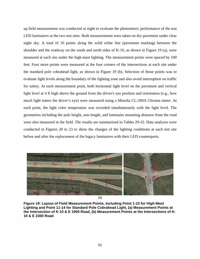
91
up field measurement was conducted at night to evaluate the photometric performance of the test
LED luminaires at the two test sites. Both measurements were taken on dry pavement under clear
night sky. A total of 10 points along the solid white line (pavement marking) between the
shoulder and the roadway on the south and north sides of K-10, as shown in Figure 19 (a), were
measured at each site under the high-mast lighting. The measurement points were spaced by 100
feet. Four more points were measured at the four corners of the intersections at each site under
the standard pole cobrahead light, as shown in Figure 19 (b). Selection of those points was to
evaluate light levels along the boundary of the lighting zone and also avoid interruption on traffic
for safety. At each measurement point, both horizontal light level on the pavement and vertical
light level at 4 ft high above the ground from the driver's eye position and orientation (e.g., how
much light enters the driver’s eye) were measured using a Minolta CL-200A Chroma meter. At
each point, the light color temperature was recorded simultaneously with the light level. The
geometries including the pole height, arm length, and luminaire mounting distance from the road
were also measured in the field. The results are summarized in Tables 29-32. Data analyses were
conducted in Figures 20 to 23 to show the changes of the lighting conditions at each test site
before and after the replacement of the legacy luminaires with their LED counterparts.
(a)
Figure 19: Layout of Field Measurement Points, Including Point 1-10 for High-Mast Lighting and Point 11-14 for Standard Pole Cobrahead Light, (a) Measurement Points at the Intersection of K-10 & E 1900 Road, (b) Measurement Points at the Intersections of K-10 & E 2300 Road
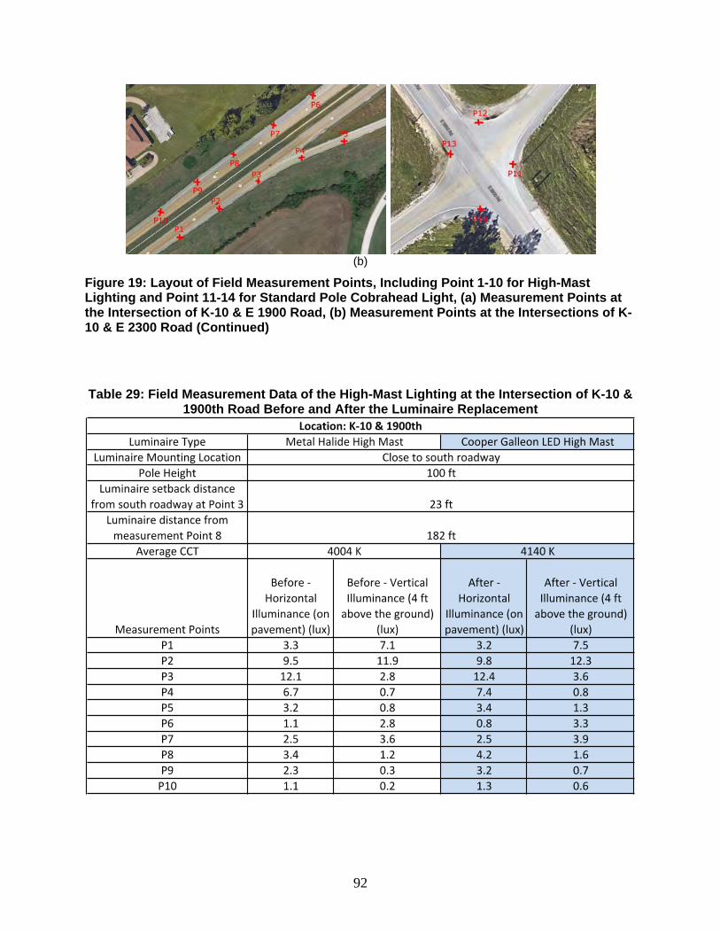
92
(b)
Figure 19: Layout of Field Measurement Points, Including Point 1-10 for High-Mast Lighting and Point 11-14 for Standard Pole Cobrahead Light, (a) Measurement Points at the Intersection of K-10 & E 1900 Road, (b) Measurement Points at the Intersections of K-10 & E 2300 Road (Continued)
Table 29: Field Measurement Data of the High-Mast Lighting at the Intersection of K-10 &
1900th Road Before and After the Luminaire Replacement
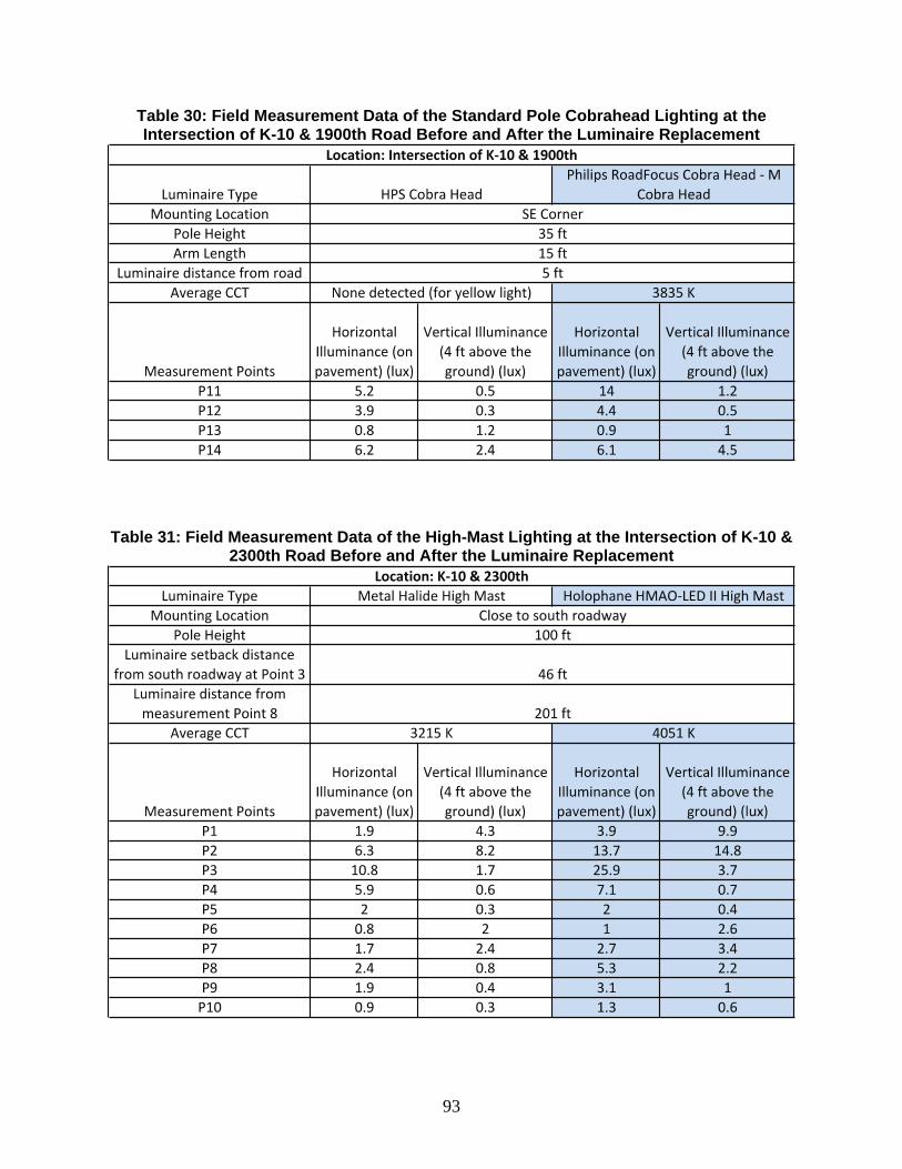
93
Table 30: Field Measurement Data of the Standard Pole Cobrahead Lighting at the Intersection of K-10 & 1900th Road Before and After the Luminaire Replacement
Table 31: Field Measurement Data of the High-Mast Lighting at the Intersection of K-10 &
2300th Road Before and After the Luminaire Replacement
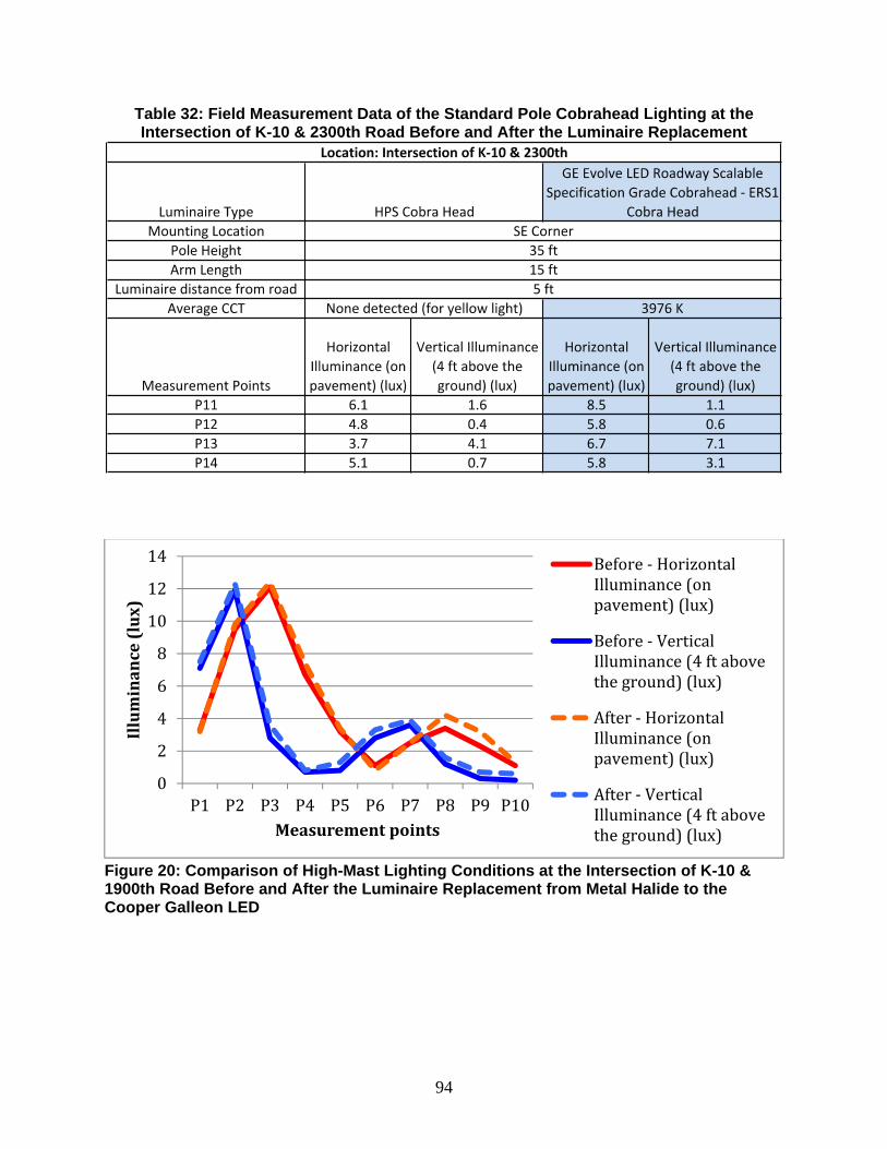
94
Table 32: Field Measurement Data of the Standard Pole Cobrahead Lighting at the Intersection of K-10 & 2300th Road Before and After the Luminaire Replacement
Figure 20: Comparison of High-Mast Lighting Conditions at the Intersection of K-10 & 1900th Road Before and After the Luminaire Replacement from Metal Halide to the Cooper Galleon LED
0
2
4
6
8
10
12
14
P1 P2 P3 P4 P5 P6 P7 P8 P9 P10
Illuminance(lux)
Measurementpoints
Before‐HorizontalIlluminance(onpavement)(lux)
Before‐VerticalIlluminance(4ftabovetheground)(lux)
After‐HorizontalIlluminance(onpavement)(lux)
After‐VerticalIlluminance(4ftabovetheground)(lux)
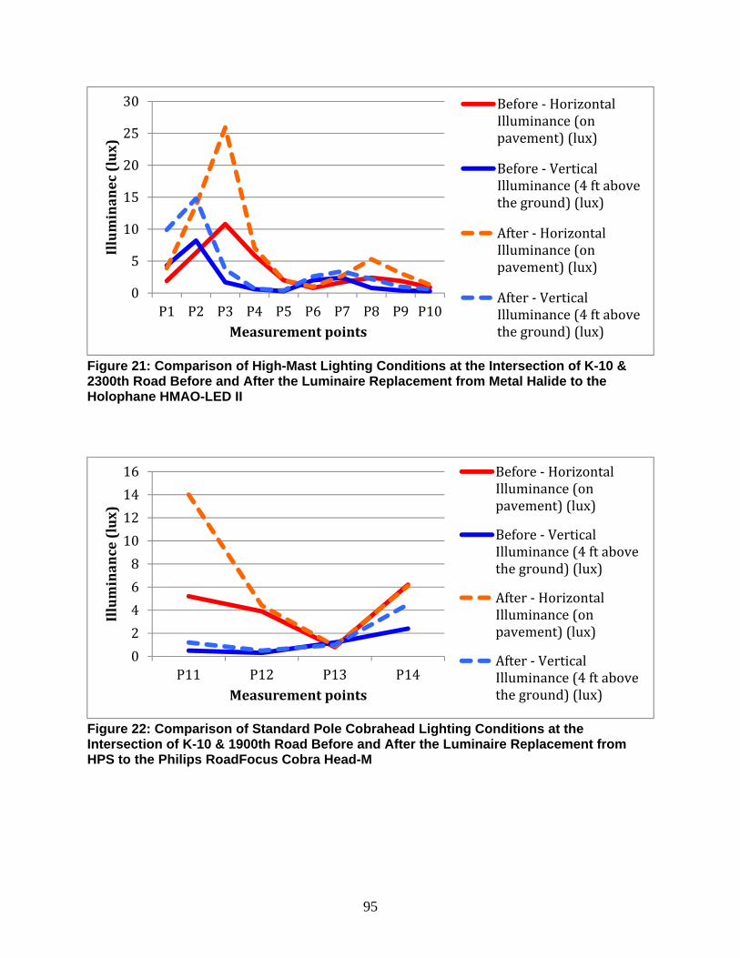
95
Figure 21: Comparison of High-Mast Lighting Conditions at the Intersection of K-10 & 2300th Road Before and After the Luminaire Replacement from Metal Halide to the Holophane HMAO-LED II
Figure 22: Comparison of Standard Pole Cobrahead Lighting Conditions at the Intersection of K-10 & 1900th Road Before and After the Luminaire Replacement from HPS to the Philips RoadFocus Cobra Head-M
0
5
10
15
20
25
30
P1 P2 P3 P4 P5 P6 P7 P8 P9 P10
Illuminanec(lux)
Measurementpoints
Before‐HorizontalIlluminance(onpavement)(lux)
Before‐VerticalIlluminance(4ftabovetheground)(lux)
After‐HorizontalIlluminance(onpavement)(lux)
After‐VerticalIlluminance(4ftabovetheground)(lux)
0
2
4
6
8
10
12
14
16
P11 P12 P13 P14
Illuminance(lux)
Measurementpoints
Before‐HorizontalIlluminance(onpavement)(lux)
Before‐VerticalIlluminance(4ftabovetheground)(lux)
After‐HorizontalIlluminance(onpavement)(lux)
After‐VerticalIlluminance(4ftabovetheground)(lux)
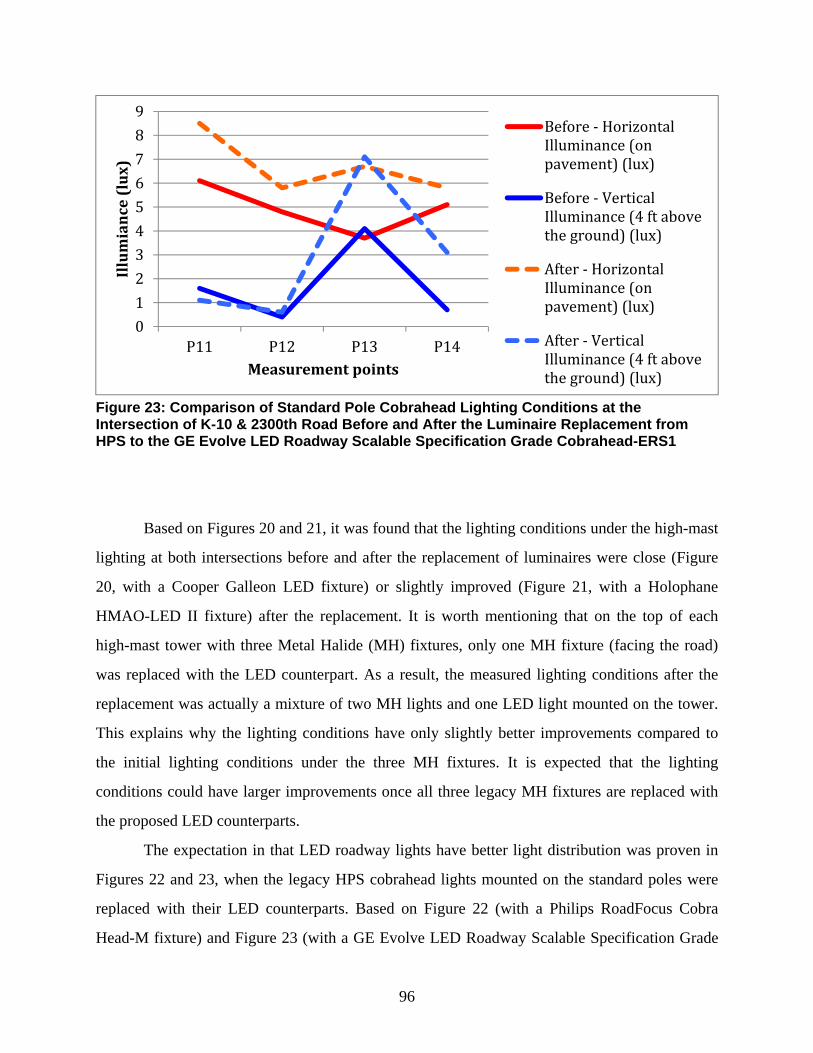
96
Figure 23: Comparison of Standard Pole Cobrahead Lighting Conditions at the Intersection of K-10 & 2300th Road Before and After the Luminaire Replacement from HPS to the GE Evolve LED Roadway Scalable Specification Grade Cobrahead-ERS1
Based on Figures 20 and 21, it was found that the lighting conditions under the high-mast
lighting at both intersections before and after the replacement of luminaires were close (Figure
20, with a Cooper Galleon LED fixture) or slightly improved (Figure 21, with a Holophane
HMAO-LED II fixture) after the replacement. It is worth mentioning that on the top of each
high-mast tower with three Metal Halide (MH) fixtures, only one MH fixture (facing the road)
was replaced with the LED counterpart. As a result, the measured lighting conditions after the
replacement was actually a mixture of two MH lights and one LED light mounted on the tower.
This explains why the lighting conditions have only slightly better improvements compared to
the initial lighting conditions under the three MH fixtures. It is expected that the lighting
conditions could have larger improvements once all three legacy MH fixtures are replaced with
the proposed LED counterparts.
The expectation in that LED roadway lights have better light distribution was proven in
Figures 22 and 23, when the legacy HPS cobrahead lights mounted on the standard poles were
replaced with their LED counterparts. Based on Figure 22 (with a Philips RoadFocus Cobra
Head-M fixture) and Figure 23 (with a GE Evolve LED Roadway Scalable Specification Grade
0
1
2
3
4
5
6
7
8
9
P11 P12 P13 P14
Illumiance(lux)
Measurementpoints
Before‐HorizontalIlluminance(onpavement)(lux)
Before‐VerticalIlluminance(4ftabovetheground)(lux)
After‐HorizontalIlluminance(onpavement)(lux)
After‐VerticalIlluminance(4ftabovetheground)(lux)
97
Cobrahead-ERS1 fixture), both the horizontal light level on the pavement and the vertical light
level at the height of typical driver’s eyes were increased after the replacement of fixtures.
Moreover, the visual perception of the roadway lighting conditions at both intersections
was enhanced (visually brighter) with better color temperature of the light, especially when the
HPS cobrahead lights (which emit yellowish light without color temperature measured by the
meter) were replaced with the LED lights with a color temperature close to 4000 K.
98
Chapter 9: Conclusions and Discussions
The research project was aimed to assist the Kansas Department of Transportation
(KDOT) in the development of a highway LED illumination manual for guiding the upcoming
implementation of successful LED roadway lighting systems in Kansas to install at new
locations and replace the existing HID roadway lighting systems. This project has five major
outcomes, including:
a. The desired specifications of the LED roadway lighting systems that
could be used in Kansas for roadway lighting and an approved product
list (APL) with 83 LED luminaires.
b. The selection of a short list of 13 standard pole and three high-mast
LED luminaires highly recommended for implementation in Kansas.
c. The development of a lighting economics calculator for those APL
LED luminaires if implemented in Kansas, and the implementation
cost analyses for the APL short-listed LED luminaires as examples.
d. Use of the selected LED illumination systems in Kansas covering the
responsibilities, eligibility and warrant, construction and maintenance,
LED roadway lighting inspection and servicing, and lighting curfew.
e. A pilot run program of the selected LED roadway luminaires installed
on K-10. Those LED luminaires will be tested and evaluated in the
field over their useful life of 10-12 years.
The five deliverables contribute to the major content of the new Kansas Roadway LED
Illumination Manual. They will assist Kansas in the implementation of LED roadway lighting
systems using the most highly recommended luminaires that show the most potential for energy
and total cost savings, with a short payback time period.
In particular, the 83 LED luminaires on the APL, including the highly recommended
short list of 13 standard pole and three high-mast LED luminaires, are expected to provide the
KDOT and local cities in Kansas good options of LED lighting systems for practical
implementation of LED roadway lighting in terms of energy efficacy (e.g., 61-170 lm/W), useful
99
life (e.g., 50,000, 100,000 hours, and longer), photometric performance (e.g., lumen output of
4,000-72,500 lm, CCT of 3000-6000 K, light lateral distribution types of III, IV, V, and V-FT,
full cutoff, low BUG ratings, IP ≥ 66), high color rendering performance (CRI ≥ 70), and
advanced digital controls (e.g., continuously dimmable, photoelectric control, spill control). In
addition, based on the example cost-benefit analyses conducted for the APL short list products,
when replacing the HID roadway luminaire counterparts, the APL short listed LED luminaires
may save approximately $18.89 to $71.22 with an average of $47.68 per year per light over their
lifecycle (at least 12 years) with a payback period of 1.5-7.1 years, averagely 2.9 years.
The developed lighting economics calculator is a simple and useful tool for quick
implementation cost analysis on replacing the traditional HID system with a new LED system,
which could be used for any projects of different size in Kansas. It can be used for calculating
factors such as (i) annual energy cost saving, (ii) initial equipment, installation, and maintenance
cost savings, (iii) total annual cost savings, (iv) cost savings per luminaire, (v) life cycle total
cost savings, and (vi) the simple payback time period. The calculator may also be used in other
states as well with appropriate adjustments of inputs, such as localized costs of electricity and
demand, operating hours, average maintenance and installation costs, etc.
While this project presents some useful outcomes, it is important to understand that the
derivation of the deliverables was based upon several presumptions tailored to Kansas uses.
Nonetheless, every LED roadway project is inherently different. A small project may not
have the same benefits as larger-scale projects, as suggested in this research. Without knowing
the specific details of the project that KDOT plans to undertake, the outcomes summarized in
this paper are intended to guide KDOT through the decision making process in general, rather
than present a cut-and-dry design solution. The lighting economics calculator in particular was
designed to allow KDOT lighting specialists to change the design input, to tailor the cost-benefit
analysis for any project in time to come. Moreover, in the lighting economics calculator, energy-
savings rebate rates that vary from time to time were not taken into account, which could have
the potential to save even more money.
100
References
[1] Office of Energy Efficiency and Renewable Energy (EERE). 2012. Energy Savings Potential of Solid-State Lighting in General Illumination Applications. Washington, DC: U.S. Department of Energy.
[2] Office of Energy Efficiency and Renewable Energy (EERE). 2013. Adoption of Light-
Emitting Diodes in Common Lighting Applications. Washington, DC: U.S. Department of Energy.
[3] Office of Energy Efficiency and Renewable Energy (EERE). 2013. Solid State Lighting
Research and Development Multi-Year Program Plan. Washington, DC: U.S. Department of Energy.
[4] Office of Energy Efficiency and Renewable Energy (EERE). 2014. Energy Savings Forecast
of Solid-State Lighting in General Illumination Applications. Washington, DC: U.S. Department of Energy.
[5] U.S. Energy Information Administration (EIA) Independent Statistics and Analysis. 2014.
How Much of U.S. Carbon Dioxide Emissions Are Associated with Electricity Generation? http://www.eia.gov/tools/faqs/faq.cfm?id=77&t=11
[6] Gerdes, Justin. 2013. Los Angeles Completes World's Largest LED Street Light Retrofit.
Forbes. Retrieved June 6, 2015, http://www.forbes.com/sites/justingerdes/ 2013/07/31/los-angeles-completes-worlds-largest-led-street-light-retrofit/
[7] Office of Energy Efficiency and Renewable Energy (EERE). 2011. Energy Savings Estimates
of Light Emitting Diodes in Niche Lighting Applications. Retrieved June 6, 2015, http://apps1.eere.energy.gov/buildings/publications/pdfs/ssl/nichefinalreport_january2011.pdf
[8] Holophane. 2014. Mongoose LED roadway and area lighting luminaire. Retrieved July 21,
2015, http://www.acuitybrandslighting.com/library/HLP/Documents/ otherdocuments/HL-2506%20Mongoose%20LED%20Brochure.pdf
[9] Holophane. n.d. Mongoose LED image gallery [Image of Mongoose LED fixtures alongside
highway]. Retrieved July 21, 2015, http://www.holophane.com/led/MGLED/gfx/Gallery/MGLED-Highway1.jpg
[10] Wikipedia. n.d. High mast lighting used on Ontario highway 401 during the day. Retrieved
July 21, 2015, http://en.wikipedia.org/wiki/High-mast_lighting#/media/ File:Highway_401-Highway_402_interchange.jpg
101
[11] American city and county. 2013. [Image of Maine DOT traffic control electricians installing Holophane luminaires]. Retrieved July 21, 2015, http://americancityandcounty.com/site-files/americancityandcounty.com/files/imagecache/large_img/uploads/2013/09/holophanehrmainedotphoto-2.jpg
[12] Lighting Research Center, Rensselaer Polytechnic Institute. 2004. Light sources and color.
Figure 8. The CIE 1976 chromaticity diagram. Lighting Answers 8(1). Retrieved June 6, 2015, http://www.lrc.rpi.edu/programs/nlpip/lightinganswers/lightsources/whatisCCT.asp
[13] Seesmart LED. n.d. Color temperature scale application. Retrieved July 21, 2015,
http://www.seesmartled.com/kb/choosing_color_temperature/ [14] All LED Lighting. 2013. Retrieved June 6, 2015,
http://img.deusm.com/allledlighting/2013/08/560818/163108_854448.jpg [15] LEDspots. n.d. Color rendering performance. Retrieved July 21, 2015,
http://ledspots.org/color-rendering-index/ [16] Eye Lighting International. n.d. LED distribution types. Retrieved May 16, 2015,
http://www.eyelighting.com/resources/lighting-technology-education/led-basics/led-distribution-types/
[17] Apack. n.d. Street light cutoff classifications. Retrieved May 16, 2015,
http://apack.net/kor/sub/Street_Light.html [18] Praha Lighting. n.d. TM-15 BUG rating. Retrieved May 16, 2015,
http://www.prahalighting.com/miniplatinum/fotometriasmini.html [19] Illuminating Engineering Society (IES). 2011. Addendum A for IES TM-15-11: Backlight,
Uplight, and Glare (BUG) Ratings. http://www.ies.org/PDF/Erratas/TM-15-11BUGRatingsAddendum.pdf
[20] National Electrical Manufacturers Association (NEMA). 2004. ANSI/IEC 60529-2004.
Degrees of Protection Provided by Enclosures (IP Code) (identical national adoption). Rosslyn, VA: NEMA.
[21] DSM&T. n.d. Sample IP rating. Retrieved May 21, 2015,
http://www.dsmt.com/resources/ip-rating-chart [22] Richman, E. 2011. The elusive “life” of LEDs: How TM-21 contributes to the solution.
LEDs Magazine. Retrieved May 21, 2015, http://www.ledsmagazine.com/articles/ 2012/11/the-elusive-life-of-leds-how-tm-21-contributes-to-the-solution-magazine.html
[23] LED Luxor. 2012. Top 10 Benefits of Using LED Lighting. Retrieved June 12, 2015,
http://www.ledluxor.com/top-10-benefits-of-led-lighting
102
[24] Illuminating Engineering Society of North America (IESNA). 2000. American National Standard Practice for Roadway Lighting. ANSI/IESNA RP-8-00. New York, NY: IESNA.
[25]American Association of State Highway and Transportation Officials (AASHTO). 2005.
Roadway Lighting Design Guide. GL-6. Washington, DC: AASHTO. [26] Lutkevich, Paul, Don McLean, and Joseph Cheung. 2012. FHWA Lighting Handbook.
Office of Safety. Washington, DC: Federal Highway Administration. [27] International Commission on Illumination (CIE). 2007. Road Transport Lighting for
Developing Countries. CIE 180-2007. Vienna, Austria: CIE. [28] Illuminating Engineering Society of North America (IESNA). 2011. Technical
Memorandum on Light Trespass: Research, Results, and Recommendations. TM-11-00. New York, NY: IESNA.
[29] Illuminating Engineering Society of North America (IESNA). 2014. Lighting for Exterior
Environments: An IESNA Recommended Practice. IESNA RP-33-14. New York, NY: IESNA.
[30] Illuminating Engineering Society of North America (IESNA). 2011. Luminaire
Classification System for Outdoor Luminaires. IES TM-15-11. New York, NY: IESNA. [31] Illuminating Engineering Society of North America (IESNA). 2011. The Lighting
Handbook: Reference and Application. New York, NY: IESNA. [32] Illuminating Engineering Society of North America (IESNA). 2014. Roadway Lighting.
ANSI/IESNA RP-8-14. New York, NY: IESNA. [33] International Commission on Illumination (CIE). 1995. Industrial Colour-difference
Evaluation. CIE 116-1995. Vienna, Austria: CIE. [34] Kansas Department of Transportation (KDOT). 2003. Kansas Roundabout Guide. Chapter 7
- Traffic Design. Topeka, KS: KDOT. [35] Long, Suzanna, Ruwen Qin, Curt Elmore, Tom Ryan, and Sean Schmidt. 2011. LED
Roadway Luminaires Evaluation (TRyy1101) Final Report. No. cmr12-011. Jefferson City, MO: Missouri Department of Transportation. Retrieved May 21, 2015, http://library.modot.mo.gov/rdt/reports/tryy1101/cmr12011tryy1101.pdf
103
[36] Energy Management Solutions, Inc. 2012. Cost-Benefit Analysis of Energy Efficient Technologies Available for Use in Roadway Lighting. St. Paul, MN: Minnesota Department of Commerce. Retrieved July 13, 2015, https://www.cards.commerce.state.mn.us/CARDS/security/search.do?method=showPoup&documentId=%7BB9337BBA-09D3-43D3-81AB-0279CF28FB0F%7D& documentTitle=40203&documentType=6
[37] RSMeans. 2014. RSMeans Electrical Cost Data. 37th edition. Norwell, MA: RSMeans. [38] Westar Energy. 2013. Small General Service, Medium General Service, and High Load
Factor Electric Rate Summary. Retrieved June 16, 2015, https://www.westarenergy.com/ Portals/0/Resources/Documents/Commercial%20Rates%20South.pdf
[39] Minnesota Department of Transportation. 2010. Roadway Lighting Design Manual. St.
Paul, MN: Minnesota DOT. [40] Texas Department of Transportation. 2003. Highway Illumination Manual. Austin, TX:
Texas DOT. [41] New Hampshire Department of Transportation. 2010. Highway Lighting Design Manual.
Concord, NH: New Hampshire DOT. [42] Staplin, L. K., M. S. Janoff, and L. E. Decina. 1985. Reduced Lighting on Freeways During
Periods of Low Traffic Density. FHWA/RD-86/018. Washington, DC: Federal Highway Administration.
[43] National Highway Traffic Safety Administration (NHTSA). n.d. Fatality Analysis Reporting
System (FARS). Retrieved May 20, 2015, http://www.nhtsa.gov/FARS [44] National Highway Traffic Safety Administration (NHTSA). n.d. NASS General Estimates
System. Retrieved May 20, 2015, http://www.nhtsa.gov/Data/National+Automotive+ Sampling+System+(NASS)/NASS+General+Estimates+System


![Illumination-Aware Age Progressionnovel illumination-aware age progression technique, lever-aging illumination modeling results [1,31], that properly account for scene illumination](https://img.pdfslide.us/doc/110x75/5e72745a0ac7de5cbf4199be/illumination-aware-age-progression-novel-illumination-aware-age-progression-technique.jpg)