Embed Size (px)
Citation preview

Kamloops Business Area

PREFACE
While it is impossible to prevent sediment from leaving disturbed forest lands due to rainfall and snow melt, significant reductions can be realized. This field manual had been developed to assist those in the forestry field who install, maintain, monitor and inspect sediment and erosion measures associated with roads and stream crossings. This document does not address all mitigation measures that are available to implement; however, information has been incorporated to increase the effectiveness of the most common Best Management Practices (BMPs) found in BC Timber Sales forestry applications.
Techniques presented in this manual have been developed from personal experience, research, Erosion Draw 4.0, and teaching about sediment and erosion control. While none of the BMPs will achieve 'Zero Sediment Discharge', correct application, implementation and maintenance can result in significant reductions of sediment in runoff waters. It is expected that the use of this manuol will result in practical and effective control of sediment that may be generated during forestry operations.
Methods outlined in this manual have been designed for uses perscribed in various environmental plans based on variables triggered through the BCTS Risk Matrix. Depending on key variables present at each site location, the risk of activities can be assessed and the corresponding Environmental Management Plan (EMP) or Sediment and Erosion Control Plan (SECP) will be prepared.
This manual is to be used as a guide, and is in no way designed to replace contract/license design specifications if applicable. If specified design parameters have been prescribed, these specifications/prescriptions take prescedence over the methods and techniques presented in this manual. For additional information refer to the Be Timber Sales Environmental Management System, Emergency Response Manual and site specific Emergence Response Plans.

Table of Contents
Drainage Control
Cross Drains & Ditch Blocks Page 1
Crown Road Surface Page 2
Wing Ditches Page 3
Erosion Control
Seeding/Mulching Page 4
Armor Inlet & Outlet of CMP (Non fish bearing streams) Page 5
Surface Roughening Page 6
Cross Ditch Page 7
Waterbar Page 8
De-Compact Road Surface Page 9
Sediment Control
Silt Fence Page 10
In-stream sediment Curtains Page 11
Sediment Diaper Page 12
Typical Temporary Stream Crossing Techniques
with Bank Protection Page 13
Settling Basin Page 14
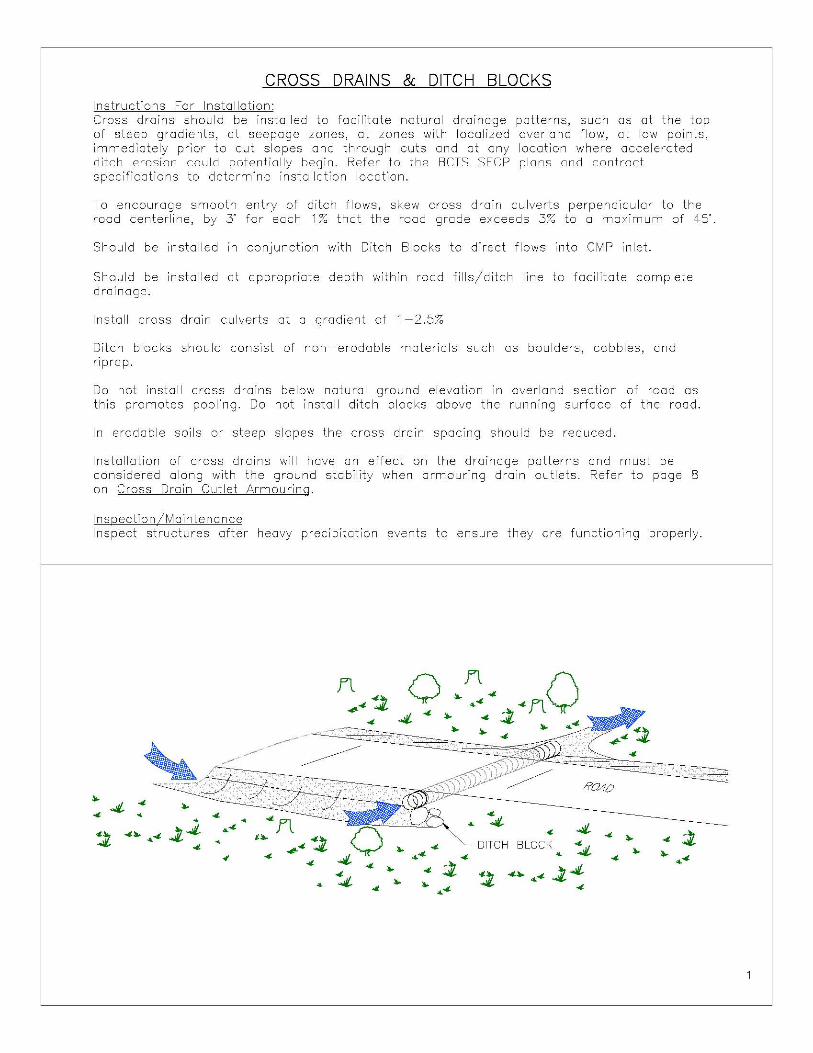
CROSS DRAINS & DITCH BLOCKS Instructions For Installation: Cross drains should be installed to facilitate natural drainage patterns, such as at the top of steep gradients, at seepage zones, at zones with localized overland flow, at low points, immediately prior to cut slopes and through cuts and at any location where accelerated ditch erosion could potentially begin. Refer to the BCTS SEep pions and contract specifications to determine installation location.
To encourage smooth entry of ditch flows, skew cross drain culverts perpendicular to the rood centerline, by 3" for each 1 % that the rood grade exceeds 3% to 0 maximum of 45".
Should be installed In conjunction with Ditch Blocks to direct flows into CMP inlet.
Should be installed at appropriate depth within road fills/ditch line to facilitate complete drainage.
Install cross drain culverts at a gradient of 1-2.5%
Ditch blocks should consist of non-erodable materials such as boulders, cobbles, and riprap.
Do not install cross drains below natural ground elevation in overland section of road as this promotes pooling. Do not install ditch blocks above the running surface of the rood.
In erodable soils or steep slopes the cross drain spacing should be reduced.
Installation of cross drains will have an effect on the drainage patterns and must be considered along with the ground stability when armouring drain outlets. Refer to page B on Cross Drain Outlet Armouring.
Inspection /Maintena nee Inspect structures after heavy precipitation events to ensure they are functioning properly.
"- 4
4 4- • • '!t 4"- ~4-~4
4
• ~4
• <f 4
ROAO
<t 4-DITCH BLOCK ~ "4 "
"-
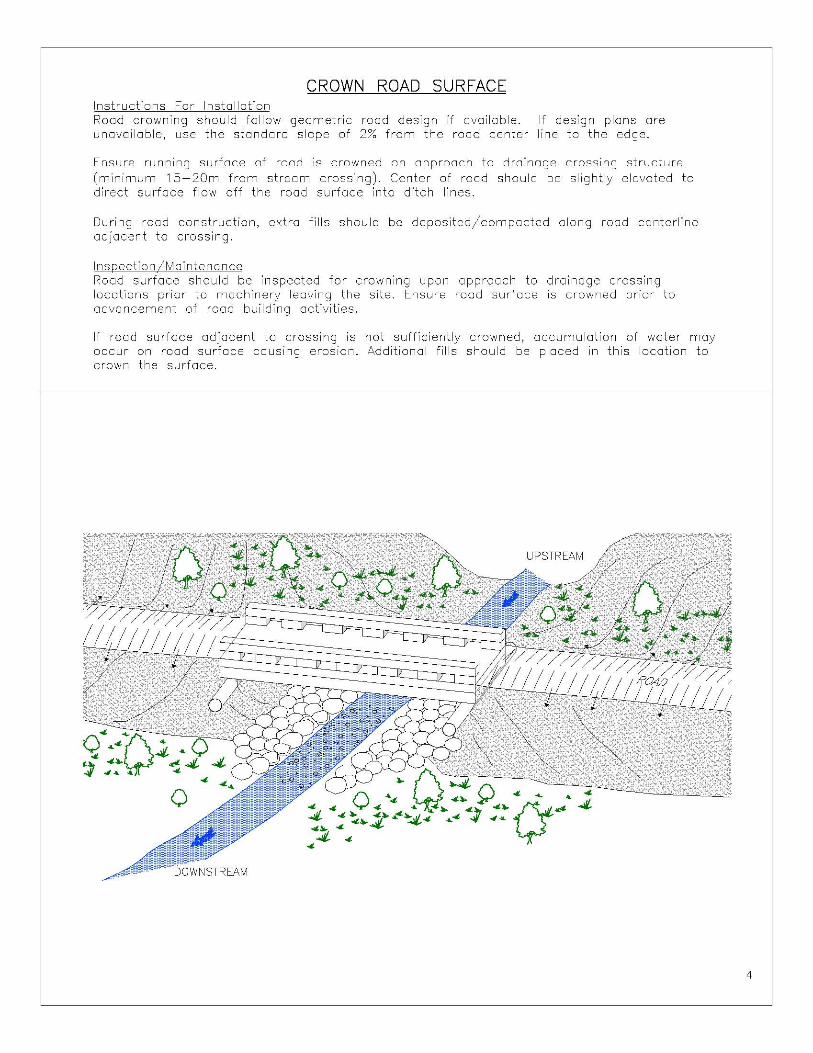
CROWN ROAD SURFACE Instructions For Installation Road crowning should follow geometric road design if available. If design plans are unavailable, use the standard slope of 2% from the rood center line to the edge.
Ensure running surface of rood is crowned on approach to drainage crossing structure (minimum 15-20m from stream crossing). Center of rood should be slightly elevated to direct surface flow off the road surface into ditch lines.
During rood construction, extra fills should be deposited/compacted along rood centerline adjacent to crossing.
Inspection IMaintena nee Road surface should be inspected for crowning upon approach to drainage crossing locations prior to machinery leaving the site. Ensure rood surface is crowned prior to advancement of road building activities.
If road surface adjacent to crossing is not sufficiently crowned, accumulation of water may occur on rood surface causing erosion. Additional fills should be placed in this location to crown the surface.
4

WING DITCHES
Instructions for installation Excavate wing ditches to direct flow out of ditch lines to avoid accumulation of water/velocity causing sediment mobilization.
Construct below ditch grade as wing ditches are gravity fed.
Install as many as terrain allows.
Measures must be taken to ensure that the slopes are capable of withstanding the drainage directed at them. This can be done by lining the ditch (page 2), installing check dams to slow flows (page 3), or ormouring outlets where heavy flows ore anticipated (page 8).
May be associated with cross drains in some cases to get rid of water from both ditch lines.
Inspection IMointeno nee Ensure wing ditch is functioning properly during periods of heavy flow within ditch lines. Excavate/remove debris as necessary.
o~ 4- <t '" ~
WING DITCH
5
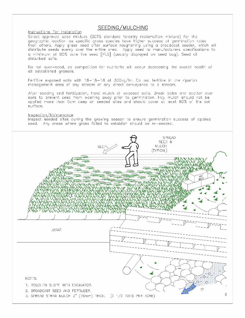
SEEDING Instructions For Installation Select approved seed mixture (BCTS standard forestry reclamation mixture) for the geographic location as specific grass species have higher success of germination rates than others. Apply grass seed after surface roughening using a broadcast seeder, which will distribute seeds evenly over the entire area. Apply seed to manufacturers specifications to a minimum of 80% pure live seed [PLS] (usually displayed on seed bag). Seed all disturbed soils.
Do not over-seed, as competition for nutrients will occur decreasing the overall health of all established grosses.
Fertilize exposed soils with 18-18-18 at 300kg/hr. Do not fertilize in the riparian management area of any stream of any direct conveyance to a stream.
After seeding and fertilization, hand mulch all exposed soils. Break bales and scatter over soils to prevent seed from washing away prior to germination. Hay mulch should not be applied more than Scm deep on seeded sites and should cover at least 80% of the soil surface.
Ins[)ection IMaintena nce Inspect seeded sites during the growing season to ensure germination success of applied seed. Any areas where grass foiled to establish should be re-seeded.
ROAO
NOTES:
1. ROUGHEN SLOPE WITH EXCAVATOR.
2. BROADCAST SEED AND FERTILIZER.
SLO
SPREAD SEED &
MULCH (TYPICAL)
..
3. SPREAD STRAW MULCH 3" (76mm) THICK. (2 1/2 TONS PER ACRE) 6

ARMOR INLET & OUTLET OF CMP (NON-FISH BEARING STREAM) Instructions For Installation Inlets and Outlets of CMPs should be armored accordingly based on the size and flow regime of the drainage. Drainages that exhibit heavy flows should be heavily armored with assorted rip rap, boulders and cobbles.
Place large angular substrates (if available) around inlet and outlet of CMP tight to stream bed. Fill holes with smaller materials once leading edge has been installed. Ensure armor is tight to CMP around inlet and outlet to prevent erosion (inlet) ond undermining during high flows.
Place smaller substrates within stream channel at outlet of CMP to provide additional armoring.
Ensure geotextile collar is installed at inlet of CMP to prevent piping and undermining.
Inspection IMaintena nee Inspect armor after significant rain events and make necessary repairs. Ensure woody debris does not block inlet flow, clean as necessary.
,"c·',
C;::j,;" ,';;.::
"'" "":: ...
lQ ... 4"" j: ... .. 4'" _
',)l:;
."" ';,:"
>,'«
7
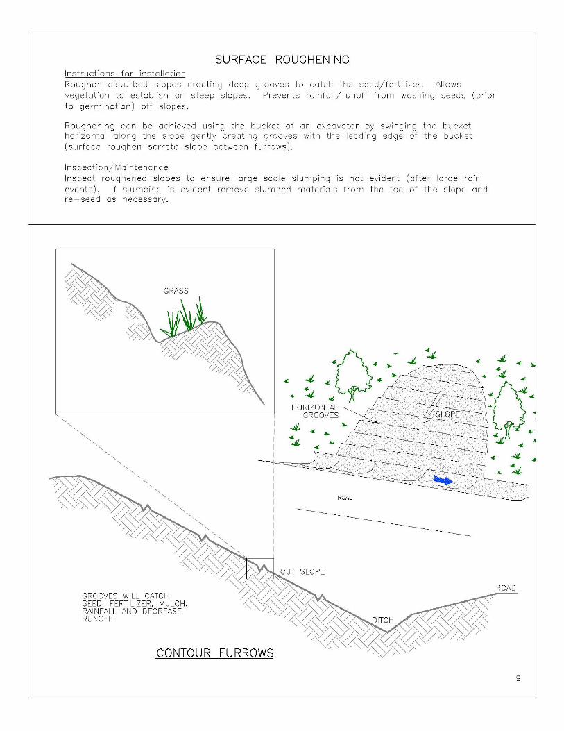
SURFACE ROUGHENING Instructions for installation Roughen disturbed slopes creating deep vegetation to establish on steep slopes. to germination) off slopes.
grooves to catch the seed/fertilizer. Allows Prevents rainfall/runoff from washing seeds (prior
Roughening can be achieved using the bucket of on excavator by swinging the bucket horizontal along the slope gently creating grooves with the leoding edge of the bucket (surface roughen serrate slope between furrows).
Ins[)ection IMaintena nee Inspect roughened slopes to ensure large scale slumping is not evident (after large rain events). If slumping is evident remove slumped materials from the toe of the slope and re-seed as necessary.
GROOVES WILL CATCH SEED, FERTILIZER, MULCH, RAINFALL AND DECREASE RUNOFF
CONTOUR FURROWS
4 .. :Q .... ~ 4: - ~~~ .. ~S HORIZONTAL
GROOVES
4 .... 4:
ROAD
9

CROSS DITCH Instructions For Installation Cross ditches should be installed back from the stream channel across the road prior to the riparian zone of the stream. Ensure sufficient length to prevent passage of surface flow down road grade to deactivated crossing.
Should be installed in areas where road grade slopes towards crossing. Ensure that the slope below the outlet of the drainage structure is stobie, and armour where necessary.
Cross ditch should be excavated to well below the originol grade. It should be skewed so that water flowing through it is not slowed down or made to abruptly change direction, therefore steeper roads require more skew. Ditch gradient should be installed at a minimum of 2%. For ditch lining specifications refer to page 2 and for outlet armouring refer to page 8.
Maintena nee II nspection Should be inspected periodically to en sure measure is functioning properly and not contributing sediment to the stream crossing.
Fix or replace any damaged sections with suitable materials .
."
o. J1.-4- ."
~"'J1.0" ~
-4- ... ~ ..
~ ,. .. • .. ,. • ,. ~ ..
." .. .,,~ ..
..
10

WATER BAR Instructions for installation Excavate road fill materials across entire road surface to facilitate drainage of flows on the surface of the rood. Ensure vehicular access is maintained as well as slope stability below the waterboro
Fills from waterbar are deposited immediately down grade forming a berm.
Armour as necessary after considering the materials present and the slope stability below the waterbar.
Ensure the woterbor does not tronsfer woter out of the ditch line, just off of the roodwoy.
Inspection IMaintena nee Inspect during heavy precipitation events to ensure dimensions of structure are sufficient to remove all flows off road grade.
STABILIZED OUTLET
9" (225mm)
SECTION
2:1 SIDE SLOPES OR FLATTER. 3:1 MAX FOR VEHICLE CROSSING.
SLOPE
11
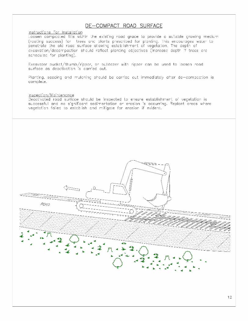
DE-COMPACT ROAD SURFACE Instructions For Installation Loosen compacted fills within the existing road grade to provide a suitable growing medium (rooting success) for trees ond plants prescribed for planting. This encourages water to penetrate the old road surface allowing establishment of vegetation. The depth of excavation/decompactian should reflect planting objectives (increase depth if trees are scheduled for planting).
Excavator bucket/thumb/ripper, or bulldozer with ripper con be used to loosen rood surface as deactivation is carried out.
Planting, seeding and mulching should be carried out immediately after de-compaction is complete.
Inspection IMaintena nee Deactivated road surface should be inspected to ensure establishment of vegetation is successful and no significant sedimentation or erosion is occurring. Replant areas where vegetation failed to establish and mitigate for erosion if evident.
12

SILT FENCE
Instructions for Installation Silt fence sholl be placed on the slope contours to maximize ponding efficiency.
Inspect and repair fence ofter each storm event and remove sediment when necessary. Maximum storage height is 225.
Removed sediment shall be deposited to an area that will not contribute to sediment off-site and con be permanently stabilized.
The silt fence is a temporary feature that must be removed from the site once sufficient vegetation has been established.
Inspection IMointeno nee Ensure silt fence is not clogged (clean as necessary) and remains upright (as installed) after heavy rain events.
EXTRA STRENGTH FILTER FABRIC NEEDED WITHOUT WIRE MESH SUPPORT --,
ATTACH FILTER FABRIC SECURELY TO UPSTREAM SIDE OF POST --I'
STEEL OR WOOD POST
'. " .
. . .. . ,.
:. ./', ~ FLOW ..
. . .
, .
. rI ' '. ..~ .. ,' " /
, \ ~ ",'7 ~;,('~'~"V"<~ O' (3m) ~UM SPACING /)';yNN ,c. yAyNN'> WITH WIRE SUPPORT FENCE
-PONDING HEIGHT
/ A'/ A'/ AV '/('//' / /- 6' (1.8m) MAXIMUM SPACING "<""''''''''''):~ 11/ )." . ' WITHOUT WIRE SUPPORT FENCE
FLOW .. STEEL OR WOOD POST 36" (1 m) HIGH MAX.
~, .. . ... ' .. ~~ /A'0 " . " .. ' :~'\S. 12" MIN. ~ !rt·~ V~Y(*
(300mm) ?2- ~ ///' / )'» f // V <~, '// J
--'------V" 4"x6" (100 X 150mm) TRENCH WITH COMPACTED
TRENCH DETAIL 13
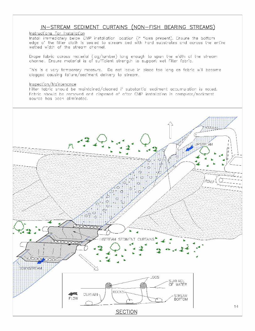
IN-STREAM SEDIMENT CURTAINS (NON-FISH BEARING STREAMS) Instructions For Installation Install immediately below CMP installation location (if flows present). Ensure the bottom edge of the filter cloth is sealed to stream bed with hard substrates and across the entire wetted width of the stream channel.
Drape fabric across material (log/lumber) long enough to span the width of the stream channel. Ensure material is of sufficient strength to support wet filter fabric.
This is a very temporary measure. Do not leave in place too long as fabric will become clogged causing failure/sediment delivery to stream.
Ins[)ection IMaintena nee Filter fabric should be maintained/cleaned if substantial sediment accumulation is noted. Fabric should be removed and disposed of after CMP installation is complete/sediment source has been eliminated.
#44 0 .. 4-
f1 4 4- .. 44- 4-
4-~ 4-.. .. 4-
SEDIMENT
0 .. 44-
<t~ 4-
4 ... ..
' 4 4- ..
4:- .. <t
~ CURTAIN FLOW
SECTION
0 .. 44-
CURTAINS .. <t
<t
~ ~ 4-
LOGS
"
, ..... 44- Ji4
4-
SURFACE OF WATER
STREAM BOTTOM
• 4'" , <I
44-
4-..
14

SEDIMENT DIAPER INSTALLATION Instructions For Installation Cut large piece of geotextile fabric/poly large enough to cover the underside of the existing crossing structure. Fasten to outer stringer logs with nails and wrap under structure to opposite stringer log.
Prior to removing structure, sweep sediments off bridge deck. Carefully lift decking off support structures. Next, remove inner stringers first with sediment diaper still fastened to outer stringers. Finally roll outer stringers together with sediment diaper included. Lift entire unit clear from the stream and away from the channel. Remove diaper once decking is out of the riparian zone of the stream.
Ins[)ection IMaintena nee Replace fabric if damage is apparent.
Ensure sediment diaper is securely attached to log stringers or secured to terroin below (steel bridge). Inspect diaper for damage prior to removal of additional modules if present.
~' -===· 1J/7~ ~ECK I ~STRINGER LOGS
GE::X:E DIAPER NAILED ~~~~~~~~~~~~ TO OUTSIDE STRINGERS & SUSPENDED UNDER DECK
CROSS SECTION VIEW
.. ..
15
o
'" o n:
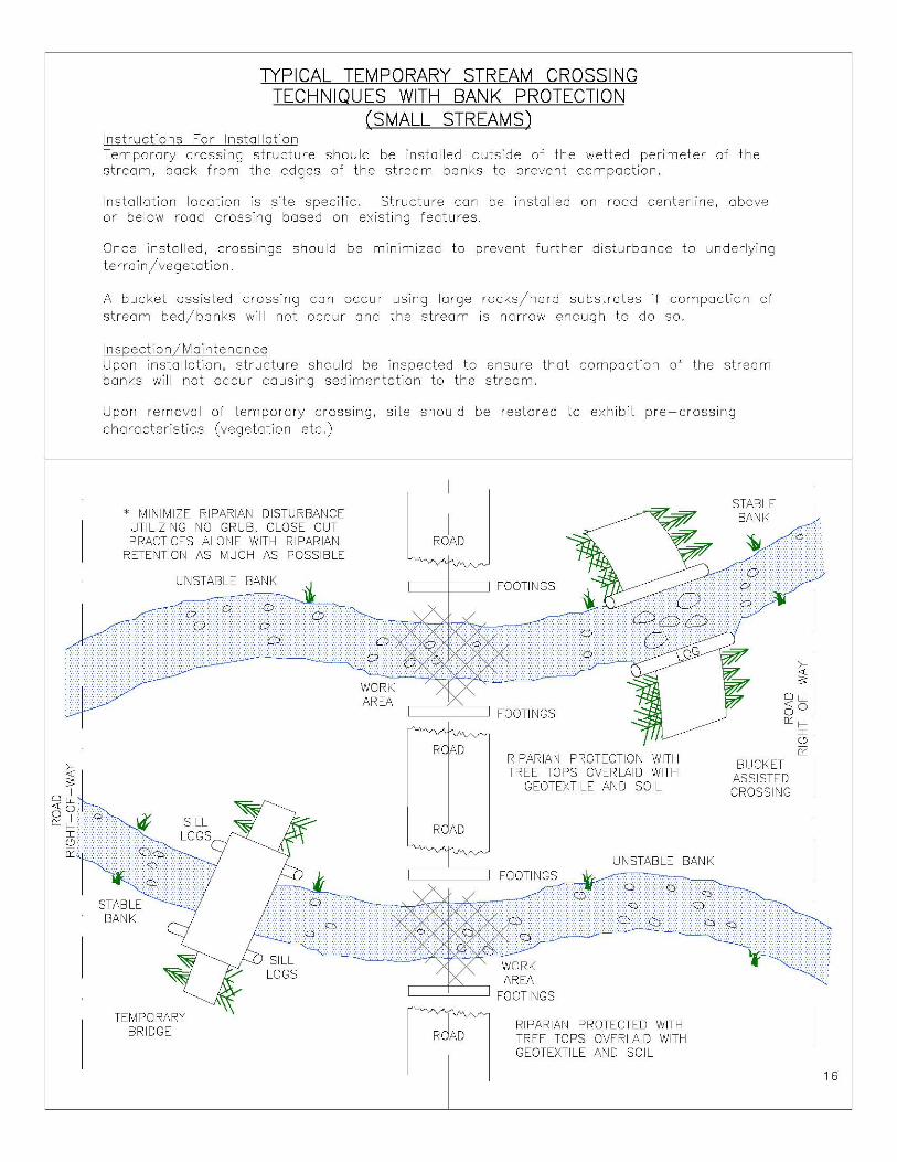
TYPICAL TEMPORARY STREAM CROSSING TECHNIQUES WITH BANK PROTECTION
(SMALL STREAMS) Instructions For Installation Temporary crossing structure should be installed outside of the welted perimeter of the stream, back from the edges of the stream banks to prevent compaction.
Installation location is site specific. Structure con be installed on road centerline, above or below road crossing based on existing features.
Once installed, crossings should be minimized to prevent further disturbance to underlying terrain/vegetation.
A bucket assisted crossing can occur using large rocks/hard substrates if compaction of stream bed/banks will not occur and the stream is narrow enough to do so.
Inspection IMaintena nee Upon installation, structure should be inspected to ensure that compaction of the stream banks will not occur causing sedimentation to the stream.
Upon removal of temporary crossing, site should be restored to exhibit pre-crossing characteristics (vegetation etc.)
* MINIMIZE RIPARIAN DISTURBANCE UTILIZING NO GRUB, CLOSE CUT PRACTICES ALONE WITH RIPARIAN
RETENTION AS MUCH AS POSSIBLE
STABLE BANK
UNSTABLE BANK
TEMPORARY BRIDGE
WORK AREA
I ROAD
CC+=C:::J FOOTINGS
CC= 'c:::J FOOTINGS
R D RIPARIAN PROTECTION WITH TREE TOPS OVERLAID WITH
GEOTEXTILE AND SOIL
STABLE BANK
BUCKET ASSISTED CROSSING
UNSTABLE BANK
CC=CJI FOOTI ~NG;;:Sk--~000820S20S=~~
WORK AREA
CC±:''c:::J FOOTINGS
1"~fC RIPARIAN PROTECTED WITH TREE TOPS OVERLAID WITH GEOTEXTILE AND SOIL
16
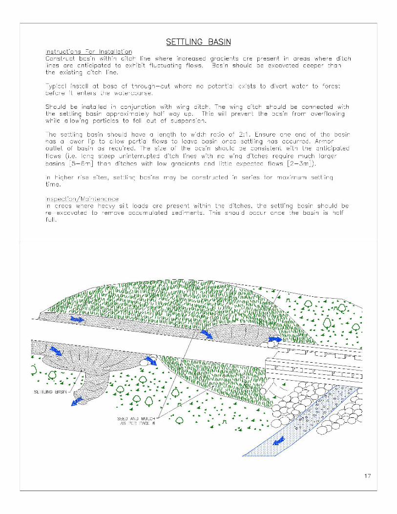
SETILING Instructions For Installation Construct basin within ditch line where increased lines ore anticipated to exhibit fluctuating flows. the existing ditch line.
BASIN
gradients are present in areas where ditch Basin should be excavated deeper than
Typical install at base of through-cut where no potential exists to divert water to forest before it enters the watercourse.
Should be installed in conjunction with wing ditch. The wing ditch should be connected with the settling basin approximately half way up. This will prevent the basin from overflowing while allowing particles to fallout of suspension.
The settling basin should have a length to width ratio of 2: 1. Ensure one end of the basin has a lower lip to allow partial flows to leave basin once settling has occurred. Armor outlet of basin as required. The size of the basin should be consistent with the anticipated flows (i.e. long steep uninterrupted ditch lines with no wing ditches require much larger basins [5-6mJ thon ditches with low gradients ond little expected flows [2-3mJ).
In higher rise sites, settling basins may be constructed in series for maximum settling time.
Inspection IMointeno nee In areas where heavy silt loads are present within the ditches, the settling basin should be re-excovated to remove accumulated sediments. This should occur once the basin is half full.
j··o . .. .. .... !c. ..
SETTLING BASIN
SEED AND MULCH AS PER PAGE 6 "'0
" . " .
•
"
" . . . . . .- . .n
.~
17