Embed Size (px)
Citation preview


1
2468
1012141618202224
2628
30343638
40
42
44
464748
50545658616264
6667686970
Fixed Thick Film Chip Resistors; Rectangular Type RMCFixed Thick Film Chip Resistors; Rectangular Type & Precision RGCFixed Thin Film Chip Resistors; Rectangular Type RNCFixed Thick Film Chip Resistors; Rectangular Type & High Voltage RVCFixed Thick Film Chip Resistors; Rectangular Type & Ultra High Voltage RZCFixed Thick Film Chip Resistors; Rectangular Type & Anti Surge RPCTrimmable Chip Resistors; Rectangular Type FCRFixed Thick Film Chip Resistors; Rectangular Type & Low Ohm RLCFixed Thick Film Chip Resistors; Rectangular Type & Low Ohm RLSMetal-Plate Chip Resistors; Low Ohm RLP, MLPFixed Thick Film Chip Resistors; Rectangular Type & Low Ohm RCCFixed Thick Film Chip Resistors; Rectangular Type & High Ohm RHC
Fixed Chip Resistor Networks; Rectangular Type RACFixed Chip Resistor Networks; Rectangular Type RAC168U
Chip Fuses ; Rectangular Type FCC, FHCChip Fuses ; Rectangular Type/Low-Ohm Fast Acting FMCChip Fuses ; Rectangular Type/In-rush Withstand FSCChip Fuses ; Rectangular Type/Low-ratio Fusing FLC
KAMAYA OHM
NEW
NEW
NEW
General Purpose
High Voltage
SurgeTrimmableSensing
Chip Networks
Circuit Protection
Chi
p R
esis
tors
Chi
p R
esis
tor
Net
wor
ksC
hip
Fus
es
Chip Fusible Resistors ; Rectangular Type FRC
Chip Attenuators RAC101A
Linear Positive T-C Chip Thermistors; Rectangular Type LTC
Fixed Fusible Resistors FRNFixed High Voltage Resistors RNVFixed Conductive Path Resistors RC1/2UFixed Carbon Composition Resistors RCJumper Wires JWFixed High Voltage Resistors; Precision RH
Packaging for Leaded Resistors
Recommended Land PatternRecommended Soldering ConditionPackaging for Surface Mount Devices
Product MarkingKamaya Shipping LabelsStandard Resistance Values and SymbolsGlossaryTerm Explanation
Circuit Protection
High Frequency
Temperature Compensation
Circuit ProtectionHigh VoltagePulse
JumpersHigh Voltage
Chi
p F
usib
leR
esis
tors
Chi
p At
tenu
ator
sLP
T C
hip
The
rmis
tors
Info
rmat
ion
Lead
ed R
esist
ors
Chip Resistors
Chip Resistor Networks
Chip Fuses
Chip Fusible Resistors
Chip Attenuators
Chip Thermistors
Information
Leaded Resistors
103RMC 1/10
Style
K F TP
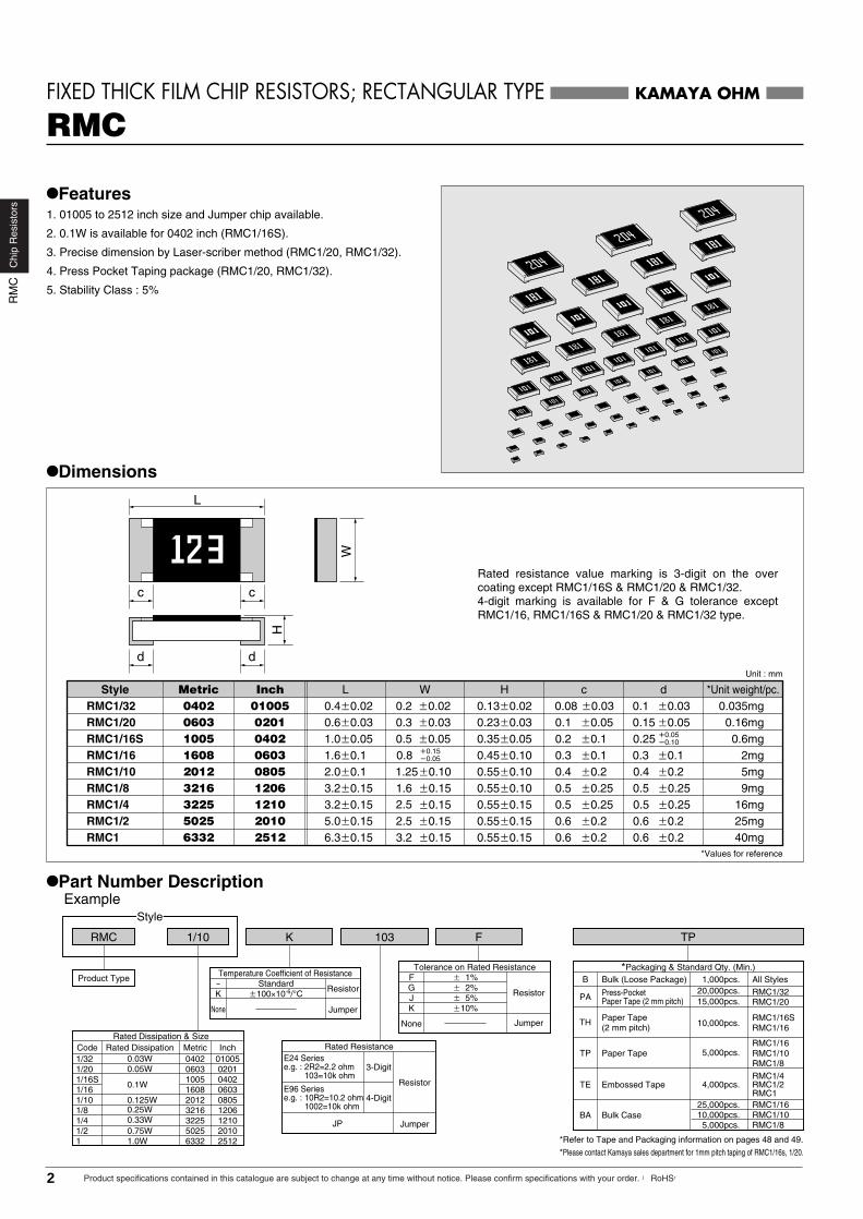
Rated resistance value marking is 3-digit on the over coating except RMC1/16S & RMC1/20 & RMC1/32.4-digit marking is available for F & G tolerance except RMC1/16, RMC1/16S & RMC1/20 & RMC1/32 type.
Example
Product Type
Rated Dissipation & SizeCode
1/16S
Metric
1005160820123216322550256332
1/20 0603
Inch
0402060308051206121020102512
02010.05W1/32 0402 010050.03W
1/160.1W
1/10 0.125W1/8 0.25W
0.33W1/41/2 0.75W1 1.0W
Rated Dissipation
Tolerance on Rated ResistanceF
None
� 1%G
Resistor
Jumper
� 2%J � 5%K �10%
*Packaging & Standard Qty. (Min.)Bulk (Loose Package)B All Styles
*Refer to Tape and Packaging information on pages 48 and 49.
*Please contact Kamaya sales department for 1mm pitch taping of RMC1/16s, 1/20.
Temperature Coefficient of Resistance–
None
StandardK
Resistor
Jumper
�100×10-6/°C
Rated Resistance
JP
4-DigitE96 Seriese.g. : 10R2=10.2 ohm 1002=10k ohm
3-DigitE24 Seriese.g. : 2R2=2.2 ohm 103=10k ohm
Resistor
Jumper
PA Press-PocketPaper Tape (2 mm pitch)
TH Paper Tape(2 mm pitch)
RMC1/16SRMC1/16
Paper TapeTPRMC1/16RMC1/10RMC1/8
Embossed TapeTERMC1/4RMC1/2RMC1
Bulk CaseBARMC1/16RMC1/10RMC1/8
1,000pcs.
10,000pcs.
5,000pcs.
4,000pcs.
25,000pcs.10,000pcs.5,000pcs.
KAMAYA OHM
•Features1. 01005 to 2512 inch size and Jumper chip available.
2. 0.1W is available for 0402 inch (RMC1/16S).
3. Precise dimension by Laser-scriber method (RMC1/20, RMC1/32).
4. Press Pocket Taping package (RMC1/20, RMC1/32).
5. Stability Class : 5%
RMC
•Dimensions
•Part Number Description
RMC1 �0.15 6.3�0.15
Unit : mm
*Values for reference
0.55�0.15 0.6 �0.2 �0.2 40mgRMC1/2 �0.15 5.0�0.15 0.55�0.15 0.6 �0.2 �0.2 25mgRMC1/4 �0.15 3.2�0.15 0.55�0.15 0.5 �0.25 �0.25 16mgRMC1/8 �0.15 3.2�0.15 0.55�0.10 0.5 �0.25 �0.25 9mgRMC1/10 �0.102.0�0.1 0.55�0.10 0.4 �0.2 �0.2 5mgRMC1/16 1.6�0.1 0.45�0.10 0.3 �0.1 �0.1 2mgRMC1/16S 0.5 �0.05 1.0�0.051005
160820123216322550256332
0.35�0.05 0.2 �0.1 �0.05�0.10 0.6mg
0.16mg
Style WLMetric
0402060308051206121020102512
Inch H c d *Unit weight/pc.
0.25RMC1/20 0.3 �0.03 0.6�0.030603 0.23�0.03 0.1 �0.050201
�0.15�0.050.8
FIXED THICK FILM CHIP RESISTORS; RECTANGULAR TYPE
L
c c
W
d d
1.251.62.52.53.2
0.3
�0.050.150.035mgRMC1/32 0.2 �0.02 0.4�0.020402 0.13�0.02 0.08 �0.0301005 �0.030.1
0.40.50.50.60.6
H
RMC1/3220,000pcs.RMC1/2015,000pcs.
2 Product specifications contained in this catalogue are subject to change at any time without notice. Please confirm specifications with your order. 【RoHS】
Chi
pR
esis
tors
RM
C

Description Requirements
No breakdown or flashoverR≥1G ohm
∆R≤±(1%+0.05 ohm)No visible damage, legible marking
∆R≤±(5%+0.1 ohm) No visible damage
∆R≤±(5%+0.1 ohm) No visible damage
See Ratings Table
In accordance with Clause 4.17.4.5
∆R≤±(1%+0.05 ohm)
∆R≤±(1%+0.05 ohm) No visible damage
∆R≤±(5%+0.1 ohm) No visible damage, legible marking
∆R≤±(5%+0.1 ohm) No visible damage
No visible damage
∆R≤±(1%+0.05 ohm)
Test MethodsClause 4.7
Clause 4.13
Clause 4.23
Clause 4.25.1
Clause 4.8
Clause 4.17Clause 4.18
Clause 4.19
Clause 4.24
Clause 4.25.3
Clause 4.32Clause 4.33
RMC1/32,1/20 50Va.c.,60sRMC1/16S,1/16 100Va.c.,60sRMC1/10~1 500Va.c.,60s
The applied voltage shall be 2.5 times of the rated voltage or twiceof the limiting element voltage, whichever is the less severe, 2s.
Dry/Damp heat (12+12h cycle), first cycle./Cold/Damp heat (12+12h cycle), remaining cycle./ D.C.Load.
Rated voltage, 1.5h"ON", 0.5h"OFF", 70°C, 1,000h
+20°C/–55°C/+20°C/+125°C/+20°C : RMC1/32, 1/20+20°C/–55°C/+20°C/+155°C/+20°C : RMC1/16S~1
235°C, 2sAfter immersion into the flux, the immersion into soldershall be carried out in Solder bath at 260°C for 5s.5 cycles between −55°C and +125°C : RMC1/32, 1/205 cycles between −55°C and +155°C : RMC1/16S~1
40°C, 95%R.H., 56 days, test a) and b) of Clause 4.24.2.1
125°C, no-load, 1,000h. : RMC1/32, 1/20155°C, no-load, 1,000h. : RMC1/16S~15N, 10s ( RMC1/20 = 3N , RMC1/32 = 2N )RMC1/32~1/4 Amount of bend : 3 mmRMC1/2, 1 Amount of bend : 1 mm
Bend strength of theface plating
Voltage proof
Overload
Climatic sequence
Endurance at 70°C
Variation of resistancewith temperature
SolderabilityResistance tosoldering heatRapid change oftemperature
Damp test, steady state
Endurance at the uppercategory temperatureAdhesion
Perc
enta
ge o
f the
rate
d di
ssip
atio
n(c
urre
nt)(%
)
Area of recommended operation
Note1. E24 series is available , E96 series is available for tolerance"F"(1%)Note2. Rated Voltage = (Rated Dissipation)×(Rated Resistance). (d.c. or a.c. r.m.s. Voltage)Note3. Limiting Element Voltage can only be applied to resistors when the resistance value is equal to or higher than the critical resistance value.Note4. Critical Resistance Value is the resistance value at which the rated voltage is equal to the limiting element voltage.Note5. Jumper : Resistance value is less than 50m ohm.
•Derating CurveThe derated values of dissipation for temperatures in excess of 70°C shall be indicated by the following Curve.(For Jumpers the load current shall be derated according to the Derating Curve )
KAMAYA OHM
RMC
•Ratings
•Climatic Category55/125/56 : RMC1/32, 1/2055/155/56 : RMC1/16S, 1/16, 1/10, 1/8, 1/4, 1/2, 1
RMC1/16S, 1/16, 1/10, 1/8, 1/4, 1/2, 1–55°C
+155°C56 days
RMC1/32, 1/20–55°C
+125°C56 days
Lower Category TemperatureUpper Category TemperatureDuration of the Damp heat, Steady-State Test
Ambient Temperature (°C)
100
0�55 125 15570
RMC1/16S, 1/16, 1/10, 1/8, 1/4, 1/2, 1
RMC1/32, 1/20
FIXED THICK FILM CHIP RESISTORS; RECTANGULAR TYPE
•Performance Characteristics JIS C 5201-1 : 1998
1~9.76
10~1M
0.33~0.91
1.1M~22M
1~9.76
10~1M
0.33~0.91
11M~24M1.02M~10M
1~9.76
10~1M
0.22~0.91
11M~22M
1.1M~22M
1.02M~10M
1~9.76
10~1M
0.2~0.91
RMC1/16S
RMC1/20
RMC1/16
RMC1/10
RMC1/8
RMC1/4
RMC1/2
RMC1
0.05(1.0A)
0.1(1.0A)
0.125(2.0A)
0.25(2.0A)
0.33(2.0A)
0.75(2.0A)
1.0(2.0A)
50
100
500
-55~+155
-55~+1250.47~0.91
0.47~0.91
0.27~0.91
1~9.76
1~9.76
1~9.76
1~9.76
10~97.6100~1M
4.7~9.110~91
100~1M
10~2.2M
2.21M~10M
1.1M~10M
1.02M~10M
11M~22M
11M~22M
+600~-200+1000~+300
+500~-200
+500~-200
+500~-200
+500~-200
+1,000~+300
+1,000~+300
+1,000~+300
±300
±200
±200
±200
±200
±200
±200
±200
±100
±100
±100
±200
±200
±100
+500~-200+1,000~+300
±200
±200
±100
+500~-200+1,000~+300
±200
±200±100
+500~-200+1,000~+300
±200
±200±100
---
±300+600~-200
±200
---
---
----
---
-
---
-
---
-
--
--
-
--
-
-
K
K
K
K
K
K
K
JF, J
F, J
F, G, J
JF, JG, J
FF, G, J
KF, G, J
G, JFJK
F, G, JG, J
FF, G, J
JK
F, G, JG, J
FF, G, J
JK
F, JG, J
FF, G, J
JK
F, JG, J
FJK
F, JG, J
FJ
25
15
50
150
200
0603(0201)
RMC1/32 0.03(0.5A)
0402(01005)
1005(0402)
1608(0603)
2012(0805)
3216(1206)
3225(1210)
5025(2010)
6332(2512)
10~1M
StyleRated Dissipation
at 70°CW
Rated Resistance Range IsolationVoltage
V
CategoryTemperature
Range°C
1� 10� 100� 1M� 10M�
Temperature Coefficientof Resistance
10-6/°CCode
Toleranceon Rated
Resistance
LimitingElementVoltage
V
SizeMetric(Inch)
10~10M
3Product specifications contained in this catalogue are subject to change at any time without notice. Please confirm specifications with your order. 【RoHS】
Chi
pR
esis
tors
RM
C
RG
CC
hip
Res
isto
rs
Product specifications contained in this catalogue are subject to change at any time without notice. Please confirm specifications with your order. 【RoHS】4
TH
B All Styles
TP
BA
D TPRGC 1/16
Product Type
Style
C 473
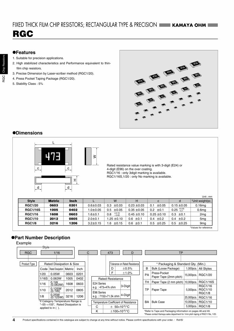
Rated resistance value marking is with 3-digit (E24) or 4-digit (E96) on the over coating.RGC1/16 : only 3digit marking is available.RGC1/16S,1/20 : only No marking is available.
Rated Dissipation & Size
Code Rated Dissipation Metric
1/16S 0.063W 1005
1608
2012
3216
Inch
04021/20 0.05W 0603 0201
0603
0805
1206
1/16
1/10
1/8
0.125W(0.1W)0.25W(0.125W)
Temperature Coefficient of ResistanceC � 50×10-6/°CK �100×10-6/°C
Tolerance on Rated ResistanceD �0.5%F �1.0%
RGC1/16S
RGC1/16RGC1/10RGC1/8
RGC1/16RGC1/10RGC1/8
Rated Resistance
4-DigitE96 Seriese.g. : 7152=71.5k ohm
3-DigitE24 Seriese.g. : 473=47k ohm
* Packaging & Standard Qty. (Min.)Bulk (Loose Package)
Paper Tape (2 mm pitch)
Paper Tape
Bulk Case
1,000pcs.
PA RGC1/20Press-PocketPaper Tape (2mm pitch)
15,000pcs.
10,000pcs.
5,000pcs.
25,000pcs.10,000pcs.
5,000pcs.
*Refer to Tape and Packaging information on pages 48 and 49.
•Part Number DescriptionExample
KAMAYA OHMFIXED THICK FILM CHIP RESISTORS; RECTANGULAR TYPE & PRECISION
•Features1. Suitable for precision applications.
2. High stabilized characteristics and Performance equivalent to thin-
film chip resistors.
3. Precise Dimension by Laser-scriber method (RGC1/20).
4. Press Pocket Taping Package (RGC1/20).
5. Stability Class : 5%
RGC
•Dimensions
Unit : mm
*Values for reference
RGC1/8 �0.15 3.2�0.15 �0.1 �0.25 �0.25 9mg5mg2mg
0.6mg
RGC1/10 1.25 �0.102.0�0.1 �0.1 �0.2 �0.2RGC1/16 1.6�0.1 0.45 �0.10 0.25 �0.10 �0.1
�0.05RGC1/16S �0.05 1.0�0.051005
160820123216
0.35 �0.05 �0.1 �0.05�0.1
Style WLMetric
0402060308051206
Inch H c d *Unit weight/pc.
0.25�0.15�0.050.8
W
d d
L
c c
H
0.5
1.60.60.6
0.20.16mgRGC1/20 �0.03 0.6�0.030603 0.23 �0.03 �0.050201 0.150.3 0.1
0.40.5
0.30.40.5
NEW
*Please contact Kamaya sales department for 1mm pitch taping of RGC1/16s, 1/20.
0.1W(0.063W)
�If Category Temperature Range is "–55~+155", Rated Dissipation is applied to in ( ).

Perc
enta
ge o
f the
rate
d di
ssip
atio
n(%
)
KAMAYA OHM
FIXED THICK FILM CHIP RESISTORS; RECTANGULAR TYPE & PRECISION RGC
•Ratings
Ambient Temperature (°C)
100
0�55 125 15570
•Derating CurveThe derated values of dissipation for temperatures in excess of 70°Cshall be indicated by the following Curve.
�1 If Category Temperature Range is "–55~+155", Rated Dissipation is applied to in ( ).
Description Requirements
No breakdown or flashoverR≥1G ohm
Test Methods
Clause 4.7
Clause 4.13
Clause 4.23
Clause 4.25.1
Clause 4.17
Clause 4.18
Clause 4.19
Clause 4.32
Clause 4.33
RGC1/20 50Va.c.,60sRGC1/16S, 1/16, 1/10, 1/8 100Va.c.,60s
The applied voltage shall be 2.5 times of the rated voltage or twice of the limiting element voltage, whichever is the less severe, 2s.
Dry/Damp heat (12+12h cycle), first cycle./Cold/Damp heat (12+12h cycle), remainingcycle. /D.C.Load.
Rated voltage, 1.5h"ON", 0.5h"OFF", 70°C, 1,000h.
235°C, 2s
After immersion into the flux, the immersion into solder shall be carried out in Solder bath at 260°C for 5s.
5 cycles between −55°C and +125°C �2(+155°C).
5N, 10s (RGC1/20 : 3N)
Amount of bend : 3 mm
Voltage proof
Overload
Climatic sequence
Endurance at 70°C
Solderability
Resistance to soldering heat
Rapid change of temperature
Adhesion
Bend strength of the face plating
•Climatic Category55/125/56 �2(55/155/56)
Lower Category Temperature −55°C �2(–55°C)Upper Category Temperature +125°C �2(+155°C)Duration of the Damp heat,Steady-State Test 56 days �2(56 days)
∆R≤±(1%+0.05 ohm)No visible damage, legible marking
In accordance with Clause 4.17.4.5
∆R≤±(1%+0.05 ohm)
∆R≤±(1%+0.05 ohm) No visible damage
∆R≤±(5%+0.1 ohm) No visible damage
∆R≤±(5%+0.1 ohm) No visible damage, legible marking
∆R≤±(5%+0.1 ohm) No visible damage
∆R≤±(5%+0.1 ohm) No visible damage
No visible damage
∆R≤±(1%+0.05 ohm)
Clause 4.8 Measuring temperature : +20°C/+125°C �2(+155°C) /+20°CVariation of resistance with temperature See Ratings Table
Clause 4.24 40°C, 95%R.H., 56 days, test a) and b) of Clause 4.24.2.1Damp test, steady state
Clause 4.25.3 125°C �2(155°C), no-load, 1,000h.Endurance at the upper category temperature
StyleSize
Metric(Inch)
Limiting ElementVoltage
V
�100� 50
�100
�100
� 50�100
� 50
� 50
K
K
K
C
C�100� 50
KC
K
C
C
Temperature Coefficientof ResistanceTolerance on
Rated Resistance
Rated Resistance Range10� 100� 1k� 1M�
IsolationVoltage
V
Category TemperatureRange
°C
50
150
200
D(�0.5%)F(�1%)
D(�0.5%)
F(�1%)
D(�0.5%)F(�1%)
F(�1%)D (�0.5%), F (�1%)F(�1%)
D (�0.5%), F (�1%)
Rated Dissipationat 70°C
W
0.1�1(0.063)
0.125�1(0.1)
0.063
0.25�1(0.125)
RGC1/16S
RGC1/16
RGC1/10
RGC1/8
100
500
�55��125�1(�55��155)
�55��155
25 50 �55��125
10-6/°cCode
10�97.6100�1M
51�976
1k�1M
1.02M�3.3M3.3�9.76
10�97.6100�1M
1.02M�3.3M3.3�9.76
3.3�9.7610�4.7M
10�3.3M
�2
�2 ( ) on Derating Curue, Climatic Category, and Test Methods will be applied, when Upper Category Temperature is +155°C.
1005(0402)
0.05RGC1/200603
(0201)
1608(0603)
2012(0805)
3216(1206)
Area of recommended operation
Note1. E24, E96 are avaialable for "F"(1%) and "D"(0.5%)Note2. Rated Voltage = (Rated Dissipation)×(Rated Resistance). (d.c. or a.c. r.m.s. Voltage)Note3. Limiting Element Voltage can only be applied to resistors when the resistance value is equal to or higher than the critical resistance value.Note4. Critical Resistance Value is the resistance value at which the rated voltage is equal to the limiting element voltage.
•Performance Characteristics JIS C 5201-1 : 1998
5Product specifications contained in this catalogue are subject to change at any time without notice. Please confirm specifications with your order. 【RoHS】
Chi
pR
esis
tors
RG
C

1002RNC 32
Product Type
Style
E B TP
FIXED THIN FILM CHIP RESISTORS; RECTANGULAR TYPE
•Features1. Suitable for high precision, higher stability and reliability applications
compared to thick-film chip resistors.
2. Contribute to the reduction of fine adjustment, high accuracy and
stability of circuit.
3. Stability Class : 1%
RNC
Rated resistance value is maked with 3-digit (E24) or4-digit (E96) on the over coating.
•Dimensions
•Part Number DescriptionExample
SizeCode Metric20 201232 3216
Temperature Coefficient of ResistanceE �25×10-6/°C
Tolerance on Rated Resistance BCD
�0.1%�0.25%�0.5%
* Packaging & Standard Qty. (Min.)Bulk (Loose Package)BPaper Tape
1,000pcs.5,000pcs.TP
*Refer to Tape and Packaging information on pages 48 and 49.
Rated Resistance
4-Digit
3-DigitE24 Seriese.g. : 103=10k ohm
E96 Seriese.g. : 10R2=10.2 ohm
1002=10k ohm
Inch08051206
KAMAYA OHM
RNC32 3.1�0.1 0.6�0.1 0.45�0.20RNC20 2.0�0.15 0.6�0.1 �0.22012
3216
Style WLMetric08051206
Inch H c
9mg5mg�0.10
�0.051.25�0.10�0.051.55
d�0.2�0.10.3�0.2�0.10.3
W
d d
L
c c
H
0.4
Unit : mm
*Values for reference
*Unit weight/pc.
6 Product specifications contained in this catalogue are subject to change at any time without notice. Please confirm specifications with your order. 【RoHS】
Chi
pR
esis
tors
RN
C

100
0-55 12570
•Ratings
Note1. Rated Voltage = (Rated Dissipation)×(Rated Resistance). (d.c. or a.c. r.m.s. Voltage)Note2. Limiting Element Voltage can only be applied to resistors when the resistance value
is equal to or higher than the critical resistance value.Note3. Critical Resistance Value is the resistance value at which the rated voltage is equal to the limiting element voltage.
•Derating CurveThe derated values of dissipation for temperatures in excess of 70°Cshall be indicated by the following Curve.
•Climatic Category55/125/56
Lower Category Temperature −55°CUpper Category Temperature +125°CDuration of the Damp heat,Steady-State Test 56 days
Ambient Temperature (°C)
Perc
enta
ge o
f the
rate
d di
ssip
atio
n(%
)
Area of recommended operation
FIXED THIN FILM CHIP RESISTORS; RECTANGULAR TYPE RNC
KAMAYA OHM
RNC20 0.1
0.125RNC32 150
75
�25 E96E24
100 �55��125
•Performance Characteristics JIS C 5201-1 : 1998
Description Requirements Test Methods
Clause 4.7
Clause 4.13
Clause 4.23
Clause 4.25.1
Clause 4.8
Clause 4.17
Clause 4.18
Clause 4.19
Clause 4.25.3
Clause 4.32
Clause 4.33
100Va.c.,60s
The applied voltage shall be 2.5 times of the rated voltage or twice of the limiting element voltage, whichever is the less severe, 2s.
Dry/Damp heat(12+12h cycle), first cycle./Cold/Damp heat(12+12h cycle), remainingcycle./ D.C.Load.
Rated voltage, 1.5h"ON", 0.5h"OFF", 70°C, 1,000h.
Measuring temperature : +20°C/+125°C/+20°C
235°C, 2s
After immersion into the flux, the immersion into solder shall be carried out in Solder bath at 260°C for 5s.
5 cycles between −55°C and +125°C.
125°C, no-load, 1,000h.
5N, 10s
Amount of bend : 3 mm
Voltage proof
Overload
Climatic sequence
Endurance at 70°C
Variation of resistancewith temperature
Solderability
Resistance tosoldering heat
Rapid change oftemperature
Damp test, steady state
Endurance at the upper category temperature
Adhesion
Bend strength ofthe face plating
No breakdown or flashoverR≥1G ohm
See Ratings Table
∆R≤±(0.25%+0.05 ohm)No visible damage, legible marking
In accordance with Clause 4.17.4.5
∆R≤±(0.25%+0.05 ohm)
∆R≤±(0.25%+0.05 ohm) No visible damage
∆R≤±(1%+0.05 ohm)No visible damage
∆R≤±(1%+0.05 ohm)No visible damage, legible marking
∆R≤±(1%+0.05 ohm) No visible damage, legible marking
∆R≤±(1%+0.05 ohm) No visible damage
No visible damage
∆R≤±(0.25%+0.05 ohm)
Clause 4.24 40°C, 95%R.H., 56 days, test a) and b)of Clause 4.24.2.1
3216(1206)
2012(0805)
StyleRated Dissipation
at 70°CW
Limiting ElementVoltage
V
Temperature Coefficientof Resistance
10-6/°C
Preferred NumberSeries forResistors
IsolationVoltage
V
Category TemperatureRange
°C
Size
(Inch)Metric
100��130k�
10��130k�
100��180k�
10��180k�
B (�0.1%)
C (�0.25%)D (�0.5%)
B (�0.1%)
C (�0.25%)D (�0.5%)
Tolerance onRated Resistance
Rated ResistanceRange
7Product specifications contained in this catalogue are subject to change at any time without notice. Please confirm specifications with your order. 【RoHS】
Chi
pR
esis
tors
RN
C

RVC 32
Product Type
Style
K 475 F TP
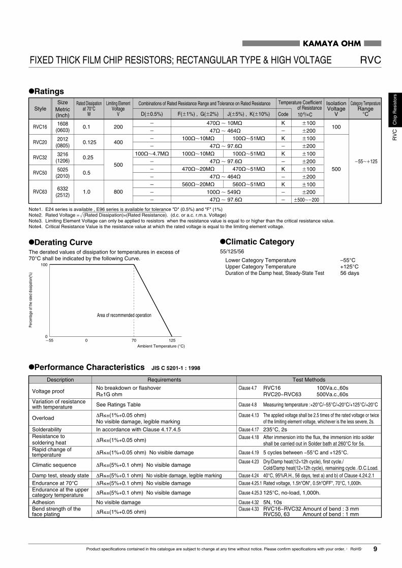
•Features1. Higher Limiting Element Voltage compared with RMC (general use)
2. Stability Class : 5%
•Dimensions
Rated resistance is marked with 3-digit (E24)or 4-digit (E96) on the over coating.RVC16 : only 3digit marking is available.
•Part Number DescriptionExample
Tolerance on Rated Resistance
F � 1%D � 0.5%
G � 2%J � 5%K �10%
* Packaging & Standard Qty. (Min.)
Bulk (Loose Package)
RVC50RVC63
B
Paper TapeTPRVC16RVC20RVC32
Embossed TapeTE
*Refer to Tape and Packaging information on pages 48 and 49.
All Styles1,000pcs.
5,000pcs.
4,000pcs.
SizeCode Metric16 1608
32 321650 5025
20 2012
63 6332
Inch0603
12062010
0805
2512 Temperature Coefficient of Resistance
K �100×10-6/°C– Standard
Rated Resistance
4-DigitE96 Seriese.g. : 7154=7.15M ohm
3-DigitE24 Seriese.g. : 475=4.7M ohm
KAMAYA OHM
RVC63 �0.156.3�0.15 0.55�0.15 �0.2 40mgRVC50 �0.155.0�0.15 0.55�0.15 �0.2 25mgRVC32 3.2�0.15 0.55�0.10 �0.25 9mgRVC20 1.25�0.102.0�0.1 2012
321650256332
0.55�0.10 5mg2mg
Style WLMetric
0805120620102512
Inch H c dRVC16
1.6 �0.15
1.6�0.1 1608 0.45�0.100603 �0.15�0.050.8
FIXED THICK FILM CHIP RESISTORS; RECTANGULAR TYPE & HIGH VOLTAGE
L
c c
W
d d
2.53.2
0.5�0.20.4�0.10.3
0.60.6�0.2
�0.2�0.250.5�0.20.4�0.10.3
0.60.6
H
RVC
Unit : mm
*Values for reference
*Unit weight/pc.
8 Product specifications contained in this catalogue are subject to change at any time without notice. Please confirm specifications with your order. 【RoHS】
Chi
pR
esis
tors
RV
C
FIXED THICK FILM CHIP RESISTORS; RECTANGULAR TYPE & HIGH VOLTAGE RVC
•Ratings
Note1. E24 series is available , E96 series is available for tolerance "D" (0.5%) and "F" (1%) Note2. Rated Voltage = (Rated Dissipation)×(Rated Resistance). (d.c. or a.c. r.m.s. Voltage)Note3. Limiting Element Voltage can only be applied to resistors when the resistance value is equal to or higher than the critical resistance value.Note4. Critical Resistance Value is the resistance value at which the rated voltage is equal to the limiting element voltage.
Description Requirements
No breakdown or flashoverR≥1G ohm
∆R≤±(1%+0.05 ohm)No visible damage, legible marking
∆R≤±(5%+0.1 ohm) No visible damage
∆R≤±(5%+0.1 ohm) No visible damage
See Ratings Table
In accordance with Clause 4.17.4.5
∆R≤±(1%+0.05 ohm)
∆R≤±(1%+0.05 ohm) No visible damage
∆R≤±(5%+0.1 ohm) No visible damage, legible marking
∆R≤±(5%+0.1 ohm) No visible damage
No visible damage
∆R≤±(1%+0.05 ohm)
Test Methods
Clause 4.7
Clause 4.13
Clause 4.23
Clause 4.25.1
Clause 4.8
Clause 4.17Clause 4.18
Clause 4.19
Clause 4.24
Clause 4.25.3
Clause 4.32Clause 4.33
RVC16 100Va.c.,60sRVC20~RVC63 500Va.c.,60s
The applied voltage shall be 2.5 times of the rated voltage or twiceof the limiting element voltage, whichever is the less severe, 2s.
Dry/Damp heat(12+12h cycle), first cycle./Cold/Damp heat(12+12h cycle), remaining cycle. /D.C.Load.
Rated voltage, 1.5h"ON", 0.5h"OFF", 70°C, 1,000h.
Measuring temperature :+20°C/–55°C/+20°C/+125°C/+20°C
235°C, 2sAfter immersion into the flux, the immersion into soldershall be carried out in Solder bath at 260°C for 5s.
5 cycles between −55°C and +125°C.
40°C, 95%R.H., 56 days, test a) and b) of Clause 4.24.2.1
125°C, no-load, 1,000h.
5N, 10sRVC16~RVC32 Amount of bend : 3 mmRVC50, 63 Amount of bend : 1 mm
Bend strength of theface plating
Voltage proof
Overload
Climatic sequence
Endurance at 70°C
Variation of resistancewith temperature
SolderabilityResistance tosoldering heatRapid change oftemperature
Damp test, steady state
Endurance at the uppercategory temperatureAdhesion
•Derating CurveThe derated values of dissipation for temperatures in excess of70°C shall be indicated by the following Curve.
•Climatic Category55/125/56
Lower Category Temperature –55°CUpper Category Temperature +125°CDuration of the Damp heat, Steady-State Test 56 days
KAMAYA OHM
RVC16
RVC20
RVC32
RVC50
RVC63
0.1
0.125
0.25
0.5
1.0
100
0�55 0 12570
200�100�
100��10M�400
500
800
�200�100�200�100�200�100�200�100
�500��200�200
K�
�
�
�
100��4.7M�
�
�
�
�
�
�
�
K�
K�
K�
K
�
�
�
�
100��51M�
100
500�55��125
100��10M�
�
100��51M�
470��20M�
�
470��51M�
560��20M�
�
�
470�
47�
47�
47�
47�
100�
47�
10M�
464�
97.6�
97.6�
464�
549�
97.6�
560��51M�
1608(0603)
2012(0805)
3216(1206)
5025(2010)
6332(2512)
StyleCombinations of Rated Resistance Range and Tolerance on Rated Resistance
F(�1%) , G(�2%)D(�0.5%) J(�5%) , K(�10%)
Rated Dissipationat 70°C
W
Limiting ElementVoltage
V
Temperature Coefficientof Resistance
IsolationVoltage
V
Category TemperatureRange
°C10-6/∞CCode
Perc
enta
ge o
f the
rate
d di
ssip
atio
n(%
)
Area of recommended operation
Ambient Temperature (°C)
Size
(Inch)Metric
•Performance Characteristics JIS C 5201-1 : 1998
9Product specifications contained in this catalogue are subject to change at any time without notice. Please confirm specifications with your order. 【RoHS】
Chi
pR
esis
tors
RV
C

KAMAYA OHM
•Features1. Endurance in the rushing into voltage of 3,000V.
Note:3,000V, 1sec "On", 9sec"off" ,100,000 times, Room temperature.
2. Higher Limiting Element Voltage than RVC series.
3. Stability Class: 5%
•Dimensions
•Part Number DescriptionExample
Standard―
Bulk (Loose Package)B
* Packaging & Standard Qty. (Min.)
Paper Tape
1,000pcs.
4,000pcs.TE
*Refer to Tape and Packaging information on pages 48 and 49.
RZC63 3.2�0.156.3�0.15
Unit : mm
*Values for reference
0.55�0.15 0.6�0.2 0.6�0.2RZC50 2.5�0.155.0�0.15 0.55�0.15 0.5�0.2 0.6�0.25025
6332
Style WLMetric20102512
Inch H c d
40mg25mg
*Unit/weight/pc.
Tolerance on Rated ResistanceRated Resistance± 5%J±10%K±20%M
e.g.:105=1.0M ohm 475=4.7M ohm 166=16M ohm
W
d d
L
c c
H
Rated resistace is marked with 3-digit(E24) on the over coating.
RZC 50
Product Type
Style
475
Temperature Coefficient of Resistance
J TE
FIXED THICK FILM CHIP RESISTORS;RECTANGULAR TYPE & ULTRA HIGH VOLTAGE
RZC
SizeCode Metric50 502563 6332
Inch20102512
All Styles
All Styles
10 Product specifications contained in this catalogue are subject to change at any time without notice. Please confirm specifications with your order. 【RoHS】
Chi
pR
esis
tors
RZ
C

KAMAYA OHM
•Ratings
RZC50
1.0RZC63
Style
2000
1500
Anti-RushVoltage
CharactoristicsV
Temperature Coefficientof Resistance
10-6/°C
3000 �200 E24
Tolerance onRated Resistance
Rated ResistanceRange
Preferred NumberSeries forResistors
IsolationVoltage
V
500
Category TemperatureRange
°C
�55~+125
Ambient Temperature (°C)
100
0�55 12570
•Derating CurveThe derated values of dissipation for temperatures in excess of 70°Cshall be indicated by the following Curve.
Note1. Rated Voltage = (Rated Dissipation)×(Rated Resistance). (d.c. or a.c. r.m.s. Voltage)Note2. Limiting Element Voltage can only be applied to resistors, when the resistance values is equal to or higher than the critical resistance value.Note3. Anti-Rush Voltage Charactoristics : 3,000V, 1sec "On", 9sec"off" ,100,000 times, Room temperature.
Description Requirements
Voltage proof
Overload
Climatic sequence
Endurance at 70°C
Variation of resistancewith temperature
Solderability
Resistance tosoldering heat
Rapid change oftemperature
Damp test, steady state
Endurance at the upper category temperature
Adhesion
Bend strength ofthe face plating
No breakdown or flashoverR≥1G ohm
See Ratings Table
∆R≤±(1%+0.05 ohm)No visible damage, legible marking
In accordance with Clause 4.17.4.5
∆R≤±(1%+0.05 ohm)
∆R≤±(1%+0.05 ohm) No visible damage
∆R≤±(5%+0.1 ohm)No visible damage
∆R≤±(5%+0.1 ohm)No visible damage, legible marking
∆R≤±(5%+0.1 ohm) No visible damage
∆R≤±(5%+0.1 ohm) No visible damage
No visible damage
∆R≤±(1%+0.05 ohm)
6332(2512)
5025(2010) 0.5 J(�5%)
K(�10%)
M(�20%)
FIXED THICK FILM CHIP RESISTORS;RECTANGULAR TYPE & ULTRA HIGH VOLTAGE RZC
Rated Dissipationat 70°C
W
Limiting ElementVoltage
V
Size
(Inch)Metric
•Climatic Category55/125/56
Lower Category Temperature −55°CUpper Category Temperature +125°CDuration of the Damp heat,Steady-State Test 56 days
Perc
enta
ge o
f the
rate
d di
ssip
atio
n(%
)
Area of recommended operation
Test Methods
Clause 4.7
Clause 4.13
Clause 4.23
Clause 4.25.1
Clause 4.8
Clause 4.13
Clause 4.18
Clause 4.19
Clause 4.25.3
Clause 4.32
Clause 4.33
500Va.c.,60s
The applied voltage shall be 2.5 times of the rated voltage or twice of the limiting element voltage, whichever is the less severe, 2s.
Dry/Damp heat(12+12h cycle), first cycle./Cold/Damp heat(12+12h cycle), remainingcycle./ D.C.Load.
Rated voltage, 1.5h"ON", 0.5h"OFF", 70°C, 1,000h.
Measuring temperature : +20°C/−55°C/+20°C/+125°C/+20°C
235°C, 2s
After immersion into the flux, the immersion into solder shall be carried out in Solder bath at 260°C for 5s.
5 cycles between −55°C and +125°C.
125°C, no-load, 1,000h.
5N, 10s
Amount of bend : 1 mm
Clause 4.24 40°C, 95%R.H., 56 days, test a) and b)of Clause 4.24.2.1
1.0M�~16M�
4.7M�~16M�
•Performance Characteristics JIS C 5201-1 : 1998
11Product specifications contained in this catalogue are subject to change at any time without notice. Please confirm specifications with your order. 【RoHS】
Chi
pR
esis
tors
RZ
C
B All Styles
TP
TE
J TERPC 50
Product Type
Style
103
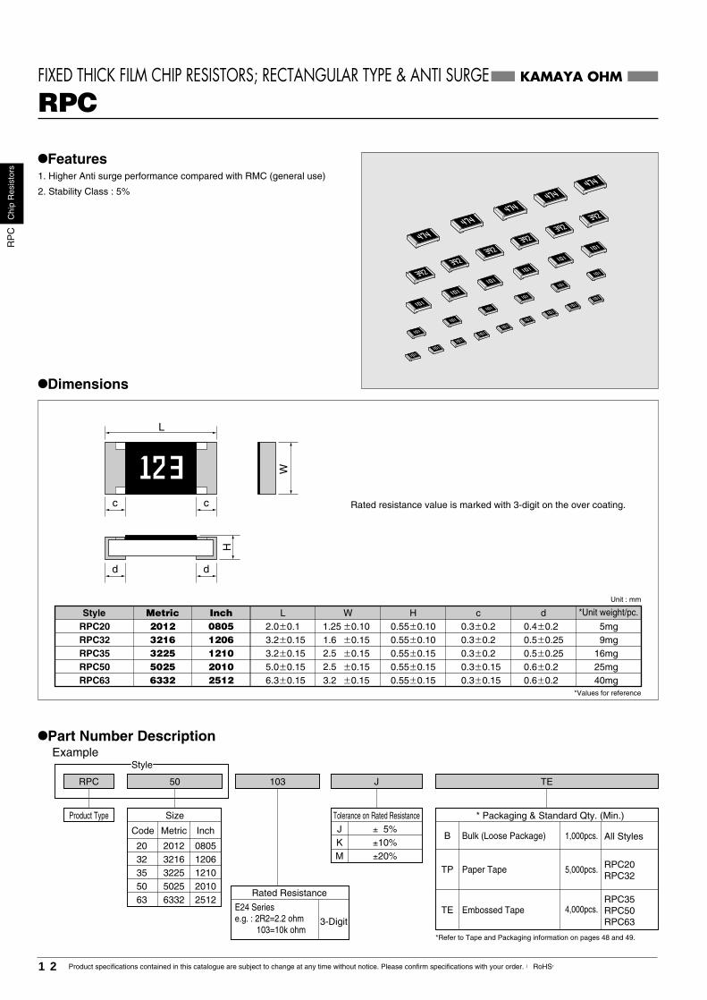
•Features1. Higher Anti surge performance compared with RMC (general use)
2. Stability Class : 5%
•Dimensions
Rated resistance value is marked with 3-digit on the over coating.
Size
Code Metric
20 20123216
50256332
Inch
08051206
20102512
32
5063
Tolerance on Rated ResistanceJ ± 5%K ±10%M ±20%
RPC35RPC50RPC63
RPC20RPC32
Rated Resistance
3-Digit
E24 Seriese.g. : 2R2=2.2 ohm 103=10k ohm
* Packaging & Standard Qty. (Min.)
Bulk (Loose Package)
Paper Tape
Embossed Tape
1,000pcs.
5,000pcs.
4,000pcs.
*Refer to Tape and Packaging information on pages 48 and 49.
•Part Number DescriptionExample
3225 121035
KAMAYA OHM
RPC
�0.15 6.3�0.15 0.55�0.15 0.3�0.15 40mg�0.15 5.0�0.15 0.55�0.15 0.3�0.15 25mg
�0.15 3.2�0.15 0.55�0.10 0.3�0.2 9mg
RPC63
�0.102.0�0.1 0.55�0.10 0.3�0.2 5mg
RPC50
RPC32 3216
50256332
Style WLMetric
1206�0.15 3.2�0.15 0.55�0.15 0.3�0.2 16mgRPC35 3225 1210
20102512
Inch H c dRPC20 2012 0805
FIXED THICK FILM CHIP RESISTORS; RECTANGULAR TYPE & ANTI SURGE
L
c c
W
d d
1.251.6
2.52.5
3.2
0.4�0.20.5�0.250.5�0.250.6�0.20.6�0.2
H
Unit : mm
*Values for reference
*Unit weight/pc.
12 Product specifications contained in this catalogue are subject to change at any time without notice. Please confirm specifications with your order. 【RoHS】
Chi
pR
esis
tors
RP
C

•Ratings
Note1. Rated Voltage = (Rated Dissipation)×(Rated Resistance). (d.c. or a.c. r.m.s. Voltage)Note2. Limiting Element Voltage can only be applied to resistors, when the resistance value is equal to or higher than the critical resistance value.Note3. Critical Resistance Value is the resistance value at which the rated voltage is equal to the limiting element voltage.
* pulse limiting power curve is different from resistance value.* Please contact Kamaya sales department for the details.
Perc
enta
ge o
f the
rate
d di
ssip
atio
n(%
)
Ambient Temperature (°C)
Description Requirements
No breakdown or flashoverR≥1G ohm
∆R≤±(1%+0.05 ohm)No visible damage, legible marking
∆R≤±(5%+0.1 ohm) No visible damage
∆R≤±(5%+0.1 ohm) No visible damage
See Ratings Table
In accordance with Clause 4.17.4.5
∆R≤±(1%+0.05 ohm)
∆R≤±(1%+0.05 ohm) No visible damage
∆R≤±(5%+0.1 ohm) No visible damage, legible marking
∆R≤±(5%+0.1 ohm) No visible damage
No visible damage
∆R≤±(1%+0.05 ohm)
Test Methods
Clause 4.7
Clause 4.13
Clause 4.23
Clause 4.25.1
Clause 4.8
Clause 4.17Clause 4.18
Clause 4.19
Clause 4.24
Clause 4.25.3
Clause 4.32Clause 4.33
500Va.c.,60s
The applied voltage shall be 2.5 times of the rated voltage or twiceof the limiting element voltage, whichever is the less severe, 2s.
Dry/Damp heat(12+12h cycle), first cycle./Cold/Damp heat(12+12h cycle), remaining cycle./ D.C.Load.
Rated voltage, 1.5h"ON", 0.5h"OFF", 70°C, 1,000h
235°C, 2sAfter immersion into the flux, the immersion into soldershall be carried out in Solder bath at 260°C for 5s.
40°C, 95%R.H., 56 days, test a) and b) of Clause 4.24.2.1
155°C, no-load, 1,000h.
5N, 10sRPC20, 32, 35 Amount of bend : 3 mmRPC50, 63 Amount of bend : 1 mm
Bend strength of theface plating
Voltage proof
Overload
Climatic sequence
Endurance at 70°C
Variation of resistancewith temperature
SolderabilityResistance tosoldering heat
Rapid change oftemperature
Damp test, steady state
Endurance at the uppercategory temperatureAdhesion
Pul
se li
miti
ng p
ower
(w
)
Pulse duration (ms)
•Derating CurveThe derated values of dissipation for temperatures in ex-cess of 70°C shall be indicated by the following Curve.
•1Pulse Limiting Power Curve (e.g 100� value for reference)
KAMAYA OHM
RPC32
RPC20
RPC35
RPC50
RPC63
0.125
0.25
0.5
0.75
1.0
100
0�55 15570
FIXED THICK FILM CHIP RESISTORS; RECTANGULAR TYPE & ANTI SURGE RPC
150
200
�200 E24 500 �55��155�0.27�
J(� 5%)
K(�10%)
M(�20%)
22M�
2012(0805)
3216(1206)
3225(1210)
5025(2010)
6332(2512)
StyleRated Dissipation
at 70°CW
Limiting ElementVoltage
V
Temperature Coefficientof Resistance
10-6/°C
Tolerance onRated Resistance
Rated ResistanceRange
Preferred NumberSeries forResistors
IsolationVoltage
V
Category TemperatureRange
°C
Area of recommended operation
Size
(Inch)Metric
+20°C/−55°C/+20°C/+155°C/+20°C
Cycle : −55°C/+155°C 5times
•Climatic Category55/155/56
Lower Category Temperature �55°CUpper Category Temperature �155°CDuration of the Damp heat, Steady-Style Test 56 days 1
10
100
1,000
10,000
1 10 100 1,000
RMC1RMC1RMC1/2RMC1/2RMC1/4RMC1/4RMC1/8RMC1/8RMC1/10RMC1/10
RPC63RPC63RPC50RPC50RPC35RPC35RPC32RPC32RPC20RPC20
RMC1RMC1/2RMC1/4RMC1/8RMC1/10
RPC63RPC50RPC35RPC32RPC20
•Performance Characteristics JIS C 5201-1 : 1998
13Product specifications contained in this catalogue are subject to change at any time without notice. Please confirm specifications with your order. 【RoHS】
Chi
pR
esis
tors
RP
C

471 LFCR 1/4
Product Type
Style
TE
•Features1. FCR is a trimmable device and replaceable with various resistors.
2. Resistance and coating film designed for YAG Laser Trimming.
3. Stability Class : 5%
•Part Number DescriptionExample
Code Rated DissipationRated Dissipation & Size
1/10 0.1W 20123216322550256332
1/8 0.125W1/4 0.25W 1/2 0.5W 1 1.0W
* Packaging & Standard Qty. (Min.)Bulk (Loose Package)B
Paper TapeTP
Embossed Tape
All Styles
FCR1/16FCR1/10FCR1/8
1,000pcs.
5,000pcs.
4,000pcs.FCR1/4FCR1/2FCR1
TE
*Refer to Tape and Packaging information on pages 48 and 49.
Rated Resistance
E24 Seriese.g. : 471=470 ohm
Tolerance on Rated Resistance–
±15%L%0
-30Metric
08051206
0.063W 16081/16 0603
121020102512
Inch
•Dimensions
KAMAYA OHM
FCRTRIMMABLE CHIP RESISTORS; RECTANGULAR TYPE
FCR1 �0.15 6.3�0.15 0.55�0.15 0.6�0.2 0.6�0.2FCR1/2 �0.15 5.0�0.15 0.55�0.15 0.6�0.2 0.6�0.2FCR1/4 �0.15 3.2�0.15 0.55�0.15 0.5�0.25 0.5�0.25FCR1/8 �0.15 3.2�0.15 0.55�0.10 0.5�0.25 0.5�0.25FCR1/10 1.25 �0.102.0�0.1 0.55�0.10 0.4�0.2 0.4�0.22012
3216322550256332
WL
08051206121020102512
H c d
40mg25mg16mg 9mg 5mg
FCR1/16 1.6�0.1 0.45�0.10 0.3�0.1 0.3�0.11608 0603 2mg
W
d d
L
c c
H
1.62.52.53.2
�0.15�0.100.8
Style Metric Inch *Unit weight/pc.Unit : mm
*Values for reference
14 Product specifications contained in this catalogue are subject to change at any time without notice. Please confirm specifications with your order. 【RoHS】
Chi
pR
esis
tors
FC
R

•Ratings
Note1. Rated Voltage = (Rated Dissipation)×(Rated Resistance). (d.c. or a.c. r.m.s. Voltage)Note2. Limiting Element Voltage can only be applied to resistors when the resistance value is equal to or higher than the critical resistance value.Note3. Critical Resistance Value is the resistance value at which the rated voltage is equal to the limiting element voltage.Note4. T.C.R.: ±100×10-6/°C (10 ohm∼1M ohm) is available on your request.Note5. The indicated values of Ratings are in the case without trimming.
Perc
enta
ge o
f the
rate
d di
ssip
atio
n(%
)
Ambient Temperature(°C)
•Performance Characteristics JIS C 5201-1 : 1998
Description Requirements
∆R≤±(1%+0.05 ohm)No visible damage, legible marking
∆R≤±(5%+0.1 ohm) No visible damage
∆R≤±(5%+0.1 ohm) No visible damage
See Ratings Table
In accordance with Clause 4.17.4.5
∆R≤±(1%+0.05 ohm)
∆R≤±(1%+0.05 ohm) No visible damage
∆R≤±(5%+0.1 ohm) No visible damage, legible marking
∆R≤±(5%+0.1 ohm) No visible damage
No visible damage
∆R≤±(1%+0.05 ohm)
Test Methods
Clause 4.7
Clause 4.13
Clause 4.23
Clause 4.25.1
Clause 4.8
Clause 4.17
Clause 4.18
Clause 4.19
Clause 4.24
Clause 4.25.3
Clause 4.32Clause 4.33
The applied voltage shall be 2.5 times of therated voltage or twice of the limiting Element voltage,whichever is of the less severe, 2s.
Dry/Damp heat(12+12h cycle), first cycle/Cold/Damp heat(12+12h cycle), remainingCycle./ D.C.Load.
Rated voltage, 1.5h"ON", 0.5h"OFF", 70°C, 1,000h.
Measuring temperature : +20°C/−55°C/+20°C/+125°C/+20°C
235°C, 2s
After immersion into the flux, the immersioninto solder shall be carried out in Solder bathat 260°C for 5s.
5 cycles between −55°C and +125°C.
40°C, 95%R.H., 56 days, test a) and b) of Clause 4.24.2.1
125°C, no-load, 1,000h.
5N, 10sFCR1/16~1/4 Amount of bend : 3 mmFCR1/2, 1 Amount of bend : 1 mm
Bend strength of theface plating
Voltage proof
Overload
Climatic sequence
Endurance at 70°C
Variation of resistancewith temperature
Solderability
Resistance to solderingheat
Rapid change oftemperature
Damp test, steady state
Endurance at the uppercategory temperatureAdhesion
Note5. The indicated characteristics value is without trimming.
FCR1/16 100Va.c.,60sFCR1/10~1 500Va.c.,60s
No breakdown or flashoverR≥1G ohm
KAMAYA OHM
TRIMMABLE CHIP RESISTORS; RECTANGULAR TYPE FCR
•Derating CurveThe derated values of dissipation for temperatures in excess of70°C shall be indicated by the following Curve.
0.063
FCR1/8 0.125
FCR1/4 0.25
FCR1/2 0.5
FCR1 1.0
FCR1/16
FCR1/10 0.1
�500��200L (�15%)
�(0��30%)�200
�200
E24500
100
�55��125
100
0�55 12570
•Climatic Category55/125/56
Lower Category Temperature �55°CUpper Category Temperature �125°CDuration of the Damp heat, Steady-State Test 56 days
1608(0603)2012
(0805)3216
(1206)3225
(1210)5025
(2010)6332
(2512)
StyleRated Dissipation
at 70°CW
Tolerance onRated Resistance
Preferred NumberSeries for Resistors
IsolationVoltage
V
Category TemperatureRange°C
Combinations of Rated Resistance Range and Temperature Coefficient of Resistance
Temperature Coefficientof Resistance 10-6/°C
Size
(Inch)Metric
Area of recommended operation
1��9.1�10��4.7M�
10��4.7M�
Rated ResistanceRange
200
50
150
Limiting ElementVoltage
V
15Product specifications contained in this catalogue are subject to change at any time without notice. Please confirm specifications with your order. 【RoHS】
Chi
pR
esis
tors
FC
R

RLC 32
Style
K R470 TPF
•Features1. Most suitable for a detection of current in power source circuits,
motor circuits, etc.
2. Raised Rated dissipation compared with RMC (except 2010,2512 size).
3. Stability Class : 5%
•Dimensions
Rated resistance is marked with 4-digit on the over coating. (RLC20~RLC63)RLC10 : only No marking is available.Please contact KAMAYA for marking of RLC16.
•Part Number DescriptionExample
Product Type
Tolerance on Rated ResistanceF �1%G �2%J �5%
e.g.: R050=50m ohm R100=100m ohm 1R00=1 ohm
* Packaging & Standard Qty. (Min.)Bulk (Loose Package)
RLC35RLC50RLC63
B
Paper TapeTPRLC16RLC20RLC32
RLC10
Embossed TapeTE
*Refer to Tape and Packaging information on pages 48 and 49.
All Styles1,000pcs.
5,000pcs.
Paper Tape(2mm pitch)TH 10,000pcs.
4,000pcs.
Rated Resistance
Temperature Coefficient of Resistance
–
K �10010-6/°C0∼�20010-6/°C0∼�25010-6/°C
0∼�30010-6/°C
KAMAYA OHM
RLCFIXED THICK FILM CHIP RESISTORS; RECTANGULAR TYPE & LOW OHM
RLC32 3.1�0.2 �0.1 0.5�0.25 2.0�0.15 �0.1 0.4�0.2
3216
WL
1.25 �0.10�0.15�0.15
08051206
H c
0.4 �0.2
d
�0.2�0.1
�0.1
0.3
�0.05�0.100.25
RLC35 3.1�0.2 0.6 �0.15 0.5�0.25 9mg 5mg
16mg3225 1210 �0.20.31.62.5
�0.15RLC50 5.0�0.2 0.6 �0.15 0.6�0.2 0.6 �0.2 25mg2.5�0.15RLC63 6.3�0.2 0.6 �0.15 0.6�0.2 0.6 �0.2 40mg3.2
0.6RLC20
�0.05RLC10 1.0�0.05 0.2�0.1 1mg
0.6
�0.050.35RLC16 1.6�0.1 0.3�0.1 0.3 �0.1� 0.15
� 0.050.8 2mg�0.100.45
W
d d
L
c c
H
0.5
Unit : mm
*Values for reference
Style Metric Inch *Unit weight/pc.
5025 20106332 2512
2012
1005 04021608 0603
Code Metric InchSize
16 160810 1005
32 3216
50 5025
20 2012
35 3225
63 6332
06030402
1206
2010
0805
1210
2512
16 Product specifications contained in this catalogue are subject to change at any time without notice. Please confirm specifications with your order. 【RoHS】
Chi
pR
esis
tors
RLC

Note1. Rated Current = (Rated Dissipation)/(Rated Resistance)Note2. Rated Voltage = (Rated Dissipation)×(Rated Resistance). (d.c. or a.c. r.m.s. Voltage)
•Rated Resistance
Ambient Temperature (°C)
Perc
enta
ge o
f the
rate
d dis
sipat
ion(%
)
Note3. Other nominal resistances values are also available, please contact KAMAYA for further information.
•Performance Characteristics JIS C 5201-1 : 1998
Description Requirements
∆R≤±1%No visible damage, legible marking
∆R≤±5% No visible damage
∆R≤±5% No visible damage
See Ratings Table
In accordance with Clause 4.17.4.5
∆R≤±1%
∆R≤±1% No visible damage
∆R≤±5% No visible damage, legible marking
∆R≤±5% No visible damageNo visible damage
∆R≤±1%
Test MethodsClause 4.7No breakdown or flashover
R≥1G ohm
Clause 4.13
Clause 4.23
Clause 4.25.1
Clause 4.8
Clause 4.17Clause 4.18
Clause 4.19
Clause 4.24
Clause 4.25.3Clause 4.32
Clause 4.33
RLC10,16 100Va.c.,60sRLC20∼63 500Va.c.,60s
The applied voltage shall be 2.5 times of RatedVoltage, or equivalent current 2s.
Dry/Damp heat(12+12h cycle), first cycle/Cold/Damp heat(12+12h cycle), remainingcycle./ D.C.Load.
Rated current, 1.5h "ON", 0.5h "OFF", 70°C, 1,000h.
Measuring temperature : +20°C/+125°C/+20°C
235°C, 2sAfter immersion into the flux, the immersion into soldershall be carried out in Solder bath at 260°C for 5s.5 cycles between −55°C and +125°C.
40°C, 95%R.H., 56 days, test a) of Clause 4.24.2.1
125°C, no-load, 1,000h.5N, 10sRLC10~35 Amount of bend : 3 mmRLC50, 63 Amount of bend : 1 mmBend strength of the face plating
Voltage proof
Overload
Climatic sequence
Endurance at 70°C
Variation of resistance with temperature
Solderability
Resistance to soldering heat
Rapid change of temperature
Damp test, steady state
Endurance at the upper category temperatureAdhesion
FIXED THICK FILM CHIP RESISTORS; RECTANGULAR TYPE & LOW OHM RLC
•Ratings
KAMAYA OHM
RLC16
RLC10
100m��3.3�
100m��3.3�
0.25
0.125
RLC20
50m��3.3�
0.33
RLC32 0.5
RLC35 0.66
RLC50 0.75
RLC63 1.0
470m��3.3�
200m��430m�
50m��180m� F, G, J
F, G, J
F, G, J
500
100
�55��125
•Derating CurveThe derated values of dissipation for temperatures in excess of 70°C shall be indicated by the following Curve.
100
0�55 12570
0.27 �1.58
0.19 �1.11
0.31 �2.56
0.38 �3.16
0.44 �3.63
0.47 �3.87
0.55 �4.47
�100
0� �200
0� �250
50m�51m�56m�60m�62m�65m�68m�70m�
R050R051R056R060R062R065R068R070
75m� R07580m� R080
•Climatic Category55/125/56
Lower Category Temperature −55°CUpper Category Temperature +125°CDuration of the Damp heat, Steady-State Test 56 days
470m��3.3�
200m��430m�
100m��180m� F, G, J
F, G, J
F, G, J �100
0� �200
0� �250
240m��430m�
100m��220m�0� �300
J
F, J470m��3.3� 0� �200F, G, J
1005(0402)
1608(0603)
2012(0805)3216
(1206)3225
(1210)5025
(2010)6332
(2512)
StyleRated Dissipation
at 70°CW
Rated CurrentRange
A
RatedResistance
Range
Combinations of Rated Resistance Range,Temperature Coefficient of Resistance and Tolerance on Rated Resistance
Rated ResistanceRange
Temperature Coefficientof Resistance 10-6/°C
Tolerance onRated Resistance
IsolationVoltage
V
Category TemperatureRange
°C
Area of recommended operation
Size
(Inch)Metric
Resistance Code82m�90m�91m�100m�110m�120m�130m�150m�
R082R090R091R100R110R120R130R150
160m� R160180m� R180
Resistance Code200m�220m�240m�250m�270m�300m�330m�360m�
R200R220R240R250R270R300R330R360
390m� R390400m� R400
Resistance Code430m�470m�500m�510m�560m�600m�620m�650m�
R430R470R500R510R560R600R620R650
680m� R680700m� R700
Resistance Code750m�800m�820m�900m�910m�1.0�1.1�1.2�
R750R800R820R900R9101R001R101R20
1.3� 1R301.5� 1R50
Resistance Code1.6�1.8�2.0�2.2�2.4�2.7�3.0�3.3�
1R601R802R002R202R402R703R003R30
Resistance Code
0
20
40
60
80
100
120
140
0 25 50 75 100
Rated Power Ratio(%)
RLC63
RLC50
RLC35
RLC32
RLC20RLC16
RLC10
Mesurement Point
•Surface Temperature Rise (Reference)
Sur
face
Tem
p R
ise
(
)℃
*Because values are different, please contact Kamaya salesdepartment for the details about deployment condition and terms of use.
17Product specifications contained in this catalogue are subject to change at any time without notice. Please confirm specifications with your order. 【RoHS】
Chi
pR
esis
tors
RLC
RLS 50
Style
R050 F TE
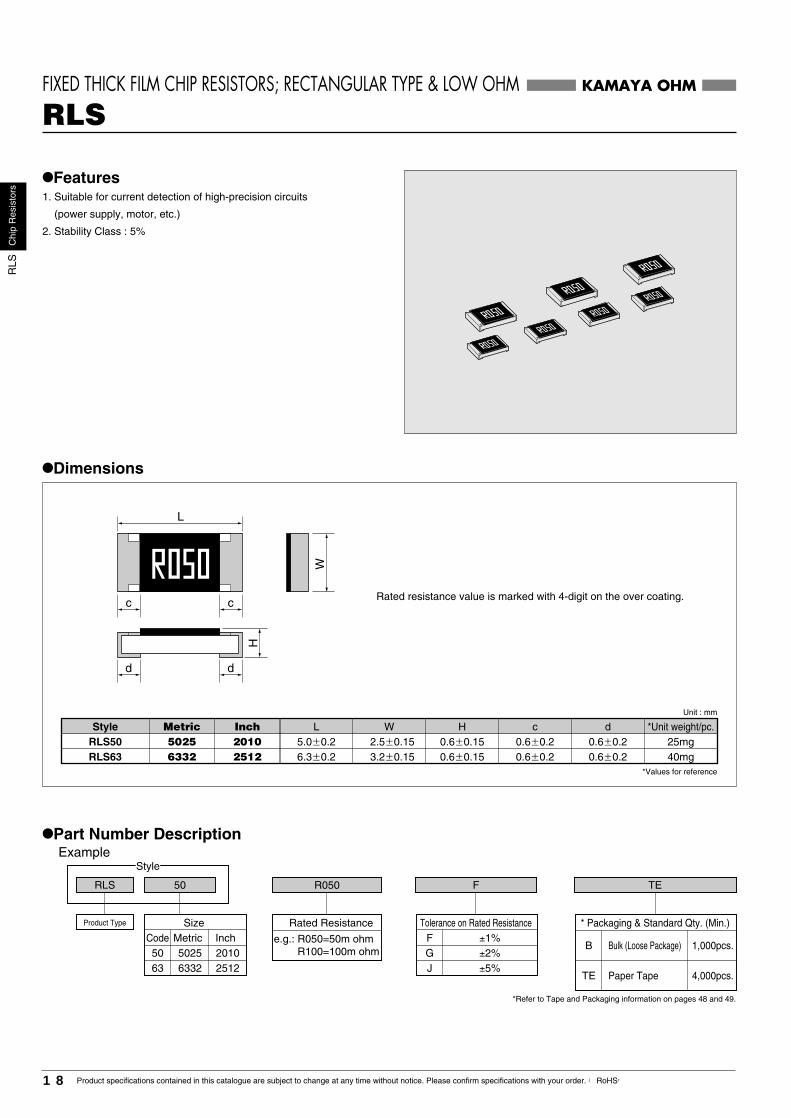
•Features1. Suitable for current detection of high-precision circuits
(power supply, motor, etc.)
2. Stability Class : 5%
•Dimensions
Rated resistance value is marked with 4-digit on the over coating.
•Part Number DescriptionExample
Product Type * Packaging & Standard Qty. (Min.)
Bulk (Loose Package)B
Paper Tape
1,000pcs.
4,000pcs.TE
*Refer to Tape and Packaging information on pages 48 and 49.
Tolerance on Rated Resistance±1%F±2%G±5%J
e.g.: R050=50m ohm R100=100m ohm
Rated ResistanceSizeCode Metric50 502563 6332
Inch20102512
KAMAYA OHM
RLSFIXED THICK FILM CHIP RESISTORS; RECTANGULAR TYPE & LOW OHM
RLS63 3.2�0.156.3�0.2 0.6�0.15 0.6�0.2 0.6�0.2RLS50 2.5�0.155.0�0.2 0.6�0.15 0.6�0.2 0.6�0.25025
6332
WL20102512
H c d
40mg25mg
W
d d
L
c c
H
Unit : mm
*Values for reference
Style Metric Inch *Unit weight/pc.
18 Product specifications contained in this catalogue are subject to change at any time without notice. Please confirm specifications with your order. 【RoHS】
Chi
pR
esis
tors
RLS

FIXED THICK FILM CHIP RESISTORS; RECTANGULAR TYPE & LOW OHM RLS
•Ratings
Note1. Rated Current = (Rated Dissipation)/(Rated Resistance)Note2. Rated Voltage = (Rated Dissipation)×(Rated Resistance). (d.c. or a.c. r.m.s. Voltage)
•Rated Resistance
Note3. Other nominal resistance values are also available, please contact KAMAYA for further information.
•Performance Characteristics JIS C 5201-1 : 1998Description Requirements
No breakdown or flashoverR≥1G ohm
∆R≤±1%No visible damage, legible marking
∆R≤±5% No visible damage
∆R≤±5% No visible damage
See Ratings Table
In accordance with Clause 4.17.4.5
∆R≤±1%
∆R≤±1% No visible damage
∆R≤±5% No visible damage, legible marking
∆R≤±5% No visible damage
No visible damage∆R≤±1%
Test Methods
Clause 4.7
Clause 4.13
Clause 4.23
Clause 4.25.1
Clause 4.8
Clause 4.17Clause 4.18
Clause 4.19
Clause 4.24
Clause 4.25.3
Clause 4.32Clause 4.33
500Va.c.,60s
The rated voltage×2.5 times of Rated Voltage,or equivalent current 2s.
Dry/Damp heat(12+12h cycle), first cycle./Cold/Damp heat(12+12h cycle), remainingcycle./ D.C.Load.
Rated Current, 1.5h "ON", 0.5h "OFF", 70°C, 1,000h.
Measuring temperature : +20°C/+125°C/+20°C
235°C, 2sAfter immersion into the flux, the immersion into soldershall be carried out in Solder bath at 260°C for 5s.
5 cycles between −55°C and +125°C.
40°C, 95%R.H., 56 days, test a) of Clause 4.24.2.1
125°C, no-load, 1,000h.
5N, 10sAmount of bend : 1 mmBend strength of the face plating
Voltage proof
Overload
Climatic sequence
Endurance at 70°C
Variation of resistance with temperature
Solderability
Resistance to soldering heat
Rapid change of temperature
Damp test, steady state
Endurance at the uppercategory temperatureAdhesion
KAMAYA OHM
RLS50 1.93�6.120.75
RLS63 1.0
0�500 �55��125
F(�1%)G(�2%)J(�5%)
•Derating CurveThe derated values of dissipation for temperatures
in excess of 70°C shall be indicated by the following Curve.100
0�55 12570
2.23�7.07
�3500� �2000� �100
20m�
22m�
24m�
25m�
27m�
R020R022R024R025R027
30m� R030
•Climatic Category55/125/56
Lower Category Temperature −55°CUpper Category Temperature +125°CDuration of the Damp heat, Steady-State Test 56 days
5025(2010)
6332(2512)
Resistance Code
Ambient Temperature(°C)
Perc
enta
ge o
f the
rate
d di
ssip
atio
n(%
)
Area of recommended operation
StyleRated Resistance
RangeTemperature Coefficient
of Resistance 10-6/°C
Tolerance onRated Resistance
IsolationVoltage
V
Category TemperatureRange
°C
Combinations of Rated Resistance Range and Temperature Coefficient of ResistanceRated Dissipation
at 70°CW
Rated CurrentRange
A
Size
(Inch)Metric
20m�� 33m�
36m�� 47m�
50m��200m�
33m�
36m�
39m�
40m�
43m�
R033R036R039R040R043
47m� R047
Resistance Code
50m�
51m�
56m�
60m�
62m�
R050R051R056R060R062
65m� R065
Resistance Code
68m�
70m�
75m�
80m�
82m�
R068R070R075R080R082
90m� R090
Resistance Code
91m�
100m�
110m�
120m�
130m�
R091R100R110R120R130
150m� R150
Resistance Code
160m�
180m�
200m�
R160R180R200
Resistance Code
0
20
40
60
80
100
120
140
160
180
0 25 50 75 100
RLS63
RLS50
•Surface Temperature Rise (Reference)
Rated Power Ratio(%)
Mesurement Point
Sur
face
Tem
p R
ise
(
)℃
*Because values are different, please contact Kamaya salesdepartment for the details about deployment condition and terms of use.
19Product specifications contained in this catalogue are subject to change at any time without notice. Please confirm specifications with your order. 【RoHS】
Chi
pR
esis
tors
RLS
RLP
Chi
pR
esis
tors
20 Product specifications contained in this catalogue are subject to change at any time without notice. Please confirm specifications with your order. 【RoHS】
Style
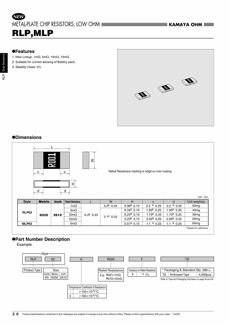
•Features1. New Lineup, 1m�, 5m�, 10m�, 15m�.
2. Suitable for current sensing of Battery pack.
3. Stability Class: 5%
•Dimensions
•Part Number DescriptionExample
Product Type Tolerance on Rated Resistance * Packaging & Standard Qty. (Min.)
*Refer to Tape and Packaging information on page 48 and 49.
Rated Resistance
KAMAYA OHM
RLP,MLPMETAL-PLATE CHIP RESISTORS; LOW OHM
Unit : mm
*Values for reference
Size
RLP63
MLP63
6.3±0.25 0.23±0.153.1±0.25
0.38±0.153.2±0.25
1.75±0.25
2.2 ±0.25
1.75±0.250.23±0.15 0.95±0.25 0.95±0.25
0.51±0.15 1.1 ±0.25 1.1 ±0.25
2.2 ±0.250.34±0.15 1.95±0.25 1.95±0.25
6332 2512
1m�
5m�
10m�
15m�
5m�
50mg 43mg 30mg 26mg 64mg
Rated Resistnace marking is 4digit on over coating.
WLRated Resistace H c dStyle Metric Inch *Unit weight/pc.
Fe.g.: R001=1m�R010=10m�
±1%63 6332 2512
Code Metric Inch
RLP 63 R005 TEF
Embossed TapeTE 4,000pcs.
W
d d
L
c c
H
K
Temperature Coefficient of Resistance–
K
�15010-6/°C�10010-6/°C
NEW

RLP
Chi
pR
esis
tors
21Product specifications contained in this catalogue are subject to change at any time without notice. Please confirm specifications with your order. 【RoHS】
METAL-PLATE CHIP RESISTORS; LOW OHM RLP
KAMAYA OHM
NEW
Note1. Rated Current = (Rated Dissipation)/(Rated Resistance)Note2. Rated Voltage = (Rated Dissipation)×(Rated Resistance). (d.c. or a.c. r.m.s. Voltage)Note3. Please contact Kamaya Sales Dept. for any other resistance values.
Ambient Temperature (°C)
Perc
enta
ge o
f the
rate
d dis
sipat
ion(%
)
•Derating CurveThe derated values of dissipation for temperatures in excess of 70°C shall be indicated by the following Curve.
•Climatic Category55/155/56
Lower Category Temperature −55°CUpper Category Temperature +155°CDuration of the Damp heat, Steady-State Test 56 days
100
0−55 15570
Area of recommended operation
Unit : mm
*Values for reference
AB
YY
X
•Rated Resistance
•Performance Characteristics JIS C 5201-1 : 1998
Description Requirements
∆R≤±1%No visible damage, legible marking
∆R≤±5% No visible damage
∆R≤±5% No visible damage
See Ratings Table
In accordance with Clause 4.17.4.5
∆R≤±1%
∆R≤±1% No visible damage
∆R≤±5% No visible damage, legible marking
∆R≤±5% No visible damageNo visible damage∆R≤±1%
Test Methods
Clause 4.7No breakdown or flashoverR≥1G ohm
Clause 4.13
Clause 4.23
Clause 4.25.1
Clause 4.8
Clause 4.17Clause 4.18
Clause 4.19
Clause 4.24
Clause 4.25.3Clause 4.32Clause 4.33
100Va.c.,60s
The applied voltage shall be 2.5 times of RatedVoltage, or equivalent current 2s.
Dry/Damp heat(12+12h cycle), first cycle/Cold/Damp heat(12+12h cycle), remainingcycle./ D.C.Load.
Rated current, 1.5h "ON", 0.5h "OFF", 70°C, 1,000h.
Measuring temperature : +20°C/+155°C/+20°C
235°C, 2sAfter immersion into the flux, the immersion into soldershall be carried out in Solder bath at 260°C for 5s.5 cycles between −55°C and +155°C.
40°C, 95%R.H., 56 days, test a) of Clause 4.24.2.1
155°C, no-load, 1,000h.5N, 10s Amount of bend : 1 mmBend strength of the face plating
Voltage proof
Overload
Climatic sequence
Endurance at 70°C
Variation of resistance with temperature
Solderability
Resistance to soldering heat
Rapid change of temperature
Damp test, steady state
Endurance at the upper category temperatureAdhesion
Resistance value will be changed by soldering condition.Please design products in consideration of this change of resistance value.
•Recommended land Pattern
•Precautions of use
•Ratings
RLP63
MLP63
2.0
2.0
100
44.7 1mΩ
5mΩ,10mΩ,15mΩ
5mΩ
±150
±100F(±1%)
6332(2512) �55��1551.0 8.16,10,14.1
20
StyleRated Dissipation
at 70°CW
Rated CurrentRange
A
Combination of Rated Resistance Range andTemperature Coefficient of Resistance
Rated ResistanceRange
Temperature Coefficientof Resistance 10-6/°C
Tolerance onRated Resistance
IsolationVoltage
V
Category TemperatureRange
°C
Size
(Inch)Metric
1mΩ
10mΩ15mΩ
R001R0055mΩR010R015
RLP63RLP63・MLP63
RLP63
Resistance CodeStyle
RLP63
MLP63
6332 2512
1mΩ5mΩ10mΩ15mΩ5mΩ
2.02.4
4.0
7.67.6
7.6
3.53.5
3.5
2.82.6
1.8
Style BAMetric Lnch X YRated Resistance
•Surface Temperature Rise (Reference)
0
20
40
60
80
100
120
0 20 40 60 80 100
RLP63 1mΩ SurfaceRLP63 1mΩ Soldering Point
MLP63 5mΩ Surface
RLP63 15mΩ SurfaceMLP63 5mΩ Soldering PointRLP63 10mΩ Surface
RLP63 5mΩ Surface
RLP63 5mΩ Soldering PointRLP63 15mΩ Soldering PointRLP63 10mΩ Soldering Point
Surface
Soldering Point
Mesurement Point
Rated Power Ratio(%)
Sur
face
Tem
p R
ise
(
)℃
*Because values are different, please contact Kamaya salesdepartment for the details about deployment condition and terms of use.
RC
CC
hip
Res
isto
rs
22 Product specifications contained in this catalogue are subject to change at any time without notice. Please confirm specifications with your order. 【RoHS】
Style
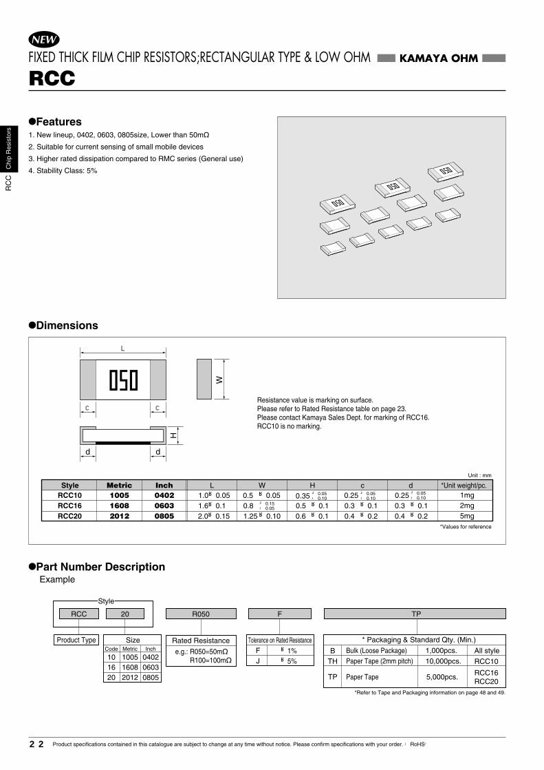
•Features1. New lineup, 0402, 0603, 0805size, Lower than 50m�
2. Suitable for current sensing of small mobile devices
3. Higher rated dissipation compared to RMC series (General use)
4. Stability Class: 5%
•Dimensions
•Part Number DescriptionExample
Product Type Tolerance on Rated Resistance * Packaging & Standard Qty. (Min.)
*Refer to Tape and Packaging information on page 48 and 49.
Rated Resistance
KAMAYA OHM
RCCFIXED THICK FILM CHIP RESISTORS;RECTANGULAR TYPE & LOW OHM
Resistance value is marking on surface.Please refer to Rated Resistance table on page 23. Please contact Kamaya Sales Dept. for marking of RCC16. RCC10 is no marking.
Fe.g.: R050=50m� R100=100m�
±1%J ±5%
RCC 20 R050 TPF
Bulk (Loose Package)BPaper Tape (2mm pitch)TH
Paper Tape TP
2.0±0.15 ±0.1 0.4 ±0.22012 1.25±0.100805 0.4 ±0.2
+ 0.05- 0.100.25
RCC20
±0.05
5mg0.6
RCC10 1.0±0.05 0.251005 0402 1mg 0.35RCC16 1.6±0.1 0.3 ±0.11608 0603 0.3 ±0.1+ 0.15
- 0.05
+ 0.05- 0.10
+ 0.05- 0.10
0.8 2mg±0.10.50.5
WL H c dStyle Metric Inch *Unit weight/pc.
1,000pcs.
10,000pcs.
5,000pcs.
RCC10
All style
RCC16RCC20
*Values for reference
Size
10 1005 040216 1608 060320 2012 0805
Code Metric Inch
W
d d
H
NEW
L
c c
Unit : mm

RC
CC
hip
Res
isto
rs
23Product specifications contained in this catalogue are subject to change at any time without notice. Please confirm specifications with your order. 【RoHS】
Note1. Rated Current = (Rated Dissipation)/(Rated Resistance)Note2. Rated Voltage = (Rated Dissipation)×(Rated Resistance). (d.c. or a.c. r.m.s. Voltage)
•Performance Characteristics JIS C 5201-1 : 1998
Description Requirements
∆R≤±1%No visible damage, legible marking
∆R≤±5% No visible damage
∆R≤±5% No visible damage
See Ratings Table
In accordance with Clause 4.17.4.5
∆R≤±1%
∆R≤±1% No visible damage
∆R≤±5% No visible damage, legible marking
∆R≤±5% No visible damageNo visible damage∆R≤±1%
Test MethodsClause 4.7No breakdown or flashover
R≥1G ohm
Clause 4.13
Clause 4.23
Clause 4.25.1
Clause 4.8
Clause 4.17Clause 4.18
Clause 4.19
Clause 4.24
Clause 4.25.3Clause 4.32Clause 4.33
RCC10,16 100Va.c.,60sRCC20 500Va.c.,60s
The applied voltage shall be 2.5 times of RatedVoltage, or equivalent current 2s.
Dry/Damp heat(12+12h cycle), first cycle/Cold/Damp heat(12+12h cycle), remainingcycle./ D.C.Load.
Rated current, 1.5h "ON", 0.5h "OFF", 70°C, 1,000h.
Measuring temperature : +20°C/+125°C/+20°C
235°C, 2sAfter immersion into the flux, the immersion into soldershall be carried out in Solder bath at 260°C for 5s.5 cycles between −55°C and +125°C.
40°C, 95%R.H., 56 days, test a) of Clause 4.24.2.1
125°C, no-load, 1,000h.5N, 10s Amount of bend : 3 mmBend strength of the face plating
Voltage proof
Overload
Climatic sequence
Endurance at 70°C
Variation of resistance with temperature
Solderability
Resistance to soldering heat
Rapid change of temperature
Damp test, steady state
Endurance at the upper category temperatureAdhesion
FIXED THICK FILM CHIP RESISTORS;RECTANGULAR TYPE & LOW OHM RCC
•Ratings
KAMAYA OHM
•Derating CurveThe derated values of dissipation for temperatures in excess of70°C shall be indicated by the following Curve.
RCC10 1.110.125100
500
�55��125
~1.9433m� ~ 50m� 0~+35051m� ~100m� ±15033m� ~ 50m� 0~+25051m� ~100m� ±15020m� ~ 27m� 0~+25030m� ~ 50m� ±150
F (±1%)
J (±5%)
1005(0402)
RCC16 1.580.25 ~2.751608(0603)
RCC20 2.560.33 ~4.062012(0805)
StyleRated Dissipation
at 70°CW
Rated CurrentRange
A
IsolationVoltage
V
Category TemperatureRange
°C
Size
(Inch)Metric
100
0-55 12570Ambient Temperature (°C)
Perc
enta
ge o
f the
rate
d dis
sipat
ion(%
)
Area of recommended operation
20m�22m�24m�25m�27m�30m�33m�36m�39m�
R020R022R024R025R027R030R033R036R039
40m�43m�47m�50m�51m�56m�60m�62m�65m�
R040R043R047R050R051R056R060R062R065
68m�70m�75m�80m�82m�90m�91m�
100m�
R068R070R075R080R082R090R091R100
•Rated ResistanceResistance Code Resistance CodeResistance Code
020022024025027030033036039
040043047050051056060062065
068070075080082 90091R10
Mark MarkMark
•Precautions of useResistive element is on bottom surface.Please note for inspection of parts existence & nonexistence, inversion mounting by Inspection machine.Resistance value will be changed by soldering condition.Please design products in consideration of this change of resistance value.
1.
2.
Combination of Rated Resistance Range andTemperature Coefficient of Resistance
Rated ResistanceRange
Temperature Coefficientof Resistance 10-6/°C
Tolerance onRated Resistance
NEW
Please contact Kamaya Sales Dept. for any other resistance values.
0
5
10
15
20
25
30
35
40
45
50
0 25 50 75 100
RCC20 Surface
RCC16 Surface
RCC20 Soldering Point
RCC16 Soldering Point
RCC10 Surface
RCC10 Soldering Point
Soldering Point
•Surface Temperature Rise (Reference)
Rated Power Ratio(%)
Sur
face
Tem
p R
ise
(
)℃
Surface
Mesurement Point
•Climatic Category55/125/56
Lower Category Temperature −55°CUpper Category Temperature +125°CDuration of the Damp heat, Steady-State Test 56 days
*Because values are different, please contact Kamaya salesdepartment for the details about deployment condition and terms of use.

RH
CC
hip
Res
isto
rs
24 Product specifications contained in this catalogue are subject to change at any time without notice. Please confirm specifications with your order. 【RoHS】
RHC 20
Style
75G0 M TP
•Features 1. Max. resistance value : 150G ohm.
2. Suitable for compact instrumentation, infrared rays, sensors, etc.
•Dimensions
•Part Number DescriptionExample
Product Type Size
20 201216 1608
Tolerance on Rated Resistance
M ±20%K ±10%J ± 5%
NH
±30%±50%
08050603InchCode Metric
Rated Resistance * Packaging & Standard Qty. (Min.)Bulk (Loose Package)BPaper Tape
1,000pcs.5,000pcs.TP
*Refer to Tape and Packaging information on pages 48 and 49.
e.g.: 100M=100M ohm 1G00=1G ohm 10G0=10G ohm 100G=100G ohm
RHC20 1.25�0.10 0.4�0.2 0.4�0.2RHC16 0.3�0.1 0.3�0.11608
2012
WL0.45�0.100.55�0.10
1.6�0.12.0�0.1
06030805
H c d�0.15�0.050.8
5mg2mg
KAMAYA OHM
RHCFIXED THICK FILM CHIP RESISTORS; RECTANGULAR TYPE & HIGH OHM
W
d d
H
L
c c
*Unit weight/pc.Style Metric InchUnit : mm
*Values for reference

RH
CC
hip
Res
isto
rs
25Product specifications contained in this catalogue are subject to change at any time without notice. Please confirm specifications with your order. 【RoHS】
FIXED THICK FILM CHIP RESISTORS; RECTANGULAR TYPE & HIGH OHM RHC
•Ratings
Ambient Temperature(°C)
Perc
enta
ge o
f loa
d (%
)
Within specified tolerance
Solderability
Rapid change oftemperature
Moisture resistance property (steady state)
Temperature characteristicof resistance
Resistance
Endurance at 70°C(rated load)
Resistance to solderingheat
Voltage coefficient
Capacity
5.2 clause Measuring temperature: 5°C/35°C
5.3 clause Measuring voltage: 5V/15V
See Rating Table
•Performance Characteristics
5.1 clause Measuring voltage: 15V
6.11 clause Dip into 235°C solder bath for 2s.
6.10 clause Dip into 260°C solder bath for 10s.
7.4 clause Cycle between −55°C and +125°C for 5 cycles.
7.5 clause 40°C, 90∼95%R.H., 1,000h.
Measuring voltage: 1V, Measuring frequency: 10k, 100k, 1MHz.
7.10 clause Rated voltage, 1.5 h "ON", 0.5h "OFF", 70°C, 1,000h.
RHC16 RHC20
At least 10T ohmInsulation resistance 5.6 clause 100Vd.c., 60s
At least 95% of the terminal surface must be covered by new solder
100M ohm≤R<100G ohm : within ±1%/V100G ohm≤R≤150G ohm : within ±2%/V
100M ohm≤R≤10G ohm : within 0∼−2%/V100G ohm≤R≤150G ohm : within ±10%/V
100M ohm≤R≤10G ohm : within ±1%10G ohm<R≤150G ohm : within ±2%
100M ohm≤R≤10G ohm : within ±1%100G ohm≤R≤150G ohm : within ±5%
100M ohm≤R≤10G ohm : within ±1%10G ohm<R≤150G ohm : within ±2%
100M ohm≤R≤10G ohm : within ±1%100G ohm≤R≤150G ohm : within ±5%
100M ohm≤R≤10G ohm : within ±2%10G ohm<R≤150G ohm : within ±5%
100M ohm≤R≤10G ohm : within ±2%100G ohm≤R≤150G ohm : within ±5%
100M ohm≤R≤10G ohm : within ±3%10G ohm<R≤150G ohm : within ±5%
100M ohm≤R≤10G ohm : within ±3%100G ohm≤R≤150G ohm : within ±20%
1.0pF or less
No major visible damage
No major visible damage
No major visible damage
No major visible damage
Test Method JIS C5202-1990Description Requirements
KAMAYA OHM
RHC20
RHC16
15 100 �55��125
0��2,000
�2,000
�4,000
•Derating CurveThe derated values of load for temperatures in excess of70°C shall be indicated by the following Curve.
100
0�55 12570
100M�100M�
100G�
100M�
100M�
100M�
�
�
�
�
�
�
270M�1G�
150G�
150G�
1G�
10G�
(� 5%)
(�10%)
(�20%)(�30%)(�50%)(� 5%)(�10%)
(�20%)(�30%)(�50%)
J
K
MNHJK
MNH
1608(0603)
2012(0805)
Area of recommended operation
StyleRated
VoltageV
Temperature Coefficientof Resistance
10-6/°C
Tolerance onRated Resistance
Preferred Numberseries for resistors
E12
IsolationVoltage
V
Rated ResistanceRange
Category TemperatureRange
°C
Size
(Inch)Metric
RA
CC
hip
Res
isto
rN
etw
orks
26 Product specifications contained in this catalogue are subject to change at any time without notice. Please confirm specifications with your order. 【RoHS】
0.8
0.65
0.8 0.3 �0.2 0.25�0.100.15�0.100.15�0.10
0.25�0.15
0.33
0.6 0.5 �0.1 0.35�0.1
−
0.45 0.25�0.10 0.5 3.5mg
1.1mg
7mg
2.1mg−
0.4 �0.15
0.35�0.05
0.45�0.1
0.5 �0.1 0.35�0.05
0.5 �0.1
1.0�0.05
1.6�0.11.0�0.1
1.6�0.1
1.0�0.05
1.6�0.1 2.0�0.1
3.2�0.1
CCAC
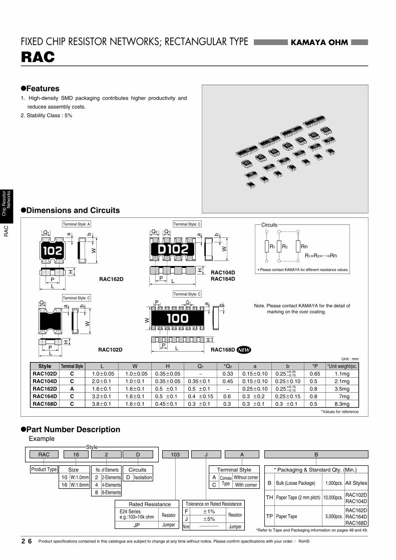
RAC102DRAC104DRAC162DRAC164D
�0.05�0.100.25
�0.15�0.100.25
RAC 16Style
2 103 A BJD
KAMAYA OHM
•Features1. High-density SMD packaging contributes higher productivity and
reduces assembly costs.
2. Stability Class : 5%
RACFIXED CHIP RESISTOR NETWORKS; RECTANGULAR TYPE
•Dimensions and Circuits
R1=R2=...=Rn
Rn
CircuitsTerminal Style: A
RAC104DRAC164D
Terminal Style: C
Terminal Style: C
• Please contact KAMAYA for different resistance values.
Note. Please contact KAMAYA for the detail of marking on the over coating.
H
LP
Q1Q2 a
R1 R2
*Unit weight/pc.Unit : mm
*Values for reference
*Pba*Q2Q1HWLStyle Terminal Style
•Part Number DescriptionExample
Product Type
10 W:1.0mm16 W:1.6mm
No. of Elements2 2-Elements4 4-Elements
CircuitsD Isolation
Terminal StyleWithout cornerWith corner
A ConvexTypeC
* Packaging & Standard Qty. (Min.)
Bulk (Loose Package)B
Paper TapeTPRAC162DRAC164DRAC168D
RAC102DRAC104D
Paper Tape (2 mm pitch)TH
*Refer to Tape and Packaging information on pages 48 and 49.
All Styles1,000pcs.
5,000pcs.
10,000pcs.8 8-Elements
Rated Resistance
Size
E24 Seriese.g.:103=10k ohm
JP
Resistor
Jumper
Tolerance on Rated Resistance
�5%JNone
Resistor�1%F
Jumper
W
bQ1
H
W
LP
ba
RAC162D
0.5 0.3 �0.1 0.3 �0.10.3 8.3mg 0.3 �0.1 1.6�0.1 3.8�0.1 CRAC168D
RAC102D RAC168DP
H
WbQ2
L
a a bP
W
Q1
Terminal Style: C
LPNEW
H

RA
CC
hip
Res
isto
rN
etw
orks
27Product specifications contained in this catalogue are subject to change at any time without notice. Please confirm specifications with your order. 【RoHS】
FIXED CHIP RESISTOR NETWORKS; RECTANGULAR TYPE RAC
Note1. Rated Voltage = (Rated Dissipation)×(Rated Resistance). (d.c. or a.c. r.m.s. Voltage)Note2. Limiting Element Voltage can only be applied to resistors when the resistance value is equal to or higher than the critical resistance value.Note3. Critical Resistance Value is the resistance value at which the rated voltage is equal to the limiting element voltage.
•Performance Characteristics JIS C 5201-1 : 1998
Description Requirements Test Methods
Clause 4.7
Clause 4.13
Clause 4.23
Clause 4.25.1
Clause 4.8
Clause 4.17
Clause 4.18
Clause 4.19
Clause 4.25.3
Clause 4.32
Clause 4.33
RAC102D, 104D 50Va.c.,60sRAC162D, 104D, 168D 100Va.c.,60s
The applied voltage shall be 2.5 times of therated voltage or twice of the limitingelement voltage, whichever is the less severe, 2s.
Rated voltage, 1.5h "ON", 0.5h "OFF",70°C, 1,000h.
Measuring temperature : +20°C/−55°C/+20°C/+125°C/+20°C
235°C, 2s
After immersion into the flux, theImmersion into solder shall be carried outin Solder bath at 260°C for 5s.
5 cycles between −55°C and +125°C.
125°C, no-load, 1,000h.
5N, 10s
Bend strength of theface plating
Voltage proof
Overload
Climatic sequence
Endurance at 70°C
Variation of resistancewith temperature
Solderability
Resistance to solderingheat
Rapid change oftemperature
Damp test, steady state
Endurance at the uppercategory temperature
Adhesion
No breakdown or flashoverR≥1G ohm
∆R≤±(1%+0.05 ohm)No visible damage, legible marking
∆R≤±(5%+0.1 ohm) No visible damage
∆R≤±(5%+0.1 ohm) No visible damage
See Ratings Table
In accordance with Clause 4.17.4.5
∆R≤±(1%+0.05 ohm)
∆R≤±(1%+0.05 ohm) No visible damage
∆R≤±(5%+0.1 ohm) No visible damage, legible marking
∆R≤±(5%+0.1 ohm) No visible damage
No visible damage
∆R≤±(1%+0.05 ohm)
Dry/Damp heat(12+12h cycle), first cycle./Cold/Damp heat(12+12h cycle), remainingcycle./ D.C.Load.
Amount of bend : 3 mm
Clause 4.24 40°C, 95%R.H., 56 days, test a) and b) of Clause 4.24.2.1
KAMAYA OHM
•Derating CurveThe derated values of dissipation for temperatures in excess of70°C shall be indicated by the following Curve.(For Jumpers the load current shall be derated according to the Derating Curve)
100
0�55 12570
•Climatic Category55/125/56
Lower Category Temperature −55°CUpper Category Temperature +125°CDuration of the Damp heat, Steady-State Test 56 days
Ambient Temperature(°C)
Perc
enta
ge o
f the
rate
d di
ssip
atio
n(cu
rrent
)(%)
Area of recommended operation
•Ratings
RAC102D
RAC104D
RAC162D
RAC164D
RAC168D
0.125
0.063
0.25
0.125
0.25
0.25
1.0
25
25
�20050
J(�5%)
F(�1%)J(�5%)
J(�5%)
50
�55��125E2410��1M�
100
W/Element W/pc.
Rated Dissipationat 70°CStyle
Rated Currentof Jumper
A
Limiting ElementVoltage
V
Temperature Coefficientof Resistance
10-6/°C
Rated ResistanceRange
Tolerance on Rated Resistance
Preferred NumberSeries forResistors
IsolationVoltage
V
Category TemperatureRange°C
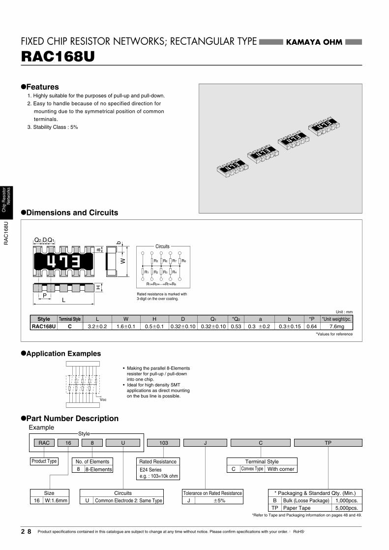
RA
C16
8UC
hip
Res
isto
rN
etw
orks
28 Product specifications contained in this catalogue are subject to change at any time without notice. Please confirm specifications with your order. 【RoHS】
RAC 16
Style
8 C TP103 JU
KAMAYA OHM
•Features 1. Highly suitable for the purposes of pull-up and pull-down.
2. Easy to handle because of no specified direction for
mounting due to the symmetrical position of common
terminals.
3. Stability Class : 5%
RAC168UFIXED CHIP RESISTOR NETWORKS; RECTANGULAR TYPE
R1
R1=R2=...=R7=R8
R2 R3 R4
R5 R6 R7 R8
•Dimensions and Circuits
Rated resistance is marked with3-digit on the over coating.
CircuitsQ1Q2 D
a
L
Wb
H
P
Unit : mm
*Values for reference
0.640.3 �0.2 0.3�0.15*Q2
0.530.32�0.100.5�0.1 0.32�0.101.6�0.13.2�0.2RAC168U*Unit weight/pc.*PbaQ1
7.6mgH DWLStyle Terminal Style
C
•Application Examples
• Making the parallel 8-Elements resister for pull-up / pull-down into one chip.
• Ideal for high density SMT applications as direct mounting on the bus line is possible.
Vcc
•Part Number DescriptionExample
Product Type
* Packaging & Standard Qty. (Min.)Bulk (Loose Package)BPaper Tape
1,000pcs.5,000pcs.TP
Tolerance on Rated ResistanceJ �5%
Rated Resistance
E24 Seriese.g. : 103=10k ohm
CircuitsU
No. of Elements8 8-Elements
*Refer to Tape and Packaging information on pages 48 and 49.
Terminal StyleWith cornerC
Size16 W:1.6mm
Convex Type
Common Electrode 2: Same Type
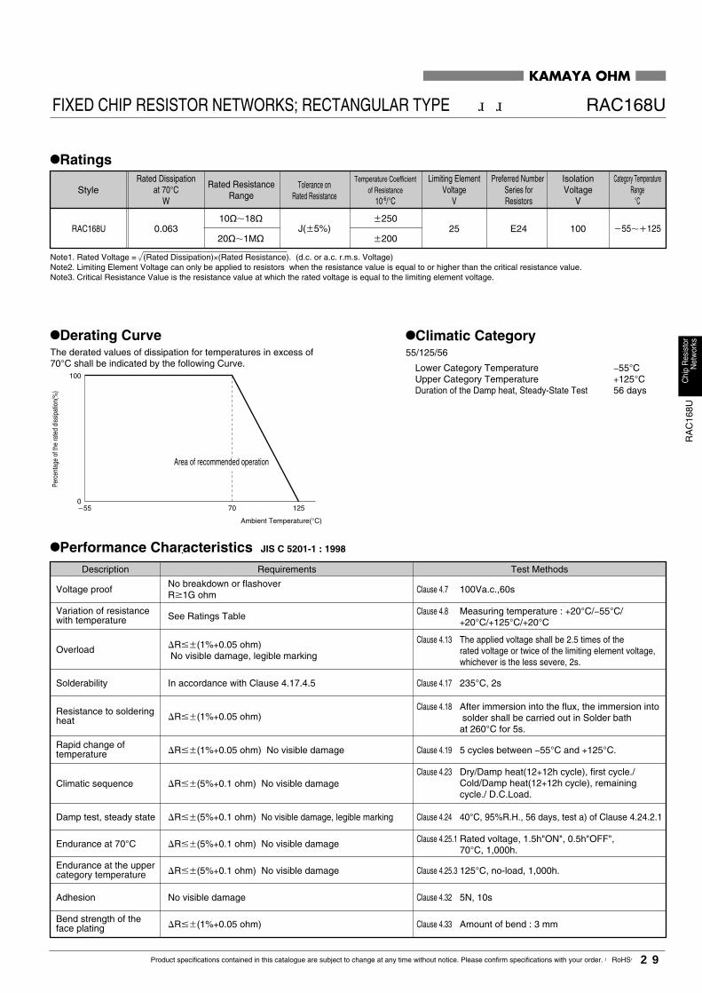
RA
C16
8UC
hip
Res
isto
rN
etw
orks
29Product specifications contained in this catalogue are subject to change at any time without notice. Please confirm specifications with your order. 【RoHS】
FIXED CHIP RESISTOR NETWORKS; RECTANGULAR TYPE RAC168U
Ambient Temperature(°C)
Perc
enta
ge o
f the
rate
d di
ssip
atio
n(%
)
•Derating CurveThe derated values of dissipation for temperatures in excess of70°C shall be indicated by the following Curve.
KAMAYA OHM
RAC168U 0.063 25�250
�200
10��18�
20��1M�J(�5%) E24 100 �55��125
100
0�55 12570
•Climatic Category55/125/56
Lower Category Temperature −55°CUpper Category Temperature +125°CDuration of the Damp heat, Steady-State Test 56 days
StyleRated Dissipation
at 70°CW
Limiting ElementVoltage
V
Temperature Coefficientof Resistance
10-6/°C
Tolerance onRated Resistance
Rated ResistanceRange
Preferred Number Series forResistors
IsolationVoltage
V
Category TemperatureRange
°C
Note1. Rated Voltage = (Rated Dissipation)×(Rated Resistance). (d.c. or a.c. r.m.s. Voltage)Note2. Limiting Element Voltage can only be applied to resistors when the resistance value is equal to or higher than the critical resistance value.Note3. Critical Resistance Value is the resistance value at which the rated voltage is equal to the limiting element voltage.
Description Requirements Test Methods
Clause 4.7
Clause 4.13
Clause 4.23
Clause 4.25.1
Clause 4.8
Clause 4.17
Clause 4.18
Clause 4.19
Clause 4.25.3
Clause 4.32
Clause 4.33
100Va.c.,60s
The applied voltage shall be 2.5 times of therated voltage or twice of the limiting element voltage,whichever is the less severe, 2s.
Rated voltage, 1.5h"ON", 0.5h"OFF",70°C, 1,000h.
Measuring temperature : +20°C/−55°C/+20°C/+125°C/+20°C
235°C, 2s
After immersion into the flux, the immersion into solder shall be carried out in Solder bathat 260°C for 5s.
5 cycles between −55°C and +125°C.
125°C, no-load, 1,000h.
5N, 10s
Bend strength of theface plating
Voltage proof
Overload
Climatic sequence
Endurance at 70°C
Variation of resistancewith temperature
Solderability
Resistance to solderingheat
Rapid change oftemperature
Damp test, steady state
Endurance at the uppercategory temperature
Adhesion
No breakdown or flashoverR1G ohm
�R��(1%+0.05 ohm)No visible damage, legible marking
�R��(5%+0.1 ohm) No visible damage
�R��(5%+0.1 ohm) No visible damage
See Ratings Table
In accordance with Clause 4.17.4.5
�R��(1%+0.05 ohm)
�R��(1%+0.05 ohm) No visible damage
�R��(5%+0.1 ohm) No visible damage, legible marking
�R��(5%+0.1 ohm) No visible damage
No visible damage
�R��(1%+0.05 ohm)
Dry/Damp heat(12+12h cycle), first cycle./Cold/Damp heat(12+12h cycle), remainingcycle./ D.C.Load.
Amount of bend : 3 mm
Clause 4.24 40°C, 95%R.H., 56 days, test a) of Clause 4.24.2.1
Area of recommended operation
•Ratings
•Performance Characteristics JIS C 5201-1 : 1998

KAMAYA OHM
FCC,FHCCHIP FUSES; RECTANGULAR TYPE
•Part Number DescriptionExample
•Dimensions
L
c c
W
d d
Unit : mm
*Values for reference
FCC32FHC32
1.6 �0.15 0.5�0.25
FCC16FHC16
0.3�0.15
0.5 �0.25
0.3 �0.1 1608
3216
Style WL
0.45�0.10
0.65�0.100.6 �0.1
1.6�0.1
3.2�0.2
Metric
0603
1005 0402
1206
Inch H c d *Unit weight/pc.
2mg
0.2�0.10 0.25�0.10 0.4 �0.1 1.0�0.05 0.8mg
1.25�0.10
0.5 �0.05
FCC20FHC20
0.4�0.2 0.4 �0.2 2012 0.6 �0.12.0�0.10805 6mg
10mg11mg
USC
H
�0.15�0.050.8
FCC10FHC10
FCC 20
Product Type
Style
202 AD TP
•Features1. Fast-Acting Type
2. Suitable for over-current protection of the circuit of miniture portable
equipment.
3. 4 sizes available : from 0402 to 1206.
4. No smoke, no flame, at the fusing conditions.
5. Certified UL and c-UL.
•File No.: E176847
6. Major applications
•PC related equipment and peripherals (PC, Hard Drive, Printer etc.). •Small portable devices (Mobile phone, PDA Battery Charger etc.).•Digital Camera (Digital still camera).•Game equipment.
Current value is marked on the over coating.Please refer to Ratings Table on next page.
Size
10 1005Code Metric
20060316 16080402 3-DigitInch
08052012120632 3216
Rated Current
e.g. : 501=0.5A 132=1.25A 202=2.0A
Option CodeCode Clearing Time
ABWithin 5s under 200%
of Rated Current
AAWithin 120s under
200% of Rated Current
ADWithin 5s under 250%
of Rated Current
FCCFHC
B
Paper Tape
1,000pcs.
5,000pcs.
All Styles
FCC16FHC16FCC20FHC20FCC32FHC32
TP
10,000pcs. FCC10FHC10
PA
* Packaging & Standard Qty. (Min.)
*Refer to Tape and Packaging information on pages 48 and 49.
Bulk (Loose Package)
Press-PocketPaper Tape (2mm pitch)
30 Product specifications contained in this catalogue are subject to change at any time without notice. Please confirm specifications with your order. 【RoHS】
Chi
pF
uses
FC
CF
HC
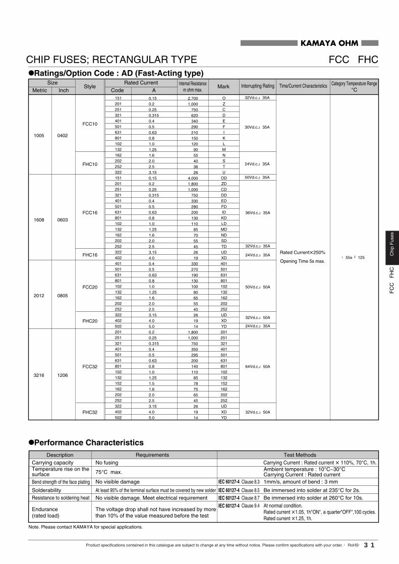
KAMAYA OHM
CHIP FUSES; RECTANGULAR TYPE FCC FHC
•Ratings/Option Code : AD (Fast-Acting type)
•Performance Characteristics
The voltage drop shall not have increased by morethan 10% of the value measured before the test
75°C max.
Description RequirementsCarrying capacity
No visible damage
SolderabilityNo visible damage. Meet electrical requirement
Endurance(rated load)
At least 95% of the terminal surface must be covered by new solder
Bend strength of the face plating
Temperature rise on thesurface
Resistance to soldering heat
Clause 8.3
No fusing
1mm/s, amount of bend : 3 mm
Carrying Current : Rated current � 110%, 70°C, 1h.
Clause 8.5 Be immersed into solder at 235°C for 2s.Clause 8.7 Be immersed into solder at 260°C for 10s.Clause 9.4 At normal condition.
Rated current �1.05, 1h"ON", a quarter"OFF",100 cycles.Rated current �1.25, 1h.
Ambient temperature : 10°C~30°CCarrying Current : Rated current
Test Methods
Note. Please contact KAMAYA for special applications.
IEC 60127-4
IEC 60127-4IEC 60127-4IEC 60127-4
StyleSize
InchMetricMarkInternal Resistance
m ohm max.Interrupting Rating Time/Current Characteristics Category Temperature Range
°CCode ARated Current
151201251321401501631801102132162202252322151201251321401501631801102132162202252322402401501631801102132162202252322402502201251321401501631801102132152162202252322402502
OZCDEFIKLMNSTU
ODZDCDDDEDFDIDKDLDMDNDSDTDUDXD401501631801102132162202252UDXDYD201251321401501631801102132152162202252UDXDYD
0.150.20.250.3150.40.50.630.81.01.251.62.02.53.150.150.20.250.3150.40.50.630.81.01.251.62.02.53.154.00.40.50.630.81.01.251.62.02.53.154.05.00.20.250.3150.40.50.630.81.01.251.51.62.02.53.154.05.0
2,7001,000
7506203402902101501209055403626
4,0001,8001,000
750330280200130110857055452619
33027019013010080655540261914
1,8001,000
7503502952001401108578756545261914
FCC10
1005 0402
1608 0603
2012 0805
3216 1206
FHC10
FCC16
FHC16
FCC20
FCC32
FHC20
FHC32
24Vd.c. 35A
36Vd.c. 35A
32Vd.c. 35A
50Vd.c. 50A
64Vd.c. 50A
32Vd.c. 50A
30Vd.c. 35A
24Vd.c. 35A
50Vd.c. 35A
32Vd.c. 35A
32Vd.c. 50A
24Vd.c. 35A
-55~+125Rated Current�250%
Opening Time 5s max.
31Product specifications contained in this catalogue are subject to change at any time without notice. Please confirm specifications with your order. 【RoHS】
Chi
pF
uses
FC
CF
HC

FC
CF
HC
Chi
pF
uses
32 Product specifications contained in this catalogue are subject to change at any time without notice. Please confirm specifications with your order. 【RoHS】
KAMAYA OHM
CHIP FUSES; RECTANGULAR TYPE FCC FHC
�55��125
501631801102132162202252
501631801102132162202252
0.50.630.81.01.251.62.02.5
27019013010080655540
2012 0805 FCC20 50Vd.c. 50ARated Current 200%
Opening Time 120s max.
•Ratings/Option Code : AB (Fast-Acting type)
StyleSize
CodeInchMetric ARated Current
MarkInternal Resistancem ohm max.
Interrupting Rating Time/Current Characteristics Category Temperature Range°C
Please contact Kamaya Sale Dept, if you need to confirm Inrush current endurance, Anti-pulse performance etc.We can provide Application Guide for FCC, FHC selection.
NOTE
•Recommended Derating for Rated Current
� Nominal Derating
Option Code AD:Nominal Derating � 80% of Rated Current
Option Code AB:Nominal Derating � 70% of Rated Current
� Temperature Derating
Please refer to the following graph regarding the current derating value for ambient temperature.
Ex.) If FCC16 102AB (Rated Current:1.0A) is used under ambient temperature 70°C,Kamaya recommends, less than the current value derated as below,
Rated Current:1.0A (Nominal Derating : 70%Temperature Derating : 100%) =0.7A
100
0-55 12570
Ambient Temperature(°C)
Temperature Derating
Perc
enta
ge o
f the
rate
d cu
rrent
(%)
StyleSize
CodeInchMetric ARated Current
MarkInternal Resistancem ohm max.
Interrupting Rating Time/Current Characteristics Category Temperature Range°C
201
251
321
401
501
631
751
801
102
132
152
162
202
252
201
251
321
401
501
631
751
801
102
132
152
162
202
252
501
631
801
102
132
162
202
252
Z
C
D
E
F
I
A
K
L
M
H
N
S
T
ZB
CB
DB
EB
FB
IB
AB
KB
LB
MB
HB
NB
SB
TB
FB
IB
KB
LB
MB
NB
SB
TB
0.2
0.25
0.315
0.4
0.5
0.63
0.75
0.8
1.0
1.25
1.5
1.6
2.0
2.5
0.2
0.25
0.315
0.4
0.5
0.63
0.75
0.8
1.0
1.25
1.5
1.6
2.0
2.5
0.5
0.63
0.8
1.0
1.25
1.6
2.0
2.5
2,400
1 ,000
750
620
340
290
220
210
150
120
100
90
55
40
3,200
1,800
1,000
750
330
280
210
200
130
110
95
85
70
40
330
270
190
130
100
80
65
40
1005 0402
1608 0603
2012 0805
FCC10
FHC10
FCC16
FHC16
FCC20
FHC20
36Vd.c. 35A
32Vd.c. 35A
50Vd.c. 50A
32Vd.c. 50A
30Vd.c. 35A
24Vd.c. 35A
-55~+125Rated Current 200%
Opening Time 5s max.
•Option Code : AA (Fast-Acting type)

FC
CF
HC
Chi
pF
uses
33Product specifications contained in this catalogue are subject to change at any time without notice. Please confirm specifications with your order. 【RoHS】
KAMAYA OHM
CHIP FUSES; RECTANGULAR TYPE FCC FHC
Fusing Current(A)
Fus
ing
Tim
e(s)
Fusing Current(A)
Fus
ing
Tim
e(s)
Fusing Current(A)
Fus
ing
Tim
e(s)
Fusing Current(A)
Fus
ing
Tim
e(s)
Fusing Current(A)
Fus
ing
Tim
e(s)
•Time / Current Characteristics
FCC20 AB : 0.5A~2.0A FHC20 AB : 2.5A
FCC20 AD : 0.4A~2.5A FHC20 AD : 3.15A~5.0A
0.1 1 10 100
100
10
0.01
0.001
1
0.1
0.1 1 10 100
100
10
0.01
0.001
1
0.1
0.1 1 10 100
100
10
0.01
0.001
1
0.1
FCC16 AD : 0.15A~2.5A FHC16 AD : 3.15A~4.0A
0.15A
0.2A0.25A
0.315A
0.4A0.5A0.63A
0.8A1.0A1.25A
1.6A2.0A2.5A3.15AFCC10 AD : 0.15A~1.25A
FHC10 AD : 1.6A~3.15A
0.15A
0.2A0.25A
0.315A
0.4A0.5A0.63A
0.8A1.0A1.25A
1.6A2.0A2.5A3.15A
4.0A
FCC10 AB : 0.2A~1.6A FHC10 AB : 2.0A~2.5A
FCC16 AB : 0.2A~2.0A FHC16 AB : 2.5A
0.2A0.25A
0.315A
0.4A0.5A0.63A
0.75A
0.8A1.0A1.25A
1.5A1.6A2.0A2.5A
0.2A0.25A
0.315A
0.4A0.5A0.63A
0.75A
0.8A1.0A1.25A
1.5A1.6A2.0A2.5A
0.001
0.01
0.1
1
10
100
0.1 1 10 100
0.4A0.5A0.63A
0.8A
1.25A
1.6A2.0A2.5A3.15A
4.0A5.0A
1.0A
0.001
0.01
0.1
1
10
100
0.1 1 10 100
0.5A0.63A
0.8A1.0A1.25A
1.6A2.0A2.5A
FCC32 AD : 0.2A~2.5A FHC32 AD : 3.15A~5.0A 0.
25A
0.2A
0.315A
0.4A0.5A0.63A
0.8A1.0A1.25A
1.6A2.0A2.5A3.15A
5.0A4.0A
0.1 1 10 100
100
10
0.01
0.001
1
0.1
1.5A
0.1 1 10 100
100
10
0.01
0.001
1
0.1
Fusing Current(A)
Fus
ing
Tim
e(s)
Fusing Current(A)
Fus
ing
Tim
e(s)

W
d d
FMC16 0.3±0.15 0.3±0.11608 0.45±0.101.6±0.10603 2mg
Current value is marked on the cover coating.Please refer to Ratings table on next page.
H
+0.15-0.050.8
F
L
c c
F
FF
FF
F
Code Clearing TimeAB
Rated Current
Option Code
e.g. :102=1.0A 132=1.25A 252=2.5A
•Part Number DescriptionExample
Rated Current 200% 5s max.
3digit
FMC 16
Product Type
Style
252 AB TP
FMC Bulk (Loose Package)* Packing & Standard Qty. (Min.)
BPaper Tape
1,000pcs.5,000pcs.TP
*Refer to Tape and Packaging information on pages 48 and 49.
Code Metric InchSize
16 1608 0603
KAMAYA OHM
FMC/Low Ohm & Fast ActingCHIP FUSES; RECTANGULAR TYPE
•Dimension
•Features1. Suitable for over-current protection of the circuit of miniature portable
equipment.
2. Low internal resistance compared with FCC/FHC16 AB series for low
power consumption and voltage dropping.
3. Certified UL, c-UL.
·File No. : E176847
4.Major application
•PC related equipment and peripherals (PC, Hard Drive, Printer etc.).
•Small portable devices (Mobile phone, PDA Battery Charger etc.).
•Digital Camera (Digital still camera).
•Game equipment.
•LCD monitors, LCD modules.
•Battery pack.
USC
Unit : mm
*Values for reference
Style WLMetric Inch H c d *Unit weight/pc.
NEW
34 Product specifications contained in this catalogue are subject to change at any time without notice. Please confirm specifications with your order. 【RoHS】
Chi
pF
uses
FS
C/In
-rus
hW
ithst
and

•Ratings/Option Code : AB (Fast-Acting type)
501
751
102
132
152
202
252
302
402
502
F
A
L
M
H
S
T
R
X
Y
0.5
0.75
1.0
1.25
1.5
2.0
2.5
3.0
4.0
5.0
260
140
110
80
65
45
32
26
18
14
1608 0603 FMC16 32Vd.c. 35A �55��125
•Help Support of Fuse SelectionPlease contact kamaya sales Dept, if you need to confirm In-rush Current endurance, Anti-pulse performance etc.We can provide Application Guide for FMC16 selection.
•Time / Current Characteristics
0.001
0.01
0.1
1
10
100
0.1 1 10010
0.5A
0.75
A1.
0A1.
25A
1.5A
2.0A
2.5A
3.0A
4.0A
5.0A
Messrs ***
Series FMC 15 V d.c.Size 1608 (mm) 20 A
OP Code AB Nominal 0.7 A Max.Ambient 70 deg.C MaxAbnormal 4 A
Size Amp. Fusing1608 1.25 A 200%, 5s 32Vd.c. 35A
Condition Spec JudgmentVoltage 15Vd.c. 32Vd.c. OKCurrent 20A 35A OK
70%80%
#1 1.166667 A Min.#2 2.00A Max.
FMC16 132AB Standing Pulse 100k times
Nominal DeratingTemperature Derating
Application
P/N Interrupting Note.
Verification of Chip Fuse Application■Item for examination
■Item for recommend
■Confirmation for Interrupting
■Confirmation for Derating
■Basis of selection
Operating condition
**/**/20**Kamaya Electric Co., Ltd.Hokkaido Research Center
No.HR2TGF05******
Im
0 t1 t2 t3
1#1 0 - 0.00002 s
Im
t1 5 ust2 10 ust3 20 us
0 s
1000A^2 * us
Amount
Size Current Fusing#1 FMC 16 132 AB 1608 1.25A 200%, 5s#2#3#4#5
Recommended Item FMC16 132AB
Standing Pulse 100k times
Joule Integral
Items Note
Num of wave
Trapezoidal waveform
Joule Integral
■Confirmations for Rush
■Confirmation of Rush
Fusing Current (A)
Fus
ing
Tim
e (s
)
75°C max.
Description Requirements
No visible damage
Solderability
No visible damage. Meet electrical requirement
At least 95% of the terminal surface must be covered by new solder
Bend strength of theface plating
Temperature rise on thesurface
Resistance to solderingheat
Clause 8.3 1mm/s, amount of bend : 3 mm
Clause 8.5 Be immersed into solder at 235°C for 2s.
Clause 8.7 Be immersed into solder at 260°C for 10s.
Ambient temperature : 10°C~30°CCarrying Current : Rated current
Test Methods
Note. Please contact KAMAYA for special applications.
IEC 60127-4
IEC 60127-4
IEC 60127-4
•Recommended Derating for Rated Current
� Nominal Derating
Nominal Derating � 75% of Rated Current
� Temperature Derating
Please refer to the following graph regarding the current derating value for ambient temperature.
Ex.) If FSC16 102AB (Rated Current 1.0A) is used under ambient temperature 70°C,Kamaya recommends, less than the current value derated as below,
Rated Current : 1.0A (Nominal Derating : 75%Temperature Derating : 80%) = 0.6A0
10
20
30
40
50
60
70
80
90
100
110
120
130
-60 -50 -40 -30 -20 -10 0 10 20 30 40 50 60 70 80 90 100110120130
Ambient Temperature(°C)
Perc
enta
ge o
f the
rate
d cu
rrent
(%)
•Performance Characteristics
StyleSize
InchMetricElectrical Characteristics
CodeRated Current
AInterrupting RatingMark
Category Temperature Range°C
Internal Resistancem ohm max.
CHIP FUSES; RECTANGULAR TYPE FMC
KAMAYA OHM
100% 4h Min.
200% 5s Max.
300% 0.2s Max.
Rated Current Opening time
0
10
20
30
40
50
60
70
80
90
100
110
120
130
-60 -50 -40 -30 -20 -10 0 10 20 30 40 50 60 70 80 90 100110120130
Ambient Temperature(°C)
Perc
enta
ge o
f the
rate
d cu
rrent
(%)
Time t (s)
Joule Integral I2t (A^2s)
FMC16132AB
Your Waveform
0.00001
0.0001
0.001
0.01
0.1
1
0.000001 0.00001 0.0001 0.001 0.01
NEW
35Product specifications contained in this catalogue are subject to change at any time without notice. Please confirm specifications with your order. 【RoHS】
Chi
pF
uses
FS
C/In
-rus
hW
ithst
and

FS
C/In
-rus
hW
ithst
and
Chi
pF
uses
36 Product specifications contained in this catalogue are subject to change at any time without notice. Please confirm specifications with your order. 【RoHS】
Unit : mm
*Values for reference
Code Clearing TimeAB
Rated Current
Option Code
KAMAYA OHM
FSC/In-rush WithstandCHIP FUSES; RECTANGULAR TYPE
e.g. :102=1.0A 132=1.25A 252=2.5A
•Part Number DescriptionExample
•Dimension
L
c c
W
d d
FSC16 0.3�0.15 0.3�0.11608
Style WL
0.45�0.101.6�0.1
Metric
0603
Inch H c d *Unit weight/pc.
2mg
Current value is marked on the cover coating.Please refer to Ratings table on next page.
•Features1. 0603inch size is available and suitable for circuit protection of
portable devices and terminals.
2. High anti pulse performance.
3. Certified UL, c-UL.
·File No. : E176847
4.Major application
•PC related equipment and peripherals (PC, Hard Drive, Printer etc.).
•Small portable devices (Mobile phone, PDA Battery Charger etc.).
•Digital Camera (Digital still camera).
•Game equipment.
•LCD monitors, LCD modules.
•Battery pack.
Rated Current 200% 5s max.
3digit
H
�0.15�0.050.8
FSC 16
Product Type
Style
252 AB TP
FSC
USC
S
S
SS
S
S
S
Bulk (Loose Package)* Packing & Standard Qty. (Min.)
BPaper Tape
1,000pcs.5,000pcs.TP
*Refer to Tape and Packaging information on pages 48 and 49.
Code Metric InchSize
16 1608 0603
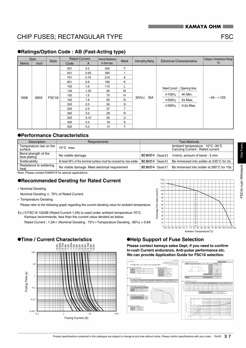
FS
C/In
-rus
hW
ithst
and
Chi
pF
uses
37Product specifications contained in this catalogue are subject to change at any time without notice. Please confirm specifications with your order. 【RoHS】
CHIP FUSES; RECTANGULAR TYPE FSC
KAMAYA OHM
1608 0603 FSC16
StyleSize
InchMetricElectrical Characteristics
CodeRated Current
A
32Vd.c. 35A �55��125
Interrupting Rating
100% 4h Min.
200% 5s Max.
300% 0.2s Max.
MarkCategory Temperature Range
°CInternal Resistance
m ohm max.
Rated Current Opening time
75°C max.
Description Requirements
No visible damage
Solderability
No visible damage. Meet electrical requirement
At least 95% of the terminal surface must be covered by new solder
Bend strength of theface plating
Temperature rise on thesurface
Resistance to solderingheat
Clause 8.3 1mm/s, amount of bend : 3 mm
Clause 8.5 Be immersed into solder at 235°C for 2s.
Clause 8.7 Be immersed into solder at 260°C for 10s.
Ambient temperature : 10°C~30°CCarrying Current : Rated current
Test Methods
Note. Please contact KAMAYA for special applications.
IEC 60127-4
IEC 60127-4
IEC 60127-4
•Recommended Derating for Rated Current
� Nominal Derating
Nominal Derating � 75% of Rated Current
� Temperature Derating
Please refer to the following graph regarding the current derating value for ambient temperature.
Ex.) If FSC16 102AB (Rated Current 1.0A) is used under ambient temperature 70°C,Kamaya recommends, less than the current value derated as below,
Rated Current : 1.0A (Nominal Derating : 75%Temperature Derating : 80%) = 0.6A0
10
20
30
40
50
60
70
80
90
100
110
120
130
-60 -50 -40 -30 -20 -10 0 10 20 30 40 50 60 70 80 90 100110120130
Ambient Temperature(°C)
Perc
enta
ge o
f the
rate
d cu
rrent
(%)
•Time / Current Characteristics
501
631
751
801
102
132
152
162
202
252
302
322
402
502
F
I
A
K
L
M
H
N
S
T
R
U
X
Y
0.5
0.63
0.75
0.8
1.0
1.25
1.5
1.6
2.0
2.5
3.0
3.15
4.0
5.0
400
300
210
180
115
90
70
60
50
37
28
26
18
14
Fusing Current (A)
Fus
ing
Tim
e (s
)
0.001
0.01
0.1
1
10
100
0.1 1 10010
0.5A
0.63
A0.
75A
0.8A
1.0A
1.25
A1.
5A1.
6A2.
0A2.
5A3.
0A3.
15A
4.0A
5.0A
•Ratings/Option Code : AB (Fast-Acting type)
•Performance Characteristics
•Help Support of Fuse SelectionPlease contact kamaya sales Dept, if you need to confirm In-rush Current endurance, Anti-pulse performance etc.We can provide Application Guide for FSC16 selection.
Messrs ***
Series FSC 15 V d.c.Size 1608 (mm) 20 A
OP Code AB Nominal 0.7 A Max.Ambient 70 deg.C MaxAbnormal 4 A
Size Amp. Fusing1608 1.25 A 200%, 5s 32Vd.c. 35A
Condition Spec JudgmentVoltage 15Vd.c. 32Vd.c. OKCurrent 20A 35A OK
70%80%
#1 1.00A Min.#2 2.00A Max.
FSC16 132AB Standing Pulse 100k times
Nominal DeratingTemperature Derating
Application
P/N Interrupting Note.
Verification of Chip Fuse Application■Item for examination
■Item for recommend
■Confirmation for Interrupting
■Confirmation for Derating
■Basis of selection
Operating condition
**/**/20**Kamaya Electric Co., Ltd.Hokkaido Research Center
No.HR2TGF05******
Im
0 t1 t2 t3
1#1 0 - 0.00002 s
Im 10 A
t1 5 ust2 10 ust3 20 us
0 s
1000A^2 * us
Amount
Size Current Fusing#1 FSC 16 132 AB 1608 1.25A 200%, 5s#2#3#4#5
Recommended Item FSC16 132AB
Standing Pulse 100k times
Joule Integral
Items Note
Num of wave
Trapezoidal waveform
Joule Integral
■Confirmations for Rush
■Confirmation of Rush
0
10
20
30
40
50
60
70
80
90
100
110
120
130
-60 -50 -40 -30 -20 -10 0 10 20 30 40 50 60 70 80 90 100110120130
Ambient Temperature(°C)
Perc
enta
ge o
f the
rate
d cu
rrent
(%)
Time t (s)
Joule Integral I2t (A^2s)
FSC16132AB
Your Waveform
0.00001
0.0001
0.001
0.01
0.1
1
0.000001 0.00001 0.0001 0.001 0.01

FLC
/Low
-rat
ioF
usin
gC
hip
Fus
es
38 Product specifications contained in this catalogue are subject to change at any time without notice. Please confirm specifications with your order. 【RoHS】
Unit : mm
*Values for reference
Code Clearing TimeAF
Rated Current
Option Code
KAMAYA OHM
FLC/Low-ratio FusingCHIP FUSES; RECTANGULAR TYPE
e.g. :102=1.0A 132=1.25A 202=2.0A
•Part Number DescriptionExample
•Dimension
L
c c
W
d d
FLC16 0.3�0.15 0.3�0.11608
Style WL
0.45�0.101.6�0.1
Metric
0603
Inch H c d *Unit weight/pc.
2mg
Current value is marked on the cover coating.Please refer to Ratings table on next page.
•Features1. Low-ratio fusing.
·Rated Current 140% fusing (120s Typical.)
2. Certified UL, and c-UL.
·File No. : E176847
3.Major application
•PC related equipment and peripherals (PC, Hard Drive, Printer etc.).
•Small portable devices (Mobile phone, PDA Battery Charger etc.).
•Digital Camera (Digital still camera).
•Game equipment.
•LCD monitors, LCD modules.
•Battery pack.
Rated Current 160% 5s max.
3digit
H
�0.15�0.050.8
FLC 16
Product Type
Style
102 AF TP
FLC
L
L
LL
L
L
L
Bulk (Loose Package)* Packing & Standard Qty. (Min.)
BPaper Tape
1,000pcs.5,000pcs.TP
*Refer to Tape and Packaging information on pages 48 and 49.
Code Metric InchSize
16 1608 0603
USC
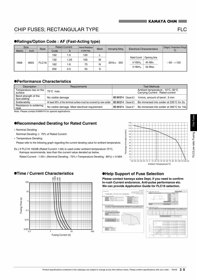
FLC
/Low
-rat
ioF
usin
gC
hip
Fus
es
39Product specifications contained in this catalogue are subject to change at any time without notice. Please confirm specifications with your order. 【RoHS】
CHIP FUSES; RECTANGULAR TYPE FLC
KAMAYA OHM
102
132
162
202
L
M
N
S
1.0
1.25
1.6
2.0
120
100
75
55
1608 0603 FLC16
StyleSize
InchMetricElectrical Characteristics
CodeRated Current
A
32Vd.c. 35A �55��125
Interrupting Rating
100% 4h Min.
160% 5s Max.
MarkCategory Temperature Range
°CInternal Resistance
m ohm max.
Rated Current Opening time
75°C max.
Description Requirements
No visible damage
Solderability
No visible damage. Meet electrical requirement
At least 95% of the terminal surface must be covered by new solder
Bend strength of theface plating
Temperature rise on thesurface
Resistance to solderingheat
Clause 8.3 1mm/s, amount of bend : 3 mm
Clause 8.5 Be immersed into solder at 235°C for 2s.
Clause 8.7 Be immersed into solder at 260°C for 10s.
Ambient temperature : 10°C~30°CCarrying Current : Rated current
Test Methods
IEC 60127-4
IEC 60127-4
IEC 60127-4
Fusing Current (A)
Fus
ing
Tim
e (s
)
•Recommended Derating for Rated Current
� Nominal Derating
Nominal Derating � 70% of Rated Current
� Temperature Derating
Please refer to the following graph regarding the current derating value for ambient temperature.
Ex.) If FLC16 102AB (Rated Current 1.0A) is used under ambient temperature 70°C,Kamaya recommends, less than the current value derated as below,
Rated Current : 1.0A (Nominal Derating : 70%Temperature Derating : 80%) = 0.56A0
10
20
30
40
50
60
70
80
90
100
110
120
130
-60 -50 -40 -30 -20 -10 0 10 20 30 40 50 60 70 80 90 100110120130
Ambient Temperature(°C)
Perc
enta
ge o
f the
rate
d cu
rrent
(%)
•Time / Current Characteristics
0.001
0.01
0.1
1
10
100
1.0A
2.0A
1.25
A1.
6A
1 10 1000.1
•Ratings/Option Code : AF (Fast-Acting type)
Note. Please contact KAMAYA for special applications.
•Performance Characteristics
•Help Support of Fuse SelectionPlease contact kamaya sales Dept, if you need to confirm In-rush Current endurance, Anti-pulse performance etc.We can provide Application Guide for FLC16 selection.
Messrs ***
Series FLC 15 V d.c.Size 1608 (mm) 20 A
OP Code AB Nominal 0.7 A Max.Ambient 70 deg.C MaxAbnormal 4 A
Size Amp. Fusing1608 1.25 A 160%, 5s 32Vd.c. 35A
Condition Spec JudgmentVoltage 15Vd.c. 32Vd.c. OKCurrent 20A 35A OK
70%80%
#1 1.25A Min.#2 2.5A Max.
FLC16 132AB Standing Pulse 100k times
Nominal DeratingTemperature Derating
Application
P/N Interrupting Note.
Verification of Chip Fuse Application■Item for examination
■Item for recommend
■Confirmation for Interrupting
■Confirmation for Derating
■Basis of selection
Operating condition
**/**/20**Kamaya Electric Co., Ltd.Hokkaido Research Center
No.HR2TGF05******
Im
0 t1 t2 t3
1#1 0 - 0.00002 s
Im 10 A
t1 5 ust2 10 ust3 20 us
0 s
tau ms1000A^2 * us
Amount
Size Current Fusing#1 FLC 16 132 AF 1608 160%, 5s#2#3#4#5
Recommended Item FLC16 132AB
Standing Pulse 100k times
Joule Integral
Items Note
Num of wave
Trapezoidal waveform
Joule Integral
■Confirmations for Rush
■Confirmation of Rush
0
10
20
30
40
50
60
70
80
90
100
110
120
130
-60 -50 -40 -30 -20 -10 0 10 20 30 40 50 60 70 80 90 100110120130
Ambient Temperature(°C)
Perc
enta
ge o
f the
rate
d cu
rrent
(%)
Time t (s)
Joule Integral I2t (A^2s)
FLC16132AF
Your Waveform
0.00001
0.0001
0.001
0.01
0.1
1
0.000001 0.00001 0.0001 0.001 0.01
1.25 A

FR
CC
hip
Fus
ible
Res
isto
rs
40 Product specifications contained in this catalogue are subject to change at any time without notice. Please confirm specifications with your order. 【RoHS】
•Features1. No flame, No smoke in overload conditions.
2. Suitable for Battery circuit and Power supply circuit.
Rated resistance value is marked with 3-digit on the over coating
Bulk (Loose Package)* Packing & Standard Qty. (Min.)
BPaper Tape
1,000pcs.5,000pcs.TP
*Refer to Tape and Packaging information on pages 48 and 49.
KAMAYA OHM
FRCCHIP FUSIBLE RESISTORS ; RECTANGULAR TYPE
•Part Number DescriptionExample
•Dimension
L
c c
W
d d
FRC32 1.6 �0.151.25�0.10
0.5�0.25FRC20 0.4�0.2 0.4�0.2
0.5�0.2520123216
WL
0.6 �0.10.6 �0.1
2.0�0.13.2�0.2
08051206
H c d
6mg0.8FRC16 0.3�0.1 0.3�0.1 1608 0.45�0.101.6�0.10603 2.2mg
10mg
Tolerance on Rated ResistanceJ �5%
Rated Dissipation
Rated Resistance
2A 0.1W 1J 0.063W
2B
Size
2016
32 0.125W
E24seriesex.:100=10�
Fusing CharacteristicsC standard
H
FRC 20
Product Type
C 2A 100 J
Style
TP
�0.15�0.05
Unit : mm
*Values for reference
Style Metric Inch *Unit weight/pc.
Code Metric InchSize
16 1608
32 321620 2012
0603
12060805

FR
CC
hip
Fus
ible
Res
isto
rs
41Product specifications contained in this catalogue are subject to change at any time without notice. Please confirm specifications with your order. 【RoHS】
KAMAYA OHM
100
0-55 0 12570
FRC20
FRC32
0.1
2.5W
2.0W
FRC16 0.063 3.9��51� 1.89W
�55��12550V30s max.1��51�
�1,000J(�5%) E24
0.125
FRC20 FRC32FRC16
•Derating CurveThe derated values of dissipation for temperatures in excess of70°C shall be indicated by the following Curve.
1000
100
0.1
0.01
0.001
0.0001
10
1
0 1 2 3 4 5
100
10
0.01
0.001
0.0001
1
0.1
0 1 2 3 4 5
1608(0603)
2012(0805)
3216(1206)
Perc
enta
ge o
f the
rate
d di
ssip
atio
n(%
)
Area of recommended operation
Ambient Temperature(°C)
Size
(Inch)Metric
CHIP FUSIBLE RESISTORS; RECTANGULAR TYPE FRC
1000
100
0.1
0.01
0.001
0.0001
10
1
0 1 2 3 4 5
5.5 clause
∆R≤±5%No major visible damage
∆R≤±5%No major visible damage
Description RequirementsResistance Within specified tolerance 5.1 clause
See Ratings Table
Overload
6.4 clause∆R≤±3%
7.4 clause
∆R≤±5%No major visible damage
5.2 clause
∆R≤±5%No major visible damage
Test Method JIS C5202-1990
7.10 clause
7.9 clause
Rated voltage ×2.5, 5s
Dip into 260°C Solder bath for 10s.
5 cycle between −55°C and +125°C.
Room temp. and 100°C above.
Rated voltage, 1.5h "ON", 0.5h "OFF", 70°C,1,000h.
Rated voltage, 1.5h "ON", 0.5h "OFF", 40°C,95%R.H., 1,000h.
Temperature characteristicof resistance
Resistance to solderingheat
Rapid change oftemperature
Endurance in humidity
Endurance at 70°C
Rated Resistance : 10 ohm Rated Resistance : 1 ohm Rated Resistance : 51 ohm
Power (W)
Fus
ing
Tim
e (s
)
Power (W)
Fus
ing
Tim
e (s
)
Power (W)
Fus
ing
Tim
e (s
)
Style Rated DissipationW
Rated ResistanceRange
Fusing Characteristic
Applied Power Fusing Time
Category TemperatureRange
°C
Maximumopen-circuit
voltage
Tolerance onRated Resistance
Temperature Coefficientof Resistance
10-6/°C
Preferred NumberSeries forResistors
Note1. Rated Voltage = (Rated Dissipation)×(Rated Resistance). (d.c. or a.c. r.m.s. Voltage)Note2. Contact us for further information on other style, resistance and pre-arcing time-current characteristic than those mentioned above.Note3. Contact us for information when inrush and surge voltage are supposed to be applied.Note4. Maximum open circuit voltage is the value of voltage applicable to both ends of resistors,when a resister is open condition in a circuit.
This voltage shall be corresponding to 1,000 times the rated dissipation or maximum open circuit which is the less severe.
•Ratings
•Performance Characteristics
•Example of Typical Fusing Characteristics

RA
C10
1AC
hip
Atte
nuat
ors
42 Product specifications contained in this catalogue are subject to change at any time without notice. Please confirm specifications with your order. 【RoHS】
KAMAYA OHM
RAC101ACHIP ATTENUATORS
•Dimensions and Circuits
Q
*Unit weight/pc.*PaQHWLStyle b
�0.05�0.10 0.65 1.1mg0.15�0.100.33�0.10 1.0�0.05 1.0�0.05
Terminal Style
CRAC101A 0.35�0.05 0.25
P
H
W
a
L
1 2
4 34 3
1 2
b
THRAC 10 1 C1 A
Product Type
•Part Number DescriptionExample
Style
•Features1. Suitable for use at DC and up to UHF band frequencies.
2. 75 ohm is available upon request.
3. Replaceable three discrete resistors with one chip on attenuation
circuits.
Dot mark on Termination 1Attenuation factor on Termination 2 to 3
Unbalanced Type
Circuits
* Packaging & Standard Qty. (Min.)Bulk (Loose Package)BPaper Tape (2 mm pitch)
1,000pcs.10,000pcs.TH
Terminal StyleC With cornerConvex Type
CircuitsA Unbalanced πType
Characteristic Impedance1 50 ohm
Size10 W:1.0mm
*Refer to Tape and Packaging information on pages 48 and 49.
0X1Y23456789ABCDEFGHJKL
0dB0.5dB
1dB1.5dB
2dB3dB4dB5dB6dB7dB8dB9dB
10dB11dB12dB13dB14dB15dB16dB17dB18dB19dB20dB
Attenuation Factor
Unit : mm
*Values for reference

RA
C10
1AC
hip
Atte
nuat
ors
43Product specifications contained in this catalogue are subject to change at any time without notice. Please confirm specifications with your order. 【RoHS】
CHIP ATTENUATORS RAC101A
KAMAYA OHM
•Ratings
Note. The following information is available.1. Test methods for Attenuation Factor and VSWR characteristics.
•Performance Characteristics JIS C 5201-1 : 1998
DescriptionRequirements
3dB∼5dB0.5∼2dB 6dB∼20dB
Characteristicimpedance 50 ohm
Resistance to solderingheat
Within ±0.2dBWithin ±0.1dB Within ±0.3dB
No major visible damage.
Within ±0.2dBWithin ±0.1dB Within ±0.3dB
No major visible damage.
Solderability
50Vd.c., 60sInsulation resistance
Clause 4.17
At least 100M ohm
Rapid change oftemperature
Within ±0.2dBWithin ±0.1dB Within ±0.3dBEndurance at 85˚C
Bend strength of theface plating
Test Methods
MeasuringCircuits
Within ±0.2dBWithin ±0.1dB Within ±0.3dB
R1
1 2
4 3
R2 R2 RL RL=50 ohm
Dip into 235°C Solder bath for 2s.
Clause 4.18 Dip into 260°C Solder bath for 5s.
Clause 4.19 5 cycles between −55°C and +125°C.
Clause 4.25.1 Rated input power, 1.5h"ON", 0.5h"OFF", 85°C, 1,000h.
Clause 4.33 Amount of bend : 3 mm
In accordance with Clause 4.17.4.5
RAC101A
00.51
1.5234567891011121314151617181920
0X1Y23456789ABCDEFGHJKL
- -
�0.3
�0.1 - -
�0.4
�0.8
�1.0
�1.5
�2.0
�2.5
Style CharacteristicImpedance
FrequencyRange
Voltage StandingWave Ratio
Rated Input PowermW/package
Attenuation FactorTolerance on Attenuation
FactordB
Category TemperatureRange
°C
50 ohm
1.1max.
1.2max.DC ≤f ≤3GHz
100 –40~+125
dBsymbol
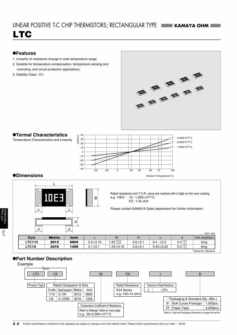
LTC
LPT
Chi
pT
herm
isto
rs
44 Product specifications contained in this catalogue are subject to change at any time without notice. Please confirm specifications with your order. 【RoHS】
W
d d
L
c c
H
•Part Number DescriptionExample
B
KAMAYA OHM
LTC
•Dimensions
LINEAR POSITIVE T-C CHIP THERMISTORS; RECTANGULAR TYPE
30
•Termal CharacteristicsTemperature Characteristics and Linearity
Ambient Temperature(°C)
0
−40
−30
−20
−10
10
20
30
40
1006040250−20−40 75
∆R
/R(%
)
Unit : mm
*Values for reference
1.55�0.103.1�0.1 0.6�0.1 0.45�0.20LTC1/8LTC1/10 2.0�0.15 0.6�0.1 0.4 �0.2 2012
3216
�0.2�0.1
Style WLMetric08051206
Inch H c5mg9mg
d *Unit weight/pc.0.3
�0.2�0.10.3
�0.10�0.051.25
4,500X10-6/°C
3,000X10-6/°C
1,000X10-6/°C
J102LTC 1/8
Product Type
Style
•Features1. Linearity of resistance change in wide temperature range.
2. Suitable for temperature compensation, temperature sensing and
controling, and circuit protection applications.
3. Stability Class : 5%
Rated resistance and T.C.R. value are marked with 4-digit on the over coating.e.g. 10E3...
Please contact KAMAYA Sales department for further information.
10 : 1,000×10-6/°CE3 : 1.5k ohm
Rated Dissipation & SizeCode1/10 0.1W 2012
32161/8 0.125W
Rated Dissipation Metric08051206
Inch
Temperature Coefficient of Resistance
Refer to Ratings Table on next pagee.g.: 30=3,000×10-6/°C
Rated Resistance
E24 Seriese.g.:102=1k ohm
Tolerance on Rated ResistanceJ �5%
* Packaging & Standard Qty. (Min.)Bulk (Loose Package)BPaper Tape
1,000pcs.5,000pcs.TP
*Refer to Tape and Packaging information on pages 48 and 49.
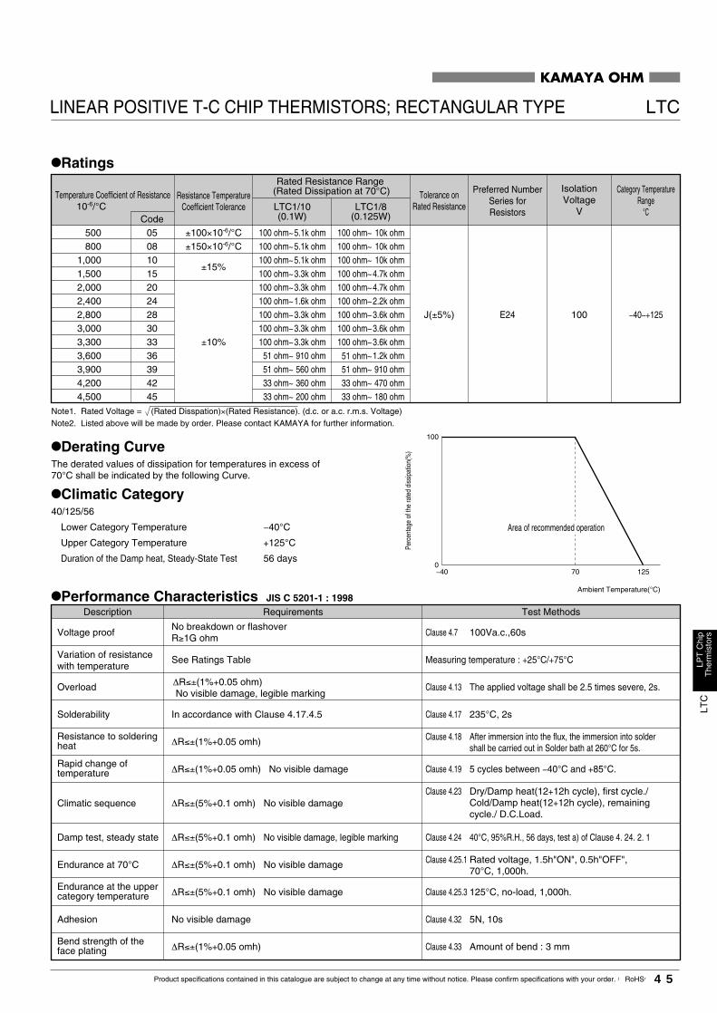
LTC
LPT
Chi
pT
herm
isto
rs
45Product specifications contained in this catalogue are subject to change at any time without notice. Please confirm specifications with your order. 【RoHS】
KAMAYA OHM
LINEAR POSITIVE T-C CHIP THERMISTORS; RECTANGULAR TYPE LTC
•Ratings
500 05
Temperature Coefficient of Resistance10-6/°C
CodeLTC1/10(0.1W)
LTC1/8(0.125W)
±100×10-6/°C
Tolerance onRated Resistance
Preferred NumberSeries forResistors
J(±5%)
Resistance TemperatureCoefficient Tolerance
100 ohm∼5.1k ohm 100 ohm∼ 10k ohm800 08 ±150×10-6/°C 100 ohm∼5.1k ohm 100 ohm∼ 10k ohm
1,000 10±15%
100 ohm∼5.1k ohm 100 ohm∼ 10k ohm1,500 15 100 ohm∼3.3k ohm 100 ohm∼4.7k ohm2,000 20
±10%
100 ohm∼3.3k ohm 100 ohm∼4.7k ohm2,400 24 100 ohm∼1.6k ohm 100 ohm∼2.2k ohm2,800 28 100 ohm∼3.3k ohm 100 ohm∼3.6k ohm3,000 30 100 ohm∼3.3k ohm 100 ohm∼3.6k ohm3,300 33 100 ohm∼3.3k ohm 100 ohm∼3.6k ohm3,600 36 51 ohm∼ 910 ohm 1.2k ohm3,900 39 51 ohm∼ 560 ohm 51 ohm∼
51 ohm∼910 ohm
4,200 42 33 ohm∼ 360 ohm 33 ohm∼ 470 ohm4,500 45 33 ohm∼ 200 ohm 33 ohm∼ 180 ohm
Rated Resistance Range (Rated Dissipation at 70°C)
E24
IsolationVoltage
V
Category TemperatureRange
°C
100 −40∼+125
Ambient Temperature(°C)
100
0−40 12570
Note1. Rated Voltage = (Rated Disspation)×(Rated Resistance). (d.c. or a.c. r.m.s. Voltage)Note2. Listed above will be made by order. Please contact KAMAYA for further information.
•Derating CurveThe derated values of dissipation for temperatures in excess of70°C shall be indicated by the following Curve.
•Climatic Category40/125/56
Lower Category Temperature −40°C
Upper Category Temperature +125°C
Duration of the Damp heat, Steady-State Test 56 days
Perc
enta
ge o
f the
rate
d di
ssip
atio
n(%
)
Area of recommended operation
•Performance Characteristics JIS C 5201-1 : 1998Description Requirements Test Methods
Clause 4.7
Clause 4.13
Clause 4.23
Clause 4.25.1
Clause 4.17
Clause 4.18
Clause 4.19
Clause 4.25.3
Clause 4.32
Clause 4.33
100Va.c.,60s
The applied voltage shall be 2.5 times severe, 2s.
Rated voltage, 1.5h"ON", 0.5h"OFF",70°C, 1,000h.
Measuring temperature : +25°C/+75°C
235°C, 2s
After immersion into the flux, the immersion into soldershall be carried out in Solder bath at 260°C for 5s.
5 cycles between −40°C and +85°C.
125°C, no-load, 1,000h.
5N, 10s
Amount of bend : 3 mmBend strength of theface plating
Voltage proof
Overload
Climatic sequence
Endurance at 70°C
Variation of resistancewith temperature
Solderability
Resistance to solderingheat
Rapid change oftemperature
Damp test, steady state
Endurance at the uppercategory temperature
Adhesion
No breakdown or flashoverR≥1G ohm
∆R≤±(1%+0.05 ohm)No visible damage, legible marking
∆R≤±(5%+0.1 omh) No visible damage
∆R≤±(5%+0.1 omh) No visible damage
See Ratings Table
In accordance with Clause 4.17.4.5
∆R≤±(1%+0.05 omh)
∆R≤±(1%+0.05 omh) No visible damage
∆R≤±(5%+0.1 omh) No visible damage, legible marking
∆R≤±(5%+0.1 omh) No visible damage
No visible damage
∆R≤±(1%+0.05 omh)
Dry/Damp heat(12+12h cycle), first cycle./Cold/Damp heat(12+12h cycle), remainingcycle./ D.C.Load.
Clause 4.24 40°C, 95%R.H., 56 days, test a) of Clause 4. 24. 2. 1

RECO
MM
ENDE
DLA
NDPA
TTER
NIn
form
atio
n
46 Product specifications contained in this catalogue are subject to change at any time without notice. Please confirm specifications with your order. 【RoHS】
•Others(1) Please contact Kamaya Sales Dept. for other products and further details.
(2) Please carry out an enough mounting evaluation when use these patterns.
Size Flow soldering Reflow soldering
Metric Inch A B X Y A B X Y
040206031005160820123216322550256332
0100502010402060308051206121020102512
1.01.32.22.23.95.2
2.63.14.34.36.37.6
0.81.251.62.52.53.2
Not applied
0.80.91.051.051.21.2
0.180.30.51.01.32.22.23.95.2
0.580.91.32.02.73.93.95.97.2
0.20.30.50.81.251.62.52.53.2
0.20.30.40.50.7
0.850.851.01.0
Flow soldering Reflow solderingLand pattern
A A
1
21234
Style
RAC10 2DRAC10 1ARAC10 4DRAC16 2DRAC16 4DRAC16 8URAC16 8D
P
0.65
0.5
0.8
0.64
0.5
Terminals style
C
ACCC
1.0 2.6 0.35 0.45 0.8
B C X Y
Not applied
Not applied
0.5
0.5
1.0
1.01.0
1.3
1.3
2.0
2.02.0
0.34
0.15
0.35
0.320.2
0.33
0.35
0.45
0.320.3
0.4
0.4
0.5
0.50.5
B C X Y
C X
Y
X
YAB
P
Y
X
Y
A
B
P
C X
C X
Y
X
Y
A
B
P Land pattern 1 Land pattern 2
Land pattern 3
•ApplicationAll KAMAYA Surface Mount Devices
Note: This land pattern is not supported by the mounting evaluation.
This is reference information only.
2.Chip network type (No. of terminal: Multiple)
•Recommended land pattern (Reference)1.Square chip type (No. of terminals: 2)
Y
X
Y
A
B
P
C X
Land pattern 4
X
Y AB
KAMAYA OHM
RECOMMENDED LAND PATTERN (SMD TYPE)TECHNICAL GUIDE
Y
※For RLP63, please refer to the page 21.
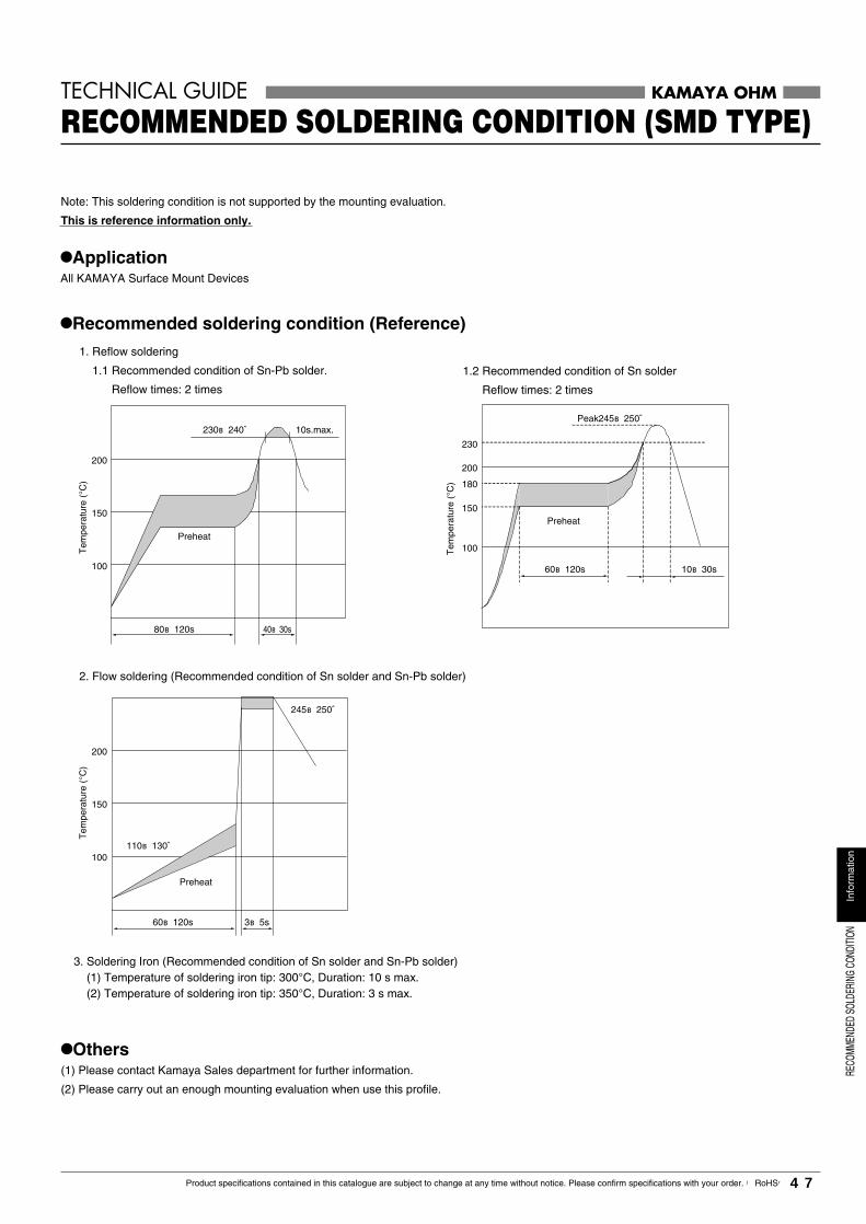
RECO
MMEN
DED
SOLD
ERIN
GCO
NDITI
ONIn
form
atio
n
47Product specifications contained in this catalogue are subject to change at any time without notice. Please confirm specifications with your order. 【RoHS】
1. Reflow soldering
1.1 Recommended condition of Sn-Pb solder.
Reflow times: 2 times
2. Flow soldering (Recommended condition of Sn solder and Sn-Pb solder)
1.2 Recommended condition of Sn solder
Reflow times: 2 times
3. Soldering Iron (Recommended condition of Sn solder and Sn-Pb solder) (1) Temperature of soldering iron tip: 300°C, Duration: 10 s max. (2) Temperature of soldering iron tip: 350°C, Duration: 3 s max.
•Others(1) Please contact Kamaya Sales department for further information.
(2) Please carry out an enough mounting evaluation when use this profile.
Note: This soldering condition is not supported by the mounting evaluation.
This is reference information only.
200
100
230
180
150
200
150
100
80~120s
245~250℃
60~120s 3~5s
110~130℃
Preheat
Preheat
Preheat
230~240℃
Tem
pera
ture
(°C
)T
empe
ratu
re (
°C)
Tem
pera
ture
(°C
)
Peak245~250℃
60~120s 10~30s
10s.max.
40~30s
200
150
100
•ApplicationAll KAMAYA Surface Mount Devices
•Recommended soldering condition (Reference)
KAMAYA OHM
RECOMMENDED SOLDERING CONDITION (SMD TYPE)TECHNICAL GUIDE
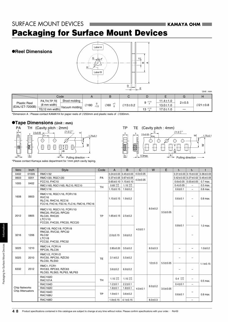
48 Product specifications contained in this catalogue are subject to change at any time without notice. Please confirm specifications with your order. 【RoHS】
Pac
kagi
ngfo
rSur
face
Mou
ntD
evic
esIn
form
atio
n
TE(12 mm width)
Code
�1800
-1.5 �60+10
13 +1.00
A B
�13�0.2
C D
13.0�1.017.0�1.0
E
—
G
�21�0.8
H
PA TH (Cavity pitch : 2mm) (Cavity pitch : 4mm)TP TEt
t1
tC �1.5 +0.1
-02.0±0.05
t1 A
W
E
1.75±0.1
B
C �1.5 +0.1-0t
0.3max.
2.0±0.05
A
W
E 1.75±0.1
B
t
t2
t1
PA,TH,TP,TE(8 mm width)
Shoot molding
Vacuum molding
11.4�1.0 2�0.59 +1.00
KAMAYA OHM
Packaging for Surface Mount DevicesSURFACE MOUNT DEVICES
•Reel Dimensions G
DE
AB
C
H
Label B
Label A
Unit : mm
Plastic Reel(EIAJ ET-7200B)
*Dimension A : Please contact KAMAYA for paper reels of �250mm and plastic reels of �330mm.
*Please contact Kamaya sales department for 1mm pitch cavity taping.
•Tape Dimensions (Unit : mm)
Pulling direction Pulling direction
0.37�0.05
1.15�0.15
1.15�0.15
1.65�0.15
2.0�0.15
2.85�0.20
3.1�0.2
3.6�0.2
1.2�0.1
1.8�0.1
1.9�0.1
0.65
0603 0201
1005 0402TH
TH
TP
TP
TE
RAC104DRAC162D
1608 0603
2012 0805
3216 1206
3225 1210
5025 2010
6332 2512
+0.05–0.10
1.15 +0.05–0.10
0.67�0.05
1.9�0.2
1.9�0.2
2.5�0.2
3.6�0.2
3.5�0.2
5.5�0.2
6.9�0.2
2.2�0.1
1.8�0.1
1.9�0.15RAC168D 4.1�0.15
3.6�0.2
0.42�0.03
0.4�0.050.6�0.1
0.6�0.1
0.8�0.1
–
–
–
0.4�0.1
0.6�0.1
0.27�0.02
––
–
–
–
–
–
–
–
–
–
0.45�0.050.6�0.05 0.55�0.05 0.7 max.
0.5 max.0.8 max.
0.8 max.
1.0 max.
1.0�0.2
1.1�0.15
0.5 max.
0.8 max.
0.65�0.10PA
1.15�0.104.0�0.05
4.0�0.05
4.0�0.1
4.0�0.1
8.0�0.2
8.0�0.3
12�0.3
8.0�0.2
3.5�0.05
5.5�0.05
3.5�0.05
1.15 +0.05–0.10
1.15 +0.05–0.10 0.4 +0.05
–0.10
Metric Inch Style Code A B C W E t1 t2 t
RAC164DRAC168U
Chip NetworksChip Attenuators
RMC1/20, RGC1/20
RMC1/16S, RGC1/16S, RLC10, RCC10
RMC1/16, RGC1/16, FCR1/16RVC16RLC16, RHC16, RCC16FCC16, FHC16, FSC16, FLC16, FMC16, FRC16
RMC1/8, RGC1/8, FCR1/8RNC32, RVC32, RPC32RLC32LTC1/8FCC32, FHC32, FRC32
RMC1/10, RGC1/10, FCR1/10RNC20, RVC20, RPC20RLC20, RHC20LTC1/10FCC20, FHC20, FRC20, RCC20
RMC1/16
RAC102DRAC101A
RMC1/4, FCR1/4RPC35, RLC35
RMC1/2, FCR1/2RVC50, RPC50, RZC50RLC50, RLS50
RMC1, FCR1RVC63, RPC63, RZC63RLC63, RLS63, RLP63, MLP63
FCC10, FHC10
0.24�0.030402 01005 0.45�0.03 0.31�0.03 0.15�0.02 0.36�0.03RMC1/32
8.0�0.3 –
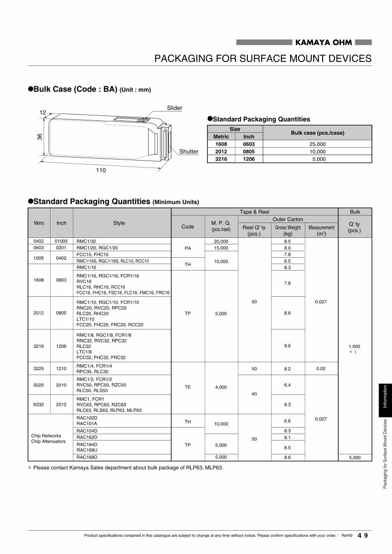
49Product specifications contained in this catalogue are subject to change at any time without notice. Please confirm specifications with your order. 【RoHS】
Info
rmat
ion
Pac
kagi
ngfo
rSur
face
Mou
ntD
evic
es
KAMAYA OHM
PACKAGING FOR SURFACE MOUNT DEVICES
•Bulk Case (Code : BA) (Unit : mm)
110
12
Shutter
Slider
36
•Standard Packaging Quantities
25,000
Bulk case (pcs./case)Size
Metric1608
10,0002012 5,0003216
Inch060308051206
•Standard Packaging Quantities (Minimum Units)
10,000
10,000
5,000
5,000
5,000
4,000
0603 0201
1005 0402
PA
TH
TH
TP
TP
TE
RAC102DRAC101A
RAC104D
RAC168D
RAC162D
RAC164D
RMC1/2, FCR1/2RVC50, RPC50, RZC50RLC50, RLS50
RMC1, FCR1RVC63, RPC63, RZC63RLC63, RLS63, RLP63, MLP63
1608 0603
2012 0805
3216 1206
3225 1210
5025 2010
6332 2512
50
8.0
6.58.3
7.8
7.8
8.6
0.027
1,000※1
0.02
0.027
9.6
8.2
6.4
8.3
6.6
8.3
8.1
5,000
8.5
8.6
40
50
50
Metric Inch StyleCode
M. P. Q.(pcs./reel) Reel Q' ty
(pcs.)Gross Weight
(kg)
Outer CartonTape & Reel Bulk
Measurement(m3)
Q' ty(pcs.)
RAC168U
Chip NetworksChip Attenuators
RMC1/20, RGC1/20
RMC1/16S, RGC1/16S, RLC10, RCC10FCC10, FHC10
RMC1/16, RGC1/16, FCR1/16RVC16RLC16, RHC16, RCC16FCC16, FHC16, FSC16, FLC16, FMC16, FRC16
RMC1/8, RGC1/8, FCR1/8RNC32, RVC32, RPC32RLC32LTC1/8FCC32, FHC32, FRC32
RMC1/10, RGC1/10, FCR1/10RNC20, RVC20, RPC20RLC20, RHC20LTC1/10FCC20, FHC20, FRC20, RCC20
RMC1/16
RMC1/4, FCR1/4RPC35, RLC35
0402 01005 8.515,00020,000RMC1/32
※Please contact Kamaya Sales department about bulk package of RLP63, MLP63.
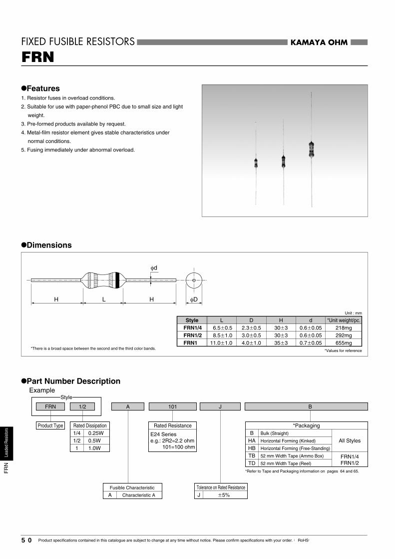
1/41/21
0.5W0.25W
1.0W
FRN 1/2
Style
A J101 B
KAMAYA OHMFIXED FUSIBLE RESISTORS
FRN
•Features1. Resistor fuses in overload conditions.
2. Suitable for use with paper-phenol PBC due to small size and light
weight.
3. Pre-formed products available by request.
4. Metal-film resistor element gives stable characteristics under
normal conditions.
5. Fusing immediately under abnormal overload.
•Dimensions
*There is a broad space between the second and the third color bands.
φd
H HL φD
*Unit weight/pc.
292mg218mg
Unit : mm
655mg
d
0.6�0.050.6�0.05
0.7�0.0530�330�3
35�33.0�0.52.3�0.5
4.0�1.0
DL
8.5�1.06.5�0.5
11.0�1.0
Style
FRN1/2FRN1/4
FRN1
H
*Values for reference
•Part Number DescriptionExample
Product Type
Fusible Characteristic
A Characteristic A
*PackagingB
HA Horizontal Forming (Kinked)
HB Horizontal Forming (Free-Standing)
TB 52 mm Width Tape (Ammo Box)
TD 52 mm Width Tape (Reel)
Bulk (Straight)
All Styles
FRN1/4FRN1/2
Rated Resistance
E24 Seriese.g.: 2R2=2.2 ohm
101=100 ohm
Rated Dissipation
Tolerance on Rated ResistanceJ �5%
*Refer to Tape and Packaging information on pages 64 and 65.
50 Product specifications contained in this catalogue are subject to change at any time without notice. Please confirm specifications with your order. 【RoHS】
Lead
edRe
sisto
rsF
RN

•Performance Characteristics
FRN 1
FRN 1/2
FRN 1/4 0.25
0.5 J (±5%)±300 1.0 ohm~1k ohm E24 –25~+155
1.0
100
0-25 15570
KAMAYA OHM
FIXED FUSIBLE RESISTORS FRN
•Ratings
Style Rated ResistanceRange
Rated Dissipation at 70°C
W
Category TemperatureRange
°C
Perferred NumberSeries
for Resistors
Tolerance onRated Resistance
Temperature Coefficientof Resistance
10-6/°C
Note1. Rated Voltage = (Rated Dissipation) × (Nominal Resistance). (d.c. or a.c. r.m.s. Voltage)
•Derating CurveThe derated values of dissipation for temperatures in excess of70°C shall be indicated by the following Curve.
Ambient Temperature(°C)
Perc
enta
ge o
f the
rate
d di
ssip
atio
n(%
)Area of recommended operation
Description RequirementsResistance Within specified tolerance
At least 95% of the dipping surface must be covered by new solder
Clause 6.4
Clause 6.1.2 (1)
Clause 5.7
OverloadClause 5.5
Clause 5.1
Clause 5.2 Room temperature and 100°C above.
Clause 6.3
Within ±(1.5%+0.05 ohm)No major visible damage
See Ratings Table
Voltage proof No flashover, scorching or insulation breakdown
Pulling
Bending
Lead is not cut, Terminal is not loose
Within ±(1%+0.05 ohm)No mechanical damage
Solderability
Fusingcharacteristic
Clause 6.5
Clause 7.5
Within ±(5%+0.1 ohm)No major visible damage Markings legible
Within ±(5%+0.1 ohm)No major visible damage Markings legible
Within ±(1%+0.05 ohm)No major visible damage Markings legible
Within ±(5%+0.1 ohm)No major visible damage Markings legible
Clause 7.4
Humidity(Normal Condition)
Clause 7.9
Clause 7.10
Using the resistor without turning on electricity as the testing sample at room temperature with no wind, apply a voltage equivalent to the rated dissipation ratio (keep the voltage fixed while testing), and measure the times until the circuit current decreases drastically.
This must melt and cut within the time indicated below without burning or arcing characteristic A 24s at 15 times rated dissipation. But with FRN1/4 R<4.7 ohm. 30s at 15 times rated dissipation.
Vibration
Within ±(1%+0.05 ohm)No major visible damage
Test Method JIS C5202-1990
Clause 6.1.2 (4)
350°C, 2∼2.5mm from the body 3.5s.
FRN1/4,1/2 :10N for 5~10sFRN1 :25N for 5~10s
FRN1/4 :300Va.c., 60sFRN1/2,1 :350Va.c., 60s
Condition ARated Voltage × 2.5, 5s
Type A10∼55Hz, 3 directions, 2h each
235°C, 5s
40°C 90∼95%R.H. 500h.
−25°C/+85°C for 5 cycles.
Rated voltage, 1.5h "ON", 0.5h "OFF",40°C, 95%R.H., 1,000h.
Rated Voltage, 1.5h "ON", 0.5h "OFF",70°C, 1,000h.
5N, 2 times
Note2. Fusing characteristic of constant current circuit is available on your request.Note3. Other fusing characteristic products are also available. Contact KAMAYA for further details.
Temperature characteristicof resistance
Bond strengthof the face plating
Resistance to solderingheat
Rapid change oftemperature
Endurance in humidity
Endurance at 70°C
51Product specifications contained in this catalogue are subject to change at any time without notice. Please confirm specifications with your order. 【RoHS】
Lead
edRe
sisto
rsF
RN
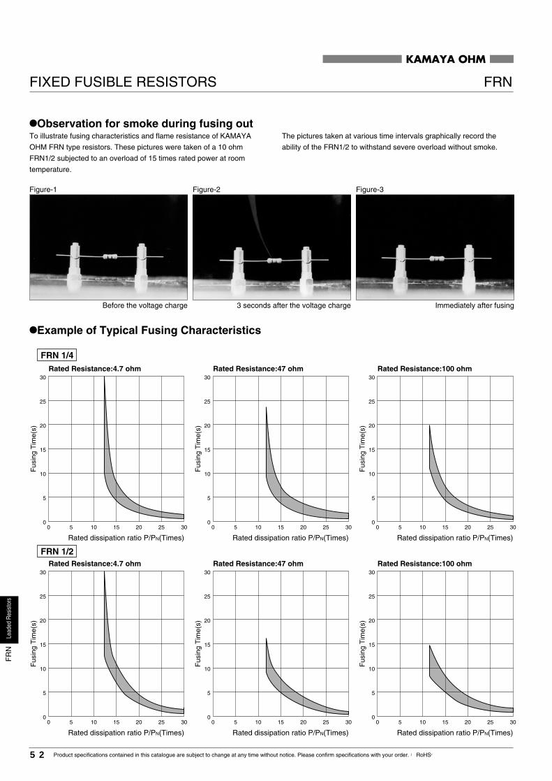
KAMAYA OHM
FIXED FUSIBLE RESISTORS FRN
•Observation for smoke during fusing outTo illustrate fusing characteristics and flame resistance of KAMAYA
OHM FRN type resistors. These pictures were taken of a 10 ohm
FRN1/2 subjected to an overload of 15 times rated power at room
temperature.
The pictures taken at various time intervals graphically record the
ability of the FRN1/2 to withstand severe overload without smoke.
Figure-1 Figure-2 Figure-3
Before the voltage charge 3 seconds after the voltage charge Immediately after fusing
•Example of Typical Fusing Characteristics
FRN 1/4
Fus
ing
Tim
e(s)
Rated Resistance:4.7 ohm
Rated dissipation ratio P/PN(Times)
30
25
20
15
10
5
00 5 10 15 20 25 30
Rated Resistance:4.7 ohm30
25
20
15
10
5
00 5 10 15 20 25 30
Rated dissipation ratio P/PN(Times)
Fus
ing
Tim
e(s)
Rated Resistance:47 ohm30
25
20
15
10
5
00 5 10 15 20 25 30
Rated dissipation ratio P/PN(Times)
Fus
ing
Tim
e(s)
Rated Resistance:100 ohm30
25
20
15
10
5
00 5 10 15 20 25 30
Rated dissipation ratio P/PN(Times)
Fus
ing
Tim
e(s)
Rated Resistance:47 ohm30
25
20
15
10
5
00 5 10 15 20 25 30
Rated dissipation ratio P/PN(Times)
Fus
ing
Tim
e(s)
Rated Resistance:100 ohm30
25
20
15
10
5
00 5 10 15 20 25 30
Rated dissipation ratio P/PN(Times)
Fus
ing
Tim
e(s)
FRN 1/2
52 Product specifications contained in this catalogue are subject to change at any time without notice. Please confirm specifications with your order. 【RoHS】
Lead
edRe
sisto
rsF
RN

KAMAYA OHM
Rated Resistance:4.7 ohm30
25
20
15
10
5
00 5 10 15 20 25 30
Rated dissipation ratio P/PN(Times)
Fus
ing
Tim
e(s)
Rated Resistance:100 ohm30
25
20
15
10
5
00 5 10 15 20 25 30
Rated dissipation ratio P/PN(Times)
Fus
ing
Tim
e(s)
Rated Resistance:47 ohm30
25
20
15
10
5
00 5 10 15 20 25 30
Rated dissipation ratio P/PN(Times)
Fus
ing
Tim
e(s)
FRN 1
FIXED FUSIBLE RESISTORS FRN
53Product specifications contained in this catalogue are subject to change at any time without notice. Please confirm specifications with your order. 【RoHS】
Lead
edRe
sisto
rsF
RN

1 1.0 W
225
0.7�0.1 4.0�1.06.0min.RNV 1dH
37�2DL2L1
+1.0–1.512.0 703mg
RNV 1 J B
Style
KAMAYA OHMFIXED HIGH VOLTAGE RESISTORS
RNV
•Features1. High maximum working voltage, excellent for surge applications.
2. IEC Publ. 65 applies to RNV1.
3. Approved to UL, c-UL, BSI and VDE standards.
•UL, c-UL, File No. E151897
510k ohm~910k ohm : 125V max.
960k ohm~11M ohm : 250V max.
•BSI No.7778
BS EN 60065:1994 (BS 415:1994) : Sub-clauses 9.3.5,14.1
(a) and (b)
•VDE No.VDE-Reg.-Nr.10149
DIN EN VDE (EN 60065:1994-04,14.1a)
4. Stability Class : 5%
•Dimensions
L2 : distance between inner caps
*Unit Weight/pc.Unit : mm
Style
*Value for Reference
•Part Number DescriptionExample
Product Type *PackagingB
TD
H
52 mm Width Tape (Ammo Box)TB52 mm Width Tape (Reel)
Bulk (Straight)Horizontal Forming
HB Horizontal Forming (Free-Standing)
Tolerance on Rated ResistanceRated Resistance
E24, 12 Seriese.g. : 225=2.2M ohm
*Refer to Tape and Packaging information on pages 64 and 65.Some code numbers may be added after packing codes.
J �5%
VDEBSITL5USC
φDH HL1
L2 φd
Rated Dissipation
54 Product specifications contained in this catalogue are subject to change at any time without notice. Please confirm specifications with your order. 【RoHS】
Lead
edRe
sisto
rsR
NV
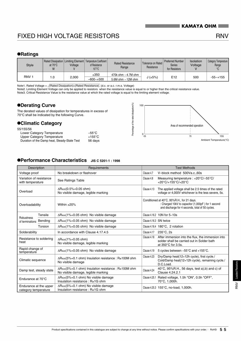
~J (±5%)
100
0-55 15570
RNV 1±350
2,0001.0–600~+500 ~
470k ohm5.6M ohm
4.7M ohm12M ohm
E12 500 -55~+155
KAMAYA OHM
FIXED HIGH VOLTAGE RESISTORS RNV
•Ratings
StyleRated Dissipation
at 70°CW
Limiting ElementVoltage
V
Rated ResistanceRange
Tolerance on RatedResistance
Preferred NumberSeries
for Resistors
IsolationVoltage
V
Category TemperatureRange
°C
Temperature Coefficientof Resistance
10-6/°C
Note1. Rated Voltage = (Rated Dissipation)×(Rated Resistance). (d.c. or a.c. r.m.s. Voltage)Note2. Limiting Element Voltage can only be applied to resistors when the resistance value is equal to or higher than the critical resistance value.Note3. Critical Resistance Value is the resistance value at which the rated voltage is equal to the limiting element voltage.
•Derating CurveThe derated values of dissipation for temperatures in excess of70°C shall be indicated by the following Curve.
•Climatic Category55/155/56
Lower Category Temperature −55°CUpper Category Temperature +155°CDuration of the Damp heat, Steady-State Test 56 days Ambient Temperature(°C)
Perc
enta
ge o
f the
rate
d di
ssip
atio
n(%
)
Area of recommended operation
•Performance Characteristics JIS C 5201-1 : 1998
Description Requirements Test Methods
Clause 4.7
Clause 4.13
Clause 4.23
Clause 4.25.1
Clause 4.8
Clause 4.17
Clause 4.18
Clause 4.19
Clause 4.24
Clause 4.25.3
V–block method 500Va.c.,60s
The applied voltage shall be 2.5 times of the ratedvoltage or 4,000V whichever is the less severe, 5s.
Clause 4.16.2 10N for 5∼10s
Clause 4.16.4 180°C, 2 rotation
Rated voltage, 1.5h "ON", 0.5h "OFF",70°C, 1,000h.
Measuring temperature : +20°C/−55°C/+20°C/+155°C/+20°C
235°C, 2s
After immersion into the flux, the immersion intosolder shall be carried out in Solder bathat 350°C for 3.5s.
5 cycles between −55°C and +155°C.
40°C, 95%R.H., 56 days, test a),b) and c) ofClause 4.24.2.1
155°C, no-load, 1,000h.
Voltage proof
Overload
Robustnessof terminations
Tensile
Torsion
Clause 4.16.3 5N twiceBending
Climatic sequence
Endurance at 70°C
Variation of resistancewith temperature
Solderability
Resistance to solderingheat
Rapid change oftemperature
Damp test, steady state
Endurance at the uppercategory temperature
No breakdown or flashover
See Ratings Table
∆R≤±(0.5%+0.05 ohm)No visible damage, legible marking
Conditioned at 40°C, 95%R.H., for 21 days. : Charged 10kV to capacitor (1,000pF ) for 1 second
and discharge for 4 seconds, total of 50 cycles.Overloadability Within ±20%
∆R≤±(1%+0.05 ohm) No visible damage
∆R≤±(1%+0.05 ohm) No visible damage
∆R≤±(1%+0.05 ohm) No visible damage
In accordance with Clause 4.17.4.5
∆R≤±(1%+0.05 ohm)No visible damage, legible marking
∆R≤±(1%+0.05 ohm) No visible damage
∆R≤±(5%+0.1 ohm) Insulation resistance : R≥100M ohmNo visible damage
∆R≤±(5%+0.1 ohm) No visible damageInsulation resistance : R≥1G ohm∆R≤±(5%+0.1 ohm) No visible damageInsulation resistance : R≥1G ohm
∆R≤±(5%+0.1 ohm) Insulation resistance : R≥100M ohmNo visible damage, legible marking
Dry/Damp heat(12+12h cycle), first cycle./Cold/Damp heat(12+12h cycle), remaining cycle./D.C.Load.
55Product specifications contained in this catalogue are subject to change at any time without notice. Please confirm specifications with your order. 【RoHS】
Lead
edRe
sisto
rsR
NV

RC 1/2U 685 M B
Style
1/2U 0.5W
KAMAYA OHM
RC1/2UFIXED CONDUCTIVE PATH RESISTORS
•Features1. UL recognized component (UL1676) (File No.E151897)
2. Reduce UL or CSA approval and maintenance cost.
3. Color band 5 is green signify UL 1676 approval and distinguishes
from standard resistors.
4. Stability Class : 10%
•Dimensions
φd
L φDHH
Unit : mm
RC1/2U 3.6�0.2Style L D
28�3 422mg*Unit weight/pc.d
+0.07−0.050.7+0.8
−0.79.5*Value for reference
H
•Part Number DescriptionExample
Product Type
*Refer to Tape and Packaging information on pages 64 and 65.
*Packaging
Horizontal FormingHBulk (straight)B
52 mm Width Tape (Ammo Box)TB
52 mm Width Tape (Reel)TD
Rated Resistance
E12, 6 Seriese.g. : 685=6.8M ohm 106=10M ohm
Rated Dissipation Tolerance on Rated ResistanceK �10%M �20%
USC
※The name of this, product is granted as Conductive Path, but UL1676 and the requirements as Discharge Path shown in CSA22, 2 No,1-94 are satisfied, but the products performance does not cover all the requirements as Conductive Path.
56 Product specifications contained in this catalogue are subject to change at any time without notice. Please confirm specifications with your order. 【RoHS】
Lead
edRe
sisto
rsR
C1/
2U

100
0-55 12570
KAMAYA OHM
FIXED CONDUCTIVE PATH RESISTORS RC1/2U
•Ratings
RC1/2U
Style
1M ohm�10M ohm
K(�10%)E12
M(�20%)E6
250Va.c. max.or
125Va.c. max.500
Rated ResistanceRange
350
RatedVoltage
V
0.5
Rated Dissipation at 70°C
W
Specified LineVoltage
IsolationVoltage
V
�55��125
Category TemperatureRange°C
Tolerance on RatedResistance and
Perferred Number Seriesfor Resistors.
Note1. Required characteristic performance is based on JIS C 6406 and UL 1676.Note2. The name of this, product is granted as Conductive Path, but UL1676 and the requirements as Discharge Path shown in CSA22, 2 No,1-94 are satisfied, but the products performance does not cover all the requirements as Conductive Path.
•StorageTemperature 20�15°C, Humidity 60%R.H. Max, Recommendation Storing Term 6 months after shipped from factory.
•Derating CurveThe derated values of dissipation for temperatures in excess of70°C shall be indicated by the following Curve.
•Climatic Category55/125/56
Lower Category Temperature �55°C
Upper Category Temperature �125°C
Duration of the Damp heat, Steady-State Test 56 days
Ambient Temperature(°C)
Perc
enta
ge o
f the
rate
d di
ssip
atio
n(%
)
Area of recommended operation
•Color Coding
Fifth color band: Green (Symbol of UL approved component)
Fourth color band: Resistance tolerance; K or M (In the case of M: Nil color band)
Third color band(Multiplier)Second color band(Second significant figure) Rated Resistance
First color band(First significant figure)
57Product specifications contained in this catalogue are subject to change at any time without notice. Please confirm specifications with your order. 【RoHS】
Lead
edRe
sisto
rsR
C1/
2U

1/4 0.25W1/2 0.5W
RC 1/4 102 J B
Style
KAMAYA OHMFIXED CARBON COMPOSITION RESISTORS
RC
•Features1. Improved pulse endurance characteristics compared to carbon-film
devices.
2. Wide resistance range is available, 1 ohm ~ 22M ohm.
3. Stability Class : 10%
•Dimensions
0.6 �0.052.4�0.16.3 �0.7RC1/43.6�0.2RC1/2
*Unit weight/pc.
422mg222mg
Unit : mm
d
28�330�3
DLStyle
+0.07−0.050.7+0.8
−0.79.5
φd
H
H HL φD
*Values for reference
•Part Number DescriptionExample
Product Type Rated Resistance
E24, 12, 6 Seriese.g. : 2R2=2.2 ohm 102=1k ohm
*Refer to Tape and Packaging information on pages 64 and 65.
*PackagingBHTB
Horizontal Forming
52 mm Width Tape (Ammo Box)
TD 52 mm Width Tape (Reel)
Bulk (Straight)
Rated DissipationJ �5% K �10%M �20%
Tolerance on Rated Resistance
58 Product specifications contained in this catalogue are subject to change at any time without notice. Please confirm specifications with your order. 【RoHS】
Lead
edRe
sisto
rsR
C
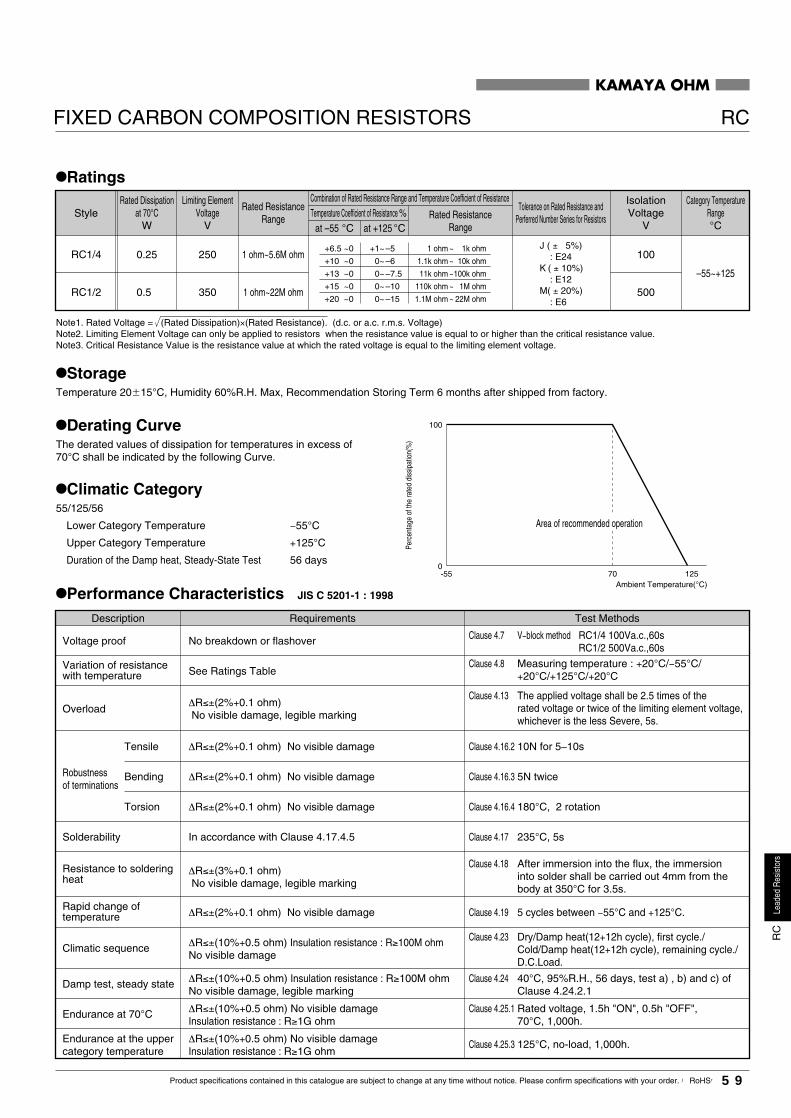
RC1/2
RC1/4
0.5
0.25
500
100
–55~+125
1 ohm~22M ohm
1 ohm~5.6M ohm
350
250J ( ± 5%) : E24K ( ± 10%) : E12 M( ± 20%) : E6
at –55 °C at +125 °C
1 ohm
1.1k ohm
11k ohm
110k ohm
1.1M ohm
~
~
~
~
~
1k ohm
10k ohm
100k ohm
1M ohm
22M ohm
+6.5
+10
+13
+15
+20
~0
~0
~0
~0
~0
+1
0
0
0
0
~
~
~
~
~
–5
–6
–7.5
–10
–15
100
0-55 12570
KAMAYA OHM
FIXED CARBON COMPOSITION RESISTORS RC
StyleRated Dissipation
at 70°CW
Rated ResistanceRange Rated Resistance
Range
Limiting ElementVoltage
V
Tolerance on Rated Resistance andPerferred Number Series for Resistors
Combination of Rated Resistance Range and Temperature Coefficient of Resistance IsolationVoltage
V
Category TemperatureRange°C
•Ratings
Temperature Coefficient of Resistance %
Note1. Rated Voltage = (Rated Dissipation)×(Rated Resistance). (d.c. or a.c. r.m.s. Voltage)Note2. Limiting Element Voltage can only be applied to resistors when the resistance value is equal to or higher than the critical resistance value.Note3. Critical Resistance Value is the resistance value at which the rated voltage is equal to the limiting element voltage.
•Derating CurveThe derated values of dissipation for temperatures in excess of70°C shall be indicated by the following Curve.
•StorageTemperature 20�15°C, Humidity 60%R.H. Max, Recommendation Storing Term 6 months after shipped from factory.
•Climatic Category55/125/56
Lower Category Temperature −55°C
Upper Category Temperature +125°C
Duration of the Damp heat, Steady-State Test 56 days
Ambient Temperature(°C)
Perc
enta
ge o
f the
rate
d di
ssip
atio
n(%
)
Area of recommended operation
•Performance Characteristics JIS C 5201-1 : 1998
Description Requirements Test Methods
Clause 4.13
Clause 4.23
Clause 4.25.1
Clause 4.8
Clause 4.17
Clause 4.18
Clause 4.19
Clause 4.24
Clause 4.25.3
The applied voltage shall be 2.5 times of therated voltage or twice of the limiting element voltage,whichever is the less Severe, 5s.
Clause 4.7
Clause 4.16.2 10N for 5∼10s
Clause 4.16.4 180°C, 2 rotation
Rated voltage, 1.5h "ON", 0.5h "OFF",70°C, 1,000h.
Measuring temperature : +20°C/−55°C/+20°C/+125°C/+20°C
235°C, 5s
After immersion into the flux, the immersioninto solder shall be carried out 4mm from thebody at 350°C for 3.5s.
5 cycles between −55°C and +125°C.
40°C, 95%R.H., 56 days, test a) , b) and c) ofClause 4.24.2.1
125°C, no-load, 1,000h.
Voltage proof
Overload
Robustnessof terminations
Tensile
Torsion
Clause 4.16.3 5N twiceBending
Climatic sequence
Endurance at 70°C
Variation of resistancewith temperature
Solderability
Resistance to solderingheat
Rapid change oftemperature
Damp test, steady state
Endurance at the uppercategory temperature
No breakdown or flashover
See Ratings Table
∆R≤±(2%+0.1 ohm)No visible damage, legible marking
∆R≤±(2%+0.1 ohm) No visible damage
∆R≤±(2%+0.1 ohm) No visible damage
∆R≤±(2%+0.1 ohm) No visible damage
In accordance with Clause 4.17.4.5
∆R≤±(3%+0.1 ohm)No visible damage, legible marking
∆R≤±(2%+0.1 ohm) No visible damage
∆R≤±(10%+0.5 ohm) Insulation resistance : R≥100M ohmNo visible damage
∆R≤±(10%+0.5 ohm) No visible damageInsulation resistance : R≥1G ohm
∆R≤±(10%+0.5 ohm) No visible damageInsulation resistance : R≥1G ohm
∆R≤±(10%+0.5 ohm) Insulation resistance : R≥100M ohmNo visible damage, legible marking
Dry/Damp heat(12+12h cycle), first cycle./Cold/Damp heat(12+12h cycle), remaining cycle./D.C.Load.
RC1/4 100Va.c.,60sRC1/2 500Va.c.,60s
V−block method
59Product specifications contained in this catalogue are subject to change at any time without notice. Please confirm specifications with your order. 【RoHS】
Lead
edRe
sisto
rsR
C

TotalTotal10060200
1.20X10⁷
1.196X10⁷
2.992X10⁶
2.997X10⁶
2.990X10⁶
2.984X10⁶
0153246
0.00550.1250.1000.0670.1340.201
0.0070.1380.1390.1040.1760.244
1.299×10⁷
7.209×10⁵
7.194×10⁵
9.615×10⁵
5.682×10⁵
4.098×10⁵
Criterion(%)
∆R/R�5
Load RatioP/Pn(%)
Total Testing Time T(Hrs. )
Number of Failuresr(pcs.)
Failure Ratio
CL(60%)
Average Lifetime(60% reliability level)
(Hrs.)
�10
•Typical Characteristics
•Surge Resistance Characteristics Charging and discharging a 2,000 pF capacitor for 100 cycles.
"Typical characteristics indicate the mean values of ∆R/R etc."
∆R
/R(%
)
Voltage(kV)
10
0
-20
-30
-10
0 2 4 6 8 10
c
b
a
12 14
RC1/4a : 1.2M ohmb : 33k ohmc : 1k ohm
•Relationship between Load Ratio and Category Temperature
∆R
/R(%
)
Ambient Temperrature(°C)
0
−5
−15
−10
30 50 70 90 110 130
RC1/2 100k ohm n=502,500 hours
∆R
/R(%
)
Voltage(kV)
10
0
−20
−30
−10
0 2 4 6 8 10
c
ba
12 14
RC1/2a : 1.2M ohmb : 10k ohmc : 1k ohm
Load FactorP/Ph=1.251.0 0.75 0.5
0
0.25
•Endurance at 70°C
∆R
/R(%
)
Testing Time(Hrs.)
0
−1
−3
−2
0 100 500 1000
RC1/4
RC1/2220k ohm in anatomosphere of 70°C
•Variation with Time Condition : 5~35°C , 45~85% R.H.
∆R
/R(%
)
Variation with Time(month)
3
2
1
−1
0
20 4 6 8 10 12
a : RC1/4 100k ohmb : RC1/4 1k ohmc : RC1/2 1M ohm
ab
c
•Frequency Characteristics
∆R
ac/R
dc(%
)
(MHz . M ohm)
100
75
25
0
50
0.1 0.5 1 5 10 50 100
a
b
a : RC1/4b : RC1/2
KAMAYA OHM
FIXED CARBON COMPOSITION RESISTORS RC
•Reliability Test Endurance in humidity Samples : RC1/4J,100 ohm,1k ohm,10k ohm,100k ohm×150 each. Total 2,400. Conditions : Direct current voltage equivalent to the following load ratings in cycles on "ON" for 1.5h and "OFF" for 0.5h for a total of 5,000h in an atmosphere of 40°C, 90 to 95%R.H.
60 Product specifications contained in this catalogue are subject to change at any time without notice. Please confirm specifications with your order. 【RoHS】
Lead
edRe
sisto
rsR
C

0.5max. 1.0max. 3.2min.52�126�0.2
Pt
5.0�0.3
W
6.0�0.5
T Z S
Product Type
JW 1 3 H16A
Style
KAMAYA OHM
•Features1. 26 mm and 52 mm available for automatic insertion.
2. Pre-formed product available on request.
JWJUMPER WIRES
•Dimensions
A
W
B
tT
S
PZ
1. Tape 2. Forming
Unit : mm
26 mm Width Tape
52 mm Width Tape
Style
A dimension
5.0
5.0
10.0
12.5
× B dimension
× 2.5
× 5.5
× 15.0
× 2.5
*Please contact KAMAYA for other dimensions.
•RatingsMaximum Rated
Currency(A)Category Temperature
Range(°C)
−55∼+15510
*Packaging
52 mm Width Tape (Ammo Box)TB26 mm Width Tape (Ammo Box)TAForming 12.5×2.5H16EForming 10.0×15.0H14DForming 5.0×5.5H13AForming 5.0×2.5H16A
*Some code numbers may be added after packing codes.
Diaφ0.6mm1
MaterialSn Plated copper3
Example
61Product specifications contained in this catalogue are subject to change at any time without notice. Please confirm specifications with your order. 【RoHS】
Lead
edRe
sisto
rsJW

1.0W12.0W23.0W34.0W46.0W68.0W8
FGJK
� 1%� 2%� 5%�10%
d
0.8
H
38�34.0�1.0
DL
14.5�1.0RH 1
1.038�35.0�1.026.5�1.0RH 2
1.038�35.0�1.039.0�2.0RH 3
1.038�39.0�1.052.0�2.0RH 4
1.038�39.0�1.077.0�2.0RH 6
1.038�39.0�1.097.0�2.0RH 8
950mg
1,950mg
2,410mg
6,880mg
9,290mg
11.46g
RH 8 D 500M J B
Style
KAMAYA OHMFIXED HIGH VOLTAGE RESISTORS; PRECISION
RH
•Features1. This product has a low temperature coefficient of resistance and
features a choice of 100×10-6/°C (K type) and 200×10-6/°C (D type).
2. Extremely stable characteristics.
3. A wide range of high resistance values available.
4. Various resistance tolerance available.
5. Most suitable resistor for high-tension circuits in which high
precision is required for example the physical and chemical
measurement equipment, X-ray apparatus, electron microscope
and the like.
•Dimensions
*Dimension "L" should be measured between both side of D/2.
L
φd
φDHH
Note. Please contact KAMAYA for the details of marking.
Unit : mm
Style
*Values for reference
•Part Number DescriptionExample
Product Type Rated power * Temperature Coefficient of Resistance
DK �100×10-6/°C
�200×10-6/°C
PackagingB Bulk
Tolerance on Rated ResistanceRated ResistanceAvailable on demand
e.g.: 100M=100M ohm 1G00=1G ohm
*Marking and label indication for Temperature Coefficient Resistance HVD : �100×10-6/°CHVS : �200×10-6/°C
*Unit Weight/pc.
62 Product specifications contained in this catalogue are subject to change at any time without notice. Please confirm specifications with your order. 【RoHS】
Lead
edRe
sisto
rsR
H

RH 1 1.0 1.5
F
G
J
K
(� 1%)
(� 2%)
(� 5%)
(�10%)
4 4
RH 2 2.0 5 12.5 7.5
RH 3 3.0 10 25 15
RH 4 4.0 15 30 20
RH 6 6.0 20 40 30
RH 8 8.0 30 60 40
1≤R≤500
500<R≤5,000
�100
�200
100
0-25 10040 125
KAMAYA OHM
FIXED HIGH VOLTAGE RESISTORS; PRECISION RH
•Ratings
•Derating CurveThe derated values of dissipation for temperatures in excess of40°C shall be indicated by the following Curve.
Rated DissipationW
Tolerance onRated
Resistance
Limiting ElementVoltage
kV
Pulse VoltagekV
Rated ResistanceRangeM ohm
Combination of Temperature Coefficient of Resistance and rated Resistance RangeMaximum Overload
VoltagekV
Temperature Coefficientof Resistance
10-6/°C
Style
Ambient Temperature(°C)
Perc
enta
ge o
f the
rate
d di
ssip
atio
n(%
)
Area of recommended operation
Description Requirements
Insulation resistance
Pulse endurance
Test Method JIS C5202-1990Within specified tolerance
Lead is not cut Terminal is not loose
At least 1,000M ohm
Within �5%No major visible damage
Within �5%No major visible damage
Within �1% No major visible damage
See Ratings Table
Within �1% No major visible damage
At least 3/4 of the dipping surface must be covered by new solder
Within �1%No major visible damage, legible marking
clause 5.1
clause 5.2
clause 5.5
clause 5.6
clause 6-1-2(4)
clause 6-1-2(1)
clause 6.5
clause 7.4
clause 7.5
clause 7.10
Room temperature and 80°C above.
Condition ARated voltage × 2.5, 5s
Condition A500Vd.c., 60s
90°C, opposite directions 5 times.
25N, 10s
260°C, 5s
−25°C/+85°C for 5 cycles.
40°C, 95%R.H., 1,000h.
Rated voltage, 1.5h "ON", 0.5h "OFF",40°C, 1,000h.
Apply (1.2×50)µs pulse wave 10,000 times 10s each.See ratings table for pulse Voltage.
Pulling
Bending
Resistance
Solderability
Overload
Humidity(Normal Condition)
Temperature characteristicof resistance
Bond Strengthof the face plating
Rapid change oftemperature
Endurance at 70°C
Note1. Rated Voltage= (Rated Dissipation)×(Rated Resistance). (d.c. or a.c. r.m.s. Voltage)Note2. Limiting Element Voltage can only be applied to resistors when the resistance value is equal to or higher than the critical resistance value.Note3. Critical Resistance Value is the resistance value at which the rated voltage is equal to the limiting element voltage.
•Performance Characteristics
*We have equivalent products for the use in insulating oil. Please contact us for further information.
63Product specifications contained in this catalogue are subject to change at any time without notice. Please confirm specifications with your order. 【RoHS】
Lead
edRe
sisto
rsR
H
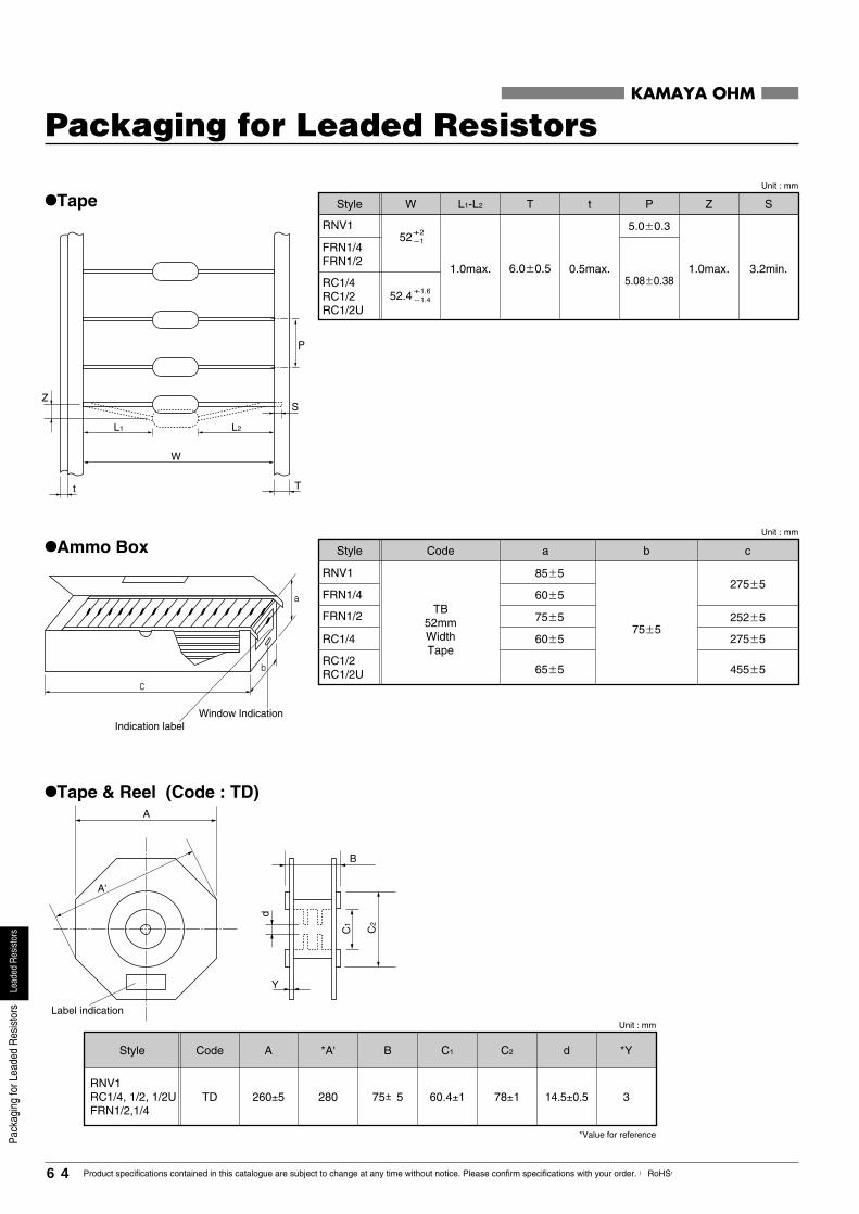
Z
t T
S
P
L2L1
W
C
b
a
•Tape
•Ammo Box85�5
60�5
75�5
60�5
65�5
75�5
TB52mmWidthTape
275�5
252�5
275�5
455�5
RNV1
FRN1/4
FRN1/2
RC1/4
RC1/2RC1/2U
A
Label indication
A'
C2
C1
d
B
Y
•Tape & Reel (Code : TD)
*Value for reference
RNV1RC1/4, 1/2, 1/2UFRN1/2,1/4
75±5 78±1 14.5±0.5260±5 60.4±1TD 280 3
KAMAYA OHM
Packaging for Leaded Resistors
Indication labelWindow Indication
a b cStyle Code
Unit : mm
Unit : mm
Style C1BACode *A' C2 d *Y
Unit : mm
Style PtW L1-L2 T Z S
1.0max. 3.2min.6.0�0.5 0.5max.1.0max.
FRN1/4FRN1/2
RNV1
5.08�0.38
5.0�0.3
RC1/4RC1/2RC1/2U
+2-152
+1.6-1.452.4
64 Product specifications contained in this catalogue are subject to change at any time without notice. Please confirm specifications with your order. 【RoHS】
Lead
edRe
sisto
rsPa
ckag
ing
forL
eade
dR
esis
tors

•Horizontal Forming (Code : H)
10.0±0.51.5max.
H60RC1/4
12.5±0.5H62RC1/4
15.0±0.5RC1/2RC1/2U 1.8max.H
RNV115.0±1.0
5.0±0.5
1.5max.H77
25.0±1.0H78A
t
B
•Horizontal Forming (Free-Standing) (Code : HB)
•Horizontal Forming (Kinked) (Code : HA)
A
Application : FRN, RNV
BC t P
A
Q
P
BC
FRN1/4FRN1/2
5.0±0.5 1.5max.12.5±1.0
15.0±1.0HA
FRN1
+1.5 08.0 +1
01.0
Note. Recommended PCB hole : FRN1/4,1/2 : φ0.75−φ0.85 FRN1, RNV1 : φ0.9−φ1.05
1.5max.10.0±1.0
12.5±1.0
15.0±1.0
HB
FRN 1/4
FRN 1/21.2±0.2
5.0±1.5
5.0±1.5
RNV1FRN1 1.4±0.2 1.5max.
+1.5 08.0
+1.5 08.0
Style Code A B t
Unit : mm
KAMAYA OHM
PACKAGING FOR LEADED RESISTORS
Style B C t PACode
Unit : mm
Style QCACode B P
Unit : mm
RC1/2 3,000 260 24,000 13 0.04 52 2,000 30,000 16 0.05 5,000 30,000 13
13
0.04
RC1/2U 3,000 260 24,000 13 0.04 52 2,000 30,000 16 0.05 5,000 30,000 13 0.04
RC1/4 5,000 260 40,000 12 0.04 52 2,000 30,000 10
10
0.03 10,000 50,000 0.04
FRN1 - - - -
10
12
- - - - - - 3,000 12,000 10 0.03
FRN1/2 3,000 260 24,000 0.04 52 2,000 24,000 0.02 7,000 28,000 10 0.03
FRN1/4 5,000 260 40,000 0.04 52 2,000 40,000 0.03 8,000 32,000 9 0.03
RNV1 1,500 260 12,000 12 0.04 52 1,000 12,000 11 0.02 4,000 12,000 10 0.03
13
JW -52 10,000 60,000 15 0.02
500
500
1000
250
500
500
250
1000 ※26 5,000 150,000 17 0.03
Style
Tape & ReelOuter Carton
Ammo BoxOuter Carton
Bulk PackagingOuter Carton Q'ty /
( ) Q'ty /Reel(pcs.)
Reel Size(mm)
Q'ty /Carton(pcs.)
Gross Weight(kg)
Measure-ment(m3)
Q'ty /Carton(pcs.)
Gross Weight(kg)
Measure-ment(m3)
Q'ty /Carton(pcs.)
Gross Weight(kg)
Measure-ment(m3)
Width ofTaping(mm)
Q'ty / Box(pcs.)
M.P.Q.Q'ty /
Plastic Bagpcs.
(100×5)
(100×5)
(200×5)
(50×5)
(100×5)
(100×5)
(50×5)
(200×5)
InnerCarton(pcs.)
※Please contact Kamaya Sales Dept.
65Product specifications contained in this catalogue are subject to change at any time without notice. Please confirm specifications with your order. 【RoHS】
Lead
edRe
sisto
rsPa
ckag
ing
forL
eade
dR
esis
tors

KAMAYA OHM
•Color coding
Product Marking
Black
Color
0
1st color band1st figure
0
2nd color band2nd figure
100
3rd color bandMultiplier
−
Brown 1 1 101 F(�1%)Red 2 102 G(�2%)
Orange 3 103 −
Yellow 4 104 −
Green 5 105 −
Blue 6 106 −
Purple 7 107 −
Gray 8 108 −
White 9 109 −
Gold − 10-1 J(�5%) Silver − 10-2 K(�10%)
Not colored −
23456789−
−
− − M(�20%)
4th color bandResistance tolerance
Black
Color
0
1st color band
0
3rd color band
100
4th color band
−
Brown 1 1 101 F(�1%)Red 2 102 G(�2%)
Orange 3 103 −
Yellow 4 104 −
Green 5 105
Blue 6 106
Purple 7 107
Gray 8 108 −
White 9 109 −
−
−
Gold − 10-1
D(�0.5%)
Silver − 10-2
C(�0.25%)
23456789−
−
0
2nd color band
123456789−
−
B(�0.1%)
5th color band
7
1st color bandPurple
4th color bandGold10-16
2nd color bandBlue
5th color bandBrown
1
1st color bandBrown
120k ohm J
3rd color bandYellow
�5%1042
2nd color bandRed
4th color bandGold
• Three - color band or four - color band system • Five - color band system
• Example • Example
•Rated resistance symbolsThe symbols to indicate rated resistance are depicted in 3 characters (for the E6, E12 and E24 series) or 4 characters (for the E48, E96 and E192 series) as indicated below.In the case of 3 characters, the first and second character represent the effective numeral, and the third character is the multiplier following the effective numeral.In the case of 4 characters, the first, second and third character represent the effective numeral, and the fourth character is the multiplier following the effective numeral.When a decimal point exists, the decimal point is represented by an R for all effective numerals.
1st figure 2nd figure 3rd figure Multiplier Resistance tolerance
*RC1/2U : Please refer to page 56.
R15Rated resistance symbols
0.15 ohm1R5 1.5 ohm150 15 ohm151 150 ohm152 1.5k ohm153 15k ohm154 150k ohm155 1.5M ohm156 15M ohm157 150M ohm
Resistance value
• 3-Digit (example)
R154Rated resistance symbols
0.154 ohm1R54 1.54 ohm15R4 15.4 ohm1540 154 ohm1541 1.54k ohm1542 15.4k ohm1543 154k ohm1544 1.54M ohm1545 15.4M ohm1546 154M ohm
Resistance value
• 4-Digit (example) • Resistance values of 100M ohm and greater(example)
100G
Rated resistance symbols
100G ohm10G0 10G ohm1G00 1G ohm100M 100M ohm
Resistance value
*The letters M and G are used as multipliers for 106 and 109 respectively of the resistance value expressed in ohms.
�1%12 10,000 (ohm) �5%
8768 0.1 (ohm) �1%
76.8 ohm F
3rd color bandGray
*For three-color band system the 4th color band is eliminated (Resistance tolerance is �20%).
66
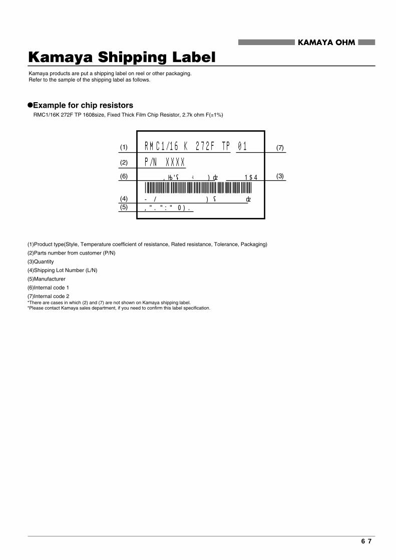
KAMAYA OHM
Kamaya Shipping Label Kamaya products are put a shipping label on reel or other packaging.Refer to the sample of the shipping label as follows.
•Example for chip resistors RMC1/16K 272F TP 1608size, Fixed Thick Film Chip Resistor, 2.7k ohm F(±1%)
(1)Product type(Style, Temperature coefficient of resistance, Rated resistance, Tolerance, Packaging)
(2)Parts number from customer (P/N)
(3)Quantity
(4)Shipping Lot Number (L/N)
(5)Manufacturer
(6)Internal code 1
(7)Internal code 2*There are cases in which (2) and (7) are not shown on Kamaya shipping label.*Please contact Kamaya sales department, if you need to confirm this label specification.
(1) (7)
(3)
(2)
(6)
(4)(5)
RMC1/16 K 272F TP 01P/N XXXX
L / N 071412282H ( 70815 ) KAMAYA OHM
2 . 7 KΩF(52-50H) 5000PCS
67
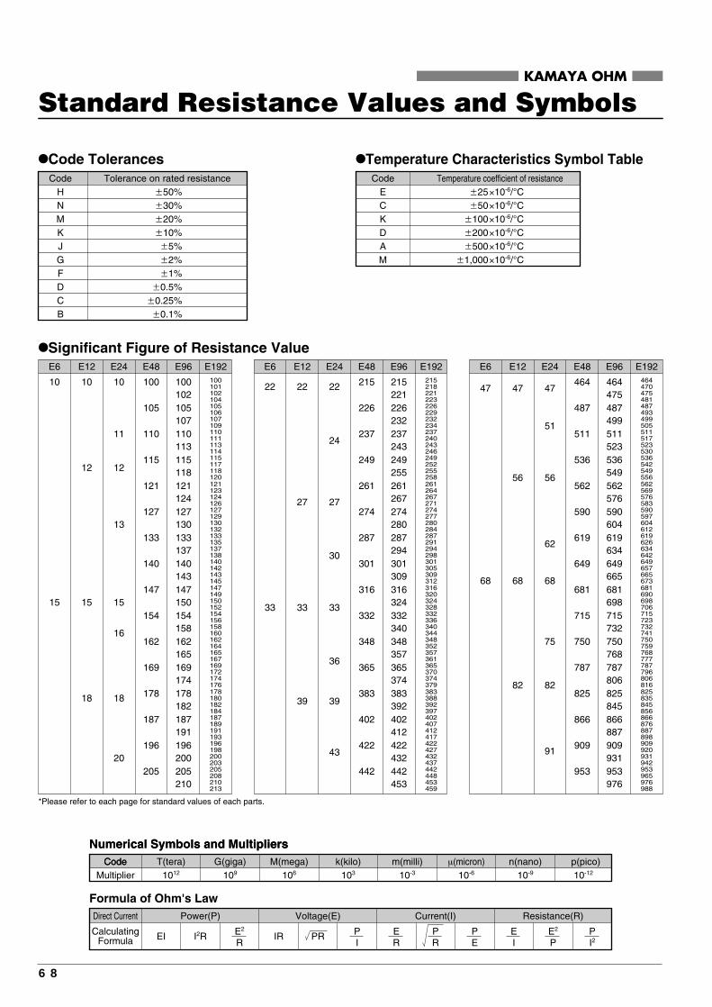
KAMAYA OHM
•Code Tolerances
Standard Resistance Values and Symbols
•Temperature Characteristics Symbol Table
E ×10-6/°CC ×10-6/°CK ×10-6/°CD ×10-6/°CA ×10-6/°CM ×10-6/°C
�25�50
�100�200�500
�1,000
H �50%N �30%M �20%K �10%J �5%G �2%F �1%D �0.5%C �0.25%B �0.1%
E192
100102105107110113115118121124127130133137140143147150154158162165169174178182187191196200205210
100101102104105106107109110111113114115117118120
178180182184187189191193196198200203205208210213
121123124126127129130132133135137138140142143145147149150152154156158160162164165167169172174176
E96
100
105
110
115
121
127
133
140
147
154
162
169
178
187
196
205
E48
10
11
12
13
15
16
18
20
E24
10
12
15
18
10
15
E12E6 E192
464475487499511523536549562576590604619634649665681698715732750768787806825845866887909931953976
464470475481487493499505511517523530536542549556
825835845856866876887898909920931942953965976988
562569576583590597604612619626634642649657665673681690698706715723732741750759768777787796806816
E96
464
487
511
536
562
590
619
649
681
715
750
787
825
866
909
953
E48
47
51
56
62
68
75
82
91
47
56
68
82
47
68
E24E12E6E192
215221226232237243249255261267274280287294301309316324332340348357365374383392402412422432442453
215218221223226229232234237240243246249252255258
383388392397402407412417422427432437442448453459
261264267271274277280284287291294298301305309312316320324328332336340344348352357361365370374379
E96
215
226
237
249
261
274
287
301
316
332
348
365
383
402
422
442
E48
22
24
27
30
33
36
39
43
22
27
33
39
22
33
E24E12E6•Significant Figure of Resistance Value
*Please refer to each page for standard values of each parts.
Direct Current
CalculatingFormula EI
Power(P)
Formula of Ohm's Law
I2R E2
RIR
Voltage(E)
PR PI
Current(I)
PE
ER
PR
Resistance(R)
PI2
E2
PEI
1012 109 106 103 10-3 10-6 10-9 10-12
CodeMultiplier
T(tera) G(giga) p(pico)
Numerical Symbols and MultipliersCode M(mega) k(kilo) m(milli) µ(micron) n(nano)
Numerical Symbols and Multipliers
CodeCode Temperature coefficient of resistanceTolerance on rated resistance
68
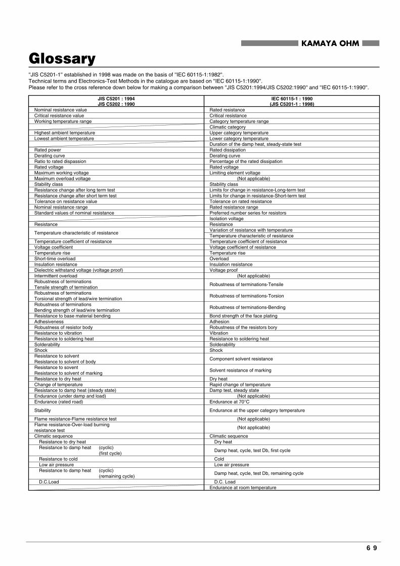
KAMAYA OHM
Glossary
Nominal resistance valueCritical resistance valueWorking temperature range
Highest ambient temperatureLowest ambient temperature
Rated powerDerating curveRatio to rated dispassionRated voltageMaximum working voltageMaximum overload voltageStability classResistance change after long term test Resistance change after short term testTolerance on resistance valueNominal resistance rangeStandard values of nominal resistance
Resistance
Temperature characteristic of resistance
Temperature coefficient of resistanceVoltage coefficientTemperature riseShort-time overloadInsulation resistanceDielectric withstand voltage (voltage proof)Intermittent overloadRobustness of terminationsTensile strength of termination Robustness of terminationsTorsional strength of lead/wire terminationRobustness of terminationsBending strength of lead/wire termination Resistance to base material bendingAdhesivenessRobustness of resistor bodyResistance to vibrationResistance to soldering heatSolderabilityShockResistance to solventResistance to solvent of bodyResistance to soventResistance to solvent of markingResistance to dry heatChange of temperatureResistance to damp heat (steady state)Endurance (under damp and load)Endurance (rated road)
Stability
Flame resistance-Flame resistance testFlame resistance-Over-load burningresistance testClimatic sequence
Resistance to dry heatResistance to damp heat (cyclic)
(first cycle)Resistance to coldLow air pressureResistance to damp heat (cyclic)
(remaining cycle)D.C.Load
JIS C5201 : 1994JIS C5202 : 1990
Rated resistanceCritical resistanceCategory temperature rangeClimatic categoryUpper category temperatureLower category temperatureDuration of the damp heat, steady-state testRated dissipationDerating curvePercentage of the rated dissipationRated voltageLimiting element voltage (Not applicable)Stability classLimits for change in resistance-Long-term testLimits for change in resistance-Short-term testTolerance on rated resistanceRated resistance rangePreferred number series for resistorsIsolation voltageResistanceVariation of resistance with temperatureTemperature characteristic of resistanceTemperature coefficient of resistanceVoltage coefficient of resistanceTemperature riseOverloadInsulation resistanceVoltage proof (Not applicable)
Robustness of terminations-Tensile
Robustness of terminations-Torsion
Robustness of terminations-Bending
Bond strength of the face platingAdhesionRobustness of the resistors boryVibrationResistance to soldering heatSolderabilityShock
Component solvent resistance
Solvent resistance of marking
Dry heatRapid change of temperatureDamp test, steady state (Not applicable)Endurance at 70°C
Endurance at the upper category temperature
(Not applicable)
(Not applicable)
Climatic sequenceDry heat
Damp heat, cycle, test Db, first cycle
ColdLow air pressure
Damp heat, cycle, test Db, remaining cycle
D.C. LoadEndurance at room temperature
IEC 60115-1 : 1990(JIS C5201-1 : 1998)
''JIS C5201-1'' established in 1998 was made on the basis of ''IEC 60115-1:1982''.Technical terms and Electronics-Test Methods in the catalogue are based on ''IEC 60115-1:1990''.Please refer to the cross reference down below for making a comparison between ''JIS C5201:1994/JIS C5202:1990'' and ''IEC 60115-1:1990''.
69

KAMAYA OHM
Term Explanation
R0
R-R0
T-T0
1
■ Resistors Rated Dissipation The maximum value of the electric power that can continuously be impressed to the resistor at the ambient temperature provided for within the category temperature range is indicated. The derated values of dissipation for temperatures in excess of 70℃ shall be indicated by the derating Curve.
Please note that the chip resistor networks provide for the rated dissipation of each element and each package when you use it. Rated Voltage The maximum value of the D.C or r.m.s. voltage that can continuously be impressed to the resistor at the ambient temperature provided for within the range of the category temperature range is indicated.
Rated Voltage = (Rated Dissipation) (Rated Resistance). (d.c. or a.c. r.m.s. Voltage)
However, Limiting Element Voltage can only be applied to resistors when the resistance value is equal to or higherthan the critical resistance value. Critical Resistance Value Critical resistance value is the resistance value at which the rated voltage is equal to the limiting element voltage.Below critical resistance value, please use the rated voltage as the limiting element voltage.
Limiting Element Voltage The maximum value of the d.c. or r.m.s. voltage that can continuously be impressed to the resistor and the resistive element is indicated.Limiting Element Voltage that provides for the kind and each shape is different. Isolation VoltageThe maximum value of the d.c. voltage that can be impressed for 1 minute the one that the electrode (terminal) was lumped together and between the insulation exterior or substrates is indicated.When the voltage that exceeds the isolation voltage is impressed for the electrode and the insulation exterior (substrate), the insulation exterior might be destroyed by generation of heat and the direct current electrolysis action by the leakage current. Voltage proof The r.m.s voltage is impressed for 1 minute the one that the electrode (terminal) was lumped together and between the insulation exterior or substrates, and the insulation exterior indicates the maximum value of the voltage that breakdown or flashover. Category Temperature Range The ambient temperature of the resistor that can continuously be used adding a regulated rated load (electric power) is shown.It is not a temperature of air outside of an electronic equipment, and it is necessary to compare it with the ambient temperaturein the electronic equipment in which the resistor is built in. Derating Curve The derated values of dissipation for temperatures in excess of 70℃ shall be indicated by the following Curve. Variation of resistance with temperature (Temperature Coefficient of Resistance: TCR)The change of resistance 1℃ rate of the resistor within the range of the category temperature (category temperature range) is shown. Temperature Coefficient of Resistance: TCR(×10-6/℃)= × ×10-6
R :Measured resistance at T℃R0 :Measured resistance at T℃T :Measured test temperature (℃)T 0 :Measured base temperature (℃)
Especially, because the resistance temperature coefficient tends the large dependence of the measurement resistanceon the measuring method, RLC/RLS/RCC/RLP&MLP needs noting.
70
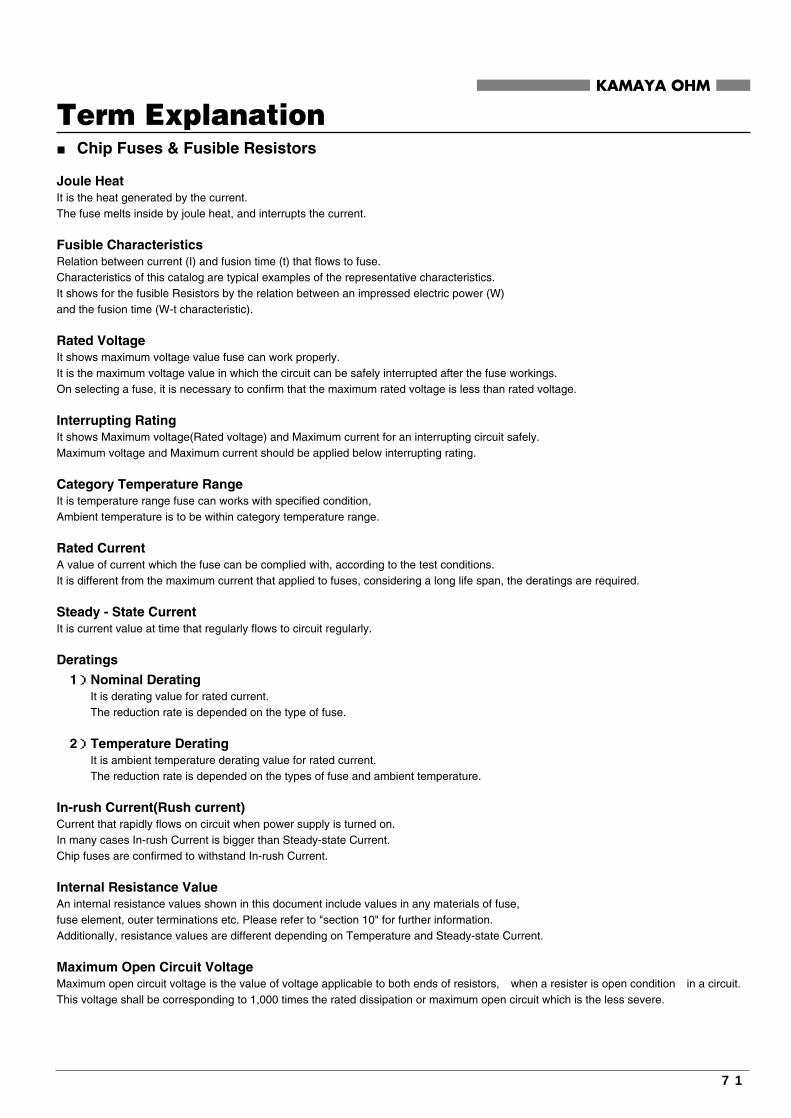
Term Explanation■ Chip Fuses & Fusible Resistors Joule Heat It is the heat generated by the current.The fuse melts inside by joule heat, and interrupts the current. Fusible Characteristics Relation between current (I) and fusion time (t) that flows to fuse.Characteristics of this catalog are typical examples of the representative characteristics.It shows for the fusible Resistors by the relation between an impressed electric power (W)and the fusion time (W-t characteristic). Rated Voltage It shows maximum voltage value fuse can work properly.It is the maximum voltage value in which the circuit can be safely interrupted after the fuse workings.On selecting a fuse, it is necessary to confirm that the maximum rated voltage is less than rated voltage. Interrupting Rating It shows Maximum voltage(Rated voltage) and Maximum current for an interrupting circuit safely.Maximum voltage and Maximum current should be applied below interrupting rating. Category Temperature Range It is temperature range fuse can works with specified condition,Ambient temperature is to be within category temperature range. Rated Current A value of current which the fuse can be complied with, according to the test conditions.It is different from the maximum current that applied to fuses, considering a long life span, the deratings are required. Steady - State Current It is current value at time that regularly flows to circuit regularly. Deratings
1)Nominal Derating It is derating value for rated current. The reduction rate is depended on the type of fuse. 2)Temperature Derating It is ambient temperature derating value for rated current. The reduction rate is depended on the types of fuse and ambient temperature. In-rush Current(Rush current) Current that rapidly flows on circuit when power supply is turned on.In many cases In-rush Current is bigger than Steady-state Current.Chip fuses are confirmed to withstand In-rush Current. Internal Resistance Value An internal resistance values shown in this document include values in any materials of fuse,fuse element, outer terminations etc. Please refer to "section 10" for further information.Additionally, resistance values are different depending on Temperature and Steady-state Current. Maximum Open Circuit Voltage Maximum open circuit voltage is the value of voltage applicable to both ends of resistors, when a resister is open condition in a circuit.This voltage shall be corresponding to 1,000 times the rated dissipation or maximum open circuit which is the less severe.
KAMAYA OHM
71

KAMAYA OHM
MEMO
72