Embed Size (px)
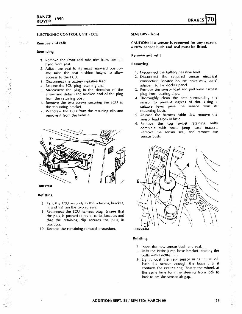
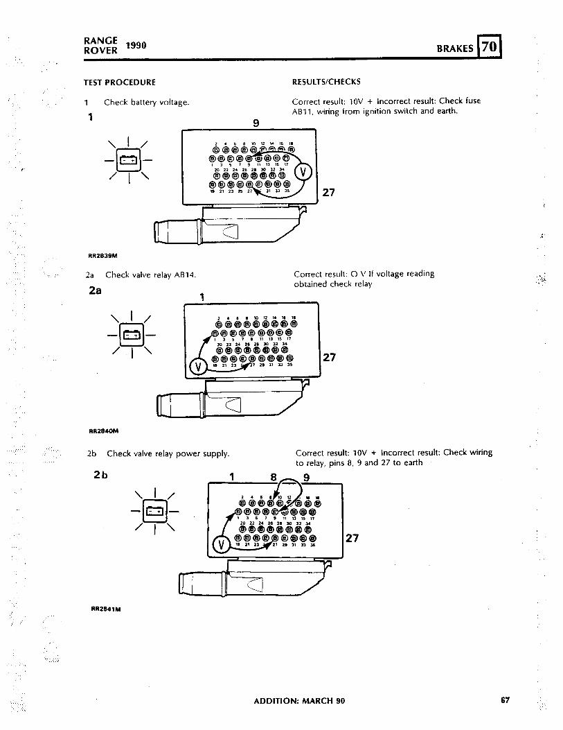
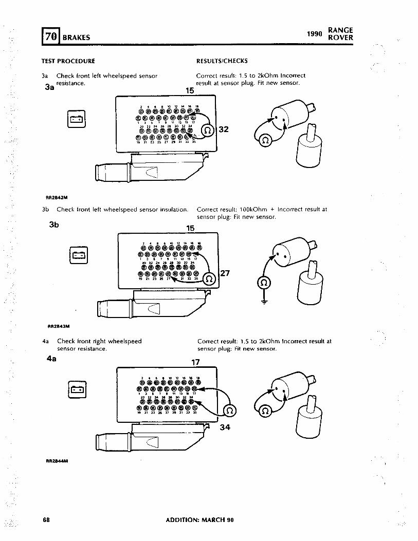
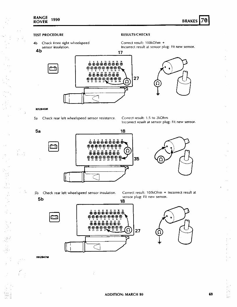
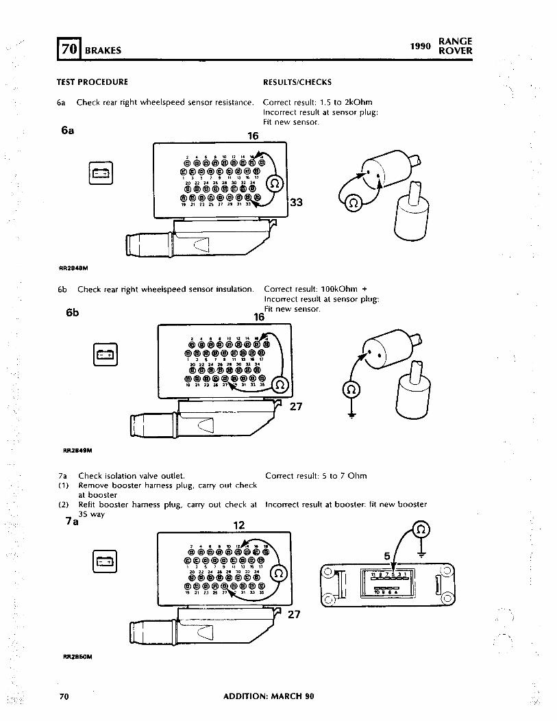
Citation preview
:
.
.t
:
.:
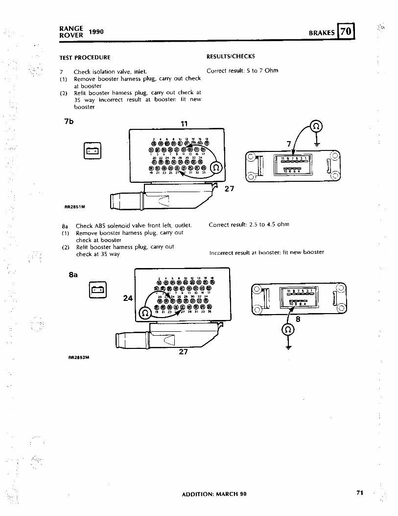
‘..:
‘.
.:. .:
:.’
.: :
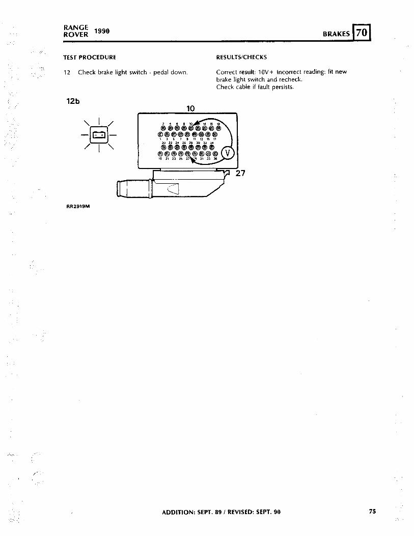
‘.’
_:. ., ‘:
KAlYU,tROVER lg8’
BRAKE SYSTEM - Description
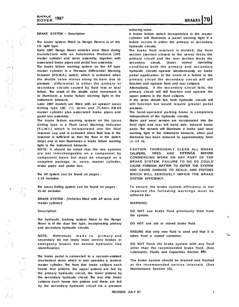
The brake system fitted to Range Rovers is of theI.H. split type.Early 1987 Range Rover vehicles were fitted duringmanufacture with an Automotive Products (AP)master cylinder and servo assembly, together withassociated brake pipes and pedal box assembly.The brake failure warning system on the AP typemaster cylinder is a Pressure Differential WarningActuator (P.D.W.A.) switch, which is activated whenthe shutt le valve moves along its bore due topressure di f fe rent ia l in e i ther the pr imary orsecondary circuits caused by fluid loss or sealfailure. The result of the shuttle valve movement isto illuminate a brake failure warning light in theinstrument binnacle.Later 1987 models are fitted with an uprated LucasGirting type LSC 115 servo and 25,4mm AS/ASmaster cylinder plus associated brake pipes andpedal box assembly.The brake failure warning system on the LucasGirling type is a Fluid Level Warning Indicator(F.L.W.I.) which is incorporated into the f luidreservoir cap and is activated when fluid loss in thereservoir is sufficient so that the float in the switchdrops and in turn illuminates a brake failure warninglight in the instrument binnacle.NOTE: It should be noted that the two systemsare not interchangeable on a component bycomponent basis but must be changed as acomplete package, ie, servo, master cylinder,brake pipes and pedal box.
The AP system can be found on pages :1-19 inclusive.
The Lucas Girling system can be found on pages :31-42 inclusive.
BRAKE SYSTEM - (Vehicles fitted with AP servo andmaster cylinder)
Description
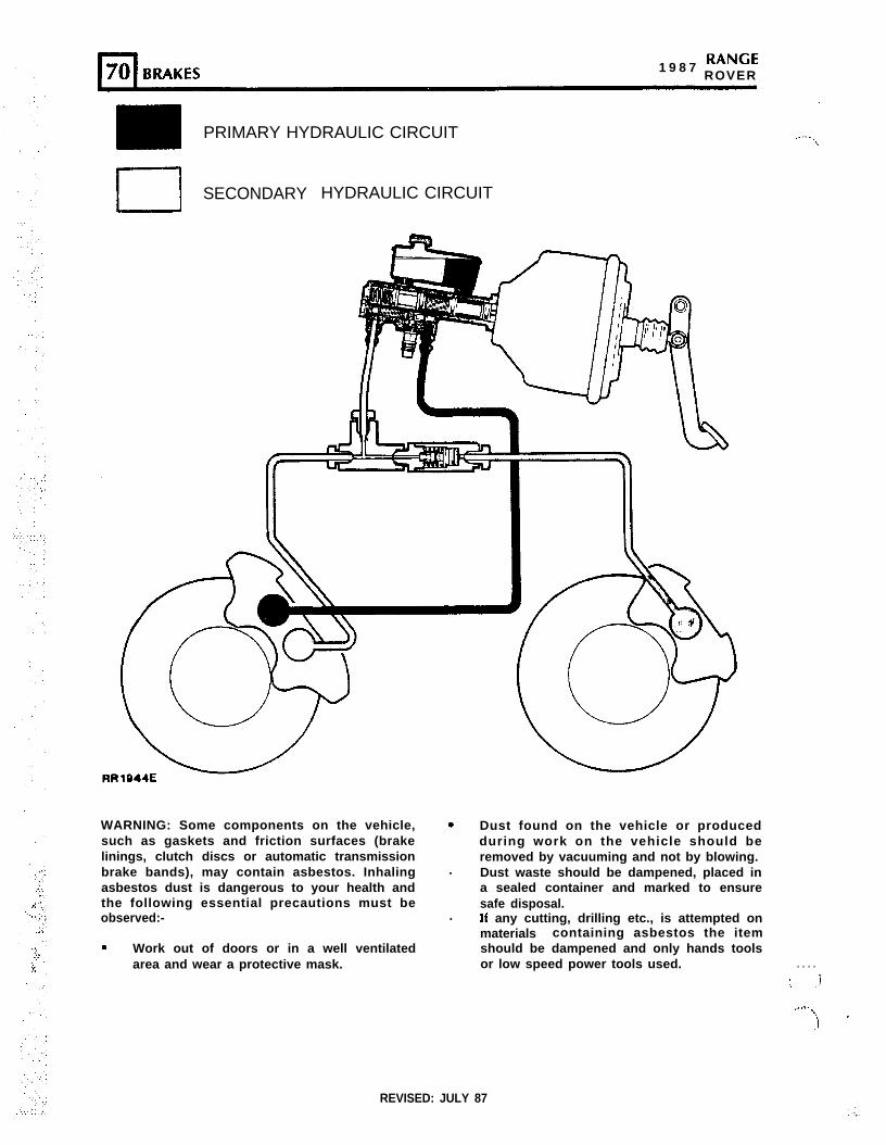
The hydraulic braking system fitted to the RangeRover is of the dual line type, incorporating primaryand secondary hydraulic circuits.
NOTE: References m a d e t o p r i m a r y a n dsecondary do not imply main service brakes oremergency brakes but denote hydraul ic l ineidentification.
The brake pedal is connected to a vacuum-assistedmechanical servo which in turn operates a tandemmaster cylinder. The front disc brake calipers eachhouse four pistons, the upper pistons are fed bythe primary hydraulic circuit, the lower pistons bythe secondary hydraulic circuit. The rear disc brakecalipers each house two pistons and these are fedby the secondary hydraulic circuit via a pressure
reducing valve.A brake failure switch incorporated in the mastercylinder will illuminate a panel warning light if afailure occurs in either the primary or secondaryhydraulic circuits.The brake f luid reservoir is divided, the frontsection (section closest to the servo) feeds theprimary circuit and the rear section feeds thesecondary circuit. Under normal operatingcondi t ions both the pr imary and secondaryhydraulic circuits operate simultaneously on brakepedal application. In the event 01 a failure in theprimary circuit the secondary circuit wil l st i l lfunction and operate front and rear calipers.Alternatively, i f the secondary circuit fai ls, theprimary circuit will still function and operate theupper pistons in the front calipers.If the servo should fail, both hydraulic circuits willst i l l function but would require greater pedalpressure.The hand-operated parking brake is completelyindependent of the hydraulic circuits.Brake pad wear sensors are incorporated into thefront right and rear left hand side, inboard brakepads. The sensors will illuminate a brake pad wearwarning light in the instrument binnacle, when padthickness has been reduced to approximately 3mm(0.118 in).
CAUTION: THOROUGHLY CLEAN ALL BRAKECALIPERS, PIPES AND FD-HNCS BEFORECOMMENCING WORK ON ANY PART OF THEBRAKE SYSTEM. FAILURE TO DO SO COULDCAUSE FOREIGN MATTER TO ENTER THE SYSTEMAND CAUSE DAMAGE TO SEALS, AND PISTONSWHICH WILL SERIOUSLY IMPAIR THE BRAKESYSTEM EFFICIENCY.
To ensure the brake system ef f ic iency is noti m p a i r e d t h e f o l l o w i n g w a r n i n g s m u s t b eadhered to:-
WARNING:
DO NOT use brake fluid previously bled fromthe system. 1
DO NOT use old or stored brake fluid.
ENSURE that only new fluid is used and that it istaken from a sealed container:
DO NOT flush the brake system with any fluidother than the recommended brake fluid. (SeeLubricants, Fluids and Capacities Section 09).
The brake system should be drained and flusheda t t h e r e c o m m e n d e d s e r v i c e i n t e r v a l s . ( S e eMaintenance Section 10).
REVISED: JULY 87 1
1 9 8 7 RANCEROVER
PRIMARY HYDRAULIC CIRCUIT ,...._\
El SECONDARY HYDRAULIC CIRCUIT
WARNING: Some components on the vehicle,such as gaskets and friction surfaces (brakelinings, clutch discs or automatic transmissionbrake bands), may contain asbestos. Inhalingasbestos dust is dangerous to your health andthe following essential precautions must beobserved:-
. Work out of doors or in a well ventilatedarea and wear a protective mask.
. Dust found on the vehicle or producedduring work on the vehicle should beremoved by vacuuming and not by blowing.
. Dust waste should be dampened, placed ina sealed container and marked to ensuresafe disposal.
. If any cutting, drilling etc., is attempted onmaterials containing asbestos the itemshould be dampened and only hands toolsor low speed power tools used. . . . .
; .i.,l.f
‘, ’
REVISED: JULY 87
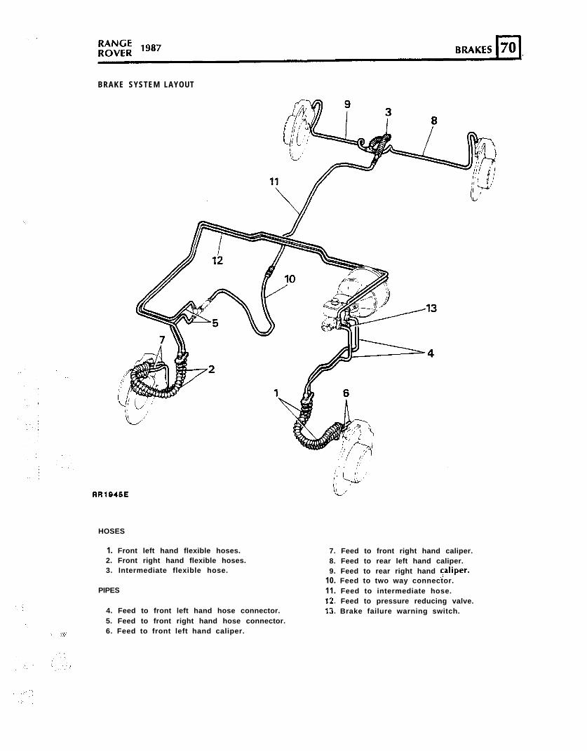
BRAKE SYSTEM LAYOUT
‘(.
RRlB45E
HOSES
1. Front left hand flexible hoses.2. Front right hand flexible hoses.3. Intermediate flexible hose.
PIPES
,..; 4. Feed to front left hand hose connector.5. Feed to front right hand hose connector.‘.
‘.’ :.:.::. 6. Feed to front left hand caliper.
7. Feed to front right hand caliper.8. Feed to rear left hand caliper.9. Feed to rear right hand 5aliper.
10. Feed to two way connector.11. Feed to intermediate hose.12. Feed to pressure reducing valve.13. Brake failure warning switch.
. ..I.:
.:.3 ’
‘.
._ .’
: .:.::::
‘.
‘.’
;’ ‘.
,’ ;’
.‘.
.:’ ,.,
‘.
‘.
;
RANGE“*’ ROVER
BRAKES
Bleed.
The hydraulic system comprises two completelyindependent sections. The rear calipers and thelower p i s tons in the f ront ca l ipers fo rm thesecondary section, while the upper pistons in thef ront ca l ipers fo rm the pr imary sect ion . Thefollowing procedure covers bleeding the completesystem, but it is permissible to bleed one sectiononly if disconnections are limited to that section.
Bleeding will be assisted if the engine is run or avacuum supply is connected to the servo.
WARNING: IF THE ENGINE IS RUNNING DURINGTHE BRAKE BLEEDING PROCESS ENSURE THATNEUTRAL GEAR IS SELECTED AND THAT THEPARKING BRAKE IS APPLIED.
When bleeding any part of the secondary section,almost full brake pedal travel is available. Whenbleeding the primary section only, brake pedaltravel will be restricted to approximately half.
WARNING: Before commencing to bleed thesystem it is necessary to loosen off the brakefailure warning switch to prevent the shuttlevalve damaging the switch unit.
1. Disconnect the leads from the switch.2. Unscrew the switch and insert the ‘C’ washer
between the switch and master cylinder beforedepressing the brake pedal.
3. After completion of bleeding, remove the ‘Clwasher and screw in the switch and tighten tothe correct torque (see section 06-Torquevalues).
4
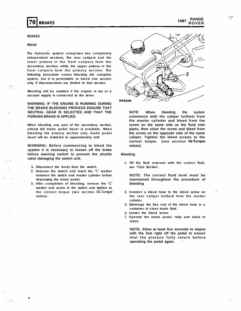
NOTE: When bleeding the systemcommence with the caliper furthest fromthe master cylinder and bleed from thescrew on the same side as the fluid inletpipes, then close the screw and bleed fromthe screw on the opposite side of the samecaliper. Tighten the bleed screws to thecorrect torque. (see section 06.Torquevalues).
Bleeding
1. Fill the fluid reservoir with the correct fluid,see IData Section’.
NOTE: The correct fluid level must bemaintained throughout the procedure ofbleeding
2. Connect a bleed hose to the bleed screw onthe rear caliper furthest from the mastercylinder.
.-
3. Submerge the free end of the bleed hose in acontainer of clean brake fluid.
4. Loosen the bleed screw.5. Operate the brake pedal -fully and allow to
return.
NOTE: Allow at least five seconds to elapsewith the foot right off the pedal to ensuretha t the p is tons fu l l y re tu rn be foreoperating the pedal again. ”
,,..;.
KWNbtROVER ls8’
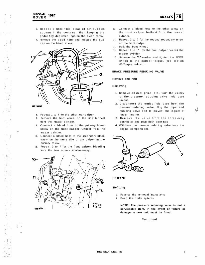
6. Repeat 5 unti l f luid clear of air bubblesappears in the container, then keeping thepedal fully depressed, tighten the bleed screw.
7. Remove the bleed hose and replace the dustcap on the bleed screw.
RR1646E
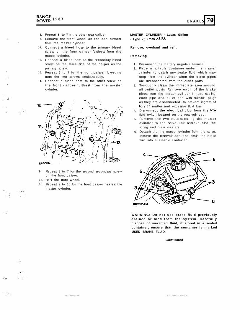
8.9.
10.
11.
12.
Repeat 1 to 7 for the other rear caliper.Remove the front wheel on the side furthestfrom the master cylinder.Connect a bleed hose to the primary bleedscrew on the front caliper furthest from themaster cylinder.Connect a bleed hose to the secondary bleedscrew on the same side of the caliper as theprimary screw.Repeat 3 to 7 for the front caliper, bleedingfrom the two screws simultaneously.
13.
14.
15.16.
17.
Connect a bleed hose to the other screw onthe front caliper furthest from the mastercylinder.Repeat 3 to 7 for the second secondary screwon the front caliper.Refit the front wheel.Repeat 9 to 15 for the front caliper nearest themaster cylinder.Remove the ‘C’ washer and tighten the PDWAswitch to the correct torque. (see section06-Torque values).
BRAKE PRESSURE REDUCING VALVE
Remove and refit
Removing
1. Remove all dust, grime, etc., from the vicinityof the pressure reducing valve f luid pipe
i
unions.2. Disconnect the outlet f luid pipe from the
pressure reducing valve. Plug the pipe andreducing valve port to prevent the ingress offoreign matter.
3 . R e m o v e t h e v a l v e f r o m t h e t h r e e - w a yconnector and plug both openings.
4. Withdraw the pressure reducing valve from theengine compartment.
RRlO4TE
Refitting
5. Reverse the removal instructions.6. Bleed the brake systems.
NOTE: The pressure reducing valve is not aserviceable item, in the event of failure ordamage, a new unit must be fitted.
Continued
REVISED: DEC. 87 5
..;.
i-l70 BRAKESRANGE
lg8’ ROVER
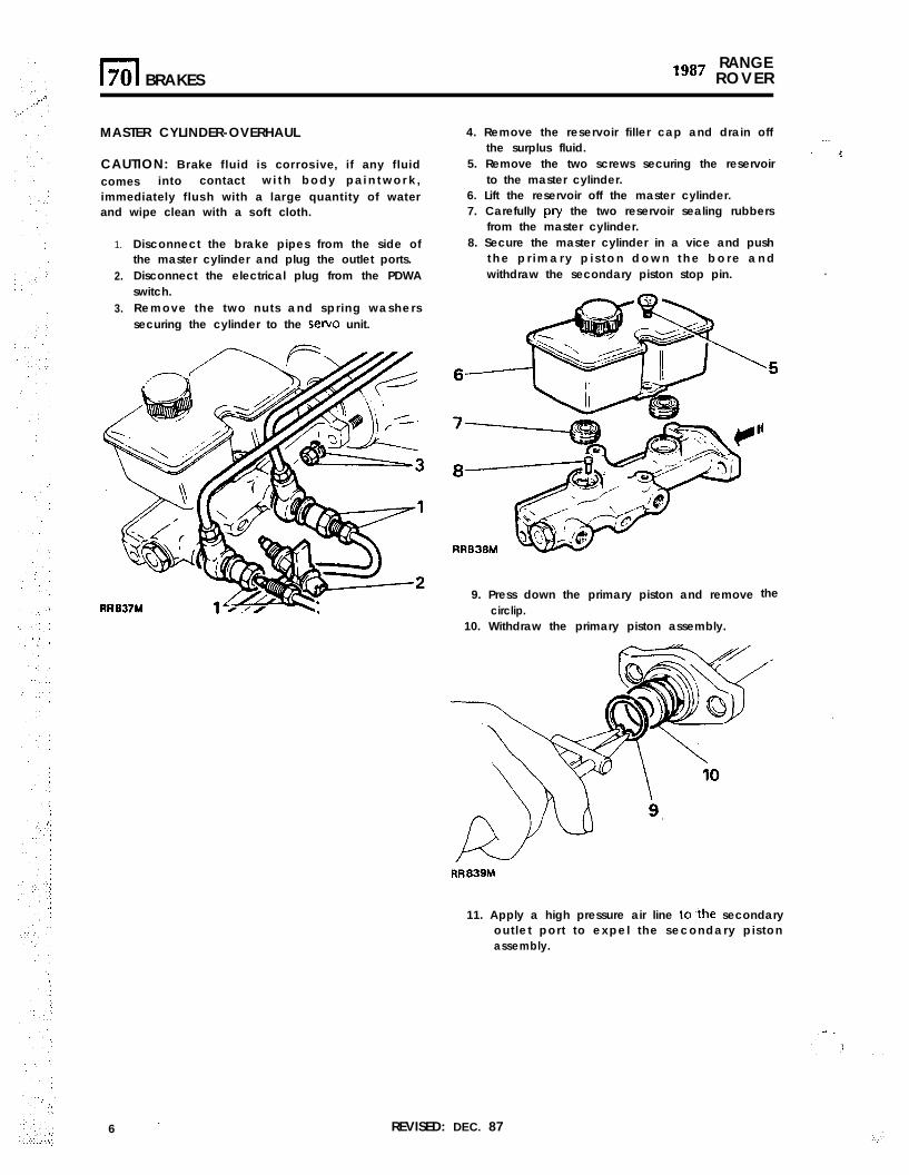
MASTER CYLINDER-OVERHAUL
CAUTION: Brake fluid is corrosive, if any fluidcomes into contact w i t h b o d y p a i n t w o r k ,immediately flush with a large quantity of waterand wipe clean with a soft cloth.
1.
2.
3.
Disconnect the brake pipes from the side ofthe master cylinder and plug the outlet ports.Disconnect the electrical plug from the PDWAswitch.Remove the two nuts and spring washerssecuring the cylinder to the servo unit.
6 ’ REVISED: DEC. 87
4. Remove the reservoir filler cap and drain offthe surplus fluid.
..-‘. !
5. Remove the two screws securing the reservoirto the master cylinder.
6. Lift the reservoir off the master cylinder.7. Carefully pry the two reservoir sealing rubbers
from the master cylinder.8. Secure the master cylinder in a vice and push
t h e p r i m a r y p i s t o n d o w n t h e b o r e a n dwithdraw the secondary piston stop pin. .
9. Press down the primary piston and removecirclip.
10. Withdraw the primary piston assembly.
the
RR839M
11. Apply a high pressure air line to?he secondaryoutlet port to expel the secondary pistonassembly.
,..:.’ 1
,(..’ .
:
; ‘.
,:
:.
.‘. .
‘.1
.’
”
,,‘..:(., :
: ‘:I,’ ‘,’‘. :
.I
.,:: :,.’
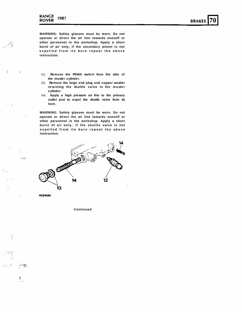
WARNING: Safety glasses must be worn. Do notoperate or direct the air line towards oneself orother personnel in the workshop. Apply a shortburst of air only, if the secondary piston is note x p e l l e d f r o m i t s b o r e r e p e a t t h e a b o v einstruction.
c12. Remove the PDWA switch from the side of
the master cylinder.13. Remove the large end plug and copper washer
retaining the shutt le valve in the mastercylinder.
14. Apply a high pressure air line to the primaryoutlet port to expel the shuttle valve from itsbore.
WARNING: Safety glasses must be worn. Do notoperate or direct the air line towards oneself orother personnel in the workshop. Apply a shortburst of a i r only , i f the shutt le va lve is note x p e l l e d f r o m i t s b o r e r e p e a t t h e a b o v einstruction.
RR84oM
Continued
i . .
” ,
: :’
.\’
,’
RANGE‘g87 ROVER
2
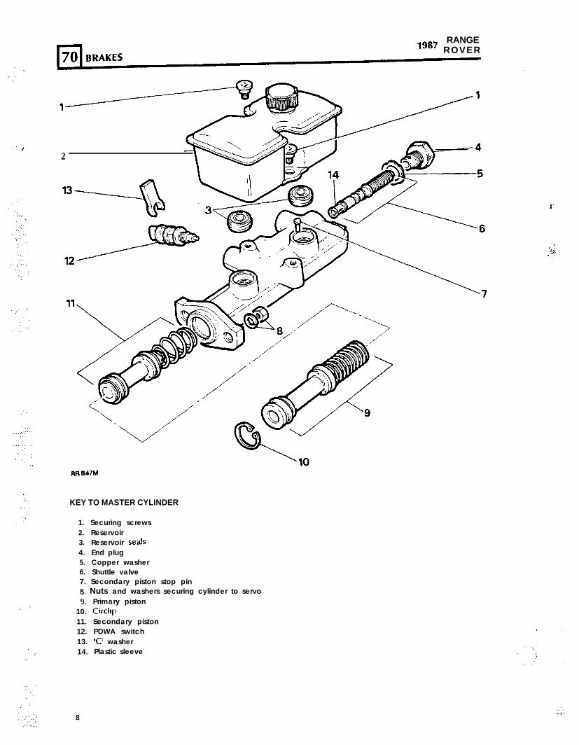
KEY TO MASTER CYLINDER
1. Securing screws2. Reservoir3. Reservoir seals4. End plug5. Copper washer6. Shuttle valve7. Secondary piston stop pin8. Nuts and washers securing cylinder to servo9. Primary piston
10. Circllp11. Secondary piston12. PDWA switch13. XI’ washer14. Plastic sleeve
8
RR 847M
PRIMARY PISTON SEALS SECONDARY PISTON SEALS
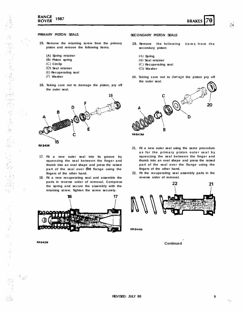
15. Remove the retaining screw from the primarypiston and remove the following items.
(A) Spring retainer(6) Piston spring(C) Circlip(D) Seal retainer(E) Recuperating seal(F) Washer
16. Taking care not to damage the piston, pry offthe outer seal.
16
/
17.
18.
. ..-.
Fit a new outer seal into its groove bysqueezing the seal between the finger andthumb into an oval shape and press the raisedpart of the seal over the flange using thefingers of the other hand.Fit a new recuperating seal and assemble theparts in reverse order of removal. Compressthe spring and secure the assembly with theretaining screw. Tighten the screw securely.
19. Remove the fo l lowing i t e m s f r o m t h esecondary piston:
(A) Spring(8) Seal retainer(C) Recuperating seal(D) Washer
20. Taking care not to damaRe the piston pry offthe outer seal.
21.
22.
Fit a new outer seal using the same procedureas fo r the pr imary p i s ton outer sea l bysqueezing the seal between the finger andthumb into an oval shape and press the raisedpart of the seal over the flange using thefingers of the other hand.Fit the recuperating seal assembly parts in thereverse order of removal.
RR842M
REVISED: JULY 88
RR844M
.I
Continued
9-j,..
RANGElg8’ ROVER
SHUTTLE VALVE ‘0’ RINGS
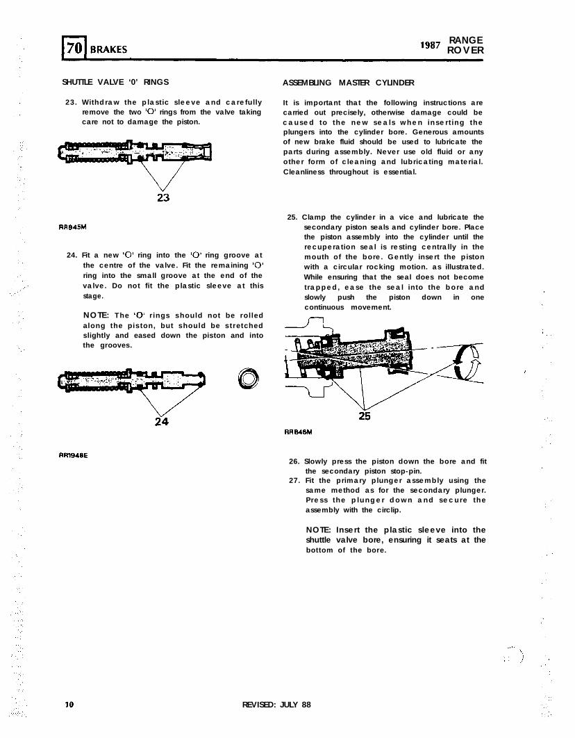
23. Withdraw the plastic sleeve and careful lyremove the two ‘0’ rings from the valve takingcare not to damage the piston.
23
RR845M
24. Fit a new ‘0’ ring into the ‘0’ ring groove atthe centre of the valve. Fit the remaining ‘0’ring into the small groove at the end of thevalve. Do not fit the plastic sleeve at thisstage.
NOTE: The ‘0’ rings should not be rolledalong the piston, but should be stretchedslightly and eased down the piston and intothe grooves.
24
fWl948E
ASSEMBLING MASTER CYLINDER
It is important that the following instructions arecarried out precisely, otherwise damage could becaused to the new seals when inser t ing theplungers into the cylinder bore. Generous amountsof new brake fluid should be used to lubricate theparts during assembly. Never use old fluid or anyother form of cleaning and lubricating material.Cleanliness throughout is essential.
25. Clamp the cylinder in a vice and lubricate thesecondary piston seals and cylinder bore. Placethe piston assembly into the cylinder until therecuperation seal is resting centrally in themouth of the bore. Gently insert the pistonwith a circular rocking motion. as illustrated.While ensuring that the seal does not becometrapped, ease the seal into the bore andslowly push the piston down in onecontinuous movement.
26. Slowly press the piston down the bore and fitthe secondary piston stop-pin.
27. Fit the primary plunger assembly using thesame method as for the secondary plunger.P ress the p lunger down and secure theassembly with the circlip.
NOTE: Insert the plastic sleeve into theshuttle valve bore, ensuring it seats at thebottom of the bore.
.‘.. 1.:
i. j‘, :
REVISED: JULY 88
”‘.
.
:‘. ,.
:.
:.
,...
‘. ., .’::
‘.‘.’
,,:. ,’
‘.
.:,’.:‘.3
.i :,‘. ). ., ;
::
::.x
:
1
I’* ,:‘,‘:“.‘..,, :.
28. Lubricate the ‘0’ rings and fit the shuttle valve.Fit the end plug using a new copper sealingwasher and tighten the plug securely.
CAUTION: To prevent damage to the ‘0’ ring atthe end of the valve ensure it remains in thesmall groove until the valve reaches the smallplastic sleeve.
29.
30.31.
32.
‘.‘.‘.,.“:’ 33.
Fit the plastic ‘C’ washer to the end of thePDWA switch and screw the switch into themaster cylinder.Fit new seals to the bottom of the reservoir.Press the reservoir into the lop of the mastercylinder and secure in position with the tworetaining screws.Fit the master cylinder to the servo and securewith the two nuts and spring washers andtighten to the correct torque (see section06-Torque values).Bleed the brakes, After final bleed remove the‘C’ washer from the PDWA switch and tightenthe switch to the correct torque (see section06-Torque values).
...PEDAL ASSEMBLY-OVERHAUL
Remove the pedal assembly
12
:
:,3.
4.
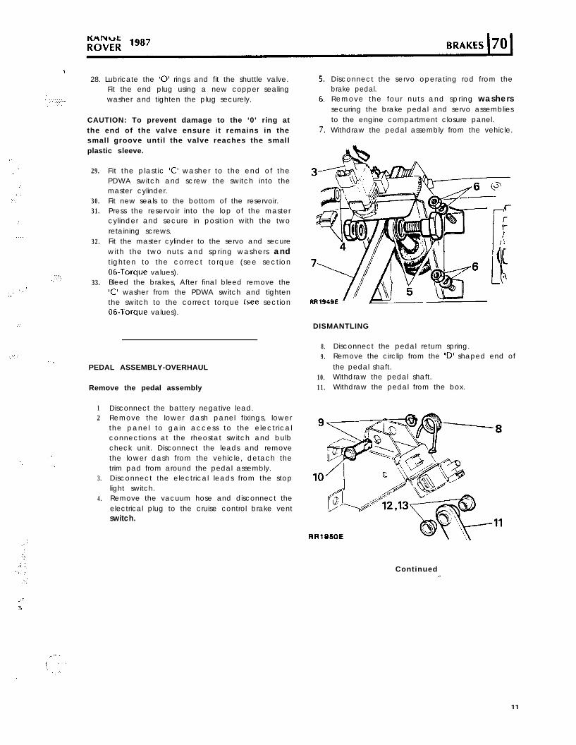
Disconnect the battery negative lead.Remove the lower dash panel fixings, lowerthe panel to gain access to the electricalconnections at the rheostat switch and bulbcheck unit. Disconnect the leads and removethe lower dash from the vehicle, detach thetrim pad from around the pedal assembly.Disconnect the electrical leads from the stoplight switch.Remove the vacuum hose and disconnect theelectrical plug to the cruise control brake ventswitch.
Disconnect the servo operating rod from thebrake pedal.Remove the four nuts and spring washerssecuring the brake pedal and servo assembliesto the engine compartment closure panel.Withdraw the pedal assembly from the vehicle.
DISMANTLING
8.9.
Disconnect the pedal return spring.Remove the circlip from the ID’ shaped end ofthe pedal shaft.
10. Withdraw the pedal shaft.11. Withdraw the pedal from the box.
RRlBSOE
Continued.a
,e- .
11
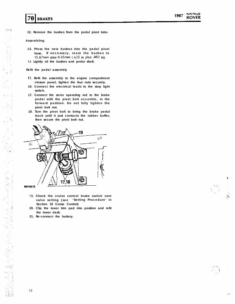
12. Remove the bushes from the pedal pivot tube.
Assembling
13. Press the new bushes into the pedal pivothose. ff necessary , ream the bushes to15.87mm plus 0.05mm (.625 in plus .002 in).
14. Lightly oil the bushes and pedal shaft.
Refit the pedal assembly
15. Refit the assembly to the engine compartmentclosure panel, tighten the four nuts securely.
16. Connect the electrical leads to the stop lightswitch.
17. Connect the servo operating rod to the brakepedal with the pivot bolt eccentric, in theforward posit ion. Do not ful ly t ighten thepivot bolt nut.
18. Turn the pivot bolt to bring the brake pedalback until it just contacts the rubber buffer,then secure the pivot bolt nut.
19. Check the cruise control brake switch ventvalve sett ing (see ‘Sett ing Procedure’ inSection 19 Cruise Control)
20. Clip the lower trim pad into position and refitthe lower dash.
21. Re-connect the battery.
12
‘.
,:’
,’ ;’
,
‘,
‘.‘, :
. . ,
0
..,’::
.,.I. 4 5I I 6
I“,,
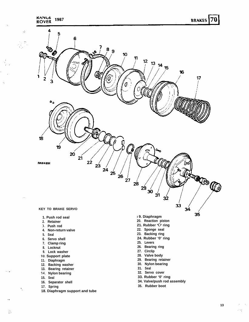
KEY TO BRAKE SERVO
RR848hl
1. Push rod seal2. Retainer3. Push rod4. Non-return valve5. Seal6. Servo shell7. Clamp ring8. Locknut9. Lock washer
IO. Support plate11. Diaphragm12. Backing washer13. Bearing retainer14. Nylon bearing15. Seal16. Separator shell17. Spring18. Diaphragm support and tube
I 9. Diaphragm20. Reaction piston21. Rubber ‘0’ ring22. Sponge seal23. Backing ring24. Rubber ‘0’ ring25. Levers26. Bearing ring27. Circlip28. Valve body29. Bearing retainer30. Nylon bearing31. Seal32. Servo cover33. Rubber ‘0’ ring34. Valve/push rod assembly35. Rubber boot
13 ”
RANGE70 BRAKES “*’ R O V E R
I
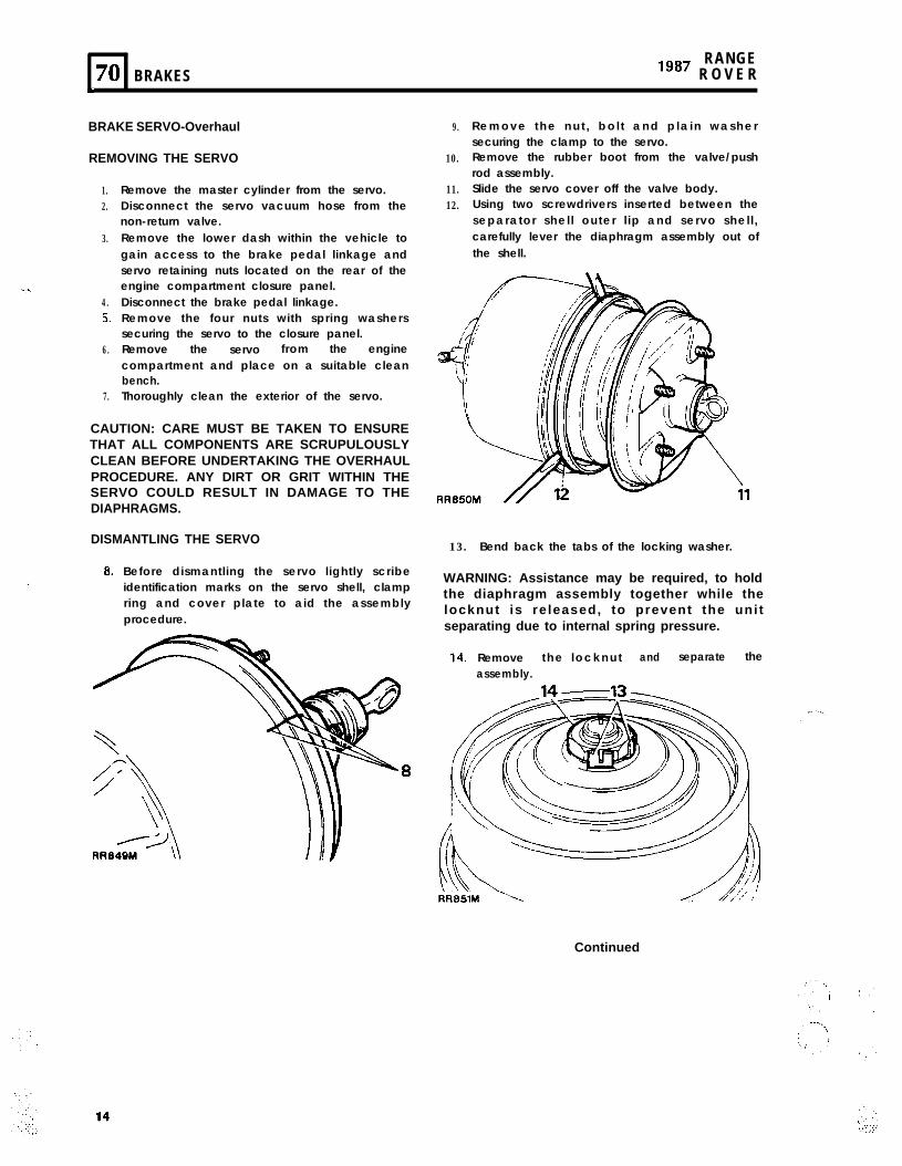
BRAKE SERVO-Overhaul
REMOVING THE SERVO
1.2.
3.
..:..4.53.
6.
7.
Remove the master cylinder from the servo.Disconnect the servo vacuum hose from thenon-return valve.Remove the lower dash within the vehicle togain access to the brake pedal linkage andservo retaining nuts located on the rear of theengine compartment closure panel.Disconnect the brake pedal linkage.Remove the four nuts with spring washerssecuring the servo to the closure panel.Remove the servo from the enginecompartment and place on a suitable cleanbench.Thoroughly clean the exterior of the servo.
CAUTION: CARE MUST BE TAKEN TO ENSURETHAT ALL COMPONENTS ARE SCRUPULOUSLYCLEAN BEFORE UNDERTAKING THE OVERHAULPROCEDURE. ANY DIRT OR GRIT WITHIN THESERVO COULD RESULT IN DAMAGE TO THEDIAPHRAGMS.
DISMANTLING THE SERVO
8.
‘.’
Before dismantling the servo lightly scribeidentification marks on the servo shell, clampring and cover plate to aid the assemblyprocedure.
9.
10.
11.12.
Remove the nut , bo l t and p la in washersecuring the clamp to the servo.Remove the rubber boot from the valve/pushrod assembly.Slide the servo cover off the valve body.Using two screwdrivers inserted between theseparator shell outer l ip and servo shell ,carefully lever the diaphragm assembly out ofthe shell.
13. Bend back the tabs of the locking washer.
WARNING: Assistance may be required, to holdthe diaphragm assembly together while thelocknut is re leased, to prevent the unitseparating due to internal spring pressure.
14. Remove the locknut and separate theassembly.
Continued
‘.‘..’,.‘:.I
; .(
; :
.)
_,
.:;,2’:
‘... ,.’..:’
x
. . .
. . .
BRAKES 70l-l
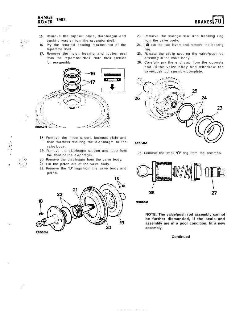
15..:: . .‘*‘i.;:: “:..:+.‘.
‘.. 16.:
17.
Remove the support plate, diaphragm andbacking washer from the separator shell.Pry the serrated bearing retainer out of theseparator shell.Remove the nylon bearing and rubber sealfrom the separator shell. Note their positionfor reassembly.
, .:::,,. 1:’.: ” :.
.:,zv.:
18. Remove the three screws, locknuts plain andfibre washers securing the diaphragm to thevalve body.
19. Remove the diaphragm support and tube fromthe front of the diaphragm.
20. Remove the diaphragm from the valve body.21. Pull the piston out of the valve body.22. Remove the ‘0’ rings from the valve body and
piston.
18
23.
24.
25.
26.
Remove the sponge seal and backing ringfrom the valve body.Lift out the two levers and remove the bearingring.Release the circlip securing the valve/push rodassembly in the valve body.Carefully pry the end cap from the oppositeend 01 the valve body and withdraw thevalve/push rod assembly complete.
27. Remove the small ‘0’ ring from the assembly.
RR855M
NOTE: The valve/push rod assembly cannotbe further dismantled, if the seals andassembly are in a poor condition, fit a newassembly.
_./
REVISED: APR. 87 15
Continued
; i
:
” ,
.,.,, > ;:..A, ;.;; ,.,‘:
RANGElg8’ ROVER
*
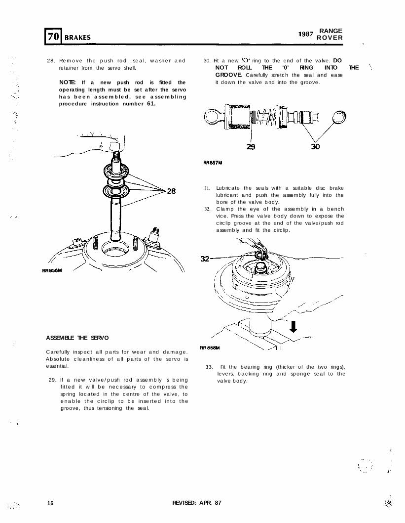
28. Remove the push rod, seal, washer andretainer from the servo shell.
NOTE: If a new push rod is fitted theoperating length must be set after the servoh a s b e e n a s s e m b l e d , s e e a s s e m b l i n gprocedure instruction number 61.
ASSEMBLE THE SERVO
Carefully inspect all parts for wear and damage.Absolute cleanliness of all parts of the servo isessential.
29. If a new valve/push rod assembly is beingfitted it will be necessary to compress thespring located in the centre of the valve, toenable the circl ip to be inserted into thegroove, thus tensioning the seal.
30. Fit a new ‘0’ ring to the end of the valve. DONOT ROLL THE ‘0’ RING INTO THE ‘IGROOVE. Carefully stretch the seal and easeit down the valve and into the groove.
RR857M
31.
32.
Lubricate the seals with a suitable disc brakelubricant and push the assembly fully into thebore of the valve body.Clamp the eye of the assembly in a benchvice. Press the valve body down to expose thecirclip groove at the end of the valve/push rodassembly and fit the circlip.
32
33. Fit the bearing ring (thicker of the two rings),levers, backing ring and sponge seal to thevalve body.
16 REVISED: APR. 87
. ...>.
,.
,_ i ,i
: ‘,’ ‘.. . ..:.
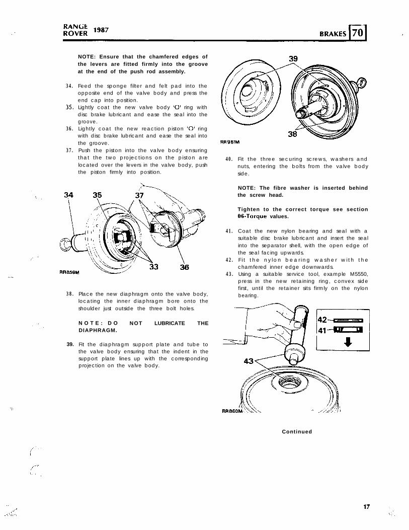
34.
35.
36.
37.
NOTE: Ensure that the chamfered edges ofthe levers are fitted firmly into the grooveat the end of the push rod assembly.
Feed the sponge filter and felt pad into theopposite end of the valve body and press theend cap into position.Lightly coat the new valve body ‘0’ ring withdisc brake lubricant and ease the seal into thegroove.Lightly coat the new reaction piston ‘0’ ringwith disc brake lubricant and ease the seal intothe groove.Push the piston into the valve body ensuringthat the two projections on the piston arelocated over the levers in the valve body, pushthe piston firmly into position.
38.
39.
Place the new diaphragm onto the valve body,locating the inner diaphragm bore onto theshoulder just outside the three bolt holes.
N O T E : D O NOT LUBRICATE THEDIAPHRAGM.
Fit the diaphragm support plate and tube tothe valve body ensuring that the indent in thesupport plate lines up with the correspondingprojection on the valve body.
40.
41.
42.
43.
Fit the three securing screws, washers andnuts, entering the bolts from the valve bodyside.
NOTE: The fibre washer is inserted behindthe screw head.
Tighten to the correct torque see sectionOC-Torque values.
Coat the new nylon bearing and seal with asuitable disc brake lubricant and insert the sealinto the separator shell, with the open edge ofthe seal facing upwards.F i t t h e n y l o n b e a r i n g w a s h e r w i t h t h echamfered inner edge downwards.Using a suitable service tool, example M5550,press in the new retaining ring, convex sidefirst, until the retainer sits firmly on the nylonbearing.
Continued
l-l70 BRAKESRANGE
lg8’ ROVER
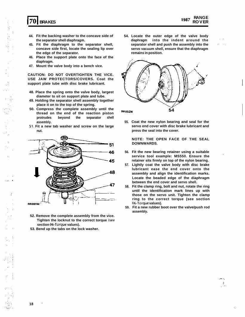
44.
45.
46.
Fit the backing washer to the concave side ofthe separator shell diaphragm.Fit the diaphragm to the separator shell,concave side first, locate the sealing lip overthe edge of the separator.Place the support plate onto the face of thediaphragm.
47. Mount the valve body into a bench vice.
CAUTION: DO NOT OVERTIGHTEN THE VICE.USE JAW PROTECTORS/COVERS. Coat thesupport plate tube with disc brake lubricant.
48. Place the spring onto the valve body, largestdiameter to sit on support plate and tube.
49. Holding the separator shell assembly togetherplace it on to the top of the spring.
50. Compress the complete assembly until thethread on the end of the reaction pistonprotrudes beyond the separator shellassembly.
51. Fit a new tab washer and screw on the largenut.
54. Locate the outer edge of the valve bodydiaphragm into the indent around theseparator shell and push the assembly into theservo vacuum shell, ensure that the diaphragmremains in position.
I
f’
55.
56.
57.
58.
59.
Coat the new nylon bearing and seal for theservo end cover with disc brake lubricant andpress the seal into the cover.
NOTE: THE OPEN FACE OF THE SEALDOWNWARDS.
Fit the new bearing retainer using a suitableservice tool example: MS550. Ensure theretainer sits firmly on top of the nylon bearing.Lightly coat the valve body with disc brakelubricant ease the end cover onto theassembly and align the identification marks.Locate the beaded edge of the diaphragmbetween the end cover and servo shell.Fit the clamp ring, bolt and nut, rotate the ringuntil the identification mark lines up withthose on the servo unit. Tighten the clampring to the correct torque (see section06-Torque values).Fit a new rubber boot over the valve/push rodassembly.
52. Remove the complete assembly from the vice.Tighten the locknut to the correct torque (seesection 06.Torque values).
53. Bend up the tabs on the lock washer.
..I .,
!., ,’
18 ’.:
I .-..
.
:
B R A K E S 70l-l
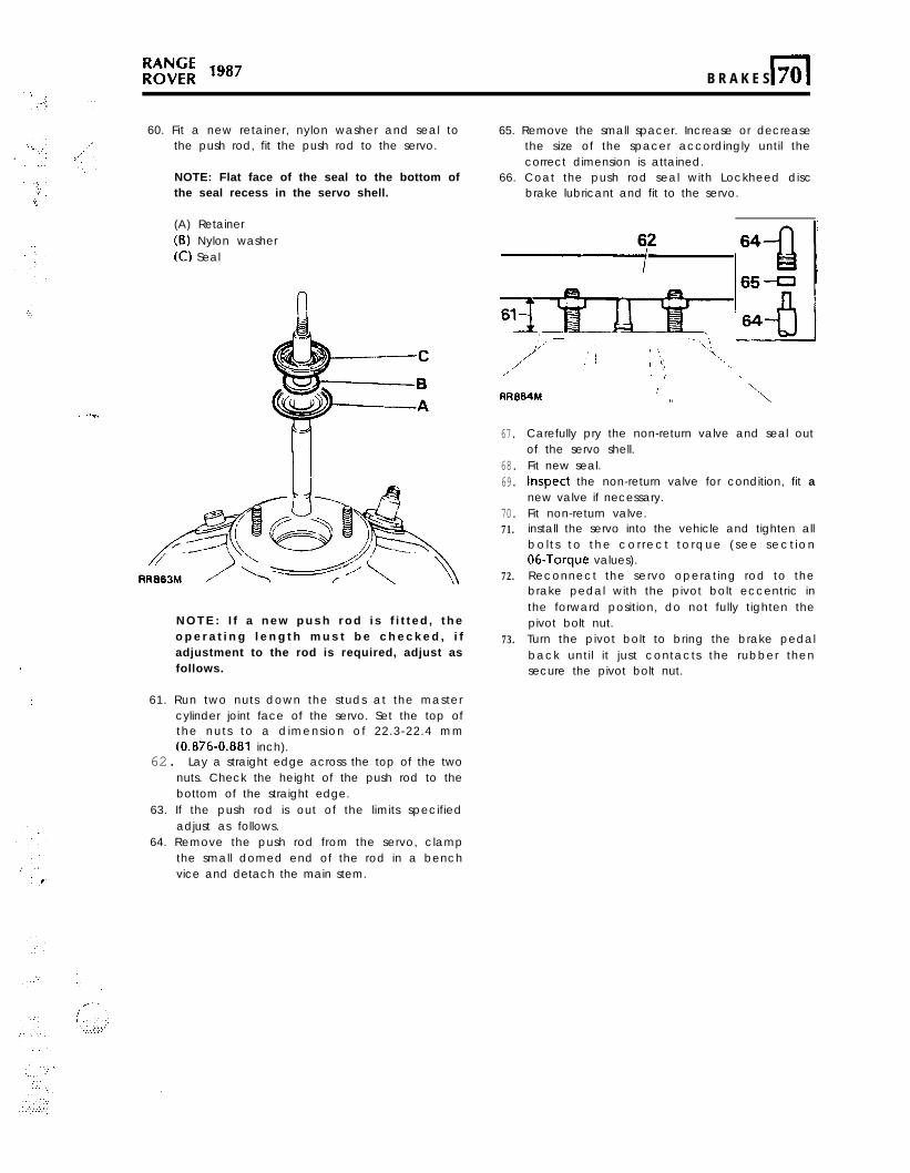
60. Fit a new retainer, nylon washer and seal tothe push rod, fit the push rod to the servo.
NOTE: Flat face of the seal to the bottom ofthe seal recess in the servo shell.
(A) Retainer(B) Nylon washer(C) Seal
N O T E : I f a n e w p u s h r o d i s f i t t e d , t h eo p e r a t i n g l e n g t h m u s t b e c h e c k e d , i fadjustment to the rod is required, adjust asfollows.
61. Run two nuts down the studs at the mastercylinder joint face of the servo. Set the top ofthe nuts to a dimension of 22.3-22.4 mm(0.876-0.881 inch).
62. Lay a straight edge across the top of the twonuts. Check the height of the push rod to thebottom of the straight edge.
63. If the push rod is out of the limits specifiedadjust as follows.
64. Remove the push rod from the servo, clampthe small domed end of the rod in a benchvice and detach the main stem.
65. Remove the small spacer. Increase or decreasethe size of the spacer accordingly until thecorrect dimension is attained.
66. Coat the push rod seal with Lockheed discbrake lubricant and fit to the servo.
,’ 3 i, .\
AR064M (’l.
1, ‘\
67.
68.69.
70.71.
72.
73.
Carefully pry the non-return valve and seal outof the servo shell.Fit new seal.Inspect the non-return valve for condition, fit anew valve if necessary.Fit non-return valve.install the servo into the vehicle and tighten allbol t s to the cor rect torque (see sect ion06-Torque values).Reconnect the servo operating rod to thebrake pedal with the pivot bolt eccentric inthe forward position, do not fully tighten thepivot bolt nut.Turn the pivot bolt to bring the brake pedalback until it just contacts the rubber thensecure the pivot bolt nut.
REVISED: JUNE 87 19
-.
%‘,,,. :,’ .‘.
‘.‘.’ .’
,. : .’
. .,:.‘)1.57. .,
‘.I.. ,.’,:,
:L‘.’x
._,.
;
: ; ,j,
RANGElg8’ R O V E R
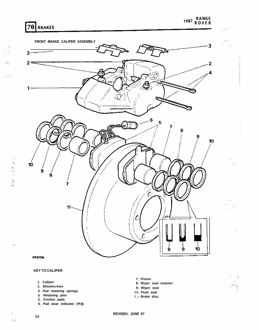
FRONT BRAKE CALIPER ASSEMBLY
RR870M
KEY TO CALIPER
1. Caliper2. Bleedscrews3. Pad retaining springs4. Retaining pins5. Friction pads6. Pad wear indicator plug
20
7. Piston8. Wiper seal retainer9. Wiper seal
IO. Fluid sealI I. Brake disc
REVISED: JUNE 67
BRAKES 70r l
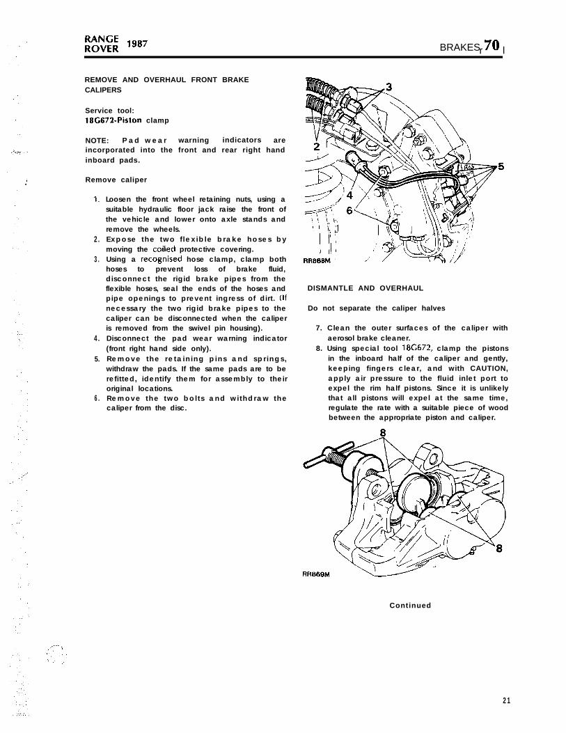
REMOVE AND OVERHAUL FRONT BRAKECALIPERS
Service tool:18G672-Piston clamp
NOTE: P a d w e a r warning indicators areincorporated into the front and rear right handinboard pads.
Remove caliper
1.
2.
3.
4.
5.
6.
Loosen the front wheel retaining nuts, using asuitable hydraulic floor jack raise the front ofthe vehicle and lower onto axle stands andremove the wheels.Expose the two f lex ib le brake hoses bymoving the coiied protective covering.Using a recognised hose clamp, clamp bothhoses to prevent loss of brake fluid,disconnect the rigid brake pipes from theflexible hoses, seal the ends of the hoses andpipe openings to prevent ingress of dirt. (Ifnecessary the two rigid brake pipes to thecaliper can be disconnected when the caliperis removed from the swivel pin housing).Disconnect the pad wear warning indicator(front right hand side only).Remove the re ta in ing p ins and spr ings ,withdraw the pads. If the same pads are to berefitted, identify them for assembly to theiroriginal locations.Remove the two bol t s and wi thdraw thecaliper from the disc.
DISMANTLE AND OVERHAUL
Do not separate the caliper halves
7. Clean the outer surfaces of the caliper withaerosol brake cleaner.
8. Using special tool 18G672, clamp the pistonsin the inboard half of the caliper and gently,keeping fingers clear, and with CAUTION,apply air pressure to the fluid inlet port toexpel the rim half pistons. Since it is unlikelythat all pistons will expel at the same time,regulate the rate with a suitable piece of woodbetween the appropriate piston and caliper.
RR669M
Continued
21
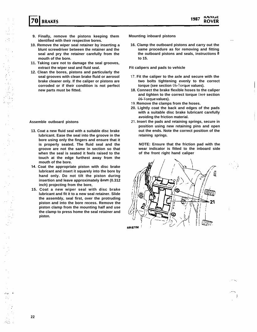
9. Finally, remove the pistons keeping themidentified with their respective bores.
10. Remove the wiper seal retainer by inserting ablunt screwdriver between the retainer and theseal and pry the retainer carefully from themouth of the bore.
11. Taking care not to damage the seal grooves,extract the wiper seal and fluid seal.
12. Clean the bores, pistons and particularly theseal grooves with clean brake fluid or aerosolbrake cleaner only. If the caliper or pistons arecorroded or if their condition is not perfectnew parts must be fitted.
Assemble outboard pistons
13. Coat a new fluid seal with a suitable disc brakelubricant. Ease the seal into the groove in thebore using only the fingers and ensure that itis properly seated. The fluid seal and thegroove are not the same in section so thatwhen the seal is seated it feels raised to thetouch at the edge furthest away from themouth of the bore.
14. Coat the appropriate piston with disc brakelubricant and insert it squarely into the bore byhand only. Do not tilt the piston duringinsertion and leave approximately 8mm (0.312inch) projecting from the bore,
15. Coat a new wiper seal with disc brakelubricant and fit it to a new seal retainer. Slidethe assembly, seal first, over the protrudingpiston and into the bore recess. Remove thepiston clamp from the mounting half and usethe clamp to press home the seal retainer andpiston.
Mounting inboard pistons. . .
16. Clamp the outboard pistons and carry out thesame procedure as for removing and fittingthe outboard pistons and seals, instructions 8to 15.
Fit calipers and pads to vehicle
17. Fit the caliper to the axle and secure with thetwo bolts tightening evenly to the correcttorque (see section 06-Torque values).
18. Connect the brake flexible hoses to the caliperand tighten to the correct torque (see section06.Torque values).
19. Remove the clamps from the hoses.20. Lightly coat the back and edges of the pads
with a suitable disc brake lubricant carefullyavoiding the friction material.
21. Insert the pads and retaining springs, secure inposition using new retaining pins and openout the ends. Note the correct position of theretaining springs.
NOTE: Ensure that the friction pad with thewear indicator is fitted to the inboard sideof the front right hand caliper
,.a’.,
).
22
22.
.’ 23.
24.
25.
26.
Reconnect the pad wear indicator electrical
plug.Bleed both the primary and secondary brakesystems. (Refer to page 4 for the brakebleeding procedure).When the foregoing instructions have beencompleted on all calipers, press the brakepedal firmly several times to locate the frictionpads.Fit the road wheels, remove the axle standsand finally tighten the road wheel nuts.Road test the vehicle, remembering that if newfriction pads have been fitted they are not‘bedde&in’ and may take several hundredmiles before the brakes are at maximumefficiency.
REMOVE AND OVERHAUL REAR BRAKE CALIPERS
Service tool:18C672-Piston clamp
Remove caliper
1.
2.
3.
.-I..
.’ ./4.
._ 5.
6.
Loosen the rear road wheel nuts and jack upthe rear of the vehicle, lower onto axle standsand remove the wheels.Using a recognised hose clamp, clamp theflexible brake hose above the rear axle, toprevent loss of fluid.Remove the brake pipe(s) from the rear brakecaliper(s). Seal the ends of the pipe to preventingress of dirt.Rear right hand caliper only, disconnect thepad wear indicator.Remove the retaining pins and springs andwithdraw the pads. If the same pads are to berefitted, identify them for assembly to theiroriginal locations.Remove the two bolts and withdraw thecaliper from the axle.
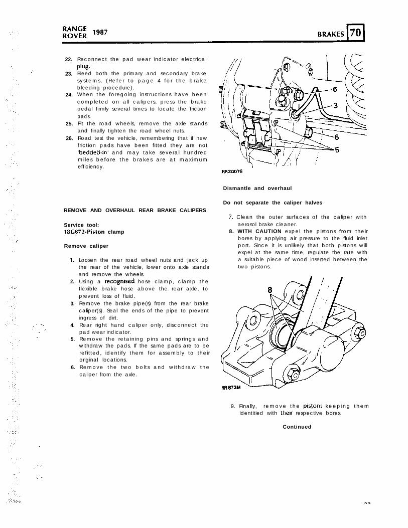
RR2007E
Dismantle and overhaul
Do not separate the caliper halves
7. Clean the outer surfaces of the caliper withaerosol brake cleaner.
8. WITH CAUTION expel the pistons from theirbores by applying air pressure to the fluid inletport. Since it is unlikely that both pistons willexpel at the same time, regulate the rate witha suitable piece of wood inserted between thetwo pistons.
9. Finally, remove the pistpns keeping themidentitied with their respective bores.
Continued
.
23
1987 RANGEROVER
10. Remove the wiper seal retainer by inserting ablunt screwdriver between the retainer and theseal and pry the retainer carefully from themouth of the bore.
I I. Taking care not to damage the seal grooves,extract the wiper seal and fluid seal.
12. Clean the bores, pistons and particularly theseal grooves with clean brake fluid or aerosolbrake cleaner only. If the caliper or pistons arecorroded or their condition is not perfect newparts must be fitted.
. .:
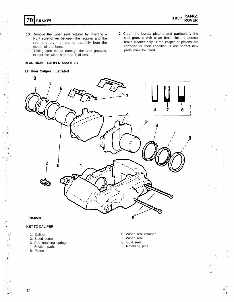
REAR BRAKE CALIPER ASSEMBLY
LH Rear Caliper illustrated
RRZOOBE
KEY TO CALIPER
1. Caliper 6. Wiper seal retainer2. Bleed screw 7. Wiper seal
8
3. Pad retaining springs4. Friction pads5. Piston
8. Fluid seal9. Retaining pins
24
BRAKES (70 1
13.,
14.
15
16
Coat a new fluid seal with a suitable disc brakelubricant. Ease the seal into the groove in thebore using only the fingers and ensure that itis properly seated. The f luid seal and thegroove are not the same in section so thatwhen the seal is seated it feels raised to thetouch at the edge furthest away from themouth of the bore.Coat the appropriate piston with a suitabledisc brake lubricant and insert it squarely intothe bore by hand only. Do not tilt the pistonduring insertion and leave approximately 8mm(0.312 inch) projecting from the bore.Coat a new wiper seal with a suitable discbrake lubricant and fit it to a new seal retainer.S l i d e t h e a s s e m b l y , s e a l f i r s t , o v e r t h eprotruding piston and into the bore recess.Using special tool 18G672-piston clamp, presshome the seal retainer and piston.
Mounting inboard piston
17. Carry out the same procedure as for removingand fitting the outboard piston and seals,instructions 8 to 16.
Fit calipers and pads to vehicle
18.’
19.
20.
Fit the caliper to the axle and secure with thetwo bolts tightening evenly to the correcttorque (see section 06-Torque values).Connect the brake pipes to the calipers andremove the clamp from the flexible brake hoseabove the rear axles, see section 06-Torquevalues for brake pipe to caliper tighteningtorque.Lightly coat the back and edges of the padswith disc brake lubricant carefully avoiding thefriction material.
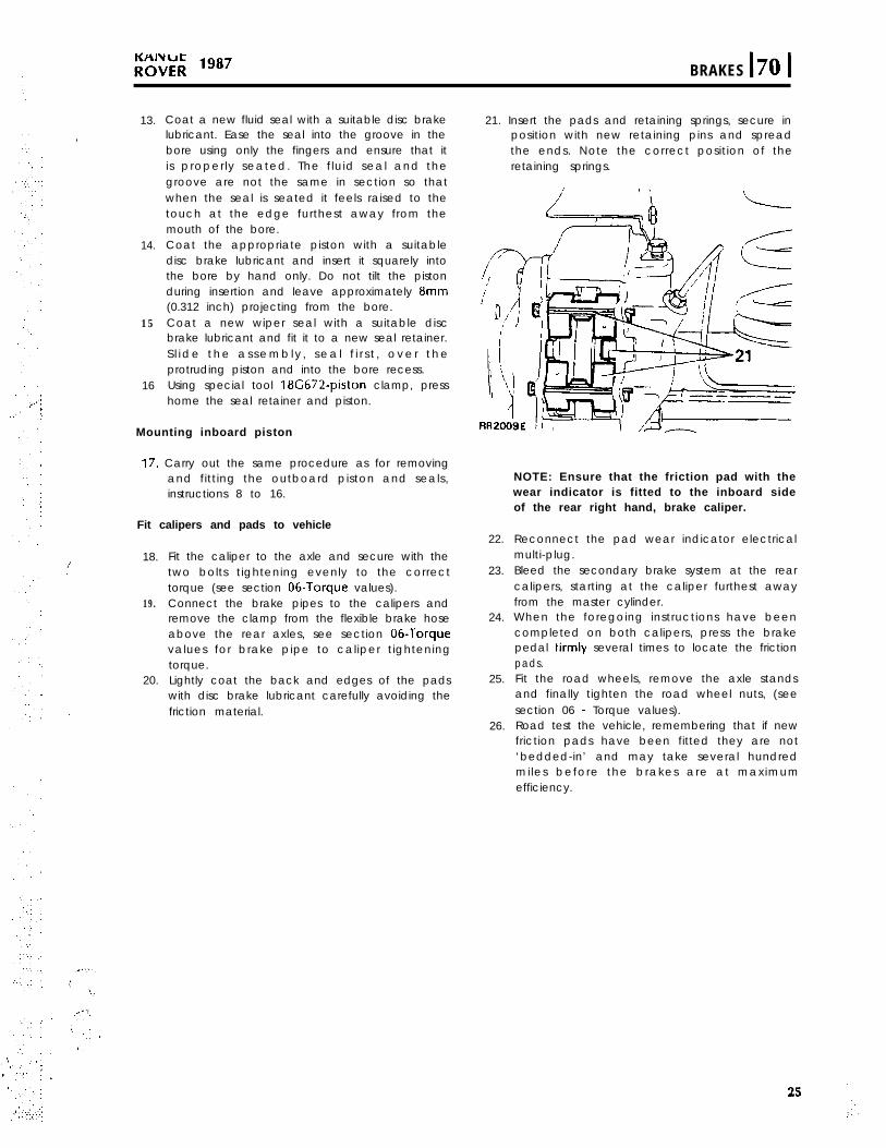
21. Insert the pads and retaining springs, secure inposition with new retaining pins and spreadthe ends. Note the correct position of theretaining springs.
NOTE: Ensure that the friction pad with thewear indicator is fitted to the inboard sideof the rear right hand, brake caliper.
22.
23.
24.
25.
26.
Reconnect the pad wear indicator electricalmulti-plug.Bleed the secondary brake system at the rearcalipers, starting at the caliper furthest awayfrom the master cylinder.When the foregoing instructions have beencompleted on both calipers, press the brakepedal tirmly several times to locate the frictionpads.Fit the road wheels, remove the axle standsand finally tighten the road wheel nuts, (seesection 06 - Torque values).Road test the vehicle, remembering that if newfriction pads have been fitted they are not‘bedded-in’ and may take several hundredmiles before the brakes are at maximumefficiency.
RANGElg8’ ROVER
PARKING BRAKE LEVER
Remove and refit
Removing
1.2.
3.
4.
5.
6.
7.
6.
9.
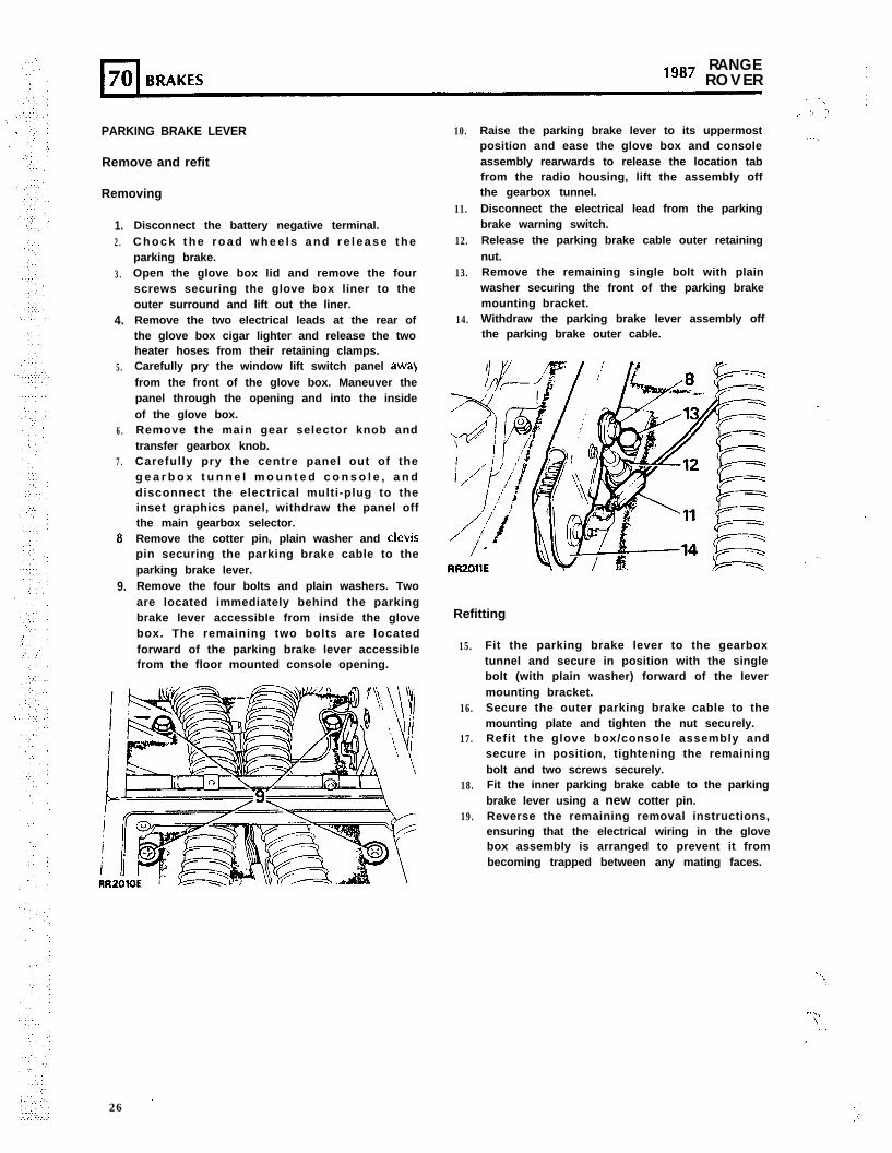
Disconnect the battery negative terminal.C h o c k t h e r o a d w h e e l s a n d r e l e a s e t h eparking brake.Open the glove box lid and remove the fourscrews securing the glove box liner to theouter surround and lift out the liner.Remove the two electrical leads at the rear ofthe glove box cigar lighter and release the twoheater hoses from their retaining clamps.Carefully pry the window lift switch panel awa)from the front of the glove box. Maneuver thepanel through the opening and into the insideof the glove box.Remove the main gear selector knob andtransfer gearbox knob.Carefully pry the centre panel out of theg e a r b o x t u n n e l m o u n t e d c o n s o l e , a n ddisconnect the electrical multi-plug to theinset graphics panel, withdraw the panel offthe main gearbox selector.Remove the cotter pin, plain washer and clevispin securing the parking brake cable to theparking brake lever.Remove the four bolts and plain washers. Twoare located immediately behind the parkingbrake lever accessible from inside the glovebox. The remaining two bolts are locatedforward of the parking brake lever accessiblefrom the floor mounted console opening.
26 .
10.
11.
12.
13.
14.
Raise the parking brake lever to its uppermostposition and ease the glove box and consoleassembly rearwards to release the location tabfrom the radio housing, lift the assembly offthe gearbox tunnel.Disconnect the electrical lead from the parkingbrake warning switch.Release the parking brake cable outer retainingnut.
: 1::.
_.._.
Remove the remaining single bolt with plainwasher securing the front of the parking brakemounting bracket.Withdraw the parking brake lever assembly offthe parking brake outer cable.
Refitting
15.
16.
17.
18.
19.
Fit the parking brake lever to the gearboxtunnel and secure in position with the singlebolt (with plain washer) forward of the levermounting bracket.Secure the outer parking brake cable to themounting plate and tighten the nut securely.Refit the glove box/console assembly andsecure in position, tightening the remainingbolt and two screws securely.Fit the inner parking brake cable to the parkingbrake lever using a new cotter pin.Reverse the remaining removal instructions,ensuring that the electrical wiring in the glovebox assembly is arranged to prevent it frombecoming trapped between any mating faces.
. ̂ .?
-....‘$. .
_.
.
‘.
‘.
,’ .’
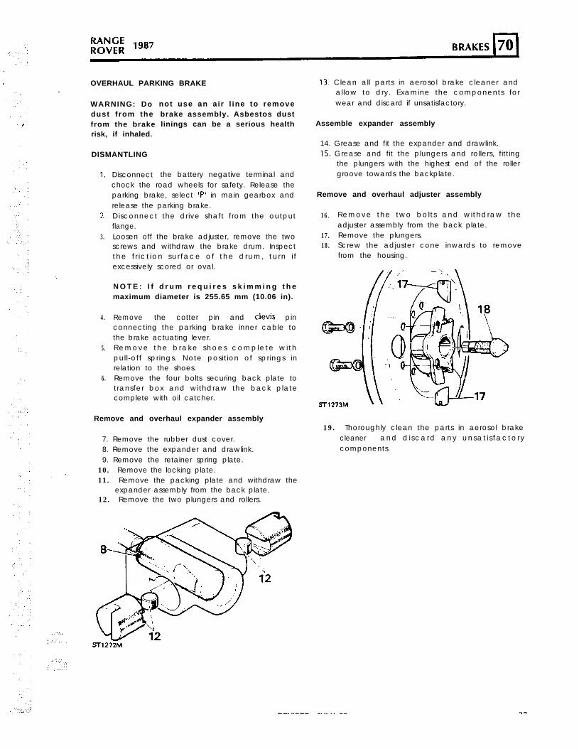
OVERHAUL PARKING BRAKE
WARNING: Dodust f rom thefrom the brakerisk, if inhaled.
DISMANTLING
1.
2
3.
4.
5.
6.
Disconnect the battery negative terminal and
not use an a i r l ine to removebrake assembly. Asbestos dustlinings can be a serious health
chock the road wheels for safety. Release theparking brake, select ‘P’ in main gearbox andrelease the parking brake.Disconnect the drive shaft from the outputflange.Loosen off the brake adjuster, remove the twoscrews and withdraw the brake drum. Inspectthe f r ict ion sur face of the drum, turn i fexcessively scored or oval.
N O T E : I f d r u m r e q u i r e s s k i m m i n g t h emaximum diameter is 255.65 mm (10.06 in).
Remove the cotter pin and clevis pinconnecting the parking brake inner cable tothe brake actuating lever.Remove the brake shoes complete wi thpull-off springs. Note position of springs inrelation to the shoes.Remove the four bolts securing back plate totransfer box and withdraw the back platecomplete with oil catcher.
Remove and overhaul expander assembly
7. Remove the rubber dust cover.8. Remove the expander and drawlink.9. Remove the retainer spring plate.10. Remove the locking plate.11. Remove the packing plate and withdraw the
expander assembly from the back plate.12. Remove the two plungers and rollers.
13. Clean all parts in aerosol brake cleaner andallow to dry. Examine the components forwear and discard if unsatisfactory.
Assemble expander assembly
14. Grease and fit the expander and drawlink.15. Grease and fit the plungers and rollers, fitting
the plungers with the highest end of the rollergroove towards the backplate.
Remove and overhaul adjuster assembly
16.
17.18.
Remove the two bolts and withdraw theadjuster assembly from the back plate.Remove the plungers.Screw the adjuster cone inwards to removefrom the housing.
19. Thoroughly clean the parts in aerosol brakecleaner and d i scard any unsat i s factorycomponents.
REVISED: JULY 88 27
‘,(.
i. ..“\
" !
:,
RANGE“*’ ROVER
,.
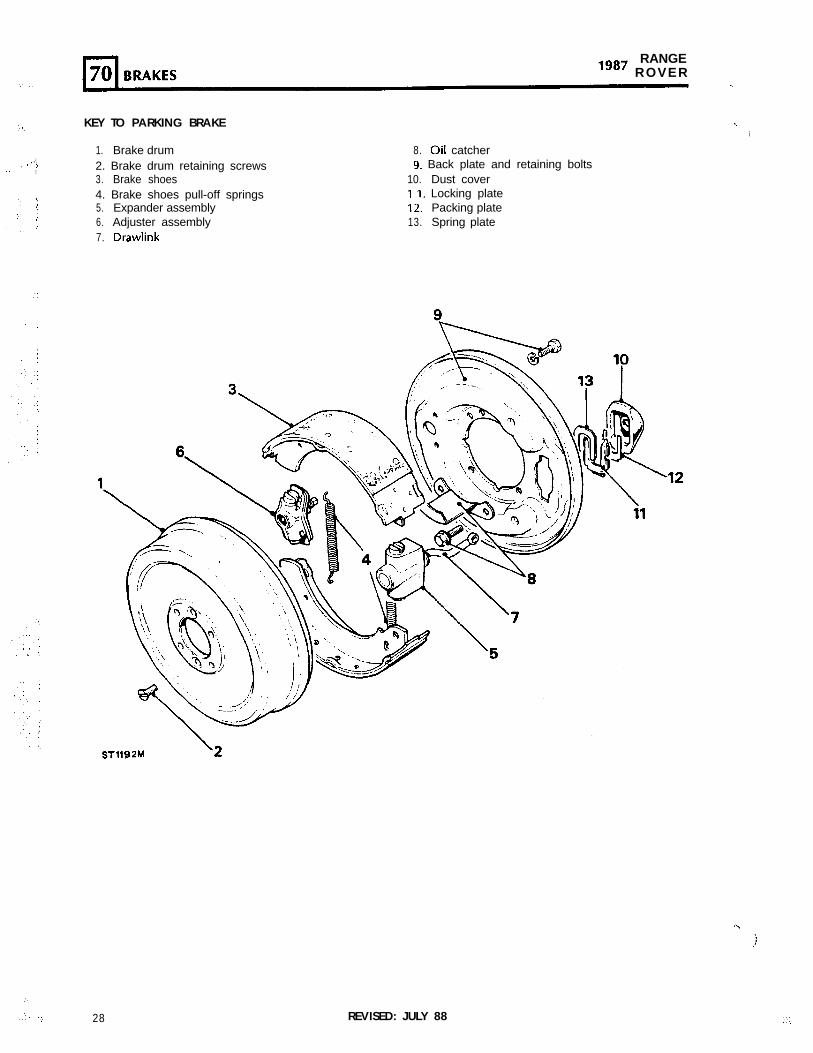
KEY TO PARKING BRAKE
1. Brake drum2. Brake drum retaining screws3. Brake shoes4. Brake shoes pull-off springs5. Expander assembly6. Adjuster assembly7. Drawlink
8. oil catcher9. Back plate and retaining bolts
10. Dust coverI I. Locking plate12. Packing plate13. Spring plate
-.
i
I.)
,j
:.
..,A’ ‘1. 28 REVISED: JULY 88
..:
‘...’ 4
. I
.
:
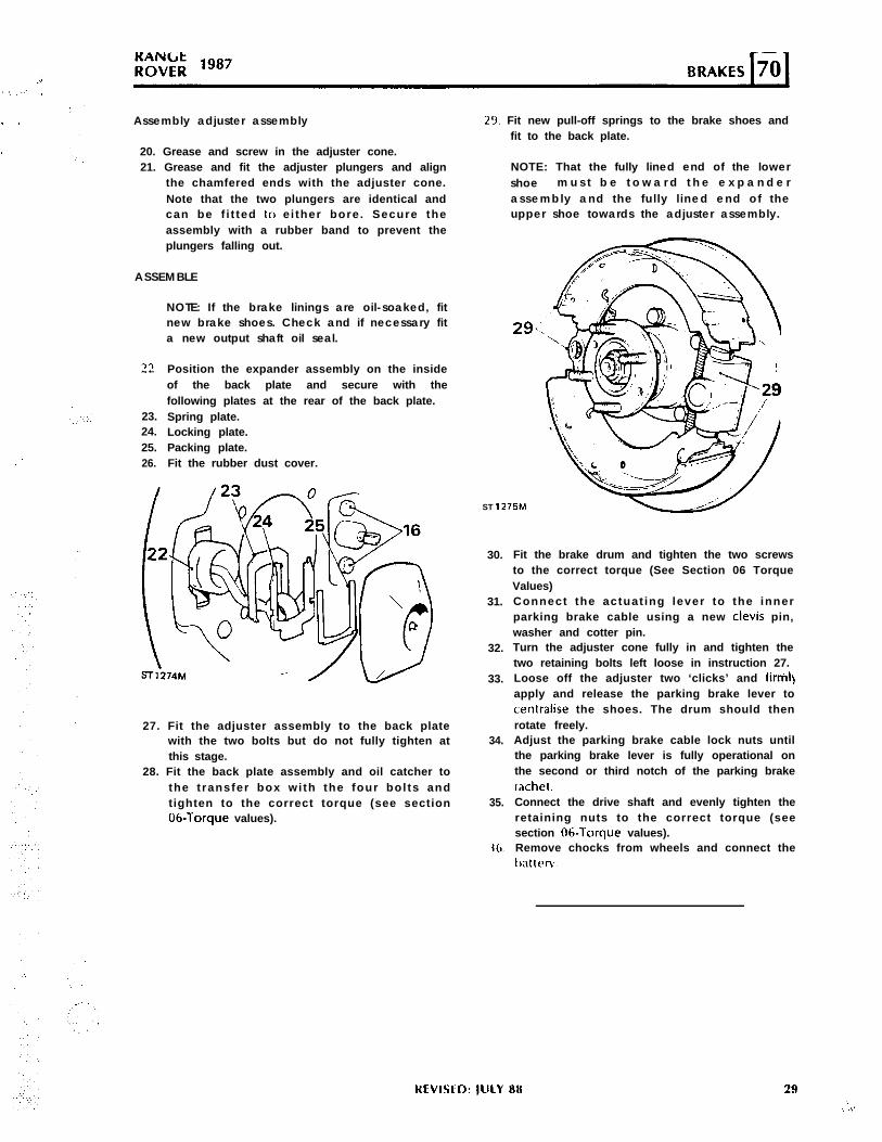
Assembly adjuster assembly
20. Grease and screw in the adjuster cone.21. Grease and fit the adjuster plungers and align
the chamfered ends with the adjuster cone.Note that the two plungers are identical andcan be f i t ted lo e i ther bore. Secure theassembly with a rubber band to prevent theplungers falling out.
ASSEMBLE
22.
23.24.25.26.
NOTE: If the brake linings are oil-soaked, fitnew brake shoes. Check and if necessary fita new output shaft oil seal.
Position the expander assembly on the insideof the back plate and secure with thefollowing plates at the rear of the back plate.Spring plate.Locking plate.Packing plate.Fit the rubber dust cover.
27. Fit the adjuster assembly to the back platewith the two bolts but do not fully tighten atthis stage.
28. Fit the back plate assembly and oil catcher tothe t ransfer box wi th the four bol ts andtighten to the correct torque (see section06-Torque values).
29. Fit new pull-off springs to the brake shoes andfit to the back plate.
NOTE: That the fully lined end of the lowershoe m u s t b e t o w a r d t h e e x p a n d e rassembly and the ful ly l ined end of theupper shoe towards the adjuster assembly.
29<
ST 1275M
30.
31.
32.
33.
34.
35.
36
Fit the brake drum and tighten the two screwsto the correct torque (See Section 06 TorqueValues)Connect the actuat ing lever to the innerparking brake cable using a new clevis pin,washer and cotter pin.Turn the adjuster cone fully in and tighten thetwo retaining bolts left loose in instruction 27.Loose off the adjuster two ‘clicks’ and fimil)apply and release the parking brake lever tocentralise the shoes. The drum should thenrotate freely.Adjust the parking brake cable lock nuts untilthe parking brake lever is fully operational onthe second or third notch of the parking brakerachet.Connect the drive shaft and evenly tighten theretaining nuts to the correct torque (seesection 06-Torque values).Remove chocks from wheels and connect thet)alteW.
HEVIWD: IULY HH 29‘.
I, .i’
l-l RANGE70 BRAKES “*’ ROVER
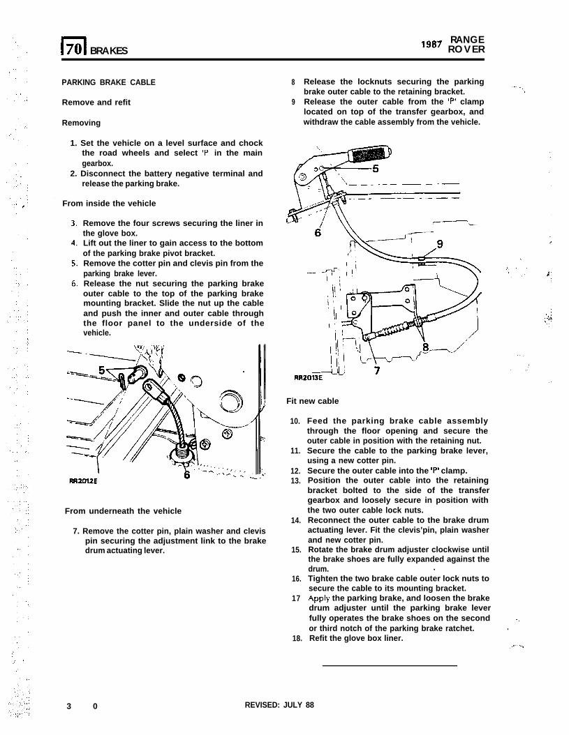
PARKING BRAKE CABLE
Remove and refit
Removing
1. Set the vehicle on a level surface and chockthe road wheels and select ‘P’ in the maingearbox.
2. Disconnect the battery negative terminal andrelease the parking brake.
From inside the vehicle
Remove the four screws securing the liner inthe glove box.Lift out the liner to gain access to the bottomof the parking brake pivot bracket.Remove the cotter pin and clevis pin from theparking brake lever.Release the nut securing the parking brakeouter cable to the top of the parking brakemounting bracket. Slide the nut up the cableand push the inner and outer cable throughthe floor panel to the underside of thevehicle.
From underneath the vehicle
7. Remove the cotter pin, plain washer and clevispin securing the adjustment link to the brakedrum actuating lever.
3 0
8
9
Release the locknuts securing the parkingbrake outer cable to the retaining bracket.
-_. ,., iRelease the outer cable from the ‘P’ clamplocated on top of the transfer gearbox, andwithdraw the cable assembly from the vehicle.
Fit new cable
10.
11.
12.13.
14.
15.
16.
17
18.
Feed the parking brake cable assemblythrough the floor opening and secure theouter cable in position with the retaining nut.Secure the cable to the parking brake lever,using a new cotter pin.Secure the outer cable into the ‘P’ clamp.Position the outer cable into the retainingbracket bolted to the side of the transfergearbox and loosely secure in position withthe two outer cable lock nuts.Reconnect the outer cable to the brake drumactuating lever. Fit the clevis’pin, plain washerand new cotter pin.Rotate the brake drum adjuster clockwise untilthe brake shoes are fully expanded against thedrum. .Tighten the two brake cable outer lock nuts tosecure the cable to its mounting bracket.Apply the parking brake, and loosen the brakedrum adjuster until the parking brake leverfully operates the brake shoes on the secondor third notch of the parking brake ratchet.Refit the glove box liner.
..,!
,.,.’ I..
REVISED: JULY 88
,a,
i’
‘,
,’
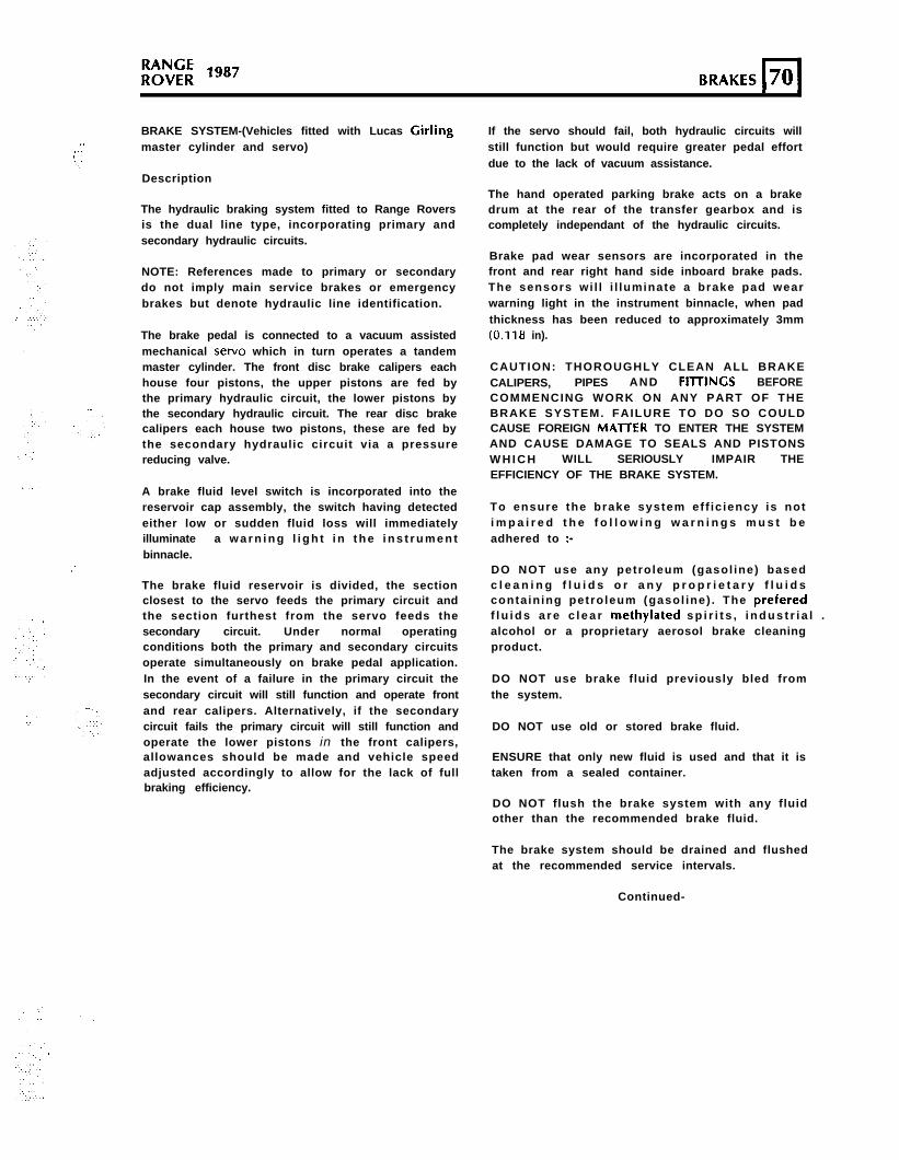
BRAKE SYSTEM-(Vehicles fitted with Lucas Cirlingmaster cylinder and servo)
Description
The hydraulic braking system fitted to Range Roversis the dual line type, incorporating primary andsecondary hydraulic circuits.
NOTE: References made to primary or secondarydo not imply main service brakes or emergencybrakes but denote hydraulic line identification.
The brake pedal is connected to a vacuum assistedmechanical servo which in turn operates a tandemmaster cylinder. The front disc brake calipers eachhouse four pistons, the upper pistons are fed bythe primary hydraulic circuit, the lower pistons bythe secondary hydraulic circuit. The rear disc brakecalipers each house two pistons, these are fed bythe secondary hydraulic circuit via a pressurereducing valve.
A brake fluid level switch is incorporated into thereservoir cap assembly, the switch having detectedeither low or sudden fluid loss will immediatelyilluminate a w a r n i n g l i g h t i n t h e i n s t r u m e n tbinnacle.
The brake fluid reservoir is divided, the sectionclosest to the servo feeds the primary circuit andthe section furthest from the servo feeds thesecondary circuit. Under normal operatingconditions both the primary and secondary circuitsoperate simultaneously on brake pedal application.In the event of a failure in the primary circuit thesecondary circuit will still function and operate frontand rear calipers. Alternatively, if the secondarycircuit fails the primary circuit will still function andoperate the lower pistons in the front calipers,allowances should be made and vehicle speedadjusted accordingly to allow for the lack of fullbraking efficiency.
If the servo should fail, both hydraulic circuits willstill function but would require greater pedal effortdue to the lack of vacuum assistance.
The hand operated parking brake acts on a brakedrum at the rear of the transfer gearbox and iscompletely independant of the hydraulic circuits.
Brake pad wear sensors are incorporated in thefront and rear right hand side inboard brake pads.The sensors wi l l i l luminate a brake pad wearwarning light in the instrument binnacle, when padthickness has been reduced to approximately 3mm(0.11&i in).
CAUTION: THOROUGHLY CLEAN ALL BRAKECALIPERS, PIPES AND FllTlNGS BEFORECOMMENCING WORK ON ANY PART OF THEBRAKE SYSTEM. FAILURE TO DO SO COULDCAUSE FOREIGN MAlTER TO ENTER THE SYSTEMAND CAUSE DAMAGE TO SEALS AND PISTONSW H I C H WILL SERIOUSLY IMPAIR THEEFFICIENCY OF THE BRAKE SYSTEM.
To ensure the brake system ef f ic iency is noti m p a i r e d t h e f o l l o w i n g w a r n i n g s m u s t b eadhered to :-
DO NOT use any petroleum (gasol ine) basedc l e a n i n g f l u i d s o r a n y p r o p r i e t a r y f l u i d scontaining petroleum (gasol ine) . The preferedf l u i d s a r e c l e a r methylated s p i r i t s , i n d u s t r i a l .alcohol or a proprietary aerosol brake cleaningproduct.
DO NOT use brake fluid previously bled fromthe system.
DO NOT use old or stored brake fluid.
ENSURE that only new fluid is used and that it istaken from a sealed container.
DO NOT flush the brake system with any fluidother than the recommended brake fluid.
The brake system should be drained and flushedat the recommended service intervals.
Continued-
LUCAS GIRLING MASTER CYLINDER AND SERVO - ADDITION: IULY 87 31
. ..$.: p
.
PRIMARY HYDRAULIC CIRCUIT
SECONDARY HYDRAULICCIRCUIT
RR2226M.-.
‘I
.....
;
.:
32 ’ LUCAS GIRLING MASTER CYLINDER AND SERVO - ADDITION: JULY 87 : . .
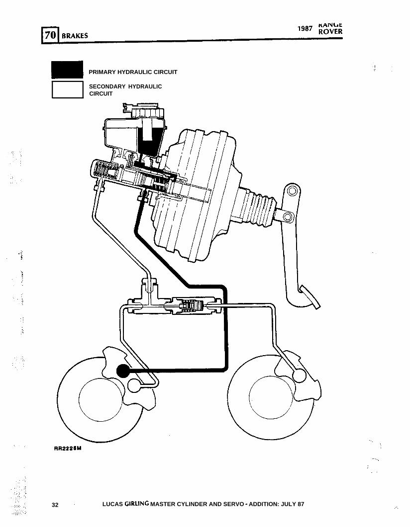
RR2222E
BRAKE PIPE LAYOUTLeft hand drive
HOSES
I. Front left hand flexible hoses.2. Front right hand flexible hoses.3. Intermediate flexible hose.
n-.. . . PIPES
_.4. Feed to front left hand hose connector.5. Feed to front right hand hose connector.6. Feed to front left hand caliper.
7. Feed to front right hand caliper.8. Feed to rear left hand caliper.9. Feed to rear right hand caliper.
10. Feed to two way connector.11. Feed to intermediate hose.12. Two way connector.13. Three way connector.14. Pressure reducing valve.
Continued
LUCAS CIRLING MASTER CYLINDER AND SERVO - ADDITION: JULY 87 33. “....: :.
1987 RANGEROVER
WARNING: Some components on the vehiclesuch as gaskets and fr ict ion surfaces (brakelinings, clutch discs, or automatic transmissionbrake bands), may contain asbestos. Inhalingasbestos dust is dangerous to your health andthe fol lowing essent ia l precaut ions must beobserved :-
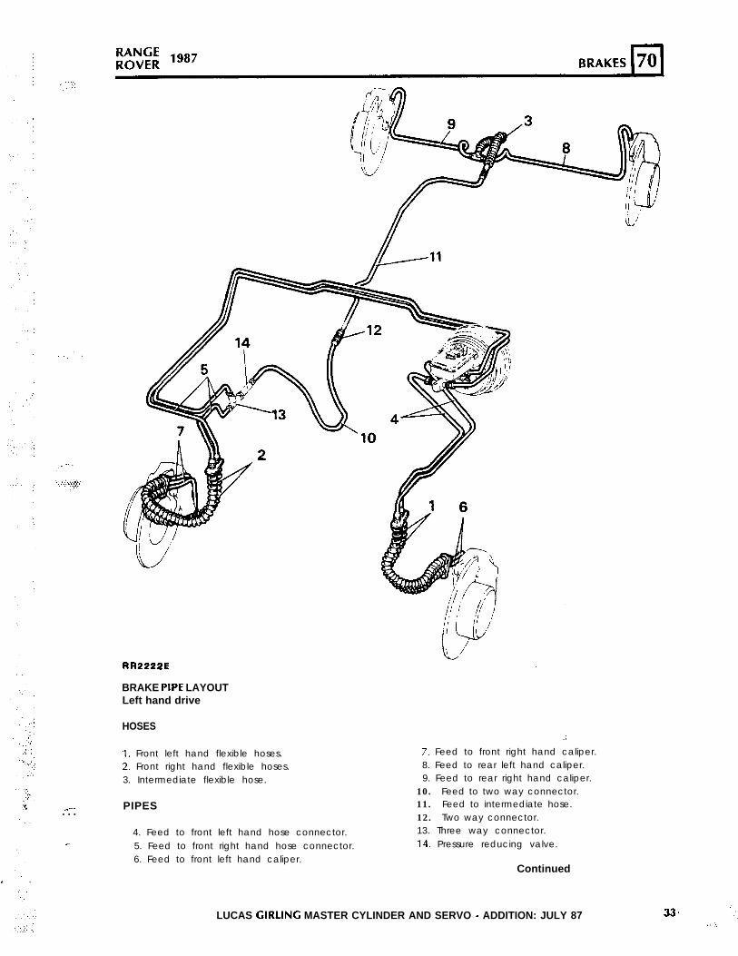
NOTE: When bleeding the system commencew i t h t h e c a l i p e r f u r t h e s t f r o m t h e m a s t e rcylinder and bleed from the screw on the sameside as the fluid inlet pipes, then close the screwand bleed from the screw on the opposite sideof the same caliper. Tighten the bleed screws tothe correct torque value. See section 06
* W o r k o u t o f d o o r s o r i n a w e l l v e n t i l a t e darea and wear a protective mask.
Bleeding1.
* D u s t f o u n d o n t h e v e h i c l e o r p r o d u c e dd u r i n g w o r k o n t h e v e h i c l e s h o u l d b eremoved by vacuuming or by using a welldampened cloth and not by blowing. 2.
* Dust waste should be dampened, placed in asealed container and marked to ensure safedisposal.
1 If any cutting, drill ing etc, is attempted onmaterials containing asbestos the itemshould be dampened and only hand tools orlow speed power tools used.
3.
4.5.
BRAKES
Bleed 6.
The hydraulic system comprises two completelyindependent circuits. The rear calipers and thelower p i s tons in the f ront ca l ipers fo rm thesecondary circuit, while the upper pistons in thefront calipers form the primary circuit, The followingprocedure covers bleeding the complete system,but it is permissible to bleed one circuit only ifdisconnections are limited to that circuit.
7.
Bleeding will be assisted if the engine is run or avacuum supply is connected to the servo.
WARNING: IF THE ENGINE IS RUNNING DURINGTHE BRAKE BLEEDING PROCESS ENSURE THATNEUTRAL OR PARK IS SELECTED IN THE MAINGEARBOX AND THAT THE PARKING BRAKE ISAPPLIED.
When bleeding any part of the secondary circuit,almost full brake pedal travel is available. Whenbleeding the primary circuit only, brake pedal travelwill be restricted to approximately half.
Fill-the fluid reservoir with the correct grade offluid, see section 09 lubricants and fluids.N O T E : T h e c o r r e c t f l u i d l e v e l m u s t b emainta ined throughout the procedure ofbleeding.Connect a bleed hose to the bleed screw onthe rear caliper furthest from the mastercylinder.Submerge the free end of the bleed hose in acontainer of clean brake fluid.Loosen the bleed screw l/2-3/4 of a turn.Operate the brake pedal fully and allow toreturn.NOTE: Allow at least five seconds to elapsewith the foot right off the pedal to ensurethat t h e p i s t o n s f u l l y r e t u r n b e f o r eoperating the pedal again.
Repeat 5 unti l f luid clear of air bubblesappears in the container, then keeping thepedal fully depressed, tighten the bleed screw.Remove the bleed hose and replace the dustcap on the bleed screw.
. . . . .
. . ‘\
’
34 LUCAS GIRLING MASTER CYLINDER AND SERVO - ADDITION: IULY 87.’
‘.
I
:
,’ .,’
‘.
,.,
: .:
;;;z; 1 9 8 7 B R A K E S 70\
8.9.
10.
11.
12.
13.
Repeat 1 to 7 fr the other rear caliper.Remove the front wheel on the side furthestfrom the master cylinder.Connect a bleed hose to the primary bleedscrew on the front caliper furthest from themaster cylinder.Connect a bleed hose to the secondary bleedscrew on the same side of the caliper as theprimary screw.Repeat 3 to 7 for the front caliper, bleedingfrom the two screws simultaneously.Connect a bleed hose to the other screw onthe front caliper furthest from the mastercylinder.
14.
15.16.
Repeat 3 to 7 for the second secondary screwon the front caliper.Refit the front wheel.Repeat 9 to 15 for the front caliper nearest themaster cylinder.
MASTER CYLINDER - Lucas Girling- Type 25.4mm AS/AS
Remove, overhaul and refit
Removing
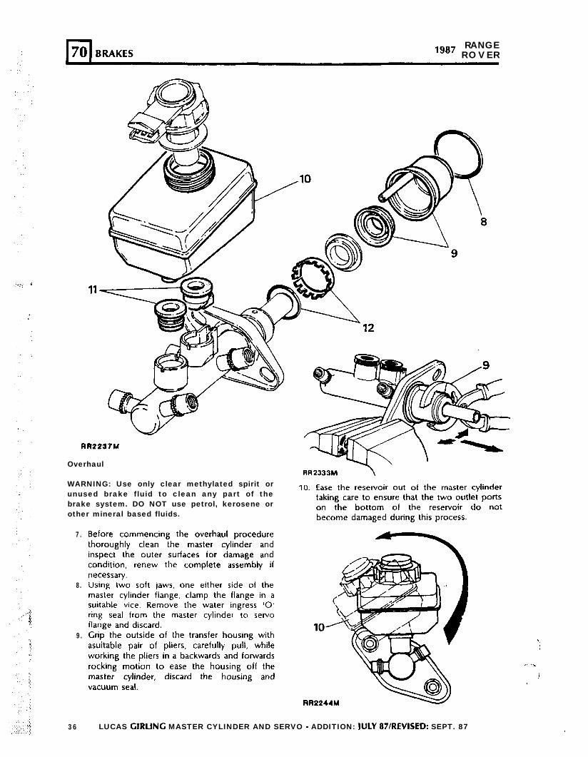
1.2.
3.
4.
5.
6.
Disconnect the battery negative terminal.Place a suitable container under the mastercylinder to catch any brake fluid which mayseep from the cylinder when the brake pipesare disconnected from the outlet ports.Thoroughly clean the immediate area aroundall outlet ports. Remove each of the brakepipes from the master cylinder in turn, sealingeach pipe and outlet port with suitable plugsas they are disconnected, to prevent ingress offoreign matter and excessive fluid loss.Disconnect the electrical plug from the low
fluid switch located on the reservoir cap.Remove the two nuts securing the mastercylinder to the servo unit remove also thespring and plain washers.Detach the the master cylinder from the servo,remove the reservoir cap and drain the brakefluid into a suitable container.
6
6
WARNING: Do not use brake f lu id previouslyd r a i n e d o r b l e d f r o m t h e s y s t e m . C a r e f u l l ydispose of unwanted fluid, if stored in a sealedcontainer, ensure that the container is markedUSED BRAKE FLUID.
Continued
LUCAS GIRLING MASTER CYLINDER AND SERVO - ADDITION: JULY 87IREVISED: SEPT. 87 35
RANGElg8’ R O V E R
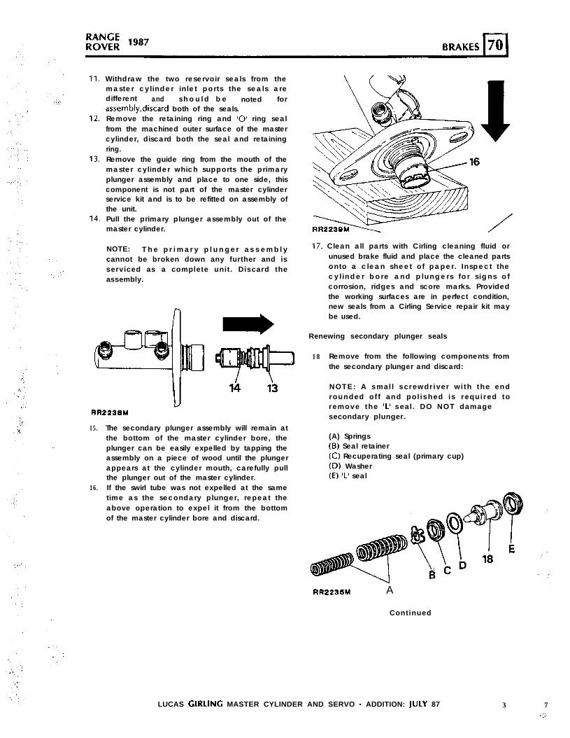
RR2237M
Overhaul
WARNING: Use only clear methylated spirit orunused brake fluid to clean any part of thebrake system. DO NOT use petrol, kerosene orother mineral based fluids.
7.
8.
9.
36
Before commencing the overhaul procedurethoroughly clean the master cylinder andinspect the outer surfaces for damage andcondition, renew the complete assembly ifnecessary.Using two soft jaws, one either side of themaster cylinder flange, clamp the flange in asuitable vice. Remove the water ingress ‘0’ring seal from the master cylinder to servoflange and discard.Grip the outside of the transfer housing withasuitable pair of pliers, carefully pull, whileworking the pliers in a backwards and forwardsrocking motion to ease the housing off themaster cylinder, discard the housing andvacuum seal.
10. Ease the reservoir out of the master cylindertaking care to ensure that the two outlet portson the bottom of the reservoir do notbecome damaged during this process.
RR2244M
LUCAS GIRLING MASTER CYLINDER AND SERVO - ADDITION: ]UlY 87/REVISED: SEPT. 87
‘.\I
.., .\
!I
Withdraw the two reservoir seals from themaster cyl inder inlet ports the seals aredifferent and s h o u l d b e noted forassembly,discard both of the seals.Remove the retaining ring and ‘0’ ring sealfrom the machined outer surface of the mastercylinder, discard both the seal and retainingring.Remove the guide ring from the mouth of themaster cylinder which supports the primaryplunger assembly and place to one side, thiscomponent is not part of the master cylinderservice kit and is to be refitted on assembly ofthe unit.Pull the primary plunger assembly out of themaster cylinder. /
NOTE: T h e p r i m a r y p l u n g e r a s s e m b l ycannot be broken down any further and isserviced as a complete unit. Discard theassembly.
”
RR2238M
15.
16.
The secondary plunger assembly will remain atthe bottom of the master cylinder bore, theplunger can be easily expelled by tapping theassembly on a piece of wood until the plungerappears at the cylinder mouth, carefully pullthe plunger out of the master cylinder.If the swirl tube was not expelled at the sametime as the secondary plunger, repeat theabove operation to expel it from the bottomof the master cylinder bore and discard.
17. Clean all parts with Cirling cleaning fluid orunused brake fluid and place the cleaned partsonto a clean sheet of paper. Inspect thecy l inder bore and p lungers fo r s igns o fcorrosion, ridges and score marks. Providedthe working surfaces are in perfect condition,new seals from a Cirling Service repair kit maybe used.
Renewing secondary plunger seals
18 Remove from the following components fromthe secondary plunger and discard:
NOTE: A smal l screwdriver wi th the endrounded of f and pol ished is required toremove the ‘L’ seal . DO NOT damagesecondary plunger.
(A) Springs(B) Seal retainer(C) Recuperating seal (primary cup)(D) Washer(E) ‘L’ seal
RR2233M A
Continued
LUCAS GIRLING MASTER CYLINDER AND SERVO - ADDITION: JULY 87 3 7I.:..
.>
.:
‘.
,:;.,
,:
‘/..*. 1:
‘...(.’ .‘.
. .:.
i:,. .
.’
X
‘.
,_ .’
::.
.*
. . . +
*
:
,’ ,_:.
,’*’
.’
..:. , :
‘,
:
.:... ~‘,
RANGE“* ROVER
. . . .
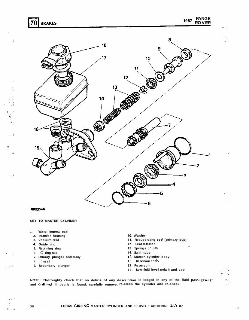
KEY TO MASTER CYLINDER
1. Water ingress seal2. Transfer housing3. Vacuum seal4. Guide ring5. Retaining ring6. ‘0’ ring seal7. Primary plunger assembly8. ‘L’ seal9. Secondary plunger
10. WasherIl. Recuperating seal (primary cup)12. Seal retainer13. Springs (2 off)
. .
14. Swirl tubeIS. Master cylinder body16. Reservoir seals17. Reservoir18. Low fluid level switch and cap
NOTE: Thoroughly check that no debris of any description is lodged in any of the fluid passagewaysand drillings. If debris is found, carefully remove, re-clean the cylinder and re-check.
.. -,,.I
.’
38 ’ LUCAS GIRLING MASTER CYLINDER AND SERVO - ADDITION: JULY 87 ::
.’
.:
,,r
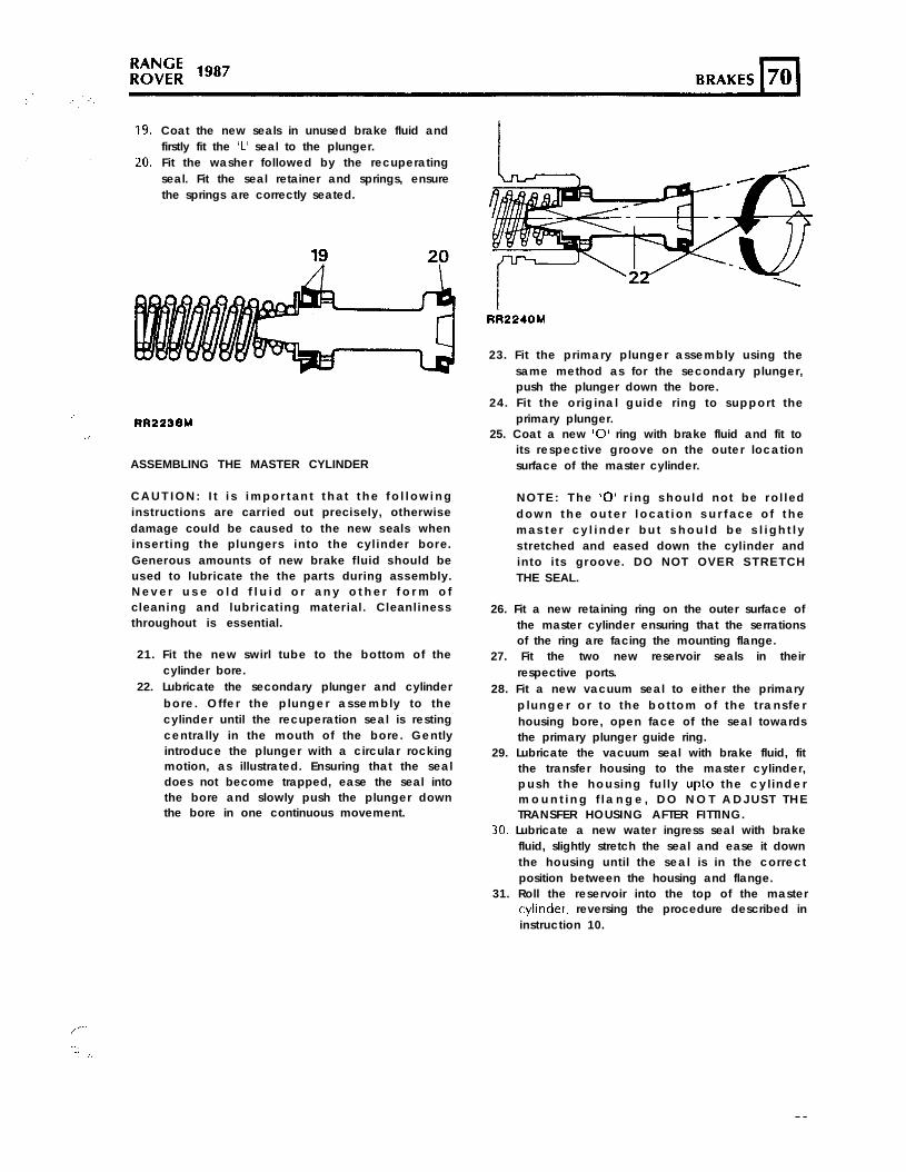
‘1.‘. :.
Coat the new seals in unused brake fluid andfirstly fit the ‘L’ seal to the plunger.Fit the washer followed by the recuperatingseal. Fit the seal retainer and springs, ensurethe springs are correctly seated.
RR223BM
ASSEMBLING THE MASTER CYLINDER
C A U T I O N : I t i s i m p o r t a n t t h a t t h e f o l l o w i n ginstructions are carried out precisely, otherwisedamage could be caused to the new seals wheninserting the plungers into the cylinder bore.Generous amounts of new brake fluid should beused to lubricate the the parts during assembly.N e v e r u s e o l d f l u i d o r a n y o t h e r f o r m o fcleaning and lubricating material. Cleanlinessthroughout is essential.
21. Fit the new swirl tube to the bottom of thecylinder bore.
22. Lubricate the secondary plunger and cylinderbore. Offer the plunger assembly to thecylinder until the recuperation seal is restingcentrally in the mouth of the bore. Gentlyintroduce the plunger with a circular rockingmotion, as illustrated. Ensuring that the sealdoes not become trapped, ease the seal intothe bore and slowly push the plunger downthe bore in one continuous movement.
RR2240M
23. Fit the primary plunger assembly using thesame method as for the secondary plunger,push the plunger down the bore.
24. Fi t the original guide r ing to support theprimary plunger.
25. Coat a new ‘0’ ring with brake fluid and fit toits respective groove on the outer locationsurface of the master cylinder.
NOTE: The ‘0’ r ing should not be rol ledd o w n t h e o u t e r l o c a t i o n s u r f a c e o f t h em a s t e r c y l i n d e r b u t s h o u l d b e s l i g h t l ystretched and eased down the cylinder andinto its groove. DO NOT OVER STRETCHTHE SEAL.
26. Fit a new retaining ring on the outer surface ofthe master cylinder ensuring that the serrationsof the ring are facing the mounting flange.
27. Fit the two new reservoir seals in theirrespective ports.
28. Fit a new vacuum seal to either the primaryplunger or to the bot tom of the t rans ferhousing bore, open face of the seal towardsthe primary plunger guide ring.
29. Lubricate the vacuum seal with brake fluid, fitthe transfer housing to the master cylinder,push the hous ing fu l ly upto the cy l inderm o u n t i n g f l a n g e , D O N O T A D J U S T T H ETRANSFER HOUSING AFTER FITTING.
30. Lubricate a new water ingress seal with brakefluid, slightly stretch the seal and ease it downthe housing until the seal is in the correctposition between the housing and flange.
31. Roll the reservoir into the top of the mastercylrnder. reversing the procedure described ininstruction 10.
LUCAS GIRLINC MASTER CYLINDER AND SERVO - ADDITION: JULY 87 39
1987 RANGEROVER
32. Fit the master cylinder to the servo fit theplain and spring washers and secure inposition with the two nuts. Tighten to thespecified Torque value- see section 06.
33. Fit the brake pipes to the master cylinder andtighten to the specified Torque value- seesection 06
34. Top-up the master cylinder with the correctgrade of brake fluid (see section 09) bleed thebrake systems.
WARNING: Do not use b rake f lu idpreviously drained or bled from the system.Carefully dispose of unwanted fluid, ifstored in a sealed container, ensure thatthe container is marked USED BRAKE FLUID.
35. Fit the cap with combined low level fluidswitch and reconnect the electrical lead.Re-connect the battery.
SERVO ASSEMBLY . .
Remove and refitI
NOTE: Other than replacing the filter,non-return valve and grommet, the servo isnot a serviceable component, in the eventof failure or damage fit a new unit.
Removing
1.2.
3.
4.
5.
6.
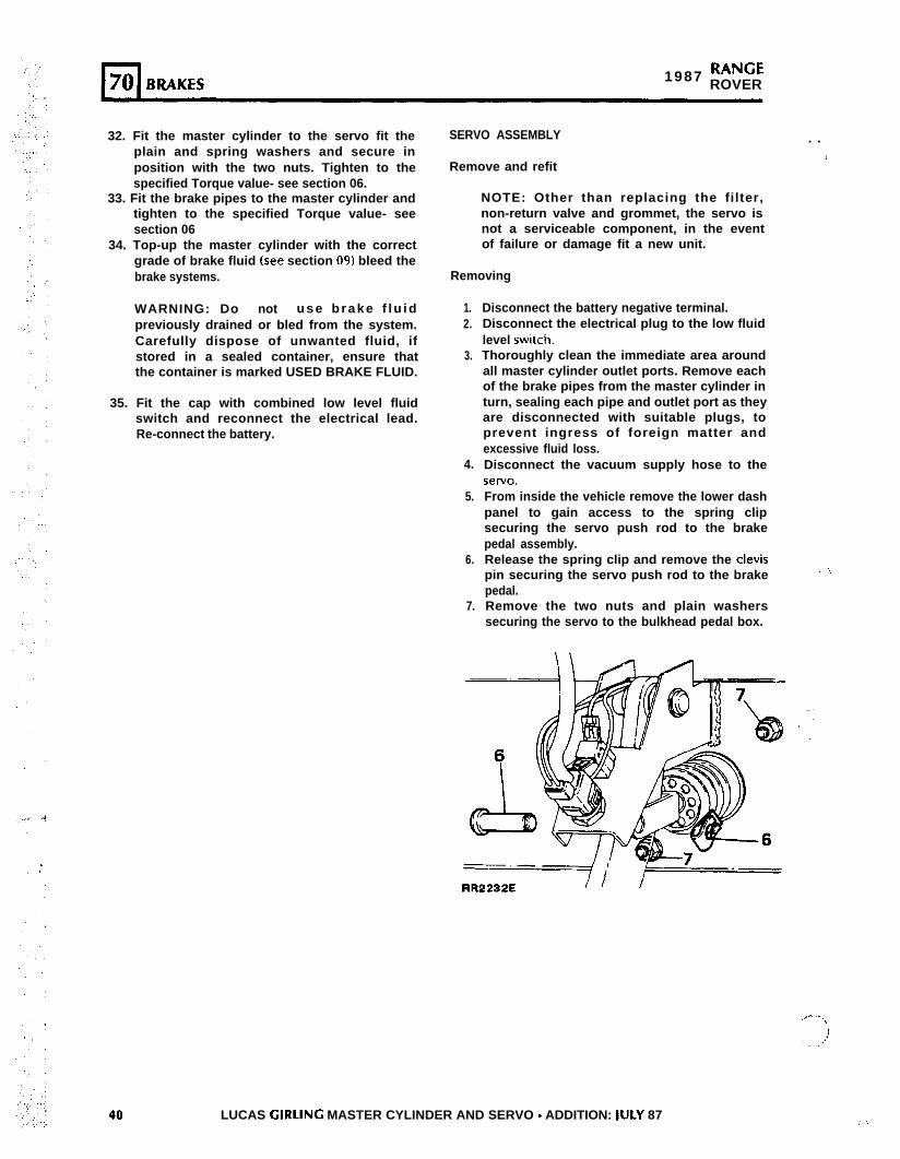
7.
Disconnect the battery negative terminal.Disconnect the electrical plug to the low fluidlevel swatch.Thoroughly clean the immediate area aroundall master cylinder outlet ports. Remove eachof the brake pipes from the master cylinder inturn, sealing each pipe and outlet port as theyare disconnected with suitable plugs, toprevent ingress of foreign matter andexcessive fluid loss.Disconnect the vacuum supply hose to theseTv0.
From inside the vehicle remove the lower dashpanel to gain access to the spring clipsecuring the servo push rod to the brakepedal assembly.Release the spring clip and remove the clevispin securing the servo push rod to the brakepedal.Remove the two nuts and plain washerssecuring the servo to the bulkhead pedal box.
. I,
40 LUCAS GIRLINC MASTER CYLINDER AND SERVO - ADDITION: IULY 87
RR2232E II I
:
:
,
::.‘( ,.; ; :
8. From within the engine compartment withdrawthe servo and master cylinder assembly.
9. Remove the cap from the reservoir and drainthe brake fluid into a suitable container. If themaster cylinder assembly can be kepthorizontal it will not be necessary to drain thefluid.
WARNING: Do not use brake fluid previouslyd r a i n e d o r b l e d f r o m t h e s y s t e m . C a r e f u l l ydispose of unwanted fluid, if stored in a sealedcontainer, ensure that the container is markedUSED BRAKE FLUID.
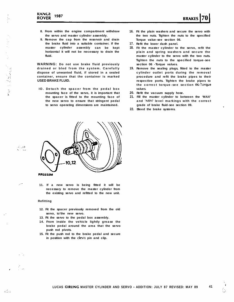
IO. Detach the spacer f rom the pedal boxmounting face of the servo, it is important thatthe spacer is fitted to the mounting face ofthe new servo to ensure that stringent pedalto servo operating dimensions are maintained.
-RR2233M
,..-- 11. If a new servo is being fitted it will benecessary to remove the master cylinder fromthe existing servo and refitted to the new unit.
Refitting
12. Fit the spacer previously removed from the oldservo, to’the new servo.
13. Fit the servo to the pedal box assembly.14. From inside the vehicle lightly grease the
brake pedal around the area that the servopush rod pivots.
15. Fit the push rod to the brake pedal and securein position with the clevis pin and clip.
, ‘,,
.,‘.
16.
17.18.
19.
20.21.
22.
Fit the plain washers and secure the servo withthe two nuts. Tighten the nuts to the specifiedTorque value-see section 06.Refit the lower dash panel.Fit the master cylinder to the servo, refit theplain and spring washers and secure themaster cylinder to the servo with the two nuts.Tighten the nuts to the specified torque-seesection 06 -Torque values.Remove the sealing plugs, fitted to the mastercylinder outlet ports during the removalprocedure and refit the brake pipes to theirrespective ports. Tighten the brake pipes tothe cor rect to rque-see sect ion 06-Torquevalues.Refit the vacuum supply hose.Fill the master cylinder to between the ‘MAX’and ‘MINI level markings with the correctgrade of brake fluid-see section 09.Bleed the brake systems.
7
‘.
LUCAS GIRLINC MASTER CYLINDER AND SERVO - ADDITION: JULY 87 REVISED: MAY 89 41 i:’ ‘.,..:.,:.
RANGE“*’ ROVER
PEDAL ASSEMBLY Refitting
Remove, overhaul and refit
Remove
10.11.
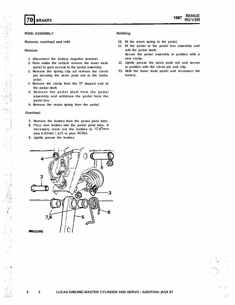
1. Disconnect the battery negative terminal.2. From inside the vehicle remove the lower dash
panel to gain access to the pedal assembly.3. Release the spring clip ad remove the clevis
pin securing the servo push rod to the brakepedal.
12.
13.
4. Remove the circlip from the ‘D’ shaped end ofthe pedal shaft.
5 . Remove the pedal shaf t f rom the pedalassembly and withdraw the pedal from thepedal box.
6. Remove the return spring from the pedal.
Overhaul
7.8.
9.
Remove the bushes from the pedal pivot tube.Press new bushes into the pedal pivot tube. Ifnecessary ream out the bushes to 15.87mmplus O.OSmm t.625 in plus .002in).Lightly grease the bushes.
RR2220E I ICI
Fit the return spring to the pedal.Fit the pedal to the pedal box assembly andrefit the pedal shaft.Secure the pedal assembly in position with anew circlip.Lightly grease the servo push rod and securein position with the clevis pin and clip.Refit the lower dash panel and reconnect thebattery.
4 2 LUCAS CIRLING MASTER CYLINDER AND SERVO - ADDITION: ]ULY 87
,’
PARKING BRAKE CABLE
Remove and refit
Removing
Inside the vehicle
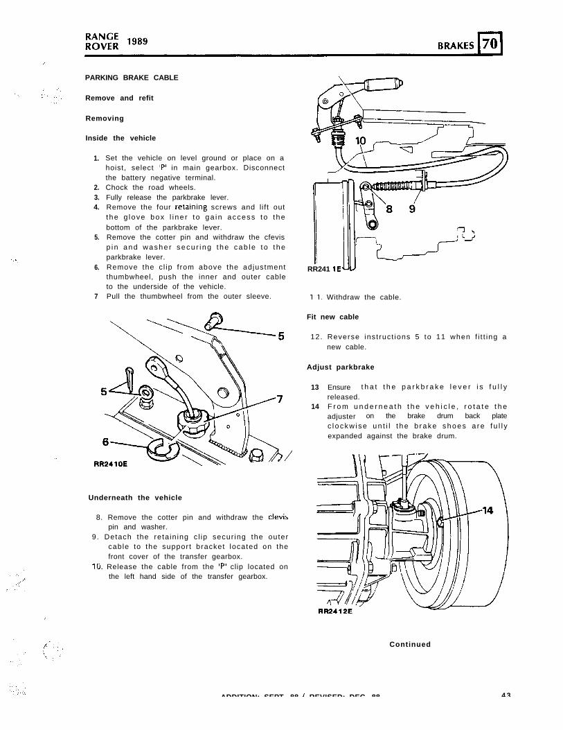
1.
2.3.4.
5.
6.
7
Set the vehicle on level ground or place on ahoist, select ‘P’ in main gearbox. Disconnectthe battery negative terminal.Chock the road wheels.Fully release the parkbrake lever.Remove the four retainrng screws and l i ft outt he g love box l i ne r t o ga in access t o t hebottom of the parkbrake lever.Remove the cotter pin and withdraw the cfevisp i n and washe r secu r i ng t he cab le t o t heparkbrake lever.Remove the c l ip f rom above the adjustmentthumbwheel, push the inner and outer cableto the underside of the vehicle.Pull the thumbwheel from the outer sleeve.
‘..
Underneath the vehicle
8. Remove the cotter pin and withdraw the clevispin and washer.
9. Detach the reta in ing c l ip secur ing the outercable to the support bracket located on thefront cover of the transfer gearbox.
10. Release the cable from the ‘P’ clip located onthe left hand side of the transfer gearbox.
RR241 1Ew
I I, Withdraw the cable.
Fit new cable
12. Reverse inst ruct ions 5 to 11 when f i t t ing anew cable.
Adjust parkbrake
13
14
Ensure t h a t t h e p a r k b r a k e l e v e r i s f u l l yreleased.F r o m u n d e r n e a t h t h e v e h i c l e , r o t a t e t h eadjuster on the brake drum back platec l ockw i se un t i l t he b rake shoes a re f u l l yexpanded against the brake drum.
I
Continued
ADDITION: SEPT. 88 / REVISED: DEC. 88 4 3
:.
:.
., ,’
‘. .:
,’
l-l RANGE70 BRAKES “*’ ROVER
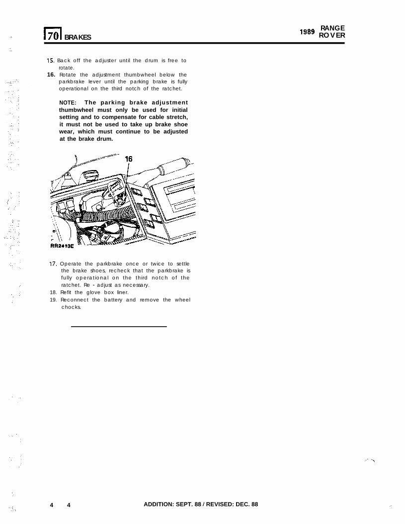
15. Back off the adjuster until the drum is free torotate.
16. Rotate the adjustment thumbwheel below theparkbrake lever until the parking brake is fullyoperational on the third notch of the ratchet.
NOTE: The parking brake adjustmentthumbwheel must only be used for initialsetting and to compensate for cable stretch,it must not be used to take up brake shoewear, which must continue to be adjustedat the brake drum.
17. Operate the parkbrake once or twice to settlethe brake shoes, recheck that the parkbrake isfully operational on the third notch of theratchet. Re - adjust as necessary.
18. Refit the glove box liner.19. Reconnect the battery and remove the wheel
chocks.
.,.
:; 4 4_:.
ADDITION: SEPT. 88 / REVISED: DEC. 88 ::
.I,.
..
:
‘.
.a
., ,.
:
.:
‘. .’
.:.
: :‘:. 1.:
.’.‘.’
‘,. ::.:.::
CLQMON DEWANDRE - WABCO POWERASSISTED HYDRAULIC BRAKE SYSTEM WITHINTEGRATED ANTI-LOCK BRAKE SYSTEM - ABS
1NTRODVCTlON
The purpose of ABS is to prevent the vehiclewheels locking during brake application, thusmaintaining vehicle steerability and stability. Thisallows the vehicle to be steered whilst the brakesare applied, even under emergency conditions, andto avoid obstacles where there is sufficient space toredirect the vehicle.
WARNING: ABS IS AN AID TO RETAININGSTEERING CONTROL AND STABILITY WHILEBRAKING.
- ABS CANNOT DEFY THE NATURAL LAWS OF DO NOT flush the brake system with any fluidPHYSICS ACTING ON THE VEHICLE. other than the recommended brake fluid.
- ABS WILL NOT PREVENT ACCIDENTSRESULTING FROM EXCESSIVE CORNERINGSPEEDS, FOLLOWING ANOTHER VEHICLE TOOCLOSELY OR AQUAPLANING, I.E. WHERE ALAYER OF WATER PREVENTS ADEQUATECONTACT BETWEEN THE TYRE AND ROADSURFACE.
The brake system must be drained and flushedat the recommended service intervals.
Fluid pressures of 170 bar (2466 psi) areproduced by the hydraulic pump. It is essentialthat the procedure for depressurising the systemis carried out where instructed.
- THE ADDITIONAL CONTROL PROVIDED BY ABSMUST NEVER BE EXPLOITED IN A DANGEROUSOR RECKLESS MANNER WHICH COULDJEOPARDISE THE SAFETY OF THE DRIVER OROTHER ROAD USERS.
COMPONENT DESCRIPTION
- Numbers refer to RR2705
Hydraulic booster unit (1)
SYSTEM DESCRIPTION
.”
The brake system is hydraulically power assistedwith an integrated, electronically controlled fourchannel anti-lock brake system (ABS).The use of a power assisted brake system means‘that during brake application, additional hydraulicenergy is provided by a hydraulic power unit.This hydraulic power unit consists of an electricallydriven pump and an accumulator which storeshydraulic energy in readiness for brake application.A pressure switch controls the hydraulic pump tomaintain fluid pressure in the accumulator.
The hydraulic system comprises two completelyindependent circuits. The rear calipers and upperp is tons o f the f ront ca l ipers fo rm the POWERCIRCUIT The lower pistons in the front calipersform the COMBINED POWER/HYDROSTATIC
T”, CIRCUIT ,
‘. :
CAUTION: THOROUGHLY CLEAN ALL BRAKECOMPONENTS, CALIPERS, PIPES AND FllTlNGSBEFORE COMMENCING WORK ON THE BRAKESYSTEM. FAILURE TO DO SO COULD CAUSEF O R E I G N M A T T E R T O E N T E R T H E S Y S T E M A N DDAMAGE SEALS AND PISTONS, WHICH WILLSERIOUSLY IMPAIR BRAKE SYSTEM EFFICIENCY.
WARNING:
DO NOT use brake fluid previously bled fromthe system.
DO NOT use old or stored brake fluid.
ENSURE that only new fluid is used and that it istaken from a clean sealed container.
Mounted in the same position as the conventionalmaster cylinder/servo unit, the booster unit containsthe following components: Fluid reservoir, powervalve, master cylinder, isolating valve, ABS solenoidcontrol valves, semo cylinder.
NOTE: The hydraulic booster unit is not aserviceable item, if internal failure occurs a newunit must be fitted. The fluid reservoir and itsseals may be changed in the event of damage.Extreme care must be taken when changing sealsto avoid ingress of debris.
Fluid reservoir (1 .l).:
Mounted on top of the booster unit, the plasticreservoir is subdivided internally to provide separatecapacity for the brake fluid used in the hydrostaticand power circuits. A central tube incorporates afilter and a low fluid warning level switch.
ADDITION: SEPT. 89 45
‘I
,:
.:
;
‘.
. .
: :
‘.
.’
‘:
:.
,‘,‘,
.’1, (1
::.
:: .,:
.;
._ 1.
.::
.+
.:.
:.:..I’,..,.
::.:.
‘.A‘.::,: . . . . ,:.‘:_.,. . . . ,.*.
KANGtilggo R O V E R
,
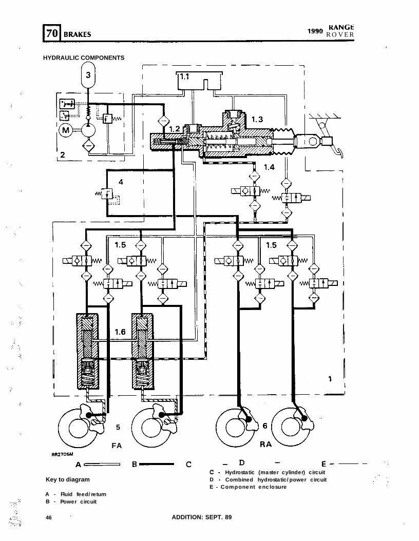
HYDRAULIC COMPONENTS
n I--- -----7
I
I
5
FA
Am B-
Key to diagram
A - Fluid feed/returnB - Power circuit
C - D - E---c - Hydrostatic (master cylinder) circuitD - Combined hydrostatic/power circuitE - Component enclosure
46 ’ ADDITION: SEPT. 89‘.
!’Power valve (1.2)
: The power valve is an extension of the mastercylinder, it controls fluid pressure in the powercircuit in direct proportion to pressure in the mastercylinder. The power valve is of spool valve design.
Master cylinder (1.3)
Operation of the master cylinder displaces a volumeof brake fluid into the servo cylinders and increasesfluid pressure. Piston movement inside the mastercylinder will also activate the power valve. A tiltvalve is incorporated to supply fluid to the mastercylinder from the reservoir connection.
tsolating valve (1.4)
:
The isolating valve consists of two solenoid valvescontrolling fluid inlet and outlet. Their function is todisconnect the master cylinder from the servocylinder and to connect the servo cylinder to thereservoir return during ABS function.
ABS solenoid control valves - 8 off (1.5)
Each pair, comprising inlet and outlet solenoidvalves, controls ABS braking to each wheel. Inresponse to signals from the ECU, the valvesdecrease, hold or increase brake pressure accordingto the need to retain wheel rotation and obtainoptimum braking. The solenoid valves are designedto respond rapidly to ECU signals.
Servo cylinders - 2 off (1.6)
The servo cylinders have four functions.
,” 1. To provide combined energy from both thehydrostatic and the power circuit to the brakecalipers.
2. To provide ‘brake feel’ at the brake pedal.3. To provide hydrostatic (master cylinder)
braking through the servo cylinder to thecalipers in the event of no power circuitpressure to the servo cylinder.
4 . To prov ide brak ing f rom both the powercircuit and from hydrostatic fluid remaining inthe servo cylinder, in the event of nohydrostatic circuit pressure from the mastercylinder.
Hydraulic power unit (2)
The hydraulic power unit comprises an electricallydriven pump and a pressure switch. The pressureswitch incorporates three electro-mechanicalswitches: one for the pump, another, at a differentpresure setting, to illuminate the pressure warninglight, The latter switch plus the third switch informthe ECU of low pressure and that ABS functionshould cease whilst pressure remains low.The pump also incorporates a non-return valve, alow pressure inlet filter, and a pressure relief valveto protect the system.
Accumulator (3)
The diaphragm accumulator is precharged withnitrogen, its function IS to store hydraulic energy.
Pressure conscious reducing valve (PCRV) (4)
The PCRV valve is located between the power valveand the ABS solenoid valves for the rear axle. Itsfunction is to limit the brake pressure to the rearaxle.
Brake calipers - front - (5) rear - (6)
NOTE: To identify the separate hydraulic circuits,they are referred to as Hydrostatic and Powercircuits.
Power circuit - The rear calipers and the upperpistons in the front calipers form one circuit,supplied by direct hydraulic power from the powervalve.
Hydrostatic circuit - The lower pistons in the frontcalipers form the other circuit, supplied withh y d r a u l i c e n e r g y f r o m t h e s e r v o c y l i n d e r scomprising a combination of master cylinderpressure and direct hydraulic power.
I‘.‘...‘, ..*:’
ADDITION: SEPT. 89 / REVISED: MARCH 90 47
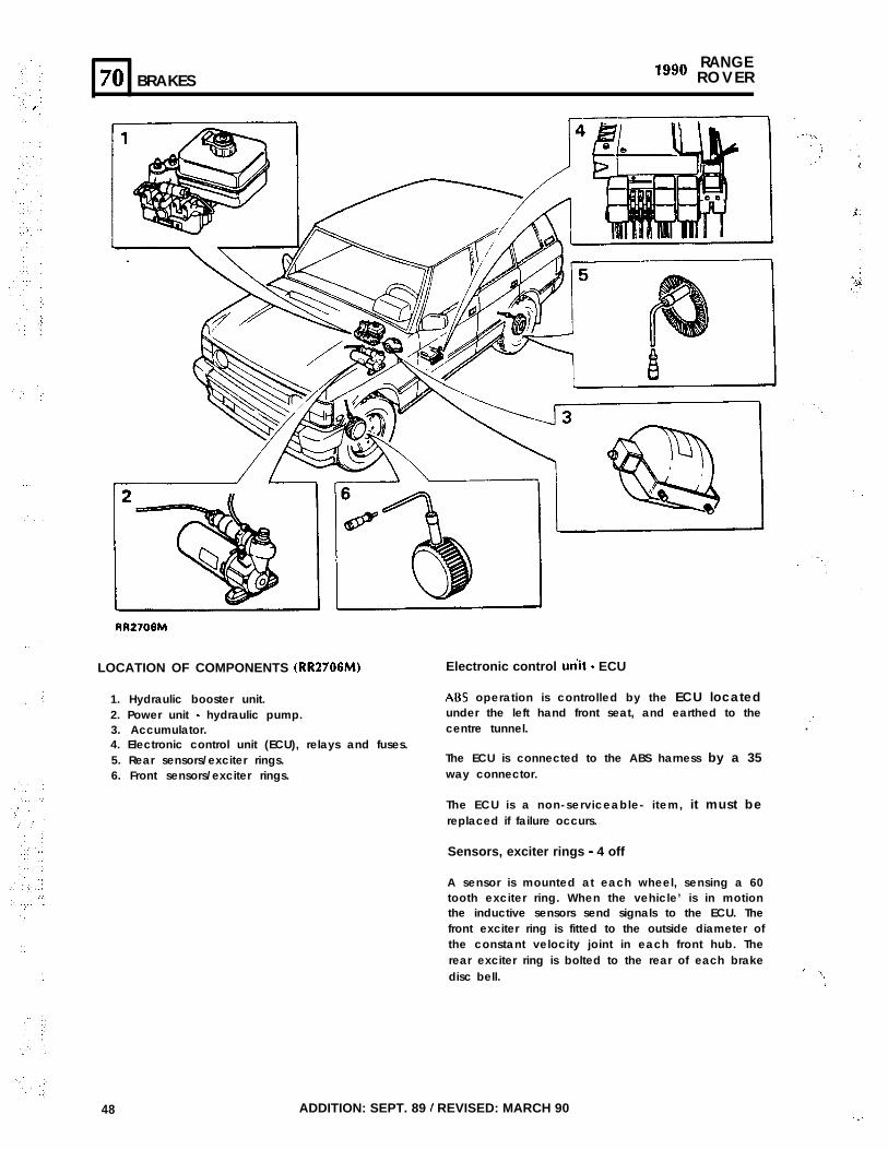
:..
‘:
‘.
‘:
RANGE70 BRAKES “‘O ROVER
RR2708M
LOCATION OF COMPONENTS (RR2706M)
1. Hydraulic booster unit.2. Power unit - hydraulic pump.3. Accumulator.4. Electronic control unit (ECU), relays and fuses.5. Rear sensors/exciter rings.6. Front sensors/exciter rings.
Electronic control unit - ECU
ABS operation is controlled by the ECU locatedunder the left hand front seat, and earthed to thecentre tunnel.
The ECU is connected to the ABS harness by a 35way connector.
The ECU is a non-serviceable- item, it must bereplaced if failure occurs.
.’.
Sensors, exciter rings - 4 off
A sensor is mounted at each wheel, sensing a 60tooth exciter ring. When the vehicle’ is in motionthe inductive sensors send signals to the ECU. Thefront exciter ring is fitted to the outside diameter ofthe constant velocity joint in each front hub. Therear exciter ring is bolted to the rear of each brakedisc bell.
I. ‘..,/
48 ADDITION: SEPT. 89 / REVISED: MARCH 90 . . :
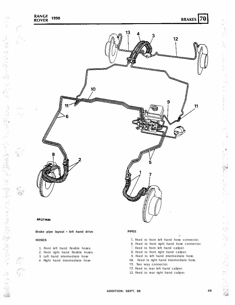
RR2714M
Brake pipe layout - left hand drive
HOSES
1. Front left hand flexible hoses.2. Front right hand flexible hoses.3. Left hand intermediate hose4. Right hand intermediate hose
PIPES.i
5. Feed to front left hand hose connector.6. Feed to front right hand hose connector.7. Feed to front left hand caliper.8. Feed to front right hand caliper.9. Feed to left hand intermediate hose.
10. Feed to right hand intermediate hose.11. Two way connector.12. Feed to rear left hand caliper.13. Feed to rear right hand caliper.
ADDITION: SEPT. 89 49
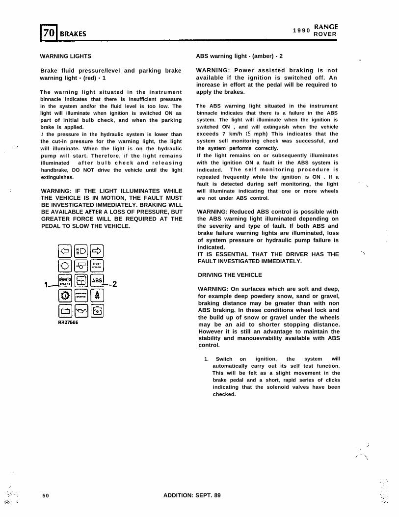
,. ..’
.’
‘,
‘.
:,‘., ,‘,. .,
,:.I. “:,
..::.:: :.
1 9 9 0 RANGEROVER
WARNING LIGHTS
Brake fluid pressure/level and parking brakewarning light - (red) - 1
The warning l ight s i tuated in the instrumentbinnacle indicates that there is insufficient pressurein the system and/or the fluid level is too low. Thelight will illuminate when ignition is switched ON aspart of initial bulb check, and when the parkingbrake is applied.If the pressure in the hydraulic system is lower thanthe cut-in pressure for the warning light, the lightwill illuminate. When the light is on the hydraulicpump will start. Therefore, if the light remainsilluminated a f t e r b u l b c h e c k a n d r e l e a s i n ghandbrake, DO NOT drive the vehicle until the lightextinguishes.
WARNING: IF THE LIGHT ILLUMINATES WHILETHE VEHICLE IS IN MOTION, THE FAULT MUSTBE INVESTIGATED IMMEDIATELY. BRAKING WILLBE AVAILABLE AFFER A LOSS OF PRESSURE, BUTGREATER FORCE WILL BE REQUIRED AT THEPEDAL TO SLOW THE VEHICLE.
50 ADDITION: SEPT. 89
ABS warning light - (amber) - 2
WARNING: Power assisted braking is notavailable if the ignition is switched off. Anincrease in effort at the pedal will be required toapply the brakes.
. .
The ABS warning light situated in the instrumentbinnacle indicates that there is a failure in the ABSsystem. The light will illuminate when the ignition isswitched ON , and will extinguish when the vehicleexceeds 7 km/h (5 mph) This indicates that thesystem sell monitoring check was successful, andthe system performs correctly.If the light remains on or subsequently illuminateswith the ignition ON a fault in the ABS system isindicated. T h e s e l f m o n i t o r i n g p r o c e d u r e i srepeated frequently while the ignition is ON . If afault is detected during self monitoring, the lightwill illuminate indicating that one or more wheelsare not under ABS control.
WARNING: Reduced ABS control is possible withthe ABS warning light illuminated depending onthe severity and type of fault. If both ABS andbrake failure warning lights are illuminated, lossof system pressure or hydraulic pump failure isindicated.IT IS ESSENTIAL THAT THE DRIVER HAS THE .‘.FAULT INVESTIGATED IMMEDIATELY.
DRIVING THE VEHICLE
WARNING: On surfaces which are soft and deep,for example deep powdery snow, sand or gravel,braking distance may be greater than with nonABS braking. In these conditions wheel lock andthe build up of snow or gravel under the wheelsmay be an aid to shorter stopping distance.However it is still an advantage to maintain thestability and manouevrability available with ABScontrol.
1. Switch on ignition, the system willautomatically carry out its self test function.This will be felt as a slight movement in thebrake pedal and a short, rapid series of clicksindicating that the solenoid valves have beenchecked.
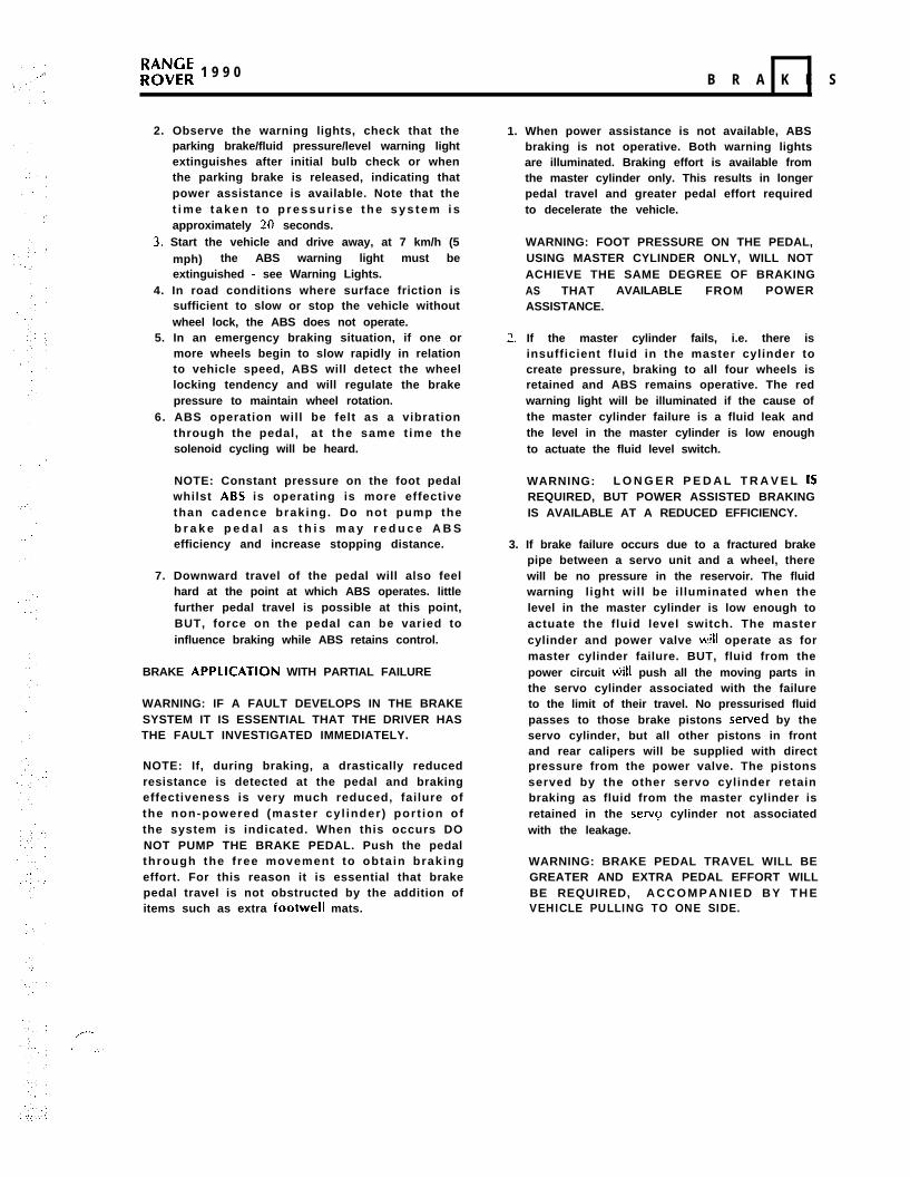
,,---
3 ‘.,
;;;;; 1 9 9 0 B R A K E S
2. Observe the warning lights, check that theparking brake/fluid pressure/level warning lightextinguishes after initial bulb check or whenthe parking brake is released, indicating thatpower assistance is available. Note that thet i m e t a k e n t o p r e s s u r i s e t h e s y s t e m i sapproximately 20 seconds.
3. Start the vehicle and drive away, at 7 km/h (5mph) the ABS warning light must beextinguished - see Warning Lights.
4. In road conditions where surface friction issufficient to slow or stop the vehicle withoutwheel lock, the ABS does not operate.
5. In an emergency braking situation, if one ormore wheels begin to slow rapidly in relationto vehicle speed, ABS will detect the wheellocking tendency and will regulate the brakepressure to maintain wheel rotation.
6. ABS operation will be felt as a vibrationthrough the pedal, at the same t ime thesolenoid cycling will be heard.
NOTE: Constant pressure on the foot pedalwhilst ABS is operating is more effectivethan cadence braking. Do not pump theb r a k e p e d a l a s t h i s m a y r e d u c e A B Sefficiency and increase stopping distance.
7. Downward travel of the pedal will also feelhard at the point at which ABS operates. littlefurther pedal travel is possible at this point,BUT, force on the pedal can be varied toinfluence braking while ABS retains control.
BRAKE APPLlCATlON WITH PARTIAL FAILURE
WARNING: IF A FAULT DEVELOPS IN THE BRAKESYSTEM IT IS ESSENTIAL THAT THE DRIVER HASTHE FAULT INVESTIGATED IMMEDIATELY.
NOTE: If, during braking, a drastically reducedresistance is detected at the pedal and brakingeffectiveness is very much reduced, failure ofthe non-powered (master cyl inder) port ion ofthe system is indicated. When this occurs DONOT PUMP THE BRAKE PEDAL. Push the pedalthrough the f ree movement to obta in brakingeffort. For this reason it is essential that brakepedal travel is not obstructed by the addition ofitems such as extra footwell mats.
1. When power assistance is not available, ABSbraking is not operative. Both warning lightsare illuminated. Braking effort is available fromthe master cylinder only. This results in longerpedal travel and greater pedal effort requiredto decelerate the vehicle.
WARNING: FOOT PRESSURE ON THE PEDAL,USING MASTER CYLINDER ONLY, WILL NOTACHIEVE THE SAME DEGREE OF BRAKINGAS THAT AVAILABLE FROM POWERASSISTANCE.
2. If the master cylinder fails, i.e. there isinsufficient fluid in the master cylinder tocreate pressure, braking to all four wheels isretained and ABS remains operative. The redwarning light will be illuminated if the cause ofthe master cylinder failure is a fluid leak andthe level in the master cylinder is low enoughto actuate the fluid level switch.
WARNING: L O N G E R P E D A L T R A V E L ISREQUIRED, BUT POWER ASSISTED BRAKINGIS AVAILABLE AT A REDUCED EFFICIENCY.
3. If brake failure occurs due to a fractured brakepipe between a servo unit and a wheel, therewill be no pressure in the reservoir. The fluidwarning light will be illuminated when thelevel in the master cylinder is low enough toactuate the fluid level switch. The mastercylinder and power valve w,ill operate as formaster cylinder failure. BUT, fluid from thepower circuit tiill push all the moving parts inthe servo cylinder associated with the failureto the limit of their travel. No pressurised fluidpasses to those brake pistons served by theservo cylinder, but all other pistons in frontand rear calipers will be supplied with directpressure from the power valve. The pistonsserved by the other servo cylinder retainbraking as fluid from the master cylinder isretained in the setvq cylinder not associatedwith the leakage.
WARNING: BRAKE PEDAL TRAVEL WILL BEGREATER AND EXTRA PEDAL EFFORT WILLBE REQUIRED, A C C O M P A N I E D B Y T H EVEHICLE PULLING TO ONE SIDE.
ADDITION: SEPT. 89 / REVISED: MARCH 90 51
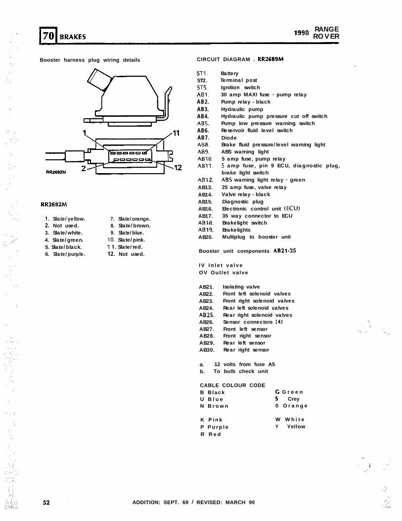
RANGElggo ROVER
Booster harness plug wiring details
1. Slate/yellow. 7. Slate/orange.2. Not used. 8. Slate/brown.3. Slate/white. 9. Slate/blue.4. Slate/green. IO. Slate/pink.5. Slate/black. I I. Slate/red.6. Slate/purple. 12. Not used.
CIRCUIT DIAGRAM . RR2669M
STI.ST2.ST5.ABl.AB2.AB3.AB4.ABS.AB6.AB7.AB8.AB9.ABlO.ABll.
ABI 2.AB13.AB14.AB15.AB16.AB17.AB18.AB19.AB20.
BatteryTerminal post
’
Ignition switch30 amp MAXI fuse - pump relayPump relay - blackHydraulic pumpHydraulic pump pressure cut off switchPump low pressure warning switchReservoir fluid level switchDiodeBrake fluid pressure/level warning lightABS warning light5 amp fuse, pump relay5 amp fuse, pin 9 ECU, diagnostic plug,brake light switchABS warning light relay - green25 amp fuse, valve relayValve relay - blackDiagnostic plugElectronic control unit (ECU)35 way connector to ECUBrakelight switchBrakelightsMultiplug to booster unit
Booster unit components ABZl-25
I V I n l e t v a l v eOV Out let va lve
AB21.AB22.AB23.AB24.AB25.AB26.AB27.AB28.AB29.AB30.
Isolating valveFront left solenoid valvesFront right solenoid valvesRear left solenoid valvesRear right solenoid valvesSensor connectors (4)Front left sensorFront right sensorRear left sensorRear right sensor
a. 12 volts from fuse A5b. To bulb check unit
CABLE COLOUR CODEB B lack G G r e e nU B l u e S CreyN B r o w n 0 O r a n g e
K P i n kP P u r p l eR R e d
W W h i t eY Yellow
ADDITION: SEPT. 69 / REVISED: MARCH 90
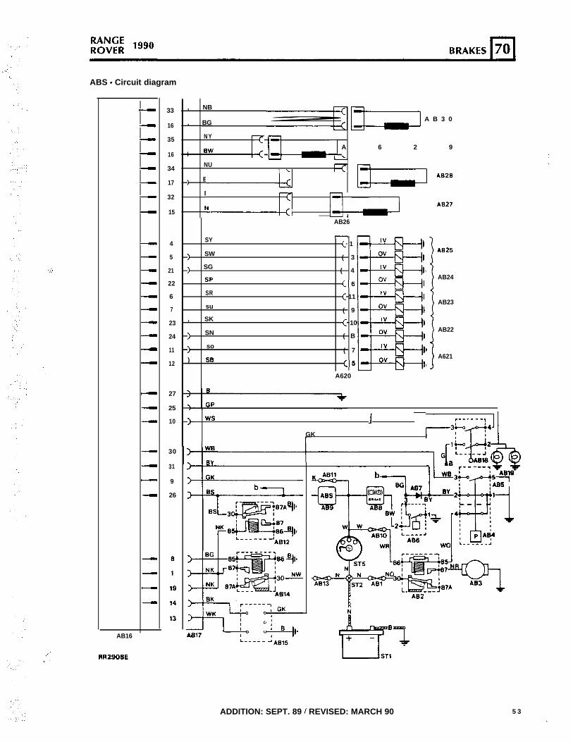
ABS - Circuit diagram
,.‘..
:,’
-
--
-
-
-
-
-
----------
-
--
-
-
-
-
-
-
AB16
,/RRZSOBE0.
33
16
35
16
34
17
32
15
4
5
21
22
6
7
23
24
11
12
27
25
10
30
31
9
26
I.
I:
, NB
, BG m A B 3 0
N Y
) BW c m A 6 2 9
NU
) BN ’ m AB26 ”
BO
-ff m A827v4
AB26
SY
) SW
) SG
SP
SR
su
, SK
> SN
) so
) SB
-( 1
( 3
( 4 ,
<6
( 11
( 9
( 10
( B
( 7 I
(5 ,
A620
1\B25
AB24
AB23
AB22
A621
) ws r------1
GK ’ ,-3p+‘lI+
t
AB2
ADDITION: SEPT. 89 / REVISED: MARCH 90 5 3(.
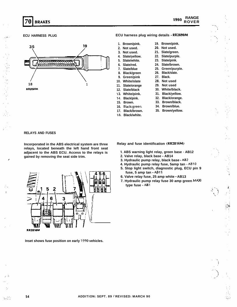
.f
:: ,.
;:
,
,. ‘,
‘.’
.,,,’ ‘,’
,..’
.: ,,
‘:.,. .;:: :: :
RANGE“‘O ROVER
ECU HARNESS PLUG
18 1RR269m4
RELAYS AND FUSES
Incorporated in the ABS electrical system are threerelays, located beneath the left hand front seatadjacent to the ABS ECU. Access to the relays isgained by removing the seat side trim.
ECU harness plug wiring details - RR2690M
1. Brown/pink.2. Not used.3. Not used.4. Slate/yellow.5. Slate/white.6. Slate/red.7. Slate/blue8. Black/green9. Green/pink
10. White/slate11. Slate/orange12. Slate/blackI 3. White/pink.14. Black/pink.15. Brown.16. Blackgreen.17. Black/brown.18. Black/white.
19. Brown/pink.20. Not used.21. Slate/green.22. Slate/purple.23. Slate/pink.24. Slate/brown.25. Green/purple.26. Black/slate.27. Black.28. Not used29. Not used30. White/black.31. Black/yellow.32. Black/orange.33. Brown/black.34. Brown/blue.35. Brown/yellow.
Relay and fuse identification (RR2816M)
1. ABS warning light relay, green base - AB122. Valve relay, black base - AB143. Hydraulic pump relay, black base - A624. Hydraulic pump relay fuse, 5amp tan - ABlO5. Stop light switch, diagnostic plug, ECU pin 9
fuse, 5 amp tan - ABll6. Valve relay fuse, 25 amp white - AB137. Hydraulic pump relay fuse 30 amp green MAXI
type fuse - ABl
RR2818M
Inset shows fuse position on early 1990 vehicles.
54 ADDITION: SEPT. 89 / REVISED: MARCH 90
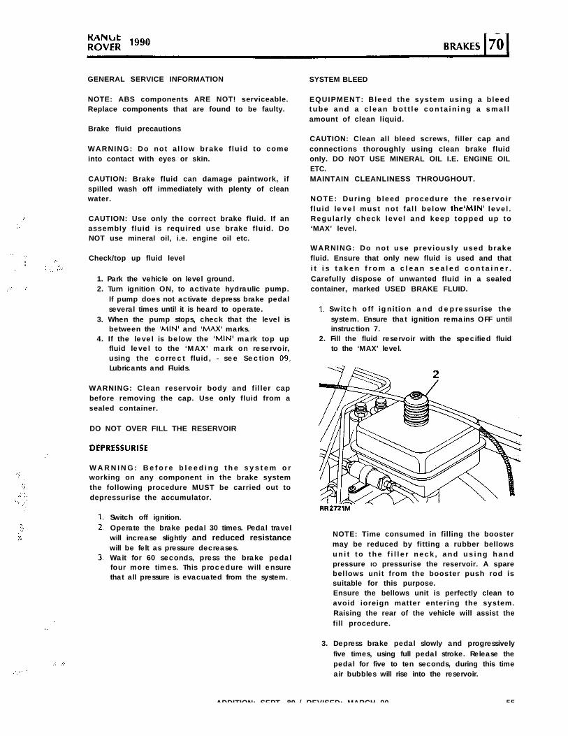
.I’:.
” .,,‘, :
,.
,:: ,’
..,I.’
.‘),..
.C I,:‘. ., ,c’.‘,
j:;;x
,.y.. :
‘,..
: .,‘, ::,:
.
‘.
.; ..:.
GENERAL SERVICE INFORMATION
NOTE: ABS components ARE NOT! serviceable.Replace components that are found to be faulty.
Brake fluid precautions
WARNING: Do not a l low brake f lu id to comeinto contact with eyes or skin.
CAUTION: Brake fluid can damage paintwork, ifspilled wash off immediately with plenty of cleanwater.
CAUTION: Use only the correct brake fluid. If anassembly fluid is required use brake fluid. DoNOT use mineral oil, i.e. engine oil etc.
Check/top up fluid level
1. Park the vehicle on level ground.2. Turn ignition ON, to activate hydraulic pump.
If pump does not activate depress brake pedalseveral times until it is heard to operate.
3. When the pump stops, check that the level isbetween the ‘MINI and ‘MAX’ marks.
4. If the level is below the ‘MINI mark top upfluid level to the ‘MAX’ mark on reservoir,using the correct f luid, - see Section 09,Lubricants and Fluids.
WARNING: Clean reservoir body and filler capbefore removing the cap. Use only fluid from asealed container.
DO NOT OVER FILL THE RESERVOIR
DEPRESSURISE
W A R N I N G : B e f o r e b l e e d i n g t h e s y s t e m o rworking on any component in the brake systemthe following procedure MUST be carried out todepressurise the accumulator.
Switch off ignition.Operate the brake pedal 30 times. Pedal travelwill increase slightly and reduced resistancewill be felt as pressure decreases.Wait for 60 seconds, press the brake pedalfour more times. This procedure will ensurethat all pressure is evacuated from the system.
SYSTEM BLEED
EQUIPMENT: Bleed the system using a bleedt u b e a n d a c l e a n b o t t l e c o n t a i n i n g a s m a l lamount of clean liquid.
CAUTION: Clean all bleed screws, filler cap andconnections thoroughly using clean brake fluidonly. DO NOT USE MINERAL OIL I.E. ENGINE OILETC.MAINTAIN CLEANLINESS THROUGHOUT.
NOTE: Dur ing bleed procedure the reservoirf lu id level must not fa l l below the’MIN’ level .Regular ly check level and keep topped up to‘MAX’ level.
WARNING: Do not use previously used brakefluid. Ensure that only new fluid is used and thati t i s t a k e n f r o m a c l e a n s e a l e d c o n t a i n e r .Carefully dispose of unwanted fluid in a sealedcontainer, marked USED BRAKE FLUID.
I. Swi tch o f f ign i t ion and depressur i se thesystem. Ensure that ignition remains OFF untilinstruction 7.
2. Fill the fluid reservoir with the specified fluidto the ‘MAX’ level.
RR2721M
NOTE: Time consumed in filling the boostermay be reduced by fitting a rubber bellowsu n i t t o t h e f i l l e r n e c k , a n d u s i n g h a n dpressure IO pressurise the reservoir. A sparebellows unit from the booster push rod issuitable for this purpose.Ensure the bellows unit is perfectly clean toavoid ioreign matter entering the system.Raising the rear of the vehicle will assist thefill procedure.
3. Depress brake pedal slowly and progressivelyfive times, using full pedal stroke. Release thepedal for five to ten seconds, during this timeair bubbles will rise into the reservoir.
ADDITION: SEPT. 89 / REVISED: MARCH 90 55
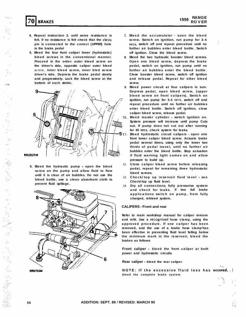
RANGElggo R O V E R
4. Repeat instruction 3. until some resistance isfelt. If no resistance is felt check that the clevispin is connected to the correct (UPPER) holein the brake pedal
7.
5. Bleed the four front caliper lower (hydrostatic)bleed screws in the conventional manner.Proceed in the order: outer bleed screw onthe driver’s side, opposite caliper outer bleedscrew, inner bleed screw, inner bled screwdriver’s side. Depress the brake pedal slowlyand progressively. Lock the bleed screw at thebottom of each stroke.
8.
9.
6. Bleed the hydraulic pump - open the bleedscrew on the pump and allow fluid to flowuntil it is clear of air bubbles. Do not use thebleed bottle, use a clean absorbant cloth toprevent fluid spillage.
RR2722Y
56 ADDITION: SEPT. 89 / REVISED: MARCH 90
12.
13.
14.
Bleed the accumulator - ooen the bleedscrew. Switch on ignition, run pump for 3-4sets, switch off and repeat procedure until nofurther air bubbles enter bleed bottle. Switchoff ignition. Close the bleed screw.Bleed the two hydraulic booster bleed screws.Open one bleed screw, depress the brakepedal, switch on ignition, run pump until nofurther air bubbles enter the bleed bottle.Close booster bleed screw, switch off ignitionand release pedal. Repeat for other bleedscrew.
,,.
Bleed power circuit at four calipers in turn.Depress pedal, open bleed screw, (upperbleed screw on front calipers). Switch onignition, run pump for 3-4 sets, switch off andrepeat procedure until no further air bubblesenter bleed bottle. Switch off ignition, closecaliper bleed screw, release pedal.Bleed master cylinder - switch ignition on.System pressure will increase until pump Cutsout. If pump does not cut out after runningfor 45 sets, check system for leaks.Bleed hydrostatic circuit calipers - open onefront lower caliper bleed screw. Actuate brakepedal several times, using only the lower twothirds of pedal travel, unti l no further airbubbles enter the bleed bottle. Stop actuationif f luid warning l ight comes on and allowpressure to build up.Close caliper bleed screw before releasingpedal, repeat for remaining three hydrostaticbleed screws.Check/top up reservo i r f lu id level - seeCheck/top up fluid level.Dry all connections, fully pressurise systemand check for leaks. If two full brakeappl icat ions swi tch on pump, f rom fu l lycharged, rebleed system.
CALIPERS - Front and rear
Refer to main workshop manual for caliper removeand refit. Use a recognised hose clamp, using theapproved procedure. I f one caliper has beenremoved, and the use of a brake hose clamp’hasbeen effective in preventing fluid level falling belowthe minimum mark in the reservoir, bleed thebrakes as follows:
Front caliper - bleed the front caliper at bothpower and hydrostatic circuits.
Rear caliper - bleed the rear caliper.
N O T E : I f t h e e x c e s s i v e f l u i d l o s s h a s occured, ..)bleed the complete brake system.
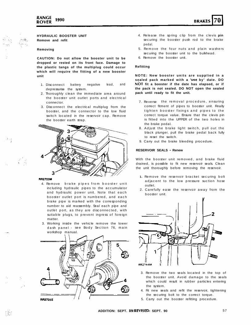
HYDRAULIC BOOSTER UNITRemove and refit
Removing
CAUTION: Do not allow the booster unit to bedropped or rested on its front face. Damage tothe plastic tangs of the multiplug could occurwhich will require the fitting of a new boosterunit
1. Disconnect battery negative lead, anddepressurise the system.
2. Thoroughly clean the immediate area aroundthe booster unit outlet ports and electricalconnector.
3. Disconnect the electrical multiplug from thebooster, and the connector to the low fluidswitch located in the reservoir cap. Removethe booster earth strap.
RR2723M
4. Remove b r a k e p i p e s f r o m b o o s t e r u n i tincluding hydraulic pipes to the accumulatorand hydraulic power unit. Note that eachbooster outlet port is numbered, and eachbrake pipe is marked with the correspondingnumber to aid reassembly. Seal each pipe andoutlet port, as they are disconnected, withsuitable plugs, to prevent ingress of foreignmatter.
3. Working inside the vehicle remove the lowerdash panel - see Body Section 76, mainworkshop manual.
RR2725E I I I
4. Release the spring clip from the clevis pinsecuring the booster push rod to the brakepedal.
5. Remove the four nuts and plain washerssecuring the booster unit to the bulkhead.
6. Remove the booster unit.
Refitting
N O T E : N e w b o o s t e r u n i t s a r e s u p p l i e d i n asealed pack marked with a ‘use by’ date. DONbT fit a booster if the date has elapsed, or ifthe pack is not sealed. DO NOT open the sealedpack until ready to fit the unit.
7. Reverse the removal procedure, ensuringcorrect fitment of pipes to booster unit. Finallyt ighten booster f i x ings and p ipes to thecorrect torque value. Ensure that the clevis pinis fitted into the UPPER of the two holes inthe brake pedal.
8. Adjust the brake l ight switch, pull out theblack plunger, pull the brake pedal back fullyto reset the switch.
9. Carry out the brake bleeding procedure.
RESERVOIR SEALS - Renew
With the booster unit removed, and brake fluiddrained, is possible to fit new reservoir seals. Cleanthe unit thoroughly before removing the reservoir.
1. Remove the reservoir bracket securing boltadjacent to the low pressure suction hoseoutlet.
2. Carefully ease the reservoir away from thebooster unit.
RR2744M lil 4 /
3. Remove the two seals located in the top ofthe booster unit. Avoid damage to the sealswhich could result in rubber particles enteringthe system.
4. Fit new seals and refit the reservoir, tighteningthe securing bolt to the correct torque.
5. Carry out the booster refitting procedure.
ADDITION: SEPT. WREVISED: SEPT. 90 57
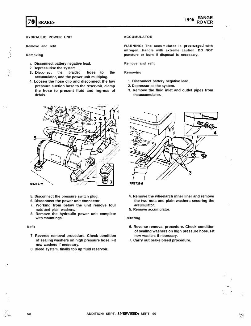
_.
.:
.)
. .
. . .
,
..:.
‘. .’;:::.
.;’ :..:..-
RANGE“‘O ROVER
. ‘..
HYDRAULIC POWER UNIT
Remove and refit
Removing
1. Disconnect battery negative lead.2. Depressurise the system.3. Disconect the braided hose to the
accumulator, and the power unit multiplug.4. Loosen the hose clip and disconnect the low
pressure suction hose to the reservoir, clampthe hose to present fluid and ingress ofdebris.
5. Disconnect the pressure switch plug.6. Disconnect the power unit connector.7. Working from below the unit remove four
nuts and plain washers.8. Remove the hydraulic power unit complete
with mountings.
Refit
7. Reverse removal procedure. Check conditionof sealing washers on high pressure hose. Fitnew washers if necessary.
8. Bleed system, finally top up fluid reservoir.
ACCUMULATOR -
WARNING: The accumulator is precharged withnitrogen. Handle with extreme caution. DO NOTpuncture or burn if disposal is necessary.
Remove and refit
Removing
1. Disconnect battery negative lead.2. Depressurise the system.3. Remove the fluid inlet and outlet pipes from
the accumulator.
.
RR2720M
4. Remove the wheelarch inner liner and removethe two nuts and plain washers securing theaccumulator. .I
5. Remove accumulator.
Refitting
6. Reverse removal procedure. Check conditionof sealing washers on high pressure hose. Fitnew washers if necessary.
7. Carry out brake bleed procedure.
58 ADDITION: SEPT. gS/REVISED: SEPT. 90
..-“.
I :
. . . .,
1,. i(. . .
1