Embed Size (px)
Citation preview
Kalu Ganga Water Project
Kalu Ganga drinking water project includes new water treatment plant and pump station located river bank of Kalu Ganga near Horana. It supplies drinking water for Bandaragama, Panadura, Moratuwa and Colombo south areas, serving more than 240,000 population.
Project consist of two phases where phase I is completed which has a capacity of 60,000 m3/day. Under phase II, this is expected to increase up to 120,000 m3/day and several civil constructions have been already completed. Total project cost is Rs. 13,929 millions and constructed treatment plant costs around 5,013 millions. This is fully automated plant and construction was started in March 2000 and completed in 2007 January. Main contractor of the project was “ChinaGeo” and electrical subcontractor ABB has provided electrical, instrumentation and control systems including SCADA system. Project includes water intakes, Treatment plant, Pump house, raw water and clean water pumping, reservoir, transmission mains and distribution systems.
During the field visit, we were familiarized with main water treatment procedure of the plant. In addition, we had chance to observe other electrical systems, plant monitoring and controlling and various machines as well as equipments involve in the process. In the case of water treatment procedure, main stages are as follows.
Raw water Intake
Water intake has a total capacity of 120,000 m3 including phase II, where 100% civil construction has completed for the total project. Intake situated at a height of 2.370m above MSL. In water intake process, screening is performed in two levels. After initial screening, fine screening is carried out to trap even small particles present.
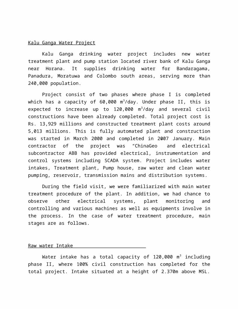
Then water is pumped to distribution chamber from there, to gain required head and gravity flow throughout the plant. Two centrifugal pumps are used, one for operation and other one remains for standby operation. Each has a flow about 730 Ltrs/s which is driven by 200 kW/ 400 V motor. These motors are controlled by Variable Speed Drives (VSD s) and each motor fed by separate individual power supplies which has enhanced the reliability of units. VSD s regulate pump flow rate according to variations of intake water level. As other sections, this facilitates full automated mode of operation through central SCADA system. In addition, controlling could be done onsite
via touch panels (Auto/manual mode) and control panel switches. Priority level arranged in reverse order i.e switch panels, touch panels and finally SCADA system accordingly. Therefore, this can be operated independently and it further ensures safety of the operators and maintenance staff.
Distribution Chamber
Water pumped from raw water intake is collected and distributed from here maintaining required gravity flow throughout the plant. Before entering in to main process, raw water quality and other flow measurements are taken. Basically chemical treatment procedure takes place hereafter.
Alum Treatment: Alum is added to neutralize negative charged particles (mud) present in the water. When these charges get attached with Al irons, particle size will increase and could be separated in latter stage.
Lime treatment: In order to optimize above alum treatment pH value should be maintained in desired levels. Lime is used to increase pH value once required especially when river water level increases causing reduction of pH value. In addition, pre chorine treatment can be performed to remove excess iron content and algae. But those operations are optional and not frequently take place.
In this stage rapid mixing is expected supported by hydrostatic mixers and positive displacement pumps. Operator can input required dosage to system and then considering other parameters mixing operation is performed by VSD controlled mixers.
Flocculation and Sedimentation Stage
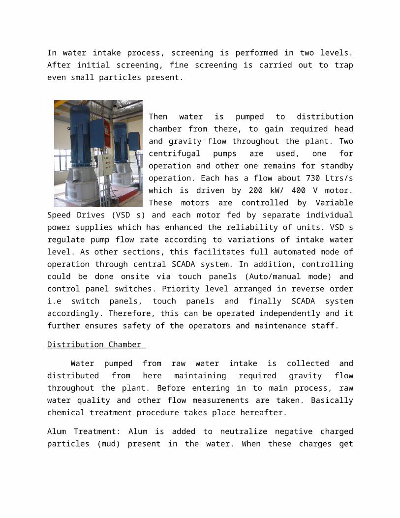
In this stage chemical treated water then circulated through array of tanks. As a result of chemical treatments, light colloidal parts stick together and float above while heavy particles precipitate at the bottom. In initial flocculation tanks, low velocity gradient is maintained and particle flocks are created. Then in sedimentation tanks, sediments are created and precipitate in the bottom. Here water flow is maintained even lower and smooth level. Each tank has
rotating drum with sludge scrapers to remove those sediments out of the tanks. This sludge collected to pockets and removed to sludge lagoon through gravity flow.
Filtering Stage
After sedimentation tanks, water flows to filtering stage. There are four filter units in operation. In filtering tanks, water enters from the top of tanks then flow through the sand layer and finally leaves through the nozzles at the bottom. About 1.2m thick sand layer is used and opening of a nozzle is smaller than average size of sand particles (<1mm). Then, this filtered water is treated with right doasge of chlorine to destroy remaining pathogens. Generally, at consumer end, residual chlorine amount of the water is about 0.2 mg/ltr. But in the treatment plant 0.8-1 mg/ltr amount is added, due to intermediate precipitation and reduction in tanks and distribution lines. Additionally, lime also added in small proportions to control the pH value.
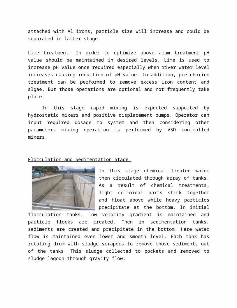
Backwashing process
This is a special process used to clean the filtering medium use for filtering process. This is carried out in routine basis without interrupting usual operations and when one unit is under backwashing operation other units can operate as usual. We were able to observe this operation in filtering unit 4. In this case, simply reverse flow is used to clean filtering sand layer. Firstly, inflow gates are closed and wait until water level is reduced below inner walls. Then back washing gate is opened. Thereafter, compressed air is injected through bottom nozzles for several minutes. This is followed by air and water flow (9 min.) and lastly by water (7.5 min). During this process, water flowing through the gate get collected in backwash recovery tank and fed back to the system again.
At final stage, purified water is pumped to Allakanda reservoir which is situated 4.2 km away. It has a capacity of 15,000 m3. In order to pump water to this high level reservoir, three high lift pumps are used, whereas one unit kept for standby operation. Those soft starter motors have rated capacity of 500 kW.
Electrical Substation
Plant has separate electrical substation which is fed by 33kV power supply and 2000kVA Power transformer is used. Other equipments include HV/LV switchgears, protection relays, UPS system (10 kVA) and standby diesel generator units. In addition to main generator (1500 kVA), auxiliary generator unit (60kW) is used for plant lighting and other auxiliary consumption. Like most of other designs, substation has been designed to accommodate phase II also, where bus coupler can be used for further extensions. In case of power cut, reservoir capacity able to tolerate about one hour period, but not more than that, therefore plant should have to be operated through backup generators. In addition, plant is frequently exposed to lighting conditions which affects especially various kinds of sensors, protection systems etc.
Lightning protection is provided for all structures and all equipments and structures are connected to common earthing grid.
Water Quality measurement
Water quality is monitored continuously in several stages. Raw water, unsettled water, settled water, filtered water and final water quality and other parameters (like pH value, stability) can be monitored via analyzer rack in the laboratory. Those records can be monitored through SCADA system also. In addition, manual sampling tests are done at least for 3 hours in the laboratory. Moreover, since it is responsibility of the facility to maintain water quality in tanks and reservoirs, water quality is measured in overhead tanks weekly.
Overall System Monitoring
Each and every component of the plant is connected by central SCADA system. This enables fully automated remote operation and controlling of entire facility with real time monitoring.
As a summary, during this field visit, we were able to familiarize with state of art of the water treatment facility and its operational and technical aspects. Furthermore, it was valuable opportunity for all of us to closely observe the entire procedure in such a detailed manner. Finally, I would like to thank all the staff of the facility for their time and efforts and all other individuals who made this a success.