Embed Size (px)
Citation preview

754 IEEE TRANSACTIONS ON ROBOTICS, VOL. 32, NO. 3, JUNE 2016
Continuum Differential Mechanisms and Their Applicationsin Gripper Designs
Kai Xu and Huan Liu
Abstract—Differential mechanisms possess various forms and are ap-plied in a wide spectrum of mechanical systems. This paper proposes tocategorize differential mechanisms into kinematic differential mechanisms(KDMs) and continuum differential mechanisms (CDMs), and also intro-duces two CDMs. The working principle, structures, constructions, andkinetostatic analyses of the proposed planar and the spatial CDMs areelaborated upon. The planar CDM is compared with two widely used dif-ferential mechanisms made from pulleys and linkages to show its effec-tiveness using a simple construction. The spatial CDM could resolve oneinput into three outputs in a way different from two serially connectedplanar differential mechanisms. As demonstrated in experimentation, thespatial CDM could allow more isotropic distribution of the three outputs.The categorization, analyses, and applications of the CDMs might not onlyextend the IFToMM terminology on differential mechanisms, but also in-spire more CDM designs with distinct responses and properties for adaptivemechanical systems.
Index Terms—Continuum mechanism, differential mechanism, forcetransmission matrix, gripper, kinetostatics.
I. INTRODUCTION
According to the IFToMM terminology, a differential mech-anism may resolve a single input into two outputs dependingon the external constraints and loads [1]. Various differentialmechanisms could be found in a wide spectrum of mechanicalsystems since the presence of a differential mechanism intro-duces a level of adaptivity and operation flexibility. For exam-ple, the differential mechanism in an automobile transmissionallows the redistribution of the outputs, whereas the differentialmechanisms in industrial grippers and robotic hands help formadaptive grasps.
Differential mechanisms usually possess several typical struc-tures, including the following [2]:1) pulley-based forms;2) linkage-based forms;3) gear-based forms;4) fluidic T-pipe-based forms.
Since differential mechanisms are widely used, this studylimits the literature review to their uses in gripping de-
Manuscript received December 23, 2015; revised April 11, 2016; acceptedApril 26, 2016. Date of publication May 20, 2016; date of current version June3, 2016. This paper was recommended for publication by Associate Editor V.Krovi and Editor I.-M. Chen upon evaluation of the reviewers’ comments. Thiswork was supported by the National Program on Key Basic Research Projectsunder Grant 2011CB013300, in part by the Shanghai Rising-Star Program underGrant 14QA1402100, and in part by the National Natural Science Foundationof China under Grant 51435010 and Grant 51375295.
K. Xu is with the Laboratory of Robotics Innovation and Intervention, UM–SJTU Joint Institute, and with State Key Laboratory of Mechanical System andVibration, Shanghai Jiao Tong University, Shanghai 200240, China (e-mail:[email protected]).
H. Liu is with the Laboratory of Robotics Innovation and Intervention, UM–SJTU Joint Institute, Shanghai Jiao Tong University, Shanghai 200240, China(e-mail: [email protected]).
Color versions of one or more of the figures in this paper are available onlineat http://ieeexplore.ieee.org.
Digital Object Identifier 10.1109/TRO.2016.2561295
vices, such as robotic hands, industrial grippers, and prosthetichands.
While used in multijoint industrial grippers or robotic hands,differential mechanisms reduce the number of actuators, reducethe control complexity, and form compliant and adaptive grasps.Then, various objects could be conveniently grasped by grippersand hands with a few actuators.
Moveable pulleys might be the most widely used design op-tion to construct differential mechanisms. Using stacked move-able pulleys, multijoint prosthetic hands with one actuator wererealized [3]–[5]. Linkage-based seesaw differential mechanismsare also used to achieve similar design goals, leading to designsof one-actuator humanoid robotic hands [6], [7]. What’s more,differential mechanisms using planetary gears and fluidic T-shape pipes were also used, to design industrial grippers suchas the SARAH-M1 hand [8] and the LIRMM hand [9].
It is possible to use differential mechanisms in a reversedway. Namely, two inputs are used to determine one output. Forexample, this approach has been applied to design prosthetichands with mechanically implemented postural synergies, inwhich multiple sets of differential mechanisms are used to formgrasping poses of a multijoint hand from two actuators. Theexamples include pulley-based designs [10]–[12] and planetary-gear-based designs [13], [14].
It is worth noting that using differential mechanisms is justone way to design underactuated grippers or hands. Other pos-sibilities include the uses of spring-biased linkage [15], biasedcable routing [16]–[19], biased gear transmission [20], and com-pliant structures [21]–[25].
Examining the mentioned differential mechanisms, one canconclude that three types could be categorized as kinematicdifferential mechanisms (KDMs):1) the pulley-based designs;2) the linkage-based designs;3) the gear-based designs.
These KDMs generate differential outputs from the motionsof the kinematic pairs. The fluidic T-pipe-based differentialmechanism is not a KDM, since it generates differential out-puts from the redistribution of its fluids.
This paper proposes to categorize differential mechanismsinto KDMs and continuum differential mechanisms (CDMs).CDMs generate differential outputs via redistributions and/ordeformations of their own materials and structures. The fluidicT-pipe-based differential mechanism could be referred to as avolume CDM, since its volume material is redistributed.
Two CDM designs are introduced: planar and spatial CDM,as shown in Fig. 1. Both CDMs generate differential outputs viadeformations of their flexible structures. The working principle,constructions, kinetostatic analyses, and design examples are
1552-3098 © 2016 IEEE. Personal use is permitted, but republication/redistribution requires IEEE permission.See http://www.ieee.org/publications standards/publications/rights/index.html for more information.

IEEE TRANSACTIONS ON ROBOTICS, VOL. 32, NO. 3, JUNE 2016 755
Fig. 1. Continuum differential mechanisms: (a) planar and (b) spatial forms.
presented. The planar CDM concept was proposed in a previousstudy [26], in which it was used to design a single-actuatorprosthetic hand. The spatial CDM concept is proposed here forthe first time.
Note that the proposed CDMs might be considered to besimilar to parallel robots with flexible legs (e.g., the one in[27]). However, the essential working principle of a CDM isentirely different from the flexible-linked parallel robots.
The contributions of this paper include: 1) the proposal of thespatial CDM and the categorization for differential mechanisms;and 2) the kinetostatic analyses, comparisons, and experimentalcharacterizations of two CDMs.
Exhibited by the designs and experimental results in [26]and later sections, major advantages of using CDMs includethe design compactness and structure simplicity, besides thefact that a spatial CDM inherently resolves one input into threeoutputs. Due to the inherent compliance, the CDMs might notbe suitable for the scenarios in which large output forces areneeded. However, the CDMs could certainly find applicationsin which small differential output forces are needed in a confinedspace.
This paper is organized as follows. Section II presents theconcept and working principle of the proposed CDMs. SectionIII presents detailed kinetostatic analyses and the comparisonsof the CDMs with two other differential mechanisms. Designparadigms and the experimental characterizations are detailedin Section IV. The conclusion is summarized in Section V.
II. CONTINUUM DIFFERENTIAL MECHANISMS
The proposed CDMs have planar and spatial forms, as shownin Fig. 1. They consist of a rigid base link, a flexible inputbackbone, a rigid end link, and two or three output backbones.The output backbones could be arranged arbitrarily around theinput backbone in the spatial CDM, while the backbones are ina plane for the planar CDM. All the backbones are attached tothe end link and can slide in holes in the base link.
The CDM can provide pushing as well as pulling outputs.As shown in Fig. 1(a) for the planar CDM, a force fa acts
on the input backbone to generate two outputs to push externalobjects. When the load on the left is bigger (indicated by thelonger arrow), continuing to drive the input backbone wouldbend all the backbones to generate differential outputs. Theobject on the right will be continuously pushed.
Similarly, in Fig. 1(b) for the spatial CDM, a force fa on theinput backbone could generate three pulling outputs (externalobjects are pulled). When the load on one backbone is bigger(indicated by the longer arrow), continuing to drive the inputbackbone would bend the spatial CDM for differential outputs.
The bent shapes of the backbones could be approximated ascircular arcs according to previous analytical and experimentalstudies [28], [29]. A few spacer links might be needed betweenthe end link and the base link for this assumption to hold, whenthe CDMs become relatively long. These backbones are notaddressed as tendons because they can be pulled and pushed. Atendon usually can only be pulled.
The proposed CDMs generate differential outputs fromthe structure deformations. A fluidic T-pipe-based differentialmechanism could be called a volume CDM to differentiate itselffrom the planar and spatial CDMs. The current IFToMM ter-minology on differential mechanisms actually only covers theKDM scenarios [1]. The CDMs could possibly resolve one in-put into multiple outputs. As shown in Section IV-B, the spatialCDM generates three outputs and the resolution is different fromwhat is achieved by two serially connected planar CDMs. Thespatial CDM could potentially allow more isotropic distributionof the outputs.
The proposed planar and spatial CDMs by no means exhaustthe possibilities of other CDMs. Following the analyses andcharacterizations presented in this paper, one could also designother CDMs with different force transmission responses andproperties for various adaptive mechanical systems.
III. KINETOSTATIC ANALYSES AND COMPARISONS
This section presents kinetostatic analyses of the planar andspatial CDMs. Since the planar CDM resolves one input intotwo outputs, it is also compared to two widely used KDMs.
The CDMs generate differential outputs through their struc-ture deformations. In order to unify and simplify the formulationof the kinetostatic analyses, the nomenclature is defined and theformulations are derived first for the spatial CDM. The planarCDM is then treated as a special case of the spatial CDM so thatmany symbol definitions could be shared.
A. Analysis of the Spatial Continuum Differential Mechanism
All the backbones of the spatial CDM could be pushed orpulled. As shown in Fig. 2(a), a force fa on the input backbonegenerates three pushing outputs (external objects are pushed).When the external loads on f2 and f3 are bigger, continuousactuation of the input backbone will bend the spatial CDM.More pushing will be generated on the backbone of f1 . Theshape of the spatial CDM varies with respect to different externalresistances on the output backbones.
The backbones’ bent shapes could be approximated as cir-cular arcs [28], [29]. This assumption is fundamental to thepresented kinetostatic analyses. Two coordinates are definedbelow with the nomenclature defined in Table I to describe thebent configuration of the spatial CDM: 1) Base link coordinate{b} ≡ {xb , yb , zb} is attached to the base link of the spatialCDM. The XY plane is aligned with the base link with its origin
756 IEEE TRANSACTIONS ON ROBOTICS, VOL. 32, NO. 3, JUNE 2016
Fig. 2. Coordinates of the (a) spatial and (b) planar CDMs.
TABLE INOMENCLATURE USED IN THIS PAPER
Symbol Definition
i Index of the input and the output backbones, i = a, 1, 2, 3ri Distance from the input backbone to the ith output backboneβ
iRight-handed rotation angle from the 1st to the ith output backbone;β1 = 0 and βi remain constant once the CDM is built.
li Length of the ith backbone measured from the base link to the end linkalong the backbones
lo Original length of the backbones when the CDM is in its initial straightconfiguration
qi Translation distance of the ith backbone; qi ≡ li − lofi Input or output force of the ith backboneEi Young’s modulus of the ith backboneIi Cross section area moment of inertia of the ith backboneρi Radius of curvature of the ith backboneδi A right-handed rotation angle about zb from yp to a ray passing through
the input backbone and the ith output backbone.δ δ ≡ δ1 and δi = δ + βi
θ(s) The angle of the tangent to the input backbone along its length in thebending plane. Under the constant curvature assumption, this angle at thetip of the input backbone is more of concern and it is designated as θ .
Ωp , Ωs Potential energy of the planar and the spatial CDMs
at the link’s center. xb points from the center to the first outputbackbone. The output backbones are numbered according to thedefinition of δi . 2) Bending plane coordinate {p} ≡ {xp , yp , zp}shares its origin with {b} and has the CDM bent in its XY plane.
When the spatial CDM is used, the position and orientation ofthe end link are usually not of direct concern. Otherwise, morecoordinates will be needed to fully describe its shape.
The spatial CDM is a three-degree-of-freedom (DoF) systemsuch that it resolves one input into three outputs. Its configura-tion could be described by either of two sets of variables: qa , θ,and δ or q1 , q2 , and q3 .
Under the circular bending assumption as in [28] and [29], theoutput backbones are bent into circular arcs in planes parallel tothe bending plane. The projection of the ith output backbone onthe bending plane has the same length as the output backboneitself. The projection of the output backbone is offset from theinput backbone within the bending plane. The radius of theprojected output backbone is related to the radius of the inputbackbone as in (1). The arrangement of the output backbones
could be arbitrary by assigning different values to ri and βi as
ρa = ρi + ri cos δi = ρi + ri cos (δ + βi) . (1)
The lengths of the input backbone and the ith output backboneare then related according to (2), which leads to (3) followingthe definition of qi in Table I as
la = ρa θ = ρiθ + ri θ cos (δ + βi ) = li + ri θ cos (δ + βi ) (2)
qi = qa − ri θ cos (δ + βi ) . (3)
The input and output forces of the spatial CDM could berelated using the virtual work principle as in (4) with the matrixform as in (5). In (4), the work done by the input forces towardthe CDM is equal to the sum of the work done by the CDM andthe increment of the CDM’s internal energy
fa Δqa = f1Δq1 + f2Δq2 + f3Δq3 + ΔΩs (4)
[fa 0 0
]⎡⎢⎢⎣
Δqa
Δθ
Δδ
⎤⎥⎥⎦ −∇ΩT
s
⎡⎢⎢⎣
Δqa
Δθ
Δδ
⎤⎥⎥⎦ =
[f1 f2 f3
]⎡⎢⎢⎣
Δq1
Δq2
Δq3
⎤⎥⎥⎦
(5)
where ∇Ωs = [∂Ωs/∂qa ∂Ωs/∂θ ∂Ωs/∂δ ]T is the gradient.Equation (6) could be obtained by differentiating (3) with
respect to qa , θ, and δ as
[Δq1 Δq2 Δq3
]T = J3q
[Δqa Δθ Δδ
]T(6)
where
J3q =
⎡⎢⎣
1 −r1 cos δ r1 θ sin δ
1 −r2 cos δ2 r2 θ sin δ2
1 −r3 cos δ3 r3 θ sin δ3
⎤⎥⎦ .
The output forces fi could be calculated as in (7), with (6)substituted into (5). Hence, T 3c in (8) is the transmission matrixfor the spatial CDM as
⎡⎢⎣
f1
f2
f3
⎤⎥⎦ =
(JT
3q
)−1
⎛⎜⎝
⎡⎢⎣
fa
00
⎤⎥⎦ −∇Ωs
⎞⎟⎠ = T3c
[fa
−∇Ωs
](7)
T3c =(JT
3q
)−1
⎡⎢⎣
1 1 0 00 0 1 00 0 0 1
⎤⎥⎦ . (8)
Gravity is neglected in the existing study for the analysesof differential mechanisms [2]. In order to keep the derivationsand comparisons consistent, gravity is also neglected in theexpression of Ωs . Following the circular bending assumption,the CDM’s potential energy could be written as in (9) with the

IEEE TRANSACTIONS ON ROBOTICS, VOL. 32, NO. 3, JUNE 2016 757
Fig. 3. Visualization of the force transmission property of the spatial CDM.
TABLE IISTRUCTURAL PARAMETERS OF THE DIFFERENTIAL MECHANISMS
Spatial CDM β2 = 2π/3 β3 = 4π/3
lo = 20 mm ri = 30 mm Ei = 50 GPa Ii = 0.1018 mm4
Planar CDM Pulley differential mechanism
lo = 20 mm Ei = 50 GPa r1 = 30 mm r2 = 30 mmri = 30 mm Ii = 0.1018 mm4 K 1 = 0 N/m K 2 = 0.4 N�m/rad
Seesaw differential mechanism r1 = 30 mm r2 = 30 mm
lo = 20 mm bi = 60 mm K 1 = 0 N/m K 2 = 0.4 N�m/rad
gradient as
Ωs =EaIaθ2
2la+
E1I1θ2
2l1+
E2I2θ2
2l2+
E3I3θ2
2l3(9)
∇Ωs =
⎡⎢⎢⎢⎢⎢⎢⎢⎣
−Ea Ia θ2
2l2a−
3∑i=1
Ei Ii θ2
2l2i
Ea Ia θla
+3∑
i=1
Ei Ii θli
+3∑
i=1
Ei Ii θ2 ri cos δi
2l2i
− θ3
2
3∑i=1
Ei Ii ri sin δi
l2i
⎤⎥⎥⎥⎥⎥⎥⎥⎦
. (10)
A plot could be generated to visualize the force transmissionproperty of the spatial CDM, as in Fig. 3. The structural param-eters are listed in Table II. The cross-sectional area moment ofinertia is calculated for a backbone with a round cross sectionand a diameter of 1.2 mm.
In Fig. 3, the points are distributed on two cubes with theedge lengths of 20 and 10 mm, respectively. The coordinates ofthe points correspond to the actuation lengths q1 , q2 , and q3 .
The CDM is an underactuated structure. When fa > 0 (up-ward) qi > 0 (the CDM becomes longer). When fa < 0 (down-ward) qi < 0 (the CDM becomes shorter). The plot in Fig. 3 is,hence, generated only for qi > 0 and qi < 0.
Since the initial length lo of the spatial CDM is 20 mm, as inTable II, and the CDM is shortened when qi < 0, the conditionof qi ≥ −10 mm is adopted to avoid excessive bending ofthe backbones. The input backbone is pushed and the CDMis lengthened when qi > 0. The condition of qi ≤ 20 mm isadopted to avoid buckling of the input backbone.
For a specific set of q1 , q2 , and q3 , the corresponding qa , θ,and δ are obtained according to (3). Then, the qa , θ, and δ valuesare used to calculate the force transmission matrix as in (8) andthe force outputs. The output force ratio η = f1/fa is mappedto a color of each point in Fig. 3. The color map in Fig. 3 is setto ease the comparison to those in Fig. 6(b).
B. Analysis of the Planar Continuum Differential Mechanism
The planar CDM only bends in the bending plane. The symboldefinitions are consistent with those of the spatial CDM. For theplanar CDM, δ = 0, β2 = π, and θ ∈ [−π/2, π/2].
The planar CDM is a 2-DoF system and its configurationcould be described by either of the two pairs of variables: qa
and θ, or q1 and q2 . Simplifying (1) and (3) gives
ρa = ρ1 + r1 = ρ2 − r2 (11)
q1 = qa − r1θ and q2 = qa + r2θ. (12)
Note that qi < 0 when the CDM is shortened to generatepushing outputs, according to the definition of qi in Table I.This definition is also consistent with the direction of xp . In theconfiguration as in Fig. 2(b), qi satisfies that q1 < qa < q2 < 0.
The input and the output forces are again related using thevirtual work principle as in (13) with the matrix form as in (14)as
faΔqa = f1Δq1 + f2Δq2 + ΔΩp (13)
[fa 0
][
Δqa
Δθ
]−∇ΩT
p
[Δqa
Δθ
]=
[f1 f2
][
Δq1
Δq2
]
(14)
where ∇Ωp ∈ �2×1 = [∂Ωp/∂qa ∂Ωp/∂θ ]T is the gradient.Differentiating (12) with respect to qa and θ gives J2q
[Δq1 Δq2
]T = J2q
[Δqa Δθ
]T(15)
where
J2q =
[∂q1/∂qa ∂q1/∂θ
∂q2/∂qa ∂q2/∂θ
]=
[1 −r1
1 r2
].
The output forces fi of the planar CDM are calculated as in(16), with (15) substituted into (14). T2c is, hence, the trans-mission matrix for the planar CDM as
[f1
f2
]=
(JT
2q
)−1
([fa
0
]−∇Ωp
)= T2c
[fa
−∇Ωp
](16)
T2c =(JT
2q
)−1
[1 1 00 0 1
]=
1r1 + r2
[r2 r2 −1r1 r1 1
].
(17)

758 IEEE TRANSACTIONS ON ROBOTICS, VOL. 32, NO. 3, JUNE 2016
Fig. 4. Differential mechanisms. (a) Pulley-based mechanism. (b) Seesaw-linkage-based mechanism.
Gravity is neglected and the planar CDM’s potential energycould be written as in (18) with the gradient as in (19) as
Ωp =Ea Ia θ2
2la+
E1I1θ2
2l1+
E2I2θ2
2l2(18)
∇Ωp =
⎡⎢⎢⎢⎣
−Ea Ia θ2
2l2a− E1I1θ
2
2l21− E2I2θ
2
2l22
Ea Ia θ
la+
E1I1θ
l1+
E2I2θ
l2+
E1I1θ2r1
2l21− E2I2θ
2r2
2l22
⎤⎥⎥⎥⎦.
(19)
C. Comparisons With Two Differential Mechanisms
The planar CDM resolves one input into two outputs, asdo many existing differential mechanisms. The planar CDMis hence compared to two widely used KDMs: a pulley-basedmechanism and a seesaw-linkage-based one.
When qi > 0, the planar CDM becomes longer and generatespulling outputs. In order to keep the comparison consistent, thediagrams in Fig. 4 are, hence, defined so that pulling outputscorrespond to qi > 0.
A general form of the pulley differential mechanism is shownin Fig. 4(a). Cables for outputs are wound around two pulleysthat are fixed together. A linear spring with stiffness K1 and atorsional spring with a stiffness K2 are added to constrain thepulley movements. The input force fa acts on the pulley centerto generate two outputs. These differential pulleys have beenwidely used (e.g., in the prosthetic hand designs [3], [19]).
The force transmission matrix Tp could be derived as followsaccording to the approaches in [2]. The positive qa is indicatedby the arrow in Fig. 4(a). The positive θ is defined as a left-handed rotation about the pulley center. In this way, θ > 0 whenq2 > q1 . The sign of θ is, hence, consistent with that of theplanar CDM as
[f1
f2
]= Tp
⎡⎢⎢⎣
fa
−K1qa
−K2θ
⎤⎥⎥⎦ , where Tp =
1r1 + r2
[r2 r2 −1
r1 r1 1
].
(20)qa and θ are related to q1 and q2 as in (21). The signs of qi aredefined consistently with those in (12) as
q1 = qa − r1θ and q2 = qa + r2θ. (21)
Fig. 5. Comparison of the force transmission property η = f1 /fa of the threedifferential mechanisms.
The seesaw differential mechanism is shown in Fig. 4(b). Theinput force fa acts on a pivot point. When the external loads arenot balanced, the lever will be tilted and differential outputswill be generated. This seesaw differential mechanisms are alsooften used (e.g., in the hand designs in [4], [6], and [7]).
The level tilting angle is characterized by θ and its positivevalue is defined as a left-handed rotation about the center forthe same reason mentioned before. The positive qa is indicatedby the arrow in Fig. 4(b). With other entities defined as in Fig.4(b), the transmission matrix Ts could be derived as followsaccording to the approaches in [2]:
[f1
f2
]= Ts
⎡⎢⎣
fa
−K1qa
−K2θ
⎤⎥⎦ (22)
where
Ts =1
h′1 + h′
2
[h′
2 h′2 −1
h′1 h′
1 1
], h′
1 =h1
sin α1,
and h′2 = h2
sin α2.
In a practical setting, the two springs K1 and K2 in thepulley and the seesaw differential mechanisms usually are notinstalled. The inclusion of the two springs is to demonstratethe equivalency between the pulley/seesaw differentials and theplanar CDM. It could be observed that the two items in ∇Ωphave the physical meanings of the two springs, which try toaffect the motions of the planar CDM.
With the force transmission matrices (T2c ,Tp , and Ts), theproperties of the force transmission of the planar CDM, the pul-ley, and the seesaw differential mechanisms could be visualizedand compared as in Fig. 5.
The plots in Fig. 5 are generated with respect to the actu-ation lengths q1 and q2 . Since the pulley differential can onlygenerate pulling outputs, the plot is only generated for positiveqi to facilitate the comparison. For a specific pair of q1 and q2 ,the corresponding qa and θ are obtained according to (12) tocalculate the force transmission matrix and the force outputs.The plots in Fig. 5 depict the output force ratio η = f1/fa forthe differential mechanisms.
All of the structural parameters are listed in Table II. Thecross-sectional area moment of inertia is from a ∅1.2-mm back-bone.

IEEE TRANSACTIONS ON ROBOTICS, VOL. 32, NO. 3, JUNE 2016 759
For the pulley differential mechanism, the radii of the pulleysare set to the same values as ri of the planar CDM. The stiffnessK1 and K2 will be determined. Since the plots are generated forqi ∈ [0, 30 mm], setting qa = 15 mm leads to the approximationthat la = l1 = l2 = 35 mm. With r1 = r2 , comparing −K2θ in(20) to the corresponding part in (16) gives an approximatedvalue of K2 = 0.436 N�m/rad according to (23). K2 is, hence,set to 0.4 N�m/rad, as in Table II. K1 could be estimated bycomparing −K1qa in (20) to the corresponding part in (16)according to (23). qi ∈ [0, 30 mm] gives θ ∈ [0, 0.50 rad].Using θ = 0.25 rad and la = l1 = l2 = 35 mm, the calculationwould estimate K1 to be about −26.0 N/m.
Particular attentions should be paid to this equivalent stiffnessK1 of a negative value. The explanation is as follows. When theplanar CDM is extended and bent, its internal energy is releasedwhen it is further extended with the same amount of bending.Namely, increasing qa corresponds to a decrease of its internalenergy. This behavior is like a spring with negative stiffness. Onthe contrary, increasing qa would increase the internal energyin the pulley and the seesaw differential mechanisms in whichK1 > 0. Since it is not practical to include a spring with anegative stiffness, K1 is set to 0 N/m in Table II
K1 ≈ 1qa
∂Ωp
∂qaand K2 ≈ 1
θ
∂Ωp
∂θ. (23)
For the seesaw differential mechanism, r1 , r2 ,K1 , and K2are set to the same values as the pulley differential mechanism.The link lengths b1 and b2 are set to a relatively large value (e.g.,60 mm, as in Table II) so that the α1 and α2 angles are close to90°. Otherwise, the outputs could become highly nonlinear.
It could be observed from Fig. 5 that the differential outputsrealized by a planar CDM are very similar to those by a pulleyor a seesaw different mechanism. The planar CDM intrinsicallyadds two “virtual” springs upon the outputs, which are reflectedby the two terms in its energy gradient. One virtual spring isequivalent to K1 , affecting the overall outputs. The other isequivalent to K2 , balancing the two outputs.
Sophisticated optimizations could certainly be formulated togenerate better structural parameters of ri, bi ,K1 , and K2 forthe pulley and the seesaw differential mechanisms so that theplots in Fig. 5 could become even more similar. The currentparameters are considered to be accurate enough to demonstratethe equivalency between the planar CDM and the pulley/seesawdifferential mechanisms.
Both the planar and spatial CDMs could be stacked to form amultistage CDM. The force transmission matrix can be derivedfollowing the general approach presented in [2].
IV. GRIPPER DESIGNS AND EXPERIMENTATION
Experimental quantifications of the force transmission prop-erties of the planar and the spatial CDMs are first presented inSection IV-A to further demonstrate their features. Then, a grip-per design example and its experimental characterizations arepresented in Section IV-B, particularly revealing the differencesbetween a spatial CDM and two serially stacked planar CDMs.
Fig. 6. Quantification of the force transmission properties of (a) the planarCDM and (b) the spatial CDM: experimental setup and measurement results.
A. Force Transmission Properties of the ContinuumDifferential Mechanisms
The force transmission properties are of great importance forany differential mechanisms. Experimental quantifications ofthe force transmission properties of the planar and the spatialCDMs were carried out. The experimental setups for the planarand the spatial CDMs are shown in Fig. 6.
Structural parameters of this planar CDM are listed in TableII. For a specific pair of q1 and q2 values, the qa value wascalculated according to (12). Three micrometers were used topush and pull the input and the output backbones so that thebackbones’ desired actuation lengths are reached, as shown inFig. 6(a). These micrometers were rated for a 200-N load withan accuracy of 0.01 mm.
Then, the qa micrometer continued to actuate the input back-bone until a 30-N input force fa was created. The output force f1was read and the ratio η = f1/fa was recorded. The forces weremeasured using two bending-beam-type load cells (YZC-133,from Guangzhou Measurement Inc., China, with a measure-ment range of ±50 N). Connection accessories were made andassembled to the load cells to ensure a proper loading condi-tion. Voltage outputs from the load cells were measured usingan A/D card (PCL-818HG from AdvanTech Inc. with a 12-bitconversion resolution and an adjustable gain up to 1000). Themeasurement results are plotted as in Fig. 6(a). The theoreticalresults are also plotted for comparison.
The experiments for quantifying the spatial CDM’s forcetransmission properties were carried out similarly. Structuralparameters of this spatial CDM are also listed in Table II. Theend link was made to a Y shape to reduce the weight. For a set ofq1 , q2 , and q3 , the qa value was calculated according to (3). Fourmicrometers were used to push and pull the input and the outputbackbones so that the backbones’ desired actuation lengths arereached. Then, the qa micrometer continued to actuate the inputbackbone until a 30-N input force fa was reached. The output
760 IEEE TRANSACTIONS ON ROBOTICS, VOL. 32, NO. 3, JUNE 2016
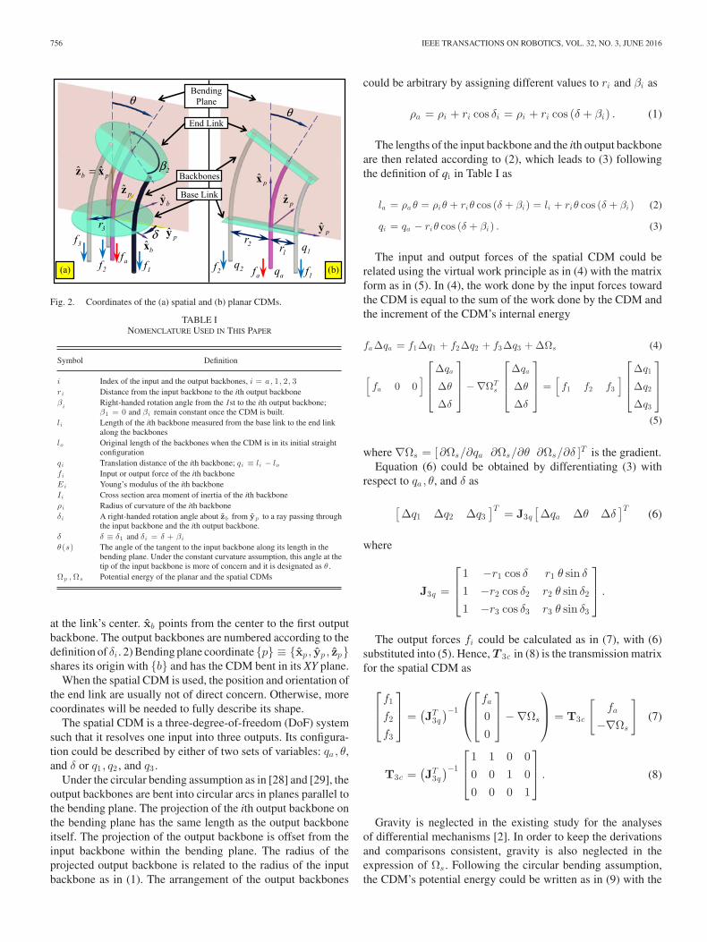
Fig. 7. Three-fingered grippers actuated by (a) spatial CDM and (b) twoserially connected planar CDMs.
force f1 was read and the ratio η = f1/fa was recorded. Themeasurement results are plotted as in Fig. 6(b) for the compari-son to the theoretical results in Fig. 3.
From the experimental results in Fig. 6, it could be seen thatthe discrepancy between the theoretic force ratio η and the ac-tual value varies from –0.10 to 0.10. Several reasons could con-tributed to the discrepancy, such as uncertainties in the materialproperties and fabrication tolerances. In the CDMs’ kinetostaticanalyses, the backbone shapes are assumed to be circular. Thisassumption is of less accuracy when the backbones are heavilypushed or pulled. In addition, this assumption would be furtheraffected by gravity when the CDMs are longer (qi increases).The discrepancy is bigger in Fig. 6 for bigger qi . In order tomaintain the force transmission properties in (7) and (16) tobe accurate, two criteria should be followed if one tries to im-plement the spatial and the planar CDMs: 1) a CDM shouldbe kept as short as possible to a point that plastic deforma-tions do not occur and 2) the forces on the backbones shouldbe kept reasonably below critical loadings for buckling. Other-wise, more accurate modeling of the backbones and calibrationsof the CDM constructions might be needed to better describethe force transmission properties.
B. Gripper Performance Characterizations
The spatial CDM resolves one input into three outputs, whilethe planar CDM is essentially equivalent to the pulley or thelinkage-based KDMs. A main advantage of using CDMs is thedesign’s compactness and structural simplicity. This has beenpartially demonstrated by the single-actuator prosthetic handdesign and its experimentation in [26].
This section further presents the design and experimenta-tion of two three-fingered grippers actuated by a spatial CDM(Gripper-A) and two serially stacked planar CDMs (Gripper-B),as shown in Fig. 7. Hopefully, the grippers’ simple constructionwould inspire more CDM-based mechanism designs.
The fingers in Gripper-A and Gripper-B are identical, as inFig. 7(c). Lengths of the distal and proximal phalanges are 60and 70 mm, respectively. Motions of the J1 and the J2 joints are
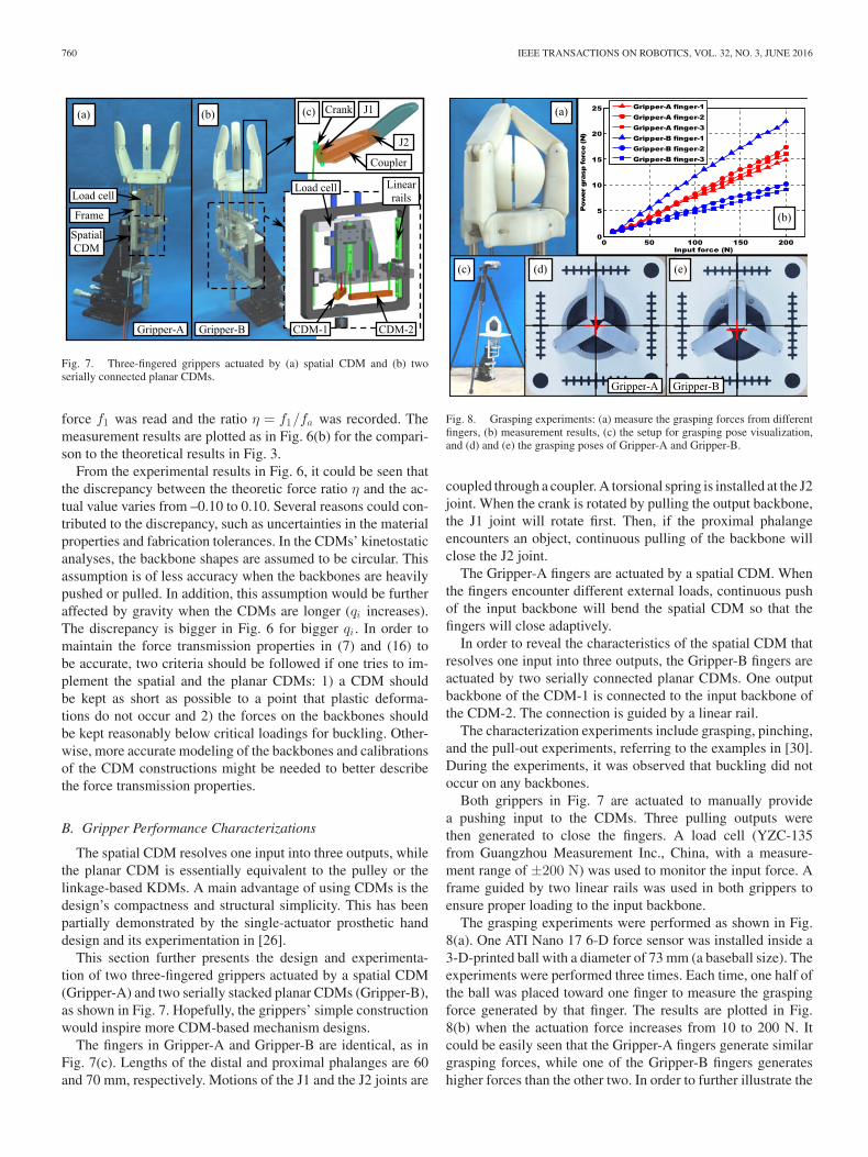
Fig. 8. Grasping experiments: (a) measure the grasping forces from differentfingers, (b) measurement results, (c) the setup for grasping pose visualization,and (d) and (e) the grasping poses of Gripper-A and Gripper-B.
coupled through a coupler. A torsional spring is installed at the J2joint. When the crank is rotated by pulling the output backbone,the J1 joint will rotate first. Then, if the proximal phalangeencounters an object, continuous pulling of the backbone willclose the J2 joint.
The Gripper-A fingers are actuated by a spatial CDM. Whenthe fingers encounter different external loads, continuous pushof the input backbone will bend the spatial CDM so that thefingers will close adaptively.
In order to reveal the characteristics of the spatial CDM thatresolves one input into three outputs, the Gripper-B fingers areactuated by two serially connected planar CDMs. One outputbackbone of the CDM-1 is connected to the input backbone ofthe CDM-2. The connection is guided by a linear rail.
The characterization experiments include grasping, pinching,and the pull-out experiments, referring to the examples in [30].During the experiments, it was observed that buckling did notoccur on any backbones.
Both grippers in Fig. 7 are actuated to manually providea pushing input to the CDMs. Three pulling outputs werethen generated to close the fingers. A load cell (YZC-135from Guangzhou Measurement Inc., China, with a measure-ment range of ±200 N) was used to monitor the input force. Aframe guided by two linear rails was used in both grippers toensure proper loading to the input backbone.
The grasping experiments were performed as shown in Fig.8(a). One ATI Nano 17 6-D force sensor was installed inside a3-D-printed ball with a diameter of 73 mm (a baseball size). Theexperiments were performed three times. Each time, one half ofthe ball was placed toward one finger to measure the graspingforce generated by that finger. The results are plotted in Fig.8(b) when the actuation force increases from 10 to 200 N. Itcould be easily seen that the Gripper-A fingers generate similargrasping forces, while one of the Gripper-B fingers generateshigher forces than the other two. In order to further illustrate the

IEEE TRANSACTIONS ON ROBOTICS, VOL. 32, NO. 3, JUNE 2016 761
Fig. 9. Pinching experiments: (a) measure the pinching forces from differentfingers, (b) measurement results, and (c) failed pinch on Gripper-B.
Fig. 10. Pull-out experiments. (a) Setup. (b) Measurement results.
difference, the grasping poses of the two grippers are visualizedas in Fig. 8(c). The ball grasped is a baseball painted black forbetter visualization. It could be seen from Fig. 8(d) and (e) thatGripper-B pushes the ball aside due to the imbalanced outputsfrom the two serially connected planar CDMs.
The pinching experiments were performed as shown in Fig.9(a). The ATI Nano 17 force sensor was installed inside an-other 3-D-printed ball with a diameter of 40 mm. The ball wasagain placed toward each finger to measure the pinching forcegenerated by that finger. The results of the pinching forces ofGripper-A are plotted in Fig. 9(b) when the actuation force in-creases from 50 to 200 N. The pinching experiments were notsuccessful for Gripper-B because one finger generated higherforces and it always pushed the ball out, as in Fig. 9(c).
The pinching forces in Fig. 9(b) are relatively small, mainlybecause the crank’s moment-arm length in Fig. 7(c) is aboutone-tenth of the finger length. Furthermore, part of the inputforce is used to deform the CDM. The CDM inherently acts as areservoir of energy, whereas a KDM needs to install additionalsprings for this feature. When the scales of the gripper and theCDM are increased, the CDM might absorb a bigger portionof the input energy. A CDM is probably more suitable for lightloads with the input force from zero to a few hundred newtons.
The pull-out experiments were performed, as shown in Fig.10(a). The grippers were actuated by hanging weights to theinput backbone. The total input forces varied from 12 to 102 N.A baseball was grasped and pulled out. The pull-out motion wasrealized by a lead screw and the pull-out force was measured
using a force gauge (HF-200 from Yueqing Aliyiqi InstrumentCo. China with a built-in function for peak force measurementand a range of ±200 N).
The pull-out forces are plotted in Fig. 10(b). From the grasp-ing experiments, it is known that Gripper-B would push thegrasped baseball aside. This outcome actually helped Gripper-B to achieve a higher pull-out force under the same input. If thepull-out direction leans toward the weaker fingers of Gripper-B,the pull-out forces might be reduced.
V. CONCLUSION
This paper has proposed to categorize differential mecha-nisms into KDMs and CDMs. KDMs generate differential out-puts via motions of the kinematic pairs, while CDMs utilizethe redistributions and/or deformations of their own materialsand structures to generate differential outputs. The IFToMMterminology could be expanded to cover the CDMs.
A planar CDM and a spatial CDM is then introduced. Kine-tostatic analyses and experimental characterizations are carriedout to reveal their force transmission properties. The equiv-alency between the planar CDM and two existing KDMs isindicated. On the other hand, the spatial CDM resolves oneinput into three outputs in an inherently isotropic way. This fea-ture was demonstrated via a series of experiments performed ontwo three-fingered grippers driven by one spatial CDM and twoserially connected planar CDMs.
Due to the inherent compliance and deforming properties, theCDMs might not be ideal for large outputs. However, the simpleconstruction and cheap fabrication of the CDMs could indeedbe advantageous. Following the analyses and experiments pre-sented in this paper, hopefully one could design other CDMswith various force transmission responses and properties to re-alize compact, affordable, and adaptive mechanical systems.
REFERENCES
[1] IFToMM, “Standardization of terminology,” in IFToMM Dictionaries,International Federation for the Promotion of Mechanism and MachineScience, 2007.
[2] L. Birglen and C. M. Gosselin, “Force analysis of connected differentialmechanisms: Application to grasping,” Int. J. Robot. Res., vol. 25, no. 10,pp. 1033–1046, Oct. 2006.
[3] C. Gosselin, F. Pelletier, and T. Laliberte, “An anthropomorphic underac-tuated robotic hand with 15 DoFs and a single actuator,” in Proc. IEEEInt. Conf. Robot. Autom., Pasadena, CA, USA, 2008, pp. 749–754.
[4] M. Baril, T. Laliberte, C. Gosselin, and F. Routhier, “On the design ofa mechanically programmable underactuated anthropomorphic prostheticgripper,” J. Mech. Des., vol. 135, no. 12, p. 121008–1, Oct. 2013.
[5] J. T. Belter and A. M. Dollar, “Novel differential mechanism enabling twoDOF from a single actuator: Application to a prosthetic hand,” in Proc.IEEE Int. Conf. Rehabil. Robot., Seattle, WA, USA, 2013, pp. 1–6.
[6] N. Fukaya, S. Toyama, T. Asfour, and R. Dillmann, “Design of theTUAT/Karlsruhe humanoid hand,” in Proc. IEEE/RSJ Int. Conf. Intell.Robots Syst., Takamatsu, Japan, 2000, pp. 1754–1759.
[7] Y. Kamikawa and T. Maeno, “Underactuated five-finger prosthetic handinspired by grasping force distribution of humans,” in Proc. IEEE/RSJ Int.Conf. Intell. Robots Syst., Nice, France, 2008, pp. 717–722.
[8] L. Birglen, T. Laliberte, and C. Gosselin, “Design and control of the Lavalunderactuated hands,” in Underactuated Robotic Hands, vol. 40. Berlin,Germany: Springer, 2008, pp. 171–207.
[9] V. Begoc, S. Krut, E. Dombre, C. Durand, and F. Pierrot, “Mechanicaldesign of a new pneumatically driven underactuated hand,” in Proc. IEEEInt. Conf. Robot. Autom., Roma, Italy, 2007, pp. 927–933.

762 IEEE TRANSACTIONS ON ROBOTICS, VOL. 32, NO. 3, JUNE 2016
[10] C. Y. Brown and H. H. Asada, “Inter-finger coordination and posturalsynergies in robot hands via mechanical implementation of principal com-ponents analysis,” in Proc. IEEE/RSJ Int. Conf. Intell. Robots Syst., SanDiego, CA, USA, 2007, pp. 2877–2882.
[11] W. Chen, C. Xiong, and S. Yue, “Mechanical implementation of kinematicsynergy for continual grasping generation of anthropomorphic hand,”IEEE/ASME Trans. Mechatronics, vol. 20, no. 3, pp. 1249–1263, May2015.
[12] S. Li, X. Sheng, H. Liu, and X. Zhu, “Design of a myoelectric prosthetichand implementing postural synergy mechanically,” Ind. Robot: An Int.J., vol. 41, no. 5, pp. 447–455, 2014.
[13] K. Xu, J. Zhao, Y. Du, X. Sheng, and X. Zhu, “Design and posturalsynergy synthesis of a prosthetic hand for a manipulation task,” in Proc.IEEE/ASME Int. Conf. Adv. Intell. Mechatron., Wollongong, NSW, Aus-tralia, 2013, pp. 56–62.
[14] K. Xu, H. Liu, Y. Du, and X. Zhu, “Design of an underactuated anthropo-morphic hand with mechanically implemented postural synergies,” Adv.Robot., vol. 28, no. 21, pp. 1459–1474, Nov. 2014.
[15] L. Birglen and C. M. Gosselin, “Kinetostatic analysis of underactuatedfingers,” IEEE Trans. Robot. Autom., vol. 20, no. 2, pp. 211–221, Apr.2004.
[16] S. Krut, “A force-isotropic underactuated finger,” in Proc. IEEE Int. Conf.Robot. Autom., Barcelona, Spain, 2005, pp. 2314–2319.
[17] M. C. Carrozza, G. Cappiello, S. Micera, B. B. Edin, L. Beccai, andC. Cipriani, “Design of a cybernetic hand for perception and action,” Biol.Cybern., vol. 95, no. 6, pp. 629–644, 2006.
[18] L. Zollo, S. Roccella, E. Guglielmelli, M. C. Carrozza, and P. Dario,“Biomechatronic design and control of an anthropomorphic artificial handfor prosthetic and robotic applications,” IEEE/ASME Trans. Mechatron.,vol. 12, no. 4, pp. 418–429, Aug. 2007.
[19] S. A. Dalley, T. E. Wiste, T. J. Withrow, and M. Goldfarb, “Design ofa multifunctional anthropomorphic prosthetic hand with extrinsic actua-tion,” IEEE/ASME Trans. Mechatron., vol. 14, no. 6, pp. 699–706, Nov.2009.
[20] W. Townsend, “The BarrettHand Grasper—Programmably flexible parthandling and assembly,” Ind. Robot: Int. J., vol. 27, no. 3, pp. 181–188,2000.
[21] A. Pringle, “Artificial hand,” U.S. Patent 1 324 564, 1919.[22] N. Decheva, W. L. Cleghorn, and S. Naumann, “Multiple finger, passive
adaptive grasp prosthetic hand,” Mech. Mach. Theory, vol. 36, no. 10,pp. 1157–1173, Oct. 2001.
[23] B. Massa, S. Roccella, M. C. Carrozza, and P. Dario, “Design anddevelopment of an underactuated prosthetic hand,” in Proc. IEEEInt. Conf. Robot. Autom., Washington, DC, USA, 2002, pp. 3374–3379.
[24] M. C. Carrozza et al., “A cosmetic prosthetic hand with tendon drivenunder-actuated mechanism and compliant joints: Ongoing research andpreliminary results,” in Proc. IEEE Int. Conf. Robot. Autom., Barcelona,Spain, 2005, pp. 2661–2666.
[25] A. M. Dollar and R. D. Howe, “The highly adaptive SDM hand: design andperformance evaluation,” Int. J. Robot. Res., vol. 29, no. 5, pp. 585–597,Apr. 2010.
[26] K. Xu, H. Liu, Z. Liu, Y. Du, and X. Zhu, “A single-actuatorprosthetic hand using a continuum differential mechanism,” in Proc.IEEE Int. Conf. Robot. Autom., Seattle, WA, USA, 2015, pp. 6457–6462.
[27] X. Wang and J. K. Mills, “Dynamic modeling of a flexible-link planarparallel platform using a substructuring approach,” Mech. Mach. Theory,vol. 41, no. 6, pp. 671–687, Jun. 2006.
[28] K. Xu and N. Simaan, “An investigation of the intrinsic force sensingcapabilities of continuum robots,” IEEE Trans. Robot., vol. 24, no. 3,pp. 576–587, Jun. 2008.
[29] K. Xu and N. Simaan, “Analytic formulation for the kinematics, stat-ics and shape restoration of multibackbone continuum robots via el-liptic integrals,” J. Mech. Robot., vol. 2, no. 011006, pp. 1–13, Feb.2010.
[30] G. Carbone, Grasping in Robotics, vol. 10. London, U.K.: Springer, 2013.

![Authentic TAI · PDF file8-9pm Hsing I Chuan by Huan Kung Fu instructor from Kai Feng, He Nan, China 1st place in Basic Kung Fu competition in Kai Feng Thur [ David Watts ]](https://img.pdfslide.us/doc/110x75/5a70d6177f8b9aa2538c69b8/authentic-tai-chiwwwhuanstaichicomflyer040915htcposterpdfpdf.jpg)