Embed Size (px)
Citation preview
1 MARCH 2012 TS TIDINGS
TECHNICAL SERVICES / PSSR
KAHALGAON STPP MARCH 2012 VOLUME : 15.10
Published by Technical Services / PSSR For internal circulation
HIGHLIGHTS BELLARY 500 MW UNIT 2:
COAL FIRING WAS DONE ON 22.03.12
UNIT REACHED FULL LOAD ON 23.03.12.
CPCL PHASE 3 - UNIT 4: GT 4 FSNL REACHED ON 28.03.12. UNIT WAS SYNCHRONISED ON 29.03.12 AND LOADED TO 3.5 MW
SIMHADRI STAGE II, 2 X 500 MW, UNIT 4:
UNIT WAS SYNCHRONISED ON 30.03.12 WITH FULL LOAD ON SAME DAY.
VALLUR 3 X 500 MW, UNIT 1: UNIT WAS SYNCHRONIZED ON 09.03.12 WITH COAL FIRING. UNIT REACHED FULL LOAD ON 28.03.12.
KAKATIYA 500 MW, UNIT 1:
TG PG TEST WAS COMPLETED.
2 MARCH 2012 TS TIDINGS
TECHNICAL SERVICES / PSSR
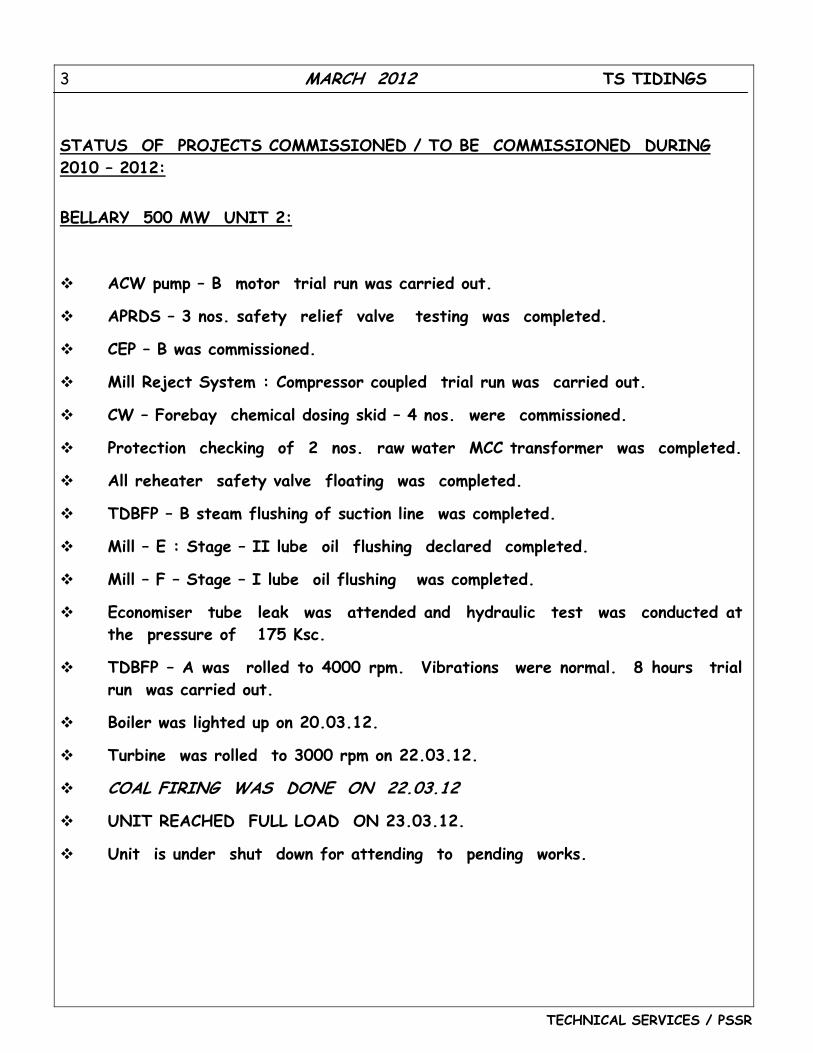
INSIDE
1. STATUS OF PROJECTS COMMISSIONED / TO BE COMMISSIONED DURING 2010 - 2012.
2. SERVICE RENDERED TO OTHER REGIONS/SAS/PROJECTS AFTER CONTRACT
CLOSING/CUSTOMER TRAINING.
3. APPRECIATION FROM CUSTOMER FOR SERVICES RENDERED.
4. FEED BACK ON EQUIPMENTS FROM SITES.
5. LET US KNOW. A COMMISSIONING EXPERIENCE
Feed backs and suggestions from all departments of BHEL for improvement of TS TIDINGS are welcome and may please be addressed to ADDL. GENERAL MANAGER (TSX)/BHEL-PSSR/CHENNAI
3 MARCH 2012 TS TIDINGS
TECHNICAL SERVICES / PSSR
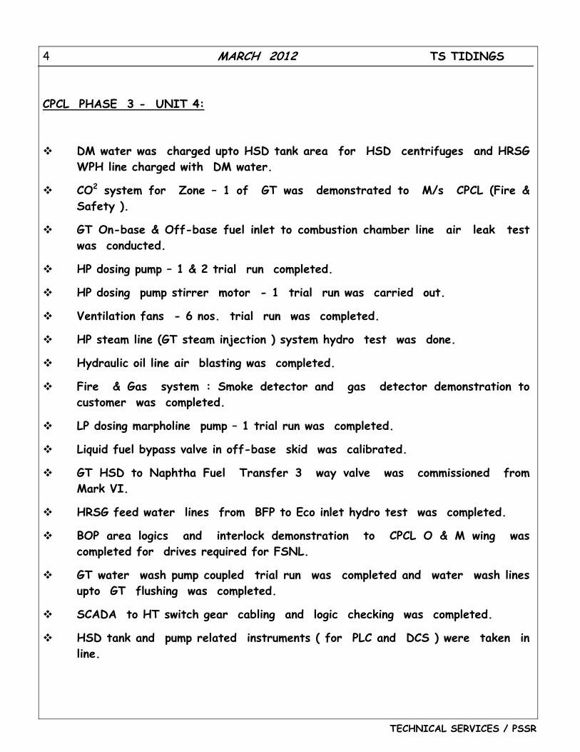
STATUS OF PROJECTS COMMISSIONED / TO BE COMMISSIONED DURING 2010 – 2012: BELLARY 500 MW UNIT 2:
ACW pump – B motor trial run was carried out.
APRDS – 3 nos. safety relief valve testing was completed.
CEP – B was commissioned.
Mill Reject System : Compressor coupled trial run was carried out.
CW – Forebay chemical dosing skid – 4 nos. were commissioned.
Protection checking of 2 nos. raw water MCC transformer was completed.
All reheater safety valve floating was completed.
TDBFP – B steam flushing of suction line was completed.
Mill – E : Stage – II lube oil flushing declared completed.
Mill – F – Stage – I lube oil flushing was completed.
Economiser tube leak was attended and hydraulic test was conducted at the pressure of 175 Ksc.
TDBFP – A was rolled to 4000 rpm. Vibrations were normal. 8 hours trial run was carried out.
Boiler was lighted up on 20.03.12.
Turbine was rolled to 3000 rpm on 22.03.12.
COAL FIRING WAS DONE ON 22.03.12
UNIT REACHED FULL LOAD ON 23.03.12.
Unit is under shut down for attending to pending works.
4 MARCH 2012 TS TIDINGS
TECHNICAL SERVICES / PSSR
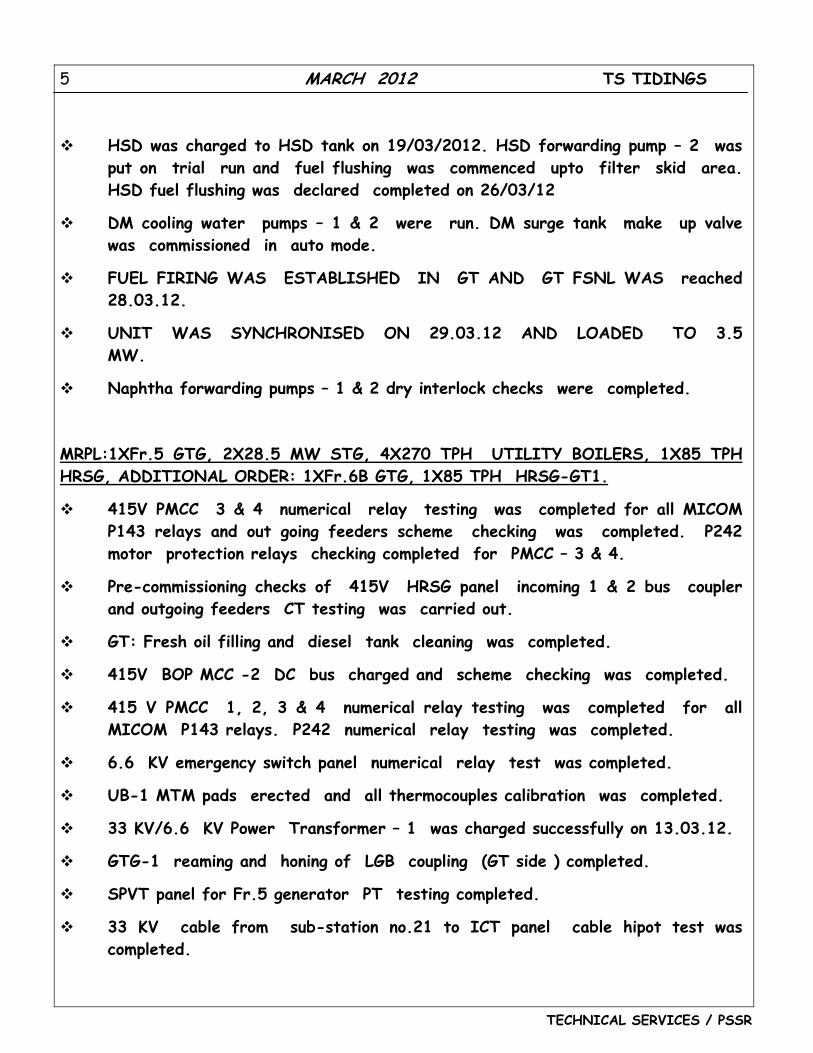
CPCL PHASE 3 - UNIT 4:
DM water was charged upto HSD tank area for HSD centrifuges and HRSG WPH line charged with DM water.
CO2 system for Zone – 1 of GT was demonstrated to M/s CPCL (Fire & Safety ).
GT On-base & Off-base fuel inlet to combustion chamber line air leak test was conducted.
HP dosing pump – 1 & 2 trial run completed.
HP dosing pump stirrer motor - 1 trial run was carried out.
Ventilation fans - 6 nos. trial run was completed.
HP steam line (GT steam injection ) system hydro test was done.
Hydraulic oil line air blasting was completed.
Fire & Gas system : Smoke detector and gas detector demonstration to customer was completed.
LP dosing marpholine pump – 1 trial run was completed.
Liquid fuel bypass valve in off-base skid was calibrated.
GT HSD to Naphtha Fuel Transfer 3 way valve was commissioned from Mark VI.
HRSG feed water lines from BFP to Eco inlet hydro test was completed.
BOP area logics and interlock demonstration to CPCL O & M wing was completed for drives required for FSNL.
GT water wash pump coupled trial run was completed and water wash lines upto GT flushing was completed.
SCADA to HT switch gear cabling and logic checking was completed.
HSD tank and pump related instruments ( for PLC and DCS ) were taken in line.
5 MARCH 2012 TS TIDINGS
TECHNICAL SERVICES / PSSR
HSD was charged to HSD tank on 19/03/2012. HSD forwarding pump – 2 was put on trial run and fuel flushing was commenced upto filter skid area. HSD fuel flushing was declared completed on 26/03/12
DM cooling water pumps – 1 & 2 were run. DM surge tank make up valve was commissioned in auto mode.
FUEL FIRING WAS ESTABLISHED IN GT AND GT FSNL WAS reached 28.03.12.
UNIT WAS SYNCHRONISED ON 29.03.12 AND LOADED TO 3.5 MW.
Naphtha forwarding pumps – 1 & 2 dry interlock checks were completed.
MRPL:1XFr.5 GTG, 2X28.5 MW STG, 4X270 TPH UTILITY BOILERS, 1X85 TPH HRSG, ADDITIONAL ORDER: 1XFr.6B GTG, 1X85 TPH HRSG-GT1.
415V PMCC 3 & 4 numerical relay testing was completed for all MICOM P143 relays and out going feeders scheme checking was completed. P242 motor protection relays checking completed for PMCC – 3 & 4.
Pre-commissioning checks of 415V HRSG panel incoming 1 & 2 bus coupler and outgoing feeders CT testing was carried out.
GT: Fresh oil filling and diesel tank cleaning was completed.
415V BOP MCC -2 DC bus charged and scheme checking was completed.
415 V PMCC 1, 2, 3 & 4 numerical relay testing was completed for all MICOM P143 relays. P242 numerical relay testing was completed.
6.6 KV emergency switch panel numerical relay test was completed.
UB-1 MTM pads erected and all thermocouples calibration was completed.
33 KV/6.6 KV Power Transformer – 1 was charged successfully on 13.03.12.
GTG-1 reaming and honing of LGB coupling (GT side ) completed.
SPVT panel for Fr.5 generator PT testing completed.
33 KV cable from sub-station no.21 to ICT panel cable hipot test was completed.
6 MARCH 2012 TS TIDINGS
TECHNICAL SERVICES / PSSR
GT Frame – 5 Diverter damper seal air fan - 4 hours trial run completed.
Interconnecting transformer ( 33 KV/ 33 KV ) – Back charged successfully on 24.03.12.
33 KV panel No –10, CDU/VDU substation no.33: P521/P595 relay communication established and line differential protection was successfully charged.
33 KV panel TIE - C to TIE – A cable hipot test and interlock checking completed and charged from C to A.
HRSG -2 MTM thermocouple ( 44 nos. ) calibration was completed.
GT 1: Guillotine damper seal air fan 1 & 2 - 4 hours trial run completed.
NEYVELI TS II EXP CFBC, 2 X 250 MW, UNIT 1:
Hydraulic test of feed water circuit was done in the presence of Boiler Inspector on 10.03.12.
CFBC was lighted up at 0033 hrs. on 13.03.12. After achieving steam purity, STG (Steam Turbo Generator ) rolled and synchronized at 0547 hrs. on 14.03.12. Lignite firing was done and LP heaters were charged.
Unit was running around 120 MW. Unit was boxed up on 20.03.12 due to SH 1.2 in FBHE 2 tube leakage. CFBC is on cooling mode.
NEYVELI TS II EXP CFBC, 2 X 250 MW, UNIT 2:
LT panel : relay testing was completed.
ACW – 2A motor trial run was completed.
Preparatory work for stage – II lube oil flushing was completed and stage-II oil flushing was started on 23.03.12.
BFP-2C – Oil filling was completed, bumped and identified leaks were attended.
Seal oil piping air blasting was completed.
7 MARCH 2012 TS TIDINGS
TECHNICAL SERVICES / PSSR
RINL:
Signal checking between blower and MAXDNA system was completed.
Turbine solo run was carried out again on 03.03.12 in the presence of BHEL,Hyderabad engineer.
PA fan – B : Stage – II oil flushing was completed.
Modification of ignitor assembly was completed.
SG-6: LDO pipes hydro test was completed.
Scanner guide pipe modification was completed .
APH soot blower motor trial run was carried out.
Alignment between Turbine and blower was completed.
Blower discharge line free joint checking was completed.
Soot blower lance checking completed for all blowers.
Ignitor advance / retract position checking was completed in all corners of three elevations.
LVS ( Large Video Screen ) system was commissioned.
Turbine bearing was boxed up. Blower front and rear bearing box up work completed.
BFD line : HP heater 1 & 2 inlet line steam blowing was completed.
ESP – B pass – 2 nos. of EERM motor trial run was completed.
PA fan stage – I lube oil flushing was completed.
SIMHADRI STAGE II, 2 X 500 MW, UNIT 3:
Unit is presently running at full load.
Mills PG test team is at site to conduct 100% capacity test of one mill.
8 MARCH 2012 TS TIDINGS
TECHNICAL SERVICES / PSSR
SIMHADRI STAGE II, 2 X 500 MW, UNIT 4:
Mill – B: 8 hours trial run, Mill – D 8 hours motor trial run & DC scanner fan motor trial was completed.
TDBFP A suction line upto suction valve and condensate flushing declared completed. Lube oil flushing and piping normalization work was completed. DCEOP motor trial run and JOP motor decoupled trial run completed.
Mill – C: Stage-II lube oil flushing declared completed, 8 hours trial run carried out and ring roll setting was done.
ID fan – A: Lube oil lines acid cleaning was completed.
Coal feeder A & B: 4 hours trial run and belt tracking and calibration completed.
Boiler Air Tightness Test (ATT) was carried out upto Air preheater.
Seal air fan – A & B – 4 hours coupled trial run was carried out.
Control fluid : ATT was done with all circuits charged. Pumps were run and circulation bypassing CF cooler was established. 8 bar hydro test was done. TCV was locally commissioned.
Mill – D : Stage – 1 lube oil flushing declared completed.
FD fan – A and Mill – E: 8 hours trial run was carried out.
Feeder – C : Calibration was completed.
Mill E – Stage 1 and Mill D - Stage II lube oil flushing declared completed. Mill – E : First 4 hours trial run completed.
HP dosing line hydro test was carried out.
TDBFP – B oil flushing was completed.
HP bypass oil lines air blowing was done and oil filling was completed. HP bypass oil lines air blowing was done and oil filling was completed.
HP bypass : Oil supply unit 1 & 2 pressure switch setting and pump relief valve setting completed. Oil flushing of P & I lines completed including 22 & 5 micron filters.
Seal oil system was established.
9 MARCH 2012 TS TIDINGS
TECHNICAL SERVICES / PSSR
Debris filter inlet and outlet actuator – 4 nos. were locally commissioned.
Boiler Hydro test was carried out upto 138 Ksc.
Mill – D: 8 hours trial run and ring roll setting completed.
Mills - A, B & C clean air flow test was conducted.
FD fan A & ID fan A : Stage II lube oil flushing completed.
TG was put on barring gear on 22.03.12.
Cooling water system : Valves of condenser local commissioning was done.
FD fan A : 8 hours trial run was completed.
PAPH – B: Flue gas inlet gates local operation was completed.
LP water injector valve actuator was commissioned.
ID fan – A: Motor decoupled trial run completed. IGV actuator remote and local operation completed.
PAPH – A: Main drive motor decoupled 4 hours trial run completed.
ID fan – A: 8 hours trial run completed.
UNIT WAS SYNCHRONISED ON 30.03.12 and full load was achieved on the same day. Maximum loaded upto 517MW.
VALLUR 3 X 500 MW, UNIT 1:
ACW pump B: 4 hours trial run was completed. Feeder – C calibration was completed. Generator Air Tightness Test was completed; Mill - A: Trial run and ring roller setting was done. Mill – B : Trial run
was carried out. Seal air fan B : Motor decoupled trial run was done. UNIT WAS SYNCHRONIZED ON 09.03.12 WITH COAL FIRING AND
LOADED TO 50 MW. FD fan – A : Stage 1 lube oil flushing was completed. Mill E : II stage lube oil flushing was completed. Clean air flow test was
carried out.
10 MARCH 2012 TS TIDINGS
TECHNICAL SERVICES / PSSR
TDBFP A : Lube oil flushing declared completed. Solo run was carried out and over speed test completed.
Mills A, B & C Clean air flow test was carried out. Mill – D : II stage lube oil flushing completed. 8 hours trial run
completed. Clean air flow test was carried out. SAPH – Lube oil flushing of support bearing and guide bearing was
completed. DC-EOP motor trial run and JOP motor decoupled trial run completed. TDBFP – A was put on barring gear on 20.03.12. Positioning of hot air and cold air damper actuators was completed. Boiler was lighted up on 27.03.12. Unit Reached Full Load and Maximum Load raised to 513 MW on 28.03.12.
KAKATIYA 1 X 500 MW UNIT 1 :
TG PG test was completed ( 100% load heat rate test, 100% output test and Valve wide open test were completed).
SERVICES RENDERED TO CUSTOMER /SAS/MUs:
--- NIL ---
CUSTOMER TRAINING & TECHNICAL PAPER PRESENTED:
--- NIL ---
APPRECIATION FROM CUSTOMER FOR SERVICES RENDERED :
--- NIL ---
11 MARCH 2012 TS TIDINGS
TECHNICAL SERVICES / PSSR
FEED BACK NO.1
PROJECT: RINL TURBO BLOWER #4, VISHAKAPATNAM
PROBLEM: HYDRAULIC BARRING GEAR DEVICE RATCHET MECHANISM FOULING WITH RATCHET WHEEL DURING ROLLING OF TURBINE.
Description of barring gear mechanism:
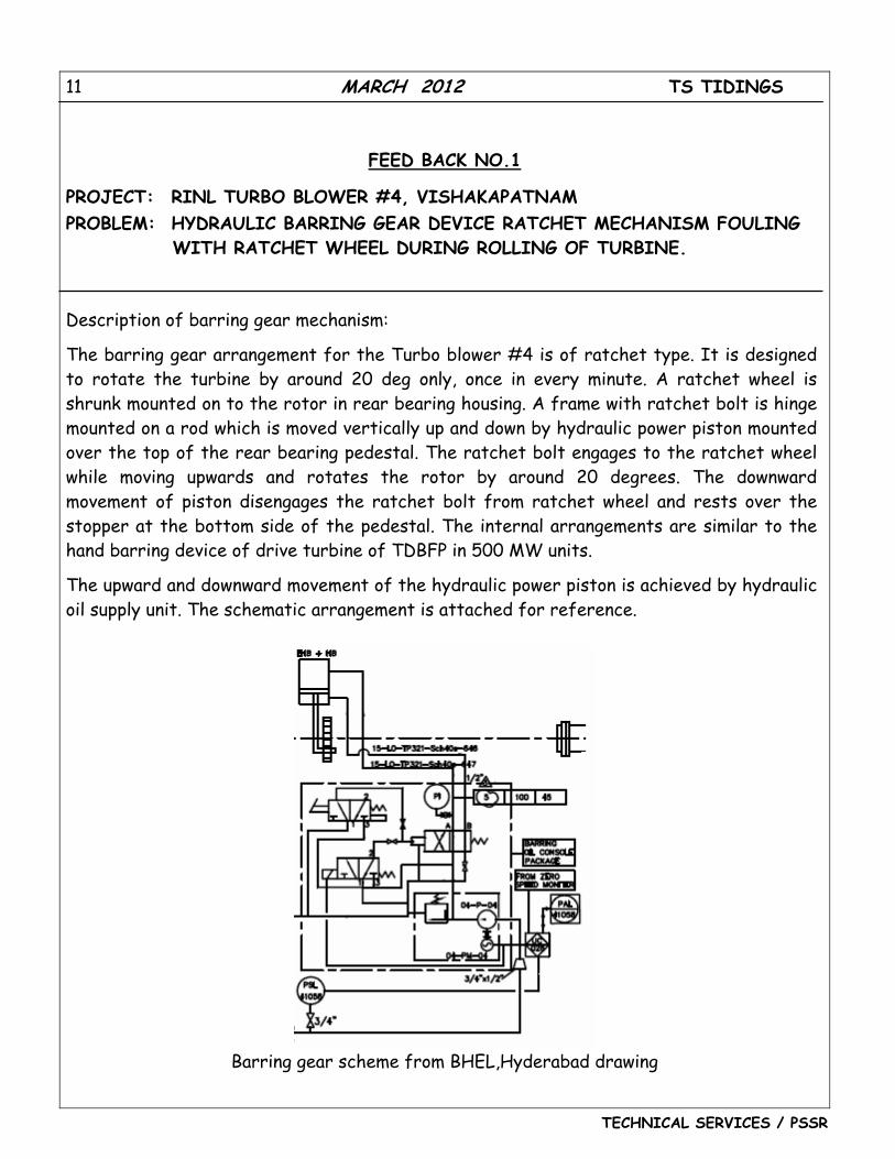
The barring gear arrangement for the Turbo blower #4 is of ratchet type. It is designed to rotate the turbine by around 20 deg only, once in every minute. A ratchet wheel is shrunk mounted on to the rotor in rear bearing housing. A frame with ratchet bolt is hinge mounted on a rod which is moved vertically up and down by hydraulic power piston mounted over the top of the rear bearing pedestal. The ratchet bolt engages to the ratchet wheel while moving upwards and rotates the rotor by around 20 degrees. The downward movement of piston disengages the ratchet bolt from ratchet wheel and rests over the stopper at the bottom side of the pedestal. The internal arrangements are similar to the hand barring device of drive turbine of TDBFP in 500 MW units.
The upward and downward movement of the hydraulic power piston is achieved by hydraulic oil supply unit. The schematic arrangement is attached for reference.
Barring gear scheme from BHEL,Hyderabad drawing
12 MARCH 2012 TS TIDINGS
TECHNICAL SERVICES / PSSR
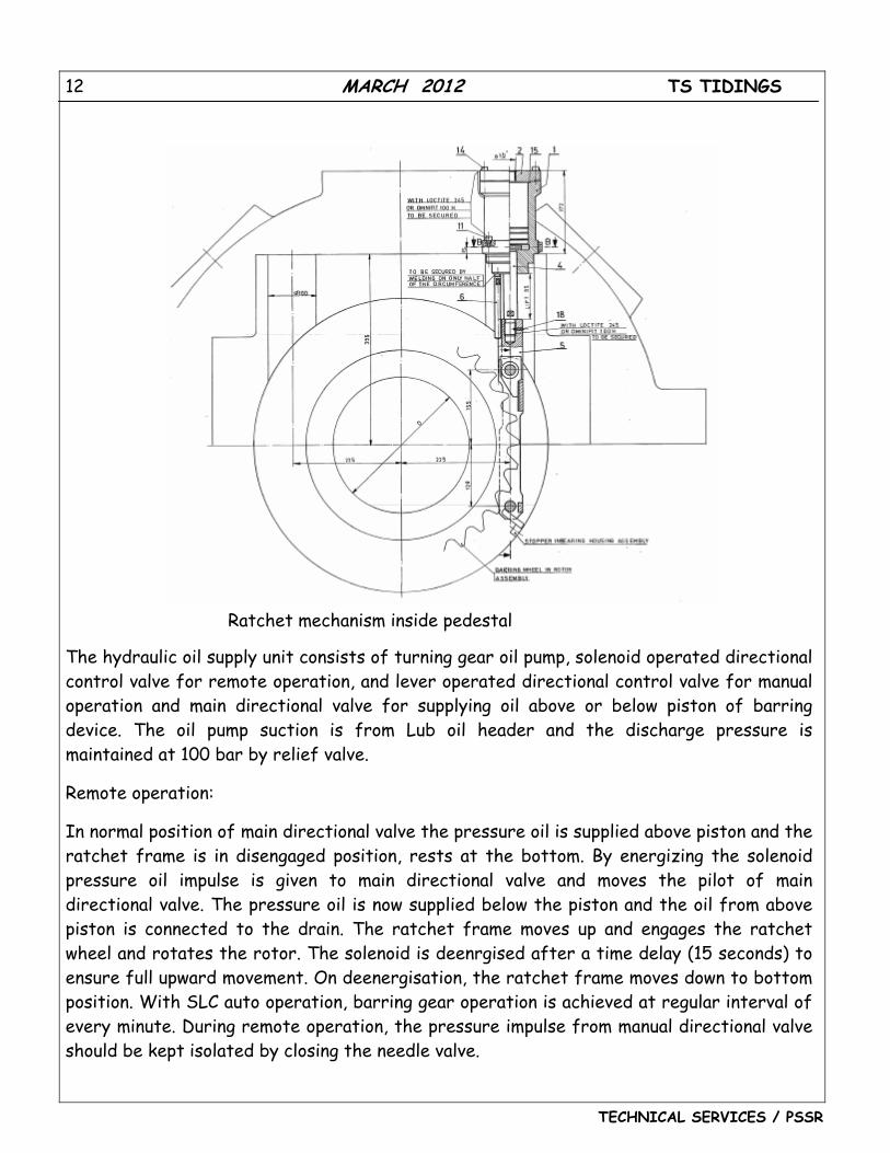
Ratchet mechanism inside pedestal
The hydraulic oil supply unit consists of turning gear oil pump, solenoid operated directional control valve for remote operation, and lever operated directional control valve for manual operation and main directional valve for supplying oil above or below piston of barring device. The oil pump suction is from Lub oil header and the discharge pressure is maintained at 100 bar by relief valve.
Remote operation:
In normal position of main directional valve the pressure oil is supplied above piston and the ratchet frame is in disengaged position, rests at the bottom. By energizing the solenoid pressure oil impulse is given to main directional valve and moves the pilot of main directional valve. The pressure oil is now supplied below the piston and the oil from above piston is connected to the drain. The ratchet frame moves up and engages the ratchet wheel and rotates the rotor. The solenoid is deenrgised after a time delay (15 seconds) to ensure full upward movement. On deenergisation, the ratchet frame moves down to bottom position. With SLC auto operation, barring gear operation is achieved at regular interval of every minute. During remote operation, the pressure impulse from manual directional valve should be kept isolated by closing the needle valve.
13 MARCH 2012 TS TIDINGS
TECHNICAL SERVICES / PSSR
Manual operation:
A directional valve similar to solenoid operated valve is provided with lever operation instead of solenoid. By lever operation, the pressure impulse will be given to the main directional valve and barring gear piston is operated. During manual operation, isolation valve in the impulse line from remote system should be kept closed. Problem detail:
It was practiced normally to raise the speed to 50 RPM only initially to ensure controlled speeding up by EHTC and subsequently speed reference is raised to first warming up speed of 500 RPM. During rolling of the machine to 50 RPM, ratchet mechanism fouling noise was observed from the rear bearing housing. The machine was stopped immediately. There was no indication provided outside the pedestal, to know the position of ratchet mechanism. It was suspected that the barring gear oil pump was switched off before the ratchet frame moving down to bottom position. The barring gear pump was switched ‘ON’ and after few cycles of barring, the pump was switched OFF after a time delay. Again while rolling, the fouling noise was observed. The barring oil pump was started immediately and found that the noise stopped. Whenever pump was stopped, the ratchet frame was moving up causing fouling and noise. The baffle plate of rear pedestal was removed and observations made during switching OFF of the oil pump. It moves up a little to cause fouling. The direction control valve pilots were serviced and put back. The problem was still persisting. Analysis:
During initial commissioning, it was observed that the operation of the barring gear was reverse with respect to solenoid operation. That is when the solenoid was energized, the ratchet was moving down and when the solenoid was deenergised, the ratchet was moving up. To achieve the phenomena as per scheme and for fail safe operation, the piping connections for above piston and below piston were just interchanged.
14 MARCH 2012 TS TIDINGS
TECHNICAL SERVICES / PSSR
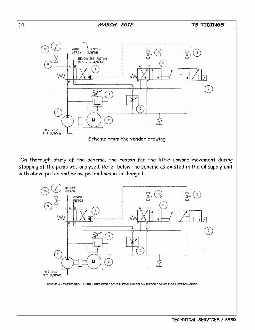
Scheme from the vendor drawing
On thorough study of the scheme, the reason for the little upward movement during stopping of the pump was analysed. Refer below the scheme as existed in the oil supply unit with above piston and below piston lines interchanged.
15 MARCH 2012 TS TIDINGS
TECHNICAL SERVICES / PSSR
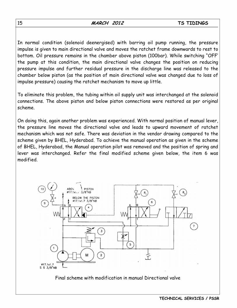
In normal condition (solenoid deenergised) with barring oil pump running, the pressure impulse is given to main directional valve and moves the ratchet frame downwards to rest to bottom. Oil pressure remains in the chamber above piston (100bar). While switching “OFF’ the pump at this condition, the main directional valve changes the position on reducing pressure impulse and further residual pressure in the discharge line was released to the chamber below piston (as the position of main directional valve was changed due to loss of impulse pressure) causing the ratchet mechanism to move up little. To eliminate this problem, the tubing within oil supply unit was interchanged at the solenoid connections. The above piston and below piston connections were restored as per original scheme. On doing this, again another problem was experienced. With normal position of manual lever, the pressure line moves the directional valve and leads to upward movement of ratchet mechanism which was not safe. There was deviation in the vendor drawing compared to the scheme given by BHEL, Hyderabad. To achieve the manual operation as given in the scheme of BHEL, Hyderabad, the Manual operation pilot was removed and the position of spring and lever was interchanged. Refer the final modified scheme given below, the item 6 was modified.
Final scheme with modification in manual Directional valve
16 MARCH 2012 TS TIDINGS
TECHNICAL SERVICES / PSSR
Conclusion: The desired performance of the barring gear operation without fouling was achieved with the modifications summarized below:
1. The inlet and drain connections of the solenoid valve were corrected as per the scheme. This was an assembly mistake by the vendor.
2. The manual operation directional valve positions were deviating in the vendor drawing when compared with drawing of BHEL, Hyderabad. The directional valve position was corrected as per BHEL, Hyderabad scheme.
Courtesy:
1. Shri. M V Baskaran, DGM/Tech services, Chennai
2. Shri. Vasanth Rao Jadav, UCM/RINL Site, Vizag
3. Shri. Debashish Sheth, Sr Engineer/RINL site.
4. Shri. Ardhendu Guin, AE II/RINL Site
17 MARCH 2012 TS TIDINGS
TECHNICAL SERVICES / PSSR
FEED BACK NO. 2
PROJECT: VALLUR UNIT-1 (500 MW) PROBLEM: USING OF E PAC OF ANOTHER ACTUATOR FOR OPERATING OF STEAM BLOWING VALVES WITH NON INTEGARAL ACTUATOR
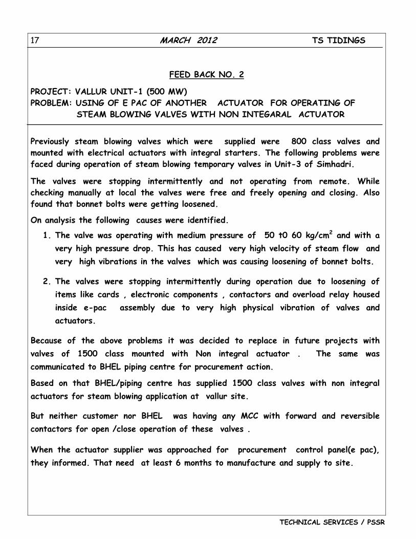
Previously steam blowing valves which were supplied were 800 class valves and mounted with electrical actuators with integral starters. The following problems were faced during operation of steam blowing temporary valves in Unit-3 of Simhadri.
The valves were stopping intermittently and not operating from remote. While checking manually at local the valves were free and freely opening and closing. Also found that bonnet bolts were getting loosened.
On analysis the following causes were identified.
1. The valve was operating with medium pressure of 50 t0 60 kg/cm2 and with a very high pressure drop. This has caused very high velocity of steam flow and very high vibrations in the valves which was causing loosening of bonnet bolts.
2. The valves were stopping intermittently during operation due to loosening of items like cards , electronic components , contactors and overload relay housed inside e-pac assembly due to very high physical vibration of valves and actuators.
Because of the above problems it was decided to replace in future projects with valves of 1500 class mounted with Non integral actuator . The same was communicated to BHEL piping centre for procurement action.
Based on that BHEL/piping centre has supplied 1500 class valves with non integral actuators for steam blowing application at vallur site.
But neither customer nor BHEL was having any MCC with forward and reversible contactors for open /close operation of these valves .
When the actuator supplier was approached for procurement control panel(e pac), they informed. That need at least 6 months to manufacture and supply to site.
18 MARCH 2012 TS TIDINGS
TECHNICAL SERVICES / PSSR
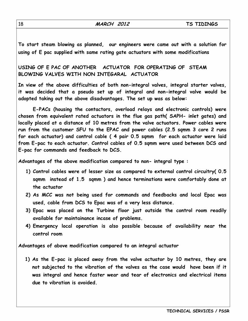
To start steam blowing as planned, our engineers were came out with a solution for using of E pac supplied with same rating gate actuators with some modifications
USING OF E PAC OF ANOTHER ACTUATOR FOR OPERATING OF STEAM BLOWING VALVES WITH NON INTEGARAL ACTUATOR
In view of the above difficulties of both non-integral valves, integral starter valves, it was decided that a pseudo set up of integral and non-integral valve would be adopted taking out the above disadvantages. The set up was as below:
E-PACs (housing the contactors, overload relays and electronic controls) were chosen from equivalent rated actuators in the flue gas path( SAPH- inlet gates) and locally placed at a distance of 10 metres from the valve actuators. Power cables were run from the customer SFU to the EPAC and power cables (2.5 sqmm 3 core 2 runs for each actuator) and control cable ( 4 pair 0.5 sqmm for each actuator were laid from E-pac to each actuator. Control cables of 0.5 sqmm were used between DCS and E-pac for commands and feedback to DCS.
Advantages of the above modification compared to non- integral type :
1) Control cables were of lesser size as compared to external control circuitry( 0.5 sqmm instead of 1.5 sqmm ) and hence terminations were comfortably done at the actuator
2) As MCC was not being used for commands and feedbacks and local Epac was used, cable from DCS to Epac was of a very less distance.
3) Epac was placed on the Turbine floor just outside the control room readily available for maintainance incase of problems.
4) Emergency local operation is also possible because of availability near the control room
Advantages of above modification compared to an integral actuator
1) As the E-pac is placed away from the valve actuator by 10 metres, they are not subjected to the vibration of the valves as the case would have been if it was integral and hence faster wear and tear of electronics and electrical items due to vibration is avoided.
19 MARCH 2012 TS TIDINGS
TECHNICAL SERVICES / PSSR
2) Also the Epac is easily approachable for maintainance and is not subjected to any temperature and hence the life of electrical and electronic items are not decreased. Also trouble shooting is easy as person is not subjected to high temperature during trouble shooting.
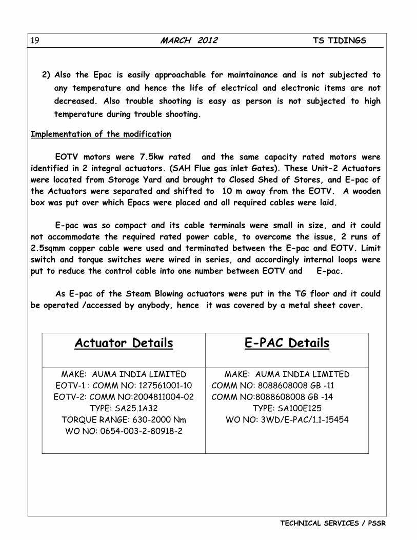
Implementation of the modification
EOTV motors were 7.5kw rated and the same capacity rated motors were identified in 2 integral actuators. (SAH Flue gas inlet Gates). These Unit-2 Actuators were located from Storage Yard and brought to Closed Shed of Stores, and E-pac of the Actuators were separated and shifted to 10 m away from the EOTV. A wooden box was put over which Epacs were placed and all required cables were laid.
E-pac was so compact and its cable terminals were small in size, and it could
not accommodate the required rated power cable, to overcome the issue, 2 runs of 2.5sqmm copper cable were used and terminated between the E-pac and EOTV. Limit switch and torque switches were wired in series, and accordingly internal loops were put to reduce the control cable into one number between EOTV and E-pac.
As E-pac of the Steam Blowing actuators were put in the TG floor and it could
be operated /accessed by anybody, hence it was covered by a metal sheet cover.
Actuator Details
E-PAC Details
MAKE: AUMA INDIA LIMITED EOTV-1 : COMM NO: 127561001-10 EOTV-2: COMM NO:2004811004-02
TYPE: SA25.1A32 TORQUE RANGE: 630-2000 Nm WO NO: 0654-003-2-80918-2
MAKE: AUMA INDIA LIMITED COMM NO: 8088608008 GB -11 COMM NO:8088608008 GB -14
TYPE: SA100E125 WO NO: 3WD/E-PAC/1.1-15454
20 MARCH 2012 TS TIDINGS
TECHNICAL SERVICES / PSSR
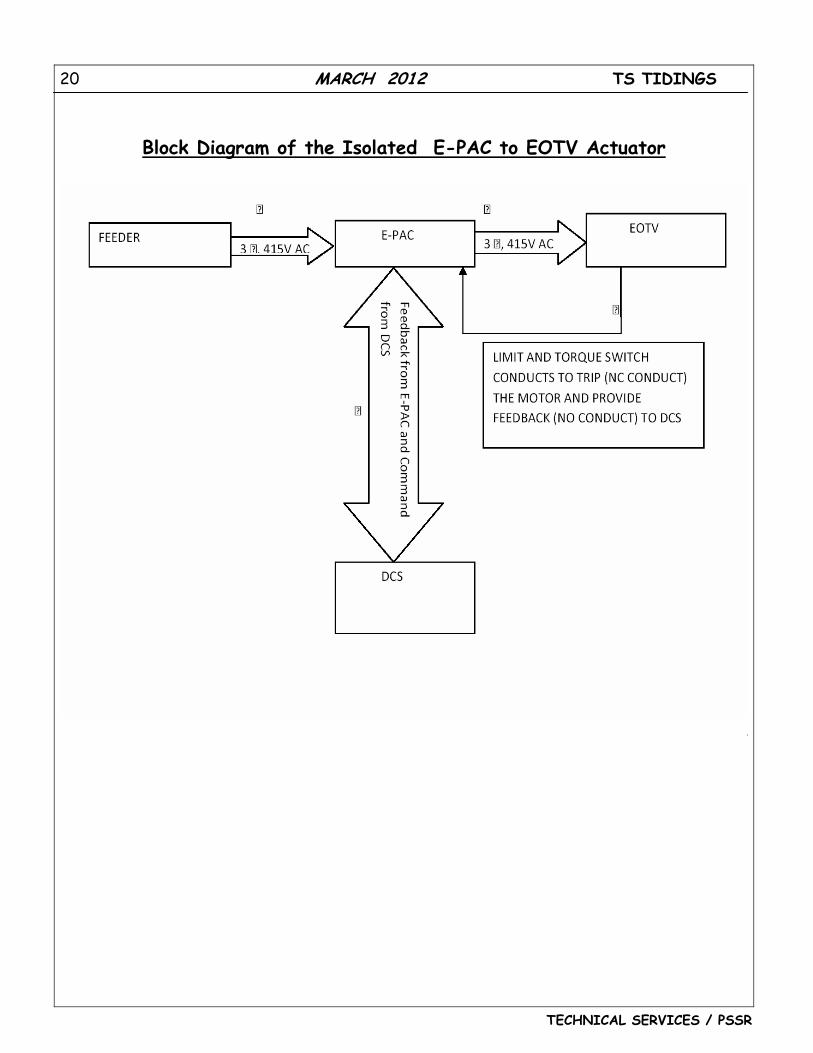
Block Diagram of the Isolated E-PAC to EOTV Actuator
21 MARCH 2012 TS TIDINGS
TECHNICAL SERVICES / PSSR
0
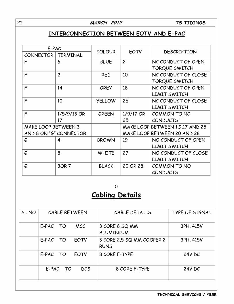
Cabling Details
SL NO CABLE BETWEEN CABLE DETAILS TYPE OF SIGNAL
� E-PAC TO MCC 3 CORE 6 SQ MM ALUMINIUM
3PH, 415V
� E-PAC TO EOTV 3 CORE 2.5 SQ MM COOPER 2 RUNS
3PH, 415V
� E-PAC TO EOTV 8 CORE F-TYPE 24V DC
� E-PAC TO DCS 8 CORE F-TYPE 24V DC
E-PAC CONNECTOR TERMINAL
COLOUR EOTV DESCRIPTION
F 6 BLUE 2 NC CONDUCT OF OPEN TORQUE SWITCH
F 2 RED 10 NC CONDUCT OF CLOSE TORQUE SWITCH
F 14 GREY 18 NC CONDUCT OF OPEN LIMIT SWITCH
F 10 YELLOW 26 NC CONDUCT OF CLOSE LIMIT SWITCH
F 1/5/9/13 OR 17
GREEN 1/9/17 OR 25
COMMON TO NC CONDUCTS
MAKE LOOP BETWEEN 3 AND 8 ON “G” CONNECTOR
MAKE LOOP BETWEEN 1,9,17 AND 25. MAKE LOOP BETWEEN 20 AND 28
G 4 BROWN 19 NO CONDUCT OF OPEN LIMIT SWITCH
G 8 WHITE 27 NO CONDUCT OF CLOSE LIMIT SWITCH
G 3OR 7 BLACK 20 OR 28 COMMON TO NO CONDUCTS
INTERCONNECTION BETWEEN EOTV AND E-PAC
22 MARCH 2012 TS TIDINGS
TECHNICAL SERVICES / PSSR
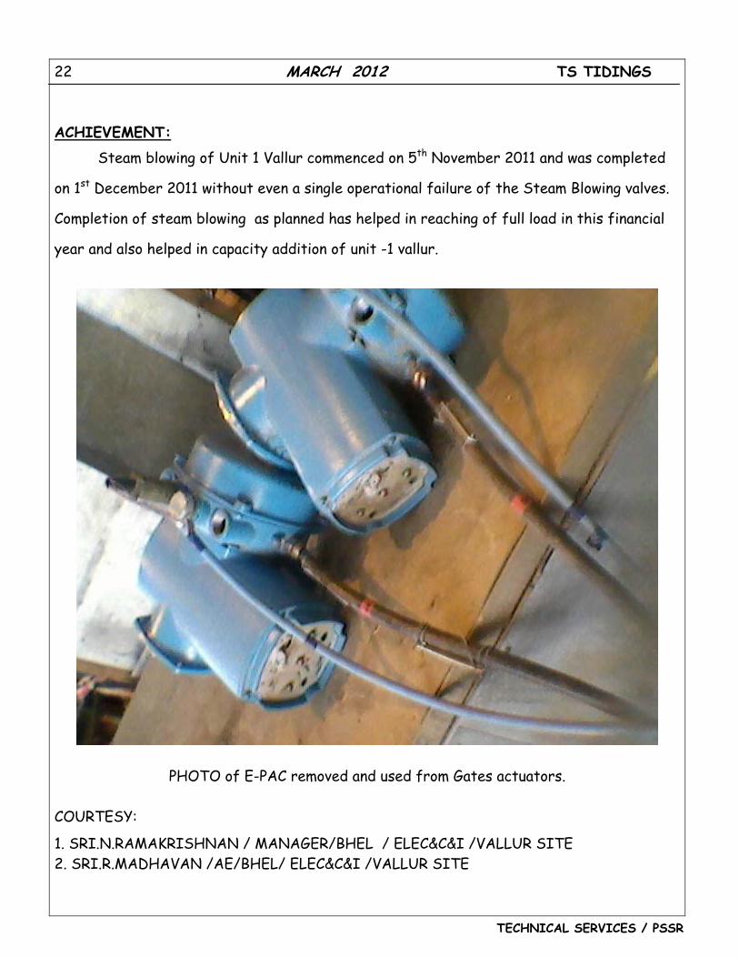
ACHIEVEMENT:
Steam blowing of Unit 1 Vallur commenced on 5th November 2011 and was completed
on 1st December 2011 without even a single operational failure of the Steam Blowing valves.
Completion of steam blowing as planned has helped in reaching of full load in this financial
year and also helped in capacity addition of unit -1 vallur.
PHOTO of E-PAC removed and used from Gates actuators. COURTESY:
1. SRI.N.RAMAKRISHNAN / MANAGER/BHEL / ELEC&C&I /VALLUR SITE 2. SRI.R.MADHAVAN /AE/BHEL/ ELEC&C&I /VALLUR SITE
23 MARCH 2012 TS TIDINGS
TECHNICAL SERVICES / PSSR
A Commissioning experience
(CONTINUATION OF Feb 2012)
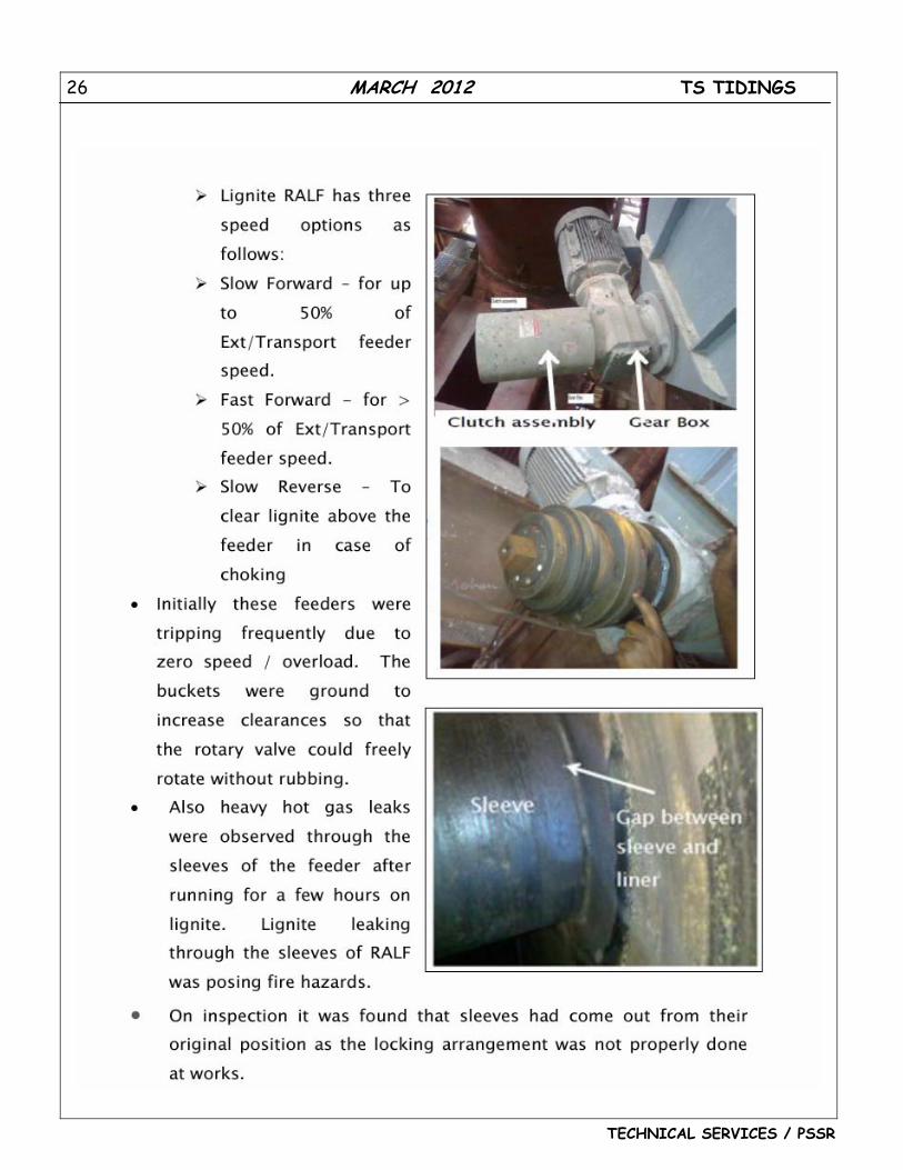
8. Air blower belt replacements.
There are about 21 blowers in each Boiler. • 2 Empty chamber blowers • 5 Seal pot Blowers • 5 Entry chamber Blowers • 5 Bundle chamber Blowers • 2 Purge and seal air Blowers • 2 Ash cooler Blowers
They provide , 1 fluidizing air to FBHEs bundle chambers 2 Fluidizing air for entry and empty chambers of FBHES, 3 Purge and seal air for equipments and systems as feeders, MFTs, Cyclones etc. 4 Ash cooler fluidization air
During the initial trial operation and commissioning of systems premature failures of air blower’s rubber belts caused startup delays. Alignments were rechecked and the primary reason for the failures was due to aging of rubber components. The belts were replaced and the performance is satisfactory now.
9. HT blowers Cooling Water (CW) lines introduction
Cooling water for HT blowers was not envisaged originally. However the gear box of the bundle chamber blowers required cooling water for their operation. The same was concurred by BHEL/Trichy and a separate CW header was laid from SGDMCW system.
10. Blowers zero speed switch adjustment Boiler was tripping frequently on FBHE blowers zero speed switch protection
.The speed switches were malfunctioning and tripping the blowers. On inspection it was found that zero speed switch mounting was not proper and speed sensor output
24 MARCH 2012 TS TIDINGS
TECHNICAL SERVICES / PSSR
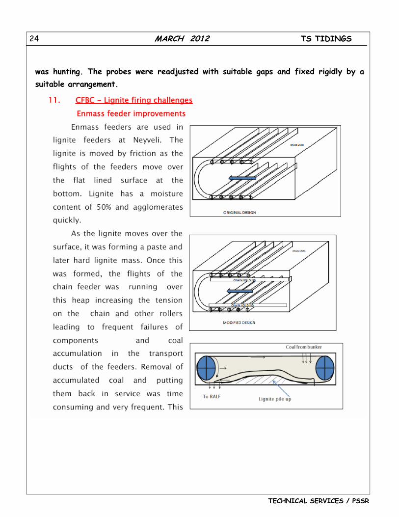
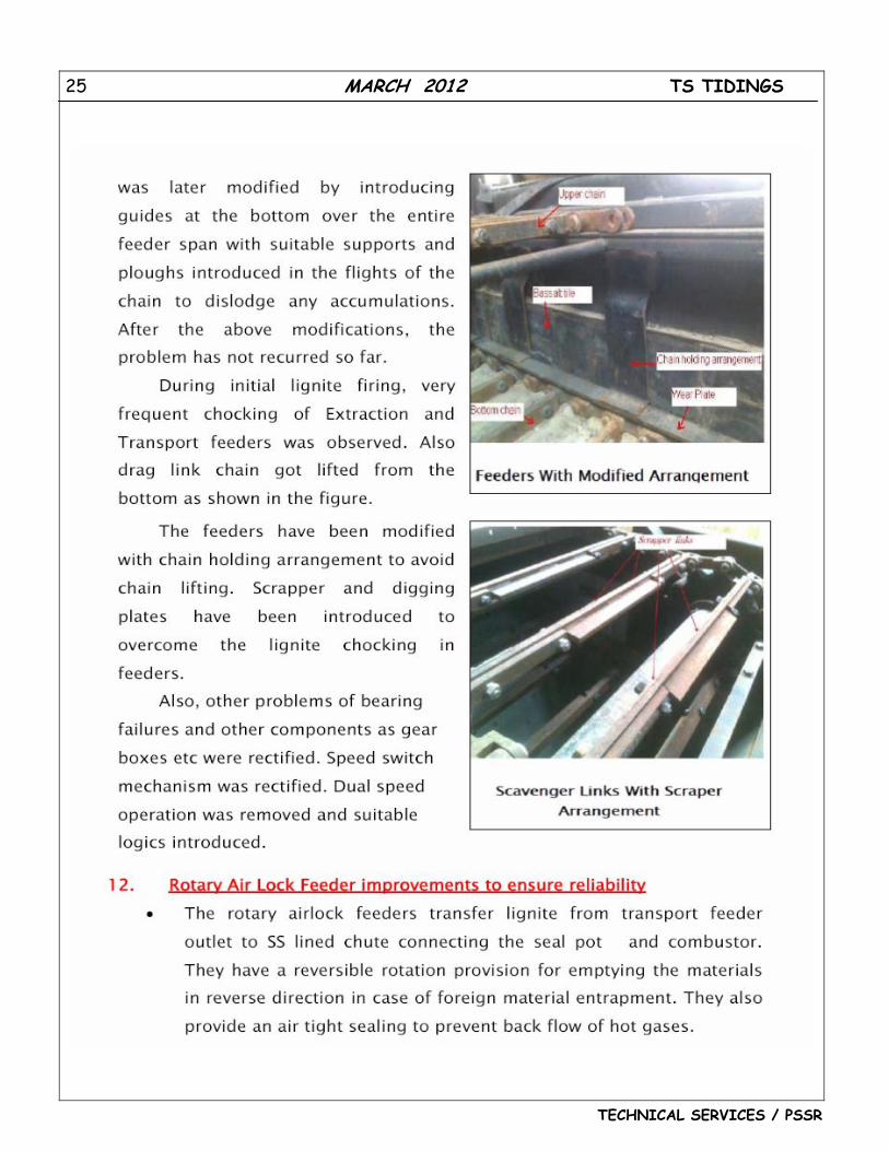
was hunting. The probes were readjusted with suitable gaps and fixed rigidly by a suitable arrangement.
25 MARCH 2012 TS TIDINGS
TECHNICAL SERVICES / PSSR
26 MARCH 2012 TS TIDINGS
TECHNICAL SERVICES / PSSR
27 MARCH 2012 TS TIDINGS
TECHNICAL SERVICES / PSSR
28 MARCH 2012 TS TIDINGS
TECHNICAL SERVICES / PSSR
29 MARCH 2012 TS TIDINGS
TECHNICAL SERVICES / PSSR
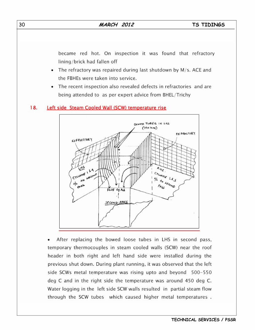
30 MARCH 2012 TS TIDINGS
TECHNICAL SERVICES / PSSR
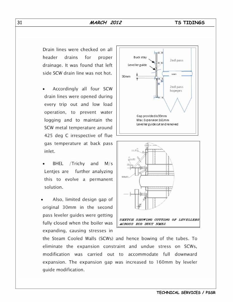
31 MARCH 2012 TS TIDINGS
TECHNICAL SERVICES / PSSR
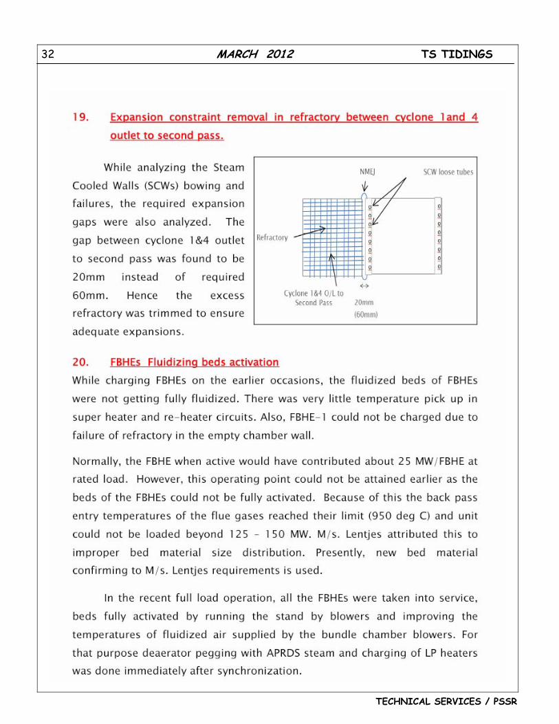
32 MARCH 2012 TS TIDINGS
TECHNICAL SERVICES / PSSR
33 MARCH 2012 TS TIDINGS
TECHNICAL SERVICES / PSSR
34 MARCH 2012 TS TIDINGS
TECHNICAL SERVICES / PSSR
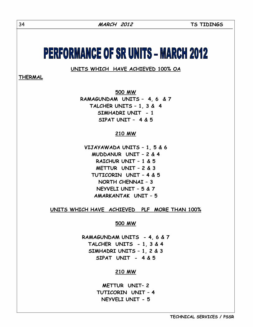
UNITS WHICH HAVE ACHIEVED 100% OA THERMAL
500 MW
RAMAGUNDAM UNITS – 4, 6 & 7 TALCHER UNITS – 1, 3 & 4
SIMHADRI UNIT - 1 SIPAT UNIT – 4 & 5
210 MW
VIJAYAWADA UNITS – 1, 5 & 6
MUDDANUR UNIT – 2 & 4 RAICHUR UNIT – 1 & 5 METTUR UNIT – 2 & 3
TUTICORIN UNIT – 4 & 5 NORTH CHENNAI – 3 NEYVELI UNIT – 5 & 7
AMARKANTAK UNIT – 5
UNITS WHICH HAVE ACHIEVED PLF MORE THAN 100%
500 MW
RAMAGUNDAM UNITS - 4, 6 & 7 TALCHER UNITS - 1, 3 & 4 SIMHADRI UNITS – 1, 2 & 3
SIPAT UNIT - 4 & 5
210 MW
METTUR UNIT– 2 TUTICORIN UNIT – 4
NEYVELI UNIT - 5
35 MARCH 2012 TS TIDINGS
TECHNICAL SERVICES / PSSR
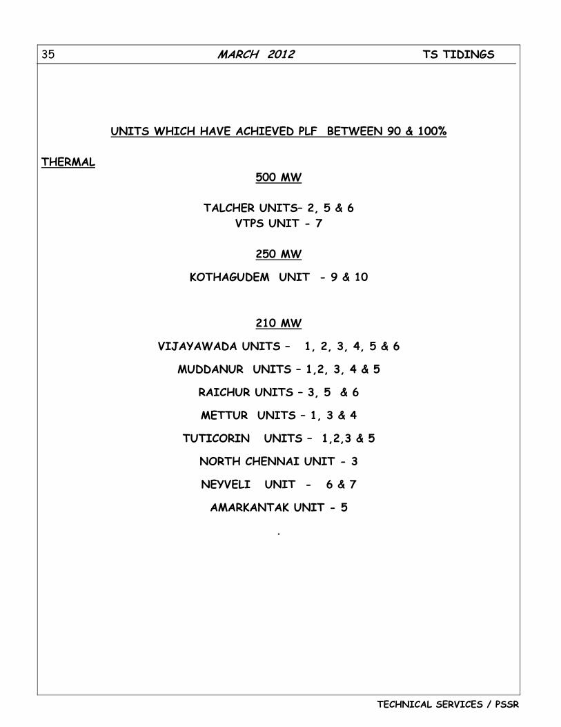
UNITS WHICH HAVE ACHIEVED PLF BETWEEN 90 & 100%
THERMAL 500 MW
TALCHER UNITS– 2, 5 & 6
VTPS UNIT - 7
250 MW
KOTHAGUDEM UNIT - 9 & 10
210 MW
VIJAYAWADA UNITS – 1, 2, 3, 4, 5 & 6
MUDDANUR UNITS – 1,2, 3, 4 & 5
RAICHUR UNITS – 3, 5 & 6
METTUR UNITS – 1, 3 & 4
TUTICORIN UNITS – 1,2,3 & 5
NORTH CHENNAI UNIT - 3
NEYVELI UNIT - 6 & 7
AMARKANTAK UNIT - 5
.
36 MARCH 2012 TS TIDINGS
TECHNICAL SERVICES / PSSR
0.00
20.00
40.00
60.00
80.00
100.00
120.00 2010‐11 2011‐12
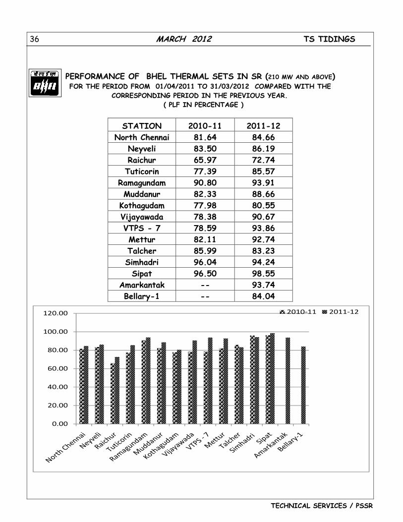
PERFORMANCE OF BHEL THERMAL SETS IN SR (210 MW AND ABOVE) FOR THE PERIOD FROM 01/04/2011 TO 31/03/2012 COMPARED WITH THE
CORRESPONDING PERIOD IN THE PREVIOUS YEAR. ( PLF IN PERCENTAGE )
STATION 2010-11 2011-12 North Chennai 81.64 84.66
Neyveli 83.50 86.19 Raichur 65.97 72.74 Tuticorin 77.39 85.57
Ramagundam 90.80 93.91 Muddanur 82.33 88.66
Kothagudam 77.98 80.55 Vijayawada 78.38 90.67 VTPS - 7 78.59 93.86 Mettur 82.11 92.74 Talcher 85.99 83.23 Simhadri 96.04 94.24 Sipat 96.50 98.55
Amarkantak -- 93.74 Bellary-1 -- 84.04


![Untitled-2 [ntpcnews.prosix.in]ntpcnews.prosix.in/writereaddata/Publication/PublicationPdf/245... · NTPC's main aim is to serve its customers by ... KAHALGAON KAHALGAON Dad ri Dadri](https://img.pdfslide.us/doc/110x75/5ab2f91d7f8b9ad9788db213/untitled-2-s-main-aim-is-to-serve-its-customers-by-kahalgaon-kahalgaon-dad.jpg)