Embed Size (px)
Citation preview
www.kaeser.com
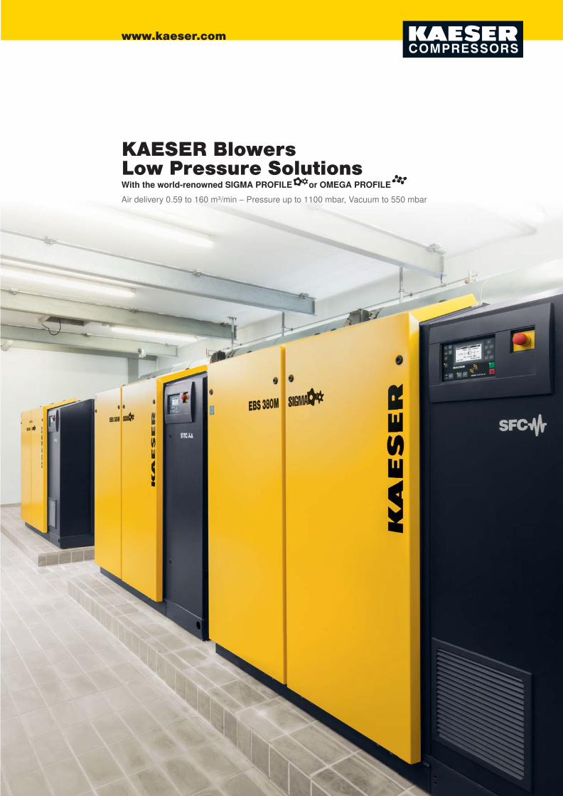
Air delivery 0.59 to 160 m³/min – Pressure up to 1100 mbar, Vacuum to 550 mbar
KAESER BlowersLow Pressure SolutionsWith the world-renowned SIGMA PROFILE or OMEGA PROFILE

2 3
KAESER blowers are used in a wide range of applications, such as effi cient and oil-free bulk material conveying, drinking and wastewater treatment (fi lter cleaning and aeration), liquid homogenisation and forced air systems for combustion equipment; the possibilities are almost endless – KAESER blowers are as versatile and varied as the applications that they are used for.
The world-renowned compressor and blower manufacturerEstablished by Carl Kaeser Sr. as a machine workshop in 1919, KAESER started on the road to becoming one of the world’s leading compressed air systems providers when the fi rst reciprocating compressor left the Coburg production line in 1948. The fi nal breakthrough came in the 1970s with the development of KAESER’s screw compressor featuring the energy-saving SIGMA PROFILE.
KAESER
Gera plant
In 1991, KAESER acquired the ‘Geraer Kompres-sorenwerke’, a company with a proud heritage of over 100 years of compressor and blower construction. Production of KAESER’s newly developed OMEGA rotary blowers began at the plant in 1993 and today these highly effi cient systems are exported, together with all necessary accessories and equipment, to every corner of the planet.
Contents
The world-renowned compressor and blower manufacturer .................. 02Contents ................................................................................................. 03
How a KAESER rotary blower works ...................................................... 04How a KAESER screw blower works ...................................................... 05
Screw blowers with the SIGMA PROFILE ..............................................06-07EBS – FBS series, SFC/STC version: Safe and effi cient .......................08-09
Rotary blowers with the OMEGA PROFILE ...........................................10-11BB – HB series, OFC/STC version: Complete blower systems ..............12-13
Rotary blower packages: BBC - HBC series ...........................................14-15Super-class blowers: HB-PI series .........................................................16-17
SIGMA CONTROL 2 controller ...............................................................18-19
Complete solutions from the systems provider .......................................20-21Advanced manufacture ...........................................................................22-23Special versions .....................................................................................24-25Accessories ............................................................................................26-27
Technical specifi cations ..........................................................................28-29
Covering an area of over 60,000 m², the Gera plant currently employs approximately 300 people and produces KAESER’s extensive range of rotary blow-ers, screw blowers and compressed air refrigeration dryers.
All companies in the international KAESER group are linked by the very latest information and network technology.
Water management
Food processing industry Chemicals industryGeneral industry
Beverageindustry
Bulk material conveyingTransportation Burner airsupply
Mining
Maritime applications
Fields of application

4 54
Pressure (P)
Volume (V)
Pressure (P)
Volume (V)
4
Intake air is captured Volume is reduced Expelled to pressure side Flow chamber completely evacuated
The pressure-volume diagram (P-V diagram) illustrates the energy, or compression work, expended for compres-sion on the basis of the area depicted in blue between points 1 to 4.
■ Thermodynamic energy consumption
Image: OMEGA block
The pressure-volume diagram (P-V diagram) illustrates the compression work in proportion to the energy expended on on the basis of the area depicted in blue between points 1 to 4.
The orange area shows the potential ener-gy savings when a screw blower is used in comparison to a conventional rotary blower (roots blower), as long as no over-compres-sion occurs.
■ Thermodynamic energy consumption■ Energy savings
Image: SIGMA blower airend
KAESER rotary blowersThe pressure build-up process – the images depict cross-sections of the fl ow chamber in the KAESER OMEGA rotary blower block.
How it works
KAESER screw blowersThe pressure build-up process – viewed from the pressure side onto the paired rotors in the SIGMA-B screw blower block, the fi gures depict the air volume enclosed in the screw chamber.
How it works
Oil-free isentropic compression process
As it is being conveyed through the screw compres-sion block, the entropy of the intake air remains virtually constant (isentropic). Compression takes place in the block, where the air volume is contin-uously reduced up until it reaches the block outlet and is pushed out against the pressure. The lower compression effort required to achieve the same air volume results in lower energy consumption. Screw blowers are ideally suited for applications with a near constant pressure demand and which require
long running periods, such as in fi lter bed aeration, fl otation etc.
The numbers correspond to the points in the pressure-volume diagram.
Intake and capture of atmospheric air.
Conveying toward pressure side to outlet.
Pressure increase through volume reduction.
Compressed air discharged.
Oil-free, isochoric compression process
As the intake air passes through the rotary blower’s fl ow chamber, its volume remains constant (isochoric process). Actual compression takes place outside of the blower block with the accumulation of the air mass taking place in the subsequent process. This “adaptive” compression always produces only the amount of pressure needed by the process. This makes rotary blowers particularly suitable for applications with a relatively high proportion of idling (e.g pneumatic conveying) and / or heavily fl uctuating pressure.
The numbers correspond to the points in the pressure-volume diagram.
Intake and capture of atmospheric air (left rotor).
Air is conveyed towards the pressure side; compression commences at the 120° rotation angle due to prior infl ux of already compressed air.
Compression in the conveying chamber ceases; discharge commences.
Conveyed air mass is discharged into the process.
Intake Pressure build up Air expelled Flow chamber completely evacuated

6 7
Screw blowersPure effi ciency − SIGMA PROFILE
Developed in the company’s in-house Research and Development centre, the KAESER screw blower airend with the world-renowned SIGMA PROFILE is up to 35 percent more effi cient than conventional airend designs. In addition to effi ciency, durability was also an important development goal. The use of high-tech bearings and no need for ancillary equipment further minimises energy consumption and also enhances reliability.
SIGMA PROFILE blower airend
The high-effi ciency blower airend combines a wide control range with near constant specifi c power. Equipped with SIGMA PROFILE rotors, they ensure maximum air delivery and keep power consumption to an absolute minimum.
Seamless system monitoring
Sensors for oil level and temperature monitoring are integrated into the blower airend. The oil chamber is designed to ensure dependable oil level measurement in all operating phases.
Durable bearings
All radial forces are borne by four robust cylinder roller bearings, which are rated to ensure long screw blower airend service life. The rollers are encased in high-tech cages for optimum lubrication at all speeds. Additional oil pressure lubrication is not necessary.
Dependable seals
The fi eld-proven sliding ring seal on the rotary transmis-sion drive shaft lead-through of the screw blower airend is maintenance-free and provides dependable sealing, even in hot and/or dusty environments.
EBS – FBS seriesAir delivery up to 67 m³/min, pressure diff erentialGauge pressure to 1100 mbar, Vacuum to 550 mbar

8 9
Check out the inside...
Simply use your smart phone to decode the link in the QR code and take a virtual fl ight to explore the inside of a KAESER screw blower (http://www.kaeser.com/ebs-fl ight).
Screw blowersEBS – FBS series, SFC/STC version
The combination of an advanced blower airend with the energy-saving SIGMA PROFILE, high-effi ciency mechanical and electrical components, minimal air-fl ow losses in the silencers, effi cient power transmission from the drive motor to the blow-er airend, as well as lowest possible electrical losses in the power switching module, ensures that KAESER screw blowers deliver optimum performance and effi ciency at all times.
SIGMA CONTROL 2
The SIGMA CONTROL 2 ensures effi cient blower control and system monitoring. Numerous interface options enable fast, dependable communication with centralised control systems via data bus, whilst the SD card slot makes data storage and updates a breeze. SFC/OFC machines feature a choice of various operating modes.
Comprehensive sensors
A wide range of sensors and switches for monitoring pressure, temperature, speed, oil level and fi lters ensures dependable blower operation and enables remote monitoring and visualisation of operational status.
Cool intake air
Process air and cooling air for the motor are drawn in separately from outside the enclosure. This boosts effi ciency and leads to a higher usable air mass fl ow rate for the same power consumption. The blowers can operate at ambient temperatures up to +45 °C.
Optimised specifi c power
The moderate maximum speed, the extra dense screw profi le and the near constant specifi c power across the wide variable speed control range all com-bine to achieve signifi cant energy savings throughout the entire operating curve.
Conventional speed control
Efficient KAESER speed control
Specific power(kW/m³/min)
Air flow (m³/min)

10 11
Rotary blowersPure reliability – OMEGA PROFILE
The special OMEGA Profi le in KAESER’s three-lobe rotary blowers makes these machines true masters of effi ciency. The long-term dependability and durability of these units is legendary. This is attributed to design features such as the use of straight cut timing gears, heavy-duty cylinder roller bearings and precisely balanced rotors.
BB – HB seriesAir delivery 1.5 to 74 m³/min, pressure diff erentialGauge pressure to 1000 mbar, Vacuum to 500 mbar
Durable OMEGA blower block
For pressures up to 1000 mbar(g), discharge temper-atures up to 160 °C, wide control range with frequen-cy-controlled operation, Q 2.5 rotor balancing for quieter operation, extended service life and minimal maintenance requirement.
Durable bearings
Heavy-duty cylinder roller bearings completely ab-sorb the continuously changing radial gas-forces that are exerted on the cylinders. As a result, they avoid the springing effect of self-aligning bearings and last up to ten times longer with the same loading.
Stable rotors
The combination of precise Q 2.5 rotor balancing and single-piece rotor machining ensures quiet, vibra-tion-free operation at all times. The rotor lobes are fi tted with integrated sealing strips to provide added protection for the blower block against dust particles and thermal stresses.
Precise synchronisation
High precision 5f 21 quality straight-cut timing gears have minimal fl ank clearance and a play major role in contributing to the block’s outstanding volumetric effi ciency. As the straight cut gearing is not subjected to continuously changing radial gas-forces, heavy-du-ty cylinder roller bearings can be used.

12 13
Rotary blowersComplete blower systemsBB-FB, OFC/STC version
KAESER’s COMPACT series turnkey rotary blowers with OMEGA PROFILE rotors provide more than dependable, effi cient performance. Delivered ready for immediate operation, these versatile units are equipped with star-delta starter (or frequency converter) and all necessary sensors are CE and EMC certifi ed. As a result, they save considerable costs associated with planning, installation, certifi cation, documentation and commissioning.
START CONTROL (STC)
The version with integrated Y-Δ-starter operates at constant speed and is equipped with a premium contactor, overload protection cut-out and phase loss monitoring. The SIGMA CONTROL 2 and a depend-able emergency stop system round out the package.
Plug and play
The turnkey blowers not only come complete with sensors, STC/OFC, SIGMA CONTROL 2 and emer-gency stop switch, but are also ready-fi lled with oil and are fully certifi ed. This signifi cantly reduces the work and costs required for planning, installation, certifi cation, documentation and commissioning.
Frequency control (OFC)
With OMEGA FREQUENCY CONTROL, the frequen-cy converter adjusts blower performance to match re-quired air demand. Everything is ready for immediate operation, since all programming and parametrisation is performed at the factory.
Complete system EMC certifi ed
To ensure seamless integration into any operation-al environment, the electromagnetic compatibility (EMC) of all components and of the complete pack-age has been tested and certifi ed in accordance with all applicable regulations.

14 15
IE3 energy-saving motors
All KAESER blower packages are equipped with dependable, premium effi ciency IE3 drive motors (IP55 protection, Insulation Class F). Their exception-al effi ciency boosts overall system performance.
Sensors
Various sensors and switches for monitoring pres-sure values, temperatures, speed, oil level and fi lters ensure dependable and effi cient blower operation and enable remote system monitoring.
Automatic belt tensioning
Irrespective of motor weight, the pivoted motor base with tensioning spring automatically ensures optimum belt tension and, as a result, transmission effi ciency. Consequently, this system also reduces servicing and maintenance costs.
Minimal pulsation and quiet operation
As pulsations from the conveying air can cause the connected pipework to generate noise; the sound-proofi ng on KAESER blowers is designed to minimise sound emissions from both the machine itself and from the conveying air. Moreover, highly effective discharge silencers have a wide frequency range to mitigate conveying air pulsation.
Rotary blower packages:BBC to HBC series
Effi cient, quiet, durable and versatile – whether in use to convey bulk materials or as heeling dampers on a container ship – KAESER blower packages are renowned throughout the world for their impressive performance no matter what the application.
BB – HB SeriesAir delivery 0.59 to 160 m³/min, pressure diff erentialGauge pressure to 1000 mbar, Vacuum to 500 mbar

16 17
IE3 energy-saving motors
All KAESER blower packages are equipped with dependable, premium effi ciency IE3 drive motors (IP55 protection, Insulation Class F). Medium-voltage motors can also be optionally used.
Frequency converter and Y-Δ starter
Special frequency converters and star-delta starters are also available for HB-PI series blowers. The OMEGA FREQUENCY CONTROL (OFC) enables in-fi nite blower speed adjustment and, with the addition of a pressure sensor, also allows pressure regulation.
Cooling air fl ow
Outstanding cooling performance is assured, as the drive motor is equipped with its own cooling air intake and ambient air is used for the process air. This results in maximum effi ciency and high capacity.
Dependable belt drive
The pivoted motor base and tensioning spring au-tomatically ensure optimum belt tension and, as a result, transmission effi ciency. Consequently, this sys-tem also reduces servicing and maintenance costs.
Super-class blowers:HB-PI series – Large and versatile
KAESER’s HB-PI series rotary blowers are the perfect choice for applications that require large air delivery volumes and maximum availability, such as in large water treatment plants, or in power generation stations. They are versatile, durable and dependable and, in combination with rapid-response KAESER Service, uninterrupted operation is guaranteed at all times.
HB-PI seriesAir delivery up to 160 m³/min,Gauge pressure to 1000 mbar, Vacuum to 500 mbar

Option: Plug-incommunication module
Profibus DP, Modbus TCP,ProfiNet
Blower system
SIGMA NETWORK KAESER CONNECT
The SIGMA CONTROL 2 internal controller and the SIGMA AIR MANAGER 4.0 master control system work in tandem to optimise the availability and effi ciency of compressed air stations. But there’s more: The various communications chan-nels enable seamless connection with centralised control systems, whilst their documentation functions make them indispensable tools for effective commer-cial energy management (and for certifi cation as per ISO 50001).
SIGMA AIR MANAGER 4.0
SIGMA CONTROL 2
System status
Graphs
Messages
IO display
User Management
Settings
Backup
Graphs
SIGMA CONTROL 2 1-default read => write Logout Contact/Service
1.0
0.5
0.0
-0.5
-1.03:50 pm 4:00 pm 4:10 pm
p1 / bar t1 / °C28
26
24
22
20
Time: 02/10/2014 04:11:40 pm
p1: 0.00 bar
t1: 23.3 °C
1.0
0.8
0.6
0.4
0.2
0.03:50 pm 4:00 pm 4:10 pm
p2 / bar t2 / °C90
85
80
75
70
65
60
55
p2: 0.40 bar
t2: 75.4 °C
Load
Idle
Off
3:50 pm 4:00 pm 4:10 pm
60
50
40
30
Operating state: Load
f: 59 Hz
f / Hz
Start: 02/10/2014 03:41:58 pm End: 02/10/2014 04:17:28 pm|< < < > > >|
18 19
The control centre
The control unit features an easy to read display and durable input keys, whilst the clear menu structure, together with 30 selectable languages, enables universal operation. Various operating modes are optionally available with SFC/OFC machines.
Stay connected
The Ethernet interface (10/100 MBbit/sec) allows users to call-up operational parameters on an Inter-net browser via the integrated web server. Optional communications modules: Modbus-RTU, Modbus/TCP, Profi bus DP-VO, Device-Net and Profi -Net IO.
Update and save
Software updates and operational parameters can be quickly uploaded and transferred via the convenient SD card slot. Service costs are therefore kept to an absolute minimum. Key operational data can also be stored on the SD card.
KAESER CONNECT
Simply connect a PC and the SIGMA CONTROL 2 (SC2) with the LAN and input the SC2 address and password in the browser. Once this is done, machine status, operating data, alarm messages, as well as graphical representation of pressure, temperature and speed can be viewed in real time.
Intelligence insideSIGMA CONTROL 2 blower controller
Using a range of sensors, the internal SIGMA CONTROL 2 blower controller monitors and controls all relevant machine and process parameters essential to reliable and effi cient blower system operation. Available remote monitoring and control fur-ther enhance blower availability and effi ciency. Versatile communication modules also enable SIGMA CONTROL 2 equipped blower packages to connect to master control systems, such as the SIGMA AIR MANAGER, and / or other centralised control systems via data bus.
Integrated Industry – Join the network
With the SIGMA CONTROL 2 and SIGMA AIR MANAGER 4.0, all blower stations can be seamlessly integrated into Industry 4.0 environments to enable continuous system optimisation through analysis of operating data and to provide demand-oriented pre-ventative maintenance and servicing (Predictive Maintenance) through remote diagnostics.

20 21
Precise demand analysis (ADA 2)
Using precise Air Demand Analysis (ADA) and the KAESER Energy Saving System (KESS), KAESER’s experts are able to plan and design a system that is specially tailored to meet all of your blower air requirements and which will keep your air costs to an absolute minimum.
Fast, worldwide service
Since even the highest quality of machines requires regular maintenance, KAESER AIR SERVICE, with its specially trained service technicians and ad-vanced logistics systems, ensures continuous blower air availability and reliable delivery of genuine KAESER spare parts throughout the world.
Optimum climate control
A holistic approach to the blower station also includes climate control. With expertise and com-ponents for optimum blower station climate control, KAESER blower systems always have the right amount of cool intake air available and therefore save energy through enhanced effi ciency.
Detailed and expert planning
KAESER’s experts meticulously plan and design a system that is tailored to meet the customer’s specifi c blower air needs. Needless to say, this includes room ventilation and pipework, thereby ensuring peace of mind for users and project planners.
One-stop shopComplete solutions from the systems provider
A business’s blower air supply is far more than the sum of the necessary equipment and components, and by that token, as a comprehensive compressed air and blower air systems provider, KAESER KOMPRESSOREN provides far more than just machines. From detailed demand analysis and seamless integration of the blower station into the business environment, to life-long availability assurance through rapid-response KAESER AIR SERVICE, KAESER KOMPRESSOREN has all of your air needs covered

22 23
Measurementand inspection
To maintain the very best in product quality, we meticulously inspect and measure every block casing and rotor to ensure that it is manufactured to within the specifi ed tolerances.
Case manufacture
Just like the rotors, the cas-ing for every KAESER rotary blower block is machined using advanced climate-con-trolled CNC machining cen-tres to ensure consistently high product quality.
Flexible production
The very latest production techniques and processes at KAESER’s Gera plant ensure exceptional product quality and enable custom-er-specifi c requirements to be met with minimal lead time.
Final inspection
All adjustments such as belt tensioning and alignment are carried out ex-works prior to delivery. Moreover, every blower block is delivered ready-fi lled with oil and all valves are adjusted. All data are documented.
Powder coating
The enclosures receive their quality surface coat-ing in an environmentally compatible 180 °C powder coating process. The result is a highly resilient scratch- and corrosion-re-sistant fi nish that provides exceptional protection even under the toughest conditions.
Rotor and blockmachining
Both rotors and blocks are precision machined to micron accuracy, so that the resulting surface quality makes wear-susceptible coatings used for sealing superfl uous.
Advanced manufactureFor quality and performance
Manufacture to the most exacting tolerances ensures exceptional quality of mechanical and electrical components and en-sures smooth interplay between all individual parts and systems. All components are precisely matched with one another are meticulously documented. The enables traceability and guarantees trouble-free spare parts supply at any time.

24 25
WVC series – Fine vacuum
WVC series machines with a volumetric fl ow rate of up to 6,800 m³/hr are suited for fi ne vacuum appli-cations such as in pumping stations with a booster pump to increase their volumetric fl ow rate.
OMEGA B/PB – Corrosion resistant
Rotors and block casings made from cast chromi-um-nickel alloy and with special internal block-sealing are available for processes such as the compression of water vapour in vacuum distillation for the concen-tration of aqueous media, for example.
OMEGA PN: Nitrogen conveying
These blowers are ideal for pneumatic conveying of bulk materials under nitrogen atmosphere condi-tions, where leakages of any kind need to be kept to an absolute minimum. PN series blowers are also available with wear-free slide ring sealing of the drive shaft rotary feedthrough. Complete systems with OMEGA PN blocks are available for nitrogen convey-ing applications.
OMEGA PV – Low vacuum
With a suction capacity of up to 120 m³/min for low vacuum applications and a maximum of 900 mbar differential pressure, the OMEGA PV blower block is exceptionally robust. Able to produce both vacuum and pressure via selective switching of the process lines, these blowers are particularly well suited for tanker lorries. The block is cooled with ambient air via the pre-inlet cooling ports.
Special versionsFor specialised applications
Whether used on a tanker lorry as a mobile unloading station, or for compression and / or conveying of media ranging from nitrogen to steam, KAESER blowers are always dependable and effi cient OEM components.

26 27
AccessoriesFor a wide range of applicationsA wide range of applications often require a specifi c air quality: For example, some materials are sensitive to heat, whilst others may clump if humidity is too high. Another potential problem is contamination of the blower air by particles in the ambi-ent air. As one of the world’s leading system providers, KAESER has a wide range of coolers, dryers and fi lters designed to cope with these and many other instances. Decades of experience in air generation and treatment also enable KAESER’s experts to precisely match each individual component to achieve optimum system performance. Furthermore, the SIGMA AIR MANAGER enables the fl ow rate of every blower station to be specifi cally tailored to meet actual air demand, thereby ensuring maximum energy effi ciency.
Heat exchanger
Easily integrated into pro-cess control systems, the heat exchanger enables exceptional process-air cooling even at high ambi-ent temperatures. The hot water produced as a result of this process can be used for other purposes.
Drying
KAESER’s intake air desiccant dryers reduce the pressure dewpoint of process air with minimum differential pressure, thereby preventing con-densate formation.
Outdoor installation
COMPACT blowers are often installed outdoors in many water clarifi ca-tion plants. These blower packages come equipped with rainproof stainless steel covers and premium powder-coated enclosures for effective protection against the elements.
The operating environment
Carefully matched com-ponents, such as weather protection screens, fans, inlet / discharge silenc-ers and appropriate air ducting, help to ensure and maintain optimum operating conditions in the machine room at all times.
Cooling
At an ambient tempera-ture of 20 °C, the highly effi cient ACA type after-cooler is able to reduce temperature to 30 °C whilst perfectly maintaining pressure.
Co-ordination
Depending on the model, the SIGMA AIR MANAGER control system is able to co-ordinate operation of 4, 8 or 16 blowers within a blower installation and en-sures even load distribution between the units.

28 29
Modell Überdruck Unterdruck max. Motor-nenn-
leistung
Rohr-anschluss
Abmessungen mit Schaltschrank und Schallhaube
B x T x H
Massemax.
max. Druck-
diff erenz
max. Liefer-
menge *max.
Druckdiff erenzmax. Saug-
vermögen
mbar (ü) m³/min mbar (vac) m³/min kW DN mm kg
BB 69 C 1,000 5.9 500 5.9 15 65 1,210 x 960 x 1,200 455
BB 89 C 1,000 8.2 500 8.3 15 65 1,210 x 960 x 1,200 461
CB 111 C 800 8.8 400 8.9 18.5 80 1,530 x 1,150 x 1,290 583
CB 131 C 1,000 12.3 500 12.4 30 80 1,530 x 1,150 x 1,290 642
DB 166 C 1,000 15.6 500 15.7 37 100 1,530 x 1,150 x 1,290 802
DB 236 C 1,000 22.1 500 22.3 45 100 1,530 x 1,150 x 1,290 822
EB 291 C 1,000 28.6 500 28.8 75 150 1,935 x 1,600 x 1,700 1,561
EB 421 C 1,000 40.1 500 40.4 75 150 1,935 x 1,600 x 1,700 1,606
FB 441 C 1,000 41.3 500 41.6 90 200 2,230 x 1,920 x 1,910 2,326
FB 621 C 1,000 58.5 500 58.9 132 200 2,230 x 1,920 x 1,910 2,839
FB 791 C 800 71.3 500 71.8 110 250 2,230 x 1,920 x 2,090 2,541
Modell Überdruck Unterdruck Rohr-anschluss
Abmessungen mit Schaltschrank und Schallhaube
B x T x H
Massemax.
max. Druck-
diff erenz
max. Liefer-
menge *
max. Motornenn-
leistung
max. Druck-
diff erenz
max. Saug-
vermögen
max. Motornenn-
leistung
mbar (ü) m³/min kW mbar (vac) m³/min kW DN mm kg
EB 380S L 650 38 45 – – –150 1,940 x 1,600 x 1,700
1,400
EB 380S M 1,100 37 75 550 37 37 1,600
FB 660S L 650 67 90 – – –200 2,250 x 1,950 x 1,900
1,850
FB 660S M 1,100 66 110 – – – 2,200
Modell Überdruck Unterdruck max. Motor-nenn-
leistung
Rohr-anschluss
Abmessungen ohne Schalldämm-
haubeB x T x H
Massemax.
Abmessungen mit Schall-
dämmhaubeB x T x H
Massemax.
max. Druck-
diff erenz
max. Liefer-
menge *
max. Druck-
diff erenz
max. Saug-
vermögen
mbar (ü) m³/min mbar (vac) m³/min kW DN mm kg mm kg
BB 52 C
1,000
4.7
500
4.7 7,5 50 785 x 635 x 940 140 800 x 790 x 1,120 210
BB 69 C 5.9 5.9 11 65 890 x 660 x 960 195 960 x 780 x 1,200 325
BB 89 C 8.2 8.3 15 65 890 x 660 x 960 201 960 x 780 x 1,200 331
CB 111 C 800 8.8 400 8.9 18 80 855 x 1,010 x 1,290 263 990 x 1,160 x 1,290 443
CB 131 C 1,000 12.3 500 12.4 30 80 855 x 1,010 x 1,290 302 990 x 1,160 x 1,290 482
DB 166 C1,000
15.6500
15.7 37 100 990 x 1,070 x 1,120 432 1,110 x 1,160 x 1,290 632
DB 236 C 21.1 22.3 45 100 990 x 1,070 x 1,120 482 1,110 x 1,160 x 1,290 682
EB 291 C1,000
28.6500
28.8 75 150 1,240 x 1,370 x 1,510 921 1,420 x 1,600 x 1,659 1,261
EB 421 C 40.1 40.4 75 150 1,240 x 1,370 x 1,510 966 1,420 x 1,600 x 1,659 1,306
FB 441 C1,000
41.3500
41.6 90 200 1,790 x 1,450 x 1,750 1,450 1,920 x 1,620 x 1,910 1,960
FB 621 C 58.5 58.9 132 200 1,790 x 1,450 x 1,750 1,865 1,920 x 1,620 x 1,910 2,375
FB 791 C 800 71.3 450 71.8 110 250 1,870 x 1,450 x 1,900 1,717 1,920 x 1,620 x 2,090 2,247
HB 950 C1,000
93.1 500
91.65 200 250 1,700 x 1,700 x 1,950 3,005 2,170 x 1,864 x 2,110 3,805
HB 1300 PI 125 122.93 250 300 2,710 x 1,600 x 2,350 3,465 3,205 x 2,150 x 2,610 4,285
HB 1600 PI 800 156 450 153.27 250 300 2,710 x 1,600 x 2,350 3,625 3,205 x 2,150 x 2,610 4,445
Model Gauge pressure Vacuum Max. ratedmotor power
Pipeconnection
Dimensions with control cabinet and sound enclosure
W x D x H
Weightmax.
Max.diff erentialpressure
Max.air
delivery *
Max.pressure
diff erential
Max. intake
capacity
mbar (g) m³/min mbar (vac) m³/min kW DN mm kg
Model Gauge pressure Vacuum Max. rated motor power
Pipeconnection
Dimensionswithout sound
enclosureW x D x H
Weightmax.
Dimensionswith soundenclosureW x D x H
Weightmax.
Max.diff erentialpressure
Max.air
delivery *
Max.diff erentialpressure
Max. intake
capacity
mbar (g) m³/min mbar (vac) m³/min kW DN mm kg mm kg
Model Gauge pressure Vacuum Pipe con-nection
Dimensions with control cabinet
and sound enclosureW x D x H
Weightmax.
Max.diff erentialpressure
Max.air
delivery *
Max.rated motor
power
Max.diff erentialpressure
Max. intake
capacity
Max.rated motor
power
mbar (g) m³/min kW mbar (vac) m³/min kW DN mm kg
Screw blowers – EBS-FBS STC/SFC seriesUp to 110 kW, ready-to-run with integrated electrical equipment
*) Performance data as per ISO 1217, Appendix C for STC version, Appendix E for SFC version
Blower packages – BBC-HBPI seriesUp to 250 kW
*) Performance data as per ISO 1217, Appendix C for STC version, Appendix E for OFC version
*) Performance data as per ISO 1217 Appendix C
Compact blowers – BBC-FBC STC/OFC seriesUp to 132 kW, ready-to-run with integrated electrical equipment

30 31

KAESER – The world is our home
KAESER KOMPRESSOREN SEP.O. Box 2143 – 96410 Coburg – GERMANY – Tel +49 9561 640-0 – Fax +49 9561 640-130e-mail: [email protected] – www.kaeser.com
As one of the world’s largest compressed air systems providers and compressor manufacturers, KAESER KOMPRESSOREN is represented throughout the world by a comprehensive network of branches, subsidiary companies and authorised partners in over 100 countries.
With innovative products and services, KAESER KOMPRESSOREN’s experienced consultants and engineers help customers to enhance their competitive edge by working in close partnership to develop progressive system concepts that continuously push the boundaries of performance and compressed air effi ciency. Moreover, the decades of knowledge and expertise from this industry-leading system provider are made available to each and every customer via the KAESER group’s global computer network.
These advantages, coupled with KAESER’s worldwide service organisation, ensure that all products operate at the peak of their performance at all times and provide maximum availability.
www.kaeser.com
P-90
0ED
Spe
cifi ca
tions
are
sub
ject
to c
hang
e wi
thou
t not
ice
.16/
16


![B38 Series Commercial & Light Industrial Product Details[1]scno Inlet Pressure Loading (25 12' wc (30 mbar 16" 140 mbar (45 mbar 69 'roar 38) Chapae in outlet tar a PSIG inlet change](https://img.pdfslide.us/doc/110x75/5ffdd182e8e777359b25be1a/b38-series-commercial-light-industrial-product-details1-scno-inlet-pressure.jpg)


![EVR Series - Pressure Control Solutions... 5 PRESSURE RANGES 0 to -29.5 inHg (12 to 760 torr) [0 to -980 mbar] 0 - 10 in Hg [0 to -340 mbar) *Pressure ranges as low as 0 to -2 in H2O](https://img.pdfslide.us/doc/110x75/5f37d5b2d4cec719b70d5ee7/evr-series-pressure-control-solutions-5-pressure-ranges-0-to-295-inhg-12.jpg)