Embed Size (px)
Citation preview

Mot
herb
oard
K8N-E
User Guide

ii
Checklist
Copyright © 2005 ASUSTeK COMPUTER INC. All Rights Reserved.No part of this manual, including the products and software described in it, may bereproduced, transmitted, transcribed, stored in a retrieval system, or translated into anylanguage in any form or by any means, except documentation kept by the purchaser forbackup purposes, without the express written permission of ASUSTeK COMPUTER INC.(“ASUS”).
Product warranty or service will not be extended if: (1) the product is repaired, modified oraltered, unless such repair, modification of alteration is authorized in writing by ASUS; or (2)the serial number of the product is defaced or missing.
ASUS PROVIDES THIS MANUAL “AS IS” WITHOUT WARRANTY OF ANY KIND, EITHEREXPRESS OR IMPLIED, INCLUDING BUT NOT LIMITED TO THE IMPLIED WARRANTIESOR CONDITIONS OF MERCHANTABILITY OR FITNESS FOR A PARTICULAR PURPOSE.IN NO EVENT SHALL ASUS, ITS DIRECTORS, OFFICERS, EMPLOYEES OR AGENTS BELIABLE FOR ANY INDIRECT, SPECIAL, INCIDENTAL, OR CONSEQUENTIAL DAMAGES(INCLUDING DAMAGES FOR LOSS OF PROFITS, LOSS OF BUSINESS, LOSS OF USEOR DATA, INTERRUPTION OF BUSINESS AND THE LIKE), EVEN IF ASUS HAS BEENADVISED OF THE POSSIBILITY OF SUCH DAMAGES ARISING FROM ANY DEFECT ORERROR IN THIS MANUAL OR PRODUCT.
SPECIFICATIONS AND INFORMATION CONTAINED IN THIS MANUAL ARE FURNISHEDFOR INFORMATIONAL USE ONLY, AND ARE SUBJECT TO CHANGE AT ANY TIMEWITHOUT NOTICE, AND SHOULD NOT BE CONSTRUED AS A COMMITMENT BY ASUS.ASUS ASSUMES NO RESPONSIBILITY OR LIABILITY FOR ANY ERRORS ORINACCURACIES THAT MAY APPEAR IN THIS MANUAL, INCLUDING THE PRODUCTSAND SOFTWARE DESCRIBED IN IT.
Products and corporate names appearing in this manual may or may not be registeredtrademarks or copyrights of their respective companies, and are used only for identification orexplanation and to the owners’ benefit, without intent to infringe.
E2164
First Edition
July 2005

iii
Fea
ture
s
ContentsNotices ........................................................................................... vi
Safety information ......................................................................... vii
About this guide ............................................................................ viiiConventions used in this guide ........................................... viiiTypography .......................................................................... viii
K8N-E specifications summary ...................................................... ix
Chapter 1: Product introduction1.1 Welcome! ........................................................................... 1-2
1.2 Package contents ............................................................... 1-2
1.3 Special features .................................................................. 1-31.3.1 Product Highlights .................................................. 1-31.3.2 Unique ASUS features ........................................... 1-4
1.4 Before you proceed ............................................................ 1-5
1.5 Motherboard overview ........................................................ 1-61.5.1 Motherboard layout ................................................ 1-61.5.2 Placement direction ............................................... 1-71.5.3 Screw holes ........................................................... 1-7
1.6 Central Processing Unit (CPU) ........................................... 1-81.6.1 Overview ................................................................ 1-81.6.2 Installing the CPU .................................................. 1-9
1.7 System memory ............................................................... 1-101.7.1 DIMM sockets location ......................................... 1-101.7.2 Memory configurations ........................................ 1-101.7.3 Installing a DIMM ................................................. 1-12
1.8 Expansion slots ................................................................ 1-121.8.1 Standard interrupt assignments ........................... 1-121.8.2 IRQ assignments for this motherboard ................ 1-131.8.3 PCI slots .............................................................. 1-131.8.4 AGP slot ............................................................... 1-14
1.9 Jumpers ............................................................................ 1-15
1.10 Connectors ....................................................................... 1-171.10.1 Rear panel connectors ......................................... 1-171.10.2 Internal connectors .............................................. 1-18

iv
Safeguards
ContentsChapter 2: BIOS Information
2.1 Managing and updating your BIOS .................................... 2-22.1.1 Creating a bootable floppy disk ............................. 2-22.1.2 Using AFUDOS to update the BIOS ...................... 2-32.1.3 Using AFUDOS to copy BIOS from PC ................. 2-42.1.4 Using ASUS EZ Flash to update the BIOS ............ 2-52.1.5 Recovering the BIOS with CrashFree BIOS 2 ....... 2-6
2.2 BIOS Setup program .......................................................... 2-82.2.1 BIOS menu screen ................................................ 2-92.2.2 Menu bar ................................................................ 2-92.2.3 Navigation keys ..................................................... 2-92.2.4 Menu items .......................................................... 2-102.2.5 Sub-menu items ................................................... 2-102.2.6 Configuration fields .............................................. 2-102.2.7 Pop-up window .................................................... 2-102.2.8 Scroll bar .............................................................. 2-102.2.9 General help ........................................................ 2-10
2.3 Main menu .........................................................................2-112.3.1 System Time .........................................................2-112.3.2 System Date .........................................................2-112.3.3 Legacy Diskette A .................................................2-112.3.4 Primary and Secondary IDE Master/Slave .......... 2-122.3.5 System Information .............................................. 2-13
2.4 Advanced menu ............................................................... 2-142.4.1 JumperFree Configuration ................................... 2-142.4.3 CPU Configuration ............................................... 2-162.4.4 Chipset ................................................................. 2-172.4.5 Onboard Devices Configuration ........................... 2-212.4.6 PCI PnP ............................................................... 2-22
2.5 Power menu ..................................................................... 2-242.5.1 ACPI Suspend Mode ........................................... 2-242.5.2 Repost Video on S3 Resume............................... 2-242.5.3 ACPI 2.0 Support ................................................. 2-242.5.4 ACPI APIC Support .............................................. 2-242.5.5 APM Configuration ............................................... 2-252.5.6 Hardware Monitor ................................................ 2-26
2.6 Boot menu ........................................................................ 2-272.6.1 Boot Device Priority ............................................. 2-27

v
2.6.2 Hard Disk Drives .................................................. 2-282.6.3 Boot Settings Configuration ................................. 2-282.6.4 Security ................................................................ 2-29
2.7 Exit menu ......................................................................... 2-32
Chapter 3: Software support3.1 Install an operating system................................................. 3-2
3.2 Support CD information ...................................................... 3-23.2.1 Running the support CD ........................................ 3-23.2.2 Drivers menu ......................................................... 3-33.2.3 Utilities menu ......................................................... 3-43.2.4 Manual menu ......................................................... 3-53.2.5 ASUS Contact Information ..................................... 3-5
3.3 Cool ‘n’ Quiet!™ Technology .............................................. 3-6
Contents

vi
Notices
Federal Communications Commission Statement
This device complies with Part 15 of the FCC Rules. Operation is subject tothe following two conditions:• This device may not cause harmful interference, and
• This device must accept any interference received including interference thatmay cause undesired operation.
Canadian Department of Communications Statement
This digital apparatus does not exceed the Class B limits for radio noiseemissions from digital apparatus set out in the Radio InterferenceRegulations of the Canadian Department of Communications.
This class B digital apparatus complies with Canadian ICES-003.
The use of shielded cables for connection of the monitor to the graphics card isrequired to assure compliance with FCC regulations. Changes or modificationsto this unit not expressly approved by the party responsible for compliancecould void the user’s authority to operate this equipment.
Where to find more informationRefer to the following sources for additional information and for product andsoftware updates.
1. ASUS Websites
The ASUS website provides updated information on ASUS hardware andsoftware products. The ASUS websites are listed in the ASUS ContactInformation on the inside front cover.
2. Optional Documentation
Your product package may include optional documentation, such as warrantyflyers, that may have been added by your dealer. These documents are notpart of the standard package.

vii
Safety information
Electrical safety• To prevent electrical shock hazard, disconnect the power cable from the
electrical outlet before relocating the system.
• When adding or removing devices to or from the system, ensure that the powercables for the devices are unplugged before the signal cables are connected. Ifpossible, disconnect all power cables from the existing system before you add adevice.
• Before connecting or removing signal cables from the motherboard, ensure thatall power cables are unplugged.
• Seek professional assistance before using an adpater or extension cord. Thesedevices could interrupt the grounding circuit.
• Make sure that your power supply is set to the correct voltage in your area. If youare not sure about the voltage of the electrical outlet you are using, contact yourlocal power company.
• If the power supply is broken, do not try to fix it by yourself. Contact a qualifiedservice technician or your retailer.
Operation safety• Before installing the motherboard and adding devices on it, carefully read all the
manuals that came with the package.
• Before using the product, make sure all cables are correctly connected and thepower cables are not damaged. If you detect any damage, contact your dealerimmediately.
• To avoid short circuits, keep paper clips, screws, and staples away fromconnectors, slots, sockets and circuitry.
• Avoid dust, humidity, and temperature extremes. Do not place the product in anyarea where it may become wet.
• Place the product on a stable surface.
• If you encounter technical problems with the product, contact a qualified servicetechnician or your retailer.

viii
About this guide
Conventions used in this guideTo make sure that you perform certain tasks properly, take note of the followingsymbols used throughout this manual.
WARNING: Information to prevent injury to yourself when trying tocomplete a task.
CAUTION: Information to prevent damage to the components whentrying to complete a task.
IMPORTANT: Information that you MUST follow to complete a task.
NOTE: Tips and additional information to aid in completing a task.
TypographyBold text Indicates a menu or an item to select
Italics Used to emphasize a word or a phrase
<Key> Keys enclosed in the less-than and greater-than sign means that you must press theenclosed keyExample: <Enter> means that you must pressthe Enter or Return key
<Key1+Key2+Key3> If you must press two or more keyssimultaneously, the key names are linked witha plus sign (+)Example: <Ctrl+Alt+D>
Command Means that you must type the commandexactly as shown, then supply the requireditem or value enclosed in bracketsExample: At the DOS prompt, type thecommand line: afudos /iK8NE.ROM

ix
K8N-E specifications summary
(continued on the next page)
Socket 754 for AMD Athlon™ 64 and AMD Sempron™ CPUsSupports AMD 64 architecture that enables simultaneous
32-bit and 64-bit computingSupports AMD Cool ‘n’ Quiet!™ Technology
NVIDIA® nForce™ 3 250Gb
1600 MT/s
3 x 184-pin DDR DIMM sockets for up to 3GB unbufferedECC and non-ECC PC3200/PC2700/PC2100/PC1600SDRAM memory
1 x AGP 8X/4X5 x PCI
NVIDIA® nForce™ 3 250Gb supports:- 2 x Ultra ATA 133 connector- 2 x Serial ATA connectors with RAID 0, RAID 1, and JBOD sets
Marvell Gbit LAN PHY 88E1111
Realtek® ALC850 6-channel CODECAudio Sensing and Enumeration TechnologyS/PDIF out support
CPU, Memory and AGP voltage adjustableSFS (Stepless Frequency Selection) from 200 MHz up to
300 MHz at 1 MHz incrementAdjustable FSB/DDR ratio. Fixed AGP/PCI frequencies
Maximum of eight (8) USB 2.0 ports
ASUS MyLogo2™ASUS EZ FlashASUS JumperFreeASUS C.P.R. (CPU Parameter Recall)
1 x Parallel port1 x Serial port1 x PS/2 keyboard port1 x PS/2 mouse port4 x USB 2.0 ports1 x RJ-45 port1 x 6-channel audio I/O ports1 x Coaxial S/PDIF Out port
CPU
Chipset
System Bus
Memory
Expansion slots
Storage
LAN
AI Audio
AI Overclocking
USB
Special features
Back Panel I/O

x
K8N-E specifications summary
* Specifications are subject to change without notice.
Internal I/O
BIOS features
Industry standard
Manageability
Power Requirement
Form Factor
Support CD contents
2 x USB 2.0 connector for 4 additional USB portsCPU and chassis fan connectors20-pin/4-pin ATX 12V power connectorsChassis intrusion connectorCD/AUX connectorsS/PDIF out connectorGAME/MIDI connectorFront Panel connector
4Mb Flash EEPROMAMI BIOS, PnP, DMI2.0, WfM2.0, SM BIOS 2.3, ASUS EZFlash, ASUS MyLogo2, ASUS CrashFree BIOS 2
PCI 2.2, USB 2.0
WfM2.0, DMI 2.0, WOL by PME, WOR by PME,Chassis intrusion
ATX power supply (with 4-pin 12V plug)
ATX form factor: 12 in x 9.6 in (30.5 cm x 24.4 cm)
Device driversASUS PC Probe IIASUS Live Update utilityAnti-virus utility

Chapter 1
This chapter describes the features of themotherboard. It includes brief descriptions of themotherboard components, and illustrations of thelayout, jumper settings, and connectors.
Product introduction
1-2 Chapter 1: Product introduction
1.1 Welcome!Thank you for buying the ASUS® K8N-E motherboard!
The motherboard delivers a host of new features and latest technologies making itanother standout in the long line of ASUS quality motherboards!
The motherboard combines the powers of the AMD Athlon™ 64 or AMDSempron™ processor with the NVIDIA® nForce3 250Gb chipset to set a newbenchmark for an effective desktop platform solution.
Supporting up to 3GB of system memory with PC3200/PC2700/PC2100/PC1600DDR SDRAM, high-resolution graphics via an AGP 8X slot, Serial ATA RAID, USB2.0, and 8-channel audio features, the motherboard takes you ahead in the worldof power computing!
Before you start installing the motherboard, and hardware devices on it, check theitems in your package with the list below.
1.2 Package contentsCheck your motherboard package for the following items.
If any of the above items is damaged or missing, contact your retailer.
ASUS K8N-E motherboard
ASUS motherboard support CD
1 x Ultra DMA 133/100/66 cables
1 x Serial ATA module (SATA cable + Power cable)
1 x Floppy disk cable
I/O shield
Bag of extra jumper caps
User guide

ASUS K8N-E 1-3
1.3 Special features
1.3.1 Product Highlights
Latest processor technologyThe motherboard supports the AMD Athlon™ 64 and AMD Sempron™ desktopprocessors. The AMD Athlon™ 64 is based on AMD’s 64-bit architecture, whichrepresents the landmark introduction of the industry’s first x86-64 technology. Thisprocessor provides a dramatic leap forward in compatibility, performance,investment protection, and reduced total cost of ownership and development.
The AMD Sempron™ is a 32-bit processor that provides the performance needs ofvalue-conscious buyers. This processor is designed to deliver best-in-classperformance for everyday computing.
HyperTransport™ TechnologyHyperTransport™ Technology is a high-speed, low latency, point-to-point linkdesigned to increase the communication speed between integrated circuits incomputers, networking and telecommunicatons equipment up to 48 times fasterthan other existing technologies.
Cool ‘n’ Quiet!™ TechnologyThe motherboard supports the AMD® Cool ‘n’ Quiet!™ Technology that dynamicallyand automatically changes the CPU speed, voltage and amount of powerdepending on the task the CPU performs.
Serial ATA solutionThe motherboard supports two interfaces compliant to the Serial ATA (SATA)specification, an evolutionary replacement of the Parallel ATA storage interface.The Serial ATA specification allows for thinner, more flexible cables with lower pincount, reduced voltage requirement, up to 150 MB/s data transfer rate.
RAID solutionThe motherboard provides a built-in high-performance RAID controller that allowsyou to configure a RAID 0, RAID 1 or JBOD set that spans across the IDE andSerial ATA drives. The built-in RAID controller enhances hard disk performanceand data backup protection without the cost of additional RAID cards.
AI Audio technologyThe motherboard supports 6-channel audio through the onboard ALC850 CODECwith 16-bit DAC, a stereo 16-bit ADC, and an AC97 2.3 compatible multi-channelaudio designed for PC multimedia systems. It also features intelligent detection ofplugged peripherals into the audio ports and identifies any incompatible devices.

1-4 Chapter 1: Product introduction
S/PDIF outThe motherboard’s S/PDIF out function turns your computer into a high-endentertainment system with digital connectivity to powerful speaker systems.
USB 2.0 technologyThe motherboard implements the new Universal Serial Bus (USB) 2.0specification, extending the connection speed from 12 Mbps on USB 1.1 to a fast480 Mbps on USB 2.0 - supporting up to eight USB 2.0 ports. The higherbandwidth of USB 2.0 allows connection of devices such as high resolution videoconferencing cameras, next generation scanners and printers, and fast storageunits. USB 2.0 is backward compatible with USB 1.1.
1.3.2 Unique ASUS features
CrashFree BIOS 2This feature allows you to restore the original BIOS data from the ASUS supportCD in case when the BIOS codes and data are corrupted. This protectioneliminates the need to buy a replacement ROM chip. See page 2-6.
C.P.R. (CPU Parameter Recall)The C.P.R. feature of the motherboard BIOS allows automatic re-setting to theBIOS default settings in case the system hangs due to overclocking. When thesystem hangs due to overclocking, C.P.R. eliminates the need to open the systemchassis and clear the RTC data. Simply shut down and reboot the system, andBIOS automatically restores the CPU previous setting for each parameter.
ASUS MyLogo2™This new feature present in the motherboard allows you to personalize and addstyle to your system with customizable boot logos. See pages 2-26.
ASUS EZ Flash BIOSWith the ASUS EZ Flash, you can easily update the system BIOS even beforeloading the operating system. No need to use a DOS-based utility or boot from afloppy disk. See page 2-5.
AGP 8X supportAGP 8X (AGP 3.0) is the VGA interface specification that enables enhancedgraphics performance with maximum bandwidth speeds of up to 2.12 GB/s.

ASUS K8N-E 1-5
1.4 Before you proceedTake note of the following precautions before you install motherboard componentsor change any motherboard settings.
1. Unplug the power cord from the wall socket before touching anycomponent.
2. Use a grounded wrist strap or touch a safely grounded object or to a metalobject, such as the power supply case, before handling components toavoid damaging them due to static electricity.
3. Hold components by the edges to avoid touching the ICs on them.4. Whenever you uninstall any component, place it on a grounded antistatic
pad or in the bag that came with the component.5. Before you install or remove any component, ensure that the ATX
power supply is switched off or the power cord is detached from thepower supply. Failure to do so may cause severe damage to themotherboard, peripherals, and/or components.
Onboard LEDThe motherboard comes with a stand-by power LED. When lit, this green LEDindicates that the system is ON, in sleep mode, or in soft-off mode, a reminder thatyou should shut down the system and unplug the power cable before removing orplugging in any motherboard component. The illustration below shows the locationof the onboard LED.
K8N-E
®
K8N-E Onboard LED
SB_PWR
ONStandbyPower
OFFPowered
Off
1-6 Chapter 1: Product introduction
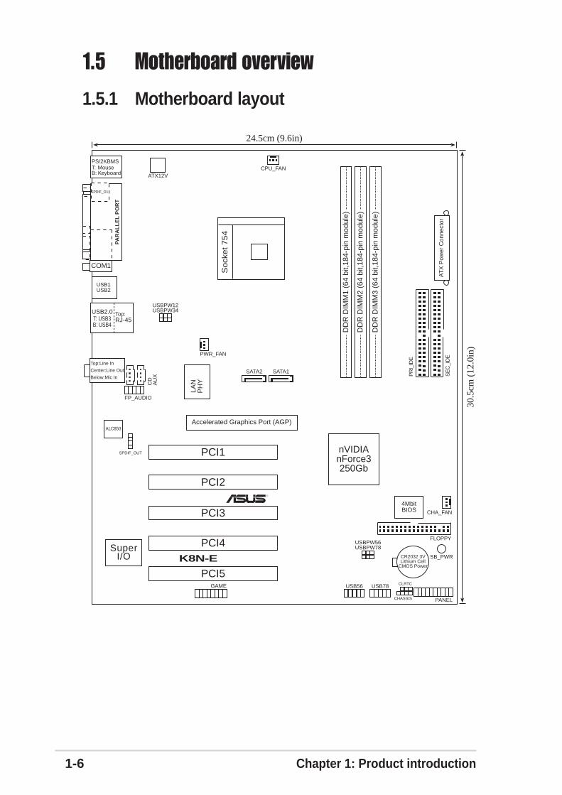
1.5 Motherboard overview
1.5.1 Motherboard layout
PCI1
PANEL
K8N-E
R
CR2032 3VLithium Cell
CMOS Power
CD
AU
X
SuperI/O
4MbitBIOS
Accelerated Graphics Port (AGP)
FP_AUDIO
ALC850
USB2.0T: USB3B: USB4
Top:RJ-45
GAME
ATX12V
CHASSIS
PR
I_ID
E
SE
C_I
DE
ATX
Pow
er C
onne
ctor
USB1USB2
nVIDIAnForce3250Gb
LAN
PH
Y
USB78
SB_PWR
CHA_FAN
USBPW12USBPW34
24.5cm (9.6in)
30.5
cm (
12.0
in)
PS/2KBMST: MouseB: Keyboard
DD
R D
IMM
1 (6
4 bi
t,184
-pin
mod
ule)
DD
R D
IMM
2 (6
4 bi
t,184
-pin
mod
ule)
DD
R D
IMM
3 (6
4 bi
t,184
-pin
mod
ule)
PCI2
PCI3
PCI4
PCI5
SATA1
USB56
SATA2
CPU_FAN
PWR_FAN
So
cke
t 7
54
CLRTC
Below:Mic In
Center:Line Out
Top:Line In
FLOPPY
PAR
AL
LE
L P
OR
T
COM1
SPDIF_O1
USBPW56USBPW78
SPDIF_OUT

ASUS K8N-E 1-7
®
K8N-E
Do not overtighten the screws! Doing so may damage the motherboard.
1.5.2 Placement directionWhen installing the motherboard, make sure that you place it into the chassis inthe correct orientation. The edge with external ports goes to the rear part of thechassis as indicated in the image below.
1.5.3 Screw holesPlace nine (9) screws into the holes indicated by circles to secure the motherboardto the chassis.
Place this side towardsthe rear of the chassis

1-8 Chapter 1: Product introduction
1.6 Central Processing Unit (CPU)
1.6.1 OverviewThe motherboard comes with a surface mount 754-pin Zero Insertion Force (ZIF)socket designed for the AMD Athlon™ 64 and AMD Sempron™ processors.
The 128-bit-wide data paths of these processors can run applications faster thanprocessors with only 32-bit or 64-bit wide data paths.
Incorrect installation of the CPU into the socket may bend the pins and severelydamage the CPU!
K8N-E
®
K8N-E CPU Socket 754Gold Arrow

ASUS K8N-E 1-9
1.6.2 Installing the CPUFollow these steps to install a CPU.
1. Locate the 754-pin ZIF socket on the motherboard.
3. Position the CPU above the socketsuch that the CPU corner with thegold triangle matches the socketcorner with a small triangle.
4. Carefully insert the CPU into thesocket until it fits in place.
2. Unlock the socket by pressing thelever sideways, then lift it up to a90°-100° angle.
Make sure that the socket lever is lifted up to 90°-100° angle, otherwise theCPU does not fit in completely.
The CPU fits only in one correct orientation. DO NOT force the CPU into thesocket to prevent bending the pins and damaging the CPU!
Socket Lever
Gold triangle
Small triangle
5. When the CPU is in place, pushdown the socket lever to secure theCPU. The lever clicks on the side tabto indicate that it is locked.
6. Install specifically designed heatsinkand fan assembly.

1-10 Chapter 1: Product introduction
1.7 System memory
1.7.1 DIMM sockets locationThe following figure illustrates the location of the DDR DIMM sockets.
1.7.2 Memory configurationsYou may install 64MB, 128MB, 256MB, 512MB, and 1GB DDR DIMMs into theDIMM sockets using the memory configurations in this section.
Important notes
Make sure to unplug the power supply before adding or removing DIMMs orother system components. Failure to do so may cause severe damage to boththe motherboard and the components.
• Installing DDR DIMMs other than the given memory configurations maycause memory sizing error or system boot failure. Use any of the memoryconfigurations in Table 1.
• For optimum compatibility, obtain memory modules from qualifiedvendors. See Qualified Vendors List on page 1-11.
• Stacked RAM and DDR DIMM modules with more than 18 chips are notsupported.
• Always install DIMMs with the same CAS Latency. For optimumcompatibility, obtain memory modules from the same vendors. SeeQualified Vendors List on page 1-11.
Obtain DDR DIMMs only from ASUS qualified vendors for better systemperformance. Visit the ASUS website (www.asus.com) for the latest DDR 400Qualified Vendor List for this motherboard.
K8N-E
®
K8N-E 184-pin DDR DIMM sockets
80 P
ins
104
Pin
sD
IMM
1
DIM
M2
DIM
M3

ASUS K8N-E 1-11
DDR Qualified Vendors ListThe following table lists the PC3200 (DDR400) memory modules that have beentested and qualified for use with this motherboard. Visit the ASUS website(www.asus.com) for the latest DDR 400 QVL for this motherboard.
Table 1 Memory configurations
Legend: SS - Single-Sided DIMMs DS - Double-Sided DIMMs
Number of DIMM Slot DIMMs DIMM1 DIMM2 DIMM3 Max Speed
1 Single Side - - DDR 4001 - Single Side - DDR 4001 - - Single Side DDR 4001 Double Side - - DDR 4001 - Double Side - DDR 4001 - - Double Side DDR 4002 Single Side Single Side - DDR 4002 Single Side Double Side - DDR 4002 Single Side - Single Side DDR 4002 Single Side - Double Side DDR 4002 Double Side Single Side - DDR 4002 Double Side Double Side - DDR 3332 Double Side - Single Side DDR 4002 - Single Side Single Side DDR 3332 - Single Side Double Side DDR 2002 - Double Side Single Side DDR 2002 - Double Side Double Side DDR 2002 Double Side - Double Side DDR 3333 Single Side Single Side Single Side DDR 3333 Single Side Single Side Double Side DDR 2003 Single Side Double Side Single Side DDR 2003 Single Side Double Side Double Side DDR 2003 Double Side Single Side Single Side DDR 3333 Double Side Single Side Double Side DDR 2003 Double Side Double Side Single Side DDR 2003 Double Side Double Side Double Side DDR 200
DIMM Vendor Chip Number Chip Brand SS/DS Module Part Number Size
KINGSTON HY5DU56822BT-D43 Hynix SS KVR400X64C3A/256 256MBKINGSTON HY5DU56822BT-D43 Hynix DS KVR400X64C3A/512 512MBKINGSTON V58C2256804SAT5(ECC) Mosel SS KVR400X72C3A/256 256MBKINGSTON V58C2256804SAT5(ECC) Mosel DS KVR400X72C3A/512 512MBKINGSTON HYB25D256800BT-5B Infineon SS KVR400X64C3A/256 256MBKINGSTON HYB25D256809BT-5B Infineon DS KVR400X64C3A/512 512MBKINGSTON D3208DL2T-5 KINGSTON SS KVR400X64C3A/256 256MBKINGSTON D328DIB-50 KINGSTON DS KVR400X64C3A/512 512MBKINGSTON Heat-Sink Package N/A DS KHX3200A/512 512MBSAMSUNG K4H560838E-TCCC(ECC) SAMSUNG SS M381L3223ETM-CCC 256MBSAMSUNG K4H560838E-TCCC(ECC) SAMSUNG DS M381L6423ETM-CCC 512MBSAMSUNG K4H560838E-TCCC SAMSUNG SS M368L3223ETM-CCC 256MBSAMSUNG K4H560838E-TCCC SAMSUNG DS M368L6423ETM-CCC 512MBSAMSUNG K4H560838F-TCCC SAMSUNG SS M368L3223FTN-CCC 256MBSAMSUNG K4H560838F-TCCC SAMSUNG DS M368L6423FTN-CCC 256MBHynix HY5DU56822BT-D43 Hynix SS HYMD232646B8J-D43 AA 256MBHynix HY5DU56822BT-D43 Hynix DS HYMD264646B8J-D43 AA 512MBMICRON MT46V32M8TG-5BC MICRON SS MT8VDDT3264AG-40BCB 256MBMICRON MT46V32M8TG-5BC MICRON DS MT16VDDT6464AG-40BCB 512MBInfineon HYB25D256800BT-5B Infineon SS HYS64D32300GU-5-B 256MBInfineon HYB25D256800BT-5B Infineon DS HYS64D64320GU-5-B 512MBInfineon HYB25D256800CE-5C Infineon SS HYS64D32300HU-5-C 256MBInfineon HYB25D256800CE-5C Infineon DS HYS64D64320HU-5-C 512MBCORSAIR W942508BH-5 Winbond SS CMX256A-3200C2PT 256MBCORSAIR Heat-Sink Package Winbond DS CMX512-3200C2 512MB

1-12 Chapter 1: Product introduction
1.7.3 Installing a DIMMFollow these steps to install a DIMM.
1. Unlock a DIMM socket by pressing theretaining clips outward.
2. Align a DIMM on the socket such that thenotch on the DIMM matches the break onthe socket.
3. Firmly insert the DIMM into the socketuntil the retaining clips snap back in placeand the DIMM is properly seated.
A DDR DIMM is keyed with a notch so that it fits in only one direction. DO NOTforce a DIMM into a socket to avoid damaging the DIMM.
Unlocked
DDR DIMM
1.8 Expansion slotsTo install and configure an expansion card:
1. Install an expansion card following the instructions that came with the chassis.
2. Turn on the system and change the necessary BIOS settings, if any. SeeChapter 2 for BIOS information.
3. Assign an IRQ to the card. Refer to the tables next page.
4. Install the drivers and/or software applications for the expansion cardaccording to the card documentation.
1.8.1 Standard interrupt assignmentsIRQ Priority Standard Function 0 1 System Timer 1 2 Keyboard Controller 2 N/A Programmable Interrupt 3* 11 IRQ holder for PCI steering 4* 12 Communications Port (COM1) 5* 13 IRQ holder for PCI steering 6 14 Floppy Disk Controller 7* 15 Printer Port (LPT1) 8 3 System CMOS/Real Time Clock 9* 4 IRQ holder for PCI steering10* 5 IRQ holder for PCI steering11* 6 IRQ holder for PCI steering12* 7 PS/2 Compatible Mouse Port13 8 Numeric Data Processor14* 9 Primary IDE Channel15* 10 Secondary IDE Channel
* These IRQs are usually available for ISA or PCI devices.

ASUS K8N-E 1-13
1.8.3 PCI slotsThe PCI slots support PCI cards such as a LAN card, SCSI card, USB card, andother cards that comply with PCI specifications.
When using PCI cards on shared slots, ensure that the drivers support “ShareIRQ” or that the cards do not need IRQ assignments. Otherwise, conflicts willarise between the two PCI groups, making the system unstable and the cardinoperable.
1.8.2 IRQ assignments for this motherboard
INT A INT B INT C INT D INT EPCI slot 1 shared — — — —PCI slot 2 — shared — — —PCI slot 3 — — shared — —PCI slot 4 — — — used —PCI slot 5 shared — — — —AGP slot — — — — used

1-14 Chapter 1: Product introduction
1.8.4 AGP slotThe Accelerated Graphics Port (AGP) slot supports AGP 8X/4X (+1.5V) cards.When you buy an AGP card, make sure that you ask for one with +1.5Vspecification.
Note the notches on the card golden fingers to ensure that they fit the AGP slot onthe motherboard.
If installing the ATi 9500 or 9700 Pro Series VGA cards, use only the cardversion PN xxx-xxxxx-30 or later, for optimum performance and overclockingstability.
Install only +1.5V AGP cards.
K8N-E
®
K8N-E Accelerated Graphics Port (AGP)
Keyed for 1.5v

ASUS K8N-E 1-15
1.9 Jumpers1. Clear RTC RAM (CLRTC)
This jumper allows you to clear the Real Time Clock (RTC) RAM in CMOS.You can clear the CMOS memory of date, time, and system setup parametersby erasing the CMOS RTC RAM data. The RAM data in CMOS, that includesystem setup information such as system passwords, is powered by theonboard button cell battery.
To erase the RTC RAM:
1. Turn OFF the computer and unplug the power cord.
2. Move the jumper cap from pins 1-2 (default) to pins 2-3. Keep the cap onpins 2-3 for about 5~10 seconds, then move the cap back to pins 1-2.
3. Plug the power cord and turn ON the computer.
4. Hold down the <Del> key during the boot process and enter BIOS setup tore-enter data.
Except when clearing the RTC RAM, never remove the cap on the jumperdefault position. Removing the cap will cause system boot failure!
You do not need to clear the RTC when the system hangs due to overclocking.For system failure due to overclocking, use the C.P.R. (CPU Parameter Recall)feature. Shut down and reboot the system so BIOS can automatically resetparameter settings to its previous values.
K8N-E
® 21 32
K8N-E Clear RTC RAM
CLRTC
Normal Clear CMOS(Default)

1-16 Chapter 1: Product introduction
2. USB device wake-up (3-pin USBPW12, USBPW34, USBPW56, USBPW78)
Set these jumpers to +5V to wake up the computer from S1 sleep mode (CPUstopped, DRAM refreshed, system running in low power mode) using theconnected USB devices. Set to +5VSB to wake up from S3 and S4 sleepmodes (no power to CPU, DRAM in slow refresh, power supply in reducedpower mode).
• The USB device wake-up feature requires a power supply that can provide500mA on the +5VSB lead for each USB port. Otherwise, the system wouldnot power up.
• The total current consumed must NOT exceed the power supply capability(+5VSB) whether under normal condition or in sleep mode.
K8N-E
®
K8N-E USB device wake-up
3221
+5V(Default)
+5VSB
USBPW56USBPW78
3221
+5V(Default)
+5VSB
USBPW12USBPW34

ASUS K8N-E 1-17
1.10 ConnectorsThis section describes and illustrates the motherboard rear panel and internalconnectors.
1.10.1 Rear panel connectors
1. PS/2 mouse port. This green 6-pin connector is for a PS/2 mouse.
2. Parallel port. This 25-pin port connects a parallel printer, a scanner, or otherdevices.
3. RJ-45 port. This port allows 10/100 connection to a Local Area Network (LAN)through a network hub.
4. Line In port. This Line In (light blue) port connects a tape player or other audiosources.
5. Line Out port. This Line Out (lime) port connects a headphone or a speaker.In 4-channel, 6-channel and 8-channel mode, the function of this jack becomesFront Speaker Out.
6. Microphone port. This Mic (pink) port connects a microphone.
1
11 7
2 3
910
4
5
6
8
Audio 2, 4, or 6-channel configuration
Light Blue Line In Rear Speaker Out Rear Speaker Out
Lime Line Out Front Speaker Out Front Speaker Out
Pink Mic In Mic In Bass/Center Speaker
Port Headset/ 4-channel 6-channel2-channel
SPEEDLED
ACT/LINKLED
LAN port
LAN port LED indications ACT/LINK LED SPEED LED
Status Description Status Description
OFF No link OFF 10 Mbps connection
OFF Linked ORANGE 100 Mbps connection
BLINKING Data activity GREEN 1 Gbps connection
1-18 Chapter 1: Product introduction
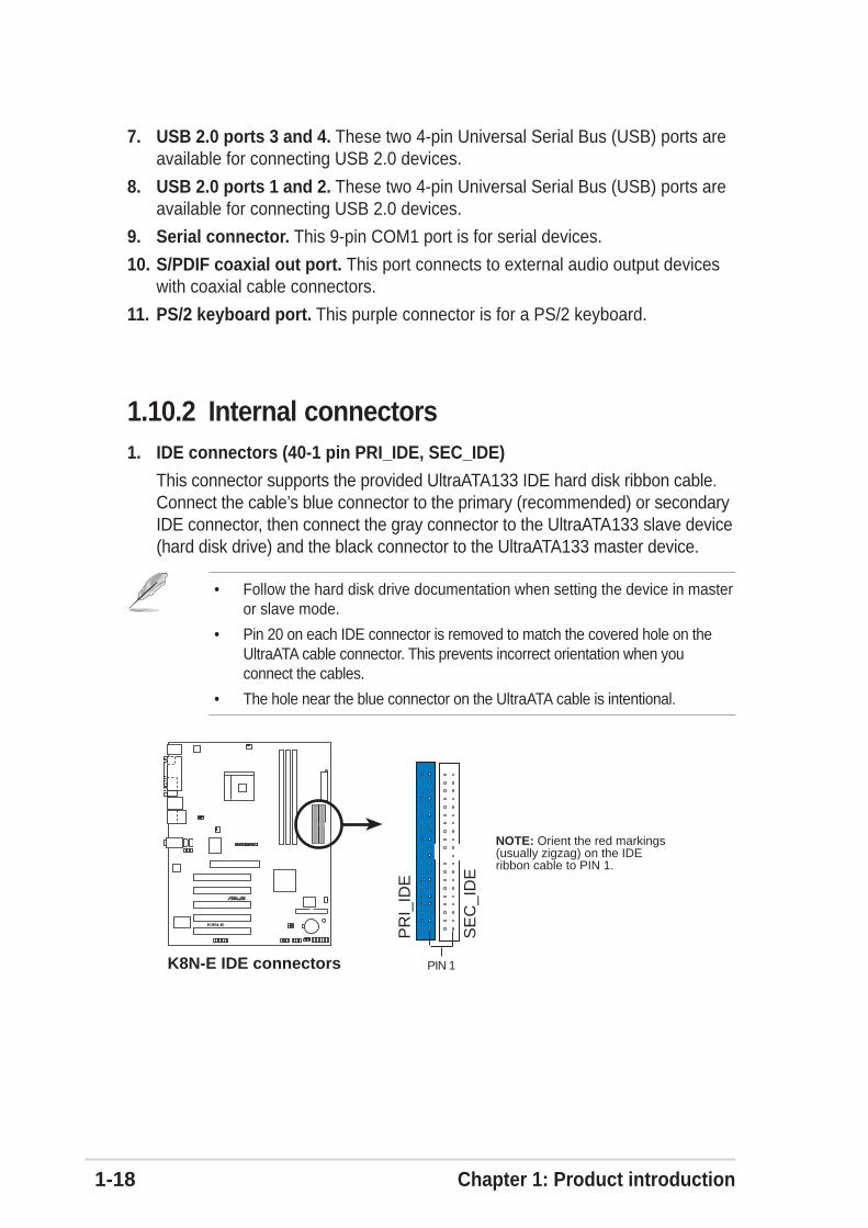
1.10.2 Internal connectors1. IDE connectors (40-1 pin PRI_IDE, SEC_IDE)
This connector supports the provided UltraATA133 IDE hard disk ribbon cable.Connect the cable’s blue connector to the primary (recommended) or secondaryIDE connector, then connect the gray connector to the UltraATA133 slave device(hard disk drive) and the black connector to the UltraATA133 master device.
• Follow the hard disk drive documentation when setting the device in masteror slave mode.
• Pin 20 on each IDE connector is removed to match the covered hole on theUltraATA cable connector. This prevents incorrect orientation when youconnect the cables.
• The hole near the blue connector on the UltraATA cable is intentional.
7. USB 2.0 ports 3 and 4. These two 4-pin Universal Serial Bus (USB) ports areavailable for connecting USB 2.0 devices.
8. USB 2.0 ports 1 and 2. These two 4-pin Universal Serial Bus (USB) ports areavailable for connecting USB 2.0 devices.
9. Serial connector. This 9-pin COM1 port is for serial devices.
10. S/PDIF coaxial out port. This port connects to external audio output deviceswith coaxial cable connectors.
11. PS/2 keyboard port. This purple connector is for a PS/2 keyboard.
K8N-E
®
K8N-E IDE connectors
NOTE: Orient the red markings(usually zigzag) on the IDEribbon cable to PIN 1.
SE
C_I
DE
PR
I_ID
E
PIN 1

ASUS K8N-E 1-19
2. Floppy disk drive connector (34-1 pin FLOPPY)
This connector supports the provided floppy drive ribbon cable. Afterconnecting one end to the motherboard, connect the other end to the floppydrive. (Pin 5 is removed to prevent incorrect insertion when using ribbon cableswith pin 5 plug).
K8N-E
®
K8N-E Floppy disk drive connector
NOTE: Orient the red markings onthe floppy ribbon cable to PIN 1.
FLOPPY PIN 1
3. Serial ATA connectors (7-pin SATA1, SATA2)
These next generation connectors support the thin Serial ATA cables forprimary internal storage devices. The current Serial ATA interface allows up to150 MB/s data transfer rate, faster than the standard parallel ATA with 133MB/s(Ultra ATA/133).These connectors support two Serial ATA hard disk drives thatyou can combine with the IDE connectors to configure a RAID set through thebuilt-in RAID controller.
K8N-E
®
K8N-E SATA connectors
SATA1
GN
DR
SAT
A_T
XP
1R
SAT
A_T
XN
1G
ND
RS
ATA
_RX
N1
RS
ATA
_RX
P1
GN
D
SATA2
GN
DR
SAT
A_T
XP
2R
SAT
A_T
XN
2G
ND
RS
ATA
_RX
N2
RS
ATA
_RX
P2
GN
D

1-20 Chapter 1: Product introduction
4. ATX power connectors (20-pin ATXPWR, 4-pin ATX12V)
These connectors connect to an ATX 12V power supply. The plugs from thepower supply are designed to fit these connectors in only one orientation. Findthe proper orientation and push down firmly until the connectors completely fit.
In addition to the 20-pin ATX power connector, this motherboard requires thatyou connect the 4-pin ATX +12V power plug to provide sufficient power to theCPU.
Make sure that your ATX 12V power supply can provide 8A on the +12V leadand at least 1A on the +5-volt standby lead (+5VSB). The minimumrecommended wattage is 300W or 350W for a fully configured system. Thesystem may become unstable and may experience difficulty powering up if thepower supply is inadequate.
5. Internal audio connectors (4-pin CD, AUX)
These connectors allow you to receive stereo audio input from sound sourcessuch as a CD-ROM, TV tuner, or MPEG card.
K8N-E
®
K8N-E ATX power connectors
ATXPWRATX12V
Pin 1
+3.3VDC-12.0VDCCOMPS_ON#
COMCOM
COM-5.0VDC+5.0VDC+5.0VDC
PWR_OK
+12.0VDC
+3.3VDC+3.3VDC
COM
+5.0VDCCOM
+5.0VDC
COM
+5VSB+12V DCGND
+12V DCGND
K8N-E
®
K8N-E Internal audio connectors
AUX (White)
Right Audio Channel
Left Audio Channel
Ground
CD (Black)

ASUS K8N-E 1-21
6. CPU and chassis fan connectors (3-pin CPU_FAN, PWR_FAN, CHA_FAN)
The fan connectors support cooling fans of 350mA~740mA (8.88W max.) or atotal of 1A~2.22A (26.64W max.) at +12V. Connect the fan cables to the fanconnectors on the motherboard, making sure that the black wire of each cablematches the ground pin of the connector.
Do not forget to connect the fan cables to the fan connectors. Lack of sufficientair flow within the system may damage the motherboard components. Theseare not jumpers! DO NOT place jumper caps on the fan connectors!
7. USB header (10-1 pin USB56, USB78)
If the USB ports on the rear panel are inadequate, a USB header is availablefor additional USB ports. Connect the USB cable of the USB 2.0 module to thisheader. You may install the USB module in the chassis front panel. Themodule has two USB 2.0 ports for connecting next generation USB peripheralssuch as high resolution cameras, scanners, and printers.
• The USB 2.0 module is purchased separately.• Install the USB 2.0 driver before using the USB 2.0 feature.
K8N-E
®
K8N-E Fan connectors
CPU_FAN
CHA_FAN
GN
D
Rot
atio
n+
12V
PWR_FANGND
Rotation+12V
GND
Rotation+12V
K8N-E
®
K8N-E USB connectors
USB56
US
B+
5VU
SB
_P6-
US
B_P
6+G
ND
NC
US
B+
5VU
SB
_P5-
US
B_P
5+G
ND
1USB78
US
B+
5VU
SB
_P8-
US
B_P
8+G
ND
NC
US
B+
5VU
SB
_P7-
US
B_P
7+G
ND
1

1-22 Chapter 1: Product introduction
9. Chassis intrusion connector (4-1 pin CHASSIS)
This lead is for a chassis designed with intrusion detection feature. Thisrequires an external detection mechanism such as a chassis intrusion sensoror microswitch. When you remove any chassis component, the sensor triggersand sends a high-level signal to this lead to record a chassis intrusion event.
By default, the pins labeled “Chassis Signal” and “Ground” are shorted with ajumper cap. If you wish to use the chassis intrusion detection feature, removethe jumper cap from the pins.
8. Front panel audio connector (10-1 pin FP_AUDIO)
This is an interface for the front panel cable that allows convenient connectionand control of audio devices.
Be default, the pins labeled LINE OUT_R/BLINE_OUT_R and the pinsLINE OUT_L/BLINE_OUT_L are shorted with jumper caps. Remove the capsonly when you are connecting the front panel audio cable.
K8N-E
®
K8N-E Front panel audio connector
FP_AUDIO
BLI
NE
_OU
T_L
MIC
2
Line
out
_R
Line
out
_L
BLI
NE
_OU
T_R
NC
MIC
PW
R+
5VA
AG
ND
K8N-E
®
K8N-E Chassis intrusion connector
CHASSIS
+5V
SB
_MB
Cha
ssis
Sig
nal
GN
D
(Default)
ASUS K8N-E 1-23
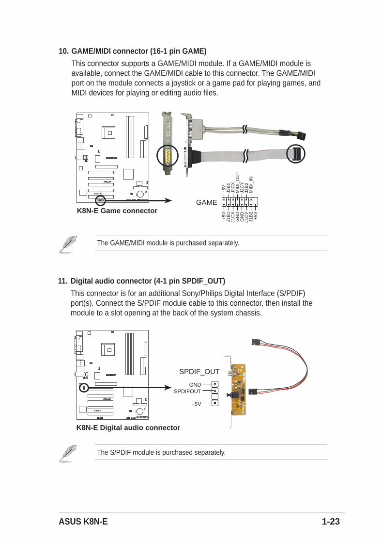
10. GAME/MIDI connector (16-1 pin GAME)
This connector supports a GAME/MIDI module. If a GAME/MIDI module isavailable, connect the GAME/MIDI cable to this connector. The GAME/MIDIport on the module connects a joystick or a game pad for playing games, andMIDI devices for playing or editing audio files.
The GAME/MIDI module is purchased separately.
K8N-E
®
K8N-E Game connectorGAME
+5V
+5V
J2B
1J2
CX
MID
I_O
UT
J2C
YJ2
B2
MID
I_IN
J1B
1J1
CX
GN
DG
ND
J1C
YJ1
B2
+5V
11. Digital audio connector (4-1 pin SPDIF_OUT)
This connector is for an additional Sony/Philips Digital Interface (S/PDIF)port(s). Connect the S/PDIF module cable to this connector, then install themodule to a slot opening at the back of the system chassis.
The S/PDIF module is purchased separately.
K8N-E
®
K8N-E Digital audio connector
+5V
SPDIFOUTGND
SPDIF_OUT
1-24 Chapter 1: Product introduction
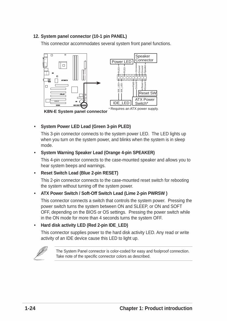
The System Panel connector is color-coded for easy and foolproof connection.Take note of the specific connector colors as described.
12. System panel connector (10-1 pin PANEL)
This connector accommodates several system front panel functions.
• System Power LED Lead (Green 3-pin PLED)
This 3-pin connector connects to the system power LED. The LED lights upwhen you turn on the system power, and blinks when the system is in sleepmode.
• System Warning Speaker Lead (Orange 4-pin SPEAKER)
This 4-pin connector connects to the case-mounted speaker and allows you tohear system beeps and warnings.
• Reset Switch Lead (Blue 2-pin RESET)
This 2-pin connector connects to the case-mounted reset switch for rebootingthe system without turning off the system power.
• ATX Power Switch / Soft-Off Switch Lead (Lime 2-pin PWRSW )
This connector connects a switch that controls the system power. Pressing thepower switch turns the system between ON and SLEEP, or ON and SOFTOFF, depending on the BIOS or OS settings. Pressing the power switch whilein the ON mode for more than 4 seconds turns the system OFF.
• Hard disk activity LED (Red 2-pin IDE_LED)
This connector supplies power to the hard disk activity LED. Any read or writeactivity of an IDE device cause this LED to light up.
K8N-E
®
K8N-E System panel connector* Requires an ATX power supply.
PLE
D-
PW
R+
5V Spe
aker
SpeakerConnectorPower LED
Gro
und
Reset SW
IDE_LED
IDE
_LE
D+
Gro
und
Res
etG
roun
dG
roun
d
ATX PowerSwitch*
PLE
D+
IDE
_LE
D-

ASUS K8N-E 2-1
Chapter 2
This chapter tells how to change system settingsthrough the BIOS Setup menus. Detaileddescriptions of the BIOS parameters are alsoprovided.
BIOS information

2-2 Chapter 2: BIOS Setup
2.1 Managing and updating your BIOSThe following utilities allow you to manage and update the motherboard BasicInput/Output System (BIOS) setup.
1. ASUS AFUDOS - Updates the BIOS using a bootable floppy disk in DOSmode.
2. ASUS EZ Flash - Updates the BIOS using a floppy disk during POST.
3. ASUS CrashFree BIOS 2 - Updates the BIOS using a bootable floppy disk orthe motherboard support CD.
Refer to the corresponding sections for details on these utilities.
Important notes
2.1.1 Creating a bootable floppy disk1. Do either one of the following to create a bootable floppy disk.
DOS environment
Insert a 1.44 MB floppy disk into the drive. At the DOS prompt, type:
format A:/S then press <Enter>.
Windows® 98SE/ME/XP environment
a. Insert a 1.44 MB floppy disk into the floppy disk drive.b. From your Windows desktop, click on Start, then select My Computer.c. Select the 3 1/2 Floppy Drive icon.d. Click File from the menu, then select Format. A Format 3 1/2 Floppy Disk
window appears.e. If you are using Windows® XP, select Create an MS-DOS startup disk
from the format options field, then click Start.ORIf you are using Windows® 98SE/ME, select Full option button from theformat type, then click Start.
Windows® 2000 environment
To create a set of boot disks for Windows® 2000, run the Makeboot.exe toolfrom the Windows® 2000 CD:
a. Insert a 1.44 MB floppy disk into the floppy disk drive.
b. Insert the Windows® 2000 CD into the CD-ROM drive.
• It is recommended that you save a copy of the original motherboardBIOS file to a bootable floppy disk in case you need to restore the BIOSin the future. Copy the original motherboard BIOS using AFUDOS (refer tosection “2.1.3 Using AFUDOS to copy BIOS from PC”)
• Visit the ASUS website and download the latest BIOS file for thismotherboard using the ASUS Update utility.

ASUS K8N-E 2-3
The BIOS information on the screen is for reference only. What you see on yourscreen may not be exactly the same as shown.
DO NOT shutdown or reset the system while updating the BIOS! Doing so maycause system boot failure!
2.1.2 Using AFUDOS to update the BIOSTo update the BIOS using the AFUDOS.EXE utility:
1. Visit the ASUS website (www.asus.com) to download the latest BIOS file foryour motherboard. Save the BIOS file to a bootable floppy disk.
2. Copy the AFUDOS.EXE utility from the support CD to the bootable floppy diskthat contains the BIOS file.
3. Boot the system from the floppy disk.
4. At the DOS prompt, type the command line:
afudos /i[filename]
where [filename] means the latest (or original) BIOS file that you copied tothe bootable floppy disk.
5. Press <Enter>. The succeeding screen displays the status of the updateprocess.
Write the BIOS file name on a piece of paper. You need to type the exact BIOSfile name at the prompt.
A:\>afudos /iK8NEB.ROMAMI Firmware Update Utility - Version 1.10Copyright (C) 2002 American Megatrends, Inc. All rights reserved.
Reading file ..... doneErasing flash .... doneWriting flash .... 0x0008CC00 (9%)
c. Click Start, then select Run.
d. From the Open box, type
D:\bootdisk\makeboot a: then press <Enter>,
assuming that D: is your CD-ROM drive.
e. Follow succeeding screen instructions.
2. Copy the original (or the latest) motherboard BIOS to the bootable floppy disk.

2-4 Chapter 2: BIOS Setup
Main filename
Extension name
A:\>afudos /oMYBIOS03.rom
AMI Firmware Update Utility - Version 1.10
Copyright (C) 2002 American Megatrends, Inc. All rights reserved.
Reading flash ..... 0x0008CC00 (9%)
The BIOS information on the screen is for reference only. What you see on yourscreen may not be exactly the same as shown.
When the BIOS update process is complete, the utility returns to the DOSprompt.
A:\>afudos /iK8NEB.ROMAMI Firmware Update Utility - Version 1.10Copyright (C) 2002 American Megatrends, Inc. All rights reserved.
Reading file ..... doneErasing flash .... doneWriting flash .... 0x0008CC00 (9%)Verifying flash .. done
A:\>
5. Reboot the system from the hard disk.
2.1.3 Using AFUDOS to copy BIOS from PCYou can use the AFUDOS.EXE utility to copy the current system BIOS to a floppyor hard disk and use it as a backup in case the system BIOS fails or getscorrupted.
To copy the BIOS from your PC using AFUDOS.EXE:
1. At the DOS prompt, type the command line:
afudos /o[filename]
where [filename] string of not more than eight (8) alpha-numeric charactersfor the main filename and three (3) alpha-numeric characters for the extensionname.
2. Press <Enter>.
ASUS K8N-E 2-5
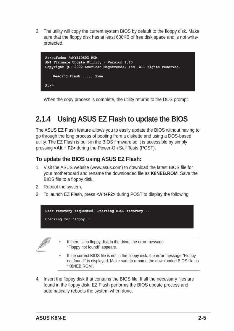
3. The utility will copy the current system BIOS by default to the floppy disk. Makesure that the floppy disk has at least 600KB of free disk space and is not write-protected.
A:\>afudos /oMYBIOS03.ROMAMI Firmware Update Utility - Version 1.10Copyright (C) 2002 American Megatrends, Inc. All rights reserved.
Reading flash ..... done
A:\>
When the copy process is complete, the utility returns to the DOS prompt.
User recovery requested. Starting BIOS recovery...
Checking for floppy...
• If there is no floppy disk in the drive, the error message“Floppy not found!” appears.
• If the correct BIOS file is not in the floppy disk, the error message “Floppynot found!” is displayed. Make sure to rename the downloaded BIOS file as“K8NEB.ROM”.
2.1.4 Using ASUS EZ Flash to update the BIOSThe ASUS EZ Flash feature allows you to easily update the BIOS without having togo through the long process of booting from a diskette and using a DOS-basedutility. The EZ Flash is built-in the BIOS firmware so it is accessible by simplypressing <Alt + F2> during the Power-On Self Tests (POST).
To update the BIOS using ASUS EZ Flash:1. Visit the ASUS website (www.asus.com) to download the latest BIOS file for
your motherboard and rename the downloaded file as K8NEB.ROM. Save theBIOS file to a floppy disk.
2. Reboot the system.
3. To launch EZ Flash, press <Alt+F2> during POST to display the following.
4. Insert the floppy disk that contains the BIOS file. If all the necessary files arefound in the floppy disk, EZ Flash performs the BIOS update process andautomatically reboots the system when done.

2-6 Chapter 2: BIOS Setup
User recovery requested. Starting BIOS recovery...Checking for floppy...Floppy found!Reading file “K8NEB.ROM”. Completed.Start flashing...Flashed successfully. Rebooting.
DO NOT shutdown or reset the system while updating the BIOS! Doing so maycause system boot failure!
2.1.5 ASUS CrashFree BIOS 2 utilityThe ASUS CrashFree BIOS 2 is an auto recovery tool that allows you to restorethe BIOS file when it fails or gets corrupted during the updating process. You canupdate a corrupted BIOS file using the motherboard support CD or the floppy diskthat contains the updated BIOS file.
Prepare the motherboard support CD or the floppy disk containing the updatedmotherboard BIOS before using this utility.
Recovering the BIOS from the support CDTo recover the BIOS from the support CD:
1. Turn on the system.
2. Insert the motherboard support CD to the optical drive.
3. The utility displays the following message and automatically checks the CD forthe BIOS file.
Award BootBlock BIOS v1.0
Copyright (c) 2000, Award Software, Inc.
BIOS ROM checksum error
Detecting IDE ATAPI device...
Found CDROM, try to Boot from it... Pass
When found, the utility reads the BIOS file and starts flashing the corruptedBIOS file.
Award BootBlock BIOS v1.0
Copyright (c) 2000, Award Software, Inc.
BIOS ROM checksum error
Detecting IDE ATAPI device...

ASUS K8N-E 2-7
4. Restart the system after the utility completes the updating process.
DO NOT shut down or reset the system while updating the BIOS! Doing so cancause system boot failure!
Recovering the BIOS from a floppy diskTo recover the BIOS from a floppy disk:
1. Remove any CD from the optical drive, then turn on the system.
2. Insert the floppy disk with the original or updated BIOS file to the floppy diskdrive.
3. The utility displays the following message and automatically checks the floppydisk for the original or updated BIOS file.
When no CD is found, the utility automatically checks the floppy drive for theoriginal or updated BIOS file. The utility then updates the corrupted BIOS file.
Award BootBlock BIOS v1.0
Copyright (c) 2000, Award Software, Inc.
BIOS ROM checksum error
Detecting IDE ATAPI device...
The recovered BIOS may not be the latest BIOS version for this motherboard.Visit the ASUS website (www.asus.com) to download the latest BIOS file.
4. Restart the system after the utility completes the updating process.
DO NOT shut down or reset the system while updating the BIOS! Doing so cancause system boot failure!
Award BootBlock BIOS v1.0
Copyright (c) 2000, Award Software, Inc.
BIOS ROM checksum error
Detecting IDE ATAPI device...
Found CDROM, try to Boot from it... Fail
Detecting floppy drive A media...

2-8 Chapter 2: BIOS Setup
2.2 BIOS Setup programThis motherboard supports a programmable firmware chip that you can updateusing the provided utility described in section “4.1 Managing and updating yourBIOS.”
Use the BIOS Setup program when you are installing a motherboard, reconfiguringyour system, or prompted to “Run Setup”. This section explains how to configureyour system using this utility.
Even if you are not prompted to use the Setup program, you may want to changethe configuration of your computer in the future. For example, you may want toenable the security password feature or change the power management settings.This requires you to reconfigure your system using the BIOS Setup program sothat the computer can recognize these changes and record them in the CMOSRAM of the firmware hub.
The firmware hub on the motherboard stores the Setup utility. When you start upthe computer, the system provides you with the opportunity to run this program.Press <Del> during the Power-On Self Test (POST) to enter the Setup utility.Otherwise, POST continues with its test routines.
If you wish to enter Setup after POST, restart the system by pressing<Ctrl+Alt+Delete>, or by pressing the reset button on the system chassis. You canalso restart by turning the system off and then back on. Do this last option only ifthe first two failed.
The Setup program is designed to make it as easy to use as possible. It is a menu-driven program, which means you can scroll through the various sub-menus andmake your selections from the available options using the navigation keys.
The default BIOS settings for this motherboard apply for most conditions toensure optimum performance. If the system becomes unstable after changingany BIOS settings, load the default settings to ensure system compatibility andstability. Select the Load Default Settings item under the Exit Menu. Seesection “2.7 Exit Menu.”
The BIOS setup screens shown in this chapter are for reference purposes only,and may not exactly match what you see on your screen.
Visit the ASUS website (www.asus.com) to download the latest product andBIOS information.

ASUS K8N-E 2-9
System Time [11:51:19]System Date [Thu 06/05/2005]Legacy Diskette A [1.44M, 3.5 in]
Primary IDE Master : [ST320413A]Primary IDE Slave : [ASUS CD-S340]Secondary IDE Master : [Not Detected]Secondary IDE Slave : [Not Detected]
System Information
Use [ENTER], [TAB]or [SHIFT-TAB] toselect a field.
Use [+] or [-] toconfigure systemtime.
2.2.2 Menu barThe menu bar on top of the screen has the following main items:
Main For changing the basic system configuration
Advanced For changing the advanced system settings
Power For changing the advanced power management (APM)configuration
Boot For changing the system boot configuration
Exit For selecting the exit options and loading default settings
2.2.1 BIOS menu screen
To select an item on the menu bar, press the right or left arrow key on the keyboarduntil the desired item is highlighted.
2.2.3 Navigation keysAt the bottom right corner of a menu screen are the navigation keys for thatparticular menu. Use the navigation keys to select items in the menu and changethe settings.
Some of the navigation keys differ from one screen to another.
Navigation keys
General helpMenu bar
Sub-menu items
Configuration fieldsMenu items

2-10 Chapter 2: BIOS Setup
2.2.4 Menu itemsThe highlighted item on the menu bardisplays the specific items for that menu. Forexample, selecting Main shows the Mainmenu items.
The other items (Advanced, Power, Boot,and Exit) on the menu bar have theirrespective menu items.
2.2.5 Sub-menu itemsAn item with a sub-menu on any menu screen is distinguished by a solid trianglebefore the item. To display the sub-menu, select the item and press <Enter>.
2.2.6 Configuration fieldsThese fields show the values for the menu items. If an item is user-configurable,you may change the value of the field opposite the item. You can not select an itemthat is not user-configurable.
A configurable field is enclosed in brackets, and is highlighted when selected. Tochange the value of a field, select it then press <Enter> to display a list of options.Refer to “2.2.7 Pop-up window.”
2.2.7 Pop-up windowSelect a menu item then press <Enter> to display a pop-up window with theconfiguration options for that item.
2.2.8 Scroll barA scroll bar appears on the right side of amenu screen when there are items that donot fit on the screen. Press Up/Down arrow keys or PageUp/PageDownkeys to display the other items on thescreen.
2.2.9 General helpAt the top right corner of the menu screen is a brief description of the selecteditem.
System Time [11:51:19]System Date [Thu 08/05/2003]Legacy Diskette A [1.44M, 3.5 in]Language [English]
Primary IDE Master :[ST320413A] Primary IDE Slave :[ASUS CD-S340] Secondary IDE Master :[Not Detected] Secondary IDE Slave :[Not Detected]
System Information
Use [ENTER], [TAB]or [SHIFT-TAB] toselect a field.
Use [+] or [-] toconfigure system time.
Select Screen Select Item+- Change FieldTab Select FieldF1 General HelpF10 Save and ExitESC Exit
Main menu items
Scroll bar
Select Screen Select Item+- Change OptionF1 General HelpF10 Save and ExitESC Exit
Advanced Chipset settings
WARNING: Setting wrong values in the sections below may cause system to malfunction.
Configure DRAM Timing by SPD [Enabled]Memory Acceleration Mode [Auto]DRAM Idle Timer [Auto]DRAm Refresh Rate [Auto]
Graphic Adapter Priority [AGP/PCI]Graphics Aperture Size [ 64 MB]Spread Spectrum [Enabled]
ICH Delayed Transaction [Enabled]
MPS Revision [1.4]
Pop-up window

ASUS K8N-E 2-11
2.3 Main menuWhen you enter the BIOS Setup program, the Main menu screen appears, givingyou an overview of the basic system information.
2.3.1 System Time [xx:xx:xxxx]Allows you to set the system time.
2.3.2 System Date [Day xx/xx/xxxx]Allows you to set the system date.
2.3.3 Legacy Diskette A [1.44M, 3.5 in.]Sets the type of floppy drive installed.Configuration options: [Disabled] [360K, 5.25 in.] [1.2M , 5.25 in.] [720K , 3.5 in.][1.44M, 3.5 in.] [2.88M, 3.5 in.]
Refer to section “2.2.1 BIOS menu screen” for information on the menu screenitems and how to navigate through them.
System Time [11:51:19]System Date [Thu 08/05/2003]Legacy Diskette A [1.44M, 3.5 in]
Primary IDE Master :[ST320413A]Primary IDE Slave :[ASUS CD-S340]Secondary IDE Master :[Not Detected]Secondary IDE Slave :[Not Detected]Third IDE Master :[Not Detected]Third IDE Slave :[Not Detected]Fourth IDE Master :[Not Detected]Fourth IDE Slave :[Not Detected]
System Information
Use [ENTER], [TAB]or [SHIFT-TAB] toselect a field.
Use [+] or [-] toconfigure systemtime.

2-12 Chapter 2: BIOS Setup
2.3.4 Primary and Secondary IDE Master/SlaveWhile entering Setup, BIOS auto-detects the presence of IDE devices. There is aseparate sub-menu for each IDE device. Select a device item then press <Enter>to display the IDE device information.
The values opposite the dimmed items (Device, Vendor, Size, LBA Mode, BlockMode, PIO Mode, Async DMA, Ultra DMA, and SMART monitoring) are auto-detected by BIOS and are not user-configurable. These items show N/A if no IDEdevice is installed in the system.
Type [Auto]
Selects the type of IDE drive. Setting to Auto allows automatic selection of theappropriate IDE device type. Select CDROM if you are specifically configuringa CD-ROM drive. Select ARMD (ATAPI Removable Media Device) if yourdevice is either a ZIP, LS-120, or MO drive.Configuration options: [Not Installed] [Auto] [CDROM] [ARMD]
LBA/Large Mode [Auto]
Enables or disables the LBA mode. Setting to Auto enables the LBA mode ifthe device supports this mode, and if the device was not previously formattedwith LBA mode disabled. Configuration options: [Disabled] [Auto]
Block (Multi-sector Transfer) [Auto]
Enables or disables data multi-sectors transfers. When set to Auto, the datatransfer from and to the device occurs multiple sectors at a time if the devicesupports multi-sector transfer feature. When set to Disabled, the data transferfrom and to the device occurs one sector at a time.Configuration options: [Disabled] [Auto]
Primary IDE Master
Device : Hard DiskVendor : Maxtor 6Y080L0Size : 81.9GBLBA Mode : SupportedBlock Mode : 16 SectorsPIO Mode : 4Async DMA : MultiWord DMA-2Ultra DMA : Ultra DMA-5SMART Monitoring: Supported
Type [Auto]LBA/Large Mode [Auto]Block(Multi-sector Transfer) [Auto]PIO Mode [Auto]DMA Mode [Auto]Smart Monitoring [Auto]32Bit Data Transfer [Disabled]
Select the typeof device connectedto the system

ASUS K8N-E 2-13
2.3.5 System InformationThis menu gives you an overview of the general system specifications. The itemsin this menu are auto-detected by BIOS.
AMI BIOS
Displays the auto-detected BIOS information.
Processor
Displays the auto-detected processor information.
System Memory
Displays the auto-detected system memory.
PIO Mode [Auto]
Selects the PIO mode. Configuration options: [Auto] [0] [1] [2] [3] [4]
DMA Mode [Auto]
Selects the DMA mode. Configuration options: [Auto] [SWDMA0] [SWDMA1][SWDMA2] [MWDMA0] [MWDMA1] [MWDMA2] [UDMA0] [UDMA1] [UDMA2][UDMA3] [UDMA4] [UDMA5] [UDMA6]
SMART Monitoring [Auto]
Sets the Smart Monitoring, Analysis, and Reporting Technology.Configuration options: [Auto] [Disabled] [Enabled]
32Bit Data Transfer [Disabled]
Enables or disables 32-bit data transfer.Configuration options: [Disabled] [Enabled]
AMI BIOSVersion : 08.00.09Build Date : 06/07/05
ProcessorType : AMD Athlon(tm) 64 Processor 3200+Speed : 2000MHzCount : 1
System MemorySize : 512MB
2-14 Chapter 2: BIOS Setup
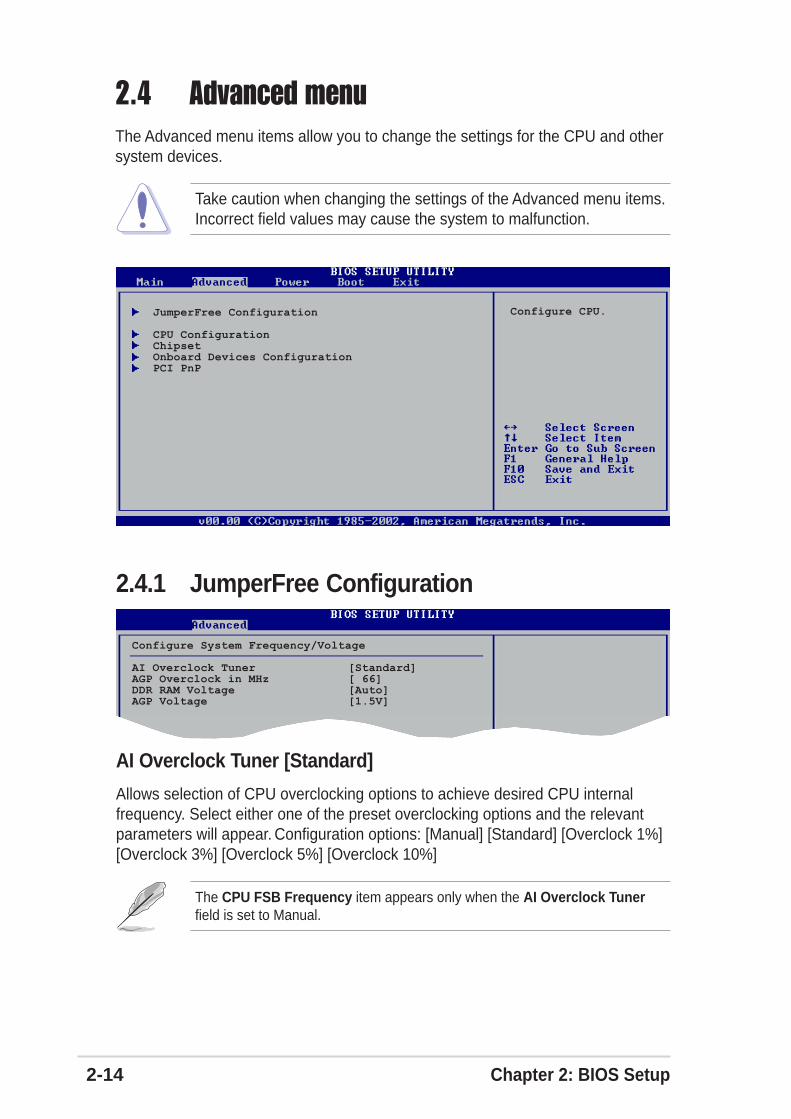
2.4.1 JumperFree Configuration
Configure System Frequency/Voltage
AI Overclock Tuner [Standard]AGP Overclock in MHz [ 66]DDR RAM Voltage [Auto]AGP Voltage [1.5V]
AI Overclock Tuner [Standard]
Allows selection of CPU overclocking options to achieve desired CPU internalfrequency. Select either one of the preset overclocking options and the relevantparameters will appear. Configuration options: [Manual] [Standard] [Overclock 1%][Overclock 3%] [Overclock 5%] [Overclock 10%]
The CPU FSB Frequency item appears only when the AI Overclock Tunerfield is set to Manual.
2.4 Advanced menuThe Advanced menu items allow you to change the settings for the CPU and othersystem devices.
Take caution when changing the settings of the Advanced menu items.Incorrect field values may cause the system to malfunction.
JumperFree Configuration
CPU ConfigurationChipsetOnboard Devices ConfigurationPCI PnP
Configure CPU.

ASUS K8N-E 2-15
Selecting a very high CPU frequency may cause the system to becomeunstable! If this happens, revert to the default setting.
CPU FSB Frequency [xxx]
Allows you to adjust the CPU FSB operating frequency. The FSB frequencyconfiguration ranges from 200 to 300 MHz. Use the plus <+> or minus <-> keys toadjust the values.
AGP Overclock in MHz [ 66]
Allows you to adjust the AGP slot clock. The AGP frequency configuration rangesfrom 66 to 75 MHz. Use the plus <+> or minus <-> keys to adjust the values.
FID/VID Change [Auto]
When set to Auto, the Frequency ID and Voltage ID will be based on the ratedfrequency and voltage. If you want to adjust the Processor Frequency Multiplierand CPU voltage, set this item to Manual. Configuration options: [Auto] [Manual]
Processor Frequency Multiplier [xxxxMhz]
Allows you to set the processor frequency multiplier. The default value andconfiguration options depend on the CPU installed.
CPU Voltage [x.xxxx V]
Allows you to set the CPU voltage. The default value and configuration optionsdepend on the CPU installed.
DDR RAM Voltage [Auto]
Allows you to automatically detect or select from a list the DDR operating voltage.Configuration options: [Auto] [2.5V] [2.6V] [2.7V] [2.8V]
AGP Voltage [1.5V]
Adjusts the AGP voltage setting. Configuration options: [1.5V] [1.6V] [1.7V]

2-16 Chapter 2: BIOS Setup
Cool N’ Quiet [Disabled]
Allows you to enable or disable the AMD Cool ‘n’ Quiet!™ Technology feature.Configuration options: [Enabled] [Disabled]
• Make sure that the above item is set to Enabled if you want to use theAMD CPU Cool ‘n’ Quiet!™ Technology feature.
• This feature requires the AMD CPU heatsink and fan assembly with monitorchip. If you purchased a separate heatsink and fan package, use the ASUSQ-Fan Technology feature to automatically adjust the CPU fan speedaccording to your system loading.
2.4.3 CPU ConfigurationThe items in this menu show the CPU-related information auto-detected by BIOS.
Type
Displays the processor type and properties installed in your system.
AMD Cool & Quiet Configuration
GART Error Reporting [Disabled]
Enables or disables the GART Error Reporting feature. This option should alwaysbe disabled for normal operation. Device driver developers may enable it fortesting purpose. Configuration options: [Disabled] [Enabled]
HT Ratio [4]
Sets the Hyper-Transport (HT) ratio. Configuration options: [1] [2] [3] [4]
Type : AMD Athlon(tm) 64 Processor 3200+
AMD Cool ‘N Quiet ConfigurationGART Error Reporting [Disabled]HT Ratio [4]
AMD Cool & Quiet Configuration
Cool N’Quiet [Disabled]
Enable/Disable AMDK8 Cool N’Quietfunction.

ASUS K8N-E 2-17
Memory CLK : 200 MHzCAS Latency : 2.5DRAM RAS TO CAS Delay : 3 CLKDRAM ACTIVE TIME : 8 CLKDRAM RAS PRECHANGE TIME : 3 CLKMemClock Mode [Auto]MCT Timing Mode [Auto]1T/2T Timing [Auto]Master ECC Enabled [Enabled]Audio CODEC Interface [Auto]Primary Video [PCI]Aperture Size [ 128 MB]AGP FW Enable [Auto]AGP SideBand Address [Auto] Onboard Device USB Configuration
MEMCLK can be setby the code usingAUTO, or if you useLIMIT, you can setone of the standardvalues.
2.4.4 ChipsetThe items in this menu show the chipset-related information auto-detected byBIOS.
Memclock Mode [ Auto]
Allows you to set the memory clock mode. Set by the code using [Auto] or select[Manual] to set using one of the standard values.Configuration options: [Auto] [Manual]
MemClock Value [200 MHz]
Sets the Memory clock value. This item appears only when the MemClock Modeitem is set to Manual. Configuration options: [200 MHz] [266 MHz] [333 MHz] [400 MHz]
MCT Timing Mode [Auto]
Sets the MCT timing mode. Configuration options: [Auto] [Manual]
CAS Latency (CL) [Auto]
Sets the CAS Latency value. Configuration options: [Auto] [2.0] [2.5] [3.0]
DRAM RAS TO CAS Delay [4 CLK]
Sets the DRAM RAS TO CAS Delay.Configuration options: [Auto] [2 CLK] [3 CLK] [4 CLK] [5 CLK] [6 CLK]
DRAM RAS PRECHANGE Time [4 CLK]
Sets the DRAM RAS PRECHANGE Time.Configuration options: [Auto] [2 CLK] [3 CLK] [4 CLK] [5 CLK] [6 CLK]

2-18 Chapter 2: BIOS Setup
DRAM ACTIVE TIME [Auto]
Sets the DRAM ACTIVE TIME. Configuration options: [Auto] [5 CLK] [6 CLK][7 CLK] [8 CLK] [9 CLK] [10 CLK] [11 CLK] [12 CLK] [13 CLK] [14 CLK] [15 CLK]
1T/2T Timing [Auto]
Sets the DRAM command timing. When set to Auto, the DRAM timing is set to 2T ifthe CPU installed can support 2T timing. Configuration options: [1T] [Auto]
Master ECC Enable [Disabled]
Enables or disables support on all nodes for ECC error detect and correction.Configuration options: [Disabled] [Enabled]
Audio CODEC Interface [Auto]
Allows you to set the onboard audio CODEC interface. [Auto] allows the BIOS todetect whether you are using any audio device.Configuration options: [Enabled] [Disabled] [Auto]
Primary Video [PCI]
Switches the PCI Bus scanning order while searching for a video card. This allowsyou to select the type of Primary VGA in case of multiple video controllers.Configuration options: [PCI] [AGP]
Aperture Size [ 128 MB]
Allows you to select the size of mapped memory for AGP graphic data.Configuration options: [32 MB] [64 MB] [128 MB] [256 MB] [512 MB]
AGP FW Enable [Auto]
Disables or sets to automatic the AGP Fast Write feature.Configuration options: [Auto] [Disabled]
AGP Sideband Address [Auto]
Disables or sets to automatic the AGP Sideband address.Configuration options: [Auto] [Disabled]

ASUS K8N-E 2-19
MAC Interface [Enabled]
Allows you to enable or disable the internal 802.3 MAC interface.Configuration options: [Enabled] [Disabled]
OnBoard LAN Boot ROM [Disabled]
Allows you to enable or disable the onboard LAN Boot ROM.Configuration options: [Disabled] [Enabled]
Internal SATA IDE Interface [Enabled]
Allows you to enable or disable the onchip Serial ATA and IDE interface.Configuration options: [Enabled] [Disabled]
RAID Option ROM [Disabled]
Allows you to enable or disable the onchip NVIDIA® Serial ATA boot ROM.Configuration options: [Disabled] [Enabled]
MAC Interface [Enabled]Onboard LAN Boot ROM [Disabled]Internal SATA IDE Interface [Enabled]RAID Option ROM [Disabled]
Onboard Device
The items in this sub-menu allows you to change the settings of the onboarddevices.
The following items appear only when RAID Option ROM item is set to Enabled.
Primary Master as RAID [Disabled]
Enables or disables the use of the Primary IDE Master as RAID.Configuration options: [Disabled] [Enabled]
Primary Slave as RAID [Disabled]
Enables or disables the use of the Primary IDE Slave as RAID.Configuration options: [Disabled] [Enabled]
Secondary Master as RAID [Disabled]
Enables or disables the use of the Secondary IDE Master as RAID.Configuration options: [Disabled] [Enabled]

2-20 Chapter 2: BIOS Setup
Secondary Slave as RAID [Disabled]
Enables or disables the use of the Secondary IDE Slave as RAID.Configuration options: [Disabled] [Enabled]
Third Master as RAID [Disabled]
Enables or disables the use of the Third IDE Master as RAID.Configuration options: [Disabled] [Enabled]
Fourth Master as RAID [Disabled]
Enables or disables the use of the Fourth IDE Master as RAID.Configuration options: [Disabled] [Enabled]
USB Configuration
The items in this menu allows you to change the USB-related features. Select anitem then press <Enter> to display the configuration options.
The Module Version and USB Devices Enabled items show the auto-detectedvalues. If no USB device is detected, the item shows None.
USB Configuration
Module Version - 2.23.2-7.4USB Devices Enabled: None
USB Controller Support [USB 1.1+USB 2.0]Legacy USB Support [Auto]USB 2.0 Controller Mode [HiSpeed]
Enables USBhost controllers.
USB Controller Support [USB 1.1+USB 2.0]
Allows you to disable or set the USB controller support type.Configuration options: [Disabled] [USB 1.1 only] [USB 1.1+USB 2.0]
Legacy USB Support [Auto]
Allows you to enable or disable support for legacy USB devices. Setting to Autoallows the system to detect the presence of USB devices at startup. If detected,the USB controller legacy mode is enabled. If no USB device is detected, thelegacy USB support is disabled. Configuration options: [Disabled] [Enabled] [Auto]
USB 2.0 Controller Mode [HiSpeed]
Allows you to configure the USB 2.0 controller in HiSpeed (480 Mbps) or FullSpeed (12 Mbps). Configuration options: [HiSpeed ] [Full Speed]

ASUS K8N-E 2-21
2.4.5 Onboard Devices Configuration
Configure ITE8712 Super IO Chipset
Serial Port1 Address [3F8/IRQ4]Parallel Port Address [378]Parallel Port Mode [EPP+ECP] EPP Version [1.9]
ECP Mode DMA Channel [DMA3] Parallel Port IRQ [IRQ7]OnBoard Game Port [Enabled]Onboard MIDI Port [300] MIDI IRQ Select [IRQ5]
Serial Port1 Address [3F8/IRQ4]
Allows you to select the Serial Port1 base address.Configuration options: [Disabled] [3F8/IRQ4] [2F8/IRQ3] [3E8/IRQ4] [2E8/IRQ3]
Parallel Port Address [378]
Allows you to select the Parallel Port base addresses.Configuration options: [Disabled] [378] [278]
The following items appear only when the Parallel Port Address item is set toEnabled.
Parallel Port Mode [EPP+ECP]
Allows you to select the Parallel Port mode.This item appears only when theParallel Port Address is not Disabled.Configuration options: [Normal] [EPP] [ECP] [EPP+ECP]
EPP Version [1.9]
Allows selection of the Parallel Port EPP version. This item appears only whenthe Parallel Port Mode is set to EPP. Configuration options: [1.9] [1.7]ECP Mode DMA Channel [DMA3]
Allows you to set the Parallel Port ECP DMA. This item appears only when theParallel Port Mode is set to ECP. Configuration options: [DMA0] [DMA1][DMA3]
Parallel Port IRQ [IRQ7]
Sets the Parallel port IRQ. Configuration options: [IRQ5] [IRQ7]
Onboard Game Port [Enabled]
Enables or disables the onboard Game port.Configuration options: [Disabled] [Enabled]

2-22 Chapter 2: BIOS Setup
Onboard MIDI Port [300]
Disables or sets the onboard MIDI port.Configuration options: [Disabled] [300] [330]
MIDI IRQ Select [IRQ5]
Sets the MIDI port IRQs.Configuration options: [IRQ5] [IRQ7] [IRQ10] [IRQ11]
2.4.6 PCI PnPThe PCI PnP menu items allow you to change the advanced settings for PCI/PnPdevices. The menu includes setting IRQ and DMA channel resources for eitherPCI/PnP or legacy ISA devices, and setting the memory size block for legacy ISAdevices.
Take caution when changing the settings of the PCI PnP menu items. Incorrectfield values may cause the system to malfunction.
Advanced PCI/PnP Settings
WARNING: Setting wrong values in below sections may cause system to malfunction.
Plug And Play O/S [No]PCI Latency Timer [64]Allocate IRQ to PCI VGA [Yes]Palette Snooping [Disabled]PCI IDE BusMaster [Enabled]OffBoard PCI/ISA IDE Card [Auto]
IRQ3 [PCI Device]IRQ4 [PCI Device]IRQ5 [PCI Device]IRQ7 [PCI Device]IRQ9 [PCI Device]IRQ10 [PCI Device]IRQ11 [PCI Device]IRQ14 [PCI Device]
NO: Lets the BIOSconfigure all thedevices in the system.YES: Lets theoperating systemconfigure Plug andPlay (PnP) devices notrequired for boot ifyour system has a Plugand Play operatingsystem.
IRQ15 [PCI Device]
DMA Channel 0 [PCI Device]DMA Channel 1 [PCI Device]DMA Channel 3 [PCI Device]DMA Channel 5 [PCI Device]DMA Channel 6 [PCI Device]DMA Channel 7 [PCI Device]
Reserved Memory Size [Disabled]
Plug and Play O/S [No]
When set to [No], the BIOS configures all the devices in the system. When set to[Yes] and if you installed a Plug & Play operating system (OS), the OS configuresthe Plug & Play devices not required for boot. Configuration options: [No] [Yes]

ASUS K8N-E 2-23
PCI Latency Timer [64]
Allows you to select the value in units of PCI clocks for the PCI device latencytimer register. Configuration options: [32] [64] [96] [128] [160] [192] [224] [248]
Allocate IRQ to PCI VGA [Yes]
When set to [Yes], BIOS assigns an IRQ to PCI VGA card if the card requests foran IRQ. When set to [No], BIOS does not assign an IRQ to the PCI VGA card evenif requested. Configuration options: [Yes] [No]
Palette Snooping [Disabled]
When set to [Enabled], the pallete snooping feature informs the PCI devices thatan ISA graphics device is installed in the system so that the latter can functioncorrectly. Setting to [Disabled] deactivates this feature.Configuration options: [Disabled] [Enabled]
PCI IDE BusMaster [Enabled]
Allows the BIOS to use PCI bus mastering when reading/writing to IDE devices.Configuration options: [Disabled] [Enabled]
OffBoard PCI/ISA IDE Card [Auto]
Sets the OffBoard PCI/ISA IDE card slot. Some PCI IDE cards requires you to setthe PCI slot number that is holding the card.Configuration options: [Auto] [PCI Slot 1] [PCI Slot 2] [PCI Slot 3] [PCI Slot 4][PCI Slot 5] [PCI Slot 6]
IRQ xx [PCI Device]
When set to [PCI Device], the specific IRQ is free for PCI/PnP devices to use.When set to [Reserved], the IRQ is reserved for legacy ISA devices.Configuration options: [PCI Device] [Reserved]
DMA Channel x [PCI Device]
When set to [PCI Device], the specific IRQ is free for use of PCI/PnP devices.When set to [Reserved], the IRQ is reserved for legacy ISA devices.Configuration options: [PCI Device] [Reserved]
Reserved Memory Size [Disabled]
Disables or sets the reserve memory size.Configuration options: [Disabled] [16k] [32k] [64k]

2-24 Chapter 2: BIOS Setup
2.5 Power menuThe Power menu items allow you to change the settings for the Advanced PowerManagement (APM) feature. Select an item then press <Enter> to display theconfiguration options.
2.5.1 ACPI Suspend Mode [S3 only]Allows you to select the ACPI state to be used for system suspend.Configuration options: [S1 (POS) Only] [S3 Only]
2.5.2 Repost Video on S3 Resume [No]Determines whether to invoke VGA BIOS POST on S3/STR resume.Configuration options: [No] [Yes]
2.5.3 ACPI 2.0 Support [No]Allows you to add more tables for ACPI 2.0 specifications.Configuration options: [No] [Yes]
2.5.4 ACPI APIC Support [Enabled]Enables or disables the ACPI support in the ASIC. When set to Enabled, the ACPIAPIC table pointer is included in the RSDT pointer list.Configuration options: [Disabled] [Enabled]
ACPI Suspend Mode [S1 (POS) & S3 (STR]Repost Video on S3 Resume [No]ACPI 2.0 Support [No]ACPI APIC Support [Enabled]
APM ConfigurationHardware Monitor
Select the ACPI stateused for SystemSuspend.

ASUS K8N-E 2-25
2.5.5 APM Configuration
PME Resume [Disabled]RI Resume [Disabled]Onboard LAN Resume [Disabled]RTC Resume [Disabled]Resume On PS/2 Keyboard [Disabled]Restore On PS/2 Mouse [Disabled]Restore on AC Power Loss [Power Off]
PME Resume [Disabled]
Allows you to enable or disable the PME# to generate a wake event. This featurerequires an ATX power supply that provides at least 1A on the +5VSB lead.Configuration options: [Disabled] [Enabled]
RI Resume [Disabled]
Allows you to enable or disable the RI to generate a wake event. This featurerequires an ATX power supply that provides at least 1A on the +5VSB lead.Configuration options: [Disabled] [Enabled]
Onboard LAN Resume [Disabled]
Allows you to enable or disable the onboard LAN to generate a wake event. Thisfeature requires an ATX power supply that provides at least 1A on the +5VSB lead.Configuration options: [Disabled] [Enabled]
RTC Resume [Disabled]
Allows you to enable or disable RTC to generate a wake event. When this item isset to Enabled, the items RTC Alarm Date, RTC Alarm Hour, RTC Alarm Minute,and RTC Alarm Second appear with set values. This feature requires an ATXpower supply that provides at least 1A on the +5VSB lead.Configuration options: [Disabled] [Enabled]
Resume On PS/2 Keyboard [Disabled]
Allows you to enable or disable the keyboard wake-up feature. This featurerequires an ATX power supply that provides at least 1A on the +5VSB lead.Configuration options: [Disabled] [Enabled]
Resume On PS/2 Mouse [Disabled]
When set to [Enabled], this parameter allows you to use the PS/2 mouse toresume the system. This feature requires an ATX power supply that provides atleast 1A on the +5VSB lead. Configuration options: [Disabled] [Enabled]

2-26 Chapter 2: BIOS Setup
2.5.6 Hardware Monitor
Hardware Monitor
MB Temperature [35ºC/95ºF]CPU Temperature [48ºC/118ºF]
CPU Fan Speed [3260RPM]Chassis Fan Speed [N/A]Power Fan Speed [N/A]
VCORE Voltage [ 1.520V]3.3V Voltage [ 3.280V]5V Voltage [ 5.086V]12V Voltage [11.742V]
Q-Fan Control [Disabled]
CPU Temperature
Restore on AC Power Loss [Power Off]
When set to Power Off, the system goes into off state after an AC power loss.When set to Power On, the system goes on after an AC power loss. When set toLast State, the system goes into either off or on state whatever was the systemstate before the AC power loss. Configuration options: [Power Off] [Power On][Last State]
MB Temperature [xxx ºC/xxx ºF]CPU Temperature [xxx ºC/xxx ºF]
The onboard hardware monitor automatically detects and displays the CPU andmotherboard temperatures. Select Disabled if you do not wish to display thedetected temperatures.
CPU Fan Speed [xxxxRPM] or [N/A]Chassis Fan Speed [xxxxRPM] or [N/A]Power Fan Speed [xxxxRPM] or [N/A]
The onboard hardware monitor automatically detects and displays the CPU,chassis, and power fan speeds in rotations per minute (RPM). If any of the fans isnot connected to the motherboard, the specific field shows N/A.
VCORE Voltage, +3.3V Voltage, +5V Voltage, +12V Voltage
The onboard hardware monitor automatically detects the voltage output throughthe onboard voltage regulators.
Q-FAN Function [Disabled]
Allows you to enable or disable the Q-Fan feature that monitors the CPUtemperature and smartly adjusts the fan speed according to the temperature.Configuration options: [Disabled] [Enabled]
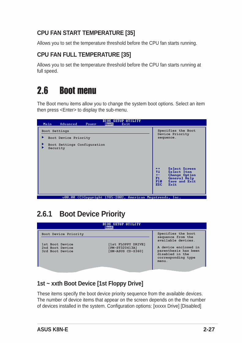
ASUS K8N-E 2-27
2.6 Boot menuThe Boot menu items allow you to change the system boot options. Select an itemthen press <Enter> to display the sub-menu.
2.6.1 Boot Device Priority
1st ~ xxth Boot Device [1st Floppy Drive]
These items specify the boot device priority sequence from the available devices.The number of device items that appear on the screen depends on the the numberof devices installed in the system. Configuration options: [xxxxx Drive] [Disabled]
Boot Settings
Boot Device Priority
Boot Settings ConfigurationSecurity
Boot Device Priority
1st Boot Device [1st FLOPPY DRIVE]2nd Boot Device [PM-ST320413A]3rd Boot Device [SM-ASUS CD-S360]
Specifies the BootDevice Prioritysequence.
Specifies the bootsequence from theavailable devices.
A device enclosed inparenthesis has beendisabled in thecorresponding typemenu.
CPU FAN START TEMPERATURE [35]
Allows you to set the temperature threshold before the CPU fan starts running.
CPU FAN FULL TEMPERATURE [35]
Allows you to set the temperature threshold before the CPU fan starts running atfull speed.

2-28 Chapter 2: BIOS Setup
2.6.2 Hard Disk Drives
1st ~ xxth Drive [XXXXXXXX]
These items specify the boot device priority sequence from the available devices.The number of device items that appear on the screen depends on the the numberof devices installed in the system. Configuration options: [xxxxx Drive] [Disabled]
Hard Disk Drives
1st Drive [PM-ST330620A]2nd Drive [NVIDIA MIRROR 111.]
Specifies the bootsequence from theavailable devices.
2.6.3 Boot Settings Configuration
Boot Settings Configuration
Quick Boot [Enabled]Full Screen Logo [Enabled]AddOn ROM Display Mode [Force BIOS]Bootup Num-Lock [On]PS/2 Mouse Support [Auto]Wait for ‘F1’ If Error [Enabled]Hit ‘DEL’ Message Display [Enabled]Interrupt 19 Capture [Disabled]
Allows BIOS to skipcertain tests whilebooting. This willdecrease the timeneeded to boot thesystem.
Quick Boot [Enabled]
Enabling this item allows the BIOS to skip some Power On Self Tests (POST) whilebooting to decrease the time needed to boot the system. When set to [Disabled],BIOS performs all the POST items. Configuration options: [Disabled] [Enabled]
Full Screen Logo [Enabled]
Allows you to enable or disable the full screen logo display feature. Configurationoptions: [Disabled] [Enabled]
Make sure that the above item is set to [Enabled] if you wish to use the ASUSMyLogo2™ feature.
Add On ROM Display Mode [Force BIOS]
Sets the display mode for option ROM.Configuration options: [Force BIOS] [Keep Current]

ASUS K8N-E 2-29
2.6.4 SecurityThe Security menu items allow you to change the system security settings. Selectan item then press <Enter> to display the configuration options.
Security Settings
Supervisor Password : Not InstalledUser Password : Not Installed
Change Supervisor PasswordChange User PasswordClear User Password
<Enter> to changepassword.<Enter> again todisable password.
Bootup Num-Lock [On]
Allows you to select the power-on state for the NumLock.Configuration options: [Off] [On]
PS/2 Mouse Support [Auto]
Allows you to enable or disable support for PS/2 mouse.Configuration options: [Disabled] [Enabled] [Auto]
Wait for ‘F1’ If Error [Enabled]
When set to Enabled, the system waits for F1 key to be pressed when erroroccurs. Configuration options: [Disabled] [Enabled]
Hit ‘DEL’ Message Display [Enabled]
When set to Enabled, the system displays the message “Press DEL to run Setup”during POST. Configuration options: [Disabled] [Enabled]
Interrupt 19 Capture [Disabled]
When set to [Enabled], this function allows the option ROMs to trap Interrupt 19.Configuration options: [Disabled] [Enabled]
Change Supervisor Password
Select this item to set or change the supervisor password. The SupervisorPassword item on top of the screen shows the default Not Installed. After youhave set a password, this item shows Installed.

2-30 Chapter 2: BIOS Setup
To set a Supervisor Password:
1. Select the Change Supervisor Password item and press <Enter>.
2. From the password box, type a password combination of at least six (6) lettersand/or numbers, then press <Enter>.
3. Confirm the password when prompted.The message “Password Installed” appears after you have successfully setyour password.The Supervisor Password item now shows Installed.
To change the supervisor password, follow the same steps as in setting a userpassword.
To clear the supervisor password, select the Change Supervisor Password thenpress <Enter>. The message “Password Uninstalled” appears.
After you have set a supervisor password, the other items appear to allow you tochange other security settings.
If you forget your BIOS password, you can clear clear it by erasing the CMOSReal Time Clock (RTC) RAM. See section “2.6 Jumpers” for information on howto erase the RTC RAM.
Security Settings
Supervisor Password : InstalledUser Password : Not Installed
Change Supervisor PasswordUser Access Level [Full Access]Change User PasswordClear User PasswordPassword Check [Setup]
Boot Sector Virus Protection [Disabled]
<Enter> to changepassword.<Enter> again todisabled password.
User Access Level (Full Access]
Allows you to select the access restriction to the Setup items. Configurationoptions: [No Access] [View Only] [Limited] [Full Access]
No Access prevents user access to the Setup utility.
View Only allows access but does not allow change to any field.
Limited allows change only to selected fields, such as Date and Time.
Full Access allows viewing and changing all the fields in the Setup utility.

ASUS K8N-E 2-31
Change User Password
Select this item to set or change the user password. The User Password item ontop of the screen shows the default Not Installed. After you have set a password,this item shows Installed.
To set a User Password:
1. Select the Change User Password item and press <Enter>.
2. On the password box that appears, type a password combination of at least six(6) letters and/or numbers, then press <Enter>.
3. Confirm the password when prompted.The message “Password Installed” appears after you have successfully setyour password.The User Password item now shows Installed.
To change the user password, follow the same steps as in setting a user password.
Clear User Password
Select this item if you wish to clear the user password.
Password Check [Setup]
When set to [Setup], BIOS checks for user password when accessing the Setuputility. When set to [Always], BIOS checks for user password both when accessingSetup and booting the system. Configuration options: [Setup] [Always]

2-32 Chapter 2: BIOS Setup
If you attempt to exit the Setup program without saving your changes, theprogram prompts you with a message asking if you want to save your changesbefore exiting. Press <Enter> to save the changes while exiting.
Exit & Save Changes
Once you are finished making your selections, choose this option from the Exitmenu to ensure that the values you selected are saved to the CMOS RAM. Anonboard backup battery sustains the CMOS RAM and stays on even when the PCis turned off. When you select this option, a confirmation window appears. SelectOk to save changes and exit.
2.7 Exit menuThe Exit menu items allow you to load the optimal or failsafe default values for theBIOS items, and save or discard your changes to the BIOS items.
Exit Options
Exit & Save ChangesExit & Discard ChangesDiscard Changes
Load Setup Defaults
Pressing <Esc> does not immediately exit this menu. Select one of the optionsfrom this menu or <F10> from the legend bar to exit.
Exit system setupafter saving thechanges.
F10 key can be usedfor this operation.
Exit & Discard Changes
Select this option only if you do not want to save the changes that you made to theSetup program. If you made changes to fields other than System Date, SystemTime, and Password, the BIOS asks for a confirmation before exiting.
Discard Changes
Allows you to discard the selections you made and restore the previously savedvalues. After selecting this option, a confirmation appears. Select Ok to discard anychanges and load the previously saved values.
Load Setup Defaults
This option allows you to load the default values for each of the parameters on theSetup menus. When you select this option or if you press <F5>, a confirmationwindow appears. Select Ok to load default values. Select Exit and Save Changesor make other changes before saving the values to the non-volatile RAM.

Chapter 3
This chapter describes the contents of thesupport CD that comes with the motherboardpackage.
Software support

3-2 Chapter 3: Software support
3.1 Install an operating systemThis motherboard supports Windows® 2000/XP/2003 Server operating system(OS). Always install the latest OS version and corresponding updates to maximizethe features of your hardware.
3.2 Support CD informationThe support CD that came with the motherboard contains useful software andseveral utility drivers that enhance the motherboard features.
3.2.1 Running the support CDTo begin using the support CD, simply insert the CD into your CD-ROM drive. TheCD automatically displays the Drivers menu if Autorun is enabled in yourcomputer. Click on an item to install.
The contents of the support CD are subject to change at any time withoutnotice. Visit the ASUS website for updates.
If Autorun is NOT enabled in your computer, browse the contents of thesupport CD to locate the file ASSETUP.EXE from the BIN folder. Double-clickthe ASSETUP.EXE to run the CD.
Click an icon to displaymore information
Click an item to install
Motherboard settings and hardware options vary, so use the setup procedurespresented in this chapter for general reference only. Refer to your OSdocumentation for more information.

ASUS K8N-E 3-3
3.2.2 Drivers menuMicrosoft DirectX 9.0 Driver
Installs the Microsoft® DirectX™ 9.0 driver.
Nvidia Chipset Driver Program
Installs the NVIDIA® Chipset drivers for the NVIDIA® nForce™ 3 250Gb chipset.
For Windows® XP users, make sure to install Windows® XP Service Pack 1 orlater to support USB 2.0.
Make Chipset IDE Driver Disk
Creates the NVIDIA® driver disk for Serial ATA and RAID features.
ALC850 Driver
Installs the Realtek® ALC850 audio controller and application.
USB 2.0 Driver
Installs the Universal Serial Bus 2.0 (USB 2.0) driver.
Make sure to install the Microsoft® DirectX™ 9.0 driver before installing theNVIDIA® Chipset drivers.
AMD Cool ‘n’ Quiet Driver
Installs the AMD Cool ‘n’ Quiet!™ Technology driver.

3-4 Chapter 3: Software support
ASUS’ AMD Cool ‘n’ Quiet SoftwareInstalls the AMD Cool ‘n’ Quiet! Technology software.
ASUS PC Probe IIThis smart utility monitors the fan speed, CPU temperature, and system voltages,and alerts you on any detected problems. This utility helps you keep your computerat a healthy operating condition.
Install ASUS UpdateThis program allows you to download the latest version of the BIOS from the ASUSwebsite. Before using the ASUS Update, make sure that you have an Internetconnection so you can connect to the ASUS website. Installing ASUS Update alsoinstalls ASUS Mylogo2™.
Anti-virus Utility
The anti-virus application scans, identifies, and removes computer viruses. Viewthe online help for detailed information.
Acrobat ReaderInstalls the Adobe Acrobat® Reader V5.0. The Acrobat® Reader software is forviewing files saved in Portable Document Format (PDF).
ASUS Screen SaverInstalls the ASUS screen saver.
NVIDIA System UtilityInstalls the NVIDIA® system utility.
3.2.3 Utilities menuThe Utilities menu shows the applications and other software that the motherboardsupports.

ASUS K8N-E 3-5
3.2.4 Manual menuThe Manual menu contains a list of supplementary user manuals. Click an item toopen the manual.
• Most user manual files are in Portable Document Format (PDF). Install theAdobe® Acrobat® Reader from the Utilities menu before opening a usermanual file.
• Some user manuals listed in this menu may not be applicable for thismotherboard model.
3.2.5 ASUS Contact InformationClicking the ASUS Contact Information tab displays as stated. You may also findthis information on the inside front cover of this user guide.

3-6 Chapter 3: Software support
• Make sure to install the AMD Cool ‘n’ Quiet!™ driver and application beforeusing this feature.
• The AMD Cool ‘n’ Quiet!™ Technology feature works only with the AMDheatsink and fan assembly with monitor chip.
3.3 Cool ‘n’ Quiet!™ TechnologyThe motherboard supports the AMD Cool ‘n’ Quiet!™ Technology that dynamicallyand automatically change the CPU speed, voltage and amount of powerdepending on the task the CPU performs.
3.3.1 Enabling Cool ‘n’ Quiet!™ Technology
To enable Cool ‘n’ Quiet!™ technology:
1. Turn on the system and enter BIOS by pressing the <Del> key during thePower On Self-Tests (POST).
2. In the Advanced > CPU Configuration > AMD CPU Cool & QuietConfiguration menu, select the item Cool N’Quiet and set it to Enabled. Seesection “2.4 Advanced Menu” for details.
3. In the Power menu, select the item ACPI 2.0 Support and set it to Yes. Seesection “2.5 Power Menu” for details.
4. Save your changes and exit BIOS Setup.
5. Reboot your computer and set your Power Option Properties depending onyour operating system.
Windows® 2000/XP:
1. From the Windows® 2000/XP operating system, click the Start button. SelectSettings, then Control Panel.
2. Make sure the Control Panel is setto Classic View.
3. Double-click the Display icon in theControl Panel then select theScreen Saver tab.
4. Click the Power... button. Thefollowing dialog box appears.
5. From the Power schemes combolist box, select Minimal PowerManagement.
6. Click OK to effect settings.

ASUS K8N-E 3-7
3.3.2 Launching the Cool ‘n’ Quiet!™ software
The motherboard support CD includes the Cool ‘n’ Quiet!™ software that enablesyou to view your system’s real-time CPU frequency and voltage.
To launch the Cool ‘n’ Quiet!™ program:
1. If you are using Windows® 2000, click the Start button. Select Programs >ASUS > Cool & Quiet > Cool & Quiet.
2. If you are using Windows® XP, click the Start button. Select All Programs >ASUS > Cool & Quiet > Cool & Quiet.
3. The Cool ‘n’ Quiet!™ technology screen appears and displays the current CPUFrequency and CPU Voltage.
Make sure to install the Cool ‘n’ Quiet!™ software from the motherboard supportCD. Refer to section “3.2.3 Utilities” for details.

3-8 Chapter 3: Software support


![Welcome! [dlcdnet.asus.com]dlcdnet.asus.com/pub/ASUS/cdrw/3212a/E960 CRW-3212A 2.2.pdf · following sub-sections describe these technologies in detail. FlextraSpeed™ Technology](https://img.pdfslide.us/doc/110x75/5d663e4a88c9937a098b9ce3/welcome-crw-3212a-22pdf-following-sub-sections-describe-these-technologies.jpg)