Embed Size (px)
Citation preview

K410 / K430 Product Manual

Revision HistoryRevision Date
First release of K400 manual 09/16/2021
Table of ContentsRevision History 1
Table of Contents 2
1 - System Overview 5
1.1 - System Introduction 5
1.2 - Accessories 5
1.3 - Product Specifications 6
1.4 - Exterior Dimensions 8
1.4.1 - Karbon 410 Dimensions (K410) 8
1.4.2 - Karbon 430 Dimensions (K430) 8
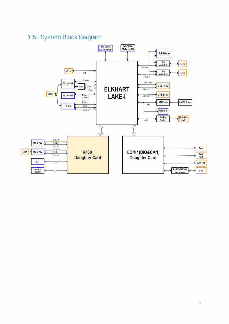
1.5 - System Block Diagram 9
2 - I/O Definitions 10
2.1 - Front I/O Definition 10
Power Button / Power LED 10
SIM Card 10
USB 2.0 11
USB 3.2 11
ModBay COM Expansion 11
ModBay DIO Expansion 11
LED Functionality 12
2.2 - Bottom I/O Definition 13
3-Pin Terminal Power Connector 13
2

CAN Bus 14
LAN 1 & 2 14
DisplayPort 15
2.3 - Top I/O Definition 16
Antenna SMA Ports 16
2.4 - Motherboard Connectors 17
M.2 B-Key 17
M.2 E-Key 17
mPCIe 17
SO-DIMM1 & SO-DIMM2 18
RTC RESET 18
BIOS EEPROM 18
Power Switch Header 18
RTC Battery Header 18
TPM header 18
Onboard Power Header 19
High Speed Daughter Board 19
B-Key 1 19
B-Key 2 20
SIM 1 20
SIM 2 20
RTC Battery 20
3 - Mounting Instructions 21
3.1 - Wall Mounting (MTW101) 21
3.2 - DIN Rail Mounting - Edge (MTD102) 22
3.3 - DIN Rail Mounting - Bottom (MTD103) 23
3.3 - VESA Mounting (VMPL-1056) 24
4 - Power Management 25
4.1 - Wake-Up Events 25
3

4.2 - Protection Circuitry 25
5 - Regulatory Compliance 26
5.1 - FCC 26
5.2 - ISED 26
5.3 - CE 26
5.3.1 - EMC 26
5.3.2 - Safety 26
5.4 - UKCA 26
5.4.1 - EMC 26
5.4.2 - Safety 27
5.5 - Shock and Vibration 27
6 - Appendices 28
6.1 - Appendix A: Power Consumption 28
6.2 - Appendix B: BIOS Manual 30
6.3 - Appendix C: System Thermal Results 31
6.4 - Appendix D: Expansion Port Pinout 32
6.4.1 - M.2 B-Key 32
6.4.2 - M.2 E-Key 33
6.4.4 - mPCIe 34
6.5 - Appendix F: Safety Information 35
6.5.1 - Safe Use and Installation Instructions 35
6.5.2 - Précautions et guide d’installation 36
6.6 - Appendix G: Errata 37
4

1 - System Overview
1.1 - System IntroductionThe Karbon 400 Series packs the power and advanced IoT capabilities of the latest Intel® Atom®x6000E processors (formerly Elkhart Lake) into low profile, rugged and fanless systems built for thechallenges of the IoT Edge.
The Karbon 400 Series was designed to be installed anywhere you need ultra-reliable computingpower. Sensitive internal components are protected from dust, debris, chemicals, and moisture withOnLogic's integrated Hardshell™ Fanless Technology. Its rugged design, -40° to 70°C operatingtemperature range, 9~48 V power input, and the absence of any moving parts dramatically improvethe lifespan and reliability of the system.
1.2 - Accessories● Terminal block kit (Power, CAN bus)● Rubber Feet (4)
If you purchased additional items such as mounting brackets, power supplies, or cables, they will belocated in the system box or within the outer shipping carton.
All drivers and product guides can be found on the corresponding product page. For more informationon accessories and additional features, visit the Karbon series page.
Karbon Series Page: https://www.onlogic.com/computers/rugged/karbon/Karbon 410 Page: https://www.onlogic.com/k410/Karbon 430 Page: https://www.onlogic.com/k430/
5

1.3 - Product SpecificationsKarbon K410 Karbon 430
Dimensions 180 x 123 x 50 mm 180 x 123 x 60 mm
CPU Intel Atom x6211E (2 core, 2 thread, 1.3~3.0 GHz, 6W)Intel Atom x6425E (4 core, 4 thread, 2.0~3.0 GHz, 12W)
Memory 2 SO-DIMM DDR4 3200 up to 32GB total with IBECC support
LAN Controller 2 Intel I210-IT
MotherboardExpansion
M.2 3042/2260/80 B-key (PCIe x2, USB 2.0, SATA, SIM)M.2 2230 E-key (PCIe x1, USB 2.0)mPCIe (PCIe x1, USB 2.0, SATA, SIM)
MotherboardI/O
2 GbE LAN (optional 2 PoE using module)2 USB 3.2 Gen 2 Type-A2 USB 2.0 Type-A1 DisplayPort (DP 1.4 & HDMI 2.0b)3-pin CAN bus3-pin Power input1 Power button1 3FF Micro-SIM (mapped to motherboard mPCIe and M.2)8 LED array (Power, Storage, Ignition, Watchdog, 4 User Configurable)
MotherboardHeaders
TPM 2.0 module headerPoE module headerDC power headerRTC battery holder
DaughterboardExpansion N/A
M.2 3042/52/2260/80 B-key (PCIe x1, USB3.0, USB 2.0, SIM)M.2 2242/60/80 B-key (PCIe x1, USB 3.0,USB 2.0)
DaughterboardI/O N/A 3FF Micro-SIM (mapped to M.2 3042/52)
DaughterboardHeaders N/A 3FF Micro-SIM (mapped to M.2 3042/52)
Voltage Input 9~48 VDC (3-pin Terminal Block with IGN pin)
PowerProtections
Reverse Power Input ProtectionOver Voltage Protection (52.8V)ESD Protection (15kV Air, 8kV Contact)Chassis Grounding Nut
OS Support Windows IoT Enterprise
SpecialFeatures
Automotive Power with Ignition SensingWatchdog TimerPTT and Secure Boot in BIOS
Mounting Wall, DIN rail, VESA
Temperature -40~70°C, Operating
6

-40~85°C, Storage
Humidity 10~95% non-condensing, Operating0~95% non-condensing, Storage
Shock Tested according to IEC 60068-2-27 and MIL-STD-810H Method 516.6
Vibration Tested according to IEC 60068-2-64 and MIL-STD-810H Method 514.6
RegulatoryCertifications
FCC part 15b (Class A), CE, VCCI, RCMMeets requirements of CE Directives for I.T.E. (EMC 2014/30/EU, ErP2009/125/EC, Low Voltage 2014/35/EU, Radio Equipment 2014/53/EU, RoHS 3EU 2015/863, WEEE 2002/96/EC)Meets requirements of IEC 60601-1-2:2014 Medical Electrical EquipmentMeets requirements of CEC Title 20 Appliance Efficiency RegulationsMeets requirements of E-Mark (UNECE Reg. 10, latest revision)Meets requirements of EN 50155 (via testing to EN 50121-3-2)Meets requirements of IEC 60945 Ed. 4 Maritime Navigation andRadiocommunication Equipment and SystemsMeets requirements of IEC 62368-1 Audio/Video, Information AndCommunication Technology Equipment - Part 1: Safety Requirements
7

1.4 - Exterior Dimensions
1.4.1 - Karbon 410 Dimensions (K410)
1.4.2 - Karbon 430 Dimensions (K430)
8
1.5 - System Block Diagram
9

2 - I/O Definitions
2.1 - Front I/O Definition
Power Button & LEDThe front power button can be used to turn on and off the Karbon system. The power button is amomentary contact button with a blue LED backlight used to display the status of the system. Asingle press while the system is on will initiate a graceful shutdown operation from the OS. Pressingand holding the button for 4 seconds while the system is running will cause a hard reset of thesystem. The system can be woken by a single press of the power button from any state.
The LED backlight will indicate the system status. A solid blue light indicates that the system ispowered in the S0 state. A flashing blue light indicates the system is in the sleep state. The LED is offin S5 and deep sleep states.
SIM CardA 3FF Micro-SIM card slot is present on the front panel of the Karbon 400 platform allowing nativesupport for OnLogic Extrovert 4G LTE modules. The SIM signals can be connected to either the mPCIe
10

or M.2 B-Key internal expansion slots. This selection is controlled in BIOS with the default BIOSsetting being mPCIe. Please refer to the BIOS user manual for more information.
The SIM slot is a Push-Push type receptacle. To insert or remove the SIM card from the front panel ofthe Karbon platform, please use a small implement to push the card into the slot until it clicks. Toremove the card, push with a small implement until the card clicks, then pull on the free end of thecard to remove it.
USB 2.0There are two USB 2.0 Type-A ports on the front panel of the K400 platform. These ports are capableof linking at 480Mbps transfer rates.
USB 3.2There are two USB 3.2 Gen 2 Type A ports on the front panel of the K400 platform. These ports arecapable of linking at 10Gbps transfer rates.
ModBay COM ExpansionThe K400 platform supports an optional COM DB9 add-in card (OnLogic MOD109). The serial portmode and voltage between Off/5V/12V on Pin 9 on K400 can be selected in the BIOS configuration.The serial ports support RS-232, RS-422, and RS-485 configurations. Refer to the BIOS manual inAppendix B for configuration instructions.
Pin RS-232 RS-422 RS-485
1 DCD TX- TX-/RX-
2 RX TX+ TX+/RX+
3 TX RX+ NC
4 NC RX- NC
5 GND NC NC
6 NC NC NC
7 RTS NC NC
8 CTS NC NC
9 RI/PWR NC/PWR NC/PWR
ModBay COM DB9 Pinout
ModBay DIO ExpansionThe K410/K430 platform supports an optional Isolated Digital I/O add-in card (OnLogic MOD110).This option allows for integration of the Karbon 400 Series with existing PLC integrations or other
11

digital logic applications. For a complete explanation of features, operating voltages, and safetyinformation, please refer to the DIO expansion information on the OnLogic support site.
https://www.onlogic.com/support/documentation/mod110-dio/
Pin Definition Pin Definition
1 Power 2 GND
3 In0/QEP0A 4 Out0/PWM0
5 In1/QEP0B 6 Out1/PWM1
7 In2/QEP0I 8 Out2/PWM2
9 In3/QEP1A 10 Out3
11 In4/QEP1B 12 Out4
13 In5/QEP1I 14 Out5
15 In6 16 Out6
17 In7 18 Out7
19 CANL 20 CANH
ModBay DIO Pinout
LED Functionality
LED On Off Blink Pulse
HDD - - Internal storagedrive activity -
Power Device is on Device is off Device is asleep -
Automotive Ignition Ignition input todevice is on
Ignition input todevice is off - -
Watchdog - - - -
ConfigurableLED 1-4
UserProgrammable
UserProgrammable
UserProgrammable
UserProgrammable
12
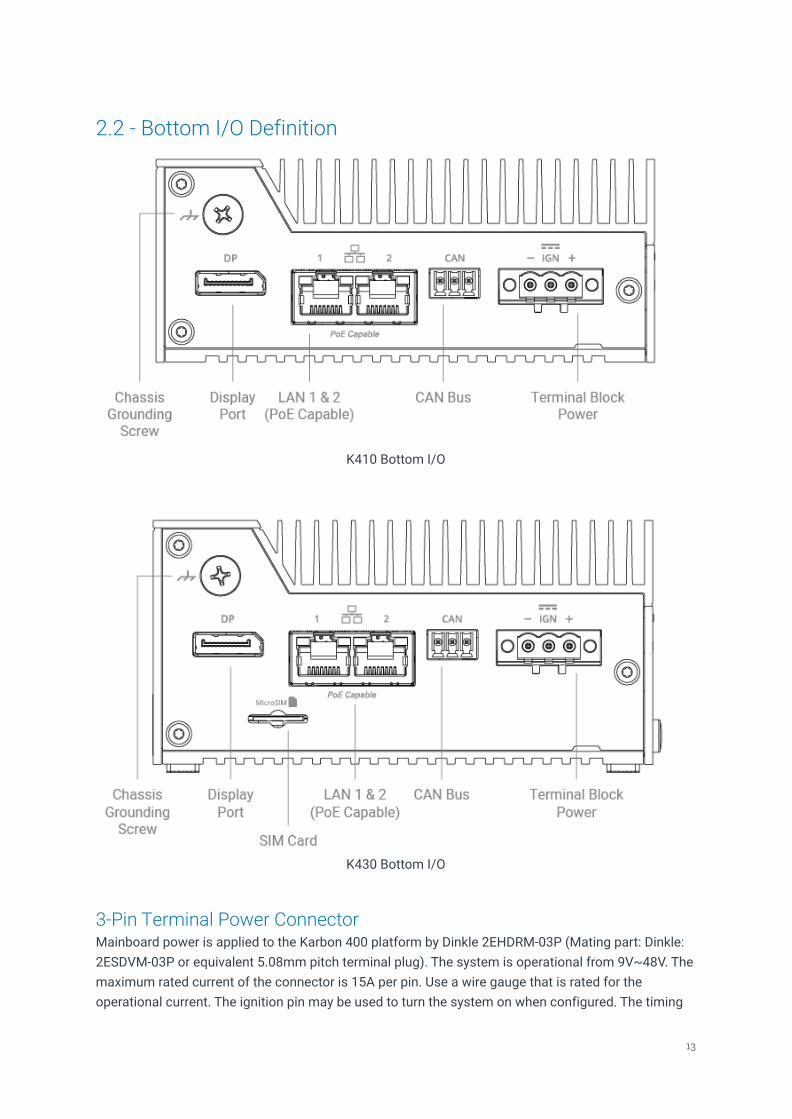
2.2 - Bottom I/O Definition
K410 Bottom I/O
K430 Bottom I/O
3-Pin Terminal Power ConnectorMainboard power is applied to the Karbon 400 platform by Dinkle 2EHDRM-03P (Mating part: Dinkle:2ESDVM-03P or equivalent 5.08mm pitch terminal plug). The system is operational from 9V~48V. Themaximum rated current of the connector is 15A per pin. Use a wire gauge that is rated for theoperational current. The ignition pin may be used to turn the system on when configured. The timing
13

is configurable through the OS, similar to K700/K300 configurations. Please see the OnLogic supportsite for Ignition and timing configuration. See below for on-board connector pinout.
Pin Definition
1 GND
2 Ignition(9-48V)
3 DC Input(9-48V)
Power Input Pinout
CAN BusSupports CAN 2.0 A/B at 100-1000 kbaud via the Programmable Services Engine. Messages may besent/received through the HECI (Host Embedded Controller Interface). A command line interfaceutility for interfacing with the CAN device over HECI is provided, and applications can also interactwith the HECI driver directly. For more information, please refer to our technical documentation on theOnLogic support site.
The internal CAN signals are unterminated; the CAN device should be externally terminated.● 3-pin CAN Bus● Dinkle EC350V-03P terminal block
Pin Definition
1 GND
2 CAN L
3 CAN H
CAN Bus Pinout
LAN 1 & 2There are two LAN Ports on the K400 platform that support up to 1 Gbps link speeds over standardshielded CAT5e or CAT6 cables. The connector is the industry standard RJ45 connector. The LAN linkstate is shown by the two LEDs embedded within the port. The description is included below.
The PoE add-on card option enables Power over Ethernet for both LAN ports. Both ports areconfigured for 802.3atcapabilities. A total power budget of 36W is provided for both ports, such thattwo 802.3af devices may be used, with a single port connected to a 802.3at device as an additionalsupported configuration.
14

LED Color State Function
Link
- Off LAN link notestablished
Green
On LAN linkestablished
Blinking LAN activityoccurring
Speed
- Off 10 Mb/sdata rate
Green On 100 Mb/sdata rate
Yellow On 1000 Mb/sdata rate
LAN Activity Light Definition
DisplayPortThe Karbon 400 platform utilizes Intel’s Integrated processor graphics that power the onboardDisplayPort with support for resolutions up to 4096x2304 at 60Hz. The port also supportsMulti-Stream Transport (MST) which allows for triple independent display output using a certifiedMST hub. The DisplayPort connector supports CEC protocol.
15

2.3 - Top I/O Definition
Antenna SMA PortsThe Karbon 410 and 430 both have four SMA ports for antennas on the top of the system. The Karbon430 includes two additional SMA ports on the front of the system.
16

2.4 - Motherboard ConnectorsThe motherboard is the same for K410 and K430.
M.2 B-KeyAn M.2 B-Key slot on the Karbon 400 motherboard provides support for B-Key form-factor expansioncards. Supported cards include 3042, 2242, 2260, 2280 form-factors. The B-Key connector supportsPCIe Gen 3 x2, USB 3.2 5Gbps, USB 2.0, SATA Gen I (1.5Gbps), SATA Gen II (3.0Gbps), and SATA GenIII (6.0Gbps) devices.
The 3FF Micro SIM card slot is multiplexed to both the M.2 B-Key and mPCIe expansion slot. Therouting can be selected in the BIOS and is set to the mPCIe slot by default. Please refer to the BIOSuser manual (Appendix B) for more information.
A full pinout table for this expansion slot is provided in Appendix D.
M.2 E-KeyAn M.2 E-Key slot on the Karbon 400 motherboard provides support for E-Key form-factor expansioncards. Only 2230 form-factor cards are supported. The E-Key connector supports PCIe Gen 3 x1 andUSB 2.0 devices. A full pinout table for this expansion slot is provided in Appendix D.
mPCIeA mPCIe slot is present on the Karbon 400 motherboard to allow support for mini-PCIe form-factorexpansion cards. Full length cards and half-length cards (with an adapter) are supported. The mPCIe
17

connector supports PCIe Gen 3 x1 and USB 2.0 devices. A full pinout table for this expansion slot isprovided in Appendix D.
The 3FF Micro-SIM card slot is multiplexed to both the M.2 B-Key and mPCIe expansion slot. Therouting can be selected in the BIOS and is set to the mPCIe slot by default. Please refer to the BIOSuser manual (Appendix B) for more information.
SO-DIMM1 & SO-DIMM2
Karbon 400 has two onboard DDR4 SO-DIMM slots:
● Maximum Capacity: 32GB DDR4-3200 total using two 16GB SO-DIMM modules● Channel configuration: 1 DIMM Per Channel (DPC) - 2 Channels● In Band ECC Support (IBECC)
RTC RESETThe snap dome tact switch behind the power button on the Karbon 400 motherboard may be used toclear the CMOS settings in the BIOS. Remove external power to the system before clearing the CMOS.Removing the RTC battery is not an accepted method for clearing BIOS settings.
BIOS EEPROMIf the BIOS needs to be updated, please refer to Appendix B for reflashing instructions.
Power Switch HeaderThe on-board power switch header can be used to control the power state of the Karbon 400 platformin parallel with the front panel power button. Mating power switch cables should be a twisted-pair wirewith floating shield to assure proper immunity to EMI/RFI. The mating connector is a standard2.54mm female header. It is recommended to keep wires at less than 3 meters in length. Switchesmust be momentary contact type only.
RTC Battery HeaderThe RTC battery on the Karbon 400 platform is used to retain BIOS CMOS settings and maintain thereal-time clock for the system. If the RTC battery is low, CMOS settings will not be retained and youmay receive an alert in the operating system. Replacement batteries should be a UL listed typeCR2032 3V cell.
TPM headerKarbon 400 features an onboard TPM (Trusted Platform Module) header. It supports OnLogic’swide-temperature TPM 2.0 module (OnLogic TPM01). This gives the option to have a dedicatedsecure module to secure the system through cryptographic keys.
18

Onboard Power HeaderAn onboard connector is provided for power to internal expansion cards. The connector is a JST2.0mm PH series connector (pn: B4B-PH-K-S). A suitable mating connector from the same seriesshould be used. The Pinout is provided below. The maximum operating current per pin is 2A. Theheader is only powered while the system is in the S0 operating state.
Pin Function
1 5V
2 GND
3 GND
4 12V
High Speed Daughter BoardThe Karbon 430 system supports an additional daughter board for additional high speed storage andconnectivity options. The daughter board is pictured below.
M.2 B-Key 1The upper B-Key slot is provided to allow support for B-Key form-factor PCIe and USB expansioncards. Supported cards include 3042, 3052, 2260, 2280 form-factors. The B-Key connector on theKarbon expansion card supports PCIe Gen 3 x1, USB 3.2 5Gbps, USB 2.0 devices. B-Key SATA drivesare not electrically compatible with this slot.
19

There are two 3FF SIM slots on the daughter board to support networking capabilities. One SIM slot isexternally accessible, with the other accessed on the bottom of the HSIO card.
M.2 B-Key 2The lower B-Key slot is provided to allow support for B-Key form-factor PCIe and USB expansioncards. Supported cards include 2042, 2260, and 2280 form-factors. The B-Key connector on theKarbon 400 expansion card supports PCIe Gen 3 x1, USB 3.2 5Gbps, USB 2.0 devices. B-Key SATAdrives are not electrically compatible with this port.
SIM 1The externally accessible 3FF SIM 1 slot is provided for networking capabilities on the B-Key 1 slot.
SIM 2The internally accessible 3FF SIM 2 slot is provided for networking capabilities on the B-Key 1 slot.This slot is on the bottom side of the Expansion card and is only accessible by removing thedaughterboard from the chassis.
RTC BatteryThe RTC battery on the Karbon 400 expansion card is provided for redundancy with the main CMOSbattery to retain BIOS CMOS settings and maintain the real-time clock for the system. If the RTCbattery is low, CMOS settings will not be retained and you may receive an alert in the operatingsystem. Replacement batteries should be a UL listed type CR2032 3V cell.
20

3 - Mounting Instructions
3.1 - Wall Mounting (MTW101)
Step 1: Attach wall mounting brackets to the chassis using the provided screws. To assemble, locatethe four holes in the chassis that line up to the two countersunk holes in each wall mount bracket.
Screw type: M3x0.5 FH 120 DegreeLength: 4 mm
Step 2: Take care to ensure that the brackets are oriented correctly and that the part of the brackets incontact with the mounting surface is positioned away from the system to ensure a small air gap ismaintained between the mounting surface and the system. Install the four supplied screws.
Step 3: Fasten system to the mounting surface (hardware not provided). The mounting bracketsystems are required to secure 3x the hanging weight of the computer system. The mating substratemust be capable of maintaining the same rating.
21

3.2 - DIN Rail Mounting - Edge (MTD102)
Step 1: Attach DIN Clip to the back of the chassis using the provided screws. To assemble, locate thetwo holes in the back of the chassis that line up to the two countersunk holes on the DIN clip.
Screw type: M3x0.5 FH 120 DegreeLength: 6 mm
Step 2: The orientation of the DIN clip is interchangeable between the two options. Determine thepreferred orientation of the system and install the screws to the DIN clip accordingly.
Step 3: Install the system onto a DIN rail in the desired location.
22
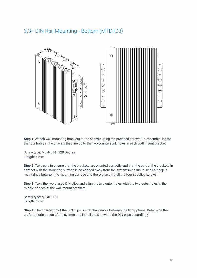
3.3 - DIN Rail Mounting - Bottom (MTD103)
Step 1: Attach wall mounting brackets to the chassis using the provided screws. To assemble, locatethe four holes in the chassis that line up to the two countersunk holes in each wall mount bracket.
Screw type: M3x0.5 FH 120 DegreeLength: 4 mm
Step 2: Take care to ensure that the brackets are oriented correctly and that the part of the brackets incontact with the mounting surface is positioned away from the system to ensure a small air gap ismaintained between the mounting surface and the system. Install the four supplied screws.
Step 3: Take the two plastic DIN clips and align the two outer holes with the two outer holes in themiddle of each of the wall mount brackets.
Screw type: M3x0.5 PHLength: 6 mm
Step 4: The orientation of the DIN clips is interchangeable between the two options. Determine thepreferred orientation of the system and install the screws to the DIN clips accordingly.
23

3.3 - VESA Mounting (VMPL-1056)
Step 1: Attach VESA mounting plate to the chassis using the provided screws. Align the four holes onthe VESA mounting plate with the corresponding holes on the chassis bottom.
Screw type: M3x0.5 FH 120 DegreeLength: 4 mm
Step 2: Attach system to a corresponding VESA MIS-D 75 or MIS-D 100 mounting pattern using thesupplied M4x0.7 slotted standoffs.
24

4 - Power Management
4.1 - Wake-Up EventsThe Karbon 400 platform supports multiple power states. The wake-up events can be configured inthe BIOS. This section describes the supported power management functions and gives informationon protection circuitry for power adapters.
Wake-Up Event From ACPI State Comments
Power Button Low PowerShutdown, S5, S3
LAN S5, S3 Must be enabled in BIOS
USB S3
RTC Wake set by BIOS S5, S3 Must be enabled in BIOS
RTC Wake set by OS S3 Must be enabled in OS
Ignition Low PowerShutdown, S5, S3 Must be enabled in OS
4.2 - Protection CircuitryParameter Value
Nominal operating voltage (Rated DC value of input) 9~48V
Undervoltage protection trip DC level (system turns off) 6.9V
Maximum safe DC voltage (system not damaged) 57V
Ignition pin operating voltage 8~48V
Ignition pin max safe voltage (system not damaged) 57V
The specified DC levels are the absolute maximum values for function and safety of the system. Theprotection circuitry allows for brief transient voltages above these levels without the system turningoff or being damaged. A transient voltage suppressor on the power input allows momentaryexcursions above stated limits. For input power consumption and current see Appendix A.
The Karbon 400 platform enables a unique low power state for use in automotive or battery poweredapplications. When enabled, the total power draw for the system is less than 10mA, making thissolution ideal for systems requiring ultra-low quiescent power draw. This setting must be enabledfrom the OS similar to ignition settings. The system may be woken by either the power button or theignition pin.
25

5 - Regulatory Compliance
CEThe computer system was evaluated for medical, IT equipment, automotive, maritime and railwayEMC standards as a class A device. The computer complies with the relevant IT equipment directivesfor the CE mark. Modification of the system may void the certifications. Testing included: EN 55032,EN 55035, EN 60601-1, EN 62368-1, EN 50121-3-2, and UN Regulation No. 10 ISO 17650-2.
FCC StatementThis device complies with part 15 of the FCC rules as a Class A device. Operation is subject to thefollowing two conditions: (1) this device may not cause harmful interference and (2) this device mustaccept any interference received, including interference that may cause undesired operation.
ISED (Innovation, Science and Economic Development Canada)This device complies with Industry Canada license-exempt RSS standard(s). Operation is subject tothe following two conditions: (1) this device may not cause interference, and (2) this device mustaccept any interference, including interference that may cause undesired operation of the device.
Le présent appareil est conforme aux CNR d'Industrie Canada applicables aux appareils radioexempts de licence. L'exploitation est autorisée aux deux conditions suivantes : (1) l'appareil ne doitpas produire de brouillage, et (2) l'utilisateur de l'appareil doit accepter tout brouillage radioélectriquesubi, même si le brouillage est susceptible d'en compromettre le fonctionnement.
CAN ICES-003(A) / NMB-003(A)
UKCAThe computer system was evaluated for medical, IT equipment, automotive, maritime and railwayEMC standards as a class A device. The computer complies with the relevant IT equipment directivesfor the UKCA mark.
26

6 - Appendices
6.1 - Appendix A: Power ConsumptionThe power consumption of the K410 and K430 was measured for various system configurations,workloads, and power states at both 9V and 48V system input voltages. Tests were performed usingBurnintest v9.0 build 1012 to stress system components with and without graphics enabled. The buildconfigurations and power consumption are listed in the tables below.
The configurations below are using representative samples of internal devices, the specificcomponents mentioned below may vary from the devices provided by OnLogic. The powerconsumption for each system configuration is record below
SystemComponent Config 1 Low K410 Config 2 Mid K410 Config 3 High K430
CPU Atom x6211E 2C/2T/6W Atom x6425E 4C/4T/12W Atom x6425E 4C/4T/12W
Memory 8GB DDR4 So-DIMM 2x 16GB DDR4 So-DIMM 2x 16GB DDR4 So-DIMM
LAN 2x Intel I210 2x Intel I210 2x Intel I210
Storage #1mPCIe SATA none 128Gb SATA 128Gb SATA
Storage #2M.2 B-Key 128Gb SATA 1TB NVMe 1TB NVMe
M.2 E-Key none Intel 9260 Intel 9260
COM1 Loopback test Loopback test Loopback test
COM2 Loopback test Loopback test Loopback test
ExpansionM.2 B-Key #1 N/A N/A 512GB NVMe
ExpansionM.2 B-Key #2 N/A N/A 512GB NVMe
USB Loopback test (all ports) Loopback test (all ports) Loopback test (all ports)
OS WIndows 10 Pro 64 Bit WIndows 10 Pro 64 Bit WIndows 10 Pro 64 Bit
BIOS Version A049 A049 A049
27
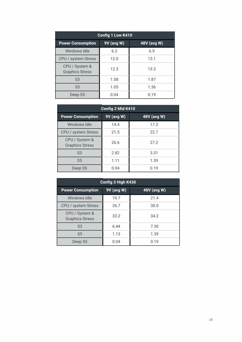
Config 1 Low K410
Power Consumption 9V (avg W) 48V (avg W)
Windows Idle 6.3 6.9
CPU / system Stress 12.0 13.1
CPU / System &Graphics Stress 12.3 13.3
S3 1.58 1.87
S5 1.05 1.36
Deep S5 0.04 0.19
Config 2 Mid K410
Power Consumption 9V (avg W) 48V (avg W)
Windows Idle 14.4 17.3
CPU / system Stress 21.5 22.7
CPU / System &Graphics Stress 26.6 27.2
S3 2.82 3.31
S5 1.11 1.39
Deep S5 0.04 0.19
Config 3 High K430
Power Consumption 9V (avg W) 48V (avg W)
Windows Idle 19.7 21.4
CPU / system Stress 26.7 30.0
CPU / System &Graphics Stress 33.2 34.2
S3 6.44 7.30
S5 1.13 1.39
Deep S5 0.04 0.19
28

6.2 - Appendix B: BIOS ManualFor a detailed overview of the BIOS screens and individual settings, please refer to the OnLogicsupport site. Instructions for updating the BIOS can also be found on the support site. Please refer tothe link below for detailed instructions.
https://www.onlogic.com/support/documentation/k400-technical-resources
29

6.3 - Appendix C: System Thermal ResultsThe thermal performance of the Karbon 400 platform was validated by loading the system to simulateworkloads in excess of expected workloads. That is to say, the system was loaded to run at its fullrated TDP (12W) while also simultaneously stressing memory and storage at different set pointsacross the system's rated operating temperature range for hours on end. System performance wasreviewed to look for any indication of performance issues or for components operating outside oftheir rated temperature range. Samples of data collected during one of these thermal evaluations forthis platform are shown below. The sample data was collected during a test of the K410 chassis withthe x6425E processor, 64 GB of DDR4 RAM and an NVMe storage drive. Of note in these results is thefact that no significant drops (10% or more) were observed in core frequency or package power.There were no indications of any throttling in the system throughout the entirety of the test.
30

6.4 - Appendix D: Expansion Port Pinout
6.4.1 - M.2 B-KeyPin Function Function Pin1 CONFIG_3 3.3V 23 GND 3.3V 45 GND FULL_CARD_POWER_OFF# 67 USB 2.0 D+ W_DISABLE1# 89 USB 2.0 D- NC 10
11 GND KEY 1213 KEY KEY 1415 KEY KEY 1617 KEY KEY 1819 KEY NC 2021 CONFIG_0 NC 2223 NC NC 2425 NC GPIO_10/W_DISABLE2# 2627 GND NC 2829 PERn1/USB3.1-Rx- UIM-RESET 3031 PERp1/USB3.1-Rx+ UIM_CLK 3233 GND UIM_DATA 3435 PETn1/USB3.1-Tx- UIM_PWR 3637 PETp1/USB3.1-Tx+ NC 3839 GND NC 4041 PERn0/SATA-B+ NC 4243 PERp0/SATA-B- NC 4445 GND NC 4647 PETn0/SATA-A- NC 4849 PETp0/SATA-A+ PERST# 5051 GND CLKREQ# 5253 REFCLKn PEWAKE# 5455 REFCLKp NC 5657 GND NC 5859 NC NC 6061 NC NC 6263 NC NC 6465 NC SIM_DETECT 6667 RESET_N SUSCLK 6869 CONFIG_1 3.3V 7071 GND 3.3V 7273 GND 3.3V 7475 CONFIG_2
31

6.4.2 - M.2 E-KeyPin Function Function Pin1 GND 3.3 V 23 USB_D+ 3.3 V 45 USB_D- NC 67 GND PCM_CLK 89 RESERVED CNV_RF_RESET#_R 10
11 RESERVED BT_PCMIN 1213 GND BT_PCMOUT 1415 RESERVED NC 1617 RESERVED GND 1819 GND NC 2021 RESERVED RESERVED 2223 RESERVED KEY 2425 KEY KEY 2627 KEY KEY 2829 KEY KEY 3031 KEY RESERVED 3233 GND RESERVED 3435 PETp0 RESERVED 3637 PETn0 RESERVED 3839 GND RESERVED 4041 PERp0 RESERVED 4243 PERn0 RESERVED 4445 GND RESERVED 4647 REFCLKp0 RESERVED 4849 REFCLKn0 SUSCLK(32kHz) 5051 GND PERST0# 5253 CLKREQ0# W_DISABLE2# 5455 PEWAKE0# W_DISABLE1# 5657 GND NC 5859 RESERVED NC 6061 RESERVED NC 6263 GND RESERVED 6465 RESERVED NC 6667 RESERVED NC 6869 GND NC 7071 RESERVED 3.3V 7273 RESERVED 3.3V 7475 GND
32

6.4.4 - mPCIePin Function Function Pin1 WAKE# 3.3V 23 NC GND 45 NC 1.5V 67 CLKREQ# UIM_PWR 89 GND UIM_DATA 10
11 REFCLK- UIM_CLK 1213 REFCLK+ UIM_RESET 1415 GND UIM_SPU 1617 KEY KEY 1817 NC GND 1819 NC W_DISABLE1# 2021 GND PERST# 2223 PERn0 3.3V 2425 PERp0 GND 2627 GND 1.5V 2829 GND SMB_CLK 3031 PETn0 SMB_DATA 3233 PETp0 GND 3435 GND USB 2.0_D- 3637 GND USB 2.0_D+ 3839 3.3V GND 4041 3.3V NC 4243 GND NC 4445 NC NC 4647 NC 1.5V 4849 NC GND 5051 W_DISABLE2# 3.3V 52
33

6.5 - Appendix F: Safety InformationDo not open or modify the device. The device uses components that comply with FCC and CEregulations. Modification of the device may void these certifications.
Ne pas ouvrir ni modifier l'appareil. L'appareil utilise des composants conformes aux réglementationsFCC et CE. La modification de l'appareil peut annuler ces certifications.
6.5.1 - Safe Use and Installation Instructions1. Install the device securely. Be careful handling the device to prevent injury and do not drop.2. Wall or ceiling mounting the device requires use of a mounting plate or bracket. The plate or
bracket must be of metal construction and have a minimum thickness of 1mm.3. Use M3x0.5mm Flat Head screws to attach mounting plate or mounting brackets to threaded
holes on bottom or rear of chassis. Screws should be a minimum length of 4mm. Add 1mmof screw length for every mm of additional thickness of plate or bracket beyond 1.5mm.
4. Ambient operating temperature must be between-40 °C to 70 °C with a non-condensingrelative humidity of 10-90%.
5. The device can be stored at temperatures between -40 °C to 85 °C.6. Keep the device away from liquids and flammable materials.7. Do not clean the device with liquids. The chassis can be cleaned with a cloth.8. Allow at least 2 inches of space around all sides of the device for proper cooling. If the device
is mounted to a vertical surface then recommended device orientation is so that heatsink finsallow air to rise unobstructed. Alternative orientations may result in reduced operationaltemperature range.
9. This device is intended for indoor operation only.10. Use UL Listed external power supply with rated output 9-48Vdc11. Install the device only with shielded network cables.12. Only use SAE approved cables for automotive installation.13. The installer should be experienced in aftermarket installation and familiar with general
practices for installing electronics devices in vehicles.14. The device should not be installed in the driver’s area of a vehicle.15. The device should be mounted in accordance with accepted aftermarket practices and
materials for vehicle installation.16. Only use UL Listed connectors for connection to automotive fuse panels.17. Service and repair of the device must be done by qualified service personnel. This includes,
but is not limited to, replacement of the CMOS battery. Replacement CMOS battery must beof the same type as the original.
18. Proper disposal of CMOS batteries must comply with local governance.
WARNING: There is danger of explosion if the CMOS battery is replaced incorrectly.Disposal of battery into fire or a hot oven, or mechanically crushing or cutting of a batterycan result in an explosion.
34

6.5.2 - Précautions et guide d’installation1. Installez l’appareil en toute sécurité. Soyez prudent lors de la manipulation de l'appareil pour
éviter les blessures et ne pas faire tomber.2. Le montage au mur ou au plafond nécessite l’utilisation d’une plaque de montage ou d’un
support. La plaque ou le support doit être en métal et doit avoir une épaisseur minimale de 1mm.
3. Utilisez des vis à tête plate M3x0,5mm pour fixer la plaque de montage ou les supports auxtrous filetés situés au bas ou à l'arrière du châssis. Les vis doivent avoir une longueurminimale de 4 mm. Ajoutez 1 mm de longueur de vis pour chaque mm d'épaisseursupplémentaire de plaque ou de support dépassant 1,5 mm.
4. La plage de températures de fonctionnement doit être de -40 °C à 70 °C avec une humiditérelative de 10 à 90% sans condensation. La température de fonctionnement dépend du choixdu composant, y compris de l'adaptateur d'alimentation. Voir le tableau 1 ci-dessous pour ledéclassement.
5. La plage de températures de stockage doit être de -40 °C à 85 °C.6. Gardez l'appareil à l'écart des liquides et des matières inflammables.7. Ne nettoyez pas l'appareil avec des liquides. Le châssis peut être nettoyé avec un chiffon.8. Laissez au moins 5 cm d'espace autour de tous les côtés de l'appareil pour un
refroidissement correct. Si l’appareil est monté sur une surface verticale, l’orientationrecommandée est telle que les ailettes du dissipateur de chaleur permettent à l’air de montersans obstruction. Les orientations alternatives peuvent entraîner une réduction de la plage detempérature de fonctionnement.
9. Cet appareil est conçu uniquement pour une utilisation en intérieur.10. Utilisez une alimentation externe listée UL avec une sortie nominale de 9-48Vdc.11. Installez l’appareil uniquement avec des câbles réseau blindés.12. Utilisez uniquement des câbles approuvés par SAE pour l'installation automobile.13. L'installateur doit être expérimenté dans l'installation après-vente et familiarisé avec les
pratiques générales d'installation de dispositifs électroniques dans les véhicules.14. L'appareil ne doit pas être installé dans la zone du conducteur d'un véhicule.15. L'appareil doit être monté conformément aux pratiques et aux matériaux acceptés du marché
secondaire pour l'installation du véhicule.16. Utilisez uniquement des connecteurs homologués UL pour la connexion aux panneaux de
fusibles automobiles.17. L'entretien et la réparation de l'appareil doivent être effectués par du personnel qualifié. Cela
inclut, sans toutefois s'y limiter, le remplacement de la batterie CMOS. La batterie CMOS deremplacement doit être du même type que l’originale.
18. La mise au rebut des batteries usagées doit être réalisée conformément aux réglementationsenvironnementales.
ATTENTION: Il existe un risque d'explosion si la pile CMOS n'est pas remplacéecorrectement. La mise au rebut de la batterie au feu ou dans un four chaud, ou l'écrasementou la coupure mécanique d'une batterie peut entraîner une explosion.
35

6.6 - Appendix G: Errata
FE-1: RS422 and RS485 Require SerCx2
Overview
Category: DriversRevision(s) Affected: All release hardwareSeverity: LowStatus: ConfirmedRevision Resolved: None
Description
Configuring the system to use RS422 or RS485 serial modes on Windows requires using theSerCx2.sys driver framework. Most existing serial utilities only support the Serial.sys driverframework, requiring the use of Windows APIs to use the RS422/485 serial device.
RS232 serial mode uses the Serial.sys driver framework.
Workaround
A UART Sub-Device driver is available for download, and provides a mapping layer to theSerial.sys driver framework. This driver does not support setting the DTR/DTS hardwarelines, which may result in compatibility issues with some software packages, includingPuTTy.
Resolution
There are no planned changes to the serial framework.
36