Embed Size (px)
Citation preview

Total solder points: 88 + 68 + 367 Difficulty level: beginner 1 2 3 4 5⌧ advanced
Remote controlled car alarm
ILLUSTRATED ASSEMBLY MANUAL H3511IP-2
K3511K3511
2
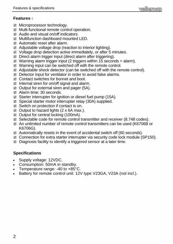
Features :
Microprocessor technology. Multi-functional remote control operation. Audio and visual on/off indicators. Multifunction dashboard mounted LED. Automatic reset after alarm. Adjustable voltage drop (reaction to interior lighting). Voltage drop detection active immediately, or after 5 minutes. Direct alarm trigger input (direct alarm after triggering). Warning alarm trigger input (2 triggers within 15 seconds = alarm). Warning input can be switched off with the remote control. Adjustable shock detector (can be switched off with the remote control). Detector input for ventilator in order to avoid false alarms. Contact switches for bonnet and boot. Internal siren for on/off signal and alarm. Output for external siren and pager (5A). Alarm time: 30 seconds. Starter interrupter for ignition or diesel fuel pump (15A). Special starter motor interrupter relay (30A) supplied. Switch on protection if contact is on. Output to hazard lights (2 x 6A max.). Output for central locking (100mA). Selectable code for remote control transmitter and receiver (8.748 codes). An unlimited number of remote control transmitters can be used (K6706B or
K6706G). Automatically resets in the event of accidental switch off (60 seconds). Connection for extra starter interrupter via security code lock module (SP150). Diagnosis facility to identify a triggered sensor at a later time.
Specifications
• Supply voltage: 12VDC. • Consumption: 50mA in standby. • Temperature range: -40 to +85°C. • Battery for remote control unit: 12V type V23GA, V23A (not incl.).
Features & specifications

3
Assembly hints
1. Assembly (Skipping this can lead to troubles ! ) Ok, so we have your attention. These hints will help you to make this project successful. Read them carefully. 1.1 Make sure you have the right tools: • A good quality soldering iron (25-40W) with a
small tip. • Wipe it often on a wet sponge or cloth, to keep it clean; then apply solder to
the tip, to give it a wet look. This is called ‘thinning’ and will protect the tip, and enables you to make good connections. When solder rolls off the tip, it needs cleaning.
• Thin raisin-core solder. Do not use any flux or grease. • A diagonal cutter to trim excess wires. To avoid injury when cutting
excess leads, hold the lead so they cannot fly towards the eyes. • Needle nose pliers, for bending leads, or to hold compo-
nents in place. • Small blade and Phillips screwdrivers. A basic range
is fine.
For some projects, a basic multi-meter is required, or might
be handy 1.2 Assembly Hints : ⇒ Make sure the skill level matches your experience, to avoid disappointments. ⇒ Follow the instructions carefully. Read and understand the entire step before you
perform each operation. ⇒ Perform the assembly in the correct order as stated in this manual ⇒ Position all parts on the PCB (Printed Circuit Board) as shown on the drawings. ⇒ Values on the circuit diagram are subject to changes. ⇒ Values in this assembly guide are correct* ⇒ Use the check-boxes to mark your progress. ⇒ Please read the included information on safety and customer service * Typographical inaccuracies excluded. Always look for possible last minute manual updates, indicated as ‘NOTE’ on a separate leaflet.
0.000
4
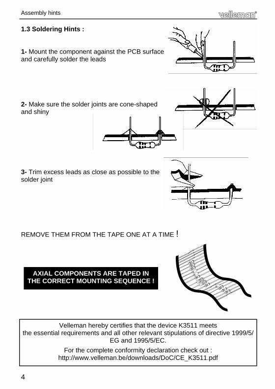
1.3 Soldering Hints :
1- Mount the component against the PCB surface and carefully solder the leads
2- Make sure the solder joints are cone-shaped and shiny
3- Trim excess leads as close as possible to the solder joint
REMOVE THEM FROM THE TAPE ONE AT A TIME !
AXIAL COMPONENTS ARE TAPED IN THE CORRECT MOUNTING SEQUENCE !
Velleman hereby certifies that the device K3511 meets the essential requirements and all other relevant stipulations of directive 1999/5/
EG and 1995/5/EC.
For the complete conformity declaration check out : http://www.velleman.be/downloads/DoC/CE_K3511.pdf
Assembly hints
5
Before mounting the components to the PCB it must first be checked that the PCB fits in the housing. Be careful of the small notch next to LD1. Should it not fit the edge of the PCB can be sanded down with fine sandpaper.
The car alarm consist of three PCB’s, 1 for the remote control transmitter, 1 for the receiver and 1 for the main PCB.
The receiver PCB is fitted to the main PCB.
Tip: The pictures on the packaging can be used as a guideline. However, due to possible changes it is not 100% reliable.
IMPORTANT
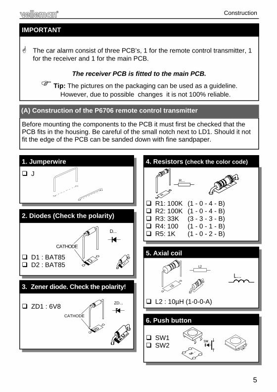
(A) Construction of the P6706 remote control transmitter
J
1. Jumperwire
D1 : BAT85 D2 : BAT85
2. Diodes (Check the polarity)
CATHODE
D...
ZD1 : 6V8
3. Zener diode. Check the polarity!
CATHODE
ZD...
R1: 100K (1 - 0 - 4 - B) R2: 100K (1 - 0 - 4 - B) R3: 33K (3 - 3 - 3 - B) R4: 100 (1 - 0 - 1 - B) R5: 1K (1 - 0 - 2 - B)
4. Resistors (check the color code)
R...
L2 : 10µH (1-0-0-A)
5. Axial coil
L2
L...
SW1 SW2
6. Push button
Construction
6
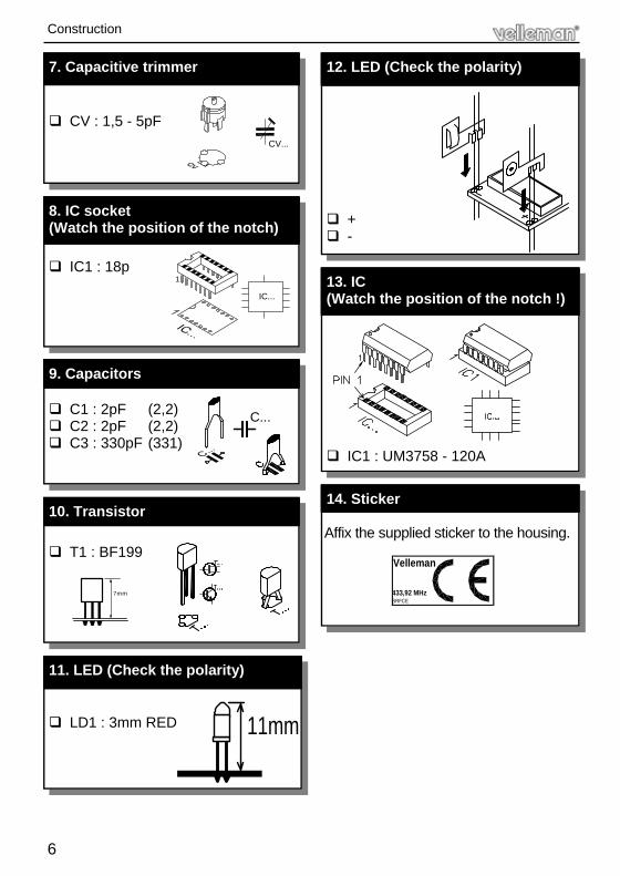
LD1 : 3mm RED
11. LED (Check the polarity)
CV : 1,5 - 5pF
7. Capacitive trimmer
CV...
IC1 : 18p
8. IC socket (Watch the position of the notch)
IC...
1
C1 : 2pF (2,2) C2 : 2pF (2,2) C3 : 330pF (331)
9. Capacitors
C...
T1 : BF199
10. Transistor
7mm
11mm
+ -
12. LED (Check the polarity)
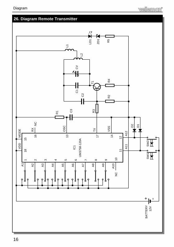
IC1 : UM3758 - 120A
13. IC (Watch the position of the notch !)
Affix the supplied sticker to the housing.
14. Sticker
Velleman
SRFCE433,92 MHz
Construction
7
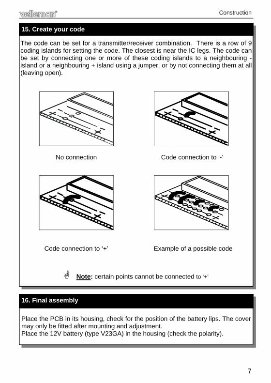
The code can be set for a transmitter/receiver combination. There is a row of 9 coding islands for setting the code. The closest is near the IC legs. The code can be set by connecting one or more of these coding islands to a neighbouring - island or a neighbouring + island using a jumper, or by not connecting them at all (leaving open).
Note: certain points cannot be connected to ‘+’
15. Create your code
No connection Code connection to ‘-’
Code connection to ‘+’ Example of a possible code
Place the PCB in its housing, check for the position of the battery lips. The cover may only be fitted after mounting and adjustment. Place the 12V battery (type V23GA) in the housing (check the polarity).
16. Final assembly
Construction
8
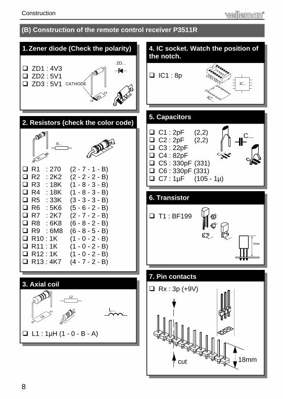
(B) Construction of the remote control receiver P3511R
ZD1 : 4V3 ZD2 : 5V1 ZD3 : 5V1
1. Zener diode (Check the polarity)
CATHODE
ZD...
R1 : 270 (2 - 7 - 1 - B) R2 : 2K2 (2 - 2 - 2 - B) R3 : 18K (1 - 8 - 3 - B) R4 : 18K (1 - 8 - 3 - B) R5 : 33K (3 - 3 - 3 - B) R6 : 5K6 (5 - 6 - 2 - B) R7 : 2K7 (2 - 7 - 2 - B) R8 : 6K8 (6 - 8 - 2 - B) R9 : 6M8 (6 - 8 - 5 - B) R10 : 1K (1 - 0 - 2 - B) R11 : 1K (1 - 0 - 2 - B) R12 : 1K (1 - 0 - 2 - B) R13 : 4K7 (4 - 7 - 2 - B)
2. Resistors (check the color code)
R...
L1 : 1µH (1 - 0 - B - A)
3. Axial coil L2
L...
IC1 : 8p
4. IC socket. Watch the position of the notch.
IC...
1
C1 : 2pF (2,2) C2 : 2pF (2,2) C3 : 22pF C4 : 82pF C5 : 330pF (331) C6 : 330pF (331) C7 : 1µF (105 - 1µ)
5. Capacitors
C...
T1 : BF199
6. Transistor
7mm
Rx : 3p (+9V)
7. Pin contacts
18mm cut
Construction
9
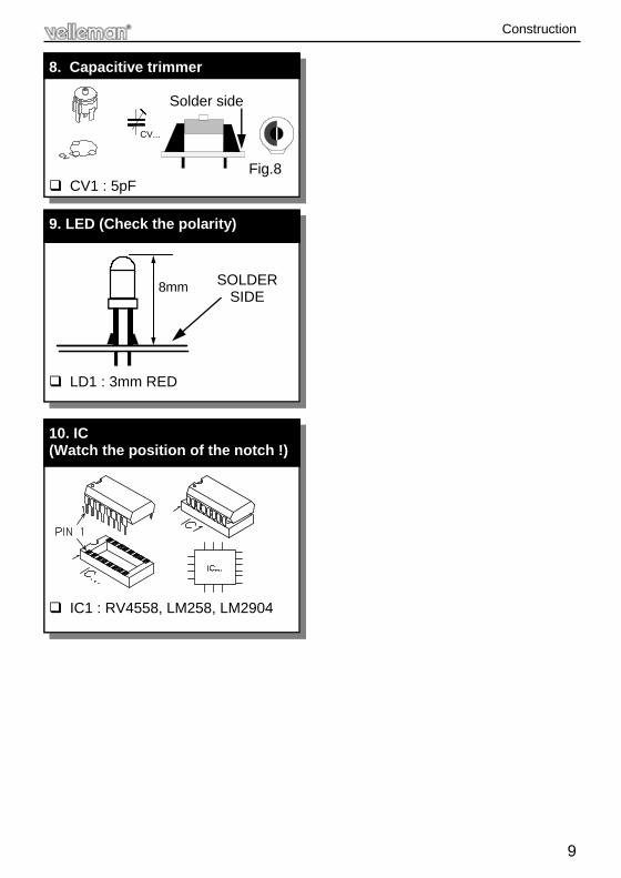
Solder side
Fig.8 CV1 : 5pF
8. Capacitive trimmer
CV...
SOLDER SIDE
LD1 : 3mm RED
9. LED (Check the polarity)
8mm
IC1 : RV4558, LM258, LM2904
10. IC (Watch the position of the notch !)
Construction
10
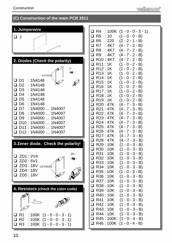
(C) Construction of the main PCB 3511
J
1. Jumperwire
ZD1 : 2V4 ZD2 : 5V1 ZD3 : 18V ZD4 : 18V ZD5 : 18V
3. Zener diode. Check the polarity!
D1 : 1N4148 D2 : 1N4148 D3 : 1N4148 D4 : 1N4148 D5 : 1N4148 D6 : 1N4148 D7 : 1N4000 … 1N4007 D8 : 1N4000 … 1N4007 D9 : 1N4000 … 1N4007 D10 : 1N4000 … 1N4007 D11 : 1N4000 … 1N4007 D12 : 1N4000 … 1N4007
2. Diodes (Check the polarity)
CATHODE
D...
CATHODE
ZD...
R1 : 100K (1 - 0 - 0 - 3 - 1) R2 : 100K (1 - 0 - 0 - 3 - 1) R3 : 100K (1 - 0 - 0 - 3 - 1)
4. Resistors (check the color code)
R...
R4 : 100K (1 - 0 - 0 - 3 - 1) R5 : 10 (1 - 0 - 0 - B) R6 : 220 (2 - 2 - 1 - B) R7 : 4K7 (4 - 7 - 2 - B) R8 : 4K7 (4 - 7 - 2 - B) R9 : 4K7 (4 - 7 - 2 - B) R10 : 4K7 (4 - 7 - 2 - B) R11 : 1K (1 - 0 - 2 - B) R12 : 1K (1 - 0 - 2 - B) R13 : 1K (1 - 0 - 2 - B) R14 : 1K (1 - 0 - 2 - B) R15 : 1K (1 - 0 - 2 - B) R16 : 1K (1 - 0 - 2 - B) R17 : 1K (1 - 0 - 2 - B) R18 : 1K (1 - 0 - 2 - B) R19 : 1K (1 - 0 - 2 - B) R20 : 47K (4 - 7 - 3 - B) R21 : 47K (4 - 7 - 3 - B) R22 : 47K (4 - 7 - 3 - B) R23 : 47K (4 - 7 - 3 - B) R24 : 47K (4 - 7 - 3 - B) R25 : 47K (4 - 7 - 3 - B) R26 : 47K (4 - 7 - 3 - B) R27 : 47K (4 - 7 - 3 - B) R28 : 47K (4 - 7 - 3 - B) R29 : 10K (1 - 0 - 3 - B) R30 : 10K (1 - 0 - 3 - B) R31 : 10K (1 - 0 - 3 - B) R32 : 10K (1 - 0 - 3 - B) R33 : 10K (1 - 0 - 3 - B) R34 : 10K (1 - 0 - 3 - B) R35 : 10K (1 - 0 - 3 - B) R36 : 10K (1 - 0 - 3 - B) R37 : 10K (1 - 0 - 3 - B) R38 : 10K (1 - 0 - 3 - B) R39 : 10K (1 - 0 - 3 - B) R40 : 10K (1 - 0 - 3 - B) R41 : 10K (1 - 0 - 3 - B) R42 : 10K (1 - 0 - 3 - B) R43 : 10K (1 - 0 - 3 - B) R44 : 10K (1 - 0 - 3 - B) R45 : 100K (1 - 0 - 4 - B) R46 : 100K (1 - 0 - 4 - B)
Construction
11
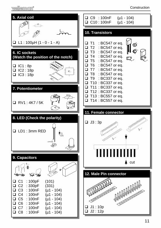
L1 : 100µH (1 - 0 - 1 - A)
5. Axial coil L2
IC1 : 8p IC2 : 18p IC3 : 18p
6. IC sockets (Watch the position of the notch)
IC...
1
L...
RV1 : 4K7 / 5K
7. Potentiometer RV1
LD1 : 3mm RED
8. LED (Check the polarity)
LD1
CATHODE
C1 : 100pF (101) C2 : 330pF (331) C3 : 100nF (µ1 - 104) C4 : 100nF (µ1 - 104) C5 : 100nF (µ1 - 104) C6 : 100nF (µ1 - 104) C7 : 100nF (µ1 - 104) C8 : 100nF (µ1 - 104)
c...
9. Capacitors
C9 : 100nF (µ1 - 104) C10 : 100nF (µ1 - 104)
T1 : BC547 or eq. T2 : BC547 or eq. T3 : BC547 or eq. T4 : BC547 or eq. T5 : BC547 or eq. T6 : BC547 or eq. T7 : BC547 or eq. T8 : BC547 or eq. T9 : BC337 or eq. T10 : BC337 or eq. T11 : BC337 or eq. T12 : BC337 or eq. T13 : BC557 or eq. T14 : BC557 or eq.
10. Transistors
J3 : 3p
11. Female connector
J ...
J ...
cut
J1 : 10p J2 : 12p
12. Male Pin connector
Construction
12
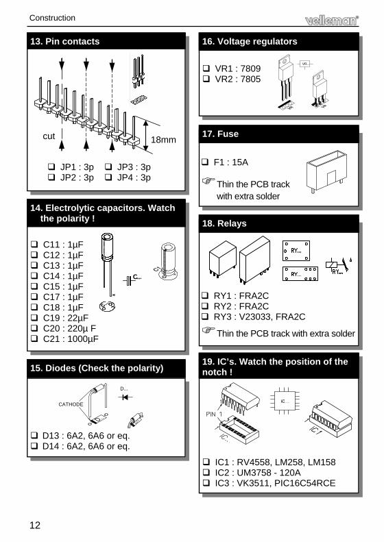
13. Pin contacts
18mm cut
C11 : 1µF C12 : 1µF C13 : 1µF C14 : 1µF C15 : 1µF C17 : 1µF C18 : 1µF C19 : 22µF C20 : 220µ F C21 : 1000µF
14. Electrolytic capacitors. Watch the polarity !
C...
D13 : 6A2, 6A6 or eq. D14 : 6A2, 6A6 or eq.
15. Diodes (Check the polarity)
CATHODE
D...
JP1 : 3p JP2 : 3p
JP3 : 3p JP4 : 3p
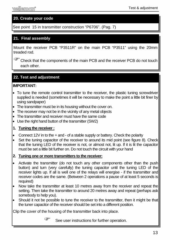
VR1 : 7809 VR2 : 7805
16. Voltage regulators
VR...
F1 : 15A
Thin the PCB track with extra solder
17. Fuse
RY1 : FRA2C RY2 : FRA2C RY3 : V23033, FRA2C
Thin the PCB track with extra solder
18. Relays
IC1 : RV4558, LM258, LM158 IC2 : UM3758 - 120A IC3 : VK3511, PIC16C54RCE
19. IC’s. Watch the position of the notch !
Construction
13
Mount the receiver PCB “P3511R” on the main PCB “P3511” using the 20mm treaded rod.
Check that the components of the main PCB and the receiver PCB do not touch each other.
21. Final assembly
See point 15 in transmitter construction “P6706”. (Pag. 7)
20. Create your code
IMPORTANT:
• To tune the remote control transmitter to the receiver, the plastic tuning screwdriver supplied is needed (sometimes it will be necessary to make the point a little bit finer by using sandpaper)
• The transmitter must be in its housing without the cover on. • The receiver may not be in the vicinity of any metal objects • The transmitter and receiver must have the same code • Use the right hand button of the transmitter (SW2)
1. Tuning the receiver :
• Connect 12V in to the + and - of a stable supply or battery. Check the polarity • Set the tuning capacitor of the receiver to around its mid point (see figure 8). Check
that the tuning LED of the receiver is not, or almost not, lit up. If it is lit the capacitor must be set a little bit further on. Do not touch the circuit with your hand
2. Tuning one or more transmitters to the receiver:
• Activate the transmitter (do not touch any other components other than the push button) and turn (very carefully) the tuning capacitor until the tuning LED of the receiver lights up. If all is well one of the relays will energise - if the transmitter and receiver codes are the same. (Between 2 operations a pause of at least 5 seconds is required)
• Now take the transmitter at least 10 metres away from the receiver and repeat the setting. Then take the transmitter to around 20 metres away and repeat (perhaps ask somebody to help you).
• Should it not be possible to tune the receiver to the transmitter, then it might be that the tuner capacitor of the receiver should be set into a different position.
Clip the cover of the housing of the transmitter back into place.
See user instructions for further operation.
22. Test and adjustment
Test & adjustment
14
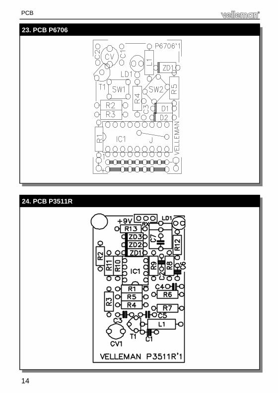
23. PCB P6706
PCB
24. PCB P3511R
15
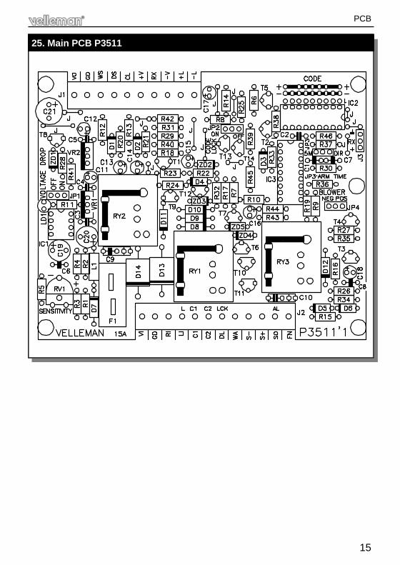
25. Main PCB P3511
PCB
16
26. Diagram Remote Transmitter
Diagram
D1
4
BA
TT
ER
Y12
V-+
A11
A12
SW
1S
W2
D2
UM
3758
-120
A
NC
A10
10
A9
A8
98
A6
A7
76
A5
5
17 14 1211
VS
S
TX
13
IC1
OS
C
A4
A3
3
A2A1
21
MO
DE
VD
D
16
1815
RX
NC
R1
L2
C1
T1
R3
R2
C3
C2
R4
CV
LD1
R5
ZD
1
L1

17
27. Diagram Remote Receiver
R9 A
1L2
R5
R6
L1C1
R7
T1
C5
A1,
A2
= IC
1
C4
R4
CV
1
R3
C3
R1
R8
C6
C7
R2
A2
GN
D
Rx
OU
T
ZD
2Z
D1
R13
ZD
3LD
1
+9V
R11
31
2
C2
R10
5 648
7
R12
Diagram
18
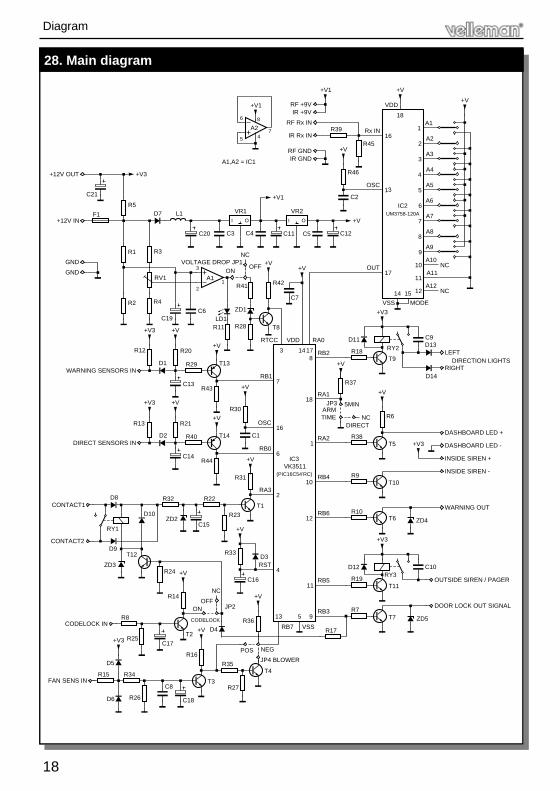
28. Main diagram
Diagram
WARNING OUT
DIRECTION LIGHTS
VDD C9D11RY2
RA0RTCC
+V+V3R28
R22
D4
T3
CODELOCK
R29
R40
R24 +V
CODELOCK IN
FAN SENS INC8
R26D6 C18
R8
R25
R34
D5
R15
+V3 C17
T2+V
R16
R14
CONTACT1
CONTACT2
WARNING SENSORS IN
DIRECT SENSORS IN
C14
D10
T12
RY1
D9
ZD3
D8
C15ZD2
R32
D2
R13
+V3
R21
+V
D1
R12 R20
C13
C10
T11
RY3C16
R7
R19
R27
T4
13R36
POS
R35
NEG
+V
R17VSSRB7
5 9
11
RB3
RB5
ZD5T7
OUTSIDE SIREN / PAGER
DOOR LOCK OUT SIGNAL
R37
R38
R10
R9
D12
R18
+V IC3
2
4
(PIC16C54’RC)
R23
R33
+V
D3RST
R31
T1
RA3
12
VK3511
10
RB6
RB4
7
16
6
R30
C1
RB0
OSC
+V
RB1
1
18
RA2
RA1
1738
14
+V
RB2
INSIDE SIREN +
+V3
ZD4T6
+V3
T10
INSIDE SIREN -
+V
T5
R6
T9
DASHBOARD LED -
DASHBOARD LED +
LEFT
RIGHTD14
D13
A1
+12V IN
GND
GND
+12V OUT
D7 L1F1
R2
R1
RV1
C19
R4
C6
2
R3
3
C20
+V3
+V
+V+V1
R46
+V
C2
R39
+V
C12
I O
VR2
I O
VR1
C11
R42
T8
R41
ZD1
1
VOLTAGE DROP JP1
C3
+V
C4
+V
C7
C5
+V1
A1,A2 = IC1
A2
5
6
74
+V1
8
IR GND
IR +9V
RF GND
RF +9V
RF Rx IN
IR Rx IN
7
MODE
+V3
14
VSS
15
OUT17
11A12
12 NC
A9
A10
A1110
9
NC
A88
UM3758-120A
R45
OSC13
IC2
Rx IN16
18
VDD
3
5
A7
A66
A5
A44
1
A3
A22
A1
C21
R5
R11LD1
T13
T14
+V
+V
R43
R44
JP3 5MIN
NCDIRECT
ARMTIME
NC
OFFON
JP4 BLOWER
NC
OFFON JP2

VELLEMAN KIT NV Legen Heirweg 33
9890 Gavere Belgium Europe
Info ?: http://www.velleman.be
Modifications and typographical errors reserved © Velleman Kit nv H3511IP - 2003 - ED2 (rev 3)
5 4 1 0 3 2 9 2 9 1 5 1 8