Embed Size (px)
Citation preview

K3330 – CFI Valves PLC/SCADA/RIO FDS
P a g e 1 | 47
2123421-1-000-E-SP-0003 FUNCTIONAL DESIGN SPECIFICATION
REMOTELY CONTROLLED ACTUATED VALVES SYSTEM – REV 0B
Rev 0.B

K3330 – CFI Valves PLC/SCADA/RIO FDS
P a g e 2 | 47
Table of Contents
1 DOCUMENT PREVIEW ........................................................................................................ 5
Table of Figures ............................................................................................................ 5
List of References ......................................................................................................... 6
Revision Control ........................................................................................................... 6
Definitions and Abbreviations ..................................................................................... 7
2 PROCESS OVERVIEW ......................................................................................................... 8
Background ................................................................................................................... 8
Foam Distribution ......................................................................................................... 8
Implementation ......................................................................................................... 8
Operation.................................................................................................................. 8
Leak Detection ............................................................................................................ 10
Background ............................................................................................................ 10
Implementation ....................................................................................................... 10
Operation................................................................................................................ 11
3 SCOPE OF WORK .............................................................................................................. 12
Control and Automation ............................................................................................. 12
Remote I/O Stations .................................................................................................... 12
4 SPECIFICATION, STANDARDS AND REGULATIONS ..................................................... 13
5 GENERAL PROJECT SPECIFICATION AND DETAILS ................................................... 13
Uniformity of Equipment ............................................................................................ 13
Standard of Work, Equipment and Materials ............................................................ 13
Training ........................................................................................................................ 14
Commissioning and Handover .................................................................................. 14
Guarantee and Warrantee .......................................................................................... 15
Operating and Maintenance Manuals ........................................................................ 15
Testing, Commissioning and Quality Control Procedures ..................................... 16
Factory Acceptance Tests (FAT) ............................................................................ 16
Loop Tests, Quality Control Procedure (QCP) ....................................................... 16
Cold Commissioning .............................................................................................. 16
Site Acceptance Tests (SAT) ................................................................................. 16
Hand Over .............................................................................................................. 16
6 CONTROL SYSTEM REQUIREMENTS ............................................................................. 17
Current PLC / SCADA Layout .................................................................................... 17
New PLC / SCADA Layout .......................................................................................... 17
PLC ............................................................................................................................... 17
PLC Hardware requirements .................................................................................. 17
PLC I/O Requirements ........................................................................................... 18
K3330 – CFI Valves PLC/SCADA/RIO FDS
P a g e 3 | 47
Loop Check Sheets ................................................................................................ 18
PLC Software ......................................................................................................... 18
Wonderware ArchestrA SCADA ................................................................................ 18
SCADA Hardware requirements ............................................................................. 19
Existing SCADA CFI application ............................................................................. 19
Mimics to be developed .......................................................................................... 19
Wonderware Historian ............................................................................................ 19
Wonderware Servers .............................................................................................. 19
Wonderware New Control/View Stations ................................................................ 20
Documentation ............................................................................................................ 20
Responsibilities .......................................................................................................... 21
Electrical ................................................................................................................. 21
Punchlist ................................................................................................................. 21
Operations Involvement ......................................................................................... 21
Inputs / Outputs of PLC .............................................................................................. 21
Analog Inputs (AI) ................................................................................................... 21
Discrete Valves (XV) .............................................................................................. 22
Digital Inputs (DI) .................................................................................................... 22
Digital Outputs (DO) ............................................................................................... 23
Alarms and Interlocks ................................................................................................ 23
Recording and Trending Requirements .................................................................... 23
Process Control Description .................................................................................. 24
Foam Distribution ................................................................................................ 24
Leak Detection .................................................................................................... 24
7 REMOTE I/O STATIONS .................................................................................................... 27
Overall layout .............................................................................................................. 27
Main PLC Panel ........................................................................................................... 28
Remote I/O Station Panel Requirements .................................................................. 28
Panel Internal Wiring and Labelling .......................................................................... 29
Field Instrumentation ................................................................................................. 29
Power Supply to RIO Stations ................................................................................... 30
Power cabling layout .............................................................................................. 30
Power cabling detail ............................................................................................... 31
Cable requirements ................................................................................................ 32
Communication network to RIO Stations ................................................................. 33
Fibre Optic cabling layout ....................................................................................... 33
Fibre optic cabling detail ......................................................................................... 34
Fibre Optic Installation ............................................................................................ 35
Fibre Optic Converters ........................................................................................... 35
Fibre Splice Enclosure ........................................................................................... 35
Ethernet Cabling ..................................................................................................... 35
Redundant Equipment ............................................................................................ 35
General ........................................................................................................................ 36

K3330 – CFI Valves PLC/SCADA/RIO FDS
P a g e 4 | 47
Cable Routes .......................................................................................................... 36
Trenching ............................................................................................................... 36
Cable Measurements and Final Positions .............................................................. 36
PLC and Remote I/O Station cabling to field instruments ....................................... 36
Power Cabling ........................................................................................................ 36
Instrument Cabling ................................................................................................. 36
PLC ........................................................................................................................ 37
RIO 1 ...................................................................................................................... 38
RIO 2 ...................................................................................................................... 39
RIO 3 ...................................................................................................................... 40
RIO 4 ...................................................................................................................... 41
RIO 5 ...................................................................................................................... 42
RIO 6 ...................................................................................................................... 43
RIO 7 ................................................................................................................... 44
Foam Station 1 .................................................................................................... 45
Foam Station 2 .................................................................................................... 46
Bubble screen PLC ............................................................................................. 47

K3330 – CFI Valves PLC/SCADA/RIO FDS
P a g e 5 | 47
1 DOCUMENT PREVIEW
Table of Figures
Figure 1 Current InTouch SCADA CFI Ring Main Overview mimic example pg26 Figure 2 Layout of PLC, RIO stations, mini sub-stations and existing foam stations pg27 Figure 3 Cable routes from sub-station supply to RIO panels pg30 Figure 4 Cabling layout of Fibre-Optic route tie-in to existing fibre network pg33 Figure 5 E&I cabling layout from PLC panel to field devices pg37 Figure 6 E&I cabling layout from RIO 1 station to field devices pg38 Figure 7 E&I cabling layout from RIO 2 station to field devices pg39 Figure 8 E&I cabling layout from RIO 3 station to field devices pg40 Figure 9 E&I cabling layout from RIO 4 station to field devices pg41 Figure 10 E&I cabling layout from RIO 5 station to field devices pg42 Figure 11 E&I cabling layout from RIO 6 station to field devices pg43 Figure 12 E&I cabling layout from RIO 7 station to field devices pg44 Figure 13 E&I cabling layout from FS1 RIO station to field devices pg45 Figure 14 E&I cabling layout from FS2 RIO station to field devices pg46 Figure 15 Wireless network from Pressure Tx 5 to Bubblescreen pg47

K3330 – CFI Valves PLC/SCADA/RIO FDS
P a g e 6 | 47
List of References
Name Date Revision Author
Transnet Automation Control Standards 11-05-2015 0.95 Juan Le Roux
CFI Island View Upgrade Actuated Valve and Pressure Transmitter Schematic 2123421-1-000-M-SD-0004-01-0C-TD-A0
23-04-2015 OC Tim Dunnell
2123421-1-000-E-SP-0001 PSX Electrical 31-03-2015 0.0 K&T
CFI Valve Automation PLC-SCADA-RIO Schedule of Quantities
15-05-2015 0.0 Warren Hofland
2123421-1-000-E-GA-0003-01 PLC and RIO panel layout drawing
20-05-2015 0.0 Peter Gilliver
CFI Valve and pressure cable schedule 20-05-2015 0.0 Warren Hofland
2123421-1-000-E-IO-0001 Valve matrix spreadsheet
29-03-2015 2.0 K&T
2123421-1-000-E-SP-0003 TCP Rotork Actuator IQ3 Remote Connection Diagram
20-06-2015 0.0 Warren Hofland
Revision Control
Revision Date Name Comment
0.0 11.05.2015 Warren Hofland Draft for K&T comment
0.1 29.05.2015 Warren Hofland For TCP review
0.B 22.06.2015 Warren Hofland For K&T changes requested

K3330 – CFI Valves PLC/SCADA/RIO FDS
P a g e 7 | 47
Definitions and Abbreviations
N/A Not Applicable CFI Cutler Fire Installation PLC Programmable Logic Controller SCADA Supervisory Control and Data Acquisition I/O Inputs / Outputs (of PLC) RIO Remote Input/Outputs (of PLC) FCP Field Control Panel FDS Functional Design Specification DDS Detailed Design Specification P&ID Piping and Instrumentation Diagram SOP Standard Operation Procedure LHS Left hand side RHS Right hand side DFB Derived Function Block DDT Derived Data Type FS Foam Station TX Transmitter

K3330 – CFI Valves PLC/SCADA/RIO FDS
P a g e 8 | 47
2 PROCESS OVERVIEW
Background
The operation of the CFI fire water system at the Port of Durban is normally a pressurised sea water system fed to the various consumers by means of a network of piping. There are several paths to each site with isolation valves, to allow for isolation of sections of the pipe for maintenance or isolation of ruptured sections. This flexibility hinders the rapid flow of foam premix solution if a decision has been taken to introduce foam from one of the central foam injection sites at Pump Station 2 and proposed for Pump Station 1. If all the isolation valves in the fire water ring main are open, there will be more than one route to the consumer from the foam injection point, which delays the time for foam premix at the required concentration. In addition to the requirement to line up the network to permit rapid distribution of foam premix, a system is required to ensure that leaks or unauthorised use of the fire network is detected and located. The current method of operation is that the network is segmented manually to determine the location of the water use. This process is labour intensive and time consuming. By actuating strategic valves and installation of pressure transmitters, the location of the leak can be located in a zone of the CFI system much more rapidly. Once the zone has been identified, the exact location can be determine manually.
Foam Distribution
Implementation
Once the decision has been made to introduce foam concentrate into the ring main, the appropriate isolation valves will be operated to ensure that the shortest practical path from the injection point is lined up, with no parallel paths.
Operation
2.2.2.1 Remote Monitoring & Control
The actuated valves on the ring main will be monitored and controlled from the Fire Control office near to berth 4 as well as from the TNPA Operations Centre (the old JBS building). The authorised operators will be able to monitor the status of the valves, including:
Valve open position
Valve closed position
Valve local or remote
Actuator “healthy”, which includes power on the actuator The information will be shown on the Wonderware ArchestrA SCADA system.

K3330 – CFI Valves PLC/SCADA/RIO FDS
P a g e 9 | 47
There will be 20 remotely actuated valves on the fire ring main. 17 of these actuated valves are isolation valves. 3 of the actuated valves are scour valves to purge the system, which will aid in quicker foam distribution to the required take off point. The foam pumps will be locally operated as well as remotely operated from either the Fire Control Office or the TNPA Operations Centre. There will be a local start / stop station at the pump with a local / remote switch. At each of the two control rooms the status of the two Alcoseal foam pumps in Foam Station 1 and the two foam pumps in Foam Station 2 will be displayed. If the foam pump is in “remote”, the foam pump can be started and stopped from the control room. Each foam pump will have two foam concentrate actuated valves: one to introduce foam concentrate into the system and one which will increase the foam concentration from 3% to 6%. Each of these 8 actuated valves will indicate the valve status as above and will be able to be remotely operated if the valve is in remote mode.
2.2.2.2 Initial Firefighting
During normal operation, the isolation valves would all be open and the jockey pumps would pressurise the fire ring main. If a fire is detected at one of the sites, the fire alarm will be raised and the firefighters will operate the fixed or portable equipment on site. The pressure drop will cause the main sea water pumps to operate, either at pump station 1 or pump station 2. The “foam on wheels” will be brought in to introduce foam local to the incident. This is the present arrangement and it is not proposed to make any significant changes to the operation up to this point.
2.2.2.3 Introduction of Foam
If the fire cannot be contained with this approach, the decision will be taken to introduce foam into the ring main from either foam station 2 or else from the foam station 1, once it has been upgraded to allow the foam to be injected into the system. The sea water pumps associated with the foam station need to be the only source of water in the system. If the sea water pumps in pump station 1 are operating, but it has been decided to inject foam using foam station 2, then the sea water pumps in pump station 2 need to be started and the sea water pumps in pump station 1 need to be stopped. If they are not stopped, the foam concentrate will not achieve the desired concentration as the additional pumps will dilute the foam premix solution. Once the source of foam injection has been decided and the location of the fire has been confirmed, the appropriate actuated ring main isolation valves need to be closed to ensure a single path for the foam premix to follow. The foam concentrate pump can be started and the foam concentrate valve opened. If 6% foam is required, the 6% foam valve can be opened.

K3330 – CFI Valves PLC/SCADA/RIO FDS
P a g e 10 | 47
If only the minimum number of valves are closed, the rest of the sea water ring main will remain pressurised and available for use on any other site connected to the sea water network. If more valves are closed that the minimum number, note that sections of the network will be isolated from the pump stations and could potentially be at risk.
2.2.2.4 Exceptional Operation
If a section of the sea water pipework has been isolated either for preventative maintenance or else to isolate a leak, the firefighters need to determine an alternative route from the water and foam pump stations to the take off. The appropriate actuated valves need to be closed to ensure the shortest route with no parallel paths. There are 89 isolation valves (of which 17 are proposed to be actuated) and 39 consumer take off points supplied from the two pump / foam stations. The permutations to consider the most appropriate path and which actuated valve needs to be closed considering all the other valves is a complex process, but can fairly simply be undertaken once the isolated section is known.
Leak Detection
Background
The CFI system is pressurised with jockey pumps operating to maintain pressure. If a small leak occurs, the jockey pumps will operate more frequently. If there is a sizable leak, the jockey pump will be unable to maintain the pressure and the main fire pump will be started. The leak could be due to any of the following:
A leak in the CFI ring main
A leak in the consumers’ fire network
A hydrant open
A deliberate unauthorised use of fire water. In order to identify the location of the leak, the network will be segmented by the actuated valves and then monitoring the pressure in each segment of the CFI system. The segment that loses pressure the quickest will be the segment that contains the leak. At that stage, personnel can be sent to the segment to further segment it by operating the manual isolation valves, allowing the leak to be detected by a process of elimination.
Implementation
There will be 17 remote actuated isolation valves along the fire ring main network and a pressure transmitter will be installed in an inspection “T” in each zone to permit the monitoring the pressure.

K3330 – CFI Valves PLC/SCADA/RIO FDS
P a g e 11 | 47
Operation
It is proposed that the system be tested on a regular basis to determine if a leak exists. All 17 isolation valves will be closed, segmenting the network into 10 zones. The jockey pumps need to be switched off to ensure that the zone that the jockey pumps feed is not re-pressurised. The pressure in each zone can be monitored and a leak detected if the pressure reduces at a faster rate than expected. Once the system is in operation for some time, the normal rate of change of pressure will be determined and used as a yardstick. If a zone is suspected of a leak, personnel will need to be sent to operate the rest of the isolation valves in the segment in order to further identify the location of the leak.

K3330 – CFI Valves PLC/SCADA/RIO FDS
P a g e 12 | 47
3 SCOPE OF WORK The system will control and monitor 28 actuated valves and 11 pressure transmitters via 1 PLC station with 7 remote I/O stations, including 3 new SCADA stations. This contract outlines the necessary equipment in order to provide a fully functional control system.
Control and Automation
SCADA Control stations
PLC Engineering
PLC Software upgrade
SCADA Engineering of new valves
SCADA Engineering of existing CFI InTouch to ArchestrA
FAT Tests
Commissioning and Handover
Documentation
Remote I/O Stations
Supply and install remote I/O panels
Supply and install Fibre optic network to each RIO station including fibre converters.
Supply and install power cabling to each RIO station
Supply and populate remote I/O and all required hardware within RIO station
Cable trenching, cable trays where required.
Supply Documentation

K3330 – CFI Valves PLC/SCADA/RIO FDS
P a g e 13 | 47
4 SPECIFICATION, STANDARDS AND REGULATIONS The entire installation shall be carried out in accordance with the latest revision and
amendments of the following:
• The Occupation and Safety Amendment Act (Act No 181 0f 1993) including all regulations,
compulsory and safety standards promulgated in terms of the Act.
• The Wiring Code SANS 10142-1 as issued by the South African Bureau of Standards.
• The Municipal By-Laws and any special requirements of the Supply Authorities of the area
and district concerned.
• The local Fire Office Regulations.
5 GENERAL PROJECT SPECIFICATION AND DETAILS
Uniformity of Equipment
Where the Specification calls for specific makes and types of equipment, the tender prices
shall be based on such equipment. Tenderers may offer other equipment only as
alternatives to their main offers, clearly indicating savings and benefits that would accrue to
the Client through acceptance of such alternative offers. The Contractor must however price
on the equipment specified in the bill and only then offer the alternative. Contractors who do
not price the bill as specified, in addition to their alternatives will be treated as non-compliant.
All equipment of a particular type shall be of identical manufacture and model throughout
the installation unless the specification requires otherwise, or is specifically authorized to
the contrary by the Principal Agent.
Standard of Work, Equipment and Materials
The material and equipment specified and any of the accessories necessary for the correct
execution of work, shall be supplied, delivered to site and installed in accordance with the
highest engineering standards. Installation work shall be carried out by qualified staff under
proper supervision by experienced and competent supervisory personnel.
Unless otherwise specified, all proprietary equipment shall be used and placed in strict
accordance with the relevant manufacturer's instructions. SANS and/or NCRS certificates
or authorisation permit numbers must be provided for all of the new equipment supplied.
Unless otherwise specified, all materials used in the contract shall be new. Any previously
used materials, or damaged materials, will be rejected by the Principal Agent and shall be
replaced, all costs being for the Contractor’s account. When required by the Principal Agent,
the Contractor shall furnish all information relating to the equipment and materials to be
used in the Works and shall give the Principal Agent such other particulars as may be
requested. When requested, the Contractor shall provide samples, information and

K3330 – CFI Valves PLC/SCADA/RIO FDS
P a g e 14 | 47
manufacturer's test certificates for the equipment to be incorporated in the Works. The
installation shall be such that future maintenance is made as easy as possible. In all cases,
sample installations will first be checked and approved before the full installation proceeds.
Training
On completion of the installation, the contractor will be required to provide training in the use
of the equipment. This training shall be formal and, as a minimum, take the following format:
• Set dates and list of attendees with the operations management.
• Submit to the Principal Agent, at least 2 weeks prior to the training, a training program and
all the required training documentation and presentations for approval.
• Training to take place as both lectures and demonstrations.
• On completion, each delegate to be given a handbook that covers the training undertaken.
• Each delegate to then sign to confirm that training has taken place and that they have been
issued with the handbook. This document is then to be affirmed and signed off by the
delegate’s superior.
• It shall be assumed that this training will take at least 2 days to complete.
• Each delegate that attends the training and passes the exam shall receive a Certificate of
Training.
The Contractor shall allow training for a minimum of 5 operators, 5 technical staff and 5
managers.
Commissioning and Handover
The installation shall be comprehensibly tested and commissioned as individual and
integrated systems as may be required by the configuration, after the works are substantially
complete.
The Contractor shall provide adequate and competent personnel for testing and
commissioning of every particular installation for the full duration of the commissioning
process.
The commissioning shall include interaction between other services and contractors where
interdependence of installations are encountered.
The commissioning process shall, after all testing has been completed be the final proving
ground of the systems and during this procedure the installations shall be subjected to all
possible inputs and actions which may be encountered under operational conditions. The
Contractor shall prove the full operation, working and compliance of the installation in
accordance with the specifications.

K3330 – CFI Valves PLC/SCADA/RIO FDS
P a g e 15 | 47
A detailed programme of the planned commissioning procedures shall be submitted to the
Principal Agent at least 10 days before commissioning commences to enable the Principal
Agent to witness the commissioning.
The commissioning programme shall include:
• A schedule of equipment to be commissioned, the proposed tests to be conducted and the
testing methods and the range of acceptable results,
• Commissioning check sheets,
• Commissioning programme dates and duration,
The Contractor shall supply all relevant test equipment, monitoring devices, network
analysers, protocol testers/analysers etc. required to test and commission the complete
works.
An accurate record of all commissioning and testing is to be taken and included in the
handover documentation as a permanent record.
Guarantee and Warrantee
The Project Specification defines the Guarantee and Warrantee conditions.
In addition, certain components are specified with extended warranty. These warranties are
to be ceded to the client on completion of the standard contract guarantee and warranty.
Operating and Maintenance Manuals
On completion of the contract, the contractor is to hand over to the Principal Agent, 3 sets
of Operating and Maintenance Manuals.
The minimum requirements for these manuals are as follows:
• Bound in plastic coated lever arch file, clearly labelled and having an index and plastic
section dividers.
• Contain only technical information and no marketing literature.
• Contain details of local and international contact details for support:
• Contain technical specifications, schematics and set-up information.
• Contain full operational details.
• List of software that forms part of the installation.
• A full schedule of planned maintenance required to maintain and clean the full installation.
K3330 – CFI Valves PLC/SCADA/RIO FDS
P a g e 16 | 47
• Copies of all equipment guarantees.
• Any additional information considered necessary to maintain and operate the installation.
• A full set of “As Built’ drawings and any other drawings pertinent to the installation.
• The commissioning check sheets.
• A schedule of all operation set points and parameters.
The manuals are to be available on a compact disc in electronic format as well.
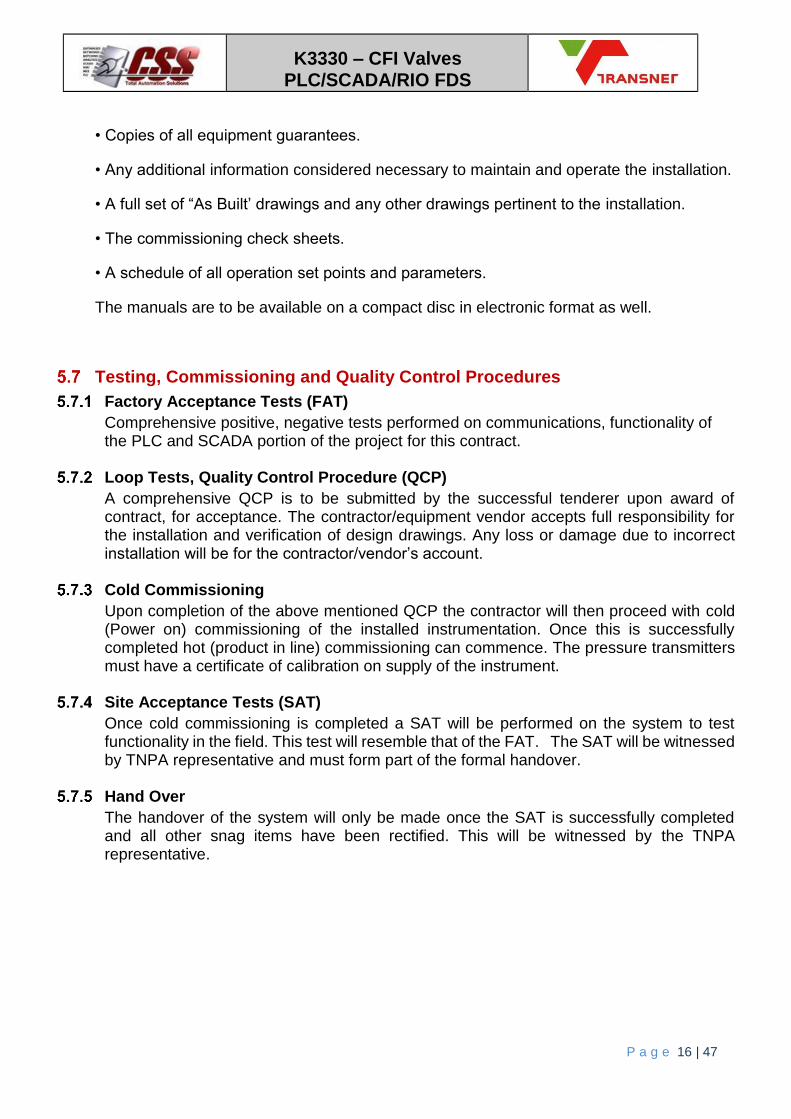
Testing, Commissioning and Quality Control Procedures
Factory Acceptance Tests (FAT)
Comprehensive positive, negative tests performed on communications, functionality of the PLC and SCADA portion of the project for this contract.
Loop Tests, Quality Control Procedure (QCP)
A comprehensive QCP is to be submitted by the successful tenderer upon award of contract, for acceptance. The contractor/equipment vendor accepts full responsibility for the installation and verification of design drawings. Any loss or damage due to incorrect installation will be for the contractor/vendor’s account.
Cold Commissioning
Upon completion of the above mentioned QCP the contractor will then proceed with cold (Power on) commissioning of the installed instrumentation. Once this is successfully completed hot (product in line) commissioning can commence. The pressure transmitters must have a certificate of calibration on supply of the instrument.
Site Acceptance Tests (SAT)
Once cold commissioning is completed a SAT will be performed on the system to test functionality in the field. This test will resemble that of the FAT. The SAT will be witnessed by TNPA representative and must form part of the formal handover.
Hand Over
The handover of the system will only be made once the SAT is successfully completed and all other snag items have been rectified. This will be witnessed by the TNPA representative.

K3330 – CFI Valves PLC/SCADA/RIO FDS
P a g e 17 | 47
6 CONTROL SYSTEM REQUIREMENTS
Current PLC / SCADA Layout
Currently there is a hot standby main PLC (Schneider Electric Premium PLC) at the CFI
Control room. All remote I/O (CFI Switchgear substation / Pump Stations 1 and 2, Foam
Stations 1 and 2) communicate via an Ethernet fibre optic network to the main PLC. There
are two InTouch SCADA control stations, one at the CFI control room and the other at the
Fire Office (by Berth 4). These are used by the fire officers to monitor and control the plant.
New PLC / SCADA Layout
The contractor will be responsible for sourcing, installing and commissioning of new RIO
and main PLC panels, wiring of all actuated valves and pressure transmitters to the remote
I/O, installing fibre-optic cable between all RIO stations back to the existing fibre optic
network, integration of the new RIO into the existing ethernet network, re-commissioning,
checking network stability and integrity.
A PLC control cabinet will be installed in Fynlands Generator Substation. This will be the
Schneider Electric M580 PLC to control the valve automation and pressure monitoring
system. It will connect via a fibre-optic network to new remote I/O drops as well as to the
existing PLC network in order to communicate to the foam stations remote I/O. Note that all
writing of command data to existing remote I/O must be done via the existing PLC, using it
as a gateway to the remote I/O to prevent multiple writes to the same end remote
module/device.
The monitoring and control of the actuated valves and pressure transmitters on the CFI ring
main will be viewed on three new PC stations, which will be added into the existing Transnet
ArchestrA System Platform SCADA. The three new SCADA PC’s will be at the Fire Control
Office near to berth 4, the CFI control room and the TNPA Operations Centre (the old JBS
building).
All networks between the main buildings, sub-stations and remote I/O as well as the foam
stations are fibre-optic network media.
PLC and SCADA I/O and objects to be built in accordance with the “Transnet Automation
Control Standards’ document.
PLC
PLC Hardware requirements
The contractor will be responsible for supplying all PLC related equipment. (M580 PLC

K3330 – CFI Valves PLC/SCADA/RIO FDS
P a g e 18 | 47
and M340 remote I/O stations) All required cables and racks will be sourced and installed
according to Transnet standards by the contractor. Project time lines are to be supplied
by the contractor to Transnet so as to allow for a smooth transition to the new plant
controls. Quotations are encouraged to show specific pricing in order to eliminate any
misunderstandings at an early stage and also to help simplify the delivery.
Refer to document ‘CFI Valve Automation PLC-SCADA Schedule of Quantities’
PLC I/O Requirements
Momentum X80 remote I/O on Modbus-Ethernet will be used for this project. At least 20%
spare capacity should be planned for by the contractor. The recommended I/O and
relevant network components to be sourced will be the responsibility of the contractor.
Power and distance requirements have to be taken into consideration by the contractor.
Reasonable spare I/O and RIO panel enclosure space will be encouraged for future use.
Loop Check Sheets
All I/O will be tested using loop check sheets testing from field to PLC, and thereafter
field to SCADA, which will require acceptance from the TNPA representative.
PLC Software
The latest version of Unity will be used for PLC software engineering. Only function block
logic (with appropriate DFB and DDT’s) as per current Transnet standards are to be used
for this project. A copy of the latest CFI_PLC application can be obtained by the contractor
from Transnet. PLC backups must be done and provided to Transnet. The DDS will be
developed by the contractor and will be reviewed by Transnet and the contractor, and PLC
coding will only take place after approval by Transnet. Any proposed deviations to these
requirements need to be discussed and cleared by Transnet before implementation.
Wonderware ArchestrA SCADA
All SCADA tags will be configured by the contractor in ArchestrA as per TNPA standard.
Existing ArchestrA control module templates will be used to derive new control modules. All
alarming, plant modelling, historisation and security are to be done by the contractor via
ArchestrA. All engineering will be done via the Galaxy Repository server (10.0.4.6). Note:
this is a live system and new program edits will be imported on the run, so great care needs
to be taken to import latest development without affecting the current plant state whatsoever.

K3330 – CFI Valves PLC/SCADA/RIO FDS
P a g e 19 | 47
SCADA Hardware requirements
PC station at each with following specifications:
Part/Model No Description Qty
J0F02EA HP Desktop EliteDesk 800 G1 SFF, Intel Core i5-4590 3.2-Ghz, 4GB, DDR3-1600 DIMM 500GB 7200rpm HDD, SuperMulti DVD,USB K+M Win 8 Pro downgraded to Win 7 Pro 64 HP 3 Year NBD Warranty - Hardware
3
FH969AA HP Intel GbE CT Desktop 10/100/1000 NIC 3
C9E49AS HP 21.5" P221 LED Monitor 1920x1080, VGA, 1x DVI HP 3 Year Warranty - Hardware
3
Existing SCADA CFI application
The current CFI InTouch SCADA application will be updated and re-commissioned by the
contractor for this project. SCADA and PLC FAT developed by the contractor will be done
by the contractor, the subject matter expert and the TNPA representatives before going
live in the plant. A copy of the SCADA application can be obtained from the TNPA
Engineering department. All new SCADA and PLC tags will follow the TNPA standards.
Mimics to be developed
The contractor is encouraged to provide a HMI solution that is interactive indicating
process modes, interlocks, relevant alarming to be explained and handed over to fire
officers to ensure seamless change management.
All relevant analog and digital signals from valves and valve limits as well as zone pressures must be indicated on the CFI ring main overview mimic on the SCADA. When a valve is stroked, a “travelling” indication should be displayed once the open or close position indication is lost as the valve starts to move.
Wonderware Historian
The Wonderware SQL Server (10.0.4.8) will be used by the contractor as the historian and
a selected number of tags will be trended here from the ArchestrA tags.
Wonderware Servers
The AOS I/O server will operated on the selected local machine to channel I/O traffic from
the SCADA via Topserver OPC software application, whilst the redundancy will fail over to
the centralised AOS server (10.0.4.7) at Alan Dalton control room. Both these need to be
backed up and updated.
K3330 – CFI Valves PLC/SCADA/RIO FDS
P a g e 20 | 47
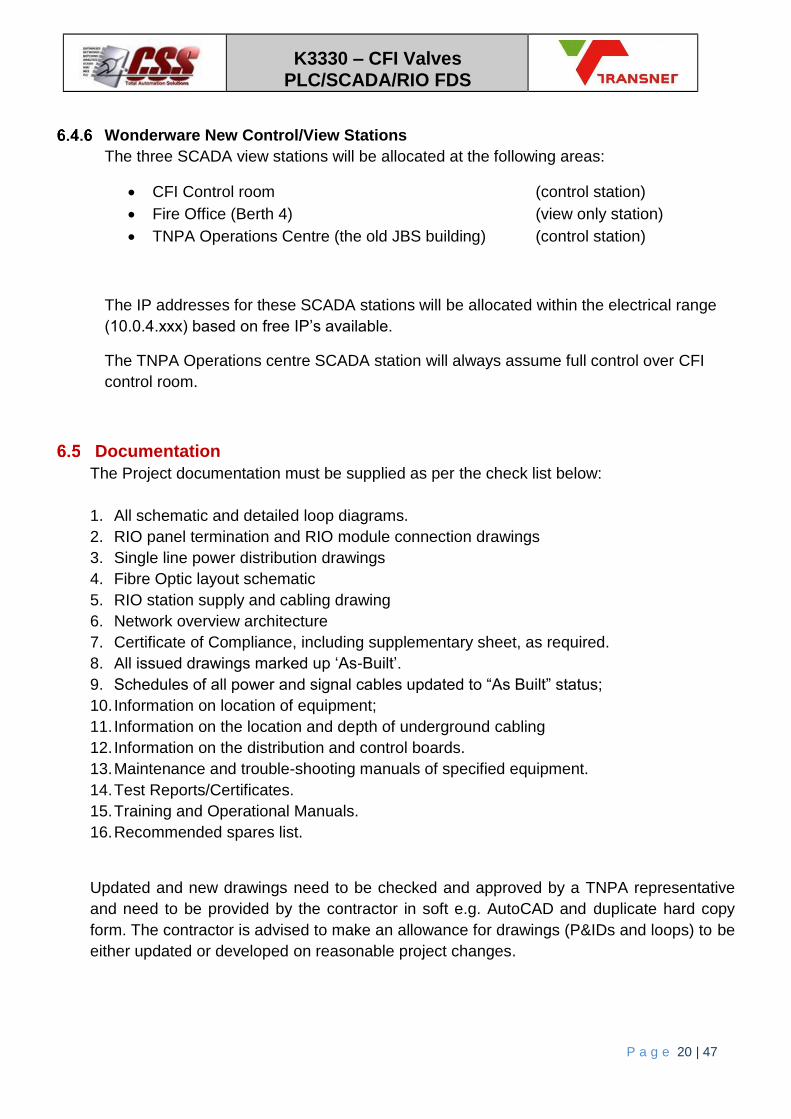
Wonderware New Control/View Stations
The three SCADA view stations will be allocated at the following areas:
CFI Control room (control station)
Fire Office (Berth 4) (view only station)
TNPA Operations Centre (the old JBS building) (control station)
The IP addresses for these SCADA stations will be allocated within the electrical range
(10.0.4.xxx) based on free IP’s available.
The TNPA Operations centre SCADA station will always assume full control over CFI
control room.
Documentation
The Project documentation must be supplied as per the check list below:
1. All schematic and detailed loop diagrams.
2. RIO panel termination and RIO module connection drawings
3. Single line power distribution drawings
4. Fibre Optic layout schematic
5. RIO station supply and cabling drawing
6. Network overview architecture
7. Certificate of Compliance, including supplementary sheet, as required.
8. All issued drawings marked up ‘As-Built’.
9. Schedules of all power and signal cables updated to “As Built” status;
10. Information on location of equipment;
11. Information on the location and depth of underground cabling
12. Information on the distribution and control boards.
13. Maintenance and trouble-shooting manuals of specified equipment.
14. Test Reports/Certificates.
15. Training and Operational Manuals.
16. Recommended spares list.
Updated and new drawings need to be checked and approved by a TNPA representative
and need to be provided by the contractor in soft e.g. AutoCAD and duplicate hard copy
form. The contractor is advised to make an allowance for drawings (P&IDs and loops) to be
either updated or developed on reasonable project changes.

K3330 – CFI Valves PLC/SCADA/RIO FDS
P a g e 21 | 47
Responsibilities
Electrical
The TNPA electrical department will be responsible for availing required power sources
which will then be wired and used by the contractor. Electrical drawings updates are the
responsibility of the contractor.
Punchlist
A punch list will be set up and forwarded to the contractor by TNPA to assure all project
requirements are met and completed. All punch list items must be closed before project
sign off.
Operations Involvement
The fire officers need to be updated on any changes to the plant so as to avert any
unnecessary harm and ensure system is ready for any emergency fire situations.
Inputs / Outputs of PLC
Refer to ‘Transnet Automation Control Standards’ document for tag naming convention and template object standards for both PLC (Derived function blocks and Derived data types) and SCADA.
Analog Inputs (AI)
TAG Description Comments
DCFI_RM_PT_001_MV
Foam Station 2 Ring Main Pressure
DCFI_RM_PT_002_MV Ceylon Rd South Ring Main Pressure
DCFI_RM_PT_003_MV
Berth 4 Ring Main Pressure
DCFI_RM_PT_004_MV Hokkaido Rd Ring Main Pressure
DCFI_RM_PT_005_MV
Venezuela Rd East Ring Main Pressure
DCFI_RM_PT_006_MV Venezuela Rd West Ring Main Pressure
DCFI_RM_PT_007_MV
Causeway Rd Ring Main Pressure
DCFI_RM_PT_008_MV Foam Station 1 Ring Main Pressure
DCFI_RM_PT_009_MV Trinidad Rd East Ring Main Pressure
DCFI_RM_PT_010_MV
Taiwan Rd Ring Main Pressure
DCFI_RM_PT_011_MV Trinidad Rd West Ring Main Pressure

K3330 – CFI Valves PLC/SCADA/RIO FDS
P a g e 22 | 47
Discrete Valves (XV)
TAG Description Comments
DCFI_RM_XV_105
Fire Water Ring Main Isolation Valve 105
DCFI_RM_XV_301
Fire Water Ring Main Isolation Valve 301
DCFI_RM_XV_405
Fire Water Ring Main Isolation Valve 405
DCFI_RM_XV_424 Fire Water Ring Main Isolation Valve 424
DCFI_RM_XV_504 Fire Water Ring Main Isolation Valve 504
DCFI_RM_XV_618 Fire Water Ring Main Isolation Valve 618
DCFI_RM_XV_706 Fire Water Ring Main Isolation Valve 706
DCFI_RM_XV_801 Fire Water Ring Main Isolation Valve 801
DCFI_RM_XV_1001 Fire Water Ring Main Isolation Valve 1001
DCFI_RM_XV_1005 Fire Water Ring Main Isolation Valve 1005
DCFI_RM_XV_624 Fire Water Scour Valve 624
DCFI_RM_XV_1010 Fire Water Scour Valve 1010
DCFI_RM_XV_401 Fire Water Ring Main Isolation Valve 401
DCFI_RM_XV_415 Fire Water Ring Main Isolation Valve 415
DCFI_RM_XV_501 Fire Water Ring Main Isolation Valve 501
DCFI_RM_XV_505 Fire Water Ring Main Isolation Valve 505
DCFI_RM_XV_419 Fire Water Ring Main Isolation Valve 419
DCFI_RM_XV_431 Fire Water Ring Main Isolation Valve 431
DCFI_RM_XV_1002 Fire Water Ring Main Isolation Valve 1002
DCFI_RM_XV_1110 Fire Water Scour Valve 1110
DCFI_FS1_XV_001 Foam Stn1 Pump 1 Foam Concentrate Valve 1
DCFI_FS1_XV_002 Foam Stn1 Pump 1 Foam Concentrate Valve 2
DCFI_FS1_XV_003 Foam Stn1 Pump 2 Foam Concentrate Valve 1
DCFI_FS1_XV_004 Foam Stn1 Pump 2 Foam Concentrate Valve 2
DCFI_FS2_XV_001 Foam Stn2 Pump 1 Foam Concentrate Valve 1
DCFI_FS2_XV_002 Foam Stn2 Pump 1 Foam Concentrate Valve 2
DCFI_FS2_XV_003 Foam Stn2 Pump 2 Foam Concentrate Valve 1
DCFI_FS2_XV_004 Foam Stn2 Pump 2 Foam Concentrate Valve 2
Digital Inputs (DI)
Digital inputs will be assigned for each one of the 28 actuated valves.
TAG Description Comments
DCFI_RM_XV_xxx_ZSO Valve open limit
DCFI_RM_XV_xxx_ZSC Valve closed limit
DCFI_RM_XV_xxx_REM Valve in remote operation
DCFI_RM_XV_xxx_HLT Valve is healthy - no fault conditions

K3330 – CFI Valves PLC/SCADA/RIO FDS
P a g e 23 | 47
Digital Outputs (DO)
Digital outputs will be assigned for each one of the 28 actuated valves.
TAG Description Comments
DCFI_RM_XV_xxx_OPN Valve open command
DCFI_RM_XV_xxx_CLS Valve close command
Alarms and Interlocks
Interlocks:
There are no interlocks stated on this project.
Alarms:
Low pressure
Low low pressure
High pressure
Valve not healthy
Valve travel time exceeded (valve acceptable stroke time determined during commissioning)
Events:
Valve in local control mode
Recording and Trending Requirements
All monitoring data shall be accessible to the operator from every view station console. Presentation of all monitored data shall be possible via trending graphs and from accessing the logged data which is recorded over time at pre-determined intervals. The following summarises the various signals and outputs for monitoring and recording.
All zone pressure readings
Any alarms
Valve status (open, close, local-remote, fault status)

K3330 – CFI Valves PLC/SCADA/RIO FDS
P a g e 24 | 47
Process Control Description
Foam Distribution
Once the decision has been made to introduce foam concentrate into the ring main, the appropriate isolation valves will be operated to ensure that the shortest practical path from the injection point is lined up, with no parallel paths. This control will be done manually by the authorised operator via the SCADA. The foam distribution route selection will not be done automatically by the PLC. The actuated valves on the ring main will be monitored and controlled from the Fire Control office near to berth 4 as well as from the TNPA Operations Centre (the old JBS building). The authorised operators will be able to monitor the status of the valves, including:
Valve open position
Valve closed position
Valve local or remote
Actuator “healthy”, which includes power on the actuator The information will be shown on the Wonderware ArchestrA SCADA system. There will be 20 remotely actuated valves on the fire ring main. 17 of these actuated valves are isolation valves. 3 of the actuated valves are scour valves to purge the system, which will aid in quicker foam distribution to the required take off point. The operator will reference the ‘Valve Matrix’ document, which shows which valves to close to allow the quickest distribution from the selected pump station to the selected consumer take-off point. The foam pumps will be locally operated as well as remotely operated from either the Fire Control Office or the TNPA Operations Centre. There will be a local start / stop station at the pump with a local / remote switch. At each of the two control rooms the status of the two Alcoseal foam pumps in Foam Station 1 and the two foam pumps in Foam Station 2 will be displayed. If the foam pump is in “remote”, the foam pump can be started and stopped from the control room. Each foam pump will have two foam concentrate actuated valves: one to introduce foam concentrate into the system and one which will increase the foam concentration from 3% to 6%. Each of these 8 actuated valves will indicate the valve status as above and will be able to be remotely operated if the valve is in remote mode.
Leak Detection
In order to identify the location of the leak, the network will be segmented by the actuated valves and then monitoring the pressure in each segment of the CFI system. The segment that loses pressure the quickest will be the segment that contains the leak. At that stage, personnel can be sent to the segment to further segment it by operating the manual isolation valves, allowing the leak to be detected by a process of elimination. There will be 17 remote actuated isolation valves along the fire ring main network and a pressure transmitter will be installed in an inspection “T” in each zone to permit the

K3330 – CFI Valves PLC/SCADA/RIO FDS
P a g e 25 | 47
monitoring of the pressure. It is proposed that the system be tested on a regular basis to determine if a leak exists.
6.10.2.1 Remote Control
The operator will be able to detect a change in normal operation when the jockey pumps are running too frequently to maintain the CFI ring main pressure. The authorised operator will select an ‘Activate Leak Detection’ push button on the SCADA which will then automatically close all 17 isolation valves, segmenting the network into 10 zones. The jockey pumps will be switched off to ensure that the zone that the jockey pumps feed is not re-pressurised. A CFI ring main overview mimic will display all 10 zones. The zones pressure line indications will change colour when the threshold pressure limits are reached. Warning status alarms will be displayed in the alarm viewer. Major alarm status will also be displayed in the alarm viewer as well as bringing a critical alarm popup on relevant operator workstation for operators to acknowledge and act upon. The alarms will indicate the zone which needs to be attended to. The alarm and event zone threshold limits are indicated in the table below:
Zone Pressure [bar] Status Zone colour
0 to 7.5 Major Alarm Red
7.5 to 8.5 Warning Orange
8.5 to 16 Healthy Green
16 to 18 Warning Orange
18+ Major Alarm Red
The pressure in each zone can be monitored and a leak detected if the pressure reduces at a faster rate than expected. Once the system is in operation for some time, the normal rate of change of pressure will be determined and used as a yardstick.

K3330 – CFI Valves PLC/SCADA/RIO FDS
P a g e 26 | 47
Figure 1: Current InTouch SCADA CFI Ring Main Overview mimic example
If a zone is suspected of a leak, personnel will need to be sent to operate the rest of the isolation valves in the segment in order to further identify the location of the leak.

K3330 – CFI Valves PLC/SCADA/RIO FDS
P a g e 27 | 47
7 REMOTE I/O STATIONS
Overall layout
Figure 2: Layout of PLC, RIO stations, mini sub-stations and existing foam stations

K3330 – CFI Valves PLC/SCADA/RIO FDS
P a g e 28 | 47
In figure 2, the PLC or remote I/O stations are represented by the green squares. Sub stations or Mini-subs are represented by the orange squares. The existing foam stations are represented by the blue squares.
Figure 2 abbreviations
MS Mini-sub station
Rail Sub Island View switch room
SWG-MS Sewerage station fed by metro
Fyn G SS Fynlands Generator sub-station
FS Foam station
The PLC cabinet will replace the existing remote I/O cabinet in the Fynlands generator sub-station. There will be seven new RIO stations mounted in the field as indicated on figure 2. Each RIO station will consist of both remote I/O components as well as a three-phase distribution for valve actuator power supply.
Main PLC Panel
Total size: 1200mm (w) x 1100mm (h) x 300mm (d) Material: Stainless Steel 304, IP66 Colour: Orange powder coated. Doors: Double doors, LHS door opens right to left, RHS door opens left to right. Front door to be pad lockable. Panel to be correctly labelled for distribution safety labels and JB identification. Consists of: LHS: 3 x 9 way Power distribution section with inner door RHS: Backing plate with 4 DIN rails Top Rail: 24VDC power distribution fused Upper Mid Rail: PLC Rack and modules Lower Mid Rail: Field marshalling terminals Bottom Rail: Field marshalling terminals Trunking All cable access will be bottom entry.
Remote I/O Station Panel Requirements
Total size: 1200mm (w) x 900mm (h) x 300mm (d) Material: Stainless Steel 304, IP66 Colour: Orange powder coated. Doors: Double doors, LHS door opens right to left, RHS door opens left to right. Front door to be pad lockable. Panel to be correctly labelled for distribution safety labels and JB identification.

K3330 – CFI Valves PLC/SCADA/RIO FDS
P a g e 29 | 47
Consists of: LHS: 3 x 9 way Power distribution section with inner door RHS: Backing plate with 3 DIN rails Top Rail: 24VDC power distribution fused, Mid Rail: Remote I/O Rack and modules Bottom Rail: Field marshalling terminals Unit to have lighting. All cable access will be bottom entry. Trunking Fibre Patch panel Media Converter
Panel Internal Wiring and Labelling
All internal wiring shall be at least 1.0 mm² insulated stranded panel wire. Wiring shall be installed in finger trunking and be numbered as reflected on the approved construction drawing. All wiring must be protected by circuit breakers or fuses. Field panel labelling structure of area: CFI-PLC-001 CFI-RIO-001 (to 007)
Field Instrumentation
The contractor will be responsible for wiring, commissioning and providing loop drawings
of field instrumentation.
The pipes are cathodically protected by voltages compatible with other systems in the area,
thus pressure transmitters must be mechanically and electrically isolated from the seawater
pipe line.
This contract will include the installation of the pressure transmitters into the pipeline.

K3330 – CFI Valves PLC/SCADA/RIO FDS
P a g e 30 | 47
Power Supply to RIO Stations
Power cabling layout
Figure 3: Cable routes from sub-station supply to RIO panels

K3330 – CFI Valves PLC/SCADA/RIO FDS
P a g e 31 | 47
Power cabling detail
Cable Size (mm)
Load Required
Total Distance
Trench Grass
Trench Hard Gravel
Trench Asphalt
Trench Concrete
Along pipe bridge using existing cable Tray
Required additional cable tray
Inside perimeter H-frame wall
Notes
1 16mm 12A 700m 281m - 44m - 220m 156m -
2 2.5mm 9A 24m 18m - - - - 6m -
3 4mm 13A 140m - 12m - - - 8m 120m
4 2.5mm 9A 88m 72m - 10m - - 6m -
5 2.5mm 10A 17m 4m - 10m - 3m - -
6 6mm 10A 322m 47m - 6m - - 8m 261m
7 6mm 9A 336m 60m 120m 28m - - 8m 120m
8 2.5mm 13A 18m - - - - 6m 12m - Within Sub/s

K3330 – CFI Valves PLC/SCADA/RIO FDS
P a g e 32 | 47
Cable requirements
All the cabling requirements (cable sizing, termination and glanding, cable routing and
trenching) will be done as per ‘Electrical specifications’ document.
Electrical cable will be 4 core PVC insulated PVC bedded SWA 600/1000V cable with
copper conductors.

K3330 – CFI Valves PLC/SCADA/RIO FDS
P a g e 33 | 47
Communication network to RIO Stations
Fibre Optic cabling layout
Figure 4: Cabling layout of Fibre-Optic route tie-in to existing fibre network

K3330 – CFI Valves PLC/SCADA/RIO FDS
P a g e 34 | 47
Fibre optic cabling detail
Fibre Cable
Cores Mode Total Distance
Trench Grass
Trench Hard Gravel
Trench Asphalt
Trench Concrete
Along pipe bridge using existing cable Tray
Required additional cable tray
Inside perimeter H-frame wall
Notes
1 4 Multi 460m 60m - 24m - 220m 156m -
2 4 Multi 402m 254m 29m 89m 12m 18m - -
3 4 Single 613m - 9m - - - 4m 600m Estimated worst case
run in wall to nearest dome
joint
4 4 Single 760m 102m - 10m - 636m 12m -
5 4 Multi 142m - - 10m - 120m 12m -
6 4 Single 387m 74m - 14m - - 38m 261m
7 4 Single 336m 60m 120m 28m - - 8m 120m

K3330 – CFI Valves PLC/SCADA/RIO FDS
P a g e 35 | 47
Fibre Optic Installation
The optic fibre cable is to be run as per the route specified on figure 4 (pg33).
The optic fibre shall allow for redundant cores within the cable thus minimum 4 core.
9/125 single-mode CST armoured type cable.
50/125 multi-mode CST armoured type cable.
Terminations shall be achieved using compression glands and tidy trays, mid couplers and
connectors in separate enclosure. All connectors to be labelled. All fibre splicing shall be
undertaken using the fusion method. The cables shall be clearly labelled at each end using
a high quality non-erasable PVC cable marker. In addition, the cores are to be numbered
at the connector. On completion, the contractor is to provide an as-built schematic with
cable and core numbering.
A full set of OTDR tests in both directions is to be provided with the handover
documentation.
Fibre Optic Converters
The optic fibre unmanaged convertors shall be:
Ruby Tech media converters
Fibre to copper
FE-C130
RJ45: 10/100Mbps (Auto negotiation)
Fibre connector: SC: 100Mbps
Fibre Splice Enclosure LC connectors
4/8 way (depending on cable)
Powder coated stainless steel enclosure
Fibre patch leads: LC to SC 1m length between fibre-splice enclosure and media
converter
Ethernet Cabling
Cat5e with industrial outer sheath or armoured.
Redundant Equipment
The contractor will be responsible for the removal of any redundant cabling, racks,
marshalling and PLC equipment is as a result of this project. These will be removed from

K3330 – CFI Valves PLC/SCADA/RIO FDS
P a g e 36 | 47
plant and either disposed of by the contractor or handed over to TNPA for storage. The
contractor shall take care not to damage any of the equipment.
General
Cable Routes
The routing of cables is dictated by figure 3 (pg30) and figure 4 (pg33). Consequently, the
contractor is to liaise with the TNPA representative to ensure that sleeves and cable racks
are located in the correct positions and that the cables are installed in the correct positions.
Power and instrument cabling need to be separated as per the electrical specifications.
Trenching
As per the ‘Electrical Specification’ document.
Cable Measurements and Final Positions
The contractor shall agree with the TNPA representative the final positions, routes and methods to be used with installing all equipment and material. All cable lengths measured are subject to change and shall be verified with the TNPA representative, on award of the tender.
PLC and Remote I/O Station cabling to field instruments
Each valve requires one 3-phase SWA power supply cable to the actuator and one 8-pair
Dekabon instrument cable to the actuator control and monitoring relays. Each pressure
transmitter requires one 2-pair Dekabon instrument cable (loop powered transmitter).
Where power and instrument cabling follow the same route, they must be separated on the
cable tray or trench as per the electrical specification document.
Cable distances and type of cable installation are detailed in the ‘CFI Valve and Pressure
Cable Schedule’ document. Trenching distances
The cable routes from the PLC/ RIO station to the valve/pressure transmitter are shown
below. The valves and pressure transmitter are identified using the reference numbers as
shown on the ‘CFI Island View Upgrade Actuated Valve and Pressure Transmitter
Schematic’ drawing.
Power Cabling
Electrical cabling will be 4 core PVC insulated PVC bedded SWA 1000V cable with
copper conductors, minimum 2.5mm conductor size.
Instrument Cabling
Dekabon Armoured Electronic Instrument Cabling, Type M877, Multiple Pairs overall
screened, 1mm, 8pair.

K3330 – CFI Valves PLC/SCADA/RIO FDS
P a g e 37 | 47
PLC
Figure 5: E&I cabling layout from PLC panel to field devices
The PLC Local I/O controls and monitors the following field instruments:
Valve 7 (V618)
Valve 8 (V801)
Valve 9 (V1001)
Valve 19 (V1002)
Pressure Tx 7
Pressure Tx 9
Installation:
Cable Tray 56m
Trench Soft 35m

K3330 – CFI Valves PLC/SCADA/RIO FDS
P a g e 38 | 47
RIO 1
Figure 6: E&I cabling layout from RIO 1 station to field devices
RIO station 1 controls and monitors the following field instruments:
Valve 2 (V301)
Valve 13 (V401)
Valve 14 (V415)
Pressure Tx 2
Pressure Tx 3
Installation:
Cable Tray 160m
Trench Soft 120m
Trench Hard Gravel 125m
Trench Asphalt 37m
K3330 – CFI Valves PLC/SCADA/RIO FDS
P a g e 39 | 47
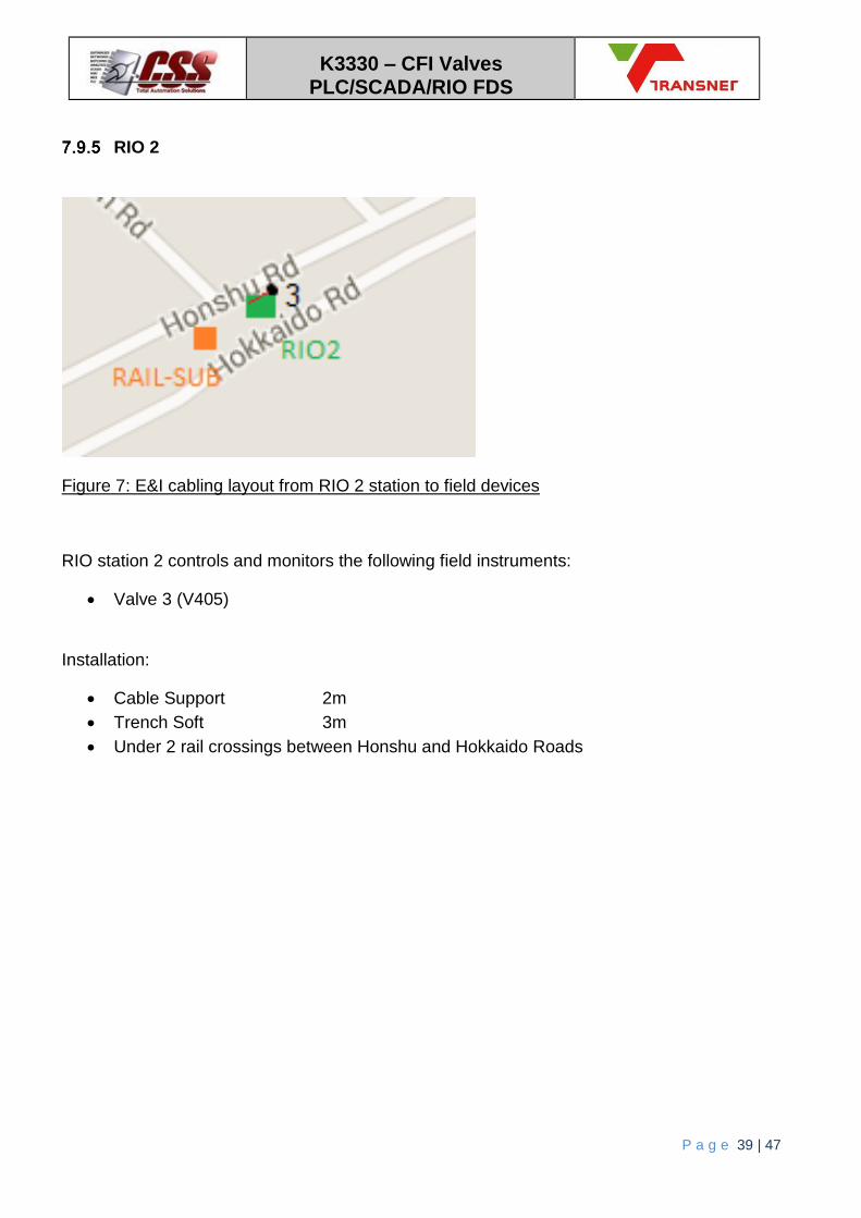
RIO 2
Figure 7: E&I cabling layout from RIO 2 station to field devices
RIO station 2 controls and monitors the following field instruments:
Valve 3 (V405)
Installation:
Cable Support 2m
Trench Soft 3m
Under 2 rail crossings between Honshu and Hokkaido Roads

K3330 – CFI Valves PLC/SCADA/RIO FDS
P a g e 40 | 47
RIO 3
Figure 8: E&I cabling layout from RIO 3 station to field devices
RIO station 3 controls and monitors the following field instruments:
Valve 5 (V504)
Valve 15 (V501)
Valve 16 (V505)
Valve 17 (V419)
Pressure Tx 4
Installation:
Cable Support 10m
Trench Soft 323m
Trench Hard Gravel 48m
Trench Asphalt 10m

K3330 – CFI Valves PLC/SCADA/RIO FDS
P a g e 41 | 47
RIO 4
Figure 9: E&I cabling layout from RIO 4 station to field devices
RIO station 4 controls and monitors the following field instruments:
Valve 10 (V1005)
Valve 20 (SV1110)
Pressure Tx 10
Pressure Tx 11
Installation:
Cable Tray 16m
Trench Soft 265m
Trench Hard Gravel 30m
Trench Concrete 8m
Under 4 rail crossings at Taiwan/Abadan intersection

K3330 – CFI Valves PLC/SCADA/RIO FDS
P a g e 42 | 47
RIO 5
Figure 10: E&I cabling layout from RIO 5 station to field devices
RIO station 5 controls and monitors the following field instruments:
Valve 4 (V424)
Valve 18 (V431)
Installation:
Cable Tray 10m
Trench Soft 42m
Trench Asphalt 136m
Trench Concrete 6m

K3330 – CFI Valves PLC/SCADA/RIO FDS
P a g e 43 | 47
RIO 6
Figure 11: E&I cabling layout from RIO 6 station to field devices
RIO station 6 controls and monitors the following field instruments:
Valve 6 (V618)
Valve 11 (SV624)
Pressure Tx 6
Installation:
Cable Tray 9m
Trench Soft 41m

K3330 – CFI Valves PLC/SCADA/RIO FDS
P a g e 44 | 47
RIO 7
Figure 12: E&I cabling layout from RIO 7 station to field devices
RIO station 7 controls and monitors the following field instruments:
Valve 12 (SV1010)
Installation:
Cable Support 2m
Trench Soft 3m

K3330 – CFI Valves PLC/SCADA/RIO FDS
P a g e 45 | 47
Foam Station 1
Figure 13: E&I cabling layout from FS1 RIO station to field devices
Foam station 1 controls and monitors the following field instruments:
Foam injection valves x 4
Pressure Tx 8
Installation:
Cable Support 40m

K3330 – CFI Valves PLC/SCADA/RIO FDS
P a g e 46 | 47
Foam Station 2
Figure 14: E&I cabling layout from FS2 RIO station to field devices
Foam station 2 controls and monitors the following field instruments:
Foam injection valves x 4
Valve 1 (V105)
Pressure Tx 1
Installation:
Cable Support 40m
Cable Tray 6m
Trench Soft 30m

K3330 – CFI Valves PLC/SCADA/RIO FDS
P a g e 47 | 47
Bubble screen PLC
Figure 15: Wireless network from Pressure Tx 5 to Bubblescreen
The bubble screen PLC I/O monitors the following field instruments:
Pressure Tx 5 (wireless communication that is existing via White Light Tower)
Installation N/A.