Embed Size (px)
Citation preview
r.'
m OU'I:EH. SERVICB AT{FLA. Olil 'lHE AIEXAN:DRA PAlACE VISION AND
SOUND TRANSMI~:TEl1S.
Report No', K.07l Serial No. 19h.s/2.
.'

Research Depar~nent
Work earried out by:-3.11. Efu"lardson
SUM)),fbl1Y . -
REPOHT NO. K.07l
Serial No. 1948/2
A survey of the outer service area of' the Alexa.ndra Pala.ce television transmitter has beon completed and a field strength contour map prepared. .
The field oontours have been plotted from the results provided by a s.eries of radial 1l1oasurorncnts·.in eight directions from ,A,lexcmdra Pf.l.lacc and from measurements· made. in principal towns in the al'eo.. The average lirili t of range' for reasonably
. good reco:ption in the absence of interforence or £ading is; about ,0 miles.
The average ratio of the sound transmitter field strength to the vision tranSITd tter field strength wa:::: determined by occDsional sample measurements on the sound transmitter (411,1' Mol s) •
. .A number of short fading records and -ohs.ervations were . made, whioh, vr.i.th tho (lid of ;recent experience, have made it. possible to indio<l.te on the T1l1):l? an approximate area in vmch .fading of various degrees mc,l.:'{ be apparent at t:iJll.es.
Resoi.lIDh reporto 1':.038 [md K.038.2 'iDsued inl938 gave the results of a field strength DurvOY on the A1exrJlldra Palace sound trctl1smi tter on 41..5 Mcl s.
w'ith improved apparatus and better measuring technique, tiho outer servioe [l1'ea has been now re-surweyed, measurements being mado on' t:10 vision transmitter (4-5 Mcl s) out to the 1imi t of the service o.r'0<" nnd beyona.~ This survey is of importnl1cc, since a poat wEtr trehd has boon tOV1£lrdS [1 hrgo increase in the number of television rcceivers in this out~r area.

The measurements were mainlJr oarried out during the radiation or an , artificial hars f pioture signal, although. some were made during normal programme hours. The difference in fiel~strength between the average pioturc signal and the signal when artifioial bars were being ro.diated was negligibly small and n. correotion was oonsidored ncoossar,y.
Occasional oheckmeasuromonts were also mo.de on the Television Sound ohanne1 (41.5 Mo/a) Dnd the ro.tio of vision I'ie1d on artificial bars or, average pioture to sound field was found to be fo.irly well maintainod at 1.25:1. This ratio v,cs 'USed to determine -an c.pproximate figure for the peak wM. te transmitter output, the method being dcsorib-od in Appendix A.
2. g:PABA.rtJS USED FOR ME.ASUREMENTS.
~he mobile moos~ c.pparo.tus 'lisod W[J.S the R.O.A • .3OlB Field Intensity Meter, used with 0. vertic[~lJ.y polarised hall .. wawa cti.pc1e o.erial,supperted by a telescopic mast. The aerial height above ground, for all measurements, v~~s 2~ ft.
Normal teolmique was adopted at eaoh rneasurOJI,lent point. The vehiclE; oruiso.d at on approximate speed of 3() yds/min. ,mu the signal was oontinuously recordeu. by a recording, milliammeter. B~ inspection of the reoorded pattern, it was· possible to determine the mean field strength at the measurement point.
3. RADIAL· MEASUREMENTS.
A series of radial measurements on the 4-5 Mc/s Vision transmi tter was made in 8 directions from A1exandra Palace as follows,:
General Direction
Oambridge Oolchester Foulness Island Maidstone Shoreham-bY-Sea Southampton Bagley Oroft Inton
The averagf) length of the radiala was about, 60 miles, and at the extremities. measuremen1t was: difficult and liable to some error bea.ause of the weak and variable nature of the fields. The ne are at measurt:..'IIlents to AlexonGlra Palace were between 10 - 15 miles, the conditions inside this radius being of 1i ttlc interest as far a.a the objeot of the presont work was, concerned.

t
Du.ri:ng the radial measurement a some speoial observations. were made. These had the object of ~serving the fad:1.ng oonditions at Jehe time the measurements were made, in order-to avoid. taking measurements for reoord' on the field oontour map, when fading; was> )?!'OSC!l;t., At all distances from Aloxandra J?a1ac.e greater than 2.5 miles>, tl1.o rcceivedfield strength waa observed. for a shOI't period. at cac;.b. mea.:ruring site. The presence and degree of:lfading Vlore noted v;hun 1'1eCOSf::iu:c:r. A.t tho exttemi ioy of each radial a l'ad:i.ng· record Vias made, 'i;1,lJ rcoo:.':'dinc period bei:r..[s approximat.el3" one hour. In adclition, [1. cont.inu.ous: fa.ding rocord was lJ.1a.de at Ba.e1ey Croft, Oxfurd, throUf:hvut the "molo measuring period, the .purpor3e of whioh WEtS to give 0. very gener;cll picture of the conditions at any time and particularly to show when fading wan abnormally b:ad. At suoh tih113S, C[1!'C Vl8.S 'caken not to r.::c.kQ measurements ledl, rela.tive~ long clistanccs from tho tranfmi ttol'~
11lroughout the vA'lOle period ef two months. (Septombell,' -October 1947)" the oJUount of :endinS et B£lglcy Croft was nover gre;3,'!;cr thn.:n ± 50$. A greater -degree of fading mBiY' w:ell bJe obDetveci d.uring the sunnier 1nonths" vrhen conditions in the lcwer a'~lllos:phGl'e ma,;Y give greater refrac'bivo effects than at o)liher
The sites used for measurements wore caroful~ selected, As fal:' D.H possiblo 9 open sites? w1::,ic!:L were·free from major. ob~/c:;i.clc8 p,nd possible ref'locti..ng ol01nentD) were ohosen.. This was to ensure thali t!l13 roceiving aerial hoight-gainchar.aoteristic ~Vlould be sub stantially linor~r, as it was desired to convert the mea.sured valLlus D.t 2.0 ft. ibovo ground level JGO values a:1t 30 ft. allOv\,;; gr01."l.nd lcvul. ~Chis is the sJGDJ1da.rd height for ·1Jolevision rocoiving aeria1a, being about. tho [lvel'n.ge for a roof-top aerial. '1'ho stnnding-wavu :po:btexn sot up by nny unavoidable reflections was e1i:llinrdied by the no:cm.)ltcchniC}.'lJo of cruising across the measur;Lng s!.to. Tho stimclin,?;;-wllvQ r.ntio for Dll D.verag.e site in open c9unt r.r W£tS usually of '~ho order of' 1.5: 1 or lesSio
The l'adif:l mensuro;;lonts ho,vc been plotted· as shown in ]1igo. 1 - 8 (~c.), togo·ther with "the ground contour section alonL~ the SD.'1l0 pathI:' The values of fiold strength plotted are not tho-Llc-Gunl' mou:stu'cd v~~lt:os on [1rtificial bo.rs. or a.vcrage picture,. buit havG lwon corrected to the lIpoak Whitetl field wa.luo by raearls of Cl. fDd;or of 10 5'+ dor-lvcc:. IiW$ described.:1.11 Appeniix A • . ~fJ~ondU: A also s~\Ows the nlethod by vlh.tch the approximate walue: of J.5 kW for the pceJc wJ.:d to·brunsm:i. tter output power is derived. Thoy hD-ve also been oorrected for an aerial height of. 30 ft. above eround levol. :MOE:tsuroments which are s1.lbject; to considerable or:r.;orduo to fading areindice.tod by a sepo.rate s;ymbol.

-4--
On the whole, the plotted resulta Show no unusual departure frem the expected values. In oases where the. at'~enuation over hills may appeo.r to be unduly high or low, it, must bs rememhered that the. actual measuring sites are not necessarily situated at the l1icheat or 10we13t points. along the seotion in c;J.uestion. For instance in Fig. 5 the. nttenlIDtion owr Reig~to hill (23.5 miles f'rom'Alexandre. Pal..."l.cc) appenra-to
. be unduly small. The point of high field streneth, hovrever, does. not- represent the hi[)."l field to be. ex}1octcd at the top ot the hill, becausce the nctuo.l meo.surins site is below the brow of the hill and. the signal has alrc.;ady sufferod consideroojlo
'. attenuation.
The use of the radial measurements in the plotting 0:1 the contour map is disoussed under the l..."1. tter headinG.
4-. ~_ME.ASUREMENTS.
In addition to the radio.l measurements,. a. ntunber of t spott field stron.c;th measuremonts,. on the l!-5 Mcls visiolil si[;nal, have been made in the prinCipal tovms in the area. Each town or city was divided' into distriots, the ntunher va.r,yine according to its size, and a recording of the field s.trength Wc;J..S made as the vehicle cruised with its -ncrio.l at; a height of' 20 ft. The results arc,. as before, corrected to a. s:~a.nd:'lrd r€1oeiving aenal heiGht ot 30 ft., on El. linear height gain basis.
Oompariaen of these measurements; with radial measurements, in the area, er with-the field contours plotted on the map (see Seotion 5 (a.) ,below),. show that in many cases the average field. is lower thE.m would be expected. -Built up areas are often located on relatively. low lying ground, or in ava;Lley, and this pure33 geographical effeot contributes. to the increased attenuation. In practically. all cases, hov'fever, there is additional attenuation, which can only be due to the local effects of the buildings themselves, :L. c. screening and absorption. . The attenuation 30 fp.et above Ground ia probabl¥ 10sa than that e:x:perionced at the measuring height of 2:0 llt. 'b.ecausemost buildings do not aorcen a 30ft.aorial aa. much as a 2.01t.a.erial. It is possible, therefore, that inaccurate
. figures will result from a height corre.ction for 2:0 ft. to 30 ft. made on a line.ar basis. The values given in the Appenc1ix are deriwe.d in this manner and rnOS' show a rather lowe.r -walue than is ac:rtuo.l33 0:Jq)erioncod at ,30 :flt. ol>ove ground. Without a very detailed inVestigation, it is practically impossible to improve the accuracy of the method of measurinG at 2.0 ft. and oo~ing, to 30 ft. on a linear heicht gain bt~sis..
, :.t'< ..

-5-
A. field strength contour map 'of the London Telewisiolll ou.ter aervice ar.eas has 'been prepared, using both ~dia.l and town measurements, (Fig. 9). Field strengths are plotted in Peak)m+1ta field. for a receiving aerial height of 30 ft. above ground level.
The radial measurements ~have been used to indicate the position of the fiolcl contours along each radial, and the town measurements have been used to facilitate the plotting of the contours betw·een the radials.
A.s discussed under the heading Town Measurements, (Section 4, above) the :i.ncreased attenuation in built-up areas tends to cause disa.greement between these and other nea.r measurements in districts surrounding the towns~· The correct. procedure would be to insert closed c.ontour loops around the particular area involved, but this method would fulfil no. useful pU!;pose and would only acrve to increase the cOlUplexi ty of the map. The technique adopted has been to regard the averagJa field strengths' in towna as being lower than the ambient. field for the area, by any amount depending on the local topography and the meD.suring si to features. This amount is usually of the order of 3 - 6' db.
Without Lln extJ::'c''Ille.Jy comprehensive survey heing made" a certain Dmount o:li' estbnation must; be. introduced. The. ground profiles or sections on Figs. 1 - 8 9 Vlru:e uaed to estimate the. field atrength contours in places, where measurementa hoo not. actually been made. This method is not qui te so approximate na it lUny at first appcnr since, in most cases, the radial . measurements give a good indication of the general attenuation, to be expected, for a few miles on either side of the radial line.
In the, NoW. quadrant the rising ground towards. tha Ohiltorn Hills produces an elongation of the inner servioe area,. as> also does the rising ground. tovro.rds the South Downs, :hn the South Md South East-. Attonuation over these hills, however,. is very great and the outer area is compressed, producing an IXpparent elongation in the N.E. Md S.W. directions.
The V!Ory high rate of attenuation over the-eastern part of the North Downs is to he partic'ularly noted" together with the r0pidly changing contour gro.dient towards the coa:ttit in North Kent.

- 6 -
The tading area, which has been indicated, is one in which serious fading may be apparent at times. The location of the boundary of this area was detenuined with the aid of the observations made, as well as recent experience of faGing phenomena. It is inevitable that substantial tolerance must be placed on the position of this boundary ~ because of the very variable and unforeseen
,conditions which may exist at certain times. On the whole, however, 'it may be said that the area. shown cross-hatched on the map is l;Lable to experience various degrees of fading f:C'om slight to serious whilst in the unha tchcd 'area :Cading will be generally either slight or absent. ~
(b) Town M9~.om~nts.
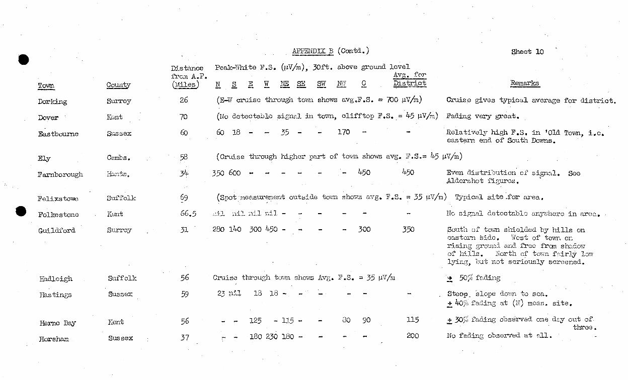
The table below gives the ,wer~lgG field strc;ngths measured in each of the tovms named. Since in some cases there is considerable vElJ.iation in field inside the tovm, more detailed results are tabulated in AppondixB, ~~lich includes notes on the effect of loc~l topographico.l featureso The greater detail in Appendix B may be of use in rGlatiol1 to reports received on the subject of television reception.
~, younty !:Y!EEJ:10 1!'. § oe ; • .(?.£.Ei,!::o ~Wh2-te ) for District --
.Aylesbury Bucks .. 110 pV/m Aldershot Hants. LrSO !lV/m Bailingstoke Hants. 200 fJ.V/m. B:edford B'eds. 100 pV/m Oambridg@, Oambs,. 60 fJ.V/m Oanterbury Kent 70 pV/m CheJmsford Essex 600 pV/m Darking - Surrey 700 pV/m ElJr Cambs. 45 fJ.V/m Farnborough Hants. 450 !lV/m Guildford Surrey 350 ,N/m Hadleigh &uf'folk 35 1ivjm Herne BaY Kent 115 flY/m Horsham Sussex .200 lclV/m Leatherhead Surrey 700 !lV/m Luton Beds. 900 /lV/m Maidstone KenJe 280 fJ.'\t/m Northompton Northantse 40 pV/m Oxford Oxon. 70 pV/m Reading Berks. 180 \lV/m Reigate Surrey 1000 IN/m SevenOP..ks : Ken·1; l,500 lclV/m Sout hen o.-on-Sea Essex 400 lclV/m

SuGIbury Thame Tonbridge Tunbriage Wells
Suffolk Oxon. Kent Kent
- 7 -
~ras.a F.S •. JJ?ea]<: white) for Distri£t
110 ~V/m 160 ~V/m 2:30 /lV/m 280 pV/m
For Ashford, Brip;hton}-Bury st. Ec1munds, ColGhester, Deal, Dover, Eastbourne, FelixsJcowe, Folkestone, Hastings, Ipsvvich, Portsmouth, Ramsgates a.nd Southampton aeeAppendix.
In the abaence of interference and fading effects and with modern receivers a peak white fi01d-strength of 100 /;lV/m vlillgive a reasonably good picture. Referring to the map, Fig.9 it will be seen tha-c the range for this, field strength is from 35 -60 miles approXllaate~ the average being about 50 miles.
(H.L. Kirks)

, - 8·-
(a) Conv.e~o,i-~_ of mo_asl1E!li!.-l}_~_~~_*f3~ren~lL"t2....f..e.8;k White. field strenr?ths ~"","" .... __ ~_ ..• ~_o __ _
Fig. 10 shows cliagrui1lIl1.Dtically t:10 transmitted WflV'(; forms o:fl' an r artificial bar' pioture signal.
t~l the
and (b) are tronemitted v.ravefonns for artifical bars. is transmi ttod for 80~ total time, is tran$1Uitted for 20/6 total time, effect of the fr~llP.e synchronising pulse being negligible •.
At. Receiver: - ". -Referring to peak white as unity, and "vi th a "linear"
detector.
Average detector ourrcnt:-
(a)
(b)
;;: (0.3 x 0.22) '+ (1 x 0.68) ;:: 0 .. 1-4:6 .
;;: (0.3 :le: 0.9) ;;: .0.21
T.otal avemge cur'rent:: (0~27 x 0.2:) + (0.7lI-6 x 0.8) ;:: 0.651
Hence to convert measured liltS. into pef ... k whi-l;c multiply' .'j;ly
Measuremonts shoW that, at [1.n overa[:;e receiving site, If F.S. due to }.j-.l.5 MO/s (Sound) ;:: 1 mV/m t~1en F.S. duo to 45 MtJ/s (Vision) (Average picture);:: 1.2.5 mY/m •• Peak \iVlli te F.S. (Vision) :: 1.925 mY/m Sound t:'.'r..nsmitter power into feeder::: 4. kW (infonnation given ~7 AlS.J::. Tel.) ~ •• Peak White power into feeder;:: (4 x (1. 2 )kW
. ;:: 1?J~~ (Ass~aing aerial gain, feeder loss and propagation
characteristios Cl.re eq.ual ~or sound and vision) Sto.ted pOlllor for A.P. vision::: 17 kW POl!lk vVhite into feeder Meo.sured powex' ;:: 15 kY'l Pe[l.k Whi teinto feeder.

~IX.B
e Distance Peak-Wm. te F /S (!lV/m), 30 ft. above ground level. Sheet 9 froml\..P. ~vs;.for
Town Oounty (11iles ) N §. - E W NE SE SW NW C District Remarks - - -Ashford Kent 53 5 35 18 10 Si tuated on sloping groUna. (away frora
A.P.) and shielded by N. Downs.
.Aylesbury Bucks. 33 115 120 120 110 Cruise across built-up area confirms average.
lldersbot Hants 36 570 350 350 It-50 Fairly even distribution of signal. (Compare with F~nborough)
Basingstoke P..ants. 47 - 200 60 140 200 200 C\T) point is on low ground behind major part of tmm, otherwise signal is fairly well distributed.
Bedford Beds. 40 90 115 100 SiO 90 100 Signal evenly distributed, low lying land.
e Brighton Sussex 52 .. 5 -115 18 25 170 18 160 ilell out of service area, but bas high land in places with relatively high JP.S. Much fading.
Bury St. Eclmu(l(lS Suffolk 58 25 18 - 35(c) .,.. 25 + 50% fading.
Oambridge C3mbs. 44- 8O(ss )- 70 70 60 60 Vc::cy flat country .. signal evenly distributed.
Canturbury Kent 56 - 70 70 60 60 60 70 Even distribution of sign&.l.
Chelrasford Essex 27.5 600 530 700 600 600 Even distribution of field.
Oolchester Essex 48 60 nil 125 45 No detectable signal in fC ...... end would be inaccurate to state an average field for distriot.
Deal Kent 71 60 40 25 1\T ..... eno. better because of better path.
Distance fro:n A.P.
Town County (lVIileJ0
Dorld.ng Surrey 26
Dover Kent 70
Eas tbou:rne Sussex (fJ
Ely C.9Jllbs. 58
Farnborough I-iants o 34-
Felixs tm'VC Suf'folk 69
e Folkestone Kent 66.5
Guildf'ord Surrey 31
Haclloigh Suffolk 56
Hastings Sussex 59
Herne Bay Kent -I" )0
Horsham Sussex 37
APPElIDli B (Contd.)
Peak-Vihi te F .S. (/-lV/m), 30ft. above ground level Avg. foT'
C District -,--.-
Sheet 10
Remarks
(E .. Jif cruise through tovrn shows avgoF.S. = 700 /-lV/m) Cruis.o gives typical average for district.
(No detectablo signal in toitvn, cliff top F.S. = 45 /-lV!'Il) Fading very great.
60 18 35 170 Relatively high F.S. in 'Old Tovvn, i.e. east~rn end of South Do¥ms.
(Cruise through higher part of town shows avg. F.S.= 4-5 /-lV/m)
350 600 4-50 4-50 Even distribution of signal. See Aldershot figures. '
(Spot I'lO£csurement outsia.e tov\'Il shows avg. F .S. = 35 /-lV/m) T".fpical site ,for area.
280 14-0 300 4-50 -
Cruise through torm shmirs Avg. F.S.
23 nil 18 18 -
125 - 115 - 80
,.. 180 230 180 -
300 350
= 35 /-lV(rn
90 115
200
110 signn.l detectLble anY'Vlherc in area.
South of tovm sbielded by hills on eastern side. West of town on rising groUl!.d and free from ShD.doVl of r.d.lls. North of town fEcirly low lyin,s, (Jut not seriously screened.
. 5rJf fdi '+ Ola L ng - .
Steop. slope d07m to sea. ~40% fading at (N) meas. site.
o~bserved one day out of three.
No fadi..'1.g observed at all.

Distance
e fromA.P.
~ Oounty Qiles)
Ipswioh Suffolk 54-.
Leatherhead Surrey 22
Luton Beds. 23
Maidstone Kant 36
Northampton Northants. 5'+
Oxford Oxon. 50
Portsmouth Hants. 68
Rams gate Kent ~9
e Reading Berks. 37.5
Reigate Surrey. 24
Sevenoaks Kunt 25
Southrunpton H:mts 1]1.5
Southernon-Sea Essex 36.5
SudbuI"'J Suffolk 48
Throne Oxon. 38
Tonbridge Kent 32.5
Tunbridge Kent 35.5 Wells
------
Peak-Wm. te F /S
li .§. E W -18 nil nil -
- 800 -460 -- -
320 460 160 230
50 70 25
.APPENDIX :i3 (Oontd.) . (~VAh), 30 ft. above ground level.
NE SE NW o
10
- 1150 200
- 180
35
Avg. for Distriot<
700
900
28G-------
45 115 90 160 55 18 70
Sheet II
Remarks
±50% fading
Cruise through tov.n oonfirms average F.S.
High ground to NE end of' t01:1h shows highest F/S. Much fading.
20 nil ni"J. (Portsdown Hill F/S = 85 ~V/m at highest PO:ll1.t) .±. 509,~ fad:L'1.g
30 18 - 70 30 -
180 90 320 180 180
(2 mile. oruise thro'ugh district Avg. F/S :: 1000 ~V/m)
1000 500 2000 1500
18 nil nil nil -
Sh&rp attenuation gradient from ooast.
N~·J. is point of lowest F/S in area (Riverhead)
" Signal only detectable in N. of tOVID
(Avg. for district:: 400 /-LV/m. Min:i.m.um ]'/8 :: 150 /-LV/m (by. coast) 400 /-LV/''YJ. figure derived from open count~J measurements.
- 100 120 110
(Oentral Cruise through wide main streets shovlS e.vg.F/S = 160 !lV/n.)
(Central cruise through built,;"up area shows avg. F/S = 230 /-LV/m) LoVl lying built-up area:
- 180 - 460 160 - 500 460 280

~~e two transmitters, sound and vision, at,Alexandra Palace D.re connBci;od by moans of concentric copper tube feeders. to two separate, vertically polarised aerials of similar design, the vision aerial being situated above t~'1e sound aerial on a self sUPliorting lattice steel mast 300 f-l:i. in height.
lioth the aerials eonsist of eight al~rays disposed around the lilD.St so as to give [)J1 ap:?roxjlnately circular horizontal polar diE1gram. Each individmll arr::w consists of a stack of two vertical end - fod hnlf-vnwe cnga element;] spnoed a quarter of a w[1volcngth in' front of a pair of simik,r elements acting as: driven reflectors and intended to reduce the lassos in the steel mast.
The eight arra;)rs of re.die,tors E'J1d reflectors are fed :Ln parallel and the vihole asseml)~, in the case of both vision and SOUlld, is ap;'Jroximd,;cl;;r equivalont in peri'onnance to two half'·'vD.ve verticeJ. dipoles, stacked one [lbove the other? with a spacing of sliL:htly more than half El. wavelength between centres.

ISSUE 1.
l.6-S-48
'BBC
100
so
80
.70
l ~ ~ ...
tU 60
~ W Ol 11.1 i:J 50
et .Q ."
40
30
2.0
aaJ
2d c(~
.J
ti< ~ILI lLlIl
-- --t-- t---
--~--t-- -t~ I--+---+----"t---!--i~-f---"--+----+-----t-+--l---+-,.--+----+--r-- ---+--
-- ------.,----------,
FIELD-STRENGIH & CROUND SECTION
1--t--+--t-+-frTfF,-i'-+-+-; +f~-rrt-+-r--+-~ BETWEEN ALEX.PALACE & CAMB121DGt
!', . . i
l .Ii . li 'I :1 +"T
1 --t- --r
l,. "-+1: -,.-'. -+i-· .:...ill--l FREQUENCY: - -- - - - - - - - 45 Mc/s " j HE:IGHi OF R.ECE.IV1NG·
TI<A.NSMITTER. OUTPUT PoWER: 17kW PEAK-WHITE I AERIAL ABove: GR.OUNO;-- 30.FT. . 100'MV/", i i ' AERIAL. INPUT POWE2: - -'- - - - I .TRAN5MITT!:R SITE. He:.'C.HT~ 3~F"T. d:s.l.
HEIGHT OF TRANSMITTING i TRANSMiTT1NG A..Ef2.IAL.;:---SPE.CIA\,. ARRAY I .' . AE.~IA.L.. ABOVE CiRC)UND:-- - 2SO FT. i POLA2.IZATION·:- - - - - - VE~ICAL.
1------ .- --r-
I
I
\ 1
\ i I 1
\ £ ~ I
\ I I v E) 0. 1 i
~ ~ ~ V ~ .. I
~ I i
I I
1 ) ~ ~ I I , I I I
10pv/m
.~~~
'/
600
400
Z .. "
0
FOR.M Re 5003.
DS/28/0C -~--'---------------------------------------~-------------_._-----

•
BBC
80
80
.70
l ~
=\ -lLI 60
~ W Cl
,ltJ I ~ 50
lot
FIELD - 5TRENG I H & CROUND SECTION, _-+--+---1 BETWEEN ALEXo PALACE & WLCHESTER BEARING 65·
~+--+--+-4--+-+---+--+-f--+---+--I---+-+-+--I--+----l-~ FR.EQUENCY: ~ - - - - - - --T~NSMITTE2 OUTPut POWE.R:
45 ~e/s I HEIGHT OF R.ECE.IVING 17 kW PEAK-WHITE AERIAL ABOVE GI<.OUNO:-- 30 n:
~!!~§ggt~~~~tt~~~~t1g~~~~~~~~~W~:-----l= HEIGHT OF TRANSMITTING I--+--t--+-:--t"--+--+---+--+-I--+---+---+-+-+--+-jr==t::j~~~..:j AE~IAL ABOVE CrI<.OUNO: - - -
I, TRANSMITTI!:.R SITE. HE.IGHT: 300 FT. a.s.l. I TRANSMITTING AE.RIAL.:- -SPE.ClAL. A2RAV ,
Z,SO FT. I POL.AR.IZATION:- - - - - --'- VER.TlCAL. I
~-+---+---+--+----'I--+-+----+--+--f--+--+---+--+-I--+--I--I--I----I '--+--+--+--+-+-i-+-.-.. -+---+--+---+-'--~+--I---+--+---I-+---I-~ 0 OE.NOTES PEAK-WHITE: F.S. ORIGINALLY MEASURE.D ON DIPOLE 2.0' ABOVE GROUND
LEVEL t COR.RE.CTE.O FOR. 30: r..
~-+--+---+--+--I~~~+-"-+---+---1I--+--+--+--+-~+--l--+~~ • DENOTES SIMll..AR VALUE TO ABOVE, BUT SUBJECT TO E.R-ItOR. DUE TO FAOING.
I I (V rt FIG. 2.
IDmWm~~~~~~~~I3F\~~~~~~~~~~~~~~~~~~~~~~~~~~~~~~~~~~~~~~~~~~~~~~~j§~~~~ !
\
i
I I
1 I I t I
.1---
,
I----+--+--+-- ,- ---t--+--ir-+--t--+--+-+--+--+--+--I'---+-+-'-~i-- --1 ~- i - - f--\----I-l~-f-,' --+-+I--+--..,f-- --+-f---+--+---+---+,. ---il._~+--+--+--I--+--I - ~-
10)4 V /m.~f--_.-~li~·~~II· ~~II _-T.l...
i _c=.!...~_ .. __ = j' _·-:I:~=~=_'-",,<--_~+-_~~~~~~~~~~-...I-· ~--I·--.JI--II....· _~l...;-_iJ-:~ _' J....--_--l~1 _tJ-: _;J..,--_---iJ..~_l~~\)~·~~~~~~r~-..Lf_~.l.f_i..L'-_--..l.I_--..L' C--_··--J.I_--...J.-:_----J.:_·.J---l~.J+-!f-_:.-~--4:~_ ..J:=-~-j_-..J-lL..-~--lL..'-_~ L..I-..J-4
OS/28/0C a.--. __ ~--," ________________________ -______ ~ __ - __ ----

1~~Vt:
1. 2.&-5-48
BBC OS/2B/OC
80
.70
1 3-~ -~ 60
1iJ, Ol I.aJ :"50 ~ .
.0-'"0
60
-1---1----+----.-+----I FIELD - STRENGTH & GROUND SECTION ~~~~=~~~~=~~~~-_~~~~~~~--~~~~-~_~B~WEENALEX.~L~E & FOULNESS 1. B~I~8~
FREQUENCY;--- -- ------TRANSMITTE5! OUTPUT POWER: AERIAL. INPUT FOWE2: -- - - -HEIGHT OF T"ANSMITTING AER.IAL A60VE C.I<.OUNO: -- -- -
45 Me/s HEIGHT OF RECE.IVING 17kW PEAK-WHITE AE.RIAL ABOVE. GJ:roUNO:-- 30 FT.
280 F'T.
TRA.N5MITTE'.R ~ITE. HE.ICaoHT: 300 FT. a..s.l.
TRANSMITTING AE/:aIAI..:-- SPECIAL. AR.R.AY POl-A.~IZATION:- - -- - -- - VERTICAL.
~~~~~~4-~-~~~~~-~_~~_-~~_~ __ ~~~~0 OEN~~ FEAK-W~TE ~S.,O~~NAL~ ME~UREOON ~PO~ W'ABOVE G~UNO L.EVEI.. I CO""ECTE.O FOR 30',
~-+--+--+-+----+---+--+-+--+----+--+--~+---+--+----1~-+--+---+----I. OENOTE.S SIMILAR VALUE. TO ABOVE I BUT SUBJECT TO ERR.02 DUE TO FADING.
FIG. 3.
J----+--+----l-+___ -J-\.- --- -----!-::~.~f---+---+-I---'---+-----+--~+---+- f----- ---+---+--+-+---+-----+---1---+---+---1--- - -- --~---+--+--_+_---+---+---I____+-+___+__--+-+___+__--+-+_____+___+___t -IF. ~ I
--- "'~ -- r-- --- - ---+---- --I----- --+---+---I--+----+----+-T-+-~-+--+--+---r--+---+--I I-----+---+-+----+--+-+---f--+-H_~--(~---I---l---+-------l,--I---+------l----II---+---+-----I,--+--+------<I--+----1---1-- ~ -- - ---- --- ___ ~---ii----4-----!---+-~---_ -1---- f---
l~v;m~~=i==~~=t==t=~=t~t=~~~~t=~=--i-==---t-=---.~~=---j-==t==t=i==1==t~=:1==t~·t-=1-I--==-t==--E--=i-=:-t"==-E-=-j'=-=t -==-'-E=3-== ··t==t~==-·tl-----=:t~=--3==1··=-=-t~=--3=-=--~=t~==~3 r..: --~ - T • _ -, --=- .. --f::~- - ------I=::=~~ ----~-1---1__ .-~ .---- ------:--- -- -- -- -1-- >--- -- ------~~~~~--t-~--+---t--+---!---~-+-+\+--~-4--~~~-4--+---+-~~--+--r-4--+-~-4-+----~- T--+~r--+--+-; ~-t--+--~-t-~~~-t--+--~~-+-4~~-4--~-P~,~----t-~--~~-+--+__-I----t--~-+---t--+-~-4---+--I--
,-~ ). .
h
DISTANCe: FROM TRANSMITTER - MILES. FOR.M Re 5003. RESE.ARCH DEPT
R.EPOR.T
K.071·3 10 SHE.E.TS

ISSUE 1.
2.6-5-48
•
BBC DS/28/0C
-----= -------= -----= = ----
100 1-= = ..:: ---
so 1-::::
= -= .-----,-= 80 ----= -= -I":::: .70
l ~ ~ ....
= -.= --= '-= = = = -,-= -=. .= = = o 40 '-:= = = --= ,....:::; 30 = = ~ ~
......:;::j
I
I
loo'l'l'\v/m f-- ,--
10mVjm I-- f--f---t--
lmv/m
l00 ...... v/m -----' ----
-+--i
10;"v/m I
~
4 -, C
-~-f--- ---'- f--~ -
I
f---
,
0 __
1-(0)
\ r-, f / \ t- \
M' \ fi
• ,,- ---f..--\. , 0
7 \ 17
0 , -.
I - I
i I I I
- 1------ -- r- --' --- -- ---- --- --1-._-
-----::j:-'--- --: 1--+- ---- ---- ------- ----t- ---
---~---- ~---+----- ----+--- I ' --- ---~--- ----- i--------t'-----+ --1--
-+-+tt+~~ :---- ----+---1------L- ---
-+-1-- -- -1---+ -t----l--t--L-----I---! I I I i I lit I i ,! i
.
I Cl) I
~
'O~_ "!= ,r
1
~ -~----- ------
FIELD - 5TRENGlH -& CROUND- SECTION ,
BETWEEN ALEX. PALACE & MAIDSTONE BEARINGt2 I
_ FREQLjENCY;-_--------,- 45 Mcls HE.IGHT OF RECEIVING T~NSMITTER. OUTPUT POWE.R: 17lc.W PEAK-WHITE AEJllAL ABOvE. GIWUNO:-- 30FT;
AERIAl.. INPUT POWE2: -- - -- --- TRAN5MIT'TER. SITE. HEIGHT: 300 FT. Q..s.L.
HE.IGHT OF Ta;aANSMITTI~ TRANSMITTING AE."-IAI..: -- SPECIAl.. AR.R.AV AE.RIAL ABOVE GIC.OUNO: - - -'- zeo FT. POLAR.IZATION :->- -- - - ~ VERTICAL.
--0 OE.NOTES PEAK-WHITE F.S. OIlIQINAL.I..Y MEASU2ED ON DIPOLE 2.0' ABOVE G20UND
I..EVEI.., C02R.E.CTEO FOie. 30', • ·DE.NOTE.S SlMILAR.. VAI..UE TO ABOVE, BUT SUBJECT TO ER.R.OR. DUE TO FADING-. -
FIG. 4. . -
- --
I' - -
-
-
I I . -
-- =+-~ -- - - -=t== i--- - - =-.....:
~.,--- - -- -...;.
\ I"\. 1
\ j __ ! D I I \: \1 i i !
-~ f,--___ ~I __ +--- - - ,-
\:., \ , I ~
I. - I ~i ~
I I ./ ..... I i I ! .......
- -.:.1=- - r'::$::-- _--t: --r--'-~ -.-f-- .. -- - ---- -- -+- -." --=--t-~=t: -c--:- --+--- -- +- - -.~ -- f-- - ---- r--
1'- -. --t--+--- ,-~---_t---,--- '--- ---I +-1-- ~v._ -+---J-- --t--1 e--_ --- -----t ' I i - ----- +rtf+- ---I---+-~ .-- -
I 1-----1-- -+- j - I ---t-I --'--- --- -- --T---t I --t--f----f--- ---+----
I I I I I I ! I I 1 I I
~ l~ ,
r i 1 p !
~'"" --;;,;; ,
eo eo 10 110 :510 i' )0
DISTANCE. FROM TR.ANSMITTER - MILES. FORM 285003. RE.SE.ARCH DEPT
REPORT
K.071 · 4 AP'O 10 SHE.E.TS.

ISSUE 1.
26-5-48
---t--- - -:::.E~ _+ J ~ f- +-=--= I-+--+----i-+-+--+---f---+--+--I -- ----r---,---- t----t--I----+--+---+--~+--- ---t---+---~ -- -- -----t-- ---I----t----
---'r I -ii'. -_'L.t--+--+-- --- --l---+---1-- ---+--+-+-----r----I--t-+-. -J-,-+----J..--,- -- i---- --- ---l-l----!---_+_ +-_.--1---i , I t: I I ! ---t- -1-- - --+-- -t--~-l---+-- ----l-t--t---
100 mY/m i' I I I I I • --j-.-l---- .--- --- - --- -------- ----+---+----t--- _=--___ I_-:::.t---_~t:--:t---=--= --±--:
1--.-;----+-----+---'- .---<f---+--+-----+--\---+-~---. i---- - 1---1---i-----t---1~--t--
~~-----------------------------
FIELD --STRENGTH & GROUND· SECTION BETWEEN ALEX. PALACE &. 5HO~EHAM-BY-SEABEARINC 1870
FRE.QUE.NCY: --- - - ---- - -c- -- - -- 45 Mc/s HE.1GHT OF RE.CE.IVING TRANSMITTE.R OUTPUT POWER: 17 kW PE.AK-WHITE AERIAL ABOVE. Ci-ROUND:-- 30 FT. AE.RIAL INPUT POWe:.2:-- -- -- --- TRAN5MITTe::R SITE. HEIGHT: 300 FT. Cl.e.1.. HE.lGHT OF TRANSMITT"~G . TRA.NSMITTING AE."IAI...:- --- SPECIAL ARR.AY AERIAL AOOVE. c,.ROUND: -- --:- - 2.80 FT. POLARIZATION :-- -- -- -- - -- VE.R.TICAL
1 I. - I-----t---t---- -- --f--"---f--"-_-+--+---t----- ~~~C~-F--.- 0 DENOTES PE.AK-WHITE. F.S., ORIGINALLY MEASURED ON DIPOLE. 20' ABOVE. GR.OUND
, LEVE.L.., COR.RE.C.TED FOR. 30'. 1---+--+---1-+--+--+-+---+--+- --I-. -I------+-+----i--~. OE-NOTE.S SIMIL..AR VALUE TO ASOVE., BUT SUBvE.CT TO EI2.ROIZ. QUE TO FA-DINe-.
FIG. S.
DISTANCE. FR.OM TIC.ANSMITTER - MILE.S r-------~----------------------------------------------------------------
FORM R 8 5003.
~_ RE~~ARS:ti DEPT
BBC DP.:~I . REPOIZ.T. 1
Ci~-'D . K. 071 · 5 I ~P'D rP~ . 10 SHEETS J DS/2B/OC ~-~~~~~~~.~------------------------------------~----------------------~~-------------------------------..

ISSUE 1.
2.6-5-48
•
BBC
= -= --.-=
- --j-- - '--.=-- =-1=:--+=-+----1-----+--4-...... J..---+---+--++-----II----'r, -+---+-,-L=~t=::t~j-~~.t_::-j_I_-_+-,_+_, -------4--+-'-=---t-=.:t==t=1=j
I, . ! FIELD-STRENGTH & GROUND SECTION
I t---r-----t-----t--t--t--T--i~t--r--+-+--t_-_t__+_+-+___t_-+___+--4____+_-+___f-·-+____+_____+___+-__+--+____+____+___f-+___--+--__+----+-+---+-__+--I-+---+---+---+-+----+--+--+-+___1
1-(.
"
DISTANCE FROM TRANSMiTTER - MIl.E.S.
I, i ! !
DS/2B/OC --'--------'-----, ------- ,. --

ISSUE 1-
2.6-5-48.
•
BBC OS/28/0C
100
80
.70
l ~ ~ ....
w SO
~ W Cl w f:J SO ot .0
" 40
30
20
000
FIELD --STRENGTH. & "GROUND SECTION BETWEEN ALEX. PALACE & BAGLEY Cr20FT . BEARING 2&)~ F~EQUENCY· 45 ~ c/s HEIGHT OF RECEIVING
17kW PEAI<-WH1TE. Ae:.RIAL ABOVE. GROUND:----·30 FT.
zeo FT.
TRAN5MITTE:R. SITE HEIGHT: 300 FT. TRANSMITTING A.EJ2.1AL..: - -- SPECIAL ARItAY POLARIZATION:-- - --- - - VERTICAL
DE.NOTES PEAK-WHITE F.S., ORIGrlNAL.LY ME.ASURED ON DIPOL.E 2.0' ~SOVE GROUND L.£VE\.., CORIl.ECTE.D F'OR 30', '. '. OENOTE,5SlMII..AR. VAL.UE TO A80VE, BUT SUBJECT TO ER.ROR DUE. TO FADING .
. FIG. 7.
_ . --I-- ----+-. --+-f-__ ----+ t=f-- --- ---.=I=::+-=t-~:-:::~~~l-:··~f:t::.:~:i ~- - ;--- ~= .:~:.t ... ---: .'-=--=.-- ---, . :t--::- - ----+----+--+-+---1r--+- t----t----+--+---+--t--+- -"-. --f.-- --t- -----+- =::r· i--- -- -- - -+- --_. -f--- -- +- .. c-__
~-I---t---+-~--.-ir---I---+--+----1'--+--+--+--+-~~+--+-.-+--+~, +---+--+--+--j.--+--+--+--+.--t--~-.- ----+----+-- ---+ .-- '--f-~ --t--- ----r---r-+.--r--, I + ! ' . I I '
::=:_:::::::-:~:::::::::::::_-+-~~:_-+~-·--+-f--I-=-]--1_'--_-~.J-----l--f-_--t--f--_-+·t_ -t-+_ -+-+--++--_ -+ff-::: -----::It,T=-I~ ==S-trI,-f~~IC re I I i I I ,. I i .• I !,
~ I I
lJ ~ I
I ,
~ 'fJIA itA If. .rt? ~/J
;o~ Wf:I ~ 0 It: AI, ~ WM ~~ ~ w ~~~~ 1111/, 7Jh...
~o ..".. Ih W/;J, ~ 1'>. '!In W~ WM f1ff~ W.tX: W/@, W~ W~ ~
= EO 70 50 10 '0 ~o
bISTANCE. FR.OM T~ANSMITTER - MILES. FORM R85003. RE.SE.ARCH OEPT
~--a--:.--..........-:----' --REPOIlT
K.071-7 AP'O 10 SHEETS

ISSUE \.
i!6-S-48
e .70
l );-.'-.-
IIJ 60
~ &&J Cl I.LI :tJ 50 Dt ..0. "'0
40
e
. zo
BBC
._._------_._--_._------------------,
FIELD - STRENGTH & GROUND SECTION 1--+--+--+-+--+-+-+-+--+----1---+-+--+--1----1--+---1--+----1---1 BETWEEN ALE.X. PAl-ACE &
, r--+--+--+----j:..--+--+--+---+-I--+--+---l----+-f.--l---I---+.---l-+---I FREQUENCY: - - - - - - - - - 45 Me/s
TRA.NSMITTE.R. OUTPUT POWE.R: t7 kW PEAK-WHITE
~m~~t~~~~t~~~~t~~~~t~~~~t~~~~~~~~T~Wm:-----1= --f- .. +--+---f-,----+ HEIGHT OF' T"ANSMITTINCi t--t--+--f-t--t--+--+-t--f--l--+-+--+--+---+-+--+--+---+---I AERIAL ABOVE GR.OUND: - - - 2.80 FT.
LUTON BEARINC32.S HE.JGHT OF I<ECE.IVING A.E,gIAL.. A80VE. C;"OUNO:-":' 30 FT. TRAN~MITTER SITE.. HE.ICHT: 300 FT. a..s.l. TRANSMITTING AE.I2.IAI..:- - SPE.CiAL ARRAY POLAR,IZATION:- - - - - - VERTICAL.
t---t--+-+-t--t--+--+--,-+--+----+--!~=t-. --Hl~-+---~ {~iL-+~-,-.lt--J.----l~-I-_+__+_--iI---l---i---i---.-+___.: I--I---I-.-+-f-----l---t----+~---.+__+-_+_--+-+-_+__+__+-+___+__+___+'-+__I -·'MI . ~~I I ---1:-'--' -11'-;--+-..,.-+.......,+~t-t,d ~! ---~~ 1\,- i -T ~ ~~-+_= ____ tt_ =._-t
1OOf'\I/",t---f---+-+I-i-+--+---+-+--+--+---+~'-'Hl--~-+----+---l-1 --il....l· ~~-.:... t;. ~r·-....,.,I~+--+--· ~ T+--+--+ 1
1
-----1----+ 11----1r-+--+--+----1[I-.--+-I--+---+--+-I---+i ---I~+---+---I
- - , - .I--f--. ~ .' . ""'"'f .+>or,-+---+--- i-.-'--t----+ __ .-_+--\_. -+__+-":"+---+---+--~f---+-----+---+--l--'-:'+--+----+----1r--1
__ I. .. -r-.· -~-+----+""'~--~-~---+-·-Tt-- ----+---+---+--+--'--~-+.--+-__+-----'~+-+--+---+:....--i__--_+__+__+-I--+___+__I
-+--+---+---il----+---+---+-.-+--~--+-
100
DISTANCE. F'ROM TRANSMiTTER - MILES. FORM R85003. RESE.ARCH DEPT
DS/2B/OC -.. ........ ---'-----------------------------------------------'--------...


ISSUE 1.
2.6-5-48
BBC
APPENDIX A.
100% ------,
% MOD.
!--, ~,
o -L_-'---_____ ,I..-,
106 34 16 34 10 6'
~----100------;
% PE.RIOD
~-----tOO---~
~O 90 _101
FIG. 10.
(a)
(b)
R.E:.POR.T
K.071·10 10 SHEETS.


![The Employees State Insurance Act 1948 - ... State Insurance Act 1948... · THE EMPLOYEES' STATE INSURANCE ACT, 1948 ACT NO. 34 OF 1948 1* [19th April, 1948.] An Act to provide for](https://img.pdfslide.us/doc/110x75/5aa59b087f8b9ab4788d5d44/the-employees-state-insurance-act-1948-state-insurance-act-1948the-employees.jpg)

![Factories Act, 1948 - Jharkhandshramadhan.jharkhand.gov.in/ftp/WebAdmin/documents/... · THE FACTORIES ACT, 1948 ACT NO. 63 OF 1948 1* [23rd September, 1948.] An Act to consolidate](https://img.pdfslide.us/doc/110x75/5ebaa0b53dd9ea6e29246951/factories-act-1948-the-factories-act-1948-act-no-63-of-1948-1-23rd-september.jpg)