Embed Size (px)
Citation preview
MGS® Speed Reducers V.2584 www.stober.com 800.711.3588
MGS®
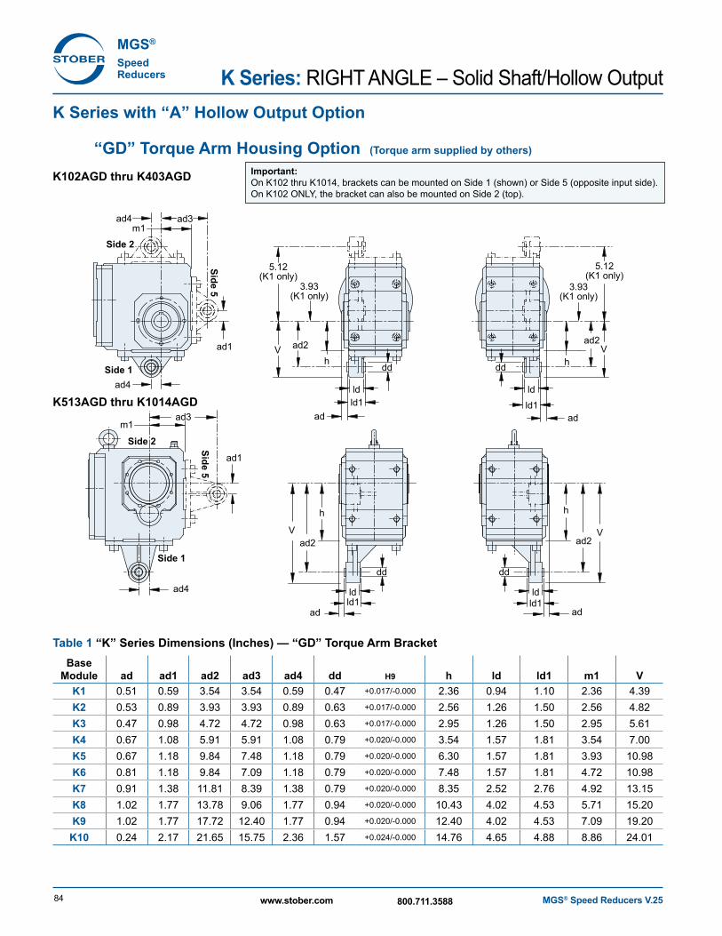
Speed Reducers K Series: RIGHT ANGLE – Solid Shaft/Hollow Output
K102AGD thru K403AGD
K Series with “A” Hollow Output Option
“GD” Torque Arm Housing Option (Torque arm supplied by others)
K513AGD thru K1014AGD
Important: On K102 thru K1014, brackets can be mounted on Side 1 (shown) or Side 5 (opposite input side). On K102 ONLY, the bracket can also be mounted on Side 2 (top).
ad2
h
dd
ad
3.93(K1 only)
5.12(K1 only)
V
ad2
ld1ld
dd
ld1ld
h
ad
ad2
h
dd
ad
ad
3.93(K1 only)
5.12(K1 only)
V
ad2
h
ld1ld
dd
ld1ld
V V
m1ad3
ad1
ad4
ad4Side 1
Side 2
Side 5
m1ad3
ad1
ad4
Side 1
Side 2 Side 5
Table 1 “K” Series Dimensions (Inches) — “GD” Torque Arm BracketBase
Module ad ad1 ad2 ad3 ad4 dd H9 h ld ld1 m1 VK1 0.51 0.59 3.54 3.54 0.59 0.47 +0.017/-0.000 2.36 0.94 1.10 2.36 4.39K2 0.53 0.89 3.93 3.93 0.89 0.63 +0.017/-0.000 2.56 1.26 1.50 2.56 4.82K3 0.47 0.98 4.72 4.72 0.98 0.63 +0.017/-0.000 2.95 1.26 1.50 2.95 5.61K4 0.67 1.08 5.91 5.91 1.08 0.79 +0.020/-0.000 3.54 1.57 1.81 3.54 7.00K5 0.67 1.18 9.84 7.48 1.18 0.79 +0.020/-0.000 6.30 1.57 1.81 3.93 10.98K6 0.81 1.18 9.84 7.09 1.18 0.79 +0.020/-0.000 7.48 1.57 1.81 4.72 10.98K7 0.91 1.38 11.81 8.39 1.38 0.79 +0.020/-0.000 8.35 2.52 2.76 4.92 13.15K8 1.02 1.77 13.78 9.06 1.77 0.94 +0.020/-0.000 10.43 4.02 4.53 5.71 15.20K9 1.02 1.77 17.72 12.40 1.77 0.94 +0.020/-0.000 12.40 4.02 4.53 7.09 19.20
K10 0.24 2.17 21.65 15.75 2.36 1.57 +0.024/-0.000 14.76 4.65 4.88 8.86 24.01
MGS® Speed Reducers V.25 85www.stober.com 800.711.3588
KR
IGH
T AN
GLE
– Solid S
haft/Hollow
Output
Dimensional Data
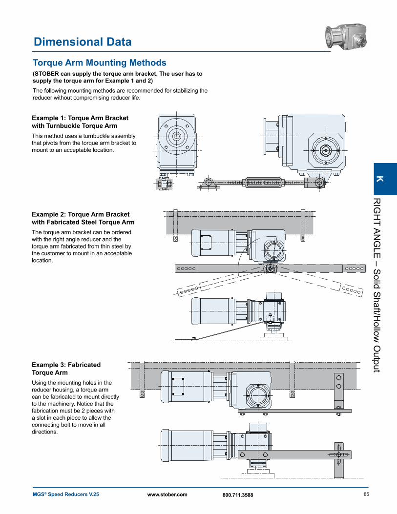
Example 2: Torque Arm Bracket with Fabricated Steel Torque ArmThe torque arm bracket can be ordered with the right angle reducer and the torque arm fabricated from thin steel by the customer to mount in an acceptable location.
Example 3: Fabricated Torque ArmUsing the mounting holes in the reducer housing, a torque arm can be fabricated to mount directly to the machinery. Notice that the fabrication must be 2 pieces with a slot in each piece to allow the connecting bolt to move in all directions.
Example 1: Torque Arm Bracket with Turnbuckle Torque ArmThis method uses a turnbuckle assembly that pivots from the torque arm bracket to mount to an acceptable location.
Torque Arm Mounting Methods (STOBER can supply the torque arm bracket. The user has to supply the torque arm for Example 1 and 2)The following mounting methods are recommended for stabilizing the reducer without compromising reducer life.
MGS® Speed Reducers V.2586 www.stober.com 800.711.3588
MGS®
Speed Reducers K Series: RIGHT ANGLE – Solid Shaft/Hollow Output
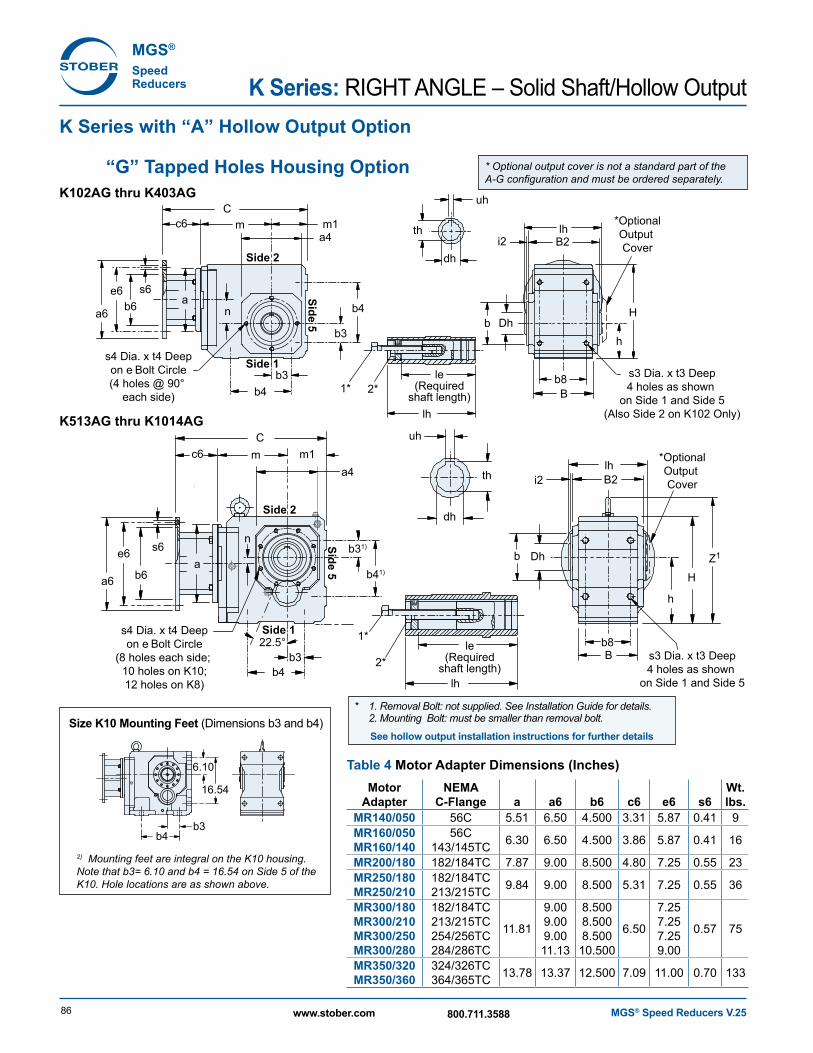
K Series with “A” Hollow Output Option
“G” Tapped Holes Housing OptionK102AG thru K403AG
K513AG thru K1014AG
Cm
a
m1a4
b3
b3
b4
n
n b4
1* 2*
lh
b8le(Required
shaft length)
s3 Dia. x t3 Deep4 holes as shown
on Side 1 and Side 5(Also Side 2 on K102 Only)
s4 Dia. x t4 Deepon e Bolt Circle(4 holes @ 90°
each side)
th
uh
Dh
dh
H
h
B2i2lh
Side 1
Side 2
Side 5
Cm
a
m1a4
b3
b31)
b4
b41)
1*
2*
lh
b8B
B
le(Required
shaft length)s3 Dia. x t3 Deep4 holes as shown
on Side 1 and Side 5
th
uh
Dh
dh
H
h
Z1
i2lhB2
Side 1
Side 2
Side 5
22.5°
b
b
*OptionalOutput Cover
*OptionalOutput Cover
c6
s6b6
e6
a6
c6
s6
b6
e6
a6
s4 Dia. x t4 Deepon e Bolt Circle
(8 holes each side; 10 holes on K10;12 holes on K8)
* 1. Removal Bolt: not supplied. See Installation Guide for details. 2. Mounting Bolt: must be smaller than removal bolt.
See hollow output installation instructions for further details
2) Mounting feet are integral on the K10 housing. Note that b3= 6.10 and b4 = 16.54 on Side 5 of the K10. Hole locations are as shown above.
Size K10 Mounting Feet (Dimensions b3 and b4)
b4b3
6.10
16.54
* Optional output cover is not a standard part of the A-G configuration and must be ordered separately.
Table 4 Motor Adapter Dimensions (Inches)Motor
AdapterNEMA
C-Flange a a6 b6 c6 e6 s6Wt. lbs.
MR14 0/050 56C 5.51 6.50 4.500 3.31 5.87 0.41 9MR160/050MR160/140
56C143/145TC 6.30 6.50 4.500 3.86 5.87 0.41 16
MR200/180 182/184TC 7.87 9.00 8.500 4.80 7.25 0.55 23MR250/180MR250/210
182/184TC213/215TC 9.84 9.00 8.500 5.31 7.25 0.55 36
MR300/180MR300/210MR300/250MR300/280
182/184TC213/215TC254/256TC284/286TC
11.81
9.009.009.0011.13
8.5008.5008.500
10.500
6.50
7.257.257.259.00
0.57 75
MR350/320MR350/360
324/326TC364/365TC 13.78 13.37 12.500 7.09 11.00 0.70 133
MGS® Speed Reducers V.25 87www.stober.com 800.711.3588
KR
IGH
T AN
GLE
– Solid S
haft/Hollow
Output
Dimensional Data
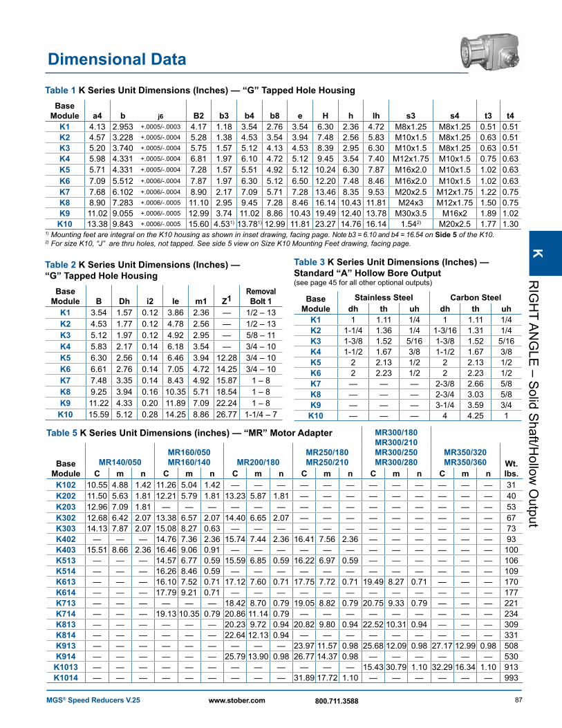
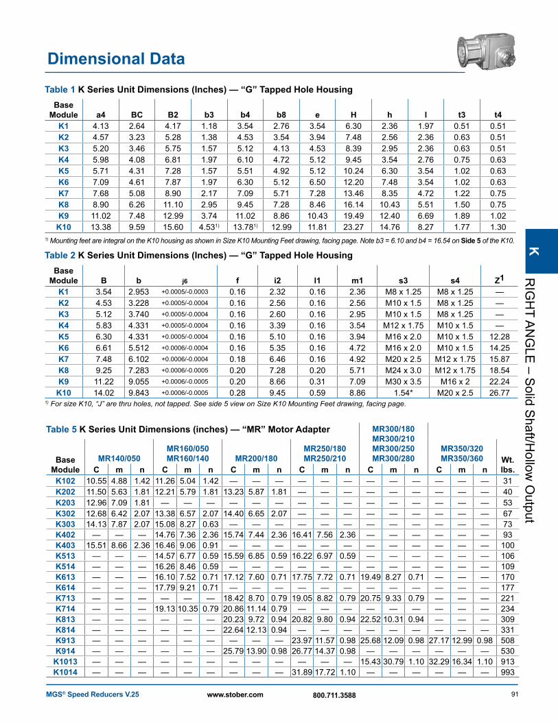
Table 2 K Series Unit Dimensions (Inches) — “G” Tapped Hole Housing
Base Module B Dh i2 le m1 Z1
Removal Bolt 1
K1 3.54 1.57 0.12 3.86 2.36 — 1/2 – 13K2 4.53 1.77 0.12 4.78 2.56 — 1/2 – 13K3 5.12 1.97 0.12 4.92 2.95 — 5/8 – 11K4 5.83 2.17 0.14 6.18 3.54 — 3/4 – 10K5 6.30 2.56 0.14 6.46 3.94 12.28 3/4 – 10K6 6.61 2.76 0.14 7.05 4.72 14.25 3/4 – 10K7 7.48 3.35 0.14 8.43 4.92 15.87 1 – 8K8 9.25 3.94 0.16 10.35 5.71 18.54 1 – 8K9 11.22 4.33 0.20 11.89 7.09 22.24 1 – 8
K10 15.59 5.12 0.28 14.25 8.86 26.77 1-1/4 – 7
Table 1 K Series Unit Dimensions (Inches) — “G” Tapped Hole HousingBase
Module a4 b j6 B2 b3 b4 b8 e H h lh s3 s4 t3 t4K1 4.13 2.953 +.0005/-.0003 4.17 1.18 3.54 2.76 3.54 6.30 2.36 4.72 M8x1.25 M8x1.25 0.51 0.51K2 4.57 3.228 +.0005/-.0004 5.28 1.38 4.53 3.54 3.94 7.48 2.56 5.83 M10x1.5 M8x1.25 0.63 0.51K3 5.20 3.740 +.0005/-.0004 5.75 1.57 5.12 4.13 4.53 8.39 2.95 6.30 M10x1.5 M8x1.25 0.63 0.51K4 5.98 4.331 +.0005/-.0004 6.81 1.97 6.10 4.72 5.12 9.45 3.54 7.40 M12x1.75 M10x1.5 0.75 0.63K5 5.71 4.331 +.0005/-.0004 7.28 1.57 5.51 4.92 5.12 10.24 6.30 7.87 M16x2.0 M10x1.5 1.02 0.63K6 7.09 5.512 +.0006/-.0004 7.87 1.97 6.30 5.12 6.50 12.20 7.48 8.46 M16x2.0 M10x1.5 1.02 0.63K7 7.68 6.102 +.0006/-.0004 8.90 2.17 7.09 5.71 7.28 13.46 8.35 9.53 M20x2.5 M12x1.75 1.22 0.75K8 8.90 7.283 +.0006/-.0005 11.10 2.95 9.45 7.28 8.46 16.14 10.43 11.81 M24x3 M12x1.75 1.50 0.75K9 11.02 9.055 +.0006/-.0005 12.99 3.74 11.02 8.86 10.43 19.49 12.40 13.78 M30x3.5 M16x2 1.89 1.02K10 13.38 9.843 +.0006/-.0005 15.60 4.531) 13.781) 12.99 11.81 23.27 14.76 16.14 1.542) M20x2.5 1.77 1.30
1) Mounting feet are integral on the K10 housing as shown in inset drawing, facing page. Note b3 = 6.10 and b4 = 16.54 on Side 5 of the K10. 2) For size K10, “J” are thru holes, not tapped. See side 5 view on Size K10 Mounting Feet drawing, facing page.
Table 3 K Series Unit Dimensions (Inches) — Standard “A” Hollow Bore Output (see page 45 for all other optional outputs)
Base Module
Stainless Steel Carbon Steeldh th uh dh th uh
K1 1 1.11 1/4 1 1.11 1/4K2 1-1/4 1.36 1/4 1-3/16 1.31 1/4K3 1-3/8 1.52 5/16 1-3/8 1.52 5/16K4 1-1/2 1.67 3/8 1-1/2 1.67 3/8K5 2 2.13 1/2 2 2.13 1/2K6 2 2.23 1/2 2 2.23 1/2K7 — — — 2-3/8 2.66 5/8K8 — — — 2-3/4 3.03 5/8K9 — — — 3-1/4 3.59 3/4
K10 — — — 4 4.25 1
Table 5 K Series Unit Dimensions (inches) — “MR” Motor Adapter MR300/180 MR300/210 MR300/250 MR300/280
MR350/320 MR350/360Base
ModuleMR140/050
MR160/050 MR160/140 MR200/180
MR250/180 MR250/210 Wt.
lbs.C m n C m n C m n C m n C m n C m nK102 10.55 4.88 1.42 11.26 5.04 1.42 — — — — — — — — — — — — 31K202 11.50 5.63 1.81 12.21 5.79 1.81 13.23 5.87 1.81 — — — — — — — — — 40K203 12.96 7.09 1.81 — — — — — — — — — — — — — — — 53K302 12.68 6.42 2.07 13.38 6.57 2.07 14.40 6.65 2.07 — — — — — — — — — 67K303 14.13 7.87 2.07 15.08 8.27 0.63 — — — — — — — — — — — — 73K402 — — — 14.76 7.36 2.36 15.74 7.44 2.36 16.41 7.56 2.36 — — — — — — 93K403 15.51 8.66 2.36 16.46 9.06 0.91 — — — — — — — — — — — — 100K513 — — — 14.57 6.77 0.59 15.59 6.85 0.59 16.22 6.97 0.59 — — — — — — 106K514 — — — 16.26 8.46 0.59 — — — — — — — — — — — — 109K613 — — — 16.10 7.52 0.71 17.12 7.60 0.71 17.75 7.72 0.71 19.49 8.27 0.71 — — — 170K614 — — — 17.79 9.21 0.71 — — — — — — — — — — — — 177K713 — — — — — — 18.42 8.70 0.79 19.05 8.82 0.79 20.75 9.33 0.79 — — — 221K714 — — — 19.13 10.35 0.79 20.86 11.14 0.79 — — — — — — — — — 234K813 — — — — — — 20.23 9.72 0.94 20.82 9.80 0.94 22.52 10.31 0.94 — — — 309K814 — — — — — — 22.64 12.13 0.94 — — — — — — — — — 331K913 — — — — — — — — — 23.97 11.57 0.98 25.68 12.09 0.98 27.17 12.99 0.98 508K914 — — — — — — 25.79 13.90 0.98 26.77 14.37 0.98 — — — — — — 530K1013 — — — — — — — — — — — — 15.43 30.79 1.10 32.29 16.34 1.10 913K1014 — — — — — — — — — 31.89 17.72 1.10 — — — — — — 993
MGS® Speed Reducers V.2588 www.stober.com 800.711.3588
MGS®
Speed Reducers K Series: RIGHT ANGLE – Solid Shaft/Hollow Output
Cm m1
Cm
na
m1
f1c1
f1c1
b1
a1
s1 Dia.on e1 Bolt Circle
s1 Dia.on e1 Bolt Circle
th
th
uh
uh
dh
dh
B
lh
lh
le(Required
shaft length)
le(Required
shaft length)lh
1*2*
1* 2*
Z1H
h
Dh
B2
b1
a1
B
lh
H
h
Dh
B2i2
i2
an
c6
s6b6
e6
a6
c6s6
b6
e6
a6
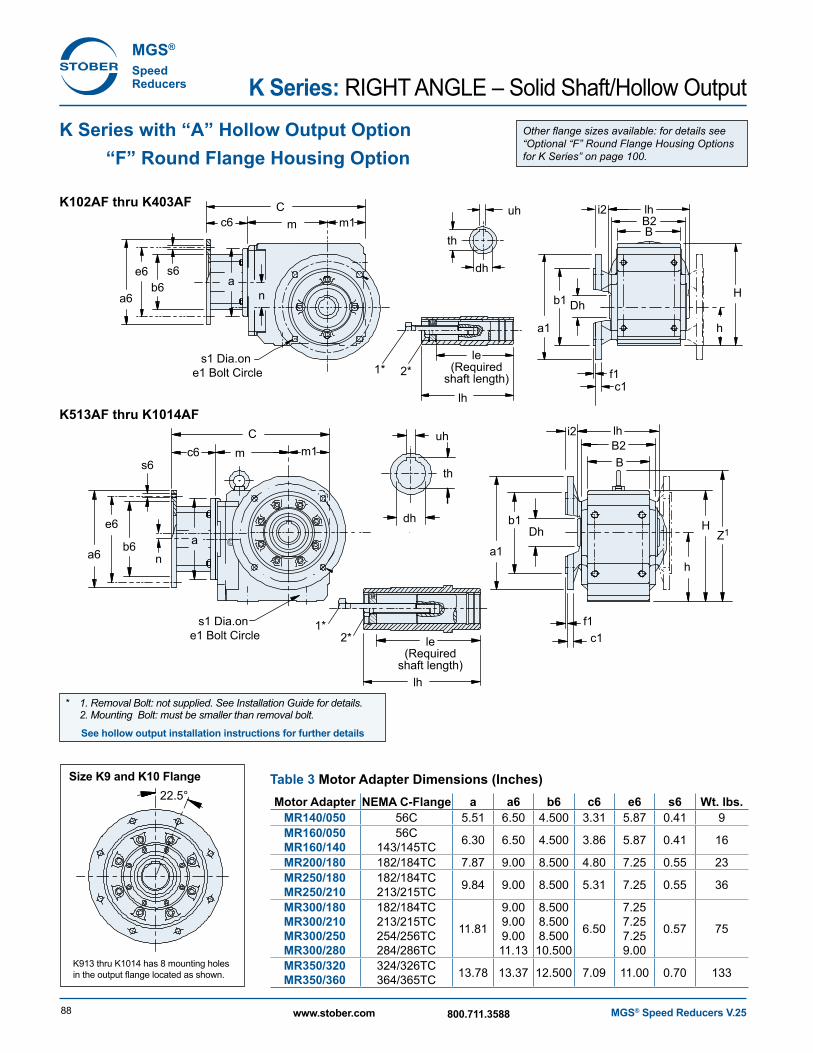
K102AF thru K403AF
K513AF thru K1014AF
Other flange sizes available: for details see “Optional “F” Round Flange Housing Options for K Series” on page 100.
Table 3 Motor Adapter Dimensions (Inches)Motor Adapter NEMA C-Flange a a6 b6 c6 e6 s6 Wt. lbs.
MR14 0/050 56C 5.51 6.50 4.500 3.31 5.87 0.41 9MR160/050MR160/140
56C143/145TC 6.30 6.50 4.500 3.86 5.87 0.41 16
MR200/180 182/184TC 7.87 9.00 8.500 4.80 7.25 0.55 23MR250/180MR250/210
182/184TC213/215TC 9.84 9.00 8.500 5.31 7.25 0.55 36
MR300/180MR300/210MR300/250MR300/280
182/184TC213/215TC254/256TC284/286TC
11.81
9.009.009.0011.13
8.5008.5008.500
10.500
6.50
7.257.257.259.00
0.57 75
MR350/320MR350/360
324/326TC364/365TC 13.78 13.37 12.500 7.09 11.00 0.70 133
K913 thru K1014 has 8 mounting holes in the output flange located as shown.
22.5°Size K9 and K10 Flange
* 1. Removal Bolt: not supplied. See Installation Guide for details. 2. Mounting Bolt: must be smaller than removal bolt.
See hollow output installation instructions for further details
K Series with “A” Hollow Output Option “F” Round Flange Housing Option
MGS® Speed Reducers V.25 89www.stober.com 800.711.3588
KR
IGH
T AN
GLE
– Solid S
haft/Hollow
Output
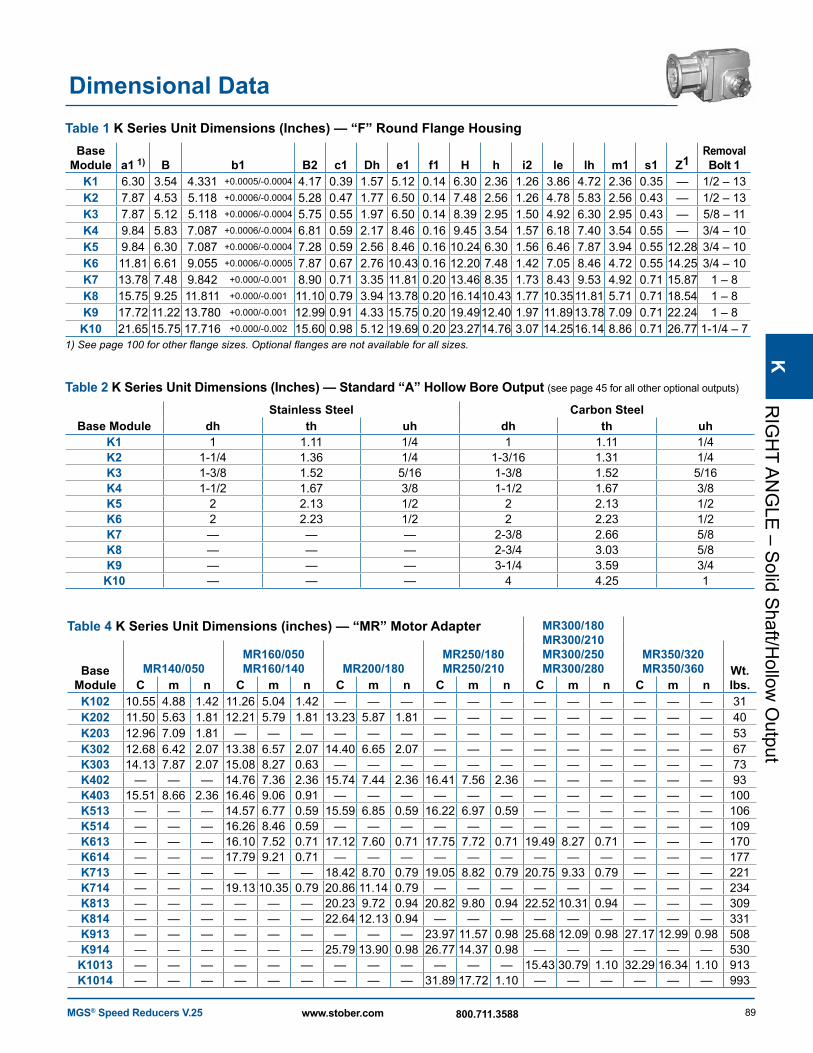
Dimensional DataTable 1 K Series Unit Dimensions (Inches) — “F” Round Flange Housing
Base Module a1 1) B b1 B2 c1 Dh e1 f1 H h i2 le lh m1 s1 Z1
Removal Bolt 1
K1 6.30 3.54 4.331 +0.0005/-0.0004 4.17 0.39 1.57 5.12 0.14 6.30 2.36 1.26 3.86 4.72 2.36 0.35 — 1/2 – 13K2 7.87 4.53 5.118 +0.0006/-0.0004 5.28 0.47 1.77 6.50 0.14 7.48 2.56 1.26 4.78 5.83 2.56 0.43 — 1/2 – 13K3 7.87 5.12 5.118 +0.0006/-0.0004 5.75 0.55 1.97 6.50 0.14 8.39 2.95 1.50 4.92 6.30 2.95 0.43 — 5/8 – 11K4 9.84 5.83 7.087 +0.0006/-0.0004 6.81 0.59 2.17 8.46 0.16 9.45 3.54 1.57 6.18 7.40 3.54 0.55 — 3/4 – 10K5 9.84 6.30 7.087 +0.0006/-0.0004 7.28 0.59 2.56 8.46 0.16 10.24 6.30 1.56 6.46 7.87 3.94 0.55 12.28 3/4 – 10K6 11.81 6.61 9.055 +0.0006/-0.0005 7.87 0.67 2.76 10.43 0.16 12.20 7.48 1.42 7.05 8.46 4.72 0.55 14.25 3/4 – 10K7 13.78 7.48 9.842 +0.000/-0.001 8.90 0.71 3.35 11.81 0.20 13.46 8.35 1.73 8.43 9.53 4.92 0.71 15.87 1 – 8K8 15.75 9.25 11.811 +0.000/-0.001 11.10 0.79 3.94 13.78 0.20 16.1410.43 1.77 10.3511.81 5.71 0.71 18.54 1 – 8K9 17.72 11.22 13.780 +0.000/-0.001 12.99 0.91 4.33 15.75 0.20 19.4912.40 1.97 11.8913.78 7.09 0.71 22.24 1 – 8
K10 21.65 15.75 17.716 +0.000/-0.002 15.60 0.98 5.12 19.69 0.20 23.2714.76 3.07 14.2516.14 8.86 0.71 26.77 1-1/4 – 71) See page 100 for other flange sizes. Optional flanges are not available for all sizes.
Table 2 K Series Unit Dimensions (Inches) — Standard “A” Hollow Bore Output (see page 45 for all other optional outputs)
Base ModuleStainless Steel Carbon Steel
dh th uh dh th uhK1 1 1.11 1/4 1 1.11 1/4K2 1-1/4 1.36 1/4 1-3/16 1.31 1/4K3 1-3/8 1.52 5/16 1-3/8 1.52 5/16K4 1-1/2 1.67 3/8 1-1/2 1.67 3/8K5 2 2.13 1/2 2 2.13 1/2K6 2 2.23 1/2 2 2.23 1/2K7 — — — 2-3/8 2.66 5/8K8 — — — 2-3/4 3.03 5/8K9 — — — 3-1/4 3.59 3/4K10 — — — 4 4.25 1
Table 4 K Series Unit Dimensions (inches) — “MR” Motor Adapter MR300/180 MR300/210 MR300/250 MR300/280
MR350/320 MR350/360Base
ModuleMR140/050
MR160/050 MR160/140 MR200/180
MR250/180 MR250/210 Wt.
lbs.C m n C m n C m n C m n C m n C m nK102 10.55 4.88 1.42 11.26 5.04 1.42 — — — — — — — — — — — — 31K202 11.50 5.63 1.81 12.21 5.79 1.81 13.23 5.87 1.81 — — — — — — — — — 40K203 12.96 7.09 1.81 — — — — — — — — — — — — — — — 53K302 12.68 6.42 2.07 13.38 6.57 2.07 14.40 6.65 2.07 — — — — — — — — — 67K303 14.13 7.87 2.07 15.08 8.27 0.63 — — — — — — — — — — — — 73K402 — — — 14.76 7.36 2.36 15.74 7.44 2.36 16.41 7.56 2.36 — — — — — — 93K403 15.51 8.66 2.36 16.46 9.06 0.91 — — — — — — — — — — — — 100K513 — — — 14.57 6.77 0.59 15.59 6.85 0.59 16.22 6.97 0.59 — — — — — — 106K514 — — — 16.26 8.46 0.59 — — — — — — — — — — — — 109K613 — — — 16.10 7.52 0.71 17.12 7.60 0.71 17.75 7.72 0.71 19.49 8.27 0.71 — — — 170K614 — — — 17.79 9.21 0.71 — — — — — — — — — — — — 177K713 — — — — — — 18.42 8.70 0.79 19.05 8.82 0.79 20.75 9.33 0.79 — — — 221K714 — — — 19.13 10.35 0.79 20.86 11.14 0.79 — — — — — — — — — 234K813 — — — — — — 20.23 9.72 0.94 20.82 9.80 0.94 22.52 10.31 0.94 — — — 309K814 — — — — — — 22.64 12.13 0.94 — — — — — — — — — 331K913 — — — — — — — — — 23.97 11.57 0.98 25.68 12.09 0.98 27.17 12.99 0.98 508K914 — — — — — — 25.79 13.90 0.98 26.77 14.37 0.98 — — — — — — 530K1013 — — — — — — — — — — — — 15.43 30.79 1.10 32.29 16.34 1.10 913K1014 — — — — — — — — — 31.89 17.72 1.10 — — — — — — 993
MGS® Speed Reducers V.2590 www.stober.com 800.711.3588
MGS®
Speed Reducers K Series: RIGHT ANGLE – Solid Shaft/Hollow Output
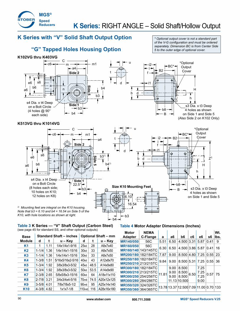
K Series with “V” Solid Shaft Output Option
“G” Tapped Holes Housing OptionK102VG thru K403VG
K513VG thru K1014VG
Cm
a
m1a4
b3
b3
b4
n
n b4
b8s3 Dia. x t3 Deep4 holes as shown
on Side 1 and Side 5(Also Side 2 on K102 Only)
s4 Dia. x t4 Deepon e Bolt Circle(4 holes @ 90°
each side)
H
*OptionalOutput Cover
*OptionalOutput Cover
h
f
f
B2BC*
Side 1
Side 2
Side 5
Cm
a
m1a4
b3
b31)
b4
b41)
b8B
B
s3 Dia. x t3 Deep4 holes as shown
on Side 1 and Side 5
s4 Dia. x t4 Deepon e Bolt Circle
(8 holes each side; 10 holes on K10;12 holes on K8)
H
h
Z1
B2
Side 1
Side 2Side 5
22.5°
b
b
t
u
d
d
i2l
l1
t
u
d
d
li2
BC*
l1
c6
s6b6
e6
a6
c6
s6
b6
e6
a6
2) Mounting feet are integral on the K10 housing. Note that b3 = 6.10 and b4 = 16.54 on Side 5 of the K10, with hole locations as shown at right.
Table 3 K Series — “V” Shaft Output (Carbon Steel) (see page 45 for standard SS, and other optional outputs)
Base Module
Standard Shaft – inches Optional Shaft – mmd t u – Key d t u – Key
K1 1 1.11 1/4x1/4x1-9/16 25k6 28 A8x7x40K2 1-1/4 1.36 1/4x1/4x1-15/16 30k6 33 A8x7x50K3 1-1/4 1.36 1/4x1/4x1-15/16 30k6 33 A8x7x50K4 1-3/8 1.51 5/16x5/16x2-5/16 40k6 43 A12x8x70K5 1-3/4 1.92 3/8x3/8x3-5/32 45k6 48.5 A14x9x80K6 1-3/4 1.92 3/8x3/8x3-5/32 50k6 53.5 A14x9x90K7 2-3/8 2.65 5/8x5/8x3-15/16 60k6 64 A18x11x110K8 2-7/8 3.21 3/4x3/4x4-5/16 70m6 74.5 A20x12x125K9 3-5/8 4.01 7/8x7/8x5-1/2 90m6 95 A25x14x140
K10 4-3/8 4.82 1x1x7-1/8 110m6 116 A28x16x180
* Optional output cover is not a standard part of the V-G configuration and must be ordered separately. Dimension BC is from Center Side 5 to the outer edge of optional cover.
b4b3
6.10
16.54
Size K10 Mounting Feet
Table 4 Motor Adapter Dimensions (Inches)Motor
AdapterNEMA
C-Flange a a6 b6 c6 e6 s6Wt. lbs.
MR14 0/050 56C 5.51 6.50 4.500 3.31 5.87 0.41 9MR160/050MR160/140
56C143/145TC 6.30 6.50 4.500 3.86 5.87 0.41 16
MR200/180 182/184TC 7.87 9.00 8.500 4.80 7.25 0.55 23MR250/180MR250/210
182/184TC213/215TC 9.84 9.00 8.500 5.31 7.25 0.55 36
MR300/180MR300/210MR300/250MR300/280
182/184TC213/215TC254/256TC284/286TC
11.81
9.009.009.0011.13
8.5008.5008.50010.500
6.50
7.257.257.259.00
0.57 75
MR350/320MR350/360
324/326TC364/365TC 13.78 13.37 12.500 7.09 11.00 0.70 133
MGS® Speed Reducers V.25 91www.stober.com 800.711.3588
KR
IGH
T AN
GLE
– Solid S
haft/Hollow
Output
Dimensional Data
Table 2 K Series Unit Dimensions (Inches) — “G” Tapped Hole HousingBase
Module B b j6 f i2 l1 m1 s3 s4 Z1K1 3.54 2.953 +0.0005/-0.0003 0.16 2.32 0.16 2.36 M8 x 1.25 M8 x 1.25 —K2 4.53 3.228 +0.0005/-0.0004 0.16 2.56 0.16 2.56 M10 x 1.5 M8 x 1.25 —K3 5.12 3.740 +0.0005/-0.0004 0.16 2.60 0.16 2.95 M10 x 1.5 M8 x 1.25 —K4 5.83 4.331 +0.0005/-0.0004 0.16 3.39 0.16 3.54 M12 x 1.75 M10 x 1.5 —K5 6.30 4.331 +0.0005/-0.0004 0.16 5.10 0.16 3.94 M16 x 2.0 M10 x 1.5 12.28K6 6.61 5.512 +0.0006/-0.0004 0.16 5.35 0.16 4.72 M16 x 2.0 M10 x 1.5 14.25K7 7.48 6.102 +0.0006/-0.0004 0.18 6.46 0.16 4.92 M20 x 2.5 M12 x 1.75 15.87K8 9.25 7.283 +0.0006/-0.0005 0.20 7.28 0.20 5.71 M24 x 3.0 M12 x 1.75 18.54K9 11.22 9.055 +0.0006/-0.0005 0.20 8.66 0.31 7.09 M30 x 3.5 M16 x 2 22.24K10 14.02 9.843 +0.0006/-0.0005 0.28 9.45 0.59 8.86 1.54* M20 x 2.5 26.77
1) For size K10, “J” are thru holes, not tapped. See side 5 view on Size K10 Mounting Feet drawing, facing page.
Table 1 K Series Unit Dimensions (Inches) — “G” Tapped Hole HousingBase
Module a4 BC B2 b3 b4 b8 e H h l t3 t4K1 4.13 2.64 4.17 1.18 3.54 2.76 3.54 6.30 2.36 1.97 0.51 0.51K2 4.57 3.23 5.28 1.38 4.53 3.54 3.94 7.48 2.56 2.36 0.63 0.51K3 5.20 3.46 5.75 1.57 5.12 4.13 4.53 8.39 2.95 2.36 0.63 0.51K4 5.98 4.08 6.81 1.97 6.10 4.72 5.12 9.45 3.54 2.76 0.75 0.63K5 5.71 4.31 7.28 1.57 5.51 4.92 5.12 10.24 6.30 3.54 1.02 0.63K6 7.09 4.61 7.87 1.97 6.30 5.12 6.50 12.20 7.48 3.54 1.02 0.63K7 7.68 5.08 8.90 2.17 7.09 5.71 7.28 13.46 8.35 4.72 1.22 0.75K8 8.90 6.26 11.10 2.95 9.45 7.28 8.46 16.14 10.43 5.51 1.50 0.75K9 11.02 7.48 12.99 3.74 11.02 8.86 10.43 19.49 12.40 6.69 1.89 1.02
K10 13.38 9.59 15.60 4.531) 13.781) 12.99 11.81 23.27 14.76 8.27 1.77 1.301) Mounting feet are integral on the K10 housing as shown in Size K10 Mounting Feet drawing, facing page. Note b3 = 6.10 and b4 = 16.54 on Side 5 of the K10.
Table 5 K Series Unit Dimensions (inches) — “MR” Motor Adapter MR300/180 MR300/210 MR300/250 MR300/280
MR350/320 MR350/360Base
ModuleMR140/050
MR160/050 MR160/140 MR200/180
MR250/180 MR250/210 Wt.
lbs.C m n C m n C m n C m n C m n C m nK102 10.55 4.88 1.42 11.26 5.04 1.42 — — — — — — — — — — — — 31K202 11.50 5.63 1.81 12.21 5.79 1.81 13.23 5.87 1.81 — — — — — — — — — 40K203 12.96 7.09 1.81 — — — — — — — — — — — — — — — 53K302 12.68 6.42 2.07 13.38 6.57 2.07 14.40 6.65 2.07 — — — — — — — — — 67K303 14.13 7.87 2.07 15.08 8.27 0.63 — — — — — — — — — — — — 73K402 — — — 14.76 7.36 2.36 15.74 7.44 2.36 16.41 7.56 2.36 — — — — — — 93K403 15.51 8.66 2.36 16.46 9.06 0.91 — — — — — — — — — — — — 100K513 — — — 14.57 6.77 0.59 15.59 6.85 0.59 16.22 6.97 0.59 — — — — — — 106K514 — — — 16.26 8.46 0.59 — — — — — — — — — — — — 109K613 — — — 16.10 7.52 0.71 17.12 7.60 0.71 17.75 7.72 0.71 19.49 8.27 0.71 — — — 170K614 — — — 17.79 9.21 0.71 — — — — — — — — — — — — 177K713 — — — — — — 18.42 8.70 0.79 19.05 8.82 0.79 20.75 9.33 0.79 — — — 221K714 — — — 19.13 10.35 0.79 20.86 11.14 0.79 — — — — — — — — — 234K813 — — — — — — 20.23 9.72 0.94 20.82 9.80 0.94 22.52 10.31 0.94 — — — 309K814 — — — — — — 22.64 12.13 0.94 — — — — — — — — — 331K913 — — — — — — — — — 23.97 11.57 0.98 25.68 12.09 0.98 27.17 12.99 0.98 508K914 — — — — — — 25.79 13.90 0.98 26.77 14.37 0.98 — — — — — — 530K1013 — — — — — — — — — — — — 15.43 30.79 1.10 32.29 16.34 1.10 913K1014 — — — — — — — — — 31.89 17.72 1.10 — — — — — — 993
MGS® Speed Reducers V.2692 www.stober.com 800.711.3588
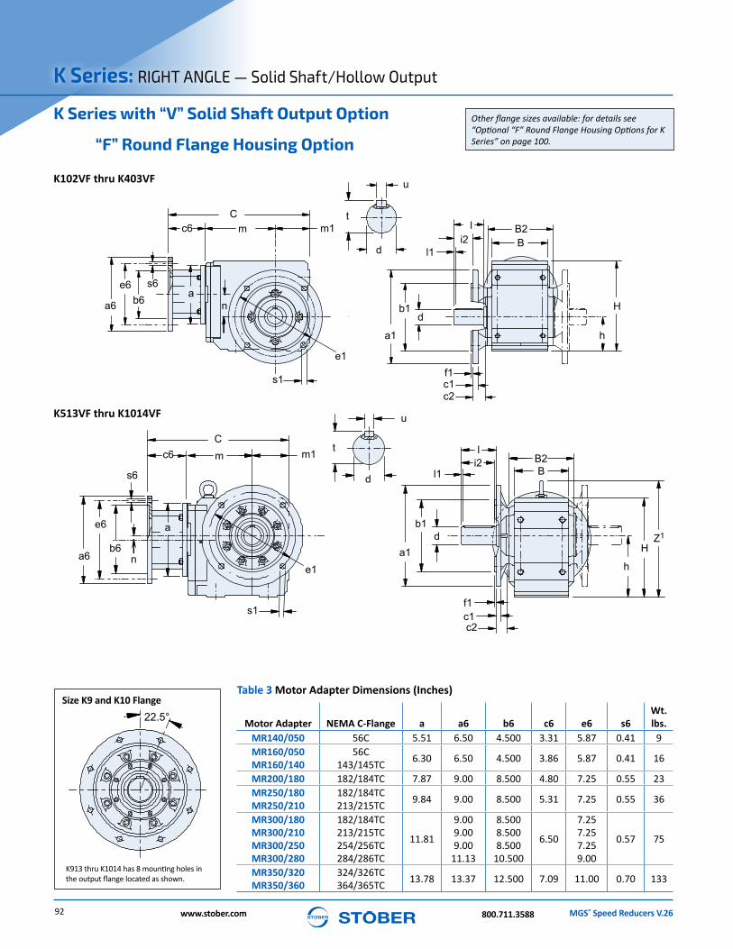
K Series: RIGHT ANGLE — Solid Shaft/Hollow Output
K913 thru K1014 has 8 mounting holes in the output flange located as shown.
K Series with “V” Solid Shaft Output Option
“F” Round Flange Housing Option
K102VF thru K403VF
K513VF thru K1014VF
Other flange sizes available: for details see “Optional “F” Round Flange Housing Options for K Series” on page 100.
Cm
a
m1
m1
n
f1c1c2
c2
b1
a1
s1
t
u
d
d
l
BB2
B2
i2l1
H
H
h
h
Z1
C
n
m
f1c1
b1
a1e1
e1
s1
t
u
d
dB
li2
l1
a
c6
s6b6
e6
a6
c6
s6
b6
e6
a6
22.5°Size K9 and K10 Flange
Table 3 Motor Adapter Dimensions (Inches)
Motor Adapter NEMA C-Flange a a6 b6 c6 e6 s6Wt. lbs.
MR14 0/050 56C 5.51 6.50 4.500 3.31 5.87 0.41 9MR160/050MR160/140
56C143/145TC 6.30 6.50 4.500 3.86 5.87 0.41 16
MR200/180 182/184TC 7.87 9.00 8.500 4.80 7.25 0.55 23MR250/180MR250/210
182/184TC213/215TC 9.84 9.00 8.500 5.31 7.25 0.55 36
MR300/180MR300/210MR300/250MR300/280
182/184TC213/215TC254/256TC284/286TC
11.81
9.009.009.00
11.13
8.5008.5008.500
10.500
6.50
7.257.257.259.00
0.57 75
MR350/320MR350/360
324/326TC364/365TC 13.78 13.37 12.500 7.09 11.00 0.70 133

MGS® Speed Reducers V.26 93www.stober.com800.711.3588
RIG
HT A
NG
LE — Solid Shaft/H
ollow O
utputKTable 2 K Series Unit Dimensions — “V” Shaft Output (Carbon Steel)
(see page 45 for standard SS, and other optional outputs)
Base Module
Standard Shaft – inches Optional Shaft – mmd t u – Key d t u – Key
K1 1 1.11 1/4 x 1/4 x 1-9/16 25k6 28 A8 x 7 x 40K2 1-1/4 1.36 1/4 x 1/4 x 1-15/16 30k6 33 A8 x 7 x 50K3 1-1/4 1.36 1/4 x 1/4 x 1-15/16 30k6 33 A8 x 7 x 50K4 1-3/8 1.51 5/16 x 5/16 x 2-5/16 40k6 43 A12 x 8 x 70K5 1-3/4 1.92 3/8 x 3/8 x 3-5/32 45k6 48.5 A14 x 9 x 80K6 1-3/4 1.92 3/8 x 3/8 x 3-5/32 50k6 53.5 A14 x 9 x 90K7 2-3/8 2.65 5/8 x 5/8 x 3-15/16 60k6 64 A18 x 11 x 110K8 2-7/8 3.21 3/4 x 3/4 x 4-5/16 70m6 74.5 A20 x 12 x 125K9 3-5/8 4.01 7/8 x 7/8 x 5-1/2 90m6 95 A25 x 14 x 140
K10 4-3/8 4.82 1 x 1 x 7-1/8 110m6 116 A28 x 16 x 180
Table 1 K Series Unit Dimensions (Inches) — “F” Round Flange Housing
Base Module a1
1)B b1 B2 c1 c2 e1 f1 H h i2 l l1 m1 s1 Z1
K1 6.30 3.54 4.331 +0.0005/-0.0004 4.17 0.39 1.26 5.12 0.14 6.30 2.36 1.18 1.97 0.16 2.36 0.35 —K2 7.87 4.53 5.118 +0.0006/-0.0004 5.28 0.47 1.26 6.50 0.14 7.48 2.56 1.42 2.36 0.16 2.56 0.43 —K3 7.87 5.12 5.118 +0.0006/-0.0004 5.75 0.55 1.50 6.50 0.14 8.39 2.95 1.22 2.36 0.16 2.95 0.43 —K4 9.84 5.83 7.087 +0.0006/-0.0005 6.81 0.59 1.57 8.46 0.16 9.45 3.54 1.95 3.14 0.16 3.54 0.55 —K5 9.84 6.30 7.087 +0.0006/-0.0005 7.28 0.59 1.56 8.46 0.16 10.24 6.30 3.54 3.54 0.16 3.54 0.55 12.28K6 11.81 6.61 9.055 +0.0006/-0.0005 7.87 0.67 1.42 10.43 0.16 12.20 7.48 3.94 3.94 0.16 4.72 0.55 14.25K7 13.78 7.48 9.842 +0.000/-0.001 8.90 0.71 1.73 11.81 0.20 13.46 8.35 4.72 4.72 0.16 4.92 0.71 15.87K8 15.75 9.25 11.811 +0.000/-0.001 11.10 0.79 1.77 13.78 0.20 16.14 10.43 5.51 5.51 0.20 5.71 0.71 18.54K9 17.72 11.22 13.780 +0.000/-0.001 12.99 0.91 1.97 15.75 0.20 19.49 12.40 6.69 6.69 0.31 7.09 0.71 22.24
K10 21.65 15.75 17.716 +0.000/-0.002 14.02 0.98 3.07 19.69 0.20 23.27 14.76 8.27 8.27 0.59 8.86 0.71 26.771) See page 100 for other flange sizes. Optional flanges are not available for all sizes.
Table 4 K Series Unit Dimensions (inches) — “MR” Motor Adapter MR300/180 MR300/210 MR300/250 MR300/280
MR350/320 MR350/360Base
ModuleMR140/050
MR160/050 MR160/140 MR200/180
MR250/180 MR250/210 Wt.
lbs.C m n C m n C m n C m n C m n C m nK102 10.55 4.88 1.42 11.26 5.04 1.42 — — — — — — — — — — — — 31K202 11.50 5.63 1.81 12.21 5.79 1.81 13.23 5.87 1.81 — — — — — — — — — 40K203 12.96 7.09 1.81 — — — — — — — — — — — — — — — 53K302 12.68 6.42 2.07 13.38 6.57 2.07 14.40 6.65 2.07 — — — — — — — — — 67K303 14.13 7.87 2.07 15.08 8.27 0.63 — — — — — — — — — — — — 73K402 — — — 14.76 7.36 2.36 15.74 7.44 2.36 16.41 7.56 2.36 — — — — — — 93K403 15.51 8.66 2.36 16.46 9.06 0.91 — — — — — — — — — — — — 100K513 — — — 14.57 6.77 0.59 15.59 6.85 0.59 16.22 6.97 0.59 — — — — — — 106K514 — — — 16.26 8.46 0.59 — — — — — — — — — — — — 109K613 — — — 16.10 7.52 0.71 17.12 7.60 0.71 17.75 7.72 0.71 19.49 8.27 0.71 — — — 170K614 — — — 17.79 9.21 0.71 — — — — — — — — — — — — 177K713 — — — — — — 18.42 8.70 0.79 19.05 8.82 0.79 20.75 9.33 0.79 — — — 221K714 — — — 19.13 10.35 0.79 20.86 11.14 0.79 — — — — — — — — — 234K813 — — — — — — 20.23 9.72 0.94 20.82 9.80 0.94 22.52 10.31 0.94 — — — 309K814 — — — — — — 22.64 12.13 0.94 — — — — — — — — — 331K913 — — — — — — — — — 23.97 11.57 0.98 25.68 12.09 0.98 27.17 12.99 0.98 508K914 — — — — — — 25.79 13.90 0.98 26.77 14.37 0.98 — — — — — — 530
K1013 — — — — — — — — — — — — 15.43 30.79 1.10 32.29 16.34 1.10 913K1014 — — — — — — — — — 31.89 17.72 1.10 — — — — — — 993
Dimensional Data
MGS® Speed Reducers V.2694 www.stober.com 800.711.3588
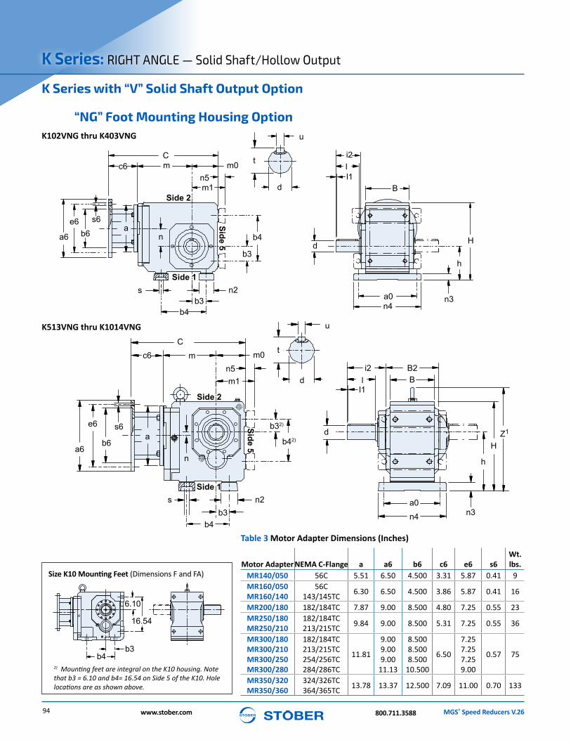
K Series: RIGHT ANGLE — Solid Shaft/Hollow Output
K Series with “V” Solid Shaft Output Option
“NG” Foot Mounting Housing Option
2) Mounting feet are integral on the K10 housing. Note that b3 = 6.10 and b4= 16.54 on Side 5 of the K10. Hole locations are as shown above.
K513VNG thru K1014VNG
K102VNG thru K403VNG
Size K10 Mounting Feet (Dimensions F and FA)
Cm m0
n3b3
b3
b4
b4
s
n4a0
t
u
d
d
i2
B
ll1
H
h
n2
Cm m0
m1n5
m1n5
Z1
b3
b32)
b4
b42)
s
t
u
d
d
i2Bl
l1
H
h
n3n4
a0
B2
n2Side 1
Side 2
Side 5
Side 1
Side 2
Side 5
n
n
a
a
c6
s6
b6e6
a6
c6
s6
b6
e6
a6
b4b3
6.10
16.54
Table 3 Motor Adapter Dimensions (Inches)
Motor Adapter NEMA C-Flange a a6 b6 c6 e6 s6Wt. lbs.
MR14 0/050 56C 5.51 6.50 4.500 3.31 5.87 0.41 9MR160/050MR160/140
56C143/145TC 6.30 6.50 4.500 3.86 5.87 0.41 16
MR200/180 182/184TC 7.87 9.00 8.500 4.80 7.25 0.55 23MR250/180MR250/210
182/184TC213/215TC 9.84 9.00 8.500 5.31 7.25 0.55 36
MR300/180MR300/210MR300/250MR300/280
182/184TC213/215TC254/256TC284/286TC
11.81
9.009.009.00
11.13
8.5008.5008.500
10.500
6.50
7.257.257.259.00
0.57 75
MR350/320MR350/360
324/326TC364/365TC 13.78 13.37 12.500 7.09 11.00 0.70 133
MGS® Speed Reducers V.26 95www.stober.com800.711.3588
RIG
HT A
NG
LE — Solid Shaft/H
ollow O
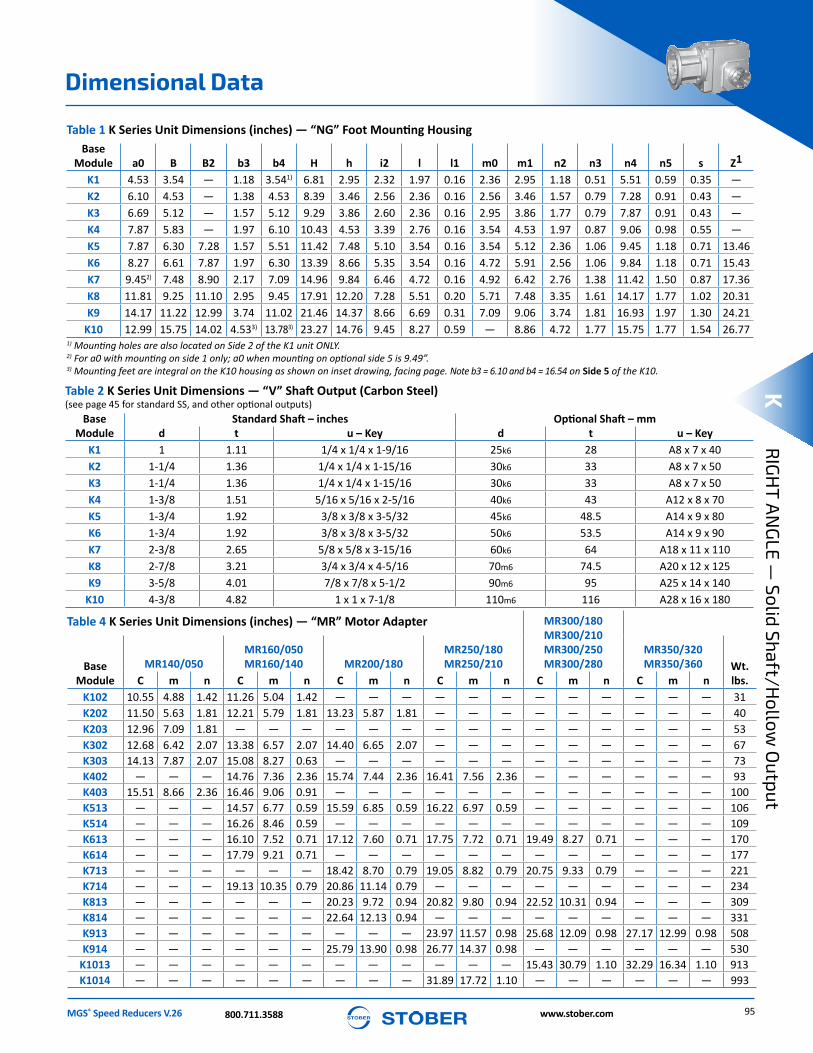
utputKTable 2 K Series Unit Dimensions — “V” Shaft Output (Carbon Steel)
(see page 45 for standard SS, and other optional outputs)Base
ModuleStandard Shaft – inches Optional Shaft – mm
d t u – Key d t u – KeyK1 1 1.11 1/4 x 1/4 x 1-9/16 25k6 28 A8 x 7 x 40K2 1-1/4 1.36 1/4 x 1/4 x 1-15/16 30k6 33 A8 x 7 x 50K3 1-1/4 1.36 1/4 x 1/4 x 1-15/16 30k6 33 A8 x 7 x 50K4 1-3/8 1.51 5/16 x 5/16 x 2-5/16 40k6 43 A12 x 8 x 70K5 1-3/4 1.92 3/8 x 3/8 x 3-5/32 45k6 48.5 A14 x 9 x 80K6 1-3/4 1.92 3/8 x 3/8 x 3-5/32 50k6 53.5 A14 x 9 x 90K7 2-3/8 2.65 5/8 x 5/8 x 3-15/16 60k6 64 A18 x 11 x 110K8 2-7/8 3.21 3/4 x 3/4 x 4-5/16 70m6 74.5 A20 x 12 x 125K9 3-5/8 4.01 7/8 x 7/8 x 5-1/2 90m6 95 A25 x 14 x 140
K10 4-3/8 4.82 1 x 1 x 7-1/8 110m6 116 A28 x 16 x 180
Table 1 K Series Unit Dimensions (inches) — “NG” Foot Mounting HousingBase
Module a0 B B2 b3 b4 H h i2 l l1 m0 m1 n2 n3 n4 n5 s Z1
K1 4.53 3.54 — 1.18 3.541) 6.81 2.95 2.32 1.97 0.16 2.36 2.95 1.18 0.51 5.51 0.59 0.35 —K2 6.10 4.53 — 1.38 4.53 8.39 3.46 2.56 2.36 0.16 2.56 3.46 1.57 0.79 7.28 0.91 0.43 —K3 6.69 5.12 — 1.57 5.12 9.29 3.86 2.60 2.36 0.16 2.95 3.86 1.77 0.79 7.87 0.91 0.43 —K4 7.87 5.83 — 1.97 6.10 10.43 4.53 3.39 2.76 0.16 3.54 4.53 1.97 0.87 9.06 0.98 0.55 —K5 7.87 6.30 7.28 1.57 5.51 11.42 7.48 5.10 3.54 0.16 3.54 5.12 2.36 1.06 9.45 1.18 0.71 13.46K6 8.27 6.61 7.87 1.97 6.30 13.39 8.66 5.35 3.54 0.16 4.72 5.91 2.56 1.06 9.84 1.18 0.71 15.43K7 9.452) 7.48 8.90 2.17 7.09 14.96 9.84 6.46 4.72 0.16 4.92 6.42 2.76 1.38 11.42 1.50 0.87 17.36K8 11.81 9.25 11.10 2.95 9.45 17.91 12.20 7.28 5.51 0.20 5.71 7.48 3.35 1.61 14.17 1.77 1.02 20.31K9 14.17 11.22 12.99 3.74 11.02 21.46 14.37 8.66 6.69 0.31 7.09 9.06 3.74 1.81 16.93 1.97 1.30 24.21
K10 12.99 15.75 14.02 4.533) 13.783) 23.27 14.76 9.45 8.27 0.59 — 8.86 4.72 1.77 15.75 1.77 1.54 26.771) Mounting holes are also located on Side 2 of the K1 unit ONLY.2) For a0 with mounting on side 1 only; a0 when mounting on optional side 5 is 9.49”. 3) Mounting feet are integral on the K10 housing as shown on inset drawing, facing page. Note b3 = 6.10 and b4 = 16.54 on Side 5 of the K10.
Table 4 K Series Unit Dimensions (inches) — “MR” Motor Adapter MR300/180 MR300/210 MR300/250 MR300/280
MR350/320 MR350/360Base
ModuleMR140/050
MR160/050 MR160/140 MR200/180
MR250/180 MR250/210 Wt.
lbs.C m n C m n C m n C m n C m n C m nK102 10.55 4.88 1.42 11.26 5.04 1.42 — — — — — — — — — — — — 31K202 11.50 5.63 1.81 12.21 5.79 1.81 13.23 5.87 1.81 — — — — — — — — — 40K203 12.96 7.09 1.81 — — — — — — — — — — — — — — — 53K302 12.68 6.42 2.07 13.38 6.57 2.07 14.40 6.65 2.07 — — — — — — — — — 67K303 14.13 7.87 2.07 15.08 8.27 0.63 — — — — — — — — — — — — 73K402 — — — 14.76 7.36 2.36 15.74 7.44 2.36 16.41 7.56 2.36 — — — — — — 93K403 15.51 8.66 2.36 16.46 9.06 0.91 — — — — — — — — — — — — 100K513 — — — 14.57 6.77 0.59 15.59 6.85 0.59 16.22 6.97 0.59 — — — — — — 106K514 — — — 16.26 8.46 0.59 — — — — — — — — — — — — 109K613 — — — 16.10 7.52 0.71 17.12 7.60 0.71 17.75 7.72 0.71 19.49 8.27 0.71 — — — 170K614 — — — 17.79 9.21 0.71 — — — — — — — — — — — — 177K713 — — — — — — 18.42 8.70 0.79 19.05 8.82 0.79 20.75 9.33 0.79 — — — 221K714 — — — 19.13 10.35 0.79 20.86 11.14 0.79 — — — — — — — — — 234K813 — — — — — — 20.23 9.72 0.94 20.82 9.80 0.94 22.52 10.31 0.94 — — — 309K814 — — — — — — 22.64 12.13 0.94 — — — — — — — — — 331K913 — — — — — — — — — 23.97 11.57 0.98 25.68 12.09 0.98 27.17 12.99 0.98 508K914 — — — — — — 25.79 13.90 0.98 26.77 14.37 0.98 — — — — — — 530
K1013 — — — — — — — — — — — — 15.43 30.79 1.10 32.29 16.34 1.10 913K1014 — — — — — — — — — 31.89 17.72 1.10 — — — — — — 993
Dimensional Data
MGS® Speed Reducers V.2596 www.stober.com 800.711.3588
MGS®
Speed Reducers K Series: RIGHT ANGLE – Solid Shaft/Hollow Output
Cm
a
m1a4
b3
b3
n
n
Bore
b4
b3
b3
b4
22.5°
b4
b4
s3 Dia. x t3 Deep4 holes as shown
on Side 1 and Side 5(Also Side 2 on K102 Only)
Ds
Dsah H
*OptionalCover
B2
B2
lsals
i2
Dss
b8B
f
f
Z1
Cm
a
m1a4
DssBore
s3 Dia. x t3 Deep4 holes as shown
on Side 1 and Side 5
Ds
Dsa
h
H
*OptionalCoveri2
b8
B
Side 1
Side 2
Side 5
Side 1
Side 2
Side 5
s4 Dia. x t4 Deepon e Bolt Circle(4 holes @ 90°
each side)
s4 Dia. x t4 Deepon e Bolt Circle
(8 holes each side; 12 holes on K8)
c6
s6
b6
e6
a6
c6
s6
b6
e6
a6
lsals
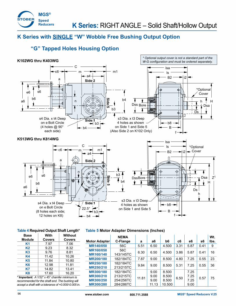
K Series with SINGLE “W” Wobble Free Bushing Output Option
“G” Tapped Holes Housing Option
K102WG thru K403WG
K513WG thru K814WG
* Optional output cover is not a standard part of the W-G configuration and must be ordered separately.
Table 4 Required Output Shaft Length*Base
ModuleWith
CoversWithout Covers
K1 7.97 7.06K2 9.23 8.32K3 9.76 8.81K4 11.42 10.26K5 11.84 10.80K6 12.98 11.81K7 14.82 13.41K8 17.60 16.20
* Important: A 1/32” x 45° chamfer minimum is recommended for the shaft end. The bushing will accept a shaft with a tolerance of +0.000/-0.005 in.
Table 5 Motor Adapter Dimensions (Inches)
Motor AdapterNEMA
C-Flange a a6 b6 c6 e6 s6Wt. lbs.
MR14 0/050 56C 5.51 6.50 4.500 3.31 5.87 0.41 9MR160/050MR160/140
56C143/145TC 6.30 6.50 4.500 3.86 5.87 0.41 16
MR200/180 182/184TC 7.87 9.00 8.500 4.80 7.25 0.55 23MR250/180MR250/210
182/184TC213/215TC 9.84 9.00 8.500 5.31 7.25 0.55 36
MR300/180MR300/210MR300/250MR300/280
182/184TC213/215TC254/256TC284/286TC
11.81
9.009.009.0011.13
8.5008.5008.500
10.500
6.50
7.257.257.259.00
0.57 75
MGS® Speed Reducers V.25 97www.stober.com 800.711.3588
KR
IGH
T AN
GLE
– Solid S
haft/Hollow
Output
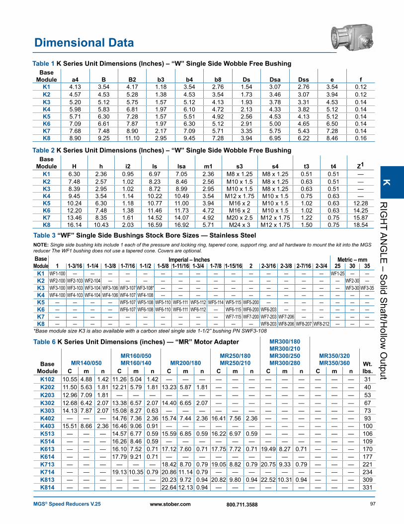
Dimensional DataTable 1 K Series Unit Dimensions (Inches) – “W” Single Side Wobble Free Bushing
Base Module a4 B B2 b3 b4 b8 Ds Dsa Dss e f
K1 4.13 3.54 4.17 1.18 3.54 2.76 1.54 3.07 2.76 3.54 0.12K2 4.57 4.53 5.28 1.38 4.53 3.54 1.73 3.46 3.07 3.94 0.12K3 5.20 5.12 5.75 1.57 5.12 4.13 1.93 3.78 3.31 4.53 0.14K4 5.98 5.83 6.81 1.97 6.10 4.72 2.13 4.33 3.82 5.12 0.14K5 5.71 6.30 7.28 1.57 5.51 4.92 2.56 4.53 4.13 5.12 0.14K6 7.09 6.61 7.87 1.97 6.30 5.12 2.91 5.00 4.65 6.50 0.14K7 7.68 7.48 8.90 2.17 7.09 5.71 3.35 5.75 5.43 7.28 0.14K8 8.90 9.25 11.10 2.95 9.45 7.28 3.94 6.95 6.22 8.46 0.16
Table 2 K Series Unit Dimensions (Inches) – “W” Single Side Wobble Free BushingBase
Module H h i2 ls lsa m1 s3 s4 t3 t4 Z1K1 6.30 2.36 0.95 6.97 7.05 2.36 M8 x 1.25 M8 x 1.25 0.51 0.51 —K2 7.48 2.57 1.02 8.23 8.46 2.56 M10 x 1.5 M8 x 1.25 0.63 0.51 —K3 8.39 2.95 1.02 8.72 8.99 2.95 M10 x 1.5 M8 x 1.25 0.63 0.51 —K4 9.45 3.54 1.14 10.22 10.49 3.54 M12 x 1.75 M10 x 1.5 0.75 0.63 —K5 10.24 6.30 1.18 10.77 11.00 3.94 M16 x 2 M10 x 1.5 1.02 0.63 12.28K6 12.20 7.48 1.38 11.46 11.73 4.72 M16 x 2 M10 x 1.5 1.02 0.63 14.25K7 13.46 8.35 1.61 14.52 14.07 4.92 M20 x 2.5 M12 x 1.75 1.22 0.75 15.87K8 16.14 10.43 2.03 16.59 16.92 5.71 M24 x 3 M12 x 1.75 1.50 0.75 18.54
Table 3 “WF” Single Side Bushings Stock Bore Sizes — Stainless SteelNOTE: Single side bushing kits include 1 each of the pressure and locking ring, tapered cone, support ring, and all hardware to mount the kit into the MGS reducer The WF1 bushing does not use a tapered cone. Covers are optional.
Base Module
Imperial – Inches Metric – mm1 1-3/16 1-1/4 1-3/8 1-7/16 1-1/2 1-5/8 1-11/16 1-3/4 1-7/8 1-15/16 2 2-3/16 2-3/8 2-7/16 2-3/4 25 30 35
K1 WF1-100 — — — — — — — — — — — — — — — WF1-25 — —K2 WF2-100 WF2-103 WF2-104 — — — — — — — — — — — — — — WF2-30 —K3 WF3-100 WF3-103 WF3-104 WF3-106 WF3-107 WF3-108* — — — — — — — — — — — WF3-30 WF3-35K4 WF4-100 WF4-103 WF4-104 WF4-106 WF4-107 WF4-108 — — — — — — — — — — — — —K5 — — — — WF5-107 WF5-108 WF5-110 WF5-111 WF5-112 WF5-114 WF5-115 WF5-200 — — — — — — —K6 — — — — WF6-107 WF6-108 WF6-110 WF6-111 WF6-112 — WF6-115 WF6-200 WF6-203 — — — — — —K7 — — — — — — — — — — WF7-115 WF7-200 WF7-203 WF7-206 — — — — —K8 — — — — — — — — — — — — WF8-203 WF8-206 WF8-207 WF8-212 — — —
*Base module size K3 is also available with a carbon steel single side 1-1/2” bushing PN SWF3-108
Table 6 K Series Unit Dimensions (inches) — “MR” Motor Adapter MR300/180 MR300/210 MR300/250 MR300/280
MR350/320 MR350/360Base
ModuleMR140/050
MR160/050 MR160/140 MR200/180
MR250/180 MR250/210 Wt.
lbs.C m n C m n C m n C m n C m n C m nK102 10.55 4.88 1.42 11.26 5.04 1.42 — — — — — — — — — — — — 31K202 11.50 5.63 1.81 12.21 5.79 1.81 13.23 5.87 1.81 — — — — — — — — — 40K203 12.96 7.09 1.81 — — — — — — — — — — — — — — — 53K302 12.68 6.42 2.07 13.38 6.57 2.07 14.40 6.65 2.07 — — — — — — — — — 67K303 14.13 7.87 2.07 15.08 8.27 0.63 — — — — — — — — — — — — 73K402 — — — 14.76 7.36 2.36 15.74 7.44 2.36 16.41 7.56 2.36 — — — — — — 93K403 15.51 8.66 2.36 16.46 9.06 0.91 — — — — — — — — — — — — 100K513 — — — 14.57 6.77 0.59 15.59 6.85 0.59 16.22 6.97 0.59 — — — — — — 106K514 — — — 16.26 8.46 0.59 — — — — — — — — — — — — 109K613 — — — 16.10 7.52 0.71 17.12 7.60 0.71 17.75 7.72 0.71 19.49 8.27 0.71 — — — 170K614 — — — 17.79 9.21 0.71 — — — — — — — — — — — — 177K713 — — — — — — 18.42 8.70 0.79 19.05 8.82 0.79 20.75 9.33 0.79 — — — 221K714 — — — 19.13 10.35 0.79 20.86 11.14 0.79 — — — — — — — — — 234K813 — — — — — — 20.23 9.72 0.94 20.82 9.80 0.94 22.52 10.31 0.94 — — — 309K814 — — — — — — 22.64 12.13 0.94 — — — — — — — — — 331
MGS® Speed Reducers V.2598 www.stober.com 800.711.3588
MGS®
Speed Reducers K Series: RIGHT ANGLE – Solid Shaft/Hollow Output
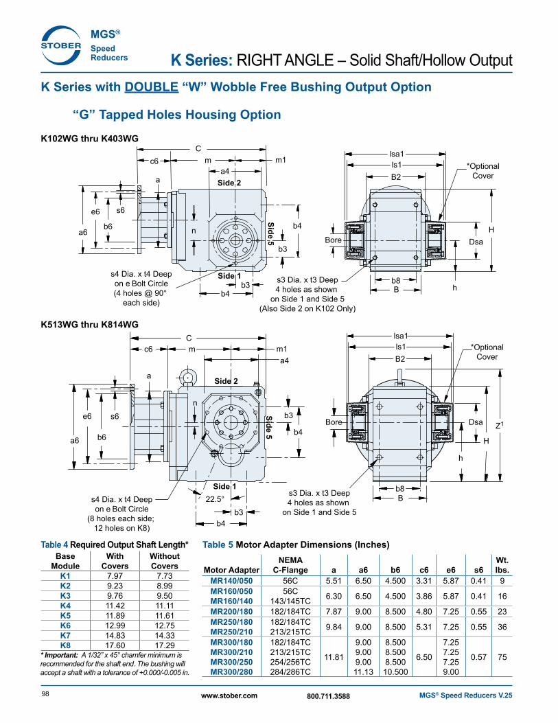
K Series with DOUBLE “W” Wobble Free Bushing Output Option
“G” Tapped Holes Housing Option
K102WG thru K403WG
K513WG thru K814WG
Cc6
a
s6
b6
e6
a6
a
m m1a4
b3
b3
n
n
Bore
b4
b3
b3
b4
22.5°
b4
b4
s3 Dia. x t3 Deep4 holes as shown
on Side 1 and Side 5(Also Side 2 on K102 Only)
Dsa
h
h
H
B2
b8B
ls1lsa1
Z1
Cm m1
a4
Bore
s3 Dia. x t3 Deep4 holes as shown
on Side 1 and Side 5
Dsa
H
b8B
Side 1
Side 2
Side 5
Side 1
Side 2
Side 5
s4 Dia. x t4 Deepon e Bolt Circle(4 holes @ 90°
each side)
*OptionalCover
*OptionalCover
c6
s6
b6
e6
a6
B2ls1lsa1
s4 Dia. x t4 Deepon e Bolt Circle
(8 holes each side; 12 holes on K8)
Table 4 Required Output Shaft Length*Base
ModuleWith
CoversWithout Covers
K1 7.97 7.73K2 9.23 8.99K3 9.76 9.50K4 11.42 11.11K5 11.89 11.61K6 12.99 12.75K7 14.83 14.33K8 17.60 17.29
* Important: A 1/32” x 45° chamfer minimum is recommended for the shaft end. The bushing will accept a shaft with a tolerance of +0.000/-0.005 in.
Table 5 Motor Adapter Dimensions (Inches)
Motor AdapterNEMA
C-Flange a a6 b6 c6 e6 s6Wt. lbs.
MR14 0/050 56C 5.51 6.50 4.500 3.31 5.87 0.41 9MR160/050MR160/140
56C143/145TC 6.30 6.50 4.500 3.86 5.87 0.41 16
MR200/180 182/184TC 7.87 9.00 8.500 4.80 7.25 0.55 23MR250/180MR250/210
182/184TC213/215TC 9.84 9.00 8.500 5.31 7.25 0.55 36
MR300/180MR300/210MR300/250MR300/280
182/184TC213/215TC254/256TC284/286TC
11.81
9.009.009.0011.13
8.5008.5008.500
10.500
6.50
7.257.257.259.00
0.57 75
MGS® Speed Reducers V.25 99www.stober.com 800.711.3588
KR
IGH
T AN
GLE
– Solid S
haft/Hollow
Output
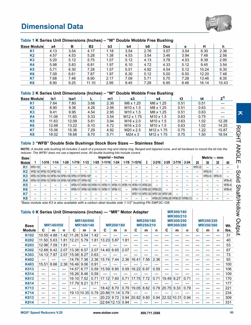
Dimensional DataTable 1 K Series Unit Dimensions (Inches) – “W” Double Wobble Free BushingBase Module a4 B B2 b3 b4 b8 Dsa e H h
K1 4.13 3.54 4.17 1.18 3.54 2.76 3.07 3.54 6.30 2.36K2 4.57 4.53 5.28 1.38 4.53 3.54 3.46 3.94 7.48 2.56K3 5.20 5.12 5.75 1.57 5.12 4.13 3.78 4.53 8.39 2.95K4 5.98 5.83 6.81 1.97 6.10 4.72 4.33 5.12 9.45 3.54K5 5.71 6.30 7.28 1.57 5.51 4.92 4.54 5.12 10.24 6.30K6 7.09 6.61 7.87 1.97 6.30 5.12 5.00 6.50 12.20 7.48K7 7.68 7.48 8.90 2.17 7.09 5.71 5.75 7.28 13.46 8.35K8 8.90 9.25 11.10 2.95 9.45 7.28 6.95 8.46 16.14 10.43
Table 2 K Series Unit Dimensions (Inches) – “W” Double Wobble Free BushingBase Module ls1 lsa1 L m1 s3 s4 t3 t4 Z1
K1 7.64 7.80 3.66 2.36 M8 x 1.25 M8 x 1.25 0.51 0.51 —K2 8.90 9.36 4.26 2.56 M10 x 1.5 M8 x 1.25 0.51 0.63 —K3 9.41 9.95 4.54 2.95 M10 x 1.5 M8 x 1.25 0.51 0.63 —K4 11.06 11.60 5.33 3.54 M12 x 1.75 M10 x 1.5 0.63 0.75 —K5 11.63 12.09 5.61 3.94 M16 x 2.0 M10 x 1.5 0.63 1.02 12.28K6 12.68 13.22 6.10 4.72 M16 x 2.0 M10 x 1.5 0.63 1.02 14.25K7 15.06 15.36 7.29 4.92 M20 x 2.5 M12 x 1.75 0.75 1.22 15.87K8 18.02 18.68 8.70 5.71 M24 x 3 M12 x 1.75 0.75 1.50 18.54
Table 3 “WFB” Double Side Bushings Stock Bore Sizes — Stainless SteelNOTE: A double side bushing kit includes 2 each of a pressure ring and clamp ring, flanged and tapered cone, and all hardware to mount the kit into the reducer. The WFB1 does not use a tapered cone. All double bushing kits include covers.
Base Module
Imperial – Inches Metric – mm1 1-3/16 1-1/4 1-3/8 1-7/16 1-1/2 1-5/8 1-11/16 1-3/4 1-7/8 1-15/16 2 2-3/16 2-3/8 2-7/16 2-3/4 25 30 35 40
K1 WFB1-100 — — — — — — — — — — — — — — — WFB1-25 — — —K2 WFB2-100 WFB2-103 WFB2-104 — — — — — — — — — — — — — — WFB2-30 — —K3 WFB3-100 WFB3-103 WFB3-104 WFB3-106 WFB3-107 WFB3-108* — — — — — — — — — — — WFB3-30 WFB3-35 —K4 WFB4-100 WFB4-103 WFB4-104 WFB4-106 WFB4-107 WFB4-108 — — — — — — — — — — — — — WFB4-40K5 — — — — WFB5-107 WFB5-108 WFB5-110 WFB5-111 WFB5-112 WFB5-114 WFB5-115 WFB5-200 — — — — — — — WFB5-40K6 — — — — WFB6-107 WFB6-108 WFB6-110 WFB6-111 WFB6-112 — WFB6-115 WFB6-200 WFB6-203 — — — — — — WFB6-40K7 — — — — — — — — — — WFB7-115 WFB7-200 WFB7-203 WFB7-206 — — — — — —K8 — — — — — — — — — — — — WFB8-203 WFB8-206 WFB8-207 WFB8-212 — — — —
*Base module size K3 is also available with a carbon steel double side 1-1/2” bushing PN SWF3C-108
Table 6 K Series Unit Dimensions (inches) — “MR” Motor Adapter MR300/180 MR300/210 MR300/250 MR300/280
MR350/320 MR350/360Base
ModuleMR140/050
MR160/050 MR160/140 MR200/180
MR250/180 MR250/210 Wt.
lbs.C m n C m n C m n C m n C m n C m nK102 10.55 4.88 1.42 11.26 5.04 1.42 — — — — — — — — — — — — 31K202 11.50 5.63 1.81 12.21 5.79 1.81 13.23 5.87 1.81 — — — — — — — — — 40K203 12.96 7.09 1.81 — — — — — — — — — — — — — — — 53K302 12.68 6.42 2.07 13.38 6.57 2.07 14.40 6.65 2.07 — — — — — — — — — 67K303 14.13 7.87 2.07 15.08 8.27 0.63 — — — — — — — — — — — — 73K402 — — — 14.76 7.36 2.36 15.74 7.44 2.36 16.41 7.56 2.36 — — — — — — 93K403 15.51 8.66 2.36 16.46 9.06 0.91 — — — — — — — — — — — — 100K513 — — — 14.57 6.77 0.59 15.59 6.85 0.59 16.22 6.97 0.59 — — — — — — 106K514 — — — 16.26 8.46 0.59 — — — — — — — — — — — — 109K613 — — — 16.10 7.52 0.71 17.12 7.60 0.71 17.75 7.72 0.71 19.49 8.27 0.71 — — — 170K614 — — — 17.79 9.21 0.71 — — — — — — — — — — — — 177K713 — — — — — — 18.42 8.70 0.79 19.05 8.82 0.79 20.75 9.33 0.79 — — — 221K714 — — — 19.13 10.35 0.79 20.86 11.14 0.79 — — — — — — — — — 234K813 — — — — — — 20.23 9.72 0.94 20.82 9.80 0.94 22.52 10.31 0.94 — — — 309K814 — — — — — — 22.64 12.13 0.94 — — — — — — — — — 331
MGS® Speed Reducers V.25100 www.stober.com 800.711.3588
MGS®
Speed Reducers K Series: RIGHT ANGLE – Solid Shaft/Hollow Output
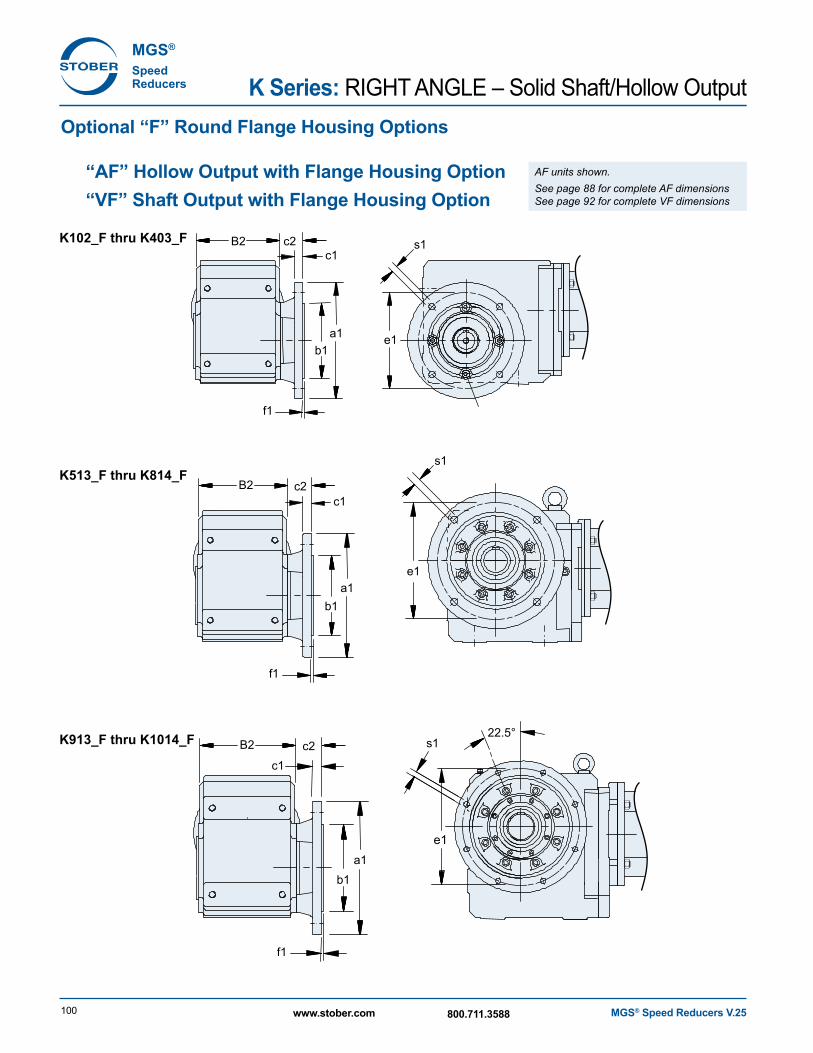
Optional “F” Round Flange Housing Options “AF” Hollow Output with Flange Housing Option “VF” Shaft Output with Flange Housing Option
s1
s1
s1
e1
e1
e1b1
a1
B2
B2
c2
f1
c1
c1
b1a1
f1
b1a1
f1
c1
22.5°
c2
B2 c2
K102_F thru K403_F
K913_F thru K1014_F
K513_F thru K814_F
AF units shown. See page 88 for complete AF dimensions See page 92 for complete VF dimensions
MGS® Speed Reducers V.25 101www.stober.com 800.711.3588
KR
IGH
T AN
GLE
– Solid S
haft/Hollow
Output
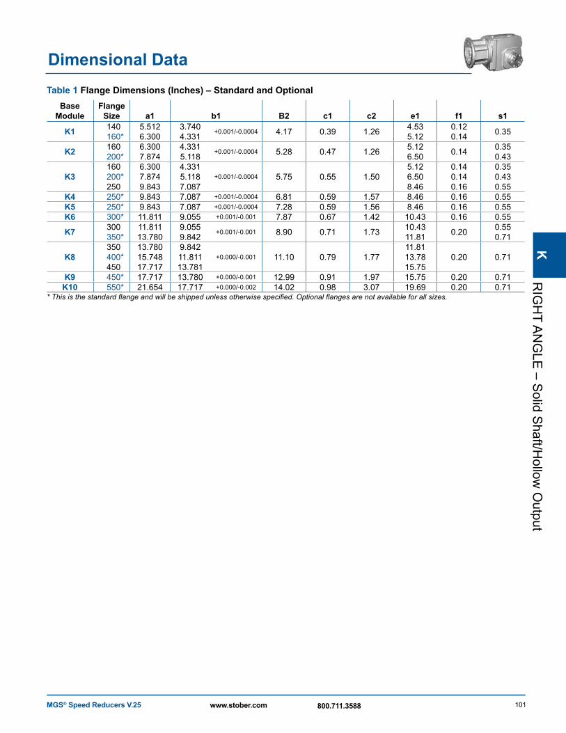
Table 1 Flange Dimensions (Inches) – Standard and OptionalBase
ModuleFlange
Size a1 b1 B2 c1 c2 e1 f1 s1
K1 140160*
5.5126.300
3.7404.331
+0.001/-0.0004 4.17 0.39 1.26 4.535.12
0.120.14 0.35
K2 160200*
6.3007.874
4.3315.118
+0.001/-0.0004 5.28 0.47 1.26 5.126.50 0.14 0.35
0.43
K3160200*250
6.3007.8749.843
4.3315.1187.087
+0.001/-0.0004 5.75 0.55 1.505.126.508.46
0.140.140.16
0.350.430.55
K4 250* 9.843 7.087 +0.001/-0.0004 6.81 0.59 1.57 8.46 0.16 0.55K5 250* 9.843 7.087 +0.001/-0.0004 7.28 0.59 1.56 8.46 0.16 0.55K6 300* 11.811 9.055 +0.001/-0.001 7.87 0.67 1.42 10.43 0.16 0.55
K7 300350*
11.81113.780
9.0559.842
+0.001/-0.001 8.90 0.71 1.73 10.4311.81 0.20 0.55
0.71
K8350400*450
13.78015.74817.717
9.84211.81113.781
+0.000/-0.001 11.10 0.79 1.7711.8113.7815.75
0.20 0.71
K9 450* 17.717 13.780 +0.000/-0.001 12.99 0.91 1.97 15.75 0.20 0.71K10 550* 21.654 17.717 +0.000/-0.002 14.02 0.98 3.07 19.69 0.20 0.71
* This is the standard flange and will be shipped unless otherwise specified. Optional flanges are not available for all sizes.
Dimensional Data