Embed Size (px)
Citation preview
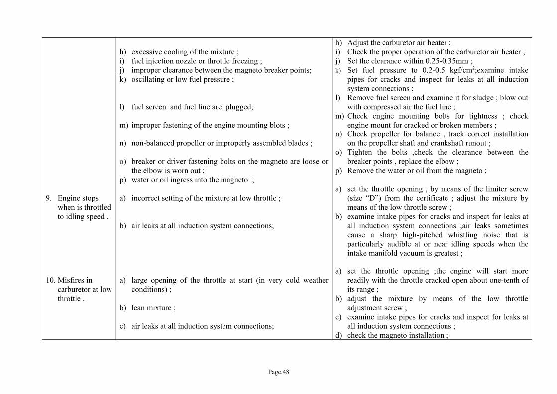
9. Engine stops when is throttled to idling speed .
10. Misfires in carburetor at low throttle .
h) excessive cooling of the mixture ;i) fuel injection nozzle or throttle freezing ;j) improper clearance between the magneto breaker points;k) oscillating or low fuel pressure ;
l) fuel screen and fuel line are plugged;
m) improper fastening of the engine mounting blots ;
n) non-balanced propeller or improperly assembled blades ;
o) breaker or driver fastening bolts on the magneto are loose or the elbow is worn out ;
p) water or oil ingress into the magneto ;
a) incorrect setting of the mixture at low throttle ;
b) air leaks at all induction system connections;
a) large opening of the throttle at start (in very cold weather conditions) ;
b) lean mixture ;
c) air leaks at all induction system connections;
h) Adjust the carburetor air heater ;i) Check the proper operation of the carburetor air heater ;j) Set the clearance within 0.25-0.35mm ;k) Set fuel pressure to 0.2-0.5 kgf/cm2;examine intake
pipes for cracks and inspect for leaks at all induction system connections ;
l) Remove fuel screen and examine it for sludge ; blow out with compressed air the fuel line ;
m) Check engine mounting bolts for tightness ; check engine mount for cracked or broken members ;
n) Check propeller for balance , track correct installation on the propeller shaft and crankshaft runout ;
o) Tighten the bolts ,check the clearance between the breaker points , replace the elbow ;
p) Remove the water or oil from the magneto ;
a) set the throttle opening , by means of the limiter screw (size “D”) from the certificate ; adjust the mixture by means of the low throttle screw ;
b) examine intake pipes for cracks and inspect for leaks at all induction system connections ;air leaks sometimes cause a sharp high-pitched whistling noise that is particularly audible at or near idling speeds when the intake manifold vacuum is greatest ;
a) set the throttle opening ;the engine will start more readily with the throttle cracked open about one-tenth of its range ;
b) adjust the mixture by means of the low throttle adjustment screw ;
c) examine intake pipes for cracks and inspect for leaks at all induction system connections ;
d) check the magneto installation ;
Page.48
11. High speed at low throttle .
12. Faulty acceleration .
13. Engine rapping .
14. Overheated engine cylinder heads and high oil temperature.
d) the magneto is installed incorrectly ;e) magneto wires were not properly connected;
f) clogged jets ;g) fuel screen is plugged ;h) low fuel pressure ;
a) improper adjustment of the carburetor low throttle limiter ;b) large opening of the throttle because of the improper
adjustment of the control rod length ;c) clearances in the throttle control system ;
a) insufficiently heated or too cold engine ;
b) incorrect adjustment of the pilot’s throttle lever ;
c) lean mixture ;d) the primer pump jets is incorrectly selected ;
a) the magneto is not timed correctly ;
b) low octane value fuel ;c) high clearances between push rod and rocker arm ;
a) insufficient oil cooling in the oil cooler ;
b) oil cooler honeycomb is clogged up ;c) frozen oil in the oil cooler ;d) faulty pumping of oil from the engine ;
e) gas seeps in the crankcase ;
e) check the correct connection of the wire to the spark plugs ;
f) check the jets ;g) Remove fuel screen and examine it for sludge ;h) Set fuel pressure to 0.15 kgf/cm2 at low throttle ;
a) adjust the low throttle screw ;b) make sure that the pilot’s lever is completely opening
the butterfly in the carburetor ; adjust the rod length;c) remove the clearances ;
a) warm the engine up to the temperature of the cylinder heads min. 120°C;
b) make sure that the pilot’s lever is completely opening the butterfly in the carburetor ; adjust the rod length ;
c) clean the fuel and air jets,clean the fuel screen ; d) replace the jet;
a) check magneto breaker points for proper timing as described in paragraphs 9.4.2 ;
b) Check the fuel octane value ; it shall be min. 91 ;c) If necessary , adjust the clearance between push rod and
rocker arm as per par.8.9.2 .
a) Check if the oil cooler valve is completely opened ; add oil to level in the oil tank ;
b) Clean the oil cooler honeycomb ;c) Heat the oil cooler ;d) Check quantity and quality of supply in the main oil
tank ;e) Check compression by pulling the propeller in the
direction of rotation to determine that each cylinder has good compression and is about even .Excessive
Page.49
15. Excessive discharge of oil fumes .
f) lean mixture ;
g) failures of the master rod bearing or other internal parts ;
h) failure of the transducer or their wires ;i) long running of the engine at high pitch ;j) air overheating at carburetor intake as a result of the
improper use of the carburetor air heater ;k) improper valve operation ;the valves are not seating well ;
l) burnt valves ;m) incorrectly set the clearances of the valves ;n) defective ignition ;o) low octane value fuel ;p) ingress of exhaust gases in the transducer aria ;
q) ingress of the exhaust gases in the cylinder heads ;Remark : The works of item 14a,14e,14k,14l,14p shall be performed by the representative of the engine manufacturing plant .
a) the piston is burnt or scratched ; the cylinder is out of roundness ;
b) excessively rich mixture ;
discharge of oil or oil fumes from the crankcase breather or thrust bearing is caused by “blow-by’ and increased crankcase pressure ,usually due to worn or damaged piston or piston rings ;
f) Check for lean mixture in any or all cylinders . This could result from improper setting of the carburetor ,air leaks in the induction system , loose carburetor bolts or bent carburetor mounting pad flange ;
g) Check oil strainer for metal deposits indicating failure in the master rod bearing or other internal parts ;
h) Check the transducer or replace the wires ;i) Switch the propeller on low pitch ;j) Move control to “cold” position ;k) Check compression by pulling the propeller in the
direction of rotation to determine that each cylinder has good compression ;replace the valves ;
l) replace the valves ;m) set the clearances as per par. 8.9.2 ;n) check ignition timing ;o) check the octane value that must be min.91;p) if the gases come out below the spark plug , dismantle
the cylinder and sent it to repair ;q) obstruct the ingress of gases ;
a) Check compression by pulling the propeller in the direction of rotation to determine that each cylinder has good compression ;if the piston is scratched or burnt it must be replaced ;
b) Clean the air jets and the carburetor air channels ; set mixture “lean” as necessary ;
Page.50
16. Low oil pressure.
17. Engine not able to develop a complete
c) faulty oil pumping ;
d) excessive oil filling of the crankcase ;e) induction system oil leaks excessively ;
f) worn or damaged piston rings ;g) critical wear of the cylinder surfaces ;Remark: the works of item 15a,15f,15g shall be performed by representatives of the engine manufacturing plant .
a) air lock in the main oil line from the tank to the input side of the oil pressure pump ;oil got thicker (in winter) ;oil drain pipe from the tank is clogged .
b) the oil pressure gauge is defective ;c) incorrect adjustment of the oil pressure pump relief valve ;
d) oil is diluted too mach with gasoline ;e) oil screen or the main oil line is clogged ;f) loosening or damage of relief valve spring ;g) oil foaming ;h) oil low level in the oil tank ;i) high wear of the parts (after long running) incorrect assembly
(after repair or internal failures of the engine) ;
a) incorrectly adjusted propeller governor or propeller set on high pitch ;
b) defective tachometer or wire ;
c) Inspect the main oil line from the tank to the input side of the oil pump for air leaks which will cause the pump to starve for oil ;check oil strainer ; check main oil line and oil cooling radiator ;
d) Check the operating of the oil pump ;e) Check the induction system for oil leaks ; If it is oily,
send the engine to repair ;f) Replace the damaged piston rings .g) Send the cylinders to repair ;
a) carefully inspect the main oil line from the tank to the input side of the pressure pump for air leaks which will cause the pump to starve for oil ; heat oil (in winter) ; check oil drain pipe from the tank for clogged condition and clean it as necessary ;
b) replace the oil pressure gauge and check the wire ;c) inspect the oil pressure relief valve to be sure that
plunger is operating smoothly in its guide and is seating well , and that the control spring is functioning properly;
d) replace oil and check for leaks at the cock;e) check the main oil line and clean the screen oil ;f) replace the valve or the spring ;g) clean and check the oil line and replace the oil ;h) add oil to the normal level in the oil tank ;i) dismantle the engine for reassemble ;
a) check propeller for correct model and setting ;
b) check the instrument and visually inspect the wire ;c) see item 14;
Page.51
revolution (low power ;
18. Propeller can not be switched from low pitch to high pitch .
19. Slow switch of the propeller in winter .
c) engine overheating ;d) carburetor sieve is clogged ;e) the throttle does not open completely ;
f) low quantity of fuel in the carburetor ;
g) defective ignition ;
h) magnetos are not in full advance ;i) incorrectly set carburetor or the pointer is locked ;j) complete burning of the exhaust valves ;k) appreciable increased clearance between push rod and rocker
arm ;
Remark : the works of item 17j shall be performed by representatives of the engine manufacturing plant.
a) frozen oil in the propeller cylinder ;
b) improperly installed propeller ;
a) oil gets thicker in the propeller cylinder during airplane parking;
d) check the carburetor for proper setting and functioning ;e) make sure that the pilot’s lever is completely opening
the butterfly in the carburetor ;f) see that an unrestricted flow of gasoline is available at
the carburetor ;g) check ignition system operation , especially for
cylinders which cut out periodically , due to failure of spark plugs , ignition wiring , or sticking of magneto points . Be sure that the magneto is functioning properly. Especially under low power conditions, ascertain that the magneto breaker point has minimum clearance behind the point arm when points themselves have their required clearance . Be sure magnetos are in full advance . If necessary ,check ignition timing ;
h) see item (g) ;i) check the carburetor for proper setting and functioning ;j) replace the valves ;k) check all valves ; any valves having an appreciable
increased clearance will indicate cam ring , push rod ,or rocker arm trouble . It is impossible for the engine to jump valve timing ;
a) heat the propeller cylinder with hot air .Make a switch of the propeller pitch multiple of 3 ;
b) check the propeller for correct model and setting ;
a) switch the propeller from low pitch to high pitch and vice versa ;
Page.52
20. Fuel leaks from the carburetor fuel injection nozzle .
21. Oil splash through the breather .
22. The compressor not provide the normal air pressure in the air tank .
23. The signaling screen lamp is lit.
24. Oil is leaking through the breather holes or from the magneto mounting flange.
a) ingress of the impurities under the fuel valve ;
a) overheated engine ;b) damaged piston rings ;c) breather holes are clogged ;d) water in oil ;
a) air leaks in the air compressed system ;b) inadequate condition of the relief valve gasket ;c) leaks at the starting valve, relief valve and piston valve ;d) compressor air screen is clogged up ;e) frozen condense inside the air compressor or on the
compressed air line ;f) cutting of the protection sleeve pins ;Remark : the works of item 22c shall be performed by representatives of the engine manufacturing plant.
a) metal deposit in the oil screen ;
b) failures of the signaling screen lamp wiring ;c) water in oil ;
a) accumulation of oil in the magneto drive ;
a) clean the fuel valve by flowing fuel through the lower drain plug ;
a) proceed as in item 14 ;b) find the defective cylinder and replace the piston rings ;c) clean the breather ;d) replace oil ;
a) inspect for leaks at all air compressed system ;b) check for a shrunken gasket ;c) replace the air compressor ;d) clean the screen ;
e) heat the compressor and the compressed air line ; install a new sleeve from the spare parts kit ,by previously rotating the air compressor with the wrench ;
a) check oil strainer for metal deposit indicating failure in the master rod bearing or other internal parts ;
b) check the signaling screen lamp wiring ;c) replace oil from the engine ;
a) remove the drain plug and drain the oil ;
Page.53
11. ENGINE STORAGE , RETURNING TO SERVICE FROM STORAGE AND PRESERVATION
Engine storage is one of the main steps of engine protection that is providing its integrity during preservation and the trouble free operation . The engine that are temporarily unused shall be stored correctly and at due time , by using the materials recommended for these operations .
11.1 Materials used for engine storage
11.1.1The following lubricants shall be used for the storage of the temporarily unused engines and the spare parts :
a- MK-22 or MS-20 GOST 21743-76 engine oil for the internal storage of the engine and its aggregates up to 30 days , and for the carburetor and fuel pump up to 6 years .
b- OST 38.1.56-74 technical grease – for the storage of the unpainted parts up to 60 days , for the lubrication of the polyethylene hood and tools on board for 6 years .
c- GOST 19537-74 or PVK GOST 19537-74 grease for the internal preservation of the magneto for 6 years .
d- K-17 GOST 10877076 storage oil for the internal and external preservation of the engine and its aggregates (excepting the carburetor and fuel screen or fuel pump)up to 6 years .
WARNING : 1. It is forbidden to use the K-17 oil for the internal storage of the carburetor , the fuel screen
and fuel pump .2. The grease and oil for storage , gasoline and the paraffin paper shall be periodically subject
to a lab inspection in order to define their validity .3. In order to completely remove the humidity , heat the technical grease , the PVK grease up
to 110-120°C before use , till the foam disappears .
11.1.2 Before storage , the K-17 storage oil shall be heated up to 30-40°C for the internal and external storage of the engine .
11.2 Storage of the engine as installed on the airplane.
11.2.1 The airplanes may be stored with the engines installed on them in hangars and under air field conditions .In both cases , the engine must be protected against corrosion , depending on the period planned to stop engine operation.
11.2.2 If the engine is not going to operate for a long time , after seven days at most of standing , the engine shall be stored depending on the period planned for standing according to one of the methods mentioned above .
11.2.3 In case the airplane with the engine installed is parked in open air , protect the engine cowling with a tight hood against rainfall , snow and dust . It is forbidden to store the engine under rain or snowfall conditions .
11.2.4 Write the date of storage and corrosion cases in the engine logbook and aggregates certificates .
11.3 20 days storage of the engine as installed on the airplane
11.3.1 Start and warm up the engine , as per chapter 8.2 ;11.3.2 After the run-in period (10-15 minutes) at 35-41%(1000-1200r.p.m.) with the B-70
GOST 1012-72 gasoline and the oil used in operation is completed , stop the engine ;11.3.3 Let the cylinder heads to cool up to 30-40°C ;
Page.54
11.3.4 Unscrew the front spark plugs . Turn the propeller over by hand 8-10 complete revolutions with switch “Off” and throttle completely open in order to release the exhaust gases from the cylinders ;
11.3.5 Spray interior of cylinders 70-100g of MK-22 or MS-20 clean engine oil , dehydrated and heated up to 60-80°C . Refit the spark plugs ;
11.3.6 Wipe the external surfaces of the engine with a clean cloth ,soaked in the B-70 gasoline , and the durite joints with a dry ,clean cloth ;
11.3.7 When the ambient is higher than 0°C , turn from 10 to 10 days the engine in its direction of rotation 6-8 complete revolutions , with the throttle completely open;Remarks: It is allowed to store the engine in compliance with item 11.3.1 –11.3.7 of this chapter , by using the B-91/115 (GOST 1012-72). In this case the storage period is max. 15 days .
11.3.8 In case of an extension of the storage period higher than 20 days , and in case of storage with B-91/115 gasoline more than 15 days , make the engine storage, as per items 11.3.1 ;Remark : It is allowed in both cases to restore the engine for max. three times , then it is necessary to prepare for storage the engine at fixed term, up to 30-90 days.
11.3.9 The engine stored for 15 or 20 days shall not be returned to service from storage .
11.4 Storage and preparation of the engine installed on the airplane for service after a storage period of 30 days
11.4.1 Start and warm up the engine according to the specifications of chapter 8.2 ;11.4.2 Stop the engine , drain oil from the oil tank and engine immediately . Fill the oil tank
with fresh oil and the fuel tank with the B-70 GOST-72 gasoline ;11.4.3 Start the engine and let it run 10-15 minutes at 35-44%(1000-1200r.p.m.) ;11.4.4 Stop the engine and let the cylinder heads to cool up to 30-40°C ;11.4.5 Unscrew the front spark plugs , disconnect the pipe from the air compressor
discharge valve connection . Dismantle the circlip , the sieve of the screen and spray interior of air compressor MK-22 or MS-20 oil (heated up to 60-80°C) through intake valve , rotating at the same time the propeller shaft till oil leaks from the discharge valve ;
11.4.6 Spray interior of cylinders 70-100 g clean engine oil through the holes provided for spark plugs . Spray also all valves , then rotate the propeller shaft 2-3 complete revolutions . Refit the parts set forth in para.11.4.5 ;
11.4.7 Spray again 70-100 g of clean engine oil , dehydrated and heated to 60-80°C ,into each cylinder through the holes provided for the spark plugs . In this case do not rotate the propeller;
11.4.8 Spray interior of fuel screen with heated oil (60-70°C) , up to complete filling of the internal cavity and removal of the air bubbles . Then drain the oil from the internal cavity . Connect the fuel pipes ;
11.4.9 Prepare for storage the carburetor by performing the following operations :a- set the throttle valve on the limiter for a complete opening ;b- unscrew plug 3 (Fig.11) of the selfactuated manifold and the drain plug 2
(Fig.12) ;c- disconnect the pipes from fuel carburetor inlet connection 6 (Fig.12) and from
the measuring fuel pressure connection 7 (Fig.12) ;d- unscrew the transportation plug from connection 7 , and stud 6 is connected to
the manual pump filled with engine oil (MK-22 or MS-20) heated to 60-80°C;e- open the fuel valve by unscrewing plug 6 (Fig.11) for measuring air pressure
within the air cavity and set air under a pressure of 0.3-0.5kgf/cm2 ;f- pump heated oil (up to 60-70°C) inside the carburetor , under a pressure of 0.3-
0.5kgf/cm2 ,till oil appears in the hole for plug 2 (Fig.12) , then this plug is screwed back and continue pumping till oil appears in the hole of plug 3 (Fig.11), then screw in this plug and continue pumping till oil appears in the fuel injection nozzle ;
Page.55