Embed Size (px)
Citation preview
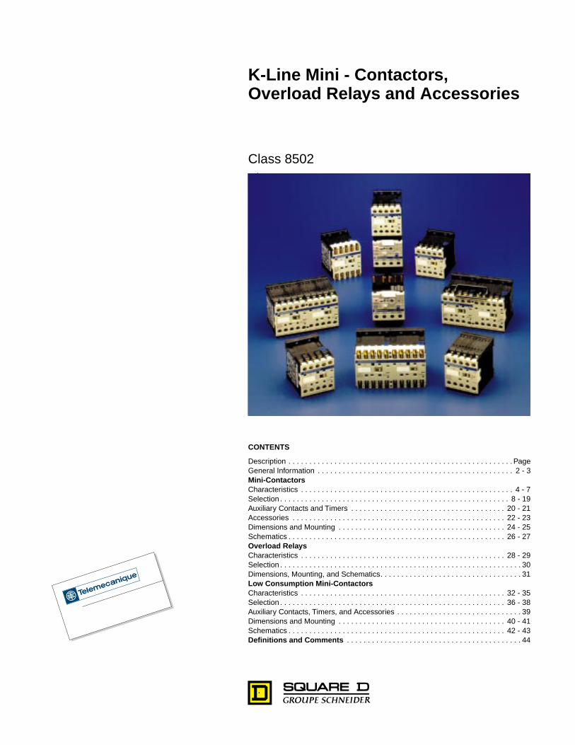
K-Line Mini - Contactors, Overload Relays and Accessories
Class 8502
CONTENTS
Description . . . . . . . . . . . . . . . . . . . . . . . . . . . . . . . . . . . . . . . . . . . . . . . . . . . . . . PageGeneral Information . . . . . . . . . . . . . . . . . . . . . . . . . . . . . . . . . . . . . . . . . . . . . . . 2 - 3
Mini-Contactors
Characteristics . . . . . . . . . . . . . . . . . . . . . . . . . . . . . . . . . . . . . . . . . . . . . . . . . . . 4 - 7Selection . . . . . . . . . . . . . . . . . . . . . . . . . . . . . . . . . . . . . . . . . . . . . . . . . . . . . . . 8 - 19Auxiliary Contacts and Timers . . . . . . . . . . . . . . . . . . . . . . . . . . . . . . . . . . . . . 20 - 21Accessories . . . . . . . . . . . . . . . . . . . . . . . . . . . . . . . . . . . . . . . . . . . . . . . . . . . 22 - 23Dimensions and Mounting . . . . . . . . . . . . . . . . . . . . . . . . . . . . . . . . . . . . . . . . 24 - 25Schematics . . . . . . . . . . . . . . . . . . . . . . . . . . . . . . . . . . . . . . . . . . . . . . . . . . . . 26 - 27
Overload Relays
Characteristics . . . . . . . . . . . . . . . . . . . . . . . . . . . . . . . . . . . . . . . . . . . . . . . . . 28 - 29Selection . . . . . . . . . . . . . . . . . . . . . . . . . . . . . . . . . . . . . . . . . . . . . . . . . . . . . . . . . . 30Dimensions, Mounting, and Schematics. . . . . . . . . . . . . . . . . . . . . . . . . . . . . . . . . . 31
Low Consumption Mini-Contactors
Characteristics . . . . . . . . . . . . . . . . . . . . . . . . . . . . . . . . . . . . . . . . . . . . . . . . . 32 - 35Selection . . . . . . . . . . . . . . . . . . . . . . . . . . . . . . . . . . . . . . . . . . . . . . . . . . . . . . 36 - 38Auxiliary Contacts, Timers, and Accessories . . . . . . . . . . . . . . . . . . . . . . . . . . . . . . 39Dimensions and Mounting . . . . . . . . . . . . . . . . . . . . . . . . . . . . . . . . . . . . . . . . 40 - 41Schematics . . . . . . . . . . . . . . . . . . . . . . . . . . . . . . . . . . . . . . . . . . . . . . . . . . . . 42 - 43
Definitions and Comments
. . . . . . . . . . . . . . . . . . . . . . . . . . . . . . . . . . . . . . . . . . 44
K-Line Mini-Contactors, Overload Relays and Accessories
General Information
© 1998 Square D All Rights Reserved
2
5/98
Introduction
The Telemecanique family of IEC style contactors and starters are the largest selling motor control devices in the world. When the application calls for world class products, select the Telemecanique IEC style contactors and starters for products that are marketed and sold in over 160 countries. Most devices are UL listed, CSA certified, CE marked, meet IEC 947 standards and are approved by most other international approved agencies.
The Telemecanique family of IEC style contactors and starters include the following:
K-Line mini-contactors and overload relays
are for general purpose starting and protection in a small package for motor loads up to 12 Amps or resistive loads up to 20 Amps.
D-Line contactors and overload relays
offer the largest offering of accessories for maximum flexibility in customer applications and automated systems up to 150 motor full-load Amps or 200 Amp resistive loads.
F-Line contactors and solid-state overload relays
are for inductive loads up to 800 Amps or resistive loads up to 1350 Amps and share common accessories with the D-Line.
GV manual starters
provide manual isolation, manual motor control and overcurrent protection in one compact unit. They are approved for Group Motor Installations when used alone or with D-Line contactors.
Integral self-protected starters
combine all the functions of a disconnect switch, circuit breaker, contactor and overload relay in one coordinated unit to reduce required panel space by as much as 60% and reduce installation and wiring time.
Selection of Telemecanique K-Line, D-Line and F-Line contactors are based on Utilization Categories, a combination of application and duty cycle rates defined by the following:
• The type of application (inductive motor loads or resistive loads)• The conditions under which making or breaking current takes place (motor starting or running,
reversing, plugging or jogging, locked rotor or stalled motor)• Number of making and breaking operations (or cycles) required for the life of the contactor
When specifying Telemecanique IEC contactors and starters refer to the following Square D documents:
Catalog No. 8502CT9801 IEC Contactors Selection GuideCatalog No. 8502CT9703 K-Line Contactors, Overload Relays and AccessoriesCatalog No. 8502CT9704 D-Line Contactors, Overload Relays and AccessoriesCatalog No. 8502CT9702 F-Line Contactors, Overload Relays and AccessoriesCatalog No. 2520CT9501 GV2/GV3 Manual Starters and AK5 Panel Busbar SystemCatalog No. 8539CT9201 Integral Self-Protected Starters
K-Line Mini-Contactors, Overload Relays and Accessories
General Information
3
5/98 © 1998 Square D All Rights Reserved
The K-Line Mini-Contactors and Overload Relays are ideal for general duty applications where small size and reliability are key concerns.
Three contactor ratings
The K-Line mini-contactors are available in three ratings for the USA market.
K06 rated for 3 hp motors at 480 VAC or 600 VACK09 rated for 5 hp motors at 480 VAC or 600 VACK12 rated for 7.5 hp motors at 480 VAC or 10 hp at 600 VAC
Space savings
The special magnet and armature structure allow for a DC coil-operated device with the same physical size and panel footprint of the AC coil version.
IP20 rated finger-safe terminals with both North American and International terminal markings
Mounts on 35mm DIN rail or panel mount with screws
Available in 3-pole contactor versions with built-in auxiliary contact for holding circuit or 4-pole contactor versions
Easily installed accessories
2-pole or 4-pole instantaneous auxiliary contact blocks with:
Screw clamp or slip-on terminals,Transient voltage surge suppressorsElectronic 1 to 30 second On-delay timers
Three wiring methods to reduce installation time
Captive screw terminals for use with either Phillips or slotted head screwdrivers, slip-on terminals for quick installation of single 1/4" or double 1/8" tabs, or terminal pins for soldering the contactor directly to a printed circuit board.
Control circuit flexibility
All versions of the K-Line mini-contactors are available with an AC, DC, or low consumption DC operating coil. The low consumption DC coil operating device can be energized by a low level DC signal from a computer or PLC and includes built-in transient suppression and LED “On” indicator.
Bimetallic overload relays
The K-Line Class 10 bimetallic overload relays are ambient-compensated and include single-phase sensitivity for phase unbalance and phase loss protection. Standard features include isolated N.C. trip contact and N.O. alarm contact, manual or automatic reset function, tamper resistant window for FLA settings and Test trip button. Five pins connect to the contactor load side terminals, three for the power circuit and two for the control circuit which eliminate customer wiring for the 3-wire control holding circuit.
K-Line Mini-Contactors, Overload Relays and Accessories
Characteristics
© 1998 Square D All Rights Reserved
4
5/98
Type LC
k
K and LP
k
K contactors
Environment
Rated insulation voltage
(Ui)
Conforming to IEC 947 V 690
Conforming to VDE 0110 gr C V 750
Conforming to BS 5424, NF C 20-040 V 690
Conforming to CSA 22-2 No. 14, UL 508 V 600
Rated impulse withstand voltage
(Uimp) kV 8
Conforming to standards
Meets the essential requirements of the LV & EMC directives
IEC 947, NF C 63-110, VDE 0660, BS 5424, UL508, CSA 22-2 No. 14
Approvals
LC
k
-K06, LC
k
-K09, LC
k
-K12LP
k
-K06, LP
k
-K09, LP
k
-K12
E164862NLDX(Screw Clamp)
E164862NLDX2(Slip-on & Solder Pin)
LR 43364 3211-04
Protective treatment
Conforming to IEC 68 (DIN 50016) “TC” (Fungus-proof, tropicalization protection)
Degree of protection
Conforming to VDE 0106 Protection against direct finger contact
Ambient air temperature
around the device
Storage - 50
°
to + 80
°
C (-58
°
to +176
°
F)
Operation - 25
°
to + 50
°
C (-13
°
to +122
°
F)
Maximum operating altitude
Without derating 2000 m (6562 ft)
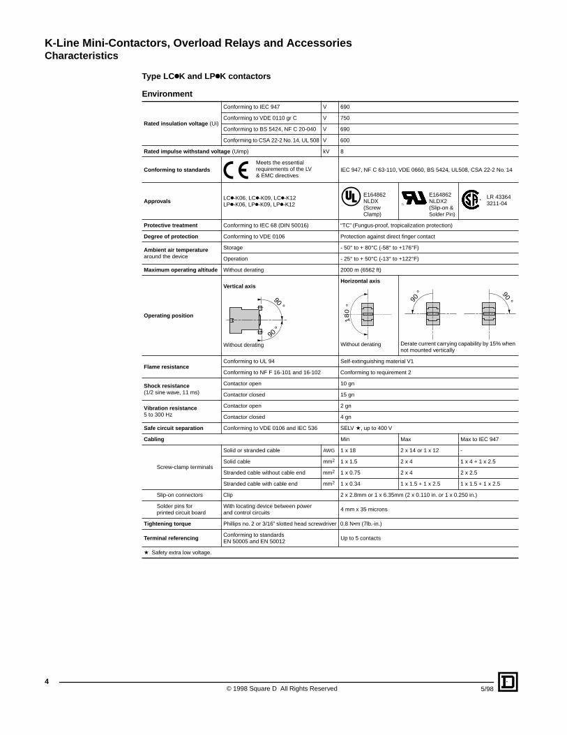
Operating position
Vertical axis
Without derating
Horizontal axis
Without derating Derate current carrying capability by 15% when not mounted vertically
Flame resistance
Conforming to UL 94 Self-extinguishing material V1
Conforming to NF F 16-101 and 16-102 Conforming to requirement 2
Shock resistance
(1/2 sine wave, 11 ms)
Contactor open 10 gn
Contactor closed 15 gn
Vibration resistance
5 to 300 Hz
Contactor open 2 gn
Contactor closed 4 gn
Safe circuit separation
Conforming to VDE 0106 and IEC 536 SELV
a
, up to 400 V
Cabling
Min Max Max to IEC 947
Screw-clamp terminals
Solid or stranded cable
AWG
1 x 18 2 x 14 or 1 x 12 -
Solid cable mm
2
1 x 1.5 2 x 4 1 x 4 + 1 x 2.5
Stranded cable without cable end mm
2
1 x 0.75 2 x 4 2 x 2.5
Stranded cable with cable end mm
2
1 x 0.34 1 x 1.5 + 1 x 2.5 1 x 1.5 + 1 x 2.5
Slip-on connectors Clip 2 x 2.8mm or 1 x 6.35mm (2 x 0.110 in. or 1 x 0.250 in.)
Solder pins for printed circuit board
With locating device between power and control circuits
4 mm x 35 microns
Tightening torque
Phillips no. 2 or 3/16” slotted head screwdriver 0.8 N•m (7lb.-in.)
Terminal referencing
Conforming to standards EN 50005 and EN 50012
Up to 5 contacts
a
Safety extra low voltage.
90 °
90 °
18
0°
90 ° 90 °
K-Line Mini-Contactors, Overload Relays and Accessories
Characteristics
5
5/98 © 1998 Square D All Rights Reserved
Type LC
k
K and LP
k
K contactors
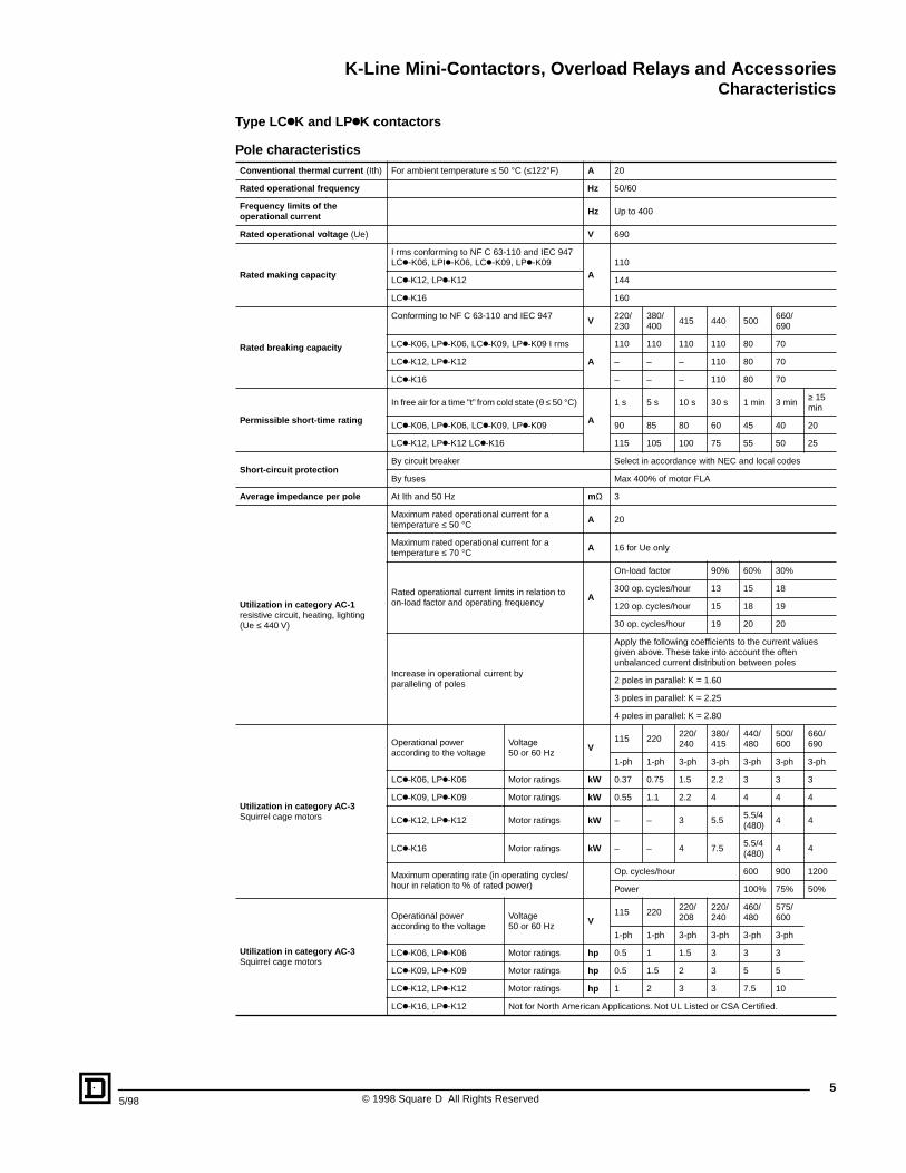
Pole characteristics
Conventional thermal current
(Ith) For ambient temperature
≤
50
°
C (
≤
122
°
F)
A
20
Rated operational frequency Hz
50/60
Frequency limits of the operational current Hz
Up to 400
Rated operational voltage
(Ue)
V
690
Rated making capacity
I rms conforming to NF C 63-110 and IEC 947 LC
k-
K06, LPI
k-
K06, LC
k-
K09, LP
k-
K09
A
110
LC
k
-K12, LP
k
-K12 144
LC
k
-K16 160
Rated breaking capacity
Conforming to NF C 63-110 and IEC 947
V
220/230
380/ 400
415 440 500660/ 690
LC
k
-K06, LP
k
-K06, LC
k
-K09, LP
k
-K09 I rms
A
110 110 110 110 80 70
LC
k
-K12, LP
k
-K12 – – – 110 80 70
LC
k
-K16 – – – 110 80 70
Permissible short-time rating
In free air for a time "t” from cold state (
θ
≤
50
°
C)
A
1 s 5 s 10 s 30 s 1 min 3 min
≥
15 min
LC
k
-K06, LP
k
-K06, LC
k
-K09, LP
k
-K09 90 85 80 60 45 40 20
LC
k
-K12, LP
k
-K12 LC
k
-K16 115 105 100 75 55 50 25
Short-circuit protection
By circuit breaker Select in accordance with NEC and local codes
By fuses Max 400% of motor FLA
Average impedance per pole
At Ith and 50 Hz
m
Ω
3
Utilization in category AC-1
resistive circuit, heating, lighting (Ue
≤
440 V)
Maximum rated operational current for a temperature
≤
50
°
C
A
20
Maximum rated operational current for a temperature
≤
70
°
C
A
16 for Ue only
Rated operational current limits in relation to on-load factor and operating frequency
A
On-load factor 90% 60% 30%
300 op. cycles/hour 13 15 18
120 op. cycles/hour 15 18 19
30 op. cycles/hour 19 20 20
Increase in operational current by paralleling of poles
Apply the following coefficients to the current values given above. These take into account the often unbalanced current distribution between poles
2 poles in parallel: K = 1.60
3 poles in parallel: K = 2.25
4 poles in parallel: K = 2.80
Utilization in category AC-3
Squirrel cage motors
Operational poweraccording to the voltage
Voltage50 or 60 Hz
V
115 220220/ 240
380/415
440/480
500/600
660/ 690
1-ph 1-ph 3-ph 3-ph 3-ph 3-ph 3-ph
LC
k
-K06, LP
k
-K06 Motor ratings
kW
0.37 0.75 1.5 2.2 3 3 3
LC
k
-K09, LP
k
-K09 Motor ratings
kW
0.55 1.1 2.2 4 4 4 4
LC
k
-K12, LP
k
-K12 Motor ratings
kW
– – 3 5.55.5/4(480)
4 4
LC
k
-K16 Motor ratings
kW
– – 4 7.55.5/4(480)
4 4
Maximum operating rate (in operating cycles/hour in relation to % of rated power)
Op. cycles/hour 600 900 1200
Power 100% 75% 50%
Utilization in category AC-3
Squirrel cage motors
Operational poweraccording to the voltage
Voltage50 or 60 Hz
V
115 220220/ 208
220/240
460/480
575/600
1-ph 1-ph 3-ph 3-ph 3-ph 3-ph
LC
k
-K06, LP
k
-K06 Motor ratings
hp
0.5 1 1.5 3 3 3
LC
k
-K09, LP
k
-K09 Motor ratings
hp
0.5 1.5 2 3 5 5
LC
k
-K12, LP
k
-K12 Motor ratings
hp
1 2 3 3 7.5 10
LC
k
-K16, LP
k
-K12 Not for North American Applications. Not UL Listed or CSA Certified.
K-Line Mini-Contactors, Overload Relays and Accessories
Characteristics
© 1998 Square D All Rights Reserved
6
5/98
Type LC
k
K and LP
k
K contactors
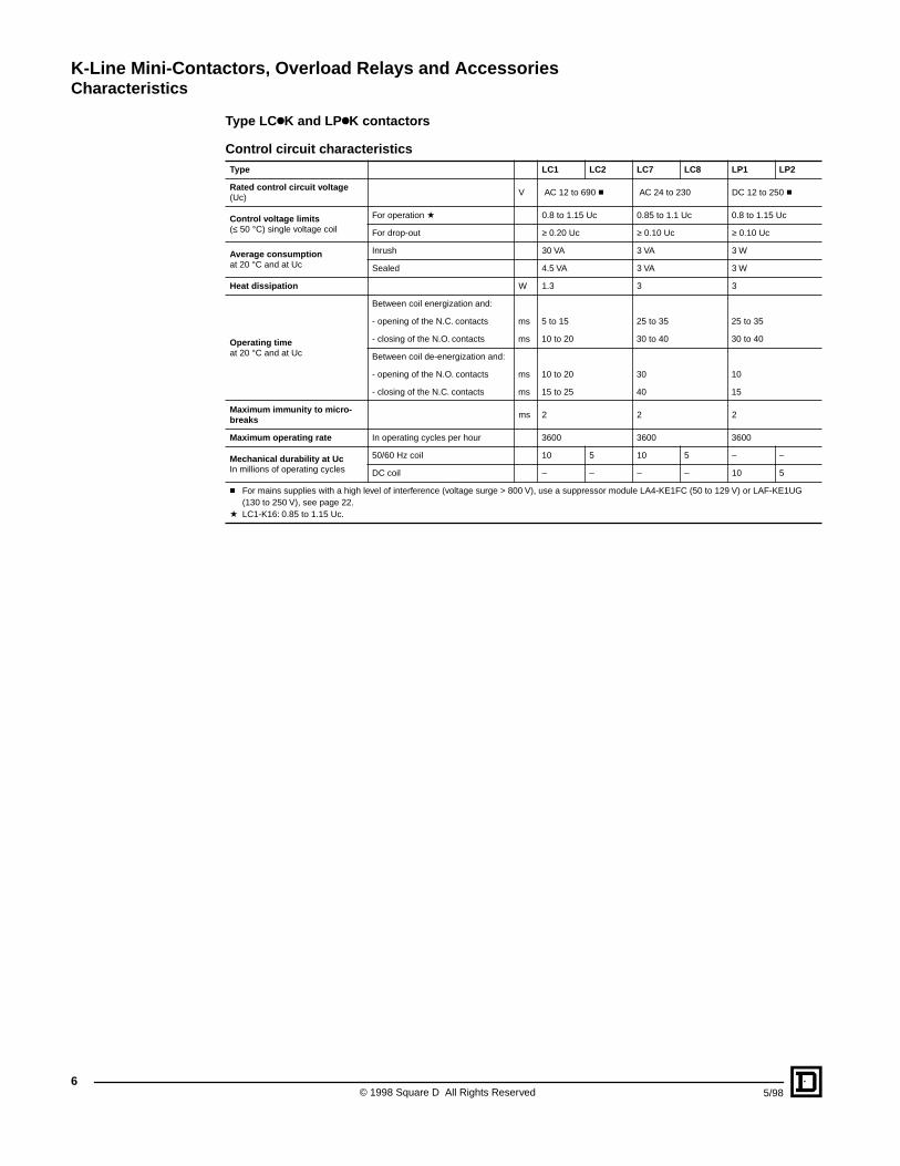
Control circuit characteristics
Type LC1 LC2 LC7 LC8 LP1 LP2
Rated control circuit voltage
(Uc)V AC 12 to 690
c
AC 24 to 230 DC 12 to 250
c
Control voltage limits
(
≤
50 °C) single voltage coil
For operation a 0.8 to 1.15 Uc 0.85 to 1.1 Uc 0.8 to 1.15 Uc
For drop-out ≥ 0.20 Uc ≥ 0.10 Uc ≥ 0.10 Uc
Average consumption at 20 °C and at Uc
Inrush 30 VA 3 VA 3 W
Sealed 4.5 VA 3 VA 3 W
Heat dissipation W 1.3 3 3
Operating time at 20 °C and at Uc
Between coil energization and:
- opening of the N.C. contacts ms 5 to 15 25 to 35 25 to 35
- closing of the N.O. contacts ms 10 to 20 30 to 40 30 to 40
Between coil de-energization and:
- opening of the N.O. contacts ms 10 to 20 30 10
- closing of the N.C. contacts ms 15 to 25 40 15
Maximum immunity to micro-breaks ms 2 2 2
Maximum operating rate In operating cycles per hour 3600 3600 3600
Mechanical durability at Uc In millions of operating cycles
50/60 Hz coil 10 5 10 5 – –
DC coil – – – – 10 5
c For mains supplies with a high level of interference (voltage surge > 800 V), use a suppressor module LA4-KE1FC (50 to 129 V) or LAF-KE1UG (130 to 250 V), see page 22.
a LC1-K16: 0.85 to 1.15 Uc.
K-Line Mini-Contactors, Overload Relays and AccessoriesCharacteristics
75/98 © 1998 Square D All Rights Reserved
Types LCkK and LPkK contactors
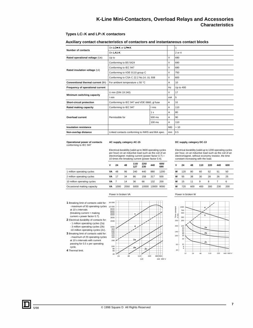
Auxiliary contact characteristics of contactors and instantaneous contact blocks
Number of contactsOn LCk-K or LPk-K 1
On LA1-K 2 or 4
Rated operational voltage (Ue) Up to V 690
Rated insulation voltage (Ui)
Conforming to BS 5424 V 690
Conforming to IEC 947 V 690
Conforming to VDE 0110 group C V 750
Conforming to CSA C 22.2 No.14, UL 508 V 600
Conventional thermal current (lth) For ambient temperature ≤ 50 °C A 10
Frequency of operational current Hz Up to 400
Minimum switching capacityU min (DIN 19 240) V 17
I min mA 5
Short-circuit protection Conforming to IEC 947 and VDE 0660, gl fuse A 10
Rated making capacity Conforming to IEC 947 I rms A 110
Overload current Permissible for
1 s A 80
500 ms A 90
100 ms A 110
Insulation resistance MΩ > 10
Non-overlap distance Linked contacts conforming to INRS and BIA spec. mm 0.5
Operational power of contactsconforming to IEC 947
AC supply, category AC-15 DC supply, category DC-13
Electrical durability (valid up to 3600 operating cycles per hour) on an inductive load such as the coil of an electromagnet: making current (power factor 0.7) = 10 times the breaking current (power factor 0.4).
Electrical durability (valid up to 1200 operating cycles per hour, on an inductive load such as the coil of an electromagnet, without economy resistor, the time constant increasing with the load.
V 24 48 110/127
220/230 440 600/
690 V 24 48 110 220 440 600
1 million operating cycles VA 48 96 240 440 880 1200 W 120 80 60 52 51 50
2 million operating cycles VA 17 34 86 158 317 500 W 55 38 30 28 26 25
10 million operating cycles VA 7 14 36 66 132 200 W 15 11 9 8 7 6
Occasional making capacity VA 1000 2050 5000 10000 13000 9000 W 720 600 400 300 230 200
1 Breaking limit of contacts valid for:- maximum of 50 operating cycles at 10 s intervals(breaking current = making current x power factor 0.7).
2 Electrical durability of contacts for:- 1 million operating cycles (2a)- 3 million operating cycles (2b)-10 million operating cycles (2c).
3 Breaking limit of contacts valid for:- maximum of 20 operating cycles at 10 s intervals with current passing for 0.5 s per operating cycle.
4 Thermal limit.
Power in broken VA Power in broken W
10 000
5000
3000
2000
1000800600500400300
200
1008060
24 48 110 220
440 690 V120
380 50040
16 000
80006000
4000
2c2b
4
1
2a
1000
700
500
300
200
1008060504030
20
1086
12 24 48 110 220 440 600 V
250
200
140
100
50
20
2c
2b
2a
3
4
Tim
e co
nsta
nt
in m
s
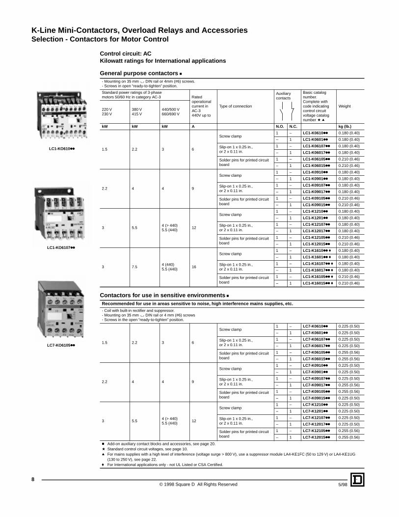
K-Line Mini-Contactors, Overload Relays and AccessoriesSelection - Contactors for Motor Control
© 1998 Square D All Rights Reserved8
5/98
Control circuit: ACKilowatt ratings for International applications
General purpose contactors c- Mounting on 35 mm " DIN rail or 4mm (#6) screws.- Screws in open “ready-to-tighten” position.
Standard power ratings of 3-phase motors 50/60 Hz in category AC-3 Rated
operational current in AC-3 440V up to
Type of connection
Auxiliary contacts
Basic catalog number.Complete with code indicating control circuit voltage catalog number a q
Weight220 V230 V
380 V415 V
440/500 V660/690 V
kW kW kW A N.O. N.C. kg (lb.)
1.5 2.2 3 6
Screw clamp1 – LC1-K0610kk 0.180 (0.40)
– 1 LC1-K0601kk 0.180 (0.40)
Slip-on 1 x 0.25 in., or 2 x 0.11 in.
1 – LC1-K06107kk 0.180 (0.40)
– 1 LC1-K06017kk 0.180 (0.40)
Solder pins for printed circuit board
1 – LC1-K06105kk 0.210 (0.46)
– 1 LC1-K06015kk 0.210 (0.46)
2.2 4 4 9
Screw clamp1 – LC1-K0910kk 0.180 (0.40)
– 1 LC1-K0901kk 0.180 (0.40)
Slip-on 1 x 0.25 in., or 2 x 0.11 in.
1 – LC1-K09107kk 0.180 (0.40)
– 1 LC1-K09017kk 0.180 (0.40)
Solder pins for printed circuit board
1 – LC1-K09105kk 0.210 (0.46)
– 1 LC1-K09015kk 0.210 (0.46)
3 5.54 (> 440)5.5 (440)
12
Screw clamp1 – LC1-K1210kk 0.180 (0.40)
– 1 LC1-K1201kk 0.180 (0.40)
Slip-on 1 x 0.25 in., or 2 x 0.11 in.
1 – LC1-K12107kk 0.180 (0.40)
– 1 LC1-K12017kk 0.180 (0.40)
Solder pins for printed circuit board
1 – LC1-K12105kk 0.210 (0.46)
– 1 LC1-K12015kk 0.210 (0.46)
3 7.54 (440)5.5 (440)
16
Screw clamp1 – LC1-K1610kk f 0.180 (0.40)
– 1 LC1-K1601kk f 0.180 (0.40)
Slip-on 1 x 0.25 in., or 2 x 0.11 in.
1 – LC1-K16107kk f 0.180 (0.40)
– 1 LC1-K16017kk f 0.180 (0.40)
Solder pins for printed circuit board
1 – LC1-K16105kk f 0.210 (0.46)
– 1 LC1-K16015kk f 0.210 (0.46)
Contactors for use in sensitive environments cRecommended for use in areas sensitive to noise, high interference mains supplies, etc.- Coil with built-in rectifier and suppressor. - Mounting on 35 mm " DIN rail or 4 mm (#6) screws- Screws in the open “ready-to-tighten” position.
1.5 2.2 3 6
Screw clamp1 – LC7-K0610kk 0.225 (0.50)
– 1 LC7-K0601kk 0.225 (0.50)
Slip-on 1 x 0.25 in., or 2 x 0.11 in.
1 – LC7-K06107kk 0.225 (0.50)
– 1 LC7-K06017kk 0.225 (0.50)
Solder pins for printed circuit board
1 – LC7-K06105kk 0.255 (0.56)
– 1 LC7-K06015kk 0.255 (0.56)
2.2 4 4 9
Screw clamp1 – LC7-K0910kk 0.225 (0.50)
– 1 LC7-K0901kk 0.225 (0.50)
Slip-on 1 x 0.25 in., or 2 x 0.11 in.
1 – LC7-K09107kk 0.225 (0.50)
– 1 LC7-K09017kk 0.255 (0.56)
Solder pins for printed circuit board
1 – LC7-K09105kk 0.255 (0.56)
– 1 LC7-K09015kk 0.225 (0.50)
3 5.54 (> 440)5.5 (440)
12
Screw clamp1 – LC7-K1210kk 0.225 (0.50)
– 1 LC7-K1201kk 0.225 (0.50)
Slip-on 1 x 0.25 in., or 2 x 0.11 in.
1 – LC7-K12107kk 0.225 (0.50)
– 1 LC7-K12017kk 0.225 (0.50)
Solder pins for printed circuit board
1 – LC7-K12105kk 0.255 (0.56)
– 1 LC7-K12015kk 0.255 (0.56)
c Add-on auxiliary contact blocks and accessories, see page 20.a Standard control circuit voltages, see page 10.q For mains supplies with a high level of interference (voltage surge > 800 V), use a suppressor module LA4-KE1FC (50 to 129 V) or LA4-KE1UG
(130 to 250 V), see page 22.f For International applications only - not UL Listed or CSA Certified.
LC1-KO610kk
LC1-KO6107kk
LC7-KO6105kk

K-Line Mini-Contactors, Overload Relays and AccessoriesSelection - Contactors for Motor Control
95/98 © 1998 Square D All Rights Reserved
Control circuit: ACHorsepower ratings for North American applications
General purpose contactors c- Mounting on 35 mm " DIN rail or 4mm (#6) screws.- Screws in open “ready-to-tighten” position.
Maximum Horsepower Rating
Maximum inductive current in AC-3 category
Type of Connection
Auxiliary contacts Basic catalog
number. Complete with code indicating control circuit voltage a q
Weight
1 - Phase50/60 Hz
3 - Phase50/60 Hz
115/120 V
230/240 V
200/208 V
220/240 V
460/480 V
575/600 V
hp hp hp hp hp hp A N.O. N.C. kg (lb.)
0.5 1 1.5 1.5 3 3 6
Screw clamp1 – LC1-K0610kk 0.180 (0.40)
– 1 LC1-K0601kk 0.180 (0.40)
Slip-on 1 x 0.25 in., or 2 x 0.11 in.
1 – LC1-K06107kk 0.180 (0.40)
– 1 LC1-K06017kk 0.180 (0.40)
Solder pins for printed circuit board
1 – LC1-K06105kk 0.210 (0.46)
– 1 LC1-K06015kk 0.210 (0.46)
0.5 1.5 2 3 5 5 9
Screw clamp1 – LC1-K0910kk 0.180 (0.40)
– 1 LC1-K0901kk 0.180 (0.40)
Slip-on 1 x 0.25 in., or 2 x 0.11 in.
1 – LC1-K09107kk 0.180 (0.40)
– 1 LC1-K09017kk 0.180 (0.40)
Solder pins for printed circuit board
1 – LC1-K09105kk 0.210 (0.46)
– 1 LC1-K09015kk 0.210 (0.46)
1 2 3 3 7.5 10 12
Screw clamp1 – LC1-K1210kk 0.180 (0.40)
– 1 LC1-K1201kk 0.180 (0.40)
Slip-on 1 x 0.25 in., or 2 x 0.11 in.
1 – LC1-K12107kk 0.180 (0.40)
– 1 LC1-K12017kk 0.180 (0.40)
Solder pins for printed circuit board
1 – LC1-K12105kk 0.210 (0.46)
– 1 LC1-K12015kk 0.210 (0.46)
Not for North American applicationsNot UL Listed or CSA Certified
Screw clamp1 – LC1-K1610kk f 0.180 (0.40)
– 1 LC1-K1601kk f 0.180 (0.40)
Slip-on 1 x 0.25 in., or 2 x 0.11 in.
1 – LC1-K16107kk f 0.180 (0.40)
– 1 LC1-K16017kk f 0.180 (0.40)
Solder pins for printed circuit board
1 – LC1-K16105kk f 0.210 (0.46)
– 1 LC1-K16015kk f 0.210 (0.46)
Contactors for use in sensitive environments cRecommended for use in areas sensitive to noise, high interference mains supplies, etc.- Coil with built-in rectifier and suppressor. - Mounting on 35 mm " DIN rail or 4mm (#6) screws- Screws in the open “ready-to-tighten” position.
0.5 1 1.5 3 3 6 6 Screw clamp 1 – LC7-K0610kk 0.225 (0.50)
– 1 LC7-K0601kk 0.225 (0.50)
Slip-on 1 x 0.25 in., or 2 x 0.11 in.
1 – LC7-K06107kk 0.225 (0.50)
– 1 LC7-K06017kk 0.225 (0.50)
Solder pins for printed circuit board
1 – LC7-K06105kk 0.255 (0.56)
– 1 LC7-K06015kk 0.255 (0.56)
0.5 1.5 2 3 5 5 9 Screw clamp 1 – LC7-K0910kk 0.225 (0.50)
– 1 LC7-K0901kk 0.225 (0.50)
Slip-on 1 x 0.25 in., or 2 x 0.11 in.
1 – LC7-K09107kk 0.225 (0.50)
– 1 LC7-K09017kk 0.255 (0.56)
Solder pins for printed circuit board
1 – LC7-K09105kk 0.255 (0.56)
– 1 LC7-K09015kk 0.225 (0.50)
1 2 3 3 7.5 10 12 Screw clamp 1 – LC7-K1210kk 0.225 (0.50)
– 1 LC7-K12101kk 0.225 (0.50)
Slip-on 1 x 0.25 in., or 2 x 0.11 in.
1 – LC7-K12107kk 0.225 (0.50)
– 1 LC7-K121017kk 0.225 (0.50)
Solder pins for printed circuit board
1 – LC7-K12005kk 0.255 (0.56)
– 1 LC7-K12015kk 0.255 (0.56)
c Add-on auxiliary contact blocks and accessories, see page 20.a Standard control circuit voltages (variable delivery times, please consult your Regional Sales Office).q For mains supplies with a high level of interference (voltage surge > 800 V), use a suppressor module LA4-KE1FC (50 to 129 V) or LA4-KE1UG
(130 to 250 V), see page 22.f For International applications only - not UL Listed or CSA Certified.
LC1-KO610kk
LC1-KO6107kk
LC7-KO6105kk
K-Line Mini-Contactors, Overload Relays and AccessoriesSelection - Contactors for Motor Control
© 1998 Square D All Rights Reserved10
5/98
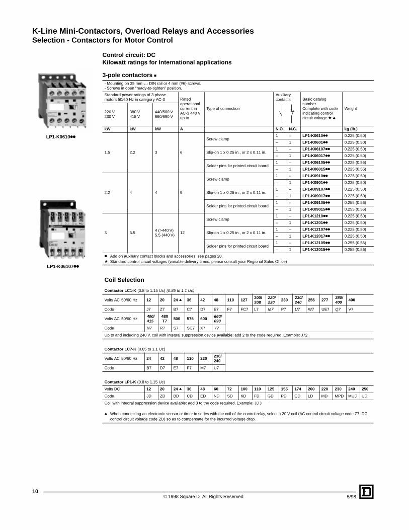
Control circuit: DCKilowatt ratings for International applications
3-pole contactors c- Mounting on 35 mm " DIN rail or 4 mm (#6) screws.- Screws in open “ready-to-tighten” position.
Standard power ratings of 3-phase motors 50/60 Hz in category AC-3 Rated
operational current in AC-3 440 V up to
Type of connection
Auxiliary contacts Basic catalog
number.Complete with code indicating control circuit voltage a q
Weight220 V230 V
380 V415 V
440/500 V660/690 V
kW kW kW A N.O. N.C. kg (lb.)
1.5 2.2 3 6
Screw clamp1 – LP1-K0610kk 0.225 (0.50)
– 1 LP1-K0601kk 0.225 (0.50)
Slip-on 1 x 0.25 in., or 2 x 0.11 in.1 – LP1-K06107kk 0.225 (0.50)
– 1 LP1-K06017kk 0.225 (0.50)
Solder pins for printed circuit board 1 – LP1-K06105kk 0.225 (0.56)
– 1 LP1-K06015kk 0.225 (0.56)
2.2 4 4 9
Screw clamp1 – LP1-K0910kk 0.225 (0.50)
– 1 LP1-K0901kk 0.225 (0.50)
Slip-on 1 x 0.25 in., or 2 x 0.11 in.1 – LP1-K09107kk 0.225 (0.50)
– 1 LP1-K09017kk 0.225 (0.50)
Solder pins for printed circuit board 1 – LP1-K09105kk 0.255 (0.56)
– 1 LP1-K09015kk 0.255 (0.56)
3 5.54 (>440 V)5.5 (440 V)
12
Screw clamp1 – LP1-K1210kk 0.225 (0.50)
– 1 LP1-K1201kk 0.225 (0.50)
Slip-on 1 x 0.25 in., or 2 x 0.11 in.1 – LP1-K12107kk 0.225 (0.50)
– 1 LP1-K12017kk 0.225 (0.50)
Solder pins for printed circuit board 1 – LP1-K12105kk 0.255 (0.56)
– 1 LP1-K12015kk 0.255 (0.56)
c Add on auxiliary contact blocks and accessories, see pages 20.a Standard control circuit voltages (variable delivery times, please consult your Regional Sales Office)
Coil Selection
Contactor LC1-K (0.8 to 1.15 Uc) (0.85 to 1.1 Uc)
Volts AC 50/60 Hz 12 20 24 q 36 42 48 110 127 200/208
220/230 230 230/
240 256 277 380/400 400
Code J7 Z7 B7 C7 D7 E7 F7 FC7 L7 M7 P7 U7 W7 UE7 Q7 V7
Volts AC 50/60 Hz400/415
480T7 500 575 600 660/
690
Code N7 R7 S7 SC7 X7 Y7
Up to and including 240 V, coil with integral suppression device available: add 2 to the code required. Example: J72
Contactor LC7-K (0.85 to 1.1 Uc)
Volts AC 50/60 Hz 24 42 48 110 220 230/240
Code B7 D7 E7 F7 M7 U7
Contactor LP1-K (0.8 to 1.15 Uc)
Volts DC 12 20 24 q 36 48 60 72 100 110 125 155 174 200 220 230 240 250
Code JD ZD BD CD ED ND SD KD FD GD PD QD LD MD MPD MUD UD
Coil with integral suppression device available: add 3 to the code required. Example: JD3
q When connecting an electronic sensor or timer in series with the coil of the control relay, select a 20 V coil (AC control circuit voltage code Z7, DC control circuit voltage code ZD) so as to compensate for the incurred voltage drop.
LP1-K0610kk
LP1-K06107kk
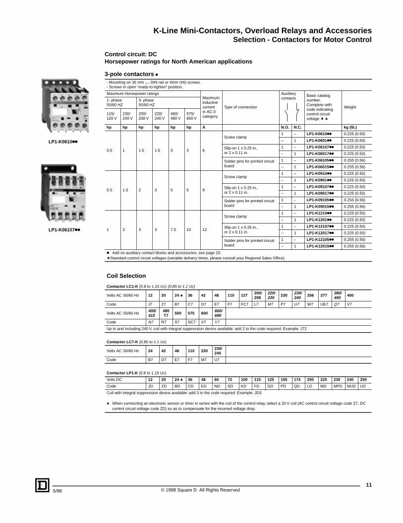
K-Line Mini-Contactors, Overload Relays and AccessoriesSelection - Contactors for Motor Control
115/98 © 1998 Square D All Rights Reserved
Control circuit: DCHorsepower ratings for North American applications
3-pole contactors c- Mounting on 35 mm " DIN rail or 4mm (#6) screws.- Screws in open “ready-to-tighten” position.
Maximum Horsepower ratings Maximuminductive current in AC-3 category
Type of connection
Auxiliary contacts
Basic catalog number.Complete with code indicating control circuit voltage a q
Weight
1- phase50/60 HZ
3- phase50/60 HZ
115/120 V
230/240 V
200/208 V
220/240 V
460/480 V
575/600 V
hp hp hp hp hp hp A N.O. N.C. kg (lb.)
0.5 1 1.5 1.5 3 3 6
Screw clamp1 – LP1-K0610kk 0.225 (0.50)
– 1 LP1-K0601kk 0.225 (0.50)
Slip-on 1 x 0.25 in.,or 2 x 0.11 in.
1 – LP1-K06107kk 0.225 (0.50)
– 1 LP1-K06017kk 0.225 (0.50)
Solder pins for printed circuit board
1 – LP1-K06105kk 0.255 (0.56)
– 1 LP1-K06015kk 0.255 (0.56)
0.5 1.5 2 3 5 5 9
Screw clamp1 – LP1-K0910kk 0.225 (0.50)
– 1 LP1-K0901kk 0.225 (0.50)
Slip-on 1 x 0.25 in.,or 2 x 0.11 in.
1 – LP1-K09107kk 0.225 (0.50)
– 1 LP1-K09017kk 0.225 (0.50)
Solder pins for printed circuit board
1 – LP1-K09105kk 0.255 (0.56)
– 1 LP1-K09015kk 0.255 (0.56)
1 2 3 3 7.5 10 12
Screw clamp1 – LP1-K1210kk 0.225 (0.50)
– 1 LP1-K1201kk 0.225 (0.50)
Slip-on 1 x 0.25 in.,or 2 x 0.11 in.
1 – LP1-K12107kk 0.225 (0.50)
– 1 LP1-K12017kk 0.225 (0.50)
Solder pins for printed circuit board
1 – LP1-K12105kk 0.255 (0.56)
– 1 LP1-K12015kk 0.255 (0.56)
c Add on auxiliary contact blocks and accessories, see page 20.aStandard control circuit voltages (variable delivery times, please consult your Regional Sales Office)
Coil Selection
Contactor LC1-K (0.8 to 1.15 Uc) (0.85 to 1.1 Uc)
Volts AC 50/60 Hz 12 20 24 q 36 42 48 110 127 200/208
220/230 230 230/
240 256 277 380/400 400
Code J7 Z7 B7 C7 D7 E7 F7 FC7 L7 M7 P7 U7 W7 UE7 Q7 V7
Volts AC 50/60 Hz400/415
480T7 500 575 600 660/
690
Code N7 R7 S7 SC7 X7 Y7
Up to and including 240 V, coil with integral suppression device available: add 2 to the code required. Example: J72
Contactor LC7-K (0.85 to 1.1 Uc)
Volts AC 50/60 Hz 24 42 48 110 220 230/240
Code B7 D7 E7 F7 M7 U7
Contactor LP1-K (0.8 to 1.15 Uc)
Volts DC 12 20 24 q 36 48 60 72 100 110 125 155 174 200 220 230 240 250
Code JD ZD BD CD ED ND SD KD FD GD PD QD LD MD MPD MUD UD
Coil with integral suppression device available: add 3 to the code required. Example: JD3
q When connecting an electronic sensor or timer in series with the coil of the control relay, select a 20 V coil (AC control circuit voltage code Z7, DC control circuit voltage code ZD) so as to compensate for the incurred voltage drop.
LP1-K0610kk
LP1-K06107kk
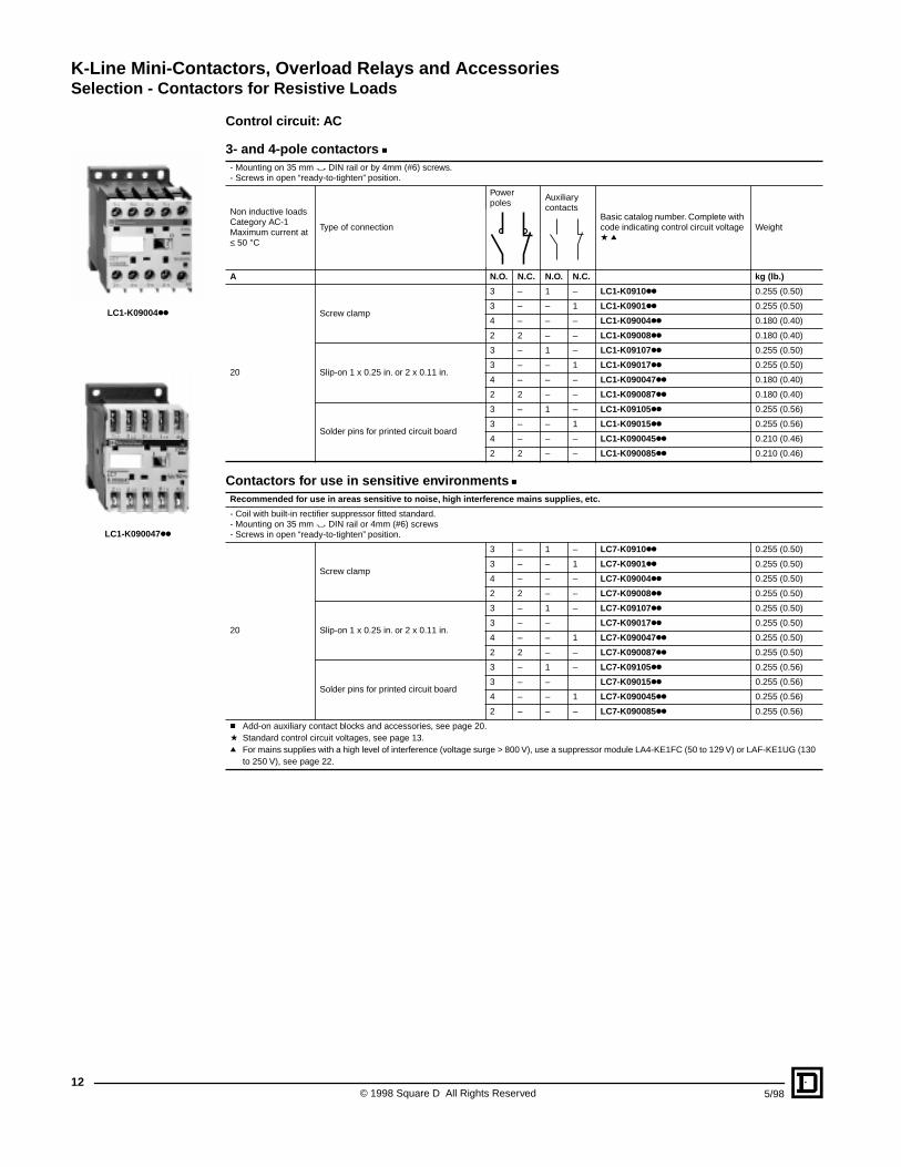
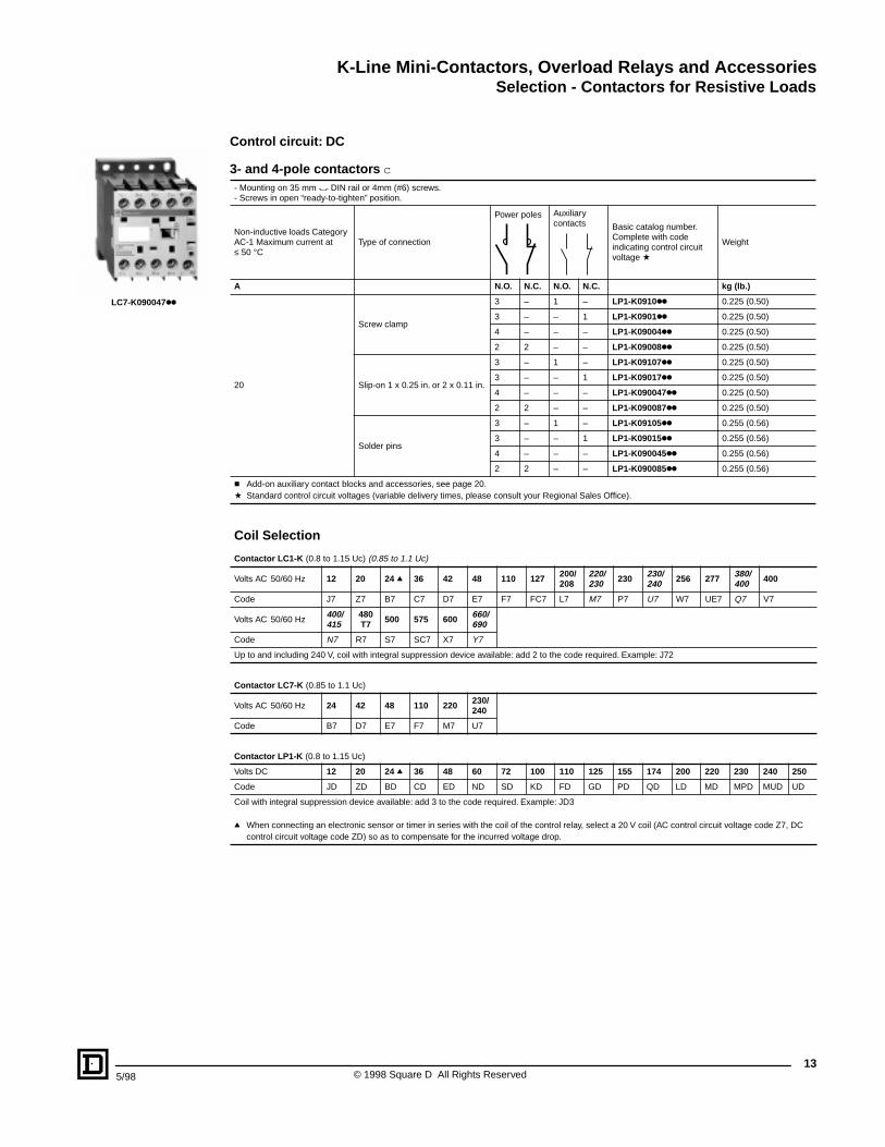
K-Line Mini-Contactors, Overload Relays and AccessoriesSelection - Contactors for Resistive Loads
© 1998 Square D All Rights Reserved12
5/98
Control circuit: AC
3- and 4-pole contactors c- Mounting on 35 mm " DIN rail or by 4mm (#6) screws.- Screws in open “ready-to-tighten” position.
Non inductive loads Category AC-1 Maximum current at ≤ 50 °C
Type of connection
Power poles
Auxiliary contacts
Basic catalog number. Complete with code indicating control circuit voltage a q
Weight
A N.O. N.C. N.O. N.C. kg (lb.)
20
Screw clamp
3 – 1 – LC1-K0910kk 0.255 (0.50)
3 – – 1 LC1-K0901kk 0.255 (0.50)
4 – – – LC1-K09004kk 0.180 (0.40)
2 2 – – LC1-K09008kk 0.180 (0.40)
Slip-on 1 x 0.25 in. or 2 x 0.11 in.
3 – 1 – LC1-K09107kk 0.255 (0.50)
3 – – 1 LC1-K09017kk 0.255 (0.50)
4 – – – LC1-K090047kk 0.180 (0.40)
2 2 – – LC1-K090087kk 0.180 (0.40)
Solder pins for printed circuit board
3 – 1 – LC1-K09105kk 0.255 (0.56)
3 – – 1 LC1-K09015kk 0.255 (0.56)
4 – – – LC1-K090045kk 0.210 (0.46)
2 2 – – LC1-K090085kk 0.210 (0.46)
Contactors for use in sensitive environments cRecommended for use in areas sensitive to noise, high interference mains supplies, etc.
- Coil with built-in rectifier suppressor fitted standard.- Mounting on 35 mm " DIN rail or 4mm (#6) screws- Screws in open “ready-to-tighten” position.
20
Screw clamp
3 – 1 – LC7-K0910kk 0.255 (0.50)
3 – – 1 LC7-K0901kk 0.255 (0.50)
4 – – – LC7-K09004kk 0.255 (0.50)
2 2 – – LC7-K09008kk 0.255 (0.50)
Slip-on 1 x 0.25 in. or 2 x 0.11 in.
3 – 1 – LC7-K09107kk 0.255 (0.50)
3 – – LC7-K09017kk 0.255 (0.50)
4 – – 1 LC7-K090047kk 0.255 (0.50)
2 2 – – LC7-K090087kk 0.255 (0.50)
Solder pins for printed circuit board
3 – 1 – LC7-K09105kk 0.255 (0.56)
3 – – LC7-K09015kk 0.255 (0.56)
4 – – 1 LC7-K090045kk 0.255 (0.56)
2 – – – LC7-K090085kk 0.255 (0.56)
c Add-on auxiliary contact blocks and accessories, see page 20.a Standard control circuit voltages, see page 13.q For mains supplies with a high level of interference (voltage surge > 800 V), use a suppressor module LA4-KE1FC (50 to 129 V) or LAF-KE1UG (130
to 250 V), see page 22.
LC1-K09004kk
LC1-K090047kk
K-Line Mini-Contactors, Overload Relays and AccessoriesSelection - Contactors for Resistive Loads
135/98 © 1998 Square D All Rights Reserved
Control circuit: DC
3- and 4-pole contactors c- Mounting on 35 mm " DIN rail or 4mm (#6) screws.- Screws in open “ready-to-tighten” position.
Non-inductive loads Category AC-1 Maximum current at ≤ 50 °C
Type of connection
Power poles Auxiliary contacts Basic catalog number.
Complete with code indicating control circuit voltage a
Weight
A N.O. N.C. N.O. N.C. kg (lb.)
20
Screw clamp
3 – 1 – LP1-K0910kk 0.225 (0.50)
3 – – 1 LP1-K0901kk 0.225 (0.50)
4 – – – LP1-K09004kk 0.225 (0.50)
2 2 – – LP1-K09008kk 0.225 (0.50)
Slip-on 1 x 0.25 in. or 2 x 0.11 in.
3 – 1 – LP1-K09107kk 0.225 (0.50)
3 – – 1 LP1-K09017kk 0.225 (0.50)
4 – – – LP1-K090047kk 0.225 (0.50)
2 2 – – LP1-K090087kk 0.225 (0.50)
Solder pins
3 – 1 – LP1-K09105kk 0.255 (0.56)
3 – – 1 LP1-K09015kk 0.255 (0.56)
4 – – – LP1-K090045kk 0.255 (0.56)
2 2 – – LP1-K090085kk 0.255 (0.56)
c Add-on auxiliary contact blocks and accessories, see page 20.a Standard control circuit voltages (variable delivery times, please consult your Regional Sales Office).
Coil Selection
Contactor LC1-K (0.8 to 1.15 Uc) (0.85 to 1.1 Uc)
Volts AC 50/60 Hz 12 20 24 q 36 42 48 110 127 200/208
220/230 230 230/
240 256 277 380/400 400
Code J7 Z7 B7 C7 D7 E7 F7 FC7 L7 M7 P7 U7 W7 UE7 Q7 V7
Volts AC 50/60 Hz400/415
480T7 500 575 600 660/
690
Code N7 R7 S7 SC7 X7 Y7
Up to and including 240 V, coil with integral suppression device available: add 2 to the code required. Example: J72
Contactor LC7-K (0.85 to 1.1 Uc)
Volts AC 50/60 Hz 24 42 48 110 220 230/240
Code B7 D7 E7 F7 M7 U7
Contactor LP1-K (0.8 to 1.15 Uc)
Volts DC 12 20 24 q 36 48 60 72 100 110 125 155 174 200 220 230 240 250
Code JD ZD BD CD ED ND SD KD FD GD PD QD LD MD MPD MUD UD
Coil with integral suppression device available: add 3 to the code required. Example: JD3
q When connecting an electronic sensor or timer in series with the coil of the control relay, select a 20 V coil (AC control circuit voltage code Z7, DC control circuit voltage code ZD) so as to compensate for the incurred voltage drop.
LC7-K090047kk
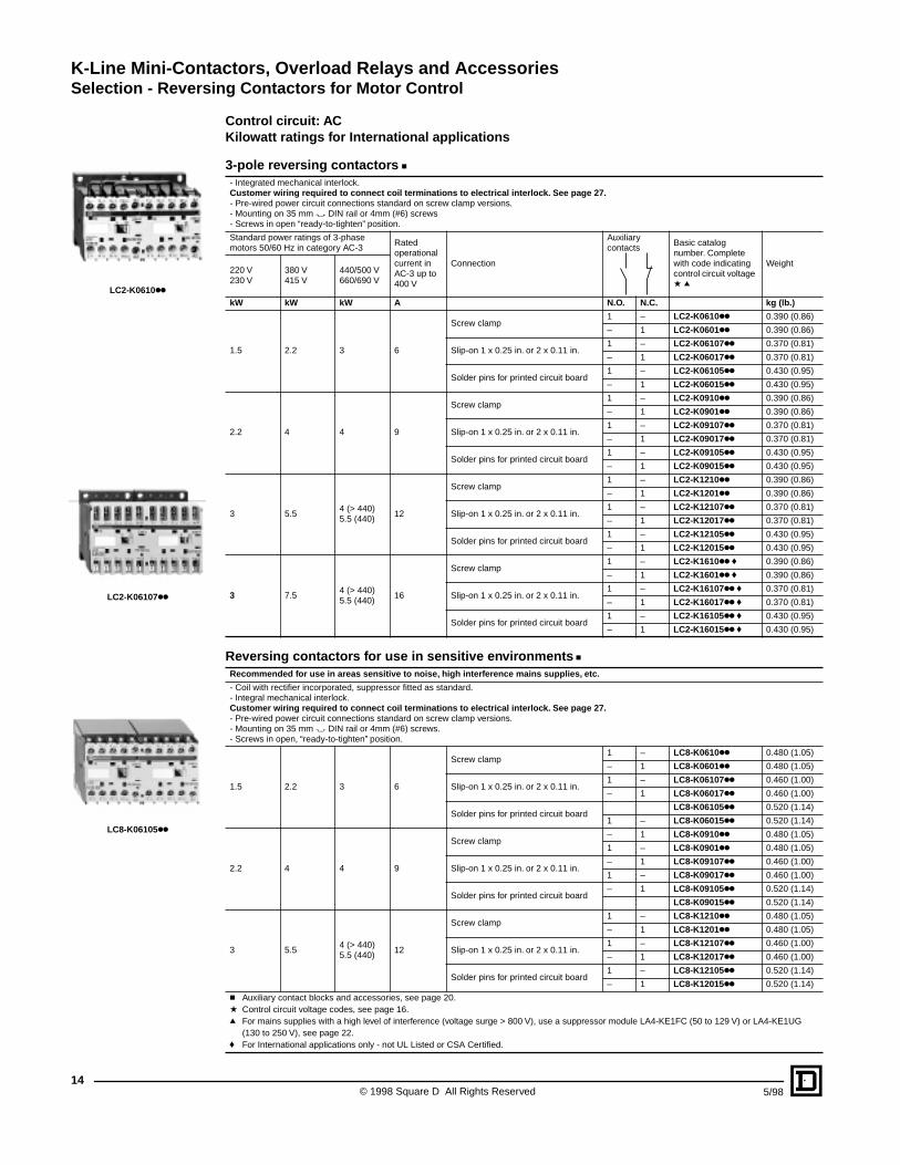
K-Line Mini-Contactors, Overload Relays and AccessoriesSelection - Reversing Contactors for Motor Control
© 1998 Square D All Rights Reserved14
5/98
Control circuit: ACKilowatt ratings for International applications
3-pole reversing contactors c- Integrated mechanical interlock.Customer wiring required to connect coil terminations to electrical interlock. See page 27.- Pre-wired power circuit connections standard on screw clamp versions.- Mounting on 35 mm " DIN rail or 4mm (#6) screws- Screws in open “ready-to-tighten” position.
Standard power ratings of 3-phase motors 50/60 Hz in category AC-3
Rated operational current in AC-3 up to 400 V
Connection
Auxiliary contacts
Basic catalog number. Complete with code indicating control circuit voltage a q
Weight220 V 230 V
380 V415 V
440/500 V660/690 V
kW kW kW A N.O. N.C. kg (lb.)
1.5 2.2 3 6
Screw clamp1 – LC2-K0610kk 0.390 (0.86)
– 1 LC2-K0601kk 0.390 (0.86)
Slip-on 1 x 0.25 in. or 2 x 0.11 in.1 – LC2-K06107kk 0.370 (0.81)
– 1 LC2-K06017kk 0.370 (0.81)
Solder pins for printed circuit board1 – LC2-K06105kk 0.430 (0.95)
– 1 LC2-K06015kk 0.430 (0.95)
2.2 4 4 9
Screw clamp1 – LC2-K0910kk 0.390 (0.86)
– 1 LC2-K0901kk 0.390 (0.86)
Slip-on 1 x 0.25 in. or 2 x 0.11 in.1 – LC2-K09107kk 0.370 (0.81)
– 1 LC2-K09017kk 0.370 (0.81)
Solder pins for printed circuit board1 – LC2-K09105kk 0.430 (0.95)
– 1 LC2-K09015kk 0.430 (0.95)
3 5.54 (> 440)5.5 (440)
12
Screw clamp1 – LC2-K1210kk 0.390 (0.86)
– 1 LC2-K1201kk 0.390 (0.86)
Slip-on 1 x 0.25 in. or 2 x 0.11 in.1 – LC2-K12107kk 0.370 (0.81)
– 1 LC2-K12017kk 0.370 (0.81)
Solder pins for printed circuit board1 – LC2-K12105kk 0.430 (0.95)
– 1 LC2-K12015kk 0.430 (0.95)
3 7.54 (> 440)5.5 (440)
16
Screw clamp1 – LC2-K1610kk f 0.390 (0.86)
– 1 LC2-K1601kk f 0.390 (0.86)
Slip-on 1 x 0.25 in. or 2 x 0.11 in.1 – LC2-K16107kk f 0.370 (0.81)
– 1 LC2-K16017kk f 0.370 (0.81)
Solder pins for printed circuit board1 – LC2-K16105kk f 0.430 (0.95)
– 1 LC2-K16015kk f 0.430 (0.95)
Reversing contactors for use in sensitive environments cRecommended for use in areas sensitive to noise, high interference mains supplies, etc.
- Coil with rectifier incorporated, suppressor fitted as standard.- Integral mechanical interlock.Customer wiring required to connect coil terminations to electrical interlock. See page 27.- Pre-wired power circuit connections standard on screw clamp versions.- Mounting on 35 mm " DIN rail or 4mm (#6) screws.- Screws in open, “ready-to-tighten” position.
1.5 2.2 3 6
Screw clamp1 – LC8-K0610kk 0.480 (1.05)
– 1 LC8-K0601kk 0.480 (1.05)
Slip-on 1 x 0.25 in. or 2 x 0.11 in.1 – LC8-K06107kk 0.460 (1.00)
– 1 LC8-K06017kk 0.460 (1.00)
Solder pins for printed circuit boardLC8-K06105kk 0.520 (1.14)
1 – LC8-K06015kk 0.520 (1.14)
2.2 4 4 9
Screw clamp– 1 LC8-K0910kk 0.480 (1.05)
1 – LC8-K0901kk 0.480 (1.05)
Slip-on 1 x 0.25 in. or 2 x 0.11 in.– 1 LC8-K09107kk 0.460 (1.00)
1 – LC8-K09017kk 0.460 (1.00)
Solder pins for printed circuit board– 1 LC8-K09105kk 0.520 (1.14)
LC8-K09015kk 0.520 (1.14)
3 5.54 (> 440)5.5 (440)
12
Screw clamp1 – LC8-K1210kk 0.480 (1.05)
– 1 LC8-K1201kk 0.480 (1.05)
Slip-on 1 x 0.25 in. or 2 x 0.11 in.1 – LC8-K12107kk 0.460 (1.00)
– 1 LC8-K12017kk 0.460 (1.00)
Solder pins for printed circuit board1 – LC8-K12105kk 0.520 (1.14)
– 1 LC8-K12015kk 0.520 (1.14)
c Auxiliary contact blocks and accessories, see page 20.a Control circuit voltage codes, see page 16.q For mains supplies with a high level of interference (voltage surge > 800 V), use a suppressor module LA4-KE1FC (50 to 129 V) or LA4-KE1UG
(130 to 250 V), see page 22.f For International applications only - not UL Listed or CSA Certified.
LC2-K0610kk
LC2-K06107kk
LC8-K06105kk
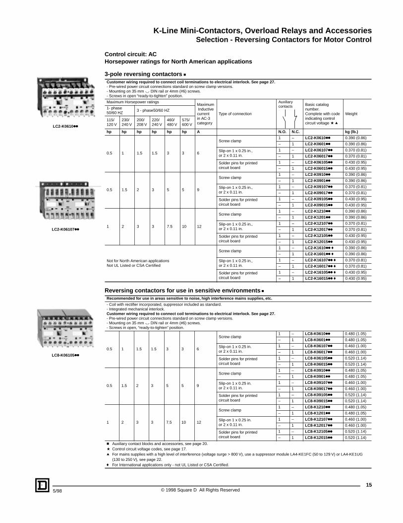
K-Line Mini-Contactors, Overload Relays and AccessoriesSelection - Reversing Contactors for Motor Control
155/98 © 1998 Square D All Rights Reserved
Control circuit: ACHorsepower ratings for North American applications
3-pole reversing contactors cCustomer wiring required to connect coil terminations to electrical interlock. See page 27.- Pre-wired power circuit connections standard on screw clamp versions.- Mounting on 35 mm " DIN rail or 4mm (#6) screws.- Screws in open “ready-to-tighten” position.
Maximum Horsepower ratings Maximum Inductive current in AC-3 category
Type of connection
Auxiliary contacts Basic catalog
number.Complete with code indicating control circuit voltage a q
Weight1- phase50/60 HZ
3 - phase50/60 HZ
115/120 V
230/240 V
200/208 V
220/240 V
460/480 V
575/600 V
hp hp hp hp hp hp A N.O. N.C. kg (lb.)
0.5 1 1.5 1.5 3 3 6
Screw clamp1 – LC2-K0610kk 0.390 (0.86)
– 1 LC2-K0601kk 0.390 (0.86)
Slip-on 1 x 0.25 in., or 2 x 0.11 in.
1 – LC2-K06107kk 0.370 (0.81)
– 1 LC2-K06017kk 0.370 (0.81)
Solder pins for printed circuit board
1 – LC2-K06105kk 0.430 (0.95)
– 1 LC2-K06015kk 0.430 (0.95)
0.5 1.5 2 3 5 5 9
Screw clamp1 – LC2-K0910kk 0.390 (0.86)
– 1 LC2-K0901kk 0.390 (0.86)
Slip-on 1 x 0.25 in., or 2 x 0.11 in.
1 – LC2-K09107kk 0.370 (0.81)
– 1 LC2-K09017kk 0.370 (0.81)
Solder pins for printed circuit board
1 – LC2-K09105kk 0.430 (0.95)
– 1 LC2-K09015kk 0.430 (0.95)
1 2 3 3 7.5 10 12
Screw clamp1 – LC2-K1210kk 0.390 (0.86)
– 1 LC2-K1201kk 0.390 (0.86)
Slip-on 1 x 0.25 in., or 2 x 0.11 in.
1 – LC2-K12107kk 0.370 (0.81)
– 1 LC2-K12017kk 0.370 (0.81)
Solder pins for printed circuit board
1 – LC2-K12105kk 0.430 (0.95)
– 1 LC2-K12015kk 0.430 (0.95)
Not for North American applicationsNot UL Listed or CSA Certified
Screw clamp1 – LC2-K1610kk f 0.390 (0.86)
– 1 LC2-K1601kk f 0.390 (0.86)
Slip-on 1 x 0.25 in., or 2 x 0.11 in.
1 – LC2-K16107kk f 0.370 (0.81)
– 1 LC2-K16017kk f 0.370 (0.81)
Solder pins for printed circuit board
1 – LC2-K16105kk f 0.430 (0.95)
– 1 LC2-K16015kk f 0.430 (0.95)
Reversing contactors for use in sensitive environments cRecommended for use in areas sensitive to noise, high interference mains supplies, etc.
- Coil with rectifier incorporated, suppressor included as standard.- Integrated mechanical interlock.Customer wiring required to connect coil terminations to electrical interlock. See page 27.- Pre-wired power circuit connections standard on screw clamp versions.- Mounting on 35 mm " DIN rail or 4mm (#6) screws.- Screws in open, “ready-to-tighten” position.
0.5 1 1.5 1.5 3 3 6
Screw clamp1 – LC8-K0610kk 0.480 (1.05)
– 1 LC8-K0601kk 0.480 (1.05)
Slip-on 1 x 0.25 in. or 2 x 0.11 in.
1 – LC8-K06107kk 0.460 (1.00)
– 1 LC8-K06017kk 0.460 (1.00)
Solder pins for printed circuit board
1 – LC8-K06105kk 0.520 (1.14)
– 1 LC8-K06015kk 0.520 (1.14)
0.5 1.5 2 3 5 5 9
Screw clamp1 – LC8-K0910kk 0.480 (1.05)
– 1 LC8-K0901kk 0.480 (1.05)
Slip-on 1 x 0.25 in. or 2 x 0.11 in.
1 – LC8-K09107kk 0.460 (1.00)
– 1 LC8-K09017kk 0.460 (1.00)
Solder pins for printed circuit board
1 – LC8-K09105kk 0.520 (1.14)
– 1 LC8-K09015kk 0.520 (1.14)
1 2 3 3 7.5 10 12
Screw clamp1 – LC8-K1210kk 0.480 (1.05)
– 1 LC8-K1201kk 0.480 (1.05)
Slip-on 1 x 0.25 in. or 2 x 0.11 in.
1 – LC8-K12107kk 0.460 (1.00)
– 1 LC8-K12017kk 0.460 (1.00)
Solder pins for printed circuit board
1 – LC8-K12105kk 0.520 (1.14)
– 1 LC8-K12015kk 0.520 (1.14)
c Auxiliary contact blocks and accessories, see page 20.a Control circuit voltage codes, see page 17.q For mains supplies with a high level of interference (voltage surge > 800 V), use a suppressor module LA4-KE1FC (50 to 129 V) or LA4-KE1UG
(130 to 250 V), see page 22.f For International applications only - not UL Listed or CSA Certified.
LC8-K06105kk
LC2-K06107kk
LC2-K0610kk
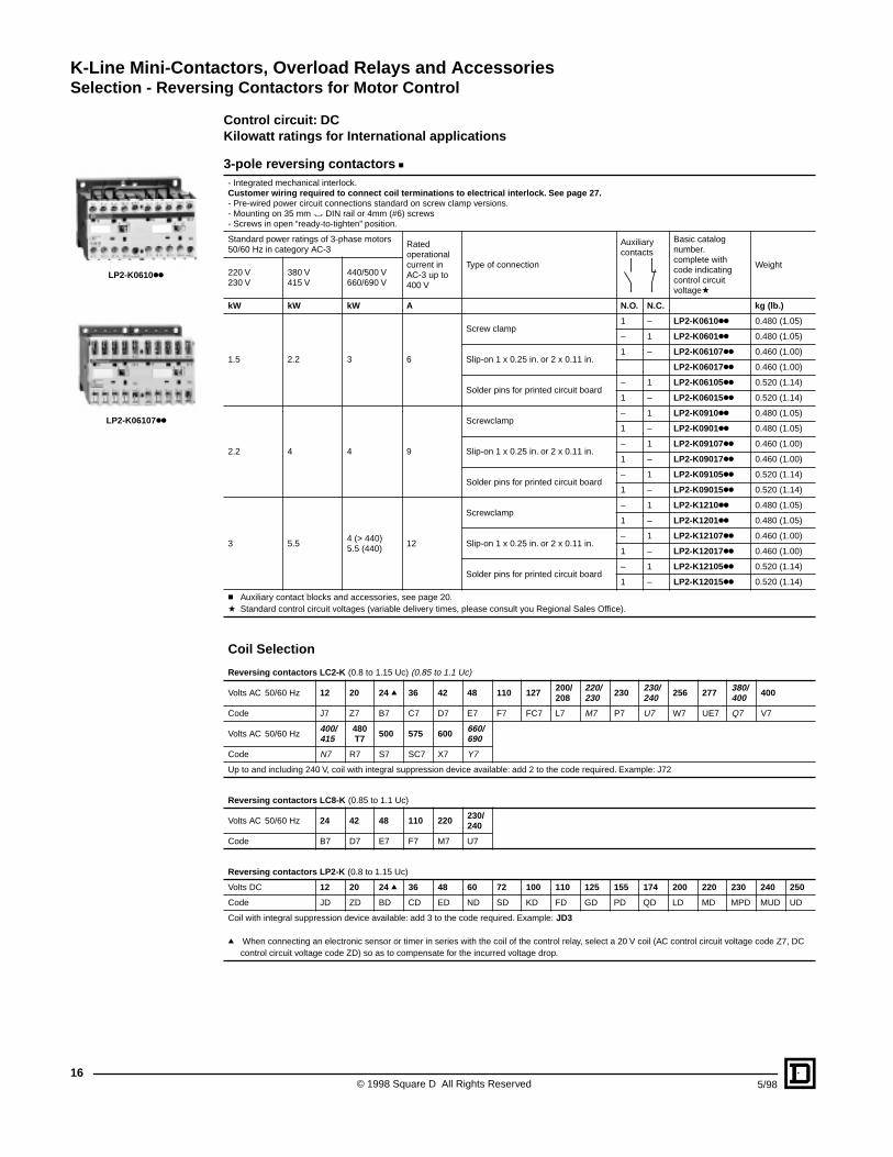
K-Line Mini-Contactors, Overload Relays and AccessoriesSelection - Reversing Contactors for Motor Control
© 1998 Square D All Rights Reserved16
5/98
Control circuit: DCKilowatt ratings for International applications
3-pole reversing contactors c- Integrated mechanical interlock.Customer wiring required to connect coil terminations to electrical interlock. See page 27.- Pre-wired power circuit connections standard on screw clamp versions.- Mounting on 35 mm " DIN rail or 4mm (#6) screws- Screws in open “ready-to-tighten” position.
Standard power ratings of 3-phase motors 50/60 Hz in category AC-3
Rated operational current in AC-3 up to 400 V
Type of connection
Auxiliary contacts
Basic catalog number.complete with code indicating control circuit voltagea
Weight220 V230 V
380 V 415 V
440/500 V660/690 V
kW kW kW A N.O. N.C. kg (lb.)
1.5 2.2 3 6
Screw clamp1 – LP2-K0610kk 0.480 (1.05)
– 1 LP2-K0601kk 0.480 (1.05)
Slip-on 1 x 0.25 in. or 2 x 0.11 in.1 – LP2-K06107kk 0.460 (1.00)
LP2-K06017kk 0.460 (1.00)
Solder pins for printed circuit board– 1 LP2-K06105kk 0.520 (1.14)
1 – LP2-K06015kk 0.520 (1.14)
2.2 4 4 9
Screwclamp– 1 LP2-K0910kk 0.480 (1.05)
1 – LP2-K0901kk 0.480 (1.05)
Slip-on 1 x 0.25 in. or 2 x 0.11 in.– 1 LP2-K09107kk 0.460 (1.00)
1 – LP2-K09017kk 0.460 (1.00)
Solder pins for printed circuit board– 1 LP2-K09105kk 0.520 (1.14)
1 – LP2-K09015kk 0.520 (1.14)
3 5.54 (> 440)5.5 (440)
12
Screwclamp– 1 LP2-K1210kk 0.480 (1.05)
1 – LP2-K1201kk 0.480 (1.05)
Slip-on 1 x 0.25 in. or 2 x 0.11 in.– 1 LP2-K12107kk 0.460 (1.00)
1 – LP2-K12017kk 0.460 (1.00)
Solder pins for printed circuit board– 1 LP2-K12105kk 0.520 (1.14)
1 – LP2-K12015kk 0.520 (1.14)
c Auxiliary contact blocks and accessories, see page 20.a Standard control circuit voltages (variable delivery times, please consult you Regional Sales Office).
Coil Selection
Reversing contactors LC2-K (0.8 to 1.15 Uc) (0.85 to 1.1 Uc)
Volts AC 50/60 Hz 12 20 24 q 36 42 48 110 127 200/208
220/230 230 230/
240 256 277 380/400 400
Code J7 Z7 B7 C7 D7 E7 F7 FC7 L7 M7 P7 U7 W7 UE7 Q7 V7
Volts AC 50/60 Hz400/415
480T7 500 575 600 660/
690
Code N7 R7 S7 SC7 X7 Y7
Up to and including 240 V, coil with integral suppression device available: add 2 to the code required. Example: J72
Reversing contactors LC8-K (0.85 to 1.1 Uc)
Volts AC 50/60 Hz 24 42 48 110 220 230/240
Code B7 D7 E7 F7 M7 U7
Reversing contactors LP2-K (0.8 to 1.15 Uc)
Volts DC 12 20 24 q 36 48 60 72 100 110 125 155 174 200 220 230 240 250
Code JD ZD BD CD ED ND SD KD FD GD PD QD LD MD MPD MUD UD
Coil with integral suppression device available: add 3 to the code required. Example: JD3
q When connecting an electronic sensor or timer in series with the coil of the control relay, select a 20 V coil (AC control circuit voltage code Z7, DC control circuit voltage code ZD) so as to compensate for the incurred voltage drop.
LP2-K0610kk
LP2-K06107kk
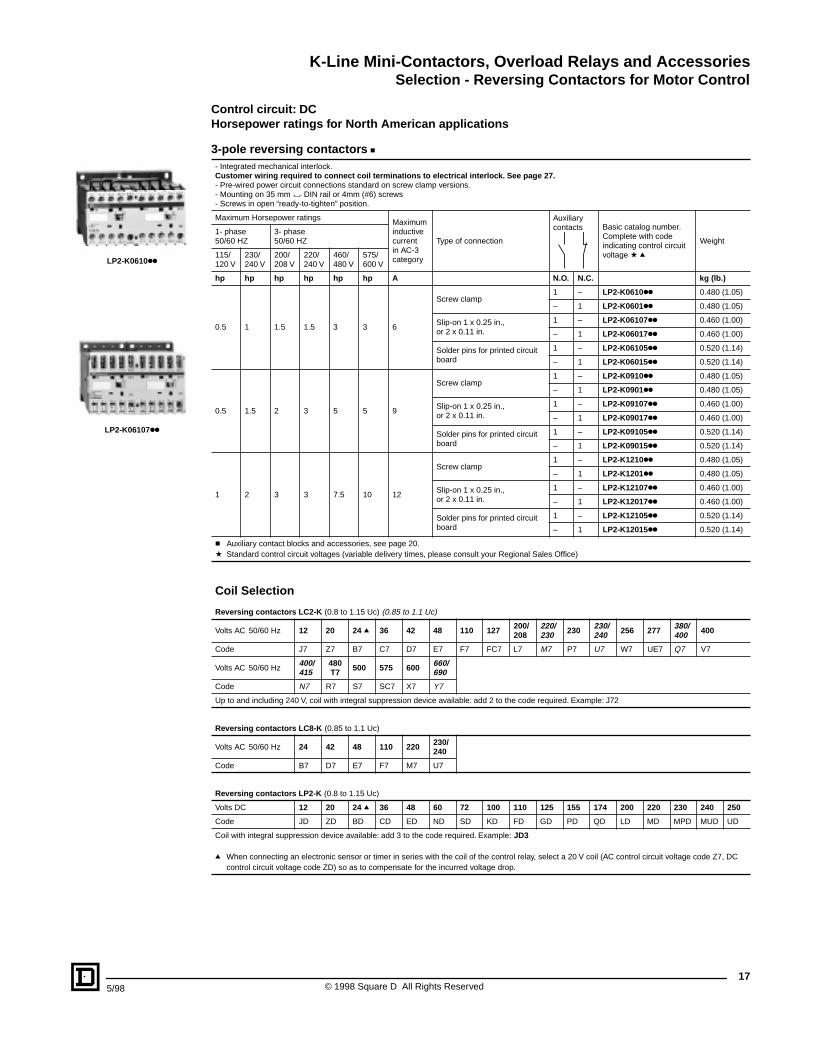
K-Line Mini-Contactors, Overload Relays and AccessoriesSelection - Reversing Contactors for Motor Control
175/98 © 1998 Square D All Rights Reserved
Control circuit: DCHorsepower ratings for North American applications
3-pole reversing contactors c- Integrated mechanical interlock.Customer wiring required to connect coil terminations to electrical interlock. See page 27.- Pre-wired power circuit connections standard on screw clamp versions.- Mounting on 35 mm " DIN rail or 4mm (#6) screws- Screws in open “ready-to-tighten” position.
Maximum Horsepower ratings Maximuminductive current in AC-3 category
Type of connection
Auxiliary contacts Basic catalog number.
Complete with code indicating control circuit voltage a q
Weight1- phase50/60 HZ
3- phase50/60 HZ
115/120 V
230/240 V
200/208 V
220/240 V
460/480 V
575/600 V
hp hp hp hp hp hp A N.O. N.C. kg (lb.)
0.5 1 1.5 1.5 3 3 6
Screw clamp1 – LP2-K0610kk 0.480 (1.05)
– 1 LP2-K0601kk 0.480 (1.05)
Slip-on 1 x 0.25 in.,or 2 x 0.11 in.
1 – LP2-K06107kk 0.460 (1.00)
– 1 LP2-K06017kk 0.460 (1.00)
Solder pins for printed circuit board
1 – LP2-K06105kk 0.520 (1.14)
– 1 LP2-K06015kk 0.520 (1.14)
0.5 1.5 2 3 5 5 9
Screw clamp1 – LP2-K0910kk 0.480 (1.05)
– 1 LP2-K0901kk 0.480 (1.05)
Slip-on 1 x 0.25 in.,or 2 x 0.11 in.
1 – LP2-K09107kk 0.460 (1.00)
– 1 LP2-K09017kk 0.460 (1.00)
Solder pins for printed circuit board
1 – LP2-K09105kk 0.520 (1.14)
– 1 LP2-K09015kk 0.520 (1.14)
1 2 3 3 7.5 10 12
Screw clamp1 – LP2-K1210kk 0.480 (1.05)
– 1 LP2-K1201kk 0.480 (1.05)
Slip-on 1 x 0.25 in.,or 2 x 0.11 in.
1 – LP2-K12107kk 0.460 (1.00)
– 1 LP2-K12017kk 0.460 (1.00)
Solder pins for printed circuit board
1 – LP2-K12105kk 0.520 (1.14)
– 1 LP2-K12015kk 0.520 (1.14)
c Auxiliary contact blocks and accessories, see page 20.a Standard control circuit voltages (variable delivery times, please consult your Regional Sales Office)
Coil Selection
Reversing contactors LC2-K (0.8 to 1.15 Uc) (0.85 to 1.1 Uc)
Volts AC 50/60 Hz 12 20 24 q 36 42 48 110 127 200/208
220/230 230 230/
240 256 277 380/400 400
Code J7 Z7 B7 C7 D7 E7 F7 FC7 L7 M7 P7 U7 W7 UE7 Q7 V7
Volts AC 50/60 Hz400/415
480T7 500 575 600 660/
690
Code N7 R7 S7 SC7 X7 Y7
Up to and including 240 V, coil with integral suppression device available: add 2 to the code required. Example: J72
Reversing contactors LC8-K (0.85 to 1.1 Uc)
Volts AC 50/60 Hz 24 42 48 110 220 230/240
Code B7 D7 E7 F7 M7 U7
Reversing contactors LP2-K (0.8 to 1.15 Uc)
Volts DC 12 20 24 q 36 48 60 72 100 110 125 155 174 200 220 230 240 250
Code JD ZD BD CD ED ND SD KD FD GD PD QD LD MD MPD MUD UD
Coil with integral suppression device available: add 3 to the code required. Example: JD3
q When connecting an electronic sensor or timer in series with the coil of the control relay, select a 20 V coil (AC control circuit voltage code Z7, DC control circuit voltage code ZD) so as to compensate for the incurred voltage drop.
LP2-K0610kk
LP2-K06107kk

K-Line Mini-Contactors, Overload Relays and AccessoriesSelection - Reversing Contactors for Resistive Loads
© 1998 Square D All Rights Reserved18
5/98
Control circuit: AC
3 and 4-pole reversing contactors c- Integrated mechanical interlock.Customer wiring required to connect coil terminations to electrical interlock. See page 27.- Pre-wired power circuit connections standard on screw clamp versions.- Mounting on 35 mm " DIN rail or 4mm (#6) screws.- Screws in open “ready-to-tighten” position.
Non inductive loads Category AC-1 Maximum current at ≤ 50 °C
Type of connection
Power poles Auxiliary contacts Basic catalog number. Complete
with code indicating control circuit voltage a q
Weight
A N.O. N.C. N.O. N.C. kg. (lb.)
20
Screw clamp
3 – 1 – LC2-K0910kk f 0.390 (0.86)
3 – – 1 LC2-K0901kk f 0.390 (0.86)
4 – – – LC2-K09004kk 0.380 (0.84)
Slip-on 1 x 0.25 in. or 2 x 0.11 in.
3 – – 1 LC2-K09107kk 0.370 (0.81)
3 – 1 – LC2-K09017kk 0.370 (0.81)
4 – – – LC2-K090047kk 0.370 (0.81)
Solder pins for circuit board
3 – 1 1 LC2-K09105kk 0.430 (0.95)
3 – – – LC2-K09015kk 0.430 (0.95)
4 – – – LC2-K090045kk 0.430 (0.95)
Reversing contactors for use in sensitive environments cRecommended for use in areas sensitive to noise, high interference mains supplies, etc.
- Coil with rectifier incorporated, suppressor included as standard.- Integrated mechanical interlock.Customer wiring required to connect coil terminations to electrical interlock. See page 27.- Mounting on 35 mm " DIN rail or 4mm (#6) screws.- Screws in open, “ready-to-tighten” position.
20
Screw clamp
3 – 1 – LC8-K0910kk f 0.480 (1.05)
3 – – 1 LC8-K0901kk f 0.480 (1.05)
4 – – – LC8-K09004kk 0.470 (1.03)
Slip-on 1 x 0.25 in. or 2 x 0.11 in.
3 – – 1 LC8-K09107kk 0.460 (1.01)
3 – 1 – LC8-K09017kk 0.460 (1.01)
4 – – – LC8-K090047kk 0.460 (1.01)
Solder pins for circuit board
3 – 1 1 LC8-K09105kk 0.520 (1.14)
3 – – – LC8-K09015kk 0.520 (1.14)
4 – – – LC8-K090045kk 0.520 (1.14)
c Auxiliary contact blocks and accessories, see page 20.a Control circuit voltage codes, see opposite page 19.q For mains supplies with a high level of interference (voltage surge > 800 V), use a suppressor module LA4-KE1FC (50 to 129 V) or
LAF-KE1UG (130 to 250 V), see page 22.f Warning: this reversing contactor is pre-wired for reverse motor operation as standard.
Coil Selection
Reversing contactors LC2-K (0.8 to 1.15 Uc) (0.85 to 1.1 Uc)
Volts AC 50/60 Hz 12 20 24 q 36 42 48 110 127 200/208
220/230 230 230/
240 256 277 380/400 400
Code J7 Z7 B7 C7 D7 E7 F7 FC7 L7 M7 P7 U7 W7 UE7 Q7 V7
Volts AC 50/60 Hz400/415
480T7 500 575 600 660/
690
Code N7 R7 S7 SC7 X7 Y7
Up to and including 240 V, coil with integral suppression device available: add 2 to the code required. Example: J72
Reversing contactors LC8-K (0.85 to 1.1 Uc)
Volts AC 50/60 Hz 24 42 48 110 220 230/240
Code B7 D7 E7 F7 M7 U7
Reversing contactors LP2-K (0.85 to 1.1 Uc)
Volts DC 12 20 24 f 36 48 60 72 100 110 125 155 174 200 220 230 240 250
Code JD ZD BD CD ED ND SD KD FD GD PD QD LD MD MPD MUD UD
Coil with integral suppression device available: add 3 to the code required. Example: JD3
q Warning: this reversing contactor is pre-wired for reverse motor operation as standard.f When connecting an electronic sensor or timer in series with the coil of the control relay, select a 20 V coil (AC control circuit voltage code Z7, DC
control circuit voltage code ZD) so as to compensate for the incurred voltage drop
LC2-K090045kk
LC8-K09105kk
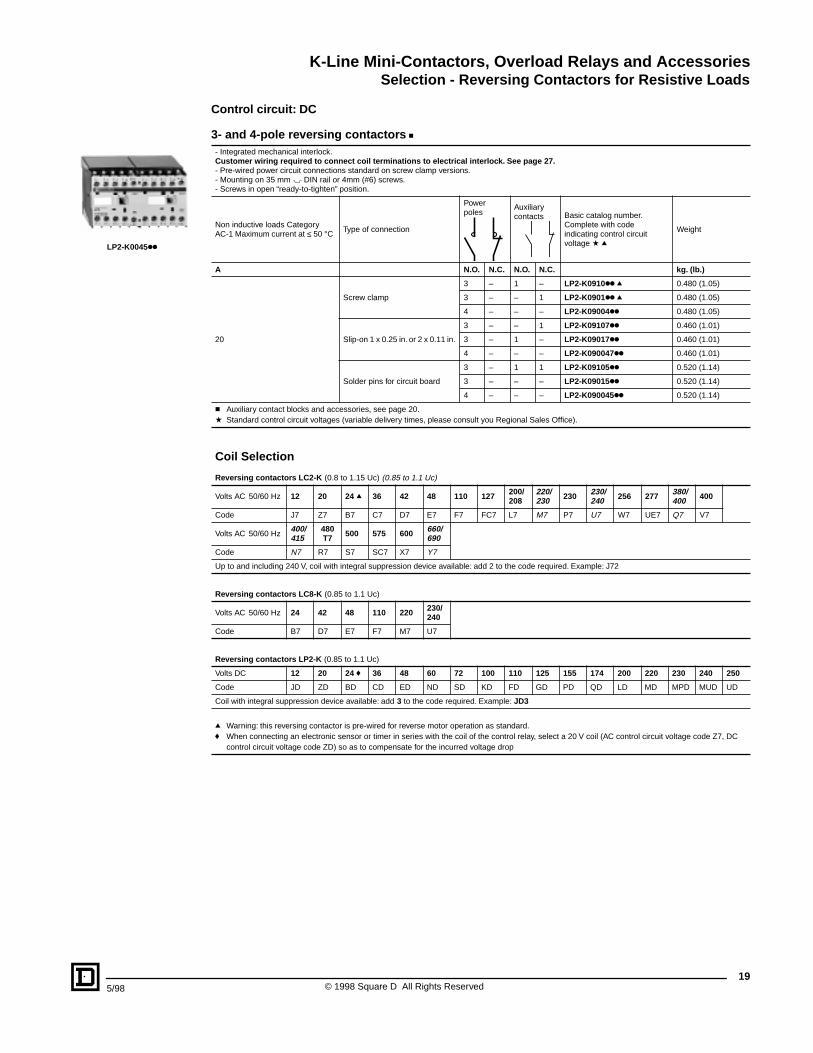
K-Line Mini-Contactors, Overload Relays and AccessoriesSelection - Reversing Contactors for Resistive Loads
195/98 © 1998 Square D All Rights Reserved
Control circuit: DC
3- and 4-pole reversing contactors c- Integrated mechanical interlock.Customer wiring required to connect coil terminations to electrical interlock. See page 27.- Pre-wired power circuit connections standard on screw clamp versions.- Mounting on 35 mm " DIN rail or 4mm (#6) screws.- Screws in open “ready-to-tighten” position.
Non inductive loads Category AC-1 Maximum current at ≤ 50 °C
Type of connection
Power poles
Auxiliary contacts Basic catalog number.
Complete with code indicating control circuit voltage a q
Weight
A N.O. N.C. N.O. N.C. kg. (lb.)
20
Screw clamp
3 – 1 – LP2-K0910kk q 0.480 (1.05)
3 – – 1 LP2-K0901kk q 0.480 (1.05)
4 – – – LP2-K09004kk 0.480 (1.05)
Slip-on 1 x 0.25 in. or 2 x 0.11 in.
3 – – 1 LP2-K09107kk 0.460 (1.01)
3 – 1 – LP2-K09017kk 0.460 (1.01)
4 – – – LP2-K090047kk 0.460 (1.01)
Solder pins for circuit board
3 – 1 1 LP2-K09105kk 0.520 (1.14)
3 – – – LP2-K09015kk 0.520 (1.14)
4 – – – LP2-K090045kk 0.520 (1.14)
c Auxiliary contact blocks and accessories, see page 20.a Standard control circuit voltages (variable delivery times, please consult you Regional Sales Office).
Coil Selection
Reversing contactors LC2-K (0.8 to 1.15 Uc) (0.85 to 1.1 Uc)
Volts AC 50/60 Hz 12 20 24 q 36 42 48 110 127 200/208
220/230 230 230/
240 256 277 380/400 400
Code J7 Z7 B7 C7 D7 E7 F7 FC7 L7 M7 P7 U7 W7 UE7 Q7 V7
Volts AC 50/60 Hz400/415
480T7 500 575 600 660/
690
Code N7 R7 S7 SC7 X7 Y7
Up to and including 240 V, coil with integral suppression device available: add 2 to the code required. Example: J72
Reversing contactors LC8-K (0.85 to 1.1 Uc)
Volts AC 50/60 Hz 24 42 48 110 220 230/240
Code B7 D7 E7 F7 M7 U7
Reversing contactors LP2-K (0.85 to 1.1 Uc)
Volts DC 12 20 24 f 36 48 60 72 100 110 125 155 174 200 220 230 240 250
Code JD ZD BD CD ED ND SD KD FD GD PD QD LD MD MPD MUD UD
Coil with integral suppression device available: add 3 to the code required. Example: JD3
q Warning: this reversing contactor is pre-wired for reverse motor operation as standard.f When connecting an electronic sensor or timer in series with the coil of the control relay, select a 20 V coil (AC control circuit voltage code Z7, DC
control circuit voltage code ZD) so as to compensate for the incurred voltage drop
LP2-K0045kk
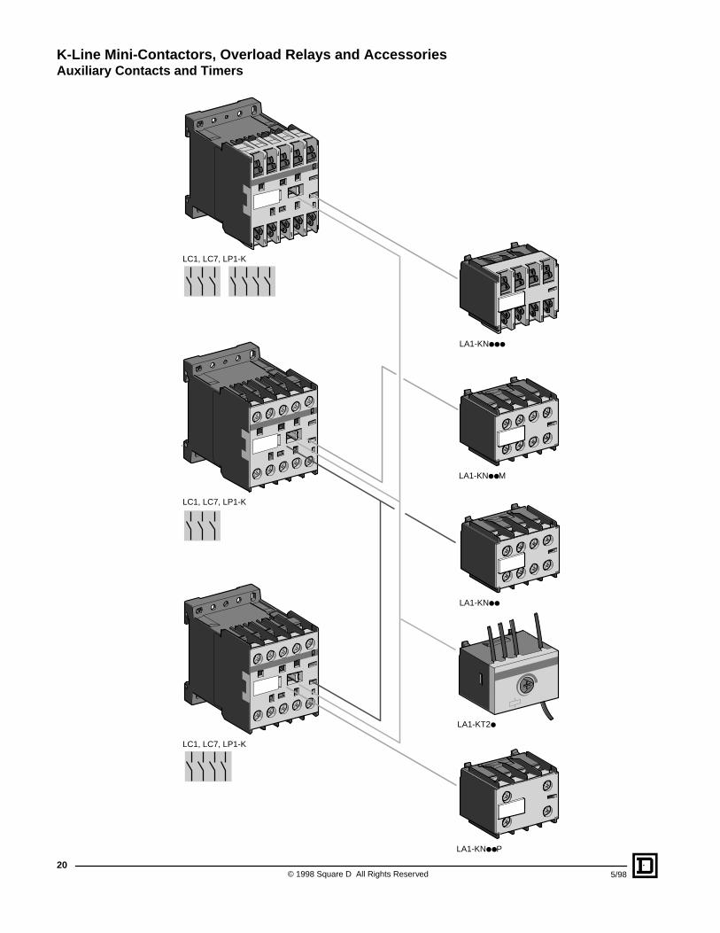
K-Line Mini-Contactors, Overload Relays and AccessoriesAuxiliary Contacts and Timers
© 1998 Square D All Rights Reserved20
5/98
LC1, LC7, LP1-K
LC1, LC7, LP1-K
LA1-KNP
LC1, LC7, LP1-K
LA1-KNM
LA1-KN
LA1-KN
LA1-KT2
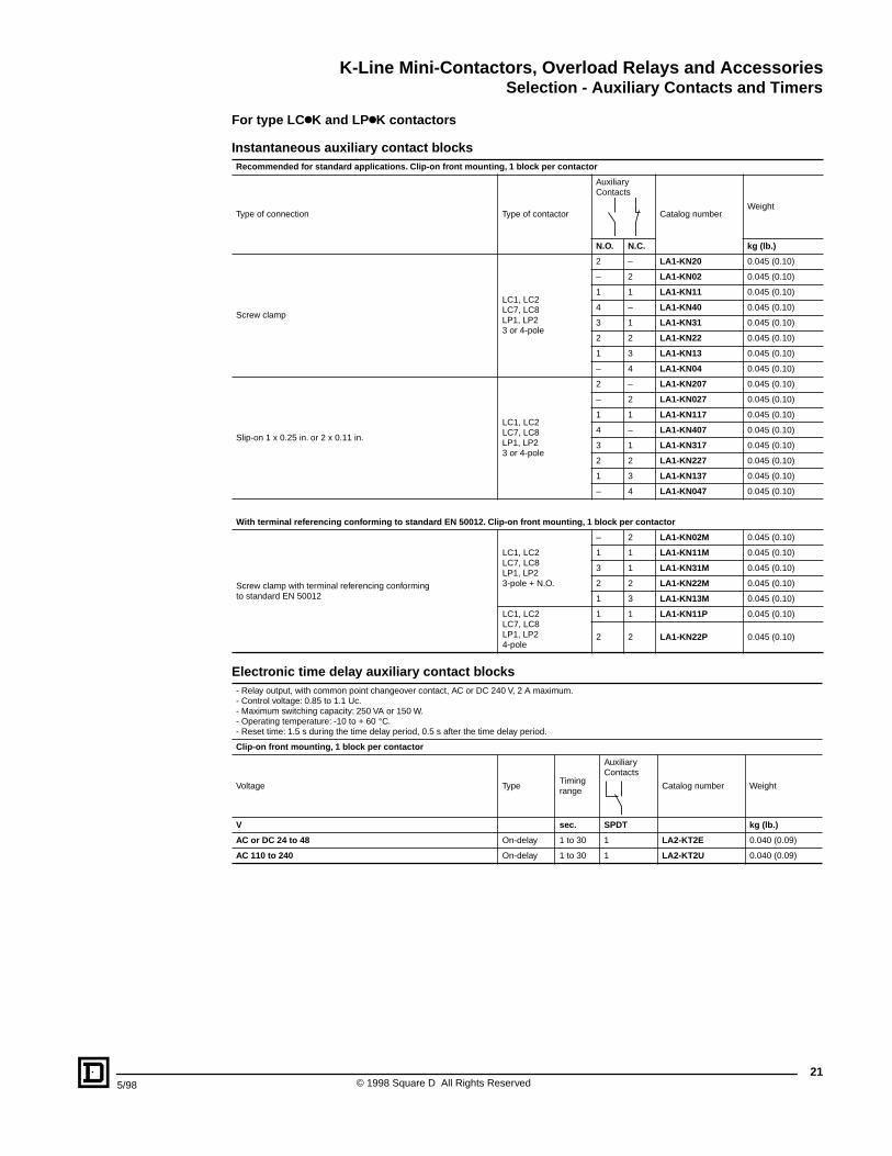
K-Line Mini-Contactors, Overload Relays and AccessoriesSelection - Auxiliary Contacts and Timers
215/98 © 1998 Square D All Rights Reserved
For type LCkK and LPkK contactors
Instantaneous auxiliary contact blocksRecommended for standard applications. Clip-on front mounting, 1 block per contactor
Type of connection Type of contactor
Auxiliary Contacts
Catalog number Weight
N.O. N.C. kg (lb.)
Screw clamp
LC1, LC2LC7, LC8LP1, LP23 or 4-pole
2 – LA1-KN20 0.045 (0.10)
– 2 LA1-KN02 0.045 (0.10)
1 1 LA1-KN11 0.045 (0.10)
4 – LA1-KN40 0.045 (0.10)
3 1 LA1-KN31 0.045 (0.10)
2 2 LA1-KN22 0.045 (0.10)
1 3 LA1-KN13 0.045 (0.10)
– 4 LA1-KN04 0.045 (0.10)
Slip-on 1 x 0.25 in. or 2 x 0.11 in.
LC1, LC2LC7, LC8LP1, LP23 or 4-pole
2 – LA1-KN207 0.045 (0.10)
– 2 LA1-KN027 0.045 (0.10)
1 1 LA1-KN117 0.045 (0.10)
4 – LA1-KN407 0.045 (0.10)
3 1 LA1-KN317 0.045 (0.10)
2 2 LA1-KN227 0.045 (0.10)
1 3 LA1-KN137 0.045 (0.10)
– 4 LA1-KN047 0.045 (0.10)
With terminal referencing conforming to standard EN 50012. Clip-on front mounting, 1 block per contactor
Screw clamp with terminal referencing conforming to standard EN 50012
LC1, LC2LC7, LC8LP1, LP23-pole + N.O.
– 2 LA1-KN02M 0.045 (0.10)
1 1 LA1-KN11M 0.045 (0.10)
3 1 LA1-KN31M 0.045 (0.10)
2 2 LA1-KN22M 0.045 (0.10)
1 3 LA1-KN13M 0.045 (0.10)
LC1, LC2LC7, LC8LP1, LP24-pole
1 1 LA1-KN11P 0.045 (0.10)
2 2 LA1-KN22P 0.045 (0.10)
Electronic time delay auxiliary contact blocks- Relay output, with common point changeover contact, AC or DC 240 V, 2 A maximum.- Control voltage: 0.85 to 1.1 Uc.- Maximum switching capacity: 250 VA or 150 W.- Operating temperature: -10 to + 60 °C.- Reset time: 1.5 s during the time delay period, 0.5 s after the time delay period.
Clip-on front mounting, 1 block per contactor
Voltage Type Timingrange
Auxiliary Contacts
Catalog number Weight
V sec. SPDT kg (lb.)
AC or DC 24 to 48 On-delay 1 to 30 1 LA2-KT2E 0.040 (0.09)
AC 110 to 240 On-delay 1 to 30 1 LA2-KT2U 0.040 (0.09)
K-Line Mini-Contactors, Overload Relays and AccessoriesSelection - Accessories
© 1998 Square D All Rights Reserved22
5/98
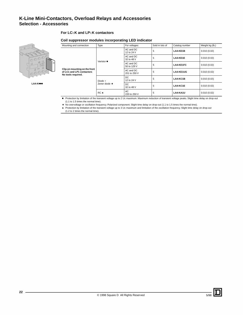
For LCkK and LPkK contactors
Coil suppressor modules incorporating LED indicatorMounting and connection Type For voltages: Sold in lots of Catalog number Weight kg (lb.)
Clip-on mounting on the front of LC1 and LP1 contactorsNo tools required.
Varistor c
AC and DC12 to 24 V
5 LA4-KE1B 0.010 (0.02)
AC and DC32 to 48 V
5 LA4-KE1E 0.010 (0.02)
AC and DC50 to 129 V
5 LA4-KE1FC 0.010 (0.02)
AC and DC201 to 250 V
5 LA4-KE1UG 0.010 (0.02)
Diode +Zener diode a
DC12 to 24 V
5 LA4-KC1B 0.010 (0.02)
DC32 to 48 V
5 LA4-KC1E 0.010 (0.02)
RC qAC220 to 250 V
5 LA4-KA1U 0.010 (0.02)
c Protection by limitation of the transient voltage up to 2 Uc maximum. Maximum reduction of transient voltage peaks. Slight time delay on drop-out (1.1 to 1.5 times the normal time).
a No overvoltage or oscillation frequency. Polarized component. Slight time delay on drop-out (1.1 to 1.5 times the normal time).q Protection by limitation of the transient voltage up to 3 Uc maximum and limitation of the oscillation frequency. Slight time delay on drop-out
(1.2 to 2 times the normal time).
LA4-Kkkk
K-Line Mini-Contactors, Overload Relays and AccessoriesSelection - Accessories
235/98 © 1998 Square D All Rights Reserved
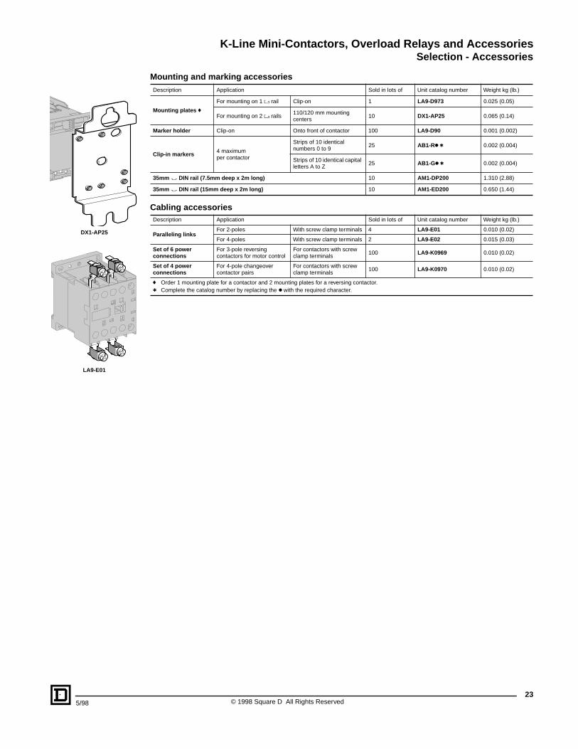
Mounting and marking accessoriesDescription Application Sold in lots of Unit catalog number Weight kg (lb.)
Mounting plates f
For mounting on 1 ' rail Clip-on 1 LA9-D973 0.025 (0.05)
For mounting on 2 ' rails110/120 mm mounting centers
10 DX1-AP25 0.065 (0.14)
Marker holder Clip-on Onto front of contactor 100 LA9-D90 0.001 (0.002)
Clip-in markers 4 maximumper contactor
Strips of 10 identical numbers 0 to 9
25 AB1-Rk t 0.002 (0.004)
Strips of 10 identical capital letters A to Z
25 AB1-Gk t 0.002 (0.004)
35mm " DIN rail (7.5mm deep x 2m long) 10 AM1-DP200 1.310 (2.88)
35mm " DIN rail (15mm deep x 2m long) 10 AM1-ED200 0.650 (1.44)
Cabling accessoriesDescription Application Sold in lots of Unit catalog number Weight kg (lb.)
Paralleling linksFor 2-poles With screw clamp terminals 4 LA9-E01 0.010 (0.02)
For 4-poles With screw clamp terminals 2 LA9-E02 0.015 (0.03)
Set of 6 power connections
For 3-pole reversing contactors for motor control
For contactors with screw clamp terminals
100 LA9-K0969 0.010 (0.02)
Set of 4 power connections
For 4-pole changeover contactor pairs
For contactors with screw clamp terminals
100 LA9-K0970 0.010 (0.02)
f Order 1 mounting plate for a contactor and 2 mounting plates for a reversing contactor.t Complete the catalog number by replacing the k with the required character.
LA9-E01
DX1-AP25
K-Line Mini-Contactors, Overload Relays and AccessoriesDimensions and Mounting
© 1998 Square D All Rights Reserved24
5/98
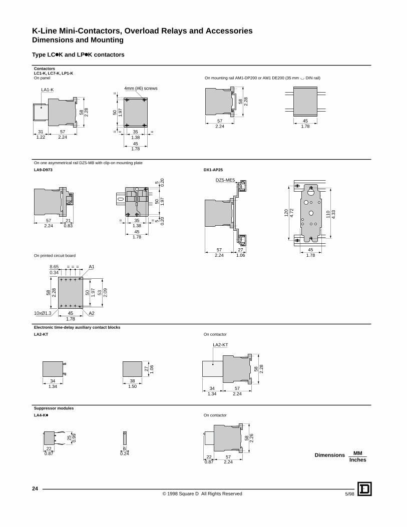
Type LCkK and LPkK contactors
Contactors LC1-K, LC7-K, LP1-K On panel On mounting rail AM1-DP200 or AM1 DE200 (35 mm " DIN rail)
On one asymmetrical rail DZ5-MB with clip-on mounting plate
LA9-D973 DX1-AP25
On printed circuit board
Electronic time-delay auxiliary contact blocks
LA2-KT On contactor
Suppressor modules
LA4-Kk On contactor
57312.241.22
LA1-K
58 2.28 50 1.97
==
351.3845
1.78
= =
4mm (#6) screws
57
58 2.28
452.24 1.78
45
35
1.78
1.38= =
505
51.
970.
200.
20572.24
210.83
110
4.33
451.78
120
4.72
572.24
271.06
DZ5-ME5
50 1.97 53 2.09
451.78
58 2.28
8.650.34
= = =
10xØ1.3
A1
A2
1.343834
1.50
27 1.06
57342.241.34
LA2-KT
58 2.28
60.24
25 0.99
220.87
572.24
220.87
58 2.26
MMInches
Dimensions
K-Line Mini-Contactors, Overload Relays and AccessoriesDimensions and Mounting
255/98 © 1998 Square D All Rights Reserved
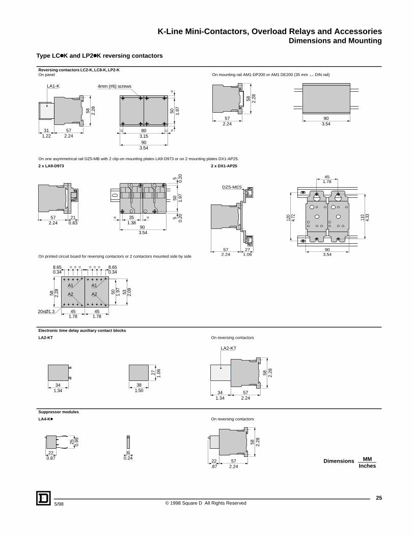
Type LCkK and LP2kK reversing contactors
Reversing contactors LC2-K, LC8-K, LP2-K On panel On mounting rail AM1-DP200 or AM1 DE200 (35 mm " DIN rail)
On one asymmetrical rail DZ5-MB with 2 clip-on mounting plates LA9-D973 or on 2 mounting plates DX1-AP25.
2 x LA9-D973 2 x DX1-AP25
On printed circuit board for reversing contactors or 2 contactors mounted side by side
Electronic time delay auxiliary contact blocks
LA2-KT On reversing contactors
Suppressor modules
LA4-Kk On reversing contactors
572.24
311.22
LA1-K58 2.28 50 1.97
==
903.54
803.15
4mm (#6) screws
==
57
58 2.28
902.24 3.54
90
35= =
505
51.
970.
200.
2057 21
3.54
1.382.24 0.83
57 272.24 1.06
DZ5-ME5
903.54
110
120
4.33
4.72
451.78
45
58
8.65 = = =
20xØ1.3
A1
A2 50
45
8.65
1.78
0.34
1.78
0.34===
53
2.28 1.97
2.09
A1
A2
1.343834
1.50
27 1.06
57342.241.34
LA2-KT
58 2.28
6
25 0.99
220.240.87
57222.24.87
58 2.28
MMInches
Dimensions

K-Line Mini-Contactors, Overload Relays and AccessoriesSchematics
© 1998 Square D All Rights Reserved26
5/98
Type LCkK and LP2kK contactors and accessories
3-pole contactorsLC1-K, LC7-K, LP1-K
Integrated coil suppression deviceLC7-K
3 P + N.O. 3 P + N.C.
4-pole contactorsLC1-K, LC7-K, LP1-K
Integrated coil suppression device LC7-K
4 P 2 P N.O. + P N.C.
Instantaneous auxiliary contacts LA1-KFor contactors LCk-K and LPk-K
2 N.O. LA1-KN20LA1-KN207
2 N.C. LA1-KN02LA1-KN027
1 N.O. + 1 N.C.LA1-KN11LA1-KN117
4 N.O. LA1-KN40LA1-KN407
3 N.O. + 1 N.C. LA1-KN31LA1-KN317
2 N.O. + 2 N.C. LA1-KN22LA1-KN227
1 N.O. + 3 N.C. LA1-KN13LA1-KN137
4 N.C.LA1-KN04LA1-KN047
Terminal referencing conforming to standard EN 50012For 3-pole contactors
2 N.C. LA1-KN02M
1 N.O. + 1 N.C.LA1-KN11M
3 N.O. + 1 N.C. LA1-KN31M
2 N.O. + 2 N.C. LA1-KN22M
1 N.O. + 3 N.C.LA1-KN13M
For 4-pole contactors
1 N.O. + 1 N.C.LA1-KN11P
2 N.O. + 2 N.C.LA1-KN22P
Electronic time delay auxiliary contact blocksLA2-KTFor contactors LCk-K and LPk-K1 C/O
Suppressor modulesLA4-KC LA4-KE
A1
A2
13/N
O14
A1
A2
1/L1
T1/
2
3/L2
T2/
4
5/L3
T3/
6 2221
/NC
A1
A2
1/L1
T1/
2
3/L2
T2/
4
5/L3
T3/
6
A1
A2
A1
A2
1/L1
T1/
2
3/L2
T2/
4
5/L3
T3/
6
7/L4
T4/
8
R1
R2
A1
A2
12
34
R3
R4
53/N
O54
63/N
O64
61/N
C62
51/N
C52
61/N
C62
53/N
O54
54 64 74
53/N
O
63/N
O
73/N
O
83/N
O84
53/N
O54
61/N
C62
73/N
O74
83/N
O84
53/N
O54
61/N
C62
71/N
C72
83/N
O84 54 62 72 82
53/N
O
61/N
C
71/N
C
81/N
C
51/N
C52
61/N
C62
71/N
C72
81/N
C82
31/N
C32
21/N
C22 22 34
21/N
C
33/N
O
33/N
O34
21/N
C22
43/N
O44
53/N
O54
21/N
C22
43/N
O44
53/N
O54
31/N
C32
21/N
C22
53/N
O54
31/N
C32
41/N
C42
21/N
C22
13/N
O14 22
13/N
O14
21/N
C
31/N
C32
43/N
O44
A1
A2
1815
16
+ –DC AC/ DC
K-Line Mini-Contactors, Overload Relays and AccessoriesSchematics
275/98 © 1998 Square D All Rights Reserved
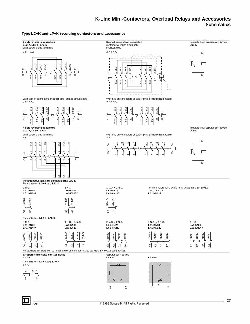
Type LCkK and LPkK reversing contactors and accessories
3-pole reversing contactorsLC2-K, LC8-K, LP2-KWith screw clamp terminals
Dashed lines indicate suggested customer wiring to electrically interlock coils
Integrated coil suppression deviceLC8-K
3 P + N.O. 3 P + N.C.
With Slip-on connectors or solder pins (printed circuit board)3 P+ N.O.
With Slip-on connectors or solder pins (printed circuit board)3 P + N.C.
4-pole reversing contactors LC2-K, LC8-K, LP2-K
Integrated coil suppression deviceLC8-K
With screw clamp terminals4 P
With Slip-on connectors or solder pins (printed circuit board)4 P
Instantaneous auxiliary contact blocks LA1-KFor contactors LCk-K and LP2-K
2 N.O. LA1-KN20LA1-KN207
2 N.C. LA1-KN02LA1-KN027
1 N.O. + 1 N.C.LA1-KN11LA1-KN117
Terminal referencing conforming to standard EN 500121 N.O. + 1 N.C.LA1-KN11P
For contactors LCk-K, LP2-K
4 N.O. LA1-KN40LA1-KN407
3 N.O. + 1 N.C. LA1-KN31LA1-KN317
2 N.O. + 2 N.C. LA1-KN22LA1-KN227
1 N.O. + 3 N.C. LA1-KN13LA1-KN137
4 N.C.LA1-KN04LA1-KN047
For auxiliary contacts with terminal referencing conforming to standard EN 50012 see page 21.
Electronic time delay contact blocksLA2-KT
Suppressor modulesLA4-KC LA4-KE
For contactors LCk-K and LPk-K1 C/O
A1
A2
13/N
O14
A1
A2
1/L1
T1/
2
3/L2
T2/
4
5/L3
T3/
6
13/N
O14
A1
A2
1/L1
T1/
2
3/L2
T2/
4
5/L3
T3/
6
21/N
C22
A1
A2
1/L
1T
1/2
3/L
2T
2/4
5/L
3T
3/6
21/N
C22
A1
A2
1/L
1T
1/2
3/L
2T
2/4
5/L
3T
3/6
13/N
O14
A1
A2
1/L1
T1/
2
3/L2
T2/
4
5/L3
T3/
6
13/N
O14
A1
A2
1/L1
T1/
2
3/L2
T2/
4
5/L3
T3/
6
21/N
C22
A1
A2
1/L1
T1/
2
3/L2
T2/
4
5/L3
T3/
6
21/N
C22
A1
A2
1/L1
T1/
2
3/L2
T2/
4
5/L3
T3/
6
A1
A2
A1
A2
12
34
56
A1
A2
12
34
56
1/L1
1/L2
1/L3
2/L1
2/L2
2/L3
L1 L2 L3
78
1N
78
2NN
A1
A2
12
34
56
A1
A2
12
34
78
78
56
53/N
O54
63/N
O64
61/N
C62
51/N
C52
61/N
C62
53/N
O54
54 64 74
53/N
O
63/N
O
73/N
O
83/N
O84 62 74
53/N
O54
61/N
C
73/N
O
83/N
O84
53/N
O54
61/N
C62
71/N
C72
83/N
O84 54 62 72 82
53/N
O
61/N
C
71/N
C
81/N
C
51/N
C52
61/N
C62
71/N
C72
81/N
C82
+ –DC AC/ DC
A1
A2
1815
16
K-Line Mini-Contactors, Overload Relays and AccessoriesCharacteristics
© 1998 Square D All Rights Reserved28
5/98
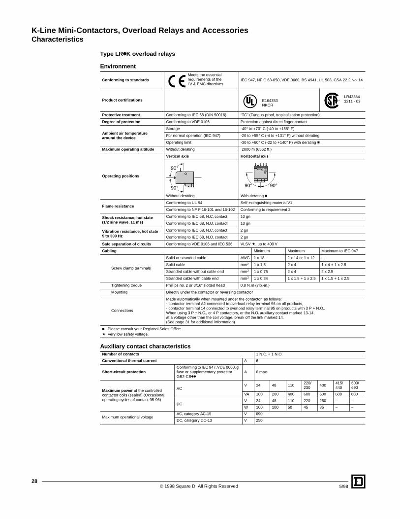
Type LRkK overload relays
Environment
Conforming to standardsMeets the essential requirements of the LV & EMC directives
IEC 947, NF C 63-650, VDE 0660, BS 4941, UL 508, CSA 22.2 No. 14
Product certifications E164353 NKCR
LR43364 3211 - 03
Protective treatment Conforming to IEC 68 (DIN 50016) “TC” (Fungus-proof, tropicalization protection)
Degree of protection Conforming to VDE 0106 Protection against direct finger contact
Ambient air temperature around the device
Storage -40° to +70° C (-40 to +158° F)
For normal operation (IEC 947) -20 to +55° C (-4 to +131° F) without derating
Operating limit -30 to +60° C (-22 to +140° F) with derating c
Maximum operating altitude Without derating 2000 m (6562 ft.)
Operating positions
Vertical axis Horizontal axis
Without derating With derating c
Flame resistanceConforming to UL 94 Self-extinguishing material V1
Conforming to NF F 16-101 and 16-102 Conforming to requirement 2
Shock resistance, hot state (1/2 sine wave, 11 ms)
Conforming to IEC 68, N.C. contact 10 gn
Conforming to IEC 68, N.O. contact 10 gn
Vibration resistance, hot state5 to 300 Hz
Conforming to IEC 68, N.C. contact 2 gn
Conforming to IEC 68, N.O. contact 2 gn
Safe separation of circuits Conforming to VDE 0106 and IEC 536 VLSV a, up to 400 V
Cabling Minimum Maximum Maximum to IEC 947
Screw clamp terminals
Solid or stranded cable AWG 1 x 18 2 x 14 or 1 x 12 –
Solid cable mm2 1 x 1.5 2 x 4 1 x 4 + 1 x 2.5
Stranded cable without cable end mm2 1 x 0.75 2 x 4 2 x 2.5
Stranded cable with cable end mm2 1 x 0.34 1 x 1.5 + 1 x 2.5 1 x 1.5 + 1 x 2.5
Tightening torque Phillips no. 2 or 3/16” slotted head 0.8 N.m (7lb.-in.)
Mounting Directly under the contactor or reversing contactor
Connections
Made automatically when mounted under the contactor, as follows:- contactor terminal A2 connected to overload relay terminal 96 on all products,- contactor terminal 14 connected to overload relay terminal 95 on products with 3 P + N.O.. When using 3 P + N.C., or 4 P contactors, or the N.O. auxiliary contact marked 13-14,at a voltage other than the coil voltage, break off the link marked 14. (See page 31 for additional information)
c Please consult your Regional Sales Office.a Very low safety voltage.
Auxiliary contact characteristicsNumber of contacts 1 N.C. + 1 N.O.
Conventional thermal current A 6
Short-circuit protectionConforming to IEC 947, VDE 0660. gl fuse or supplementary protector GB2-CBkk
A 6 max.
Maximum power of the controlled contactor coils (sealed) (Occasional operating cycles of contact 95-96)
AC V 24 48 110
220/230
400 415/440
600/690
VA 100 200 400 600 600 600 600
DCV 24 48 110 220 250 – –
W 100 100 50 45 35 – –
Maximum operational voltageAC, category AC-15 V 690
DC, category DC-13 V 250
90°
90° 90°90°
K-Line Mini-Contactors, Overload Relays and AccessoriesCharacteristics
295/98 © 1998 Square D All Rights Reserved
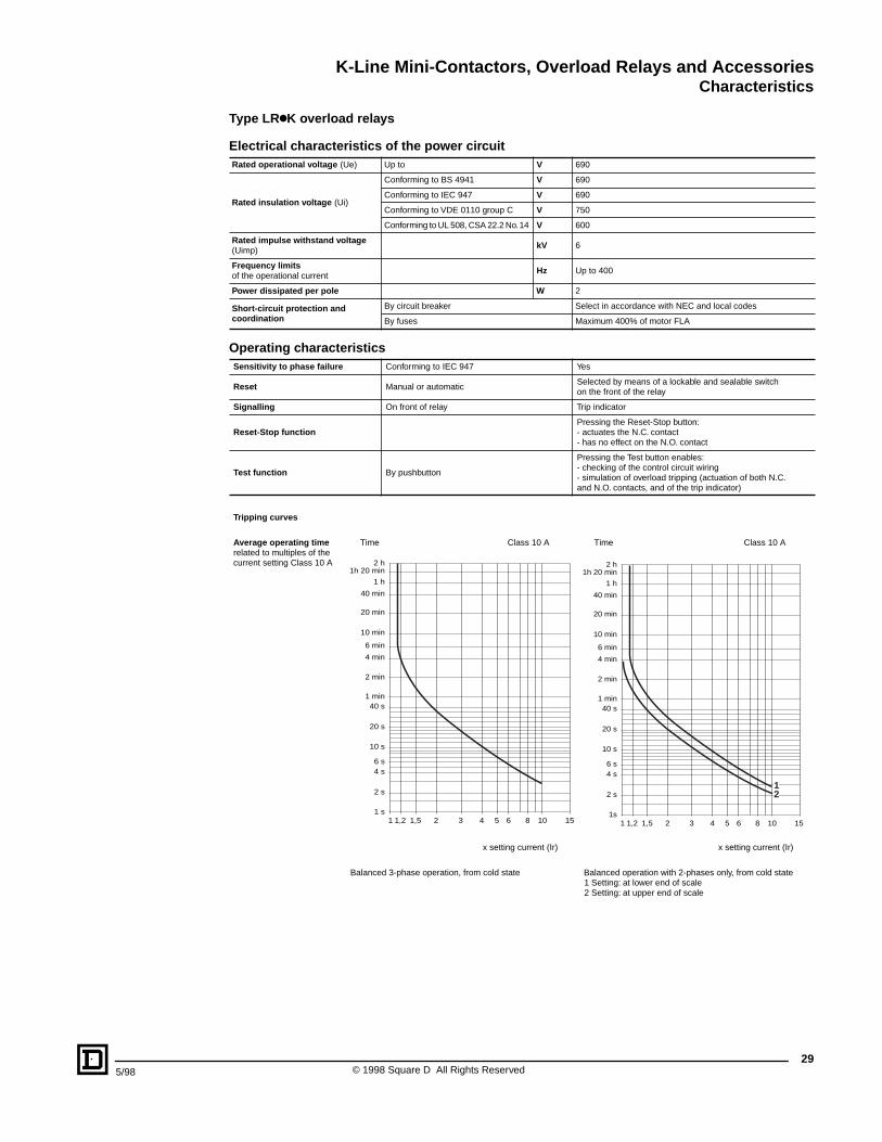
Type LRkK overload relays
Electrical characteristics of the power circuitRated operational voltage (Ue) Up to V 690
Rated insulation voltage (Ui)
Conforming to BS 4941 V 690
Conforming to IEC 947 V 690
Conforming to VDE 0110 group C V 750
Conforming to UL 508, CSA 22.2 No. 14 V 600
Rated impulse withstand voltage (Uimp)
kV 6
Frequency limitsof the operational current
Hz Up to 400
Power dissipated per pole W 2
Short-circuit protection and coordination
By circuit breaker Select in accordance with NEC and local codes
By fuses Maximum 400% of motor FLA
Operating characteristicsSensitivity to phase failure Conforming to IEC 947 Yes
Reset Manual or automaticSelected by means of a lockable and sealable switchon the front of the relay
Signalling On front of relay Trip indicator
Reset-Stop functionPressing the Reset-Stop button:- actuates the N.C. contact- has no effect on the N.O. contact
Test function By pushbutton
Pressing the Test button enables:- checking of the control circuit wiring- simulation of overload tripping (actuation of both N.C. and N.O. contacts, and of the trip indicator)
Tripping curves
Average operating time related to multiples of the current setting Class 10 A
Time Class 10 A Time Class 10 A
x setting current (Ir) x setting current (Ir)
Balanced 3-phase operation, from cold state Balanced operation with 2-phases only, from cold state1 Setting: at lower end of scale2 Setting: at upper end of scale
2 h 1h 20 min
1 h
40 min
20 min
10 min
6 min
4 min
2 min
1 min40 s
20 s
10 s
6 s4 s
2 s
1 s1 1,2 1,5 2 3 4 5 6 8 10 15
2 h1h 20 min
1 h
40 min
20 min
10 min
6 min
4 min
2 min
1 min40 s
20 s
10 s
6 s4 s
2 s
1s1 1,2 1,5 2 3 4 5 6 8 10 15
12
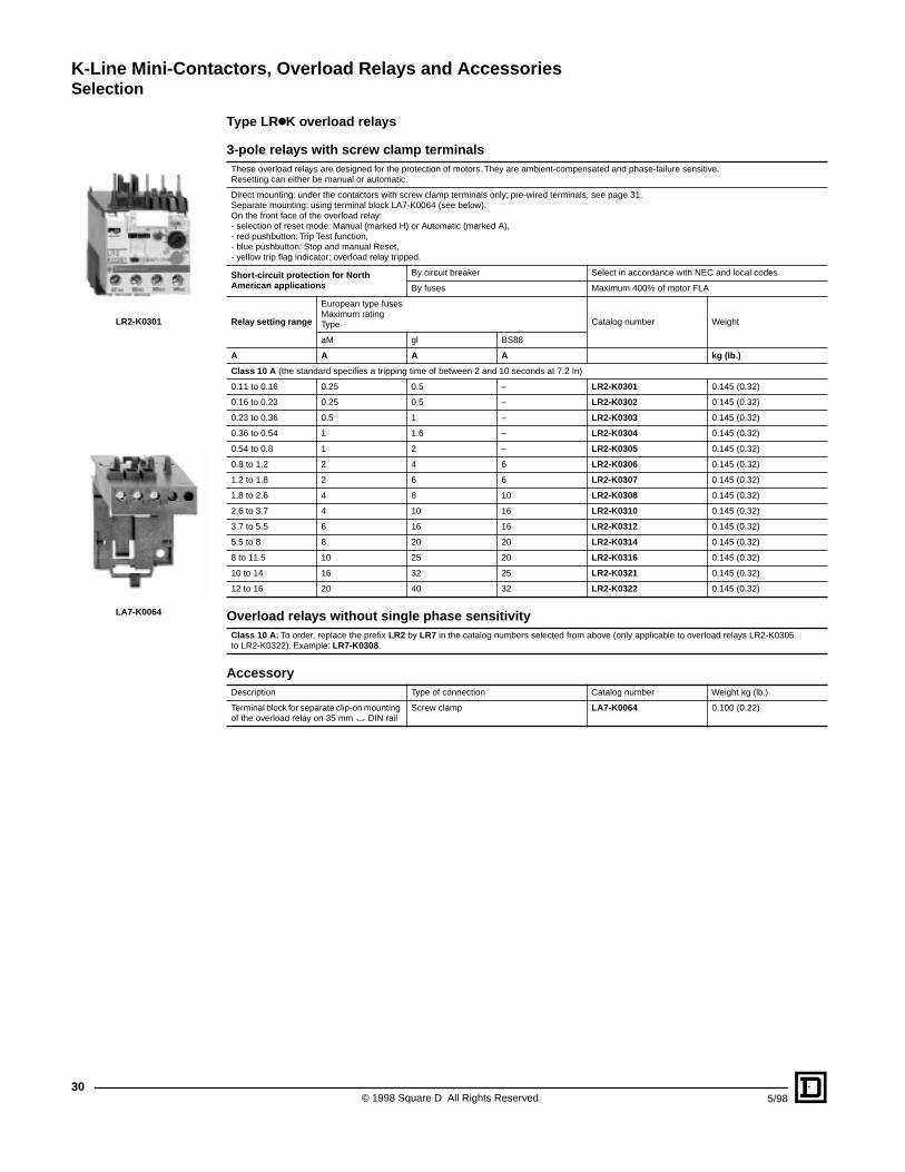
K-Line Mini-Contactors, Overload Relays and AccessoriesSelection
© 1998 Square D All Rights Reserved30
5/98
Type LRkK overload relays
3-pole relays with screw clamp terminalsThese overload relays are designed for the protection of motors. They are ambient-compensated and phase-failure sensitive. Resetting can either be manual or automatic.
Direct mounting: under the contactors with screw clamp terminals only; pre-wired terminals, see page 31.Separate mounting: using terminal block LA7-K0064 (see below).On the front face of the overload relay:- selection of reset mode: Manual (marked H) or Automatic (marked A),- red pushbutton: Trip Test function,- blue pushbutton: Stop and manual Reset,- yellow trip flag indicator: overload relay tripped.
Short-circuit protection for North American applications
By circuit breaker Select in accordance with NEC and local codes
By fuses Maximum 400% of motor FLA
Relay setting range
European type fusesMaximum ratingType Catalog number Weight
aM gl BS88
A A A A kg (lb.)
Class 10 A (the standard specifies a tripping time of between 2 and 10 seconds at 7.2 In)
0.11 to 0.16 0.25 0.5 – LR2-K0301 0.145 (0.32)
0.16 to 0.23 0.25 0.5 – LR2-K0302 0.145 (0.32)
0.23 to 0.36 0.5 1 – LR2-K0303 0.145 (0.32)
0.36 to 0.54 1 1.6 – LR2-K0304 0.145 (0.32)
0.54 to 0.8 1 2 – LR2-K0305 0.145 (0.32)
0.8 to 1.2 2 4 6 LR2-K0306 0.145 (0.32)
1.2 to 1.8 2 6 6 LR2-K0307 0.145 (0.32)
1.8 to 2.6 4 8 10 LR2-K0308 0.145 (0.32)
2.6 to 3.7 4 10 16 LR2-K0310 0.145 (0.32)
3.7 to 5.5 6 16 16 LR2-K0312 0.145 (0.32)
5.5 to 8 8 20 20 LR2-K0314 0.145 (0.32)
8 to 11.5 10 25 20 LR2-K0316 0.145 (0.32)
10 to 14 16 32 25 LR2-K0321 0.145 (0.32)
12 to 16 20 40 32 LR2-K0322 0.145 (0.32)
Overload relays without single phase sensitivityClass 10 A: To order, replace the prefix LR2 by LR7 in the catalog numbers selected from above (only applicable to overload relays LR2-K0305 to LR2-K0322). Example: LR7-K0308.
AccessoryDescription Type of connection Catalog number Weight kg (lb.)
Terminal block for separate clip-on mounting of the overload relay on 35 mm " DIN rail
Screw clamp LA7-K0064 0.100 (0.22)
LR2-K0301
LA7-K0064
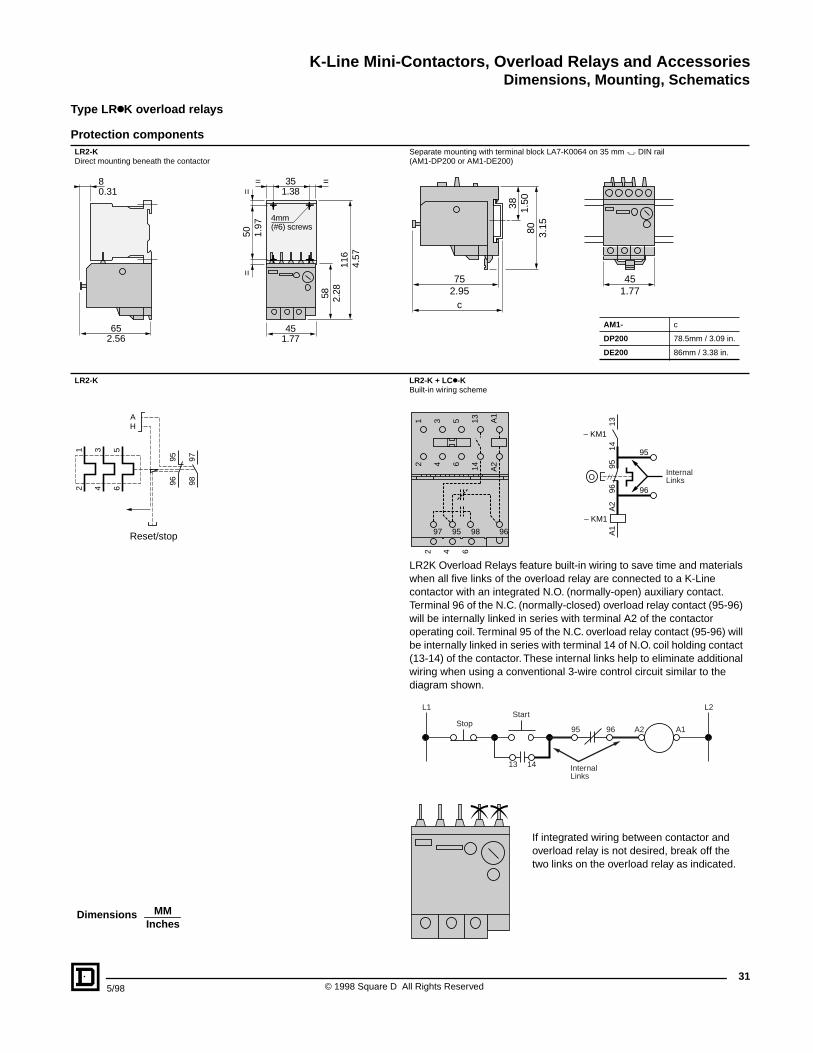
K-Line Mini-Contactors, Overload Relays and AccessoriesDimensions, Mounting, Schematics
315/98 © 1998 Square D All Rights Reserved
Type LRkK overload relays
Protection componentsLR2-KDirect mounting beneath the contactor
Separate mounting with terminal block LA7-K0064 on 35 mm " DIN rail (AM1-DP200 or AM1-DE200)
AM1- c
DP200 78.5mm / 3.09 in.
DE200 86mm / 3.38 in.
LR2-K LR2-K + LCk-KBuilt-in wiring scheme
LR2K Overload Relays feature built-in wiring to save time and materials when all five links of the overload relay are connected to a K-Line contactor with an integrated N.O. (normally-open) auxiliary contact. Terminal 96 of the N.C. (normally-closed) overload relay contact (95-96) will be internally linked in series with terminal A2 of the contactor operating coil. Terminal 95 of the N.C. overload relay contact (95-96) will be internally linked in series with terminal 14 of N.O. coil holding contact (13-14) of the contactor. These internal links help to eliminate additional wiring when using a conventional 3-wire control circuit similar to the diagram shown.
If integrated wiring between contactor and overload relay is not desired, break off the two links on the overload relay as indicated.
65
8
==
35= =
4mm (#6) screws
452.56
0.31 1.38
1.77
58
50
116
2.28
1.97
4.57
38
801.
50
3.15
2.95 1.7775
c
45
1 3 5
2 4 6
9798
9596
AH
Reset/stop
Internal Links
1 3 5 13 A1
2 4 6 14 A2
2 4 6
97 95 98 96
– KM1
A2
A1
9695
1314
– KM1
O
95
96
StopStart
L1
13 14
95 96 A2 A1
L2
InternalLinks
MMInches
Dimensions
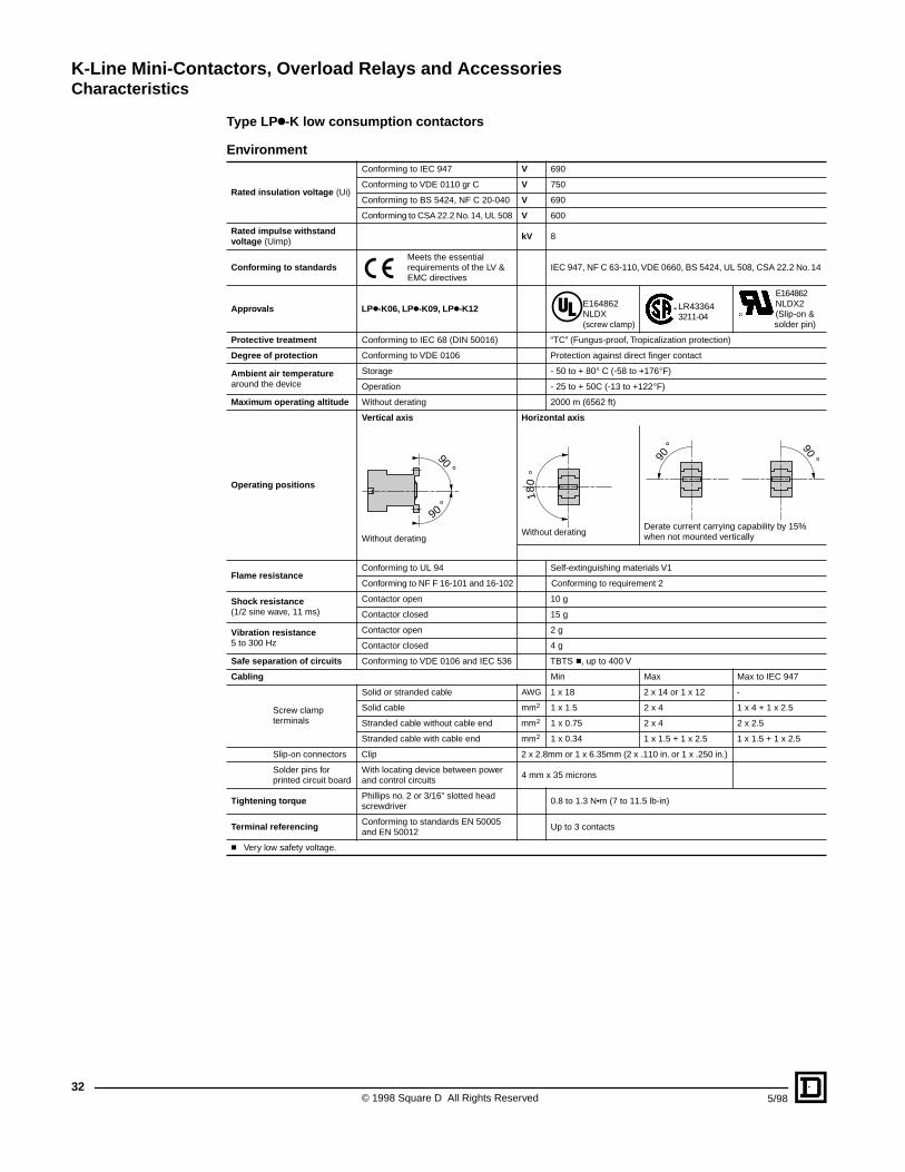
K-Line Mini-Contactors, Overload Relays and AccessoriesCharacteristics
© 1998 Square D All Rights Reserved32
5/98
Type LPk-K low consumption contactors
Environment
Rated insulation voltage (Ui)
Conforming to IEC 947 V 690
Conforming to VDE 0110 gr C V 750
Conforming to BS 5424, NF C 20-040 V 690
Conforming to CSA 22.2 No. 14, UL 508 V 600
Rated impulse withstand voltage (Uimp)
kV 8
Conforming to standardsMeets the essential requirements of the LV & EMC directives
IEC 947, NF C 63-110, VDE 0660, BS 5424, UL 508, CSA 22.2 No. 14
Approvals LPk-K06, LPk-K09, LPk-K12 E164862NLDX (screw clamp)
LR433643211-04
E164862NLDX2(Slip-on &
solder pin)
Protective treatment Conforming to IEC 68 (DIN 50016) “TC” (Fungus-proof, Tropicalization protection)
Degree of protection Conforming to VDE 0106 Protection against direct finger contact
Ambient air temperature around the device
Storage - 50 to + 80° C (-58 to +176°F)
Operation - 25 to + 50C (-13 to +122°F)
Maximum operating altitude Without derating 2000 m (6562 ft)
Operating positions
Vertical axis Horizontal axis
Without deratingWithout derating
Derate current carrying capability by 15% when not mounted vertically
Flame resistanceConforming to UL 94 Self-extinguishing materials V1
Conforming to NF F 16-101 and 16-102 Conforming to requirement 2
Shock resistance (1/2 sine wave, 11 ms)
Contactor open 10 g
Contactor closed 15 g
Vibration resistance5 to 300 Hz
Contactor open 2 g
Contactor closed 4 g
Safe separation of circuits Conforming to VDE 0106 and IEC 536 TBTS c, up to 400 V
Cabling Min Max Max to IEC 947
Screw clamp terminals
Solid or stranded cable AWG 1 x 18 2 x 14 or 1 x 12 -
Solid cable mm2 1 x 1.5 2 x 4 1 x 4 + 1 x 2.5
Stranded cable without cable end mm2 1 x 0.75 2 x 4 2 x 2.5
Stranded cable with cable end mm2 1 x 0.34 1 x 1.5 + 1 x 2.5 1 x 1.5 + 1 x 2.5
Slip-on connectors Clip 2 x 2.8mm or 1 x 6.35mm (2 x .110 in. or 1 x .250 in.)
Solder pins for printed circuit board
With locating device between power and control circuits
4 mm x 35 microns
Tightening torque Phillips no. 2 or 3/16" slotted head screwdriver
0.8 to 1.3 N•m (7 to 11.5 lb-in)
Terminal referencing Conforming to standards EN 50005 and EN 50012
Up to 3 contacts
c Very low safety voltage.
90 °
90 °
180
°
90 ° 90 °
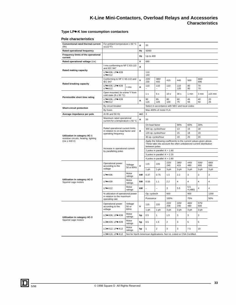
K-Line Mini-Contactors, Overload Relays and AccessoriesCharacteristics
335/98 © 1998 Square D All Rights Reserved
Type LPk-K low consumption contactors
Pole characteristicsConventional rated thermal current (Ith)
For ambient temperature ≤ 50 °C (≤122°F)
A 20
Rated operational frequency Hz 50/60
Frequency limits of the operational current Hz Up to 400
Rated operational voltage (Ue) V 690
Rated making capacity
I rms conforming to NF C 63-110 and IEC 947
A
LPk-K06, LPk-K09 LPk-K12
110144
Rated breaking capacity
Conforming to NF C 63-110 and IEC 947
V 220/230
380/400
415 440 500660/690
LPk-K06, LPk-K09 LPk-K12
I rms A 110–
110–
110–
110120
8080
7070
Permissible short time rating
Open mounted, for a time “t” from cold state (θ ≤ 50 °C)
1 s 5 s 10 s 30 s 1 min 3 min ≥15 min
LPk-K06, LPk-K09 LPk-K12
A 90115
85105
80100
6075
4555
4050
2025
Short-circuit protectionBy circuit breaker Select in accordance with NEC and local codes
By fuses Max 400% of motor FLA
Average impedance per pole At Ith and 50 Hz mΩ 3
Utilization in category AC-1 resistive circuits, heating, lighting (Ue ≤ 440 V)
Maximum rated operational current for a temperature ≤ 50 °C A 20
Rated operational current limits in relation to on-load factor and operating frequency
A
On-load factor 90% 60% 30%
300 op. cycles/hour 13 15 18
120 op. cycles/hour 15 18 19
30 op. cycles/hour 19 20 20
Increase in operational current by paralleling poles
Apply the following coefficients to the current values given above. These take into account the often unbalanced current distribution between poles
2 poles in parallel: K = 1.60
3 poles in parallel: K = 2.25
4 poles in parallel: K = 2.80
Utilization in category AC-3Squirrel cage motors
Operational poweraccording to the voltage
Voltage50 or 60Hz
V115 220
220/240
380/415
440/480
500/600
660/690
1-ph 1-ph 3-ph 3-ph 3-ph 3-ph 3-ph
LPk-K06Motorratings
kW 0.37 0.75 1.5 2.2 3 3 3
LPk-K09Motor ratings
kW 0.55 1.1 2.2 4 4 4 4
LPk-K12Motor ratings
kW – – 3 5.55.54 (480)
4 4
% utilization of operational powerin relation to the maximum operating rate
Op. cycles/h 600 900 1200
Puissance 100% 75% 50%
Utilization in category AC-3Squirrel cage motors
Operational poweraccording to the voltage
Voltage50 or 60Hz
V115 220
220/ 208
220/240
460/480
575/600
1-ph 1-ph 3-ph 3-ph 3-ph 3-ph
LCk-K06, LPk-K06Motor ratings
hp 0.5 1 1.5 3 3 3
LCk-K09, LPk-K09Motor ratings
hp 0.5 1.5 2 3 5 5
LCk-K12, LPk-K12Motor ratings
hp 1 2 3 3 7.5 10
LCk-K16, LPk-K12 Not for North American Applications. Not UL Listed or CSA Certified.
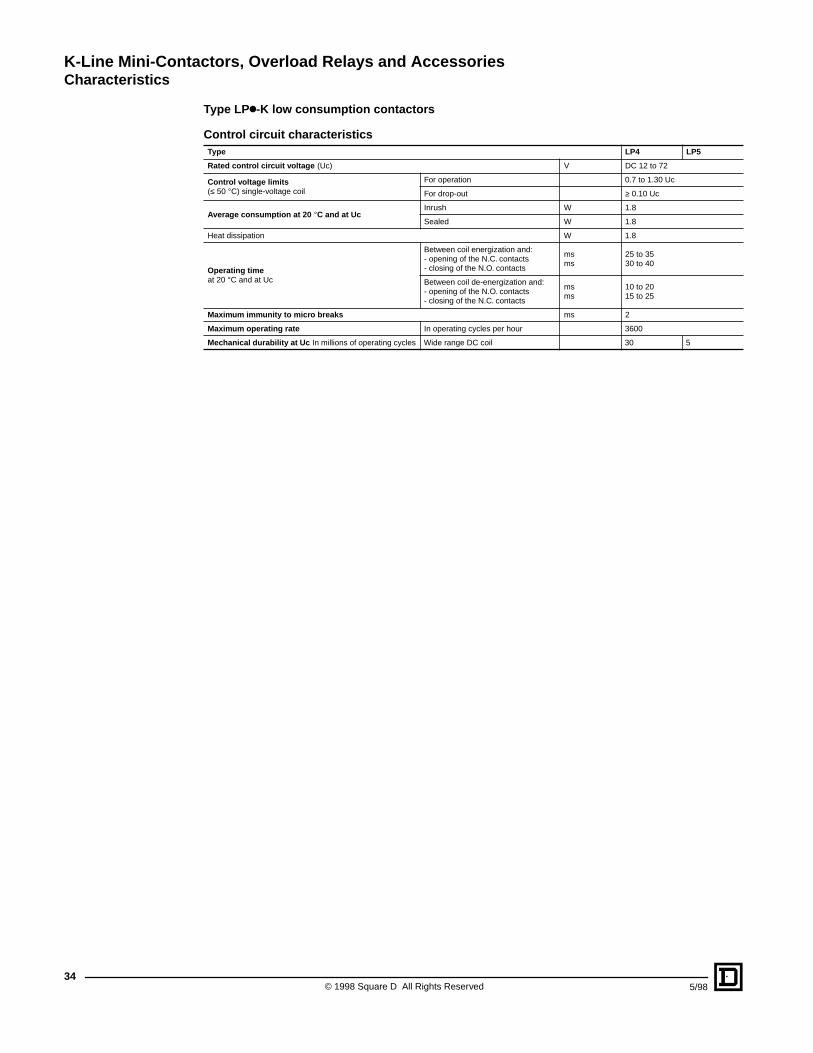
K-Line Mini-Contactors, Overload Relays and AccessoriesCharacteristics
© 1998 Square D All Rights Reserved34
5/98
Type LPk-K low consumption contactors
Control circuit characteristicsType LP4 LP5
Rated control circuit voltage (Uc) V DC 12 to 72
Control voltage limits(≤ 50 °C) single-voltage coil
For operation 0.7 to 1.30 Uc
For drop-out ≥ 0.10 Uc
Average consumption at 20 °C and at UcInrush W 1.8
Sealed W 1.8
Heat dissipation W 1.8
Operating timeat 20 °C and at Uc
Between coil energization and:- opening of the N.C. contacts- closing of the N.O. contacts
msms
25 to 3530 to 40
Between coil de-energization and:- opening of the N.O. contacts- closing of the N.C. contacts
msms
10 to 2015 to 25
Maximum immunity to micro breaks ms 2
Maximum operating rate In operating cycles per hour 3600
Mechanical durability at Uc In millions of operating cycles Wide range DC coil 30 5
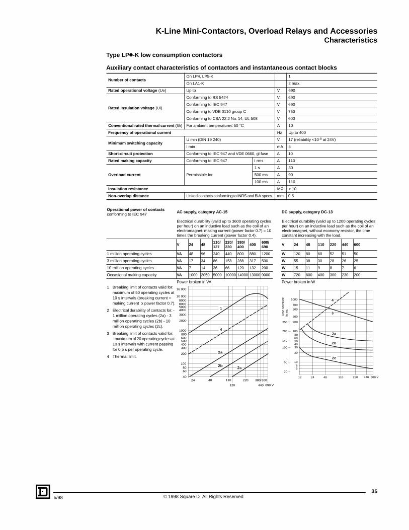
K-Line Mini-Contactors, Overload Relays and AccessoriesCharacteristics
355/98 © 1998 Square D All Rights Reserved
Type LPk-K low consumption contactors
Auxiliary contact characteristics of contactors and instantaneous contact blocks
Number of contactsOn LP4, LP5-K 1
On LA1-K 2 max.
Rated operational voltage (Ue) Up to V 690
Rated insulation voltage (Ui)
Conforming to BS 5424 V 690
Conforming to IEC 947 V 690
Conforming to VDE 0110 group C V 750
Conforming to CSA 22.2 No. 14, UL 508 V 600
Conventional rated thermal current (lth) For ambient temperature≤ 50 °C A 10
Frequency of operational current Hz Up to 400
Minimum switching capacityU min (DIN 19 240) V 17 (reliability <10-8 at 24V)
I min mA 5
Short-circuit protection Conforming to IEC 947 and VDE 0660, gl fuse A 10
Rated making capacity Conforming to IEC 947 I rms A 110
Overload current Permissible for
1 s A 80
500 ms A 90
100 ms A 110
Insulation resistance MΩ > 10
Non-overlap distance Linked contacts conforming to INRS and BIA specs. mm 0.5
Operational power of contacts conforming to IEC 947
AC supply, category AC-15 DC supply, category DC-13
Electrical durability (valid up to 3600 operating cycles per hour) on an inductive load such as the coil of an electromagnet: making current (power factor 0.7) = 10 times the breaking current (power factor 0.4).
Electrical durability (valid up to 1200 operating cycles per hour) on an inductive load such as the coil of an electromagnet, without economy resistor, the time constant increasing with the load.
V 24 48 110/127
220/230
380/400 400 600/
690 V 24 48 110 220 440 600
1 million operating cycles VA 48 96 240 440 800 880 1200 W 120 80 60 52 51 50
3 million operating cycles VA 17 34 86 158 288 317 500 W 55 38 30 28 26 25
10 million operating cycles VA 7 14 36 66 120 132 200 W 15 11 9 8 7 6
Occasional making capacity VA 1000 2050 5000 10000 14000 13000 9000 W 720 600 400 300 230 200
1 Breaking limit of contacts valid for: maximum of 50 operating cycles at 10 s intervals (breaking current = making current x power factor 0.7).
Power broken in VA Power broken in W
2 Electrical durability of contacts for: - 1 million operating cycles (2a) - 3 million operating cycles (2b) - 10 million operating cycles (2c).
3 Breaking limit of contacts valid for:- maximum of 20 operating cycles at 10 s intervals with current passing for 0.5 s per operating cycle.
4 Thermal limit.
10 000
5000
3000
2000
1000800600500400300
200
1008060
24 48 110 220
440 690 V120
380 50040
16 000
80006000
4000
2c2b
4
1
2a
1000
700
500
300
200
1008060504030
20
1086
12 24 48 110 220 440 600 V
250
200
140
100
50
20
2c
2b
2a
3
4
Tim
e co
nsta
nt
in m
s
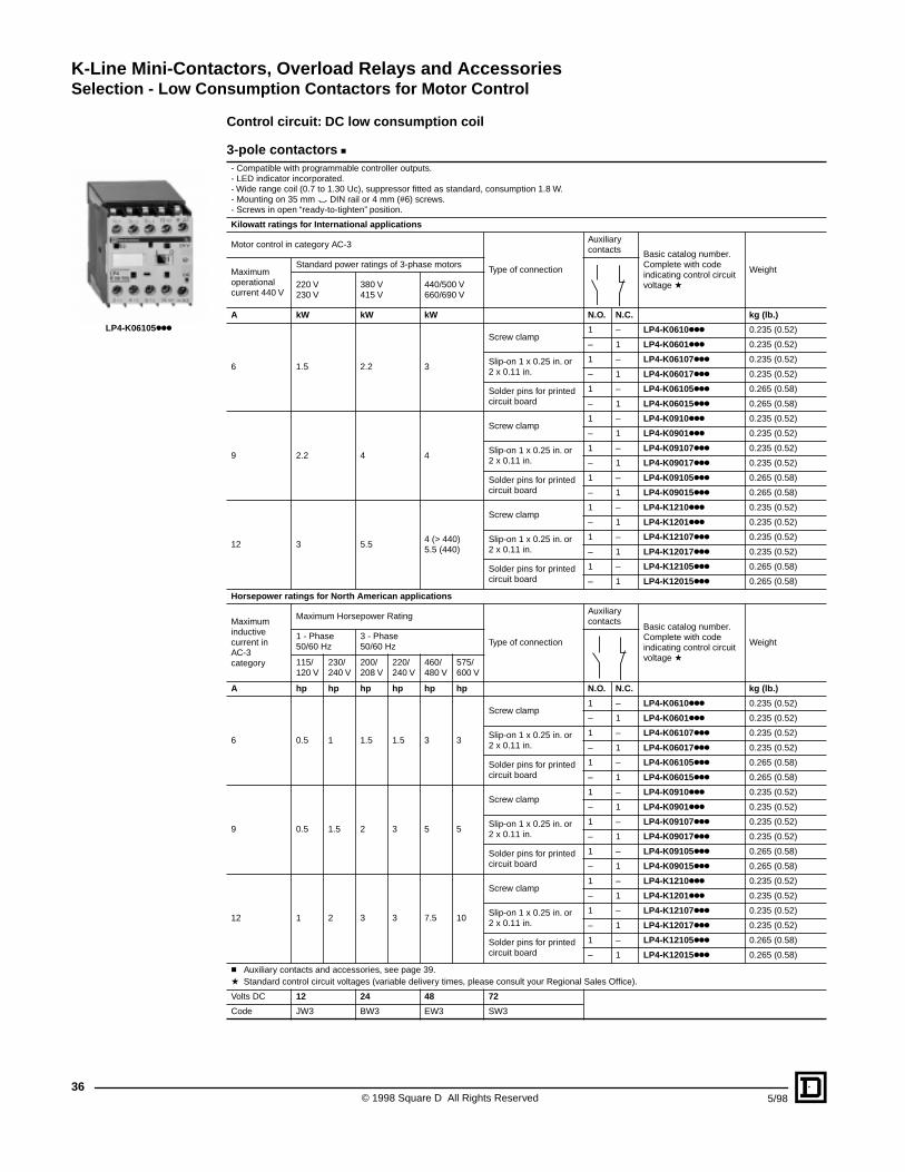
K-Line Mini-Contactors, Overload Relays and AccessoriesSelection - Low Consumption Contactors for Motor Control
© 1998 Square D All Rights Reserved36
5/98
Control circuit: DC low consumption coil
3-pole contactors c- Compatible with programmable controller outputs.- LED indicator incorporated.- Wide range coil (0.7 to 1.30 Uc), suppressor fitted as standard, consumption 1.8 W.- Mounting on 35 mm " DIN rail or 4 mm (#6) screws.- Screws in open “ready-to-tighten” position.
Kilowatt ratings for International applications
Motor control in category AC-3
Type of connection
Auxiliary contacts Basic catalog number.
Complete with code indicating control circuit voltage a
WeightMaximum operational current 440 V
Standard power ratings of 3-phase motors
220 V230 V
380 V415 V
440/500 V660/690 V
A kW kW kW N.O. N.C. kg (lb.)
6 1.5 2.2 3
Screw clamp1 – LP4-K0610kkk 0.235 (0.52)
– 1 LP4-K0601kkk 0.235 (0.52)
Slip-on 1 x 0.25 in. or 2 x 0.11 in.
1 – LP4-K06107kkk 0.235 (0.52)
– 1 LP4-K06017kkk 0.235 (0.52)
Solder pins for printed circuit board
1 – LP4-K06105kkk 0.265 (0.58)
– 1 LP4-K06015kkk 0.265 (0.58)
9 2.2 4 4
Screw clamp1 – LP4-K0910kkk 0.235 (0.52)
– 1 LP4-K0901kkk 0.235 (0.52)
Slip-on 1 x 0.25 in. or 2 x 0.11 in.
1 – LP4-K09107kkk 0.235 (0.52)
– 1 LP4-K09017kkk 0.235 (0.52)
Solder pins for printed circuit board
1 – LP4-K09105kkk 0.265 (0.58)
– 1 LP4-K09015kkk 0.265 (0.58)
12 3 5.54 (> 440)5.5 (440)
Screw clamp1 – LP4-K1210kkk 0.235 (0.52)
– 1 LP4-K1201kkk 0.235 (0.52)
Slip-on 1 x 0.25 in. or 2 x 0.11 in.
1 – LP4-K12107kkk 0.235 (0.52)
– 1 LP4-K12017kkk 0.235 (0.52)
Solder pins for printed circuit board
1 – LP4-K12105kkk 0.265 (0.58)
– 1 LP4-K12015kkk 0.265 (0.58)
Horsepower ratings for North American applications
Maximum inductive current in AC-3 category
Maximum Horsepower Rating
Type of connection
Auxiliary contacts
Basic catalog number. Complete with code indicating control circuit voltage a
Weight 1 - Phase50/60 Hz
3 - Phase50/60 Hz
115/ 120 V
230/ 240 V
200/ 208 V
220/ 240 V
460/ 480 V
575/ 600 V
A hp hp hp hp hp hp N.O. N.C. kg (lb.)
6 0.5 1 1.5 1.5 3 3
Screw clamp1 – LP4-K0610kkk 0.235 (0.52)
– 1 LP4-K0601kkk 0.235 (0.52)
Slip-on 1 x 0.25 in. or 2 x 0.11 in.
1 – LP4-K06107kkk 0.235 (0.52)
– 1 LP4-K06017kkk 0.235 (0.52)
Solder pins for printed circuit board
1 – LP4-K06105kkk 0.265 (0.58)
– 1 LP4-K06015kkk 0.265 (0.58)
9 0.5 1.5 2 3 5 5
Screw clamp1 – LP4-K0910kkk 0.235 (0.52)
– 1 LP4-K0901kkk 0.235 (0.52)
Slip-on 1 x 0.25 in. or 2 x 0.11 in.
1 – LP4-K09107kkk 0.235 (0.52)
– 1 LP4-K09017kkk 0.235 (0.52)
Solder pins for printed circuit board
1 – LP4-K09105kkk 0.265 (0.58)
– 1 LP4-K09015kkk 0.265 (0.58)
12 1 2 3 3 7.5 10
Screw clamp1 – LP4-K1210kkk 0.235 (0.52)
– 1 LP4-K1201kkk 0.235 (0.52)
Slip-on 1 x 0.25 in. or 2 x 0.11 in.
1 – LP4-K12107kkk 0.235 (0.52)
– 1 LP4-K12017kkk 0.235 (0.52)
Solder pins for printed circuit board
1 – LP4-K12105kkk 0.265 (0.58)
– 1 LP4-K12015kkk 0.265 (0.58)
c Auxiliary contacts and accessories, see page 39.a Standard control circuit voltages (variable delivery times, please consult your Regional Sales Office).
Volts DC 12 24 48 72
Code JW3 BW3 EW3 SW3
LP4-K06105kkk
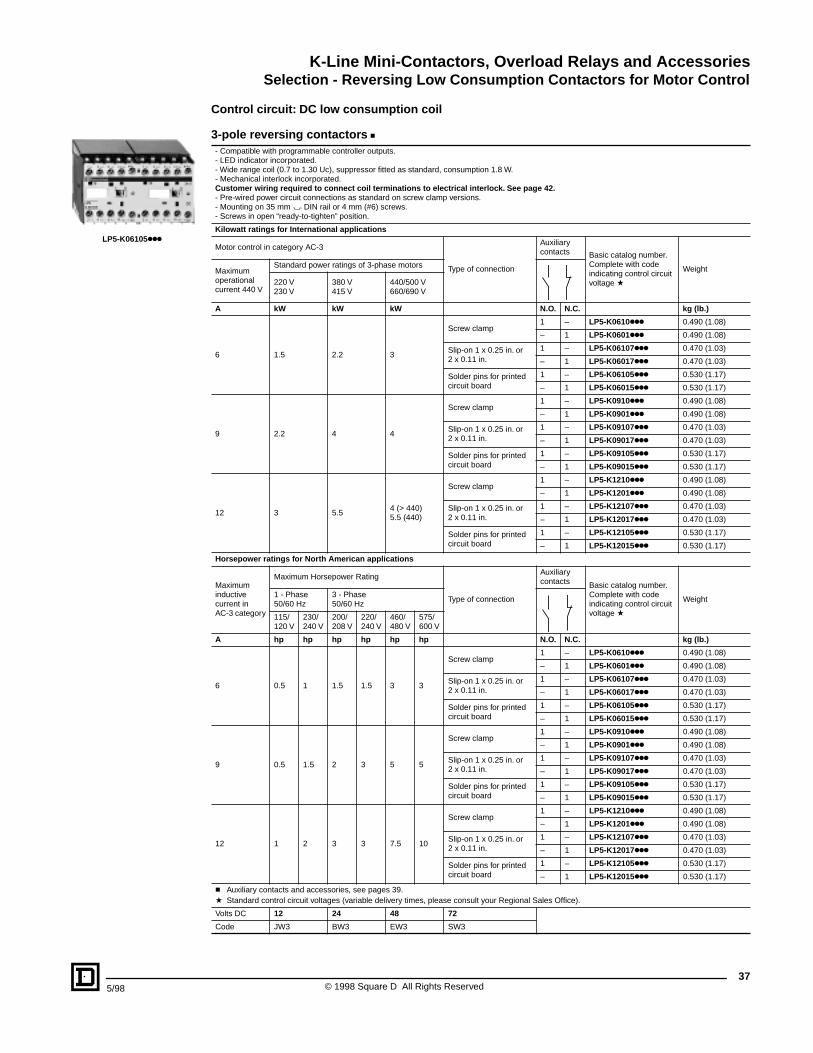
K-Line Mini-Contactors, Overload Relays and AccessoriesSelection - Reversing Low Consumption Contactors for Motor Control
375/98 © 1998 Square D All Rights Reserved
Control circuit: DC low consumption coil
3-pole reversing contactors c- Compatible with programmable controller outputs.- LED indicator incorporated.- Wide range coil (0.7 to 1.30 Uc), suppressor fitted as standard, consumption 1.8 W.- Mechanical interlock incorporated.Customer wiring required to connect coil terminations to electrical interlock. See page 42.- Pre-wired power circuit connections as standard on screw clamp versions.- Mounting on 35 mm " DIN rail or 4 mm (#6) screws.- Screws in open “ready-to-tighten” position.
Kilowatt ratings for International applications
Motor control in category AC-3
Type of connection
Auxiliary contacts Basic catalog number.
Complete with code indicating control circuit voltage a
WeightMaximum operational current 440 V
Standard power ratings of 3-phase motors
220 V230 V
380 V415 V
440/500 V660/690 V
A kW kW kW N.O. N.C. kg (lb.)
6 1.5 2.2 3
Screw clamp1 – LP5-K0610kkk 0.490 (1.08)
– 1 LP5-K0601kkk 0.490 (1.08)
Slip-on 1 x 0.25 in. or 2 x 0.11 in.
1 – LP5-K06107kkk 0.470 (1.03)
– 1 LP5-K06017kkk 0.470 (1.03)
Solder pins for printed circuit board
1 – LP5-K06105kkk 0.530 (1.17)
– 1 LP5-K06015kkk 0.530 (1.17)
9 2.2 4 4
Screw clamp1 – LP5-K0910kkk 0.490 (1.08)
– 1 LP5-K0901kkk 0.490 (1.08)
Slip-on 1 x 0.25 in. or 2 x 0.11 in.
1 – LP5-K09107kkk 0.470 (1.03)
– 1 LP5-K09017kkk 0.470 (1.03)
Solder pins for printed circuit board
1 – LP5-K09105kkk 0.530 (1.17)
– 1 LP5-K09015kkk 0.530 (1.17)
12 3 5.54 (> 440)5.5 (440)
Screw clamp1 – LP5-K1210kkk 0.490 (1.08)
– 1 LP5-K1201kkk 0.490 (1.08)
Slip-on 1 x 0.25 in. or 2 x 0.11 in.
1 – LP5-K12107kkk 0.470 (1.03)
– 1 LP5-K12017kkk 0.470 (1.03)
Solder pins for printed circuit board
1 – LP5-K12105kkk 0.530 (1.17)
– 1 LP5-K12015kkk 0.530 (1.17)
Horsepower ratings for North American applications
Maximum inductive current in AC-3 category
Maximum Horsepower Rating
Type of connection
Auxiliary contacts Basic catalog number.
Complete with code indicating control circuit voltage a
Weight 1 - Phase50/60 Hz
3 - Phase50/60 Hz
115/ 120 V
230/ 240 V
200/ 208 V
220/ 240 V
460/ 480 V
575/ 600 V
A hp hp hp hp hp hp N.O. N.C. kg (lb.)
6 0.5 1 1.5 1.5 3 3
Screw clamp1 – LP5-K0610kkk 0.490 (1.08)
– 1 LP5-K0601kkk 0.490 (1.08)
Slip-on 1 x 0.25 in. or 2 x 0.11 in.
1 – LP5-K06107kkk 0.470 (1.03)
– 1 LP5-K06017kkk 0.470 (1.03)
Solder pins for printed circuit board
1 – LP5-K06105kkk 0.530 (1.17)
– 1 LP5-K06015kkk 0.530 (1.17)
9 0.5 1.5 2 3 5 5
Screw clamp1 – LP5-K0910kkk 0.490 (1.08)
– 1 LP5-K0901kkk 0.490 (1.08)
Slip-on 1 x 0.25 in. or 2 x 0.11 in.
1 – LP5-K09107kkk 0.470 (1.03)
– 1 LP5-K09017kkk 0.470 (1.03)
Solder pins for printed circuit board
1 – LP5-K09105kkk 0.530 (1.17)
– 1 LP5-K09015kkk 0.530 (1.17)
12 1 2 3 3 7.5 10
Screw clamp1 – LP5-K1210kkk 0.490 (1.08)
– 1 LP5-K1201kkk 0.490 (1.08)
Slip-on 1 x 0.25 in. or 2 x 0.11 in.
1 – LP5-K12107kkk 0.470 (1.03)
– 1 LP5-K12017kkk 0.470 (1.03)
Solder pins for printed circuit board
1 – LP5-K12105kkk 0.530 (1.17)
– 1 LP5-K12015kkk 0.530 (1.17)
c Auxiliary contacts and accessories, see pages 39.a Standard control circuit voltages (variable delivery times, please consult your Regional Sales Office).
Volts DC 12 24 48 72
Code JW3 BW3 EW3 SW3
LP5-K06105kkk
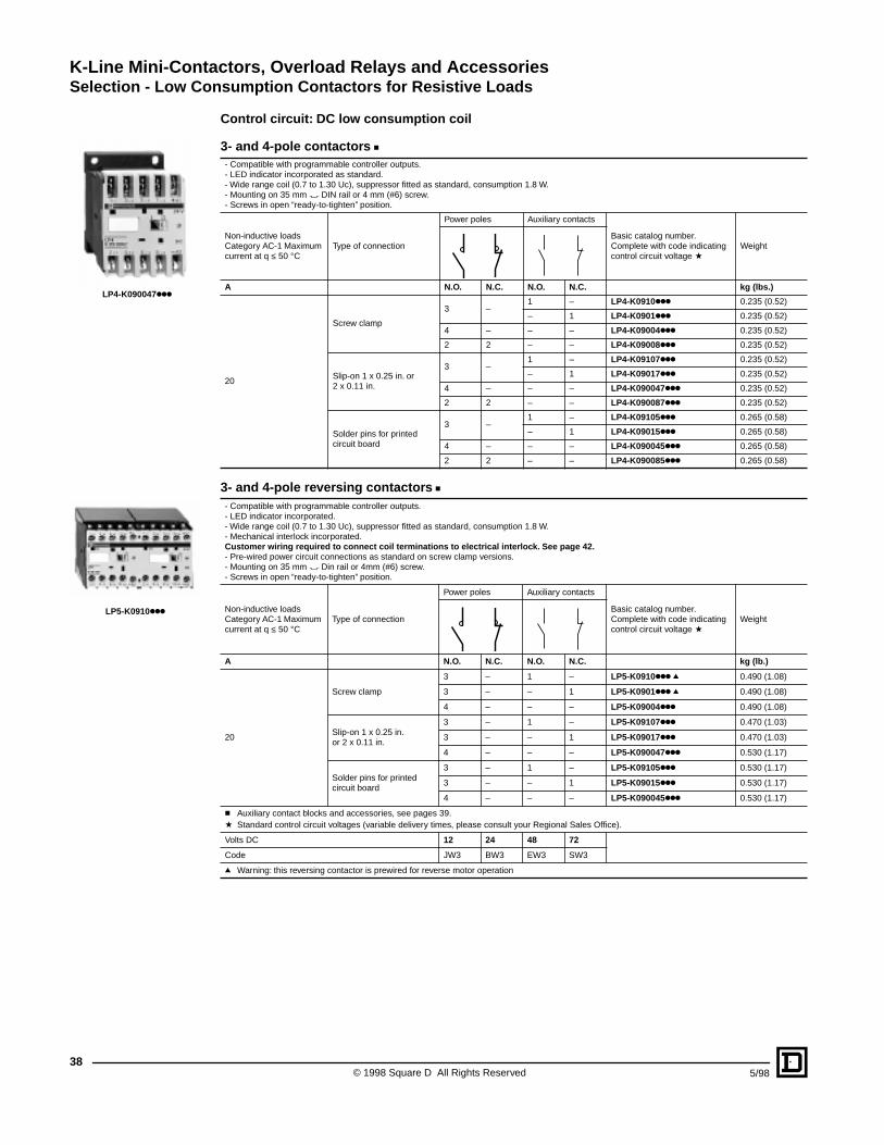
K-Line Mini-Contactors, Overload Relays and AccessoriesSelection - Low Consumption Contactors for Resistive Loads
© 1998 Square D All Rights Reserved38
5/98
Control circuit: DC low consumption coil
3- and 4-pole contactors c- Compatible with programmable controller outputs.- LED indicator incorporated as standard.- Wide range coil (0.7 to 1.30 Uc), suppressor fitted as standard, consumption 1.8 W.- Mounting on 35 mm " DIN rail or 4 mm (#6) screw.- Screws in open “ready-to-tighten” position.
Non-inductive loads Category AC-1 Maximum current at q ≤ 50 °C
Type of connection
Power poles Auxiliary contacts
Basic catalog number. Complete with code indicating control circuit voltage a
Weight
A N.O. N.C. N.O. N.C. kg (lbs.)
20
Screw clamp
3 –1 – LP4-K0910kkk 0.235 (0.52)
– 1 LP4-K0901kkk 0.235 (0.52)
4 – – – LP4-K09004kkk 0.235 (0.52)
2 2 – – LP4-K09008kkk 0.235 (0.52)
Slip-on 1 x 0.25 in. or2 x 0.11 in.
3 –1 – LP4-K09107kkk 0.235 (0.52)
– 1 LP4-K09017kkk 0.235 (0.52)
4 – – – LP4-K090047kkk 0.235 (0.52)
2 2 – – LP4-K090087kkk 0.235 (0.52)
Solder pins for printed circuit board
3 –1 – LP4-K09105kkk 0.265 (0.58)
– 1 LP4-K09015kkk 0.265 (0.58)
4 – – – LP4-K090045kkk 0.265 (0.58)
2 2 – – LP4-K090085kkk 0.265 (0.58)
3- and 4-pole reversing contactors c- Compatible with programmable controller outputs.- LED indicator incorporated.- Wide range coil (0.7 to 1.30 Uc), suppressor fitted as standard, consumption 1.8 W.- Mechanical interlock incorporated.Customer wiring required to connect coil terminations to electrical interlock. See page 42.- Pre-wired power circuit connections as standard on screw clamp versions.- Mounting on 35 mm " Din rail or 4mm (#6) screw.- Screws in open “ready-to-tighten” position.
Non-inductive loads Category AC-1 Maximum current at q ≤ 50 °C
Type of connection
Power poles Auxiliary contacts
Basic catalog number. Complete with code indicating control circuit voltage a
Weight
A N.O. N.C. N.O. N.C. kg (lb.)
20
Screw clamp
3 – 1 – LP5-K0910kkk q 0.490 (1.08)
3 – – 1 LP5-K0901kkk q 0.490 (1.08)
4 – – – LP5-K09004kkk 0.490 (1.08)
Slip-on 1 x 0.25 in.or 2 x 0.11 in.
3 – 1 – LP5-K09107kkk 0.470 (1.03)
3 – – 1 LP5-K09017kkk 0.470 (1.03)
4 – – – LP5-K090047kkk 0.530 (1.17)
Solder pins for printed circuit board
3 – 1 – LP5-K09105kkk 0.530 (1.17)
3 – – 1 LP5-K09015kkk 0.530 (1.17)
4 – – – LP5-K090045kkk 0.530 (1.17)
c Auxiliary contact blocks and accessories, see pages 39.a Standard control circuit voltages (variable delivery times, please consult your Regional Sales Office).
Volts DC 12 24 48 72
Code JW3 BW3 EW3 SW3
q Warning: this reversing contactor is prewired for reverse motor operation
LP4-K090047kkk
LP5-K0910kkk
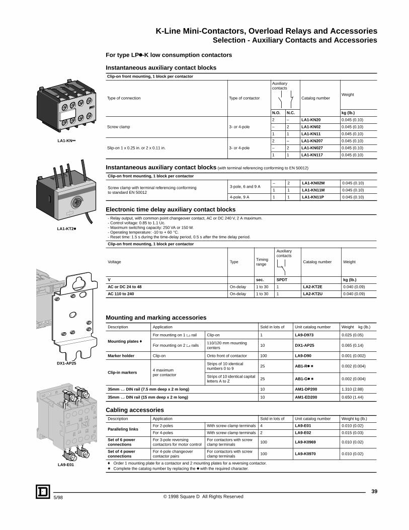
K-Line Mini-Contactors, Overload Relays and AccessoriesSelection - Auxiliary Contacts and Accessories
395/98 © 1998 Square D All Rights Reserved
For type LPk-K low consumption contactors
Instantaneous auxiliary contact blocksClip-on front mounting, 1 block per contactor
Type of connection Type of contactor
Auxiliary contacts
Catalog number Weight
N.O. N.C. kg (lb.)
Screw clamp 3- or 4-pole
2 – LA1-KN20 0.045 (0.10)
– 2 LA1-KN02 0.045 (0.10)
1 1 LA1-KN11 0.045 (0.10)
Slip-on 1 x 0.25 in. or 2 x 0.11 in. 3- or 4-pole
2 – LA1-KN207 0.045 (0.10)
– 2 LA1-KN027 0.045 (0.10)
1 1 LA1-KN117 0.045 (0.10)
Instantaneous auxiliary contact blocks (with terminal referencing conforming to EN 50012)
Clip-on front mounting, 1 block per contactor
Screw clamp with terminal referencing conforming to standard EN 50012
3-pole, 6 and 9 A– 2 LA1-KN02M 0.045 (0.10)
1 1 LA1-KN11M 0.045 (0.10)
4-pole, 9 A 1 1 LA1-KN11P 0.045 (0.10)
Electronic time delay auxiliary contact blocks- Relay output, with common point changeover contact, AC or DC 240 V, 2 A maximum.- Control voltage: 0.85 to 1.1 Uc.- Maximum switching capacity: 250 VA or 150 W.- Operating temperature: -10 to + 60 °C.- Reset time: 1.5 s during the time-delay period, 0.5 s after the time delay period.
Clip-on front mounting, 1 block per contactor
Voltage Type Timingrange
Auxiliary contacts
Catalog number Weight
V sec. SPDT kg (lb.)
AC or DC 24 to 48 On-delay 1 to 30 1 LA2-KT2E 0.040 (0.09)
AC 110 to 240 On-delay 1 to 30 1 LA2-KT2U 0.040 (0.09)
Mounting and marking accessoriesDescription Application Sold in lots of Unit catalog number Weight kg (lb.)
Mounting plates f
For mounting on 1 ' rail Clip-on 1 LA9-D973 0.025 (0.05)
For mounting on 2 ' rails110/120 mm mounting centers
10 DX1-AP25 0.065 (0.14)
Marker holder Clip-on Onto front of contactor 100 LA9-D90 0.001 (0.002)
Clip-in markers 4 maximumper contactor
Strips of 10 identical numbers 0 to 9
25 AB1-Rk t 0.002 (0.004)
Strips of 10 identical capital letters A to Z
25 AB1-Gk t 0.002 (0.004)
35mm " DIN rail (7.5 mm deep x 2 m long) 10 AM1-DP200 1.310 (2.88)
35mm " DIN rail (15 mm deep x 2 m long) 10 AM1-ED200 0.650 (1.44)
Cabling accessoriesDescription Application Sold in lots of Unit catalog number Weight kg (lb.)
Paralleling linksFor 2-poles With screw clamp terminals 4 LA9-E01 0.010 (0.02)
For 4-poles With screw clamp terminals 2 LA9-E02 0.015 (0.03)
Set of 6 power connections
For 3-pole reversing contactors for motor control
For contactors with screw clamp terminals
100 LA9-K0969 0.010 (0.02)
Set of 4 power connections
For 4-pole changeover contactor pairs
For contactors with screw clamp terminals
100 LA9-K0970 0.010 (0.02)
f Order 1 mounting plate for a contactor and 2 mounting plates for a reversing contactor.t Complete the catalog number by replacing the k with the required character.
LA1-KN••
LA1-KT2k
DX1-AP25
LA9-E01
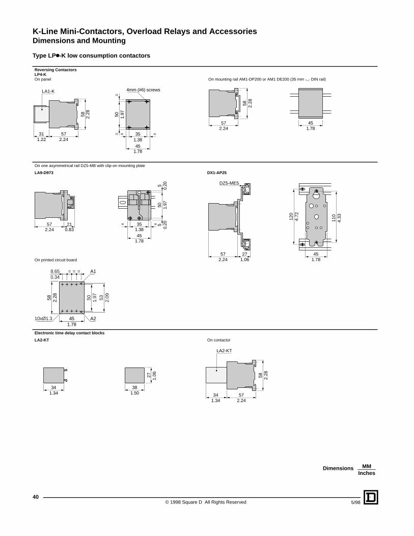
K-Line Mini-Contactors, Overload Relays and AccessoriesDimensions and Mounting
© 1998 Square D All Rights Reserved40
5/98
Type LPk-K low consumption contactors
Reversing Contactors LP4-K On panel On mounting rail AM1-DP200 or AM1 DE200 (35 mm " DIN rail)
On one asymmetrical rail DZ5-MB with clip-on mounting plate
LA9-D973 DX1-AP25
On printed circuit board
Electronic time delay contact blocks
LA2-KT On contactor
57312.241.22
LA1-K
58 2.28 50 1.97
==
351.3845
1.78
= =
4mm (#6) screws
57
58 2.28
452.24 1.78
45
35
1.78
1.38= =
505
51.
970.
200.
20572.24
210.83
110
4.33
451.78
120
4.72
572.24
271.06
DZ5-ME5
50 1.97 53 2.09
451.78
58 2.28
8.650.34
= = =
10xØ1.3
A1
A2
1.343834
1.50
27 1.06
57342.241.34
LA2-KT
58 2.28
MMInches
Dimensions
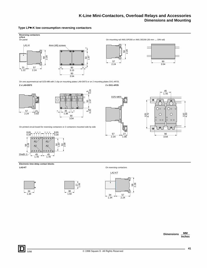
K-Line Mini-Contactors, Overload Relays and AccessoriesDimensions and Mounting
415/98 © 1998 Square D All Rights Reserved
Type LPk-K low consumption reversing contactors
Reversing contactors LP5-K On panel On mounting rail AM1-DP200 or AM1 DE200 (35 mm " DIN rail)
On one asymmetrical rail DZ5-MB with 2 clip-on mounting plates LA9-D973 or on 2 mounting plates DX1-AP25.
2 x LA9-D973 2 x DX1-AP25
On printed circuit board for reversing contactors or 2 contactors mounted side by side
Electronic time delay contact blocks
LA2-KT On reversing contactors
572.24
311.22
LA1-K58 2.28 50 1.97
==
903.54
803.15
4mm (#6) screws
==
57
58 2.28
902.24 3.54
90
35= =
505
51.
970.
200.
2057 21
3.54
1.382.24 0.83
57 272.24 1.06
DZ5-ME5
903.54
110
120
4.33
4.72
451.78
45
58
8.65 = = =
20xØ1.3
A1
A2 50
45
8.65
1.78
0.34
1.78
0.34===
53
2.28 1.97
2.09
A1
A2
1.343834
1.50
27 1.06
57342.241.34
LA2-KT
58 2.28
MMInches
Dimensions
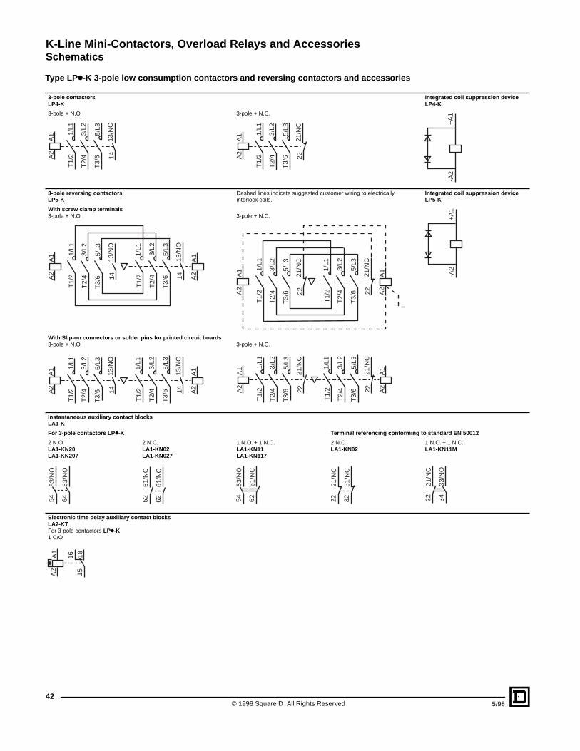
K-Line Mini-Contactors, Overload Relays and AccessoriesSchematics
© 1998 Square D All Rights Reserved42
5/98
Type LPk-K 3-pole low consumption contactors and reversing contactors and accessories
3-pole contactorsLP4-K
Integrated coil suppression deviceLP4-K
3-pole + N.O. 3-pole + N.C.
3-pole reversing contactors LP5-K
Dashed lines indicate suggested customer wiring to electrically interlock coils.
Integrated coil suppression device LP5-K
With screw clamp terminals3-pole + N.O. 3-pole + N.C.
With Slip-on connectors or solder pins for printed circuit boards3-pole + N.O. 3-pole + N.C.
Instantaneous auxiliary contact blocksLA1-K
For 3-pole contactors LPk-K Terminal referencing conforming to standard EN 50012
2 N.O. LA1-KN20LA1-KN207
2 N.C. LA1-KN02LA1-KN027
1 N.O. + 1 N.C. LA1-KN11LA1-KN117
2 N.C. LA1-KN02
1 N.O. + 1 N.C. LA1-KN11M
Electronic time delay auxiliary contact blocksLA2-KTFor 3-pole contactors LPk-K1 C/O
-A2
+A
1
A2
A1 1/
L1
3/L2
5/L3
13/N
O
T1/
2
T2/
4
T3/
6 14 A2
A1 1/
L1
3/L2
5/L3
21/N
C
T1/
2
T2/
4
T3/
6 22
-A2
+A
1
A2
A1 1/
L1
3/L2
5/L3
13/N
O
T1/
2
T2/
4
T3/
6 14
1/L1
3/L2
5/L3
13/N
O
T1/
2
T2/
4
T3/
6 14 A2
A1
A2
A1 1/
L1
3/L2
5/L3
21/N
C
T1/
2
T2/
4
T3/
6 22
1/L1
3/L2
5/L3
21/N
C
T1/
2
T2/
4
T3/
6 22 A2
A1
A2
A1 1/
L1
3/L2
5/L3
13/N
O
T1/
2
T2/
4
T3/
6 14
1/L1
3/L2
5/L3
13/N
O
T1/
2
T2/
4
T3/
6 14 A2
A1
A2
A1 1/
L1
3/L2
5/L3
21/N
C
T1/
2
T2/
4
T3/
6 22
1/L1
3/L2
5/L3
21/N
C
T1/
2
T2/
4
T3/
6 22 A2
A1
5453
/NO
6463
/NO
5251
/NC
6261
/NC
5453
/NO
6261
/NC
2221
/NC
3231
/NC
2221
/NC
3433
/NO
A2
A1
16 1815
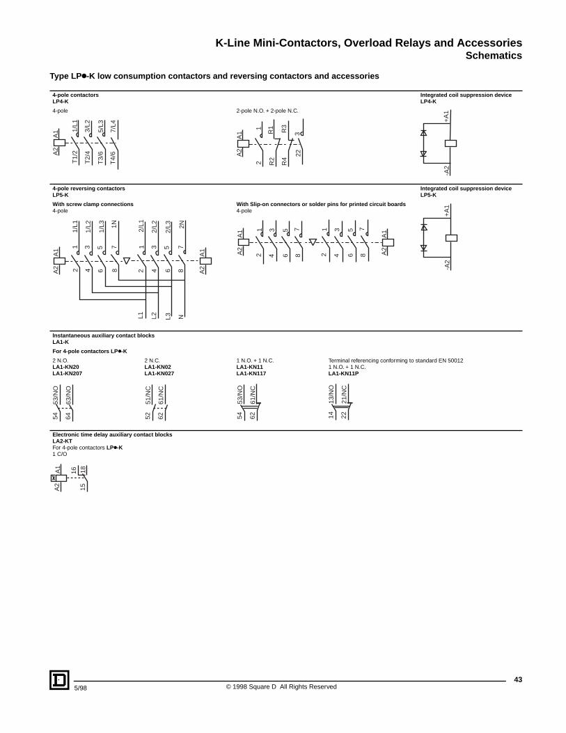
K-Line Mini-Contactors, Overload Relays and AccessoriesSchematics
435/98 © 1998 Square D All Rights Reserved
Type LPk-K low consumption contactors and reversing contactors and accessories
4-pole contactorsLP4-K
Integrated coil suppression deviceLP4-K
4-pole 2-pole N.O. + 2-pole N.C.
4-pole reversing contactors LP5-K
Integrated coil suppression device LP5-K
With screw clamp connections4-pole
With Slip-on connectors or solder pins for printed circuit boards4-pole
Instantaneous auxiliary contact blocksLA1-K
For 4-pole contactors LPk-K
2 N.O. LA1-KN20LA1-KN207
2 N.C. LA1-KN02LA1-KN027
1 N.O. + 1 N.C. LA1-KN11LA1-KN117
Terminal referencing conforming to standard EN 500121 N.O. + 1 N.C. LA1-KN11P
Electronic time delay auxiliary contact blocksLA2-KTFor 4-pole contactors LPk-K1 C/O
-A2
+A
1
A2
A1 1/
L1
3/L2
5/L3
7/L4
T1/
2
T2/
4
T3/
6
T4/
6 A2
A1
1
R1 R3
3
2 R2
R4
22
-A2
+A
1
A2
A1
1/L1
1/L2
1/L3 1N
2 4 6 8
2/L1
2/L2
2/L3 2N
2 4 6 8 A2
A1
L1 L2 L3 N
1 3 5 7 1 3 5 7
A2
A1 1 3 5 7
2 4 6 8 A2
A11 3 5 7
2 4 6 8
5453
/NO
6463
/NO
5251
/NC
6261
/NC
5453
/NO
6261
/NC
1413
/NO
2221
/NC
A2
A1
16 1815
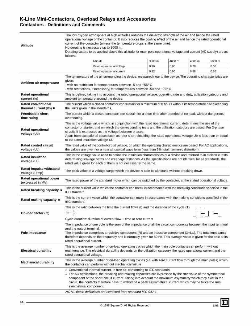
K-Line Mini-Contactors, Overload Relays and AccessoriesContactors - Definitions and Comments
© 1998 Square D All Rights Reserved44
5/98
Altitude
The low oxygen atmosphere at high altitudes reduces the dielectric strength of the air and hence the rated operational voltage of the contactor. It also reduces the cooling effect of the air and hence the rated operational current of the contactor (unless the temperature drops at the same time).No derating is necessary up to 3000 m.Derating factors to be applied above this altitude for main pole operational voltage and current (AC supply) are as follows.
Altitude 3500 m 4000 m 4500 m 5000 m
Rated operational voltage 0.90 0.80 0.70 0.60
Rated operational current 0.92 0.90 0.88 0.86
Ambient air temperature
The temperature of the air surrounding the device, measured near to the device. The operating characteristics are given:- with no restriction for temperatures between -5 and +55° C- with restrictions, if necessary, for temperatures between -50 and +70° C
Rated operational current (Ie)
This is defined taking into account the rated operational voltage, operating rate and duty, utilization category and ambient temperature around the device.
Rated conventional thermal current (Ith) c
The current which a closed contactor can sustain for a minimum of 8 hours without its temperature rise exceeding the limits given in the standards.
Permissible short time rating
The current which a closed contactor can sustain for a short time after a period of no load, without dangerous overheating.
Rated operational voltage (Ue)
This is the voltage value which, in conjunction with the rated operational current, determines the use of the contactor or starter, and on which the corresponding tests and the utilization category are based. For 3-phase circuits it is expressed as the voltage between phases.Apart from exceptional cases such as rotor short-circuiting, the rated operational voltage Ue is less than or equal to the rated insulation voltage Ui.
Rated control circuit voltage (Uc)
The rated value of the control circuit voltage, on which the operating characteristics are based. For AC applications, the values are given for a near sinusoidal wave form (less than 5% total harmonic distortion).
Rated insulation voltage (Ui)
This is the voltage value used to define the insulation characteristics of a device and referred to in dielectric tests determining leakage paths and creepage distances. As the specifications are not identical for all standards, the rated value given for each of them is not necessarily the same.
Rated impulse withstand voltage (Uimp)
The peak value of a voltage surge which the device is able to withstand without breaking down.
Rated operational power (expressed in kW)
The rated power of the standard motor which can be switched by the contactor, at the stated operational voltage.
Rated breaking capacity aThis is the current value which the contactor can break in accordance with the breaking conditions specified in the IEC standard.
Rated making capacity aThis is the current value which the contactor can make in accordance with the making conditions specified in the IEC standard.
On-load factor (m)
This is the ratio between the time the current flows (t) and the duration of the cycle (T)
Cycle duration: duration of current flow + time at zero current
Pole impedance
The impedance of one pole is the sum of the impedance of all the circuit components between the input terminal and the output terminal.The impedance comprises a resistive component (R) and an inductive component (X=Lω). The total impedance therefore depends on the frequency and is normally given for 50 Hz. This average value is given for the pole at its rated operational current.
Electrical durabilityThis is the average number of on-load operating cycles which the main pole contacts can perform without maintenance. The electrical durability depends on the utilization category, the rated operational current and the rated operational voltage.
Mechanical durabilityThis is the average number of on-load operating cycles (i.e. with zero current flow through the main poles) which the contactor can perform without mechanical failure
c Conventional thermal current, in free air, conforming to IEC standards.a For AC applications, the breaking and making capacities are expressed by the rms value of the symmetrical
component of the short-circuit current. Taking into account the maximum asymmetry which may exist in the circuit, the contacts therefore have to withstand a peak asymmetrical current which may be twice the rms symmetrical component.
NOTE: these definitions are extracted from standard IEC 947-1.
tm =T
t
T

K-Line Mini-Contactors, Overload Relays and Accessories
455/98 © 1998 Square D All Rights Reserved
K-Line Mini-Contactors, Overload Relays and Accessories
© 1998 Square D All Rights Reserved46
5/98
K-Line Mini-Contactors, Overload Relays and Accessories
475/98 © 1998 Square D All Rights Reserved

Catalog No. 8502CT9703 May 1998 © 1998 Square D All Rights Reserved.
Square D and are registered trademarks of Square D Company.Square D Company8001 Hwy. 64 EastKnightdale, NC 27545(919) 266-3671
and are registered trademarks of Underwriters Laboratories Inc.
is a registered trademarks of Canadian Standards Association.