Embed Size (px)
Citation preview

K-LEM KEMET Life Expectancy Model
Vincenzo Emanuele Caridà

K-LEM Developer Engineer
©KEMET Corporation. All Rights Reserved. 2
Vincenzo Emanuele Caridà
R&D New Product Engineer FILM BUSINESS UNIT SASSO MARCONI (BO) ITALY
Master Degree in Electrical Engineering - Bologna University in December ’17
Employed in KEMET in January ’18

Content
1. Introduction a) What is K-LEM b) Key Applications and Environmental Examples c) Film Capacitor Constructiond) Key Factors of Capacitance Degradation in Film Technology
2. K-LEM Features – Easy to Design-In
3. K-LEM Tool Development Processa) Boundaries Conditions and Testingb) Data Analysisc) Model Regressiond) Evaluation and Implementation
4. Film Capacitor Series available in K-LEM
What is K-LEM
K-LEM (KEMET Life Expectancy Model) is a powerful design tool, able to predictthe service life of KEMET Metallized Film Capacitors designed to withstand HarshEnvironmental conditions
It is the first tool in industry World, able to take into consideration three key factorsin the life of a capacitor: Temperature, Relative Humidity and Bias Voltage (THB)effects. It is based on a model developed at KEMET Corporation
The K-LEM (BETA V1.0) is available as a Film Life Calculator at our KEMETEngineering Center Web Site, and its full version will be part of our future DesignPlatform, K-SIM 3.0

Capacitor Life Expectancy
Product Lifetime Estimation is a Critical Design Factor for Different Applications and Enviromental Conditions
Applications Environments
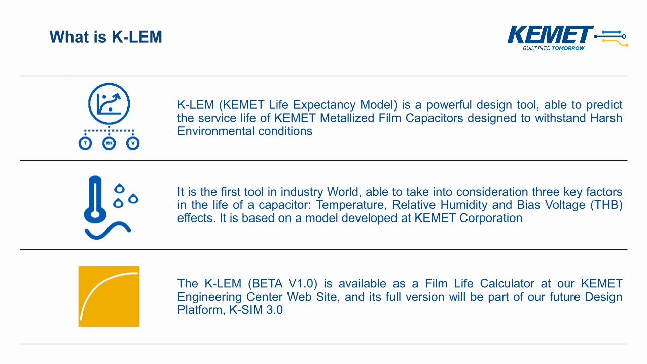
K-LEM helps to reduce unscheduled downtimesand service costs
Data Source: Moore, L.M. and H.N. Post, « Five years of operating experience at a large, utility-scale photovoltic generating palnt», Progress in Photovoltaics: Research and Applications
InverterTop Four Failures
Sub-SystemInverter
PV System
UnscheduledMaintenance
37% of Power Down Time
Loose Connection of Input and output connectors
Wear-out of theCapacitor Bank
54% of Service Cost
Varistor failure-short from the surge
Degradation of MosFET”s and diodes

Single-sided Metallized Polypropylene Film
OneSection
TwoSections
Film Capacitor basic construction concepts
𝑪𝑪 = 𝜺𝜺𝟎𝟎𝜺𝜺𝒓𝒓𝑨𝑨𝒅𝒅
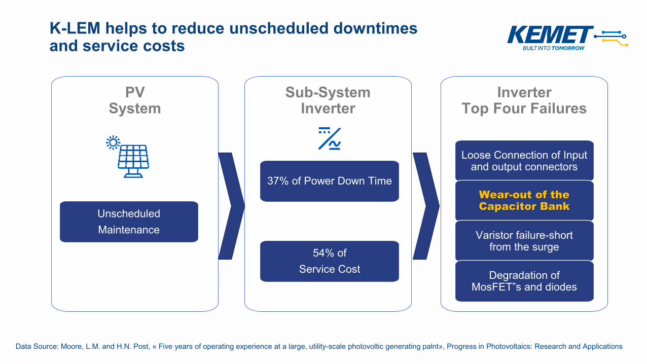
Self Healing
PartialDischarge
ElectrochemicalCorrosion
Self-Heating VAC & IAC50/60 Hz
ΔC/C negligible during normal application
(<< 1%)
ΔC/C occurs mainly at Low Temperature and Harsh Environment
Condition
ΔC/C is Proportional to Temperature,
Relative Humidity and Bias Voltage
ΔC/C and Lifetimeare Impacted by
Self-Heating
Capacitance Drop and Lifetime impacting factorsin Polypropylene Film Capacitors
K-LEM Considers The Three Main Capacitance Drop Causes

Film Capacitor Self Healing Property
Source: Maawad Makdessi, et al., «Metallized polymer film capacitors ageing law based on capacitance degradation”, Microelectronics Reliability, 2014
DefectMetallization
Dielectric Film
LocalizedBreakdown
Clearing of the Defected Zone
Metal VaporChemical By-Products
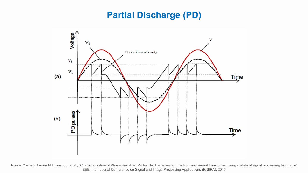
Partial Discharge (PD)
Source: Yasmin Hanum Md Thayoob, et al., “Characterization of Phase Resolved Partial Discharge waveforms from instrument transformer using statistical signal processing technique”,IEEE International Conference on Signal and Image Processing Applications (ICSIPA), 2015
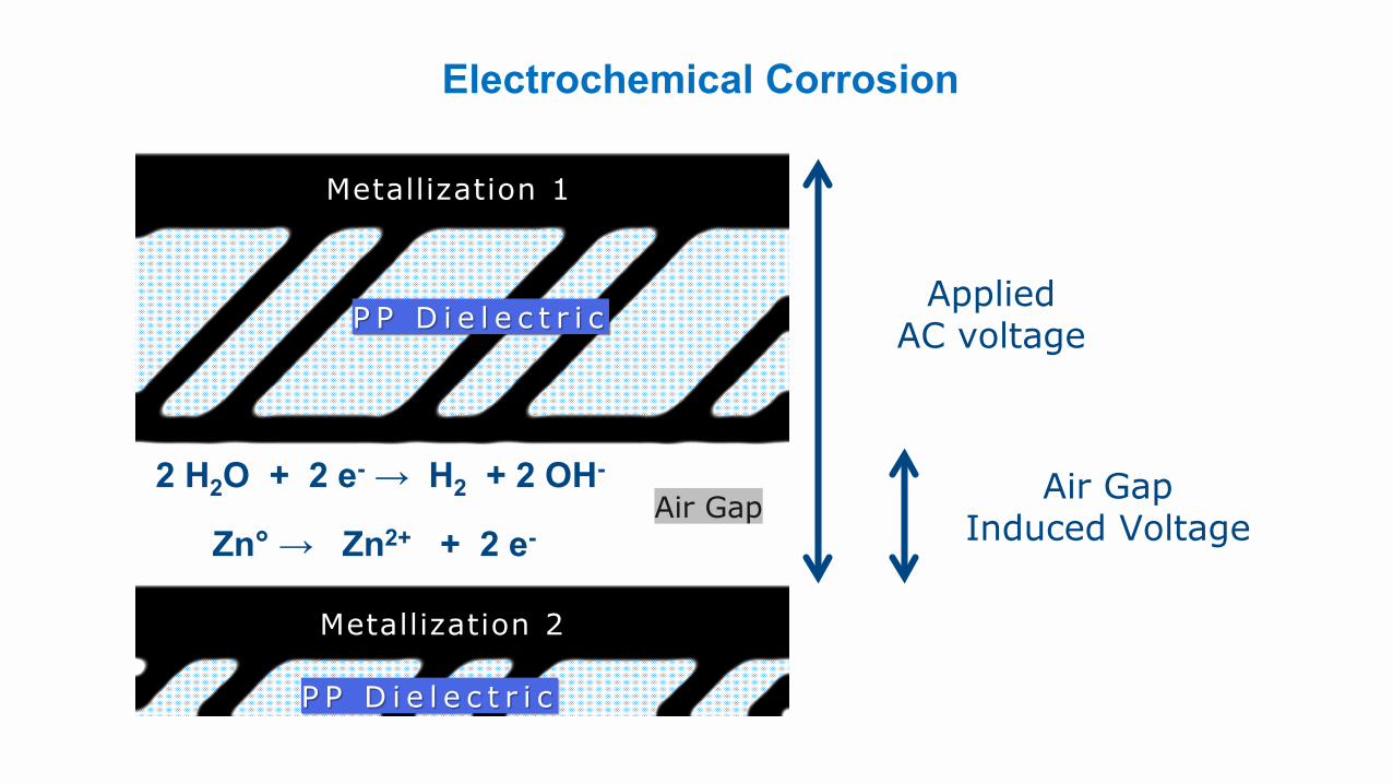
Electrochemical Corrosion
Metallization
Applied AC voltage
Air Gap Induced VoltageZn° → Zn2+ + 2 e-
2 H2O + 2 e- → H2 + 2 OH-
Metallization 2
P P D i e l e c t r i c
P P D i e l e c t r i c
Metallization 1
Air Gap

Self-Heating
∆𝑻𝑻𝑴𝑴𝑴𝑴𝑴𝑴= �𝒊𝒊=𝟏𝟏
𝟏𝟏=𝑵𝑵𝑰𝑰𝒓𝒓𝑰𝑰𝑰𝑰𝒊𝒊𝟐𝟐
𝟐𝟐𝝅𝝅𝒇𝒇𝒊𝒊𝑪𝑪× 𝒕𝒕𝒕𝒕𝒕𝒕𝑰𝑰𝑴𝑴𝑴𝑴(𝒇𝒇𝒊𝒊) × 𝑹𝑹𝒕𝒕𝒕𝒕

K-LEM Features
INPUT
Application Profiles
Temperature (°C)Relative Humidity (%)
AC Voltage (V)
OUTPUT
Operational Expected Life
Hours & YearsEnd of Life
Criteria (ΔC/C: -20 %)
Easy To Design-in Tool

3 ) M o d e l R e g r e s s i o n
4 ) R e g r e s s i o n C o n d i t i o n C h e c k i n g
1 ) B o u n d a r i e s C o n d i t i o n &
E l e c t r i c a l Te s t i n g
2 ) D a t a A n a l y s i s & M o d e l
D e f i n i t i o nK-LEM
Implementation of K-LEM Application

1) Boundaries Conditions & Electrical Testing
Boundaries Conditions Electrical Testing
• Definition of failure with end of life criteria of the capacitors
• Reliability Level %
• Confidence Level %
• Stress Conditions
• Characterization of the capacitors under test
• Observing the same failure mechanism
• Improve the Model Regression
• Extended tests for accurate data (>1 year)
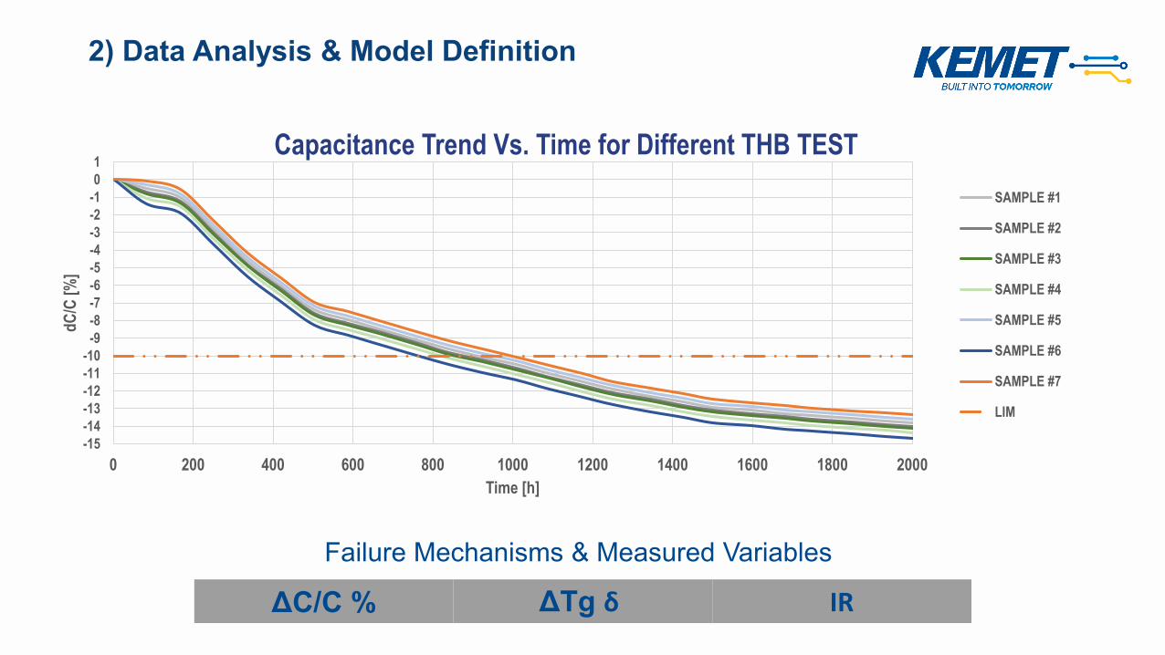
2) Data Analysis & Model Definition
Failure Mechanisms & Measured Variables
ΔC/C % ΔTg δ IR
-15-14-13-12-11-10-9-8-7-6-5-4-3-2-101
0 200 400 600 800 1000 1200 1400 1600 1800 2000
dC/C
[%]
Time [h]
Capacitance Trend Vs. Time for Different THB TESTSAMPLE #1
SAMPLE #2
SAMPLE #3
SAMPLE #4
SAMPLE #5
SAMPLE #6
SAMPLE #7
LIM
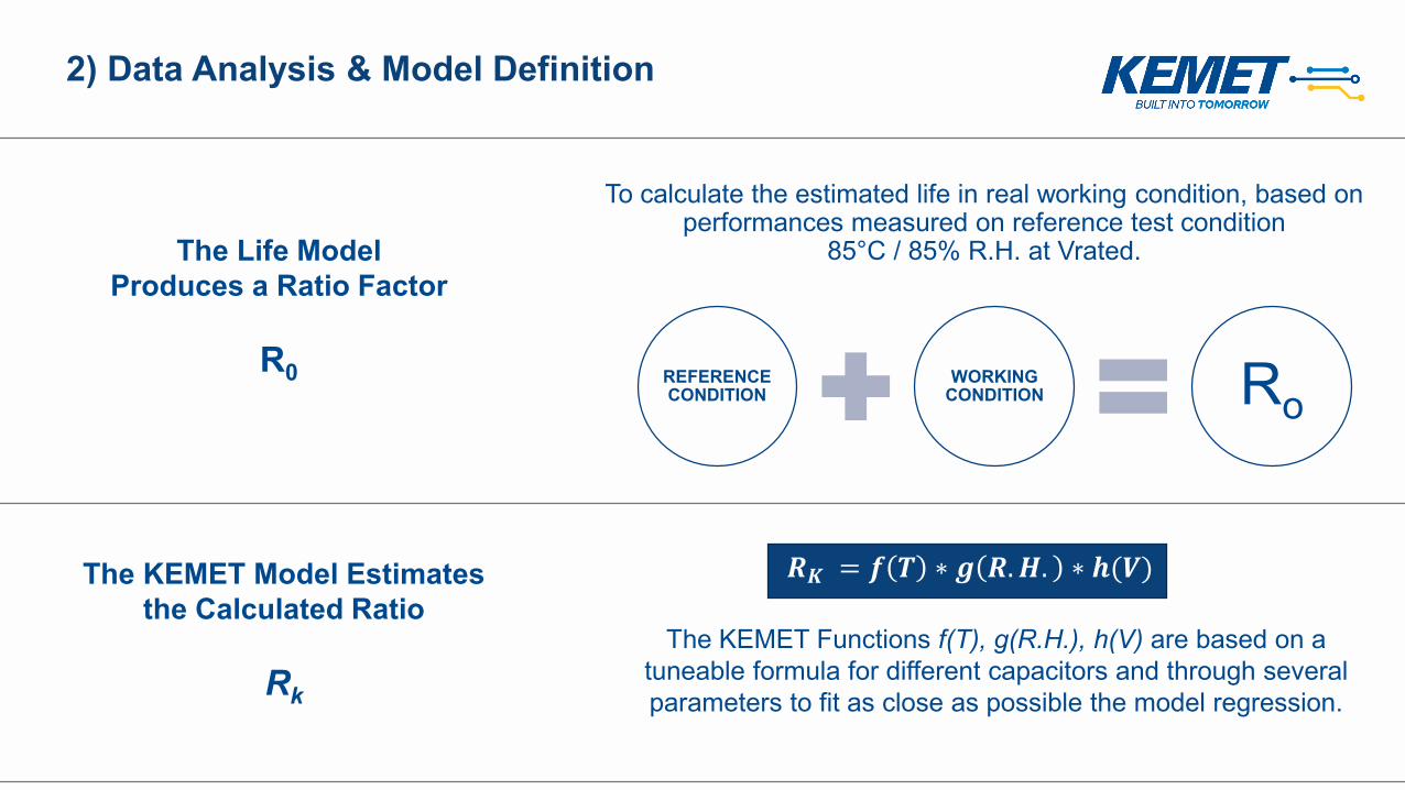
2) Data Analysis & Model Definition
To calculate the estimated life in real working condition, based on performances measured on reference test condition
85°C / 85% R.H. at Vrated.
REFERENCE CONDITION
WORKING CONDITION Ro
𝑹𝑹𝑲𝑲 = 𝒇𝒇 𝑻𝑻 ∗ 𝒕𝒕 𝑹𝑹.𝑯𝑯. ∗ 𝒕𝒕(𝑽𝑽)
The KEMET Functions f(T), g(R.H.), h(V) are based on a tuneable formula for different capacitors and through several parameters to fit as close as possible the model regression.
The Life Model Produces a Ratio Factor
R0
The KEMET Model Estimates the Calculated Ratio
Rk

3) Model Regression
𝑅𝑅𝑂𝑂 ≈ 𝑎𝑎 + 𝑏𝑏 � 𝑅𝑅𝐾𝐾b: regression slope a: regression intercept
FACTOR Ro
REFERENCE CONDITION
WORKING CONDITION
FACTOR Rk
REFERENCE CONDITION
WORKING CONDITION
KEMET THB Model Experimental Data

4) Model Performance
1050-5
99
95
90
807060504030
20
10
5
1
Residual
Perce
nt
Normal Probability Plot(response is Ro)
7,55,02,50,0-2,5-5,0
7
6
5
4
3
2
1
0
Residual
Frequ
ency
Histogram(response is Ro)
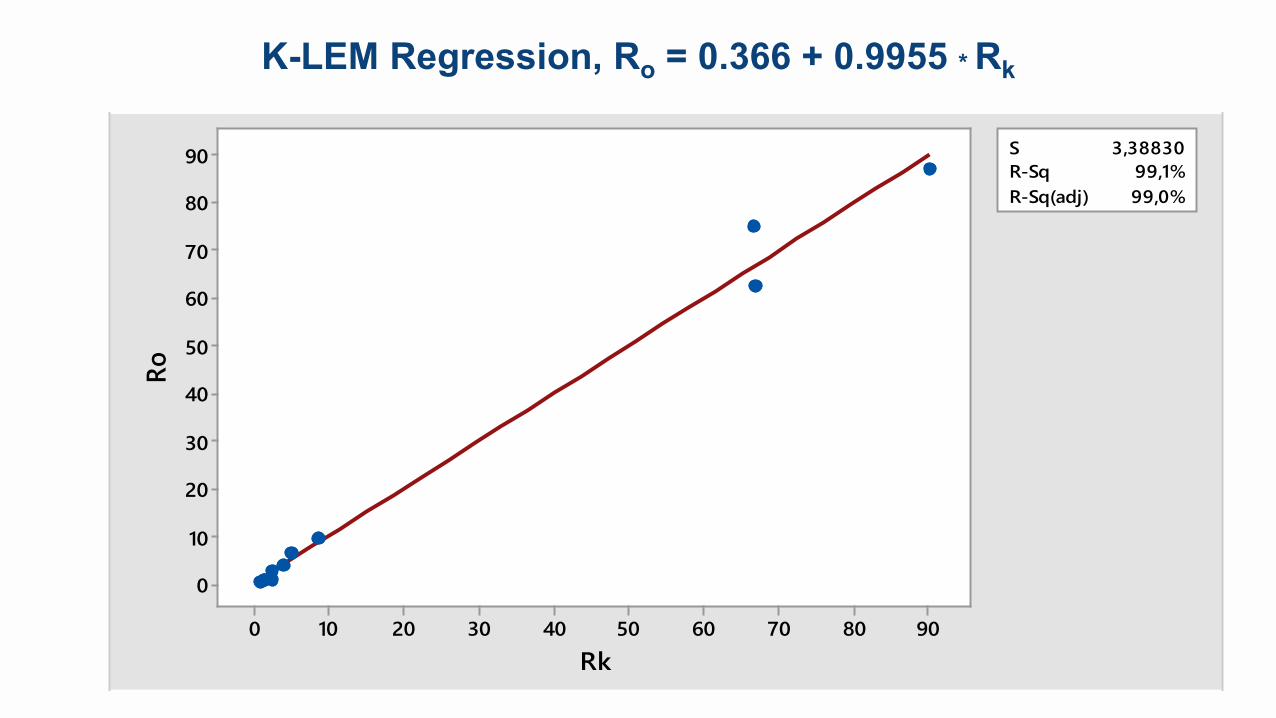
K-LEM Regression, Ro = 0.366 + 0.9955 * Rk
9080706050403020100
90
80
70
60
50
40
30
20
10
0
S 3,38830R-Sq 99,1%R-Sq(adj) 99,0%
Rk
Ro
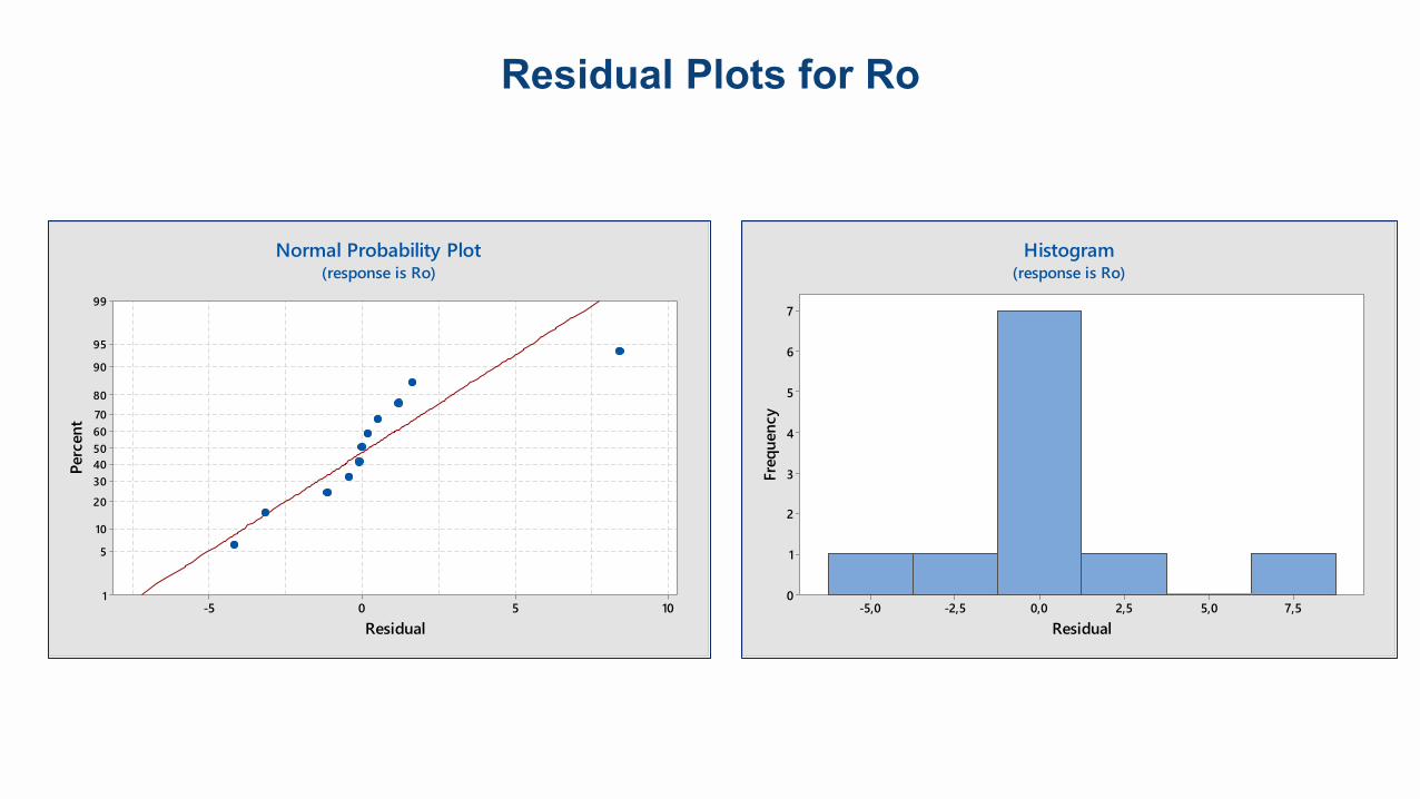
Residual Plots for Ro
1050-5
99
95
90
807060504030
20
10
5
1
Residual
Perc
ent
Normal Probability Plot(response is Ro)
7,55,02,50,0-2,5-5,0
7
6
5
4
3
2
1
0
Residual
Freq
uenc
y
Histogram(response is Ro)

4) Model Performance
• Coefficient of determination: Rsq > 90 %
• Linearity: b ≈1
• Residual Standard Deviation: S<4
• Confidence Level = 95%
• Residual Normally Distributed

Probability Plot of Residual. Normal; 95% of CI
1050-5-10
99
95
90
807060504030
20
10
5
1
Mean -0,06727StDev 2,858N 11AD 0,588P-Value 0,096
RESIDUAL
Perc
ent

1 10 20 30 40 50 60 70 80 90 100 110
010,00020,00030,00040,00050,00060,00070,00080,00090,000100,000110,000120,000130,000140,000150,000
17.5
1522.5
3037.5
4552.5
6067.5
7582.5
9097.5
Temperature [°C]
Rela
tive
Hum
idity
[%]
140,000-150,000
130,000-140,000
120,000-130,000
110,000-120,000
100,000-110,000
90,000-100,000
80,000-90,000
70,000-80,000
60,000-70,000
50,000-60,000
40,000-50,000
30,000-40,000
20,000-30,000
10,000-20,000
0-10,000
4) Real Case: F862 X2 EMI Capacitor 310 VAC
Lifetime Expectancy (hrs.) @ 240 Vac
F862FY475310K-V054
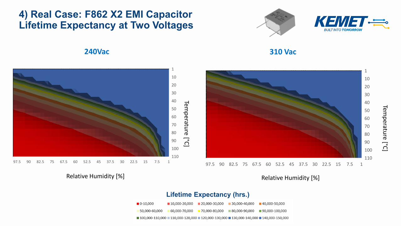
4) Real Case: F862 X2 EMI CapacitorLifetime Expectancy at Two Voltages
Lifetime Expectancy (hrs.)
1
10
20
30
40
50
60
70
80
90
100
11017.51522.53037.54552.56067.57582.59097.5
Temperature [°C]
Relative Humidity [%]
240Vac
1102030405060708090100110
17.51522.53037.54552.56067.57582.59097.5
Temperature [°C]
Relative Humidity [%]
310 Vac
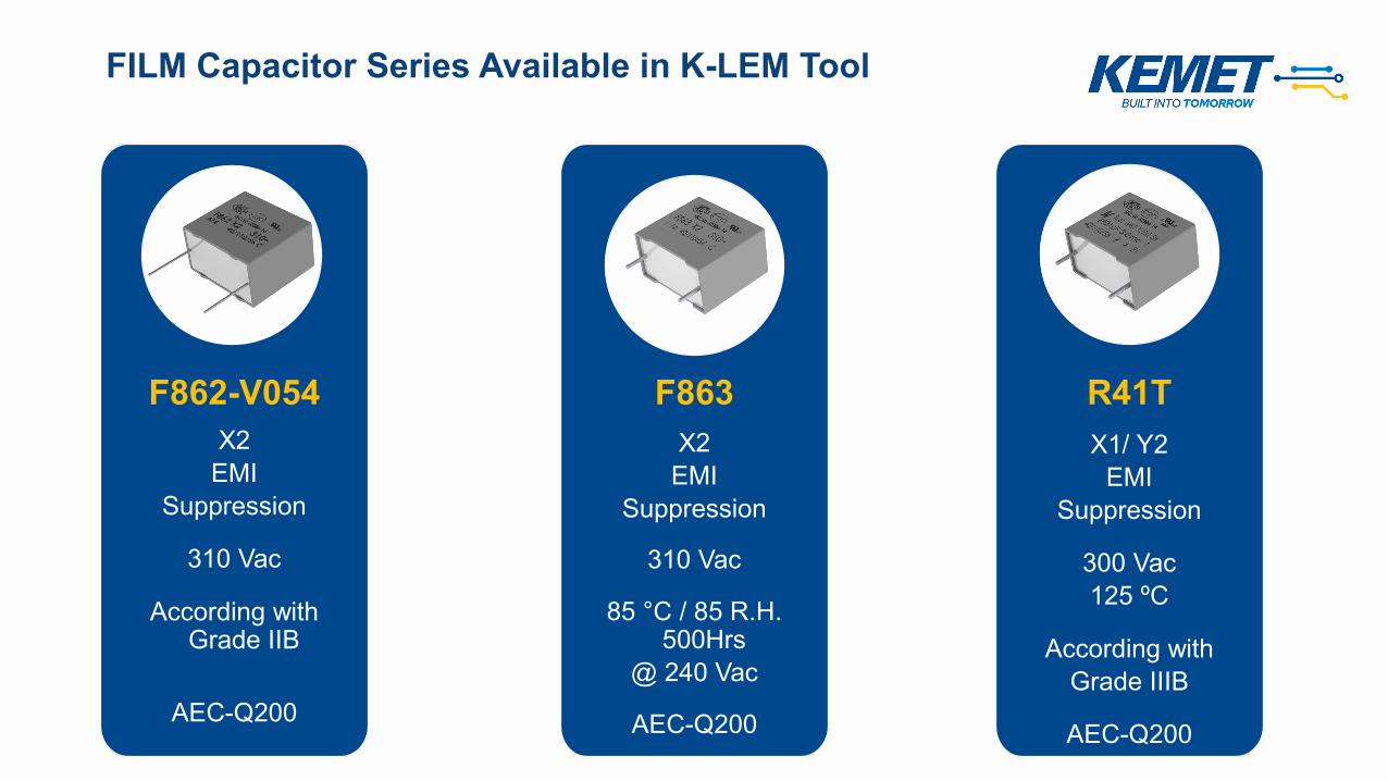
K-LEM WEB TOOLFILM Capacitor Series Available in K-LEM Tool
F862-V054X2
EMI Suppression
310 Vac
According with Grade IIB
AEC-Q200
F863X2
EMISuppression
310 Vac
85 °C / 85 R.H. 500Hrs
@ 240 Vac
AEC-Q200
R41TX1/ Y2
EMI Suppression
300 Vac125 ºC
According withGrade IIIB
AEC-Q200
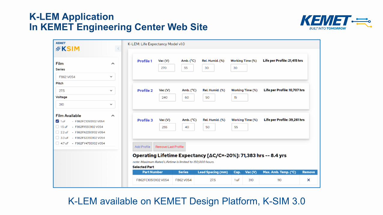
K-LEM Application In KEMET Engineering Center Web Site
K-LEM available on KEMET Design Platform, K-SIM 3.0

EMI Suppressors
X & Y Safety
Capacitors
THB High Capabilities
AC & DC Power Box
DC-Link &
AC Filter
THBHigh Capabilities
K-LEM WEB TOOLK-LEM Web Tool For Future THB Film Series
All the coming Film Series with Temperature, Humidity Bias (THB)
capability will be available on K-LEM Model