Embed Size (px)
Citation preview

Kickbot: A Spherical Autonomous Robot
Christopher Batten and David Wentzla!6.836 Final Project
{cbatten|wentzlaf}@mit.edu
1 Introduction
Kickbot is a custom built autonomous robotwhich wanders in its environment searching forpeople who will kick it. Kickbot’s novel spheri-cal body and solid construction make it ideal forkicking, and its carefully counterweighted cen-tral disk helps stabilize the robot after tumbling.Kickbot has a two part distributed control sys-tem which uses various sensors to avoid obsta-cles, detect when it is being kicked, and find peo-ple to antagonize.
There were three main objectives we hoped toachieve by building Kickbot. First, we wanted tobuild an autonomous robot from scratch. Too of-ten it seems that building a robot simply meansobtaining a pre-made robot control board, at-taching a few sensors and four wheels, and thenprogramming it to move around. We lacked thefinancial means to purchase a commercial controlboard with an advanced embedded microproces-sor, but more importantly we wanted the experi-ence of creating our own control system and ex-perimenting with our own ideas for an interestingrobot body. Part of what makes robotics so ex-citing is that it includes so many varied aspects:mechanical, electrical, behavioral, and control.
The second objective for building Kickbot ismore specific. Most robots have strict orienta-tion requirements such that they will not func-tion correctly, if at all, when turned upside downor placed on their side. We wanted to create arobot where falling over was not a failure mode.Kickbot is specifically designed to correctly ori-ent itself when knocked over or after bouncinginto an obstacle. The third objective was to ex-periment with various emergent behaviors witha robot that we built ourselves. We were ableto observe Kickbot exhibiting several interesting
Figure 1: View of Kickbot
behaviors: both expected and unexpected.
Overall, the project was a success. Kickbot isable to roll around an o!ce building and avoidobstacles. Due to the specifics of its sensor place-ment, sometimes Kickbot does not see an obsta-cle and so it rolls into it, but Kickbot doesn’tmind. It simply bounces o" in a new direction.Kickbot can detect motion and rolls towards itin an attempt to find someone to kick it. Whenkicked it lets itself tumble, and when stable againKickbot wanders o" once more. But the ex-perience we gained building Kickbot is just asimportant as the final robot itself. We learnedhow to machine our own parts, program a micro-controller, and build a robot body out of a ham-ster ball and some styrofoam. We learned theimportance of decoupling capacitors, that thingscan and will break, and that sensors are perfectlyhappy to lie for no good reason. Ultimately,however, we learned that building a robot fromscratch is great fun.
1

Mercury Switch
IR Sensor
(camera-backward)
(1)
(2)
Mercury Switch
D (1bit)
D (1bit)
H-bridgeH-bridge
(L) (R)
Dir
- D
(1
bit
)
Mag
- P
WM
Brk
- D
(1
bit
)
(L) (R)
Motor Motor
A (0.5v to 3v)
A (0.5v to 3v)
A (
-12
v t
o 1
2v
)
A (
-12
v t
o 1
2v
)
Board
Camera Control
RS232IR Sensor
Main Control
Board
Dir
- D
(1
bit
)
Brk
- D
(1
bit
)
Gameboy
Camera
Mag
- P
WM
(camera-forward)
Rea
d -
D (
1b
it)
A (
1.5
v t
o 4
v)
Clk
- D
(1
bit
)
Ctr
l -
D (
3b
it)
Figure 2: System-Level Block Diagram - Arrows indicate connectivity and format of communication betweenblocks. A = analog, D = digital, PWM = pulse width modulation.
1.1 System Overview
Kickbot is composed of two plastic half-spheres and a central disk (see Figure 1). Thecentral disk contains all of the electronics, sen-sors, and motors and is attached to the half-spheres through an aluminum hub and sixspokes. The central disk also includes signif-icant counterweight to help stabilize the robotand permit forward motion.
Figure 2 is a system-level block diagram ofthe robot. The connectivity arrows also indicatethe actual communication format: A indicatesan analog signal and associated voltage range,D indicates a digital signal and associated num-ber of bits, and PWM indicates a pulse widthmodulated signal. Kickbot has several sensors:two infrared range sensors mounted in oppositedirections, two mercury switches to monitor ori-entation, and a small camera. There are two cus-tom built control boards: a main control boardand a camera control board. Each board has itsown micro-controller and some additional logic
(e.g. SRAMs, LEDs, dip switches). The maincontrol board is responsible for monitoring theIR sensors and the two mercury switches, andalso controls the two H-bridges which in turncontrol the two drive motors. The camera con-trol board is responsible for operating the cameraand image processing. Communication betweenthe two control boards is through the standardRS232 protocol.
1.2 Outline
The remaining sections of this report will pro-vide more details concerning the constructionand operation of Kickbot. Section 2 discussesKickbot’s high-level behaviors within the con-text of a subsumption architecture. Section 3concentrates on the mechanical aspects of Kick-bot, while Sections 4 and 5 discuss the electricaland control aspects of the main control boardand the camera board. Section 6 presents somefinal conclusions.
2
Board
SS
Control
Control
Board
Main
Camera
Wander
Antagonize
Camera
Motors
Motion
Detect
Mercury
SensorsTumble
IR Sensors
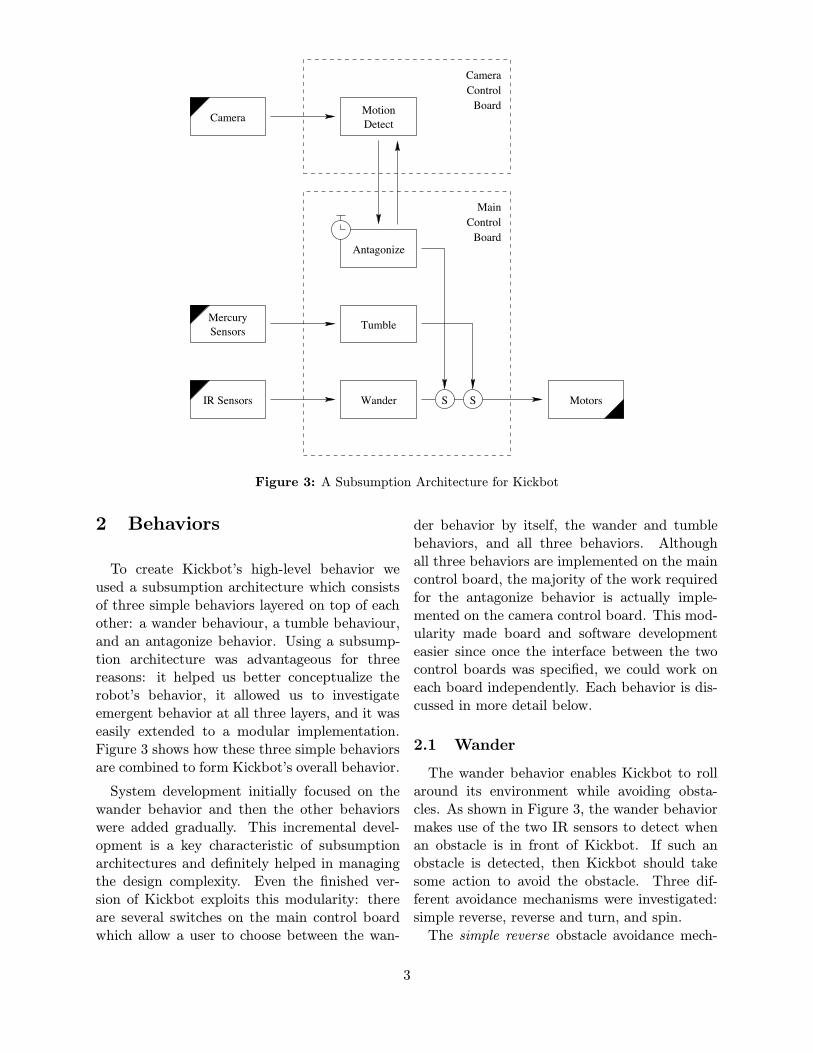
Figure 3: A Subsumption Architecture for Kickbot
2 Behaviors
To create Kickbot’s high-level behavior weused a subsumption architecture which consistsof three simple behaviors layered on top of eachother: a wander behaviour, a tumble behaviour,and an antagonize behavior. Using a subsump-tion architecture was advantageous for threereasons: it helped us better conceptualize therobot’s behavior, it allowed us to investigateemergent behavior at all three layers, and it waseasily extended to a modular implementation.Figure 3 shows how these three simple behaviorsare combined to form Kickbot’s overall behavior.
System development initially focused on thewander behavior and then the other behaviorswere added gradually. This incremental devel-opment is a key characteristic of subsumptionarchitectures and definitely helped in managingthe design complexity. Even the finished ver-sion of Kickbot exploits this modularity: thereare several switches on the main control boardwhich allow a user to choose between the wan-
der behavior by itself, the wander and tumblebehaviors, and all three behaviors. Althoughall three behaviors are implemented on the maincontrol board, the majority of the work requiredfor the antagonize behavior is actually imple-mented on the camera control board. This mod-ularity made board and software developmenteasier since once the interface between the twocontrol boards was specified, we could work oneach board independently. Each behavior is dis-cussed in more detail below.
2.1 Wander
The wander behavior enables Kickbot to rollaround its environment while avoiding obsta-cles. As shown in Figure 3, the wander behaviormakes use of the two IR sensors to detect whenan obstacle is in front of Kickbot. If such anobstacle is detected, then Kickbot should takesome action to avoid the obstacle. Three dif-ferent avoidance mechanisms were investigated:simple reverse, reverse and turn, and spin.The simple reverse obstacle avoidance mech-
3
anism was actually an emergent behavior. Anearly version of Kickbot had very little counter-weight and was programmed to simply reversedirections when an obstacle was detected. Itwas expected that Kickbot would move back andforth between two obstacles. Kickbot’s actualbehavior was much more interesting and a primeexample of emergence. Kickbot would see anobstacle and stop its motors, but because of thelimited counter-weight, it would continue to rollinto the obstacle. Kickbot would then bounce inan arbitrary direction and begin moving. Therandomness of a complex environment allowedKickbot to wander without any explicit turningmechanism.Although the simple reverse technique was in-
teresting, it was di!cult to control and numerouscollisions were straining the robot. The reverseand turn obstacle avoidance mechanism relies onan increased counter-weight to help Kickbot stopbefore colliding with the detected obstacle. SinceKickbot is symmetrical, it just moves in the op-posite direction without needing to actually turncompletely around. One of the motors startsin the reverse direction before the other motor,which causes Kickbot to turn slightly and heado" in a new direction. The amount that Kickbotturns varies based on how charged the batteriesare and the surface that Kickbot is moving on.Kickbot’s small wheel base means that it turnsmuch better on smoother surfaces such as tile.When moving on carpet, Kickbot turns signifi-cantly less if at all. This is a good example ofsituatedness, and it has consequences on Kick-bot’s overall behavior: Kickbot tends to exploremore when moving on smoother surfaces thanwhen moving on rougher surfaces.The spin obstacle avoidance mechanism pre-
vents Kickbot from becoming trapped betweentwo obstacles. It was expected that Kickbotwould never move into a situation where an ob-stacle was both in front and behind it, since thereverse and turn mechanism should enable Kick-bot to avoid the obstacle completely. But therandomness and complexity of Kickbot’s envi-ronment created several situations where it be-came trapped. To address this, the spin obsta-cle avoidance mechanism causes Kickbot to spinin place for some amount of time if an obstacle
is detected both in front and behind. Kickbotthen stops and checks to see if either direction isclear. If so, Kickbot proceeds in that direction,otherwise it spins again. This behavior signifi-cantly reduced the number of times Kickbot be-came trapped, but it also revealed another un-expected emergent behavior. Sometimes Kick-bot goes over a small bump and the central diskaccidently swings causing the forward IR sensorto point down. Kickbot sees the floor, thinksthere is an obstacle, and stops quickly. If Kick-bot is moving fast enough, this can cause Kick-bot to swing in the opposite direction and theopposite IR sensors also sees the floor. Kickbotthinks it is trapped and spins in place. The re-sult is that Kickbot occasionally spins in placeand heads in a new direction even if no obsta-cles are nearby. This slight randomness causesKickbot to explore in many new directions thatit would otherwise miss if it always moved in astraight line.
2.2 Tumble
If Kickbot is kicked with just the wander be-havior, its motors will spin wildly and Kickbotwill not roll very far. The tumble behavior usesthe two mercury switches to sense when Kickbotis being kicked, and then suppresses all motormessages with stop messages (as shown in Fig-ure 3). This allows Kickbot to roll much morecleanly after being kicked and enables it to waitfor a period time to make sure it has fully sta-bilized before continuing. From the observer’sperspective, this stabilization period may makeKickbot appear to be catching its breath aftertumbling before moving on.
2.3 Antagonize
The antagonize behavior can be layered on topof the wander and tumble behaviors to aid Kick-bot in finding people to kick it. This behaviorallows Kickbot to periodically stop and turn in acircle looking for movement using the camera.If it detects movement, Kickbot rolls towardsthe movement and bumps into the moving ob-ject. Kickbot tries to annoy the moving objectso that it will be kicked. Figure 3 shows how
4
a timer on the main control board signals whenKickbot should start looking for movement. Thecamera control board handles all communicationwith the camera and does the necessary imageprocessing to determine if there is movement inthe field of view. The camera control board canalso calculate if this movement is directly ahead,to the left, or to the right, and the main controlboard can use this information to turn slightlytowards the movement.
The antagonize behavior is not a movementfollowing behavior since Kickbot only looks formovement occasionally and must stop beforecapturing any images. Instead, the antagonizebehavior enables Kickbot to focus more on ar-eas in his environment where there is movement.This means Kickbot will have a better chance offinding a person to kick it.
3 Mechanical Design
Kickbot’s mechanical design was primarily in-fluenced by two key design constraints: fallingover should not be a failure mode and Kickbotshould be able to be kicked. To a lesser extent,finacial constraints also influenced Kickbot’s me-chanical design.
In the early days of the Kickbot design, Kick-bot was going to be a cube with six symmetricdrive sides. But unfortunately (or fortunately),we realized that having so many sides and drivemechanisms was prohibitively expensive. Toovercome this problem while maintaining therobot’s robustness to falling over, Kickbot wasredesigned as a sphere. This novel spherical de-sign consists of three parts: two half-spheres anda central disk. The two half-spheres rotate andthe central disk provides a place to mount sen-sors and other electronics. The central disk iskept stable and upright with a counterweight onone-half of the central disk. The counterweightmakes forward motion possible and helps reori-ent Kickbot when it is tumbling. For locomotion,Kickbot has two motors mounted on the centraldisk. Each motor is attached to one half-sphereand this provides a basic form of di"erential drivecontrol.
3.1 Physics
To understand the physics of Kickbot, let’sfirst assume that Kickbot’s half-spheres are actu-ally two large circular wheels attached to a cen-tral disk. Now let’s assume that the wheels andcentral disk are equally weighted. Depending onthe balance of rotational moment of inertia of thecentral disk, the rolling friction that the wheelsexperience with the floor, and the rotational mo-ment of inertia of the wheels, the central diskwould probably start to spin in the center of therobot and possibly some small forward locomo-tion would occur. But what if we increase theweight of the central disk?
If the mass of the central disk is increasedevenly across its volume, then this would in-crease the rotational moment of inertia of thecentral disk. A heavier central disk increases itsresistance to rotation and makes the outer half-spheres rotate more. The result is forward mo-tion.
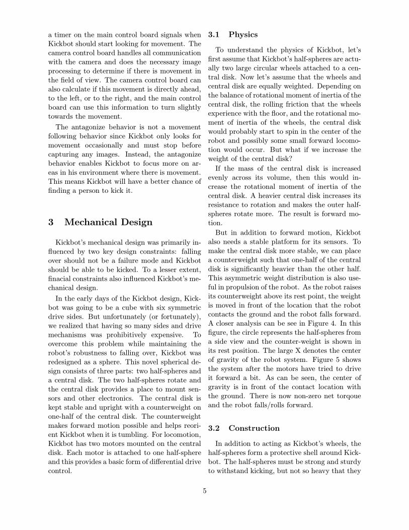
But in addition to forward motion, Kickbotalso needs a stable platform for its sensors. Tomake the central disk more stable, we can placea counterweight such that one-half of the centraldisk is significantly heavier than the other half.This asymmetric weight distribution is also use-ful in propulsion of the robot. As the robot raisesits counterweight above its rest point, the weightis moved in front of the location that the robotcontacts the ground and the robot falls forward.A closer analysis can be see in Figure 4. In thisfigure, the circle represents the half-spheres froma side view and the counter-weight is shown inits rest position. The large X denotes the centerof gravity of the robot system. Figure 5 showsthe system after the motors have tried to driveit forward a bit. As can be seen, the center ofgravity is in front of the contact location withthe ground. There is now non-zero net torqoueand the robot falls/rolls forward.
3.2 Construction
In addition to acting as Kickbot’s wheels, thehalf-spheres form a protective shell around Kick-bot. The half-spheres must be strong and sturdyto withstand kicking, but not so heavy that they
5
weight
counter
contact with ground
Figure 4: Kickbot in Rest State
weightcounter
contact with ground
Figure 5: Kickbot Falling Forward
outweigh the central disk. We found the perfectsolution at our local pet store: an 11 inch diam-eter hamster ball. Hamster balls are made outof a flexible yet durable plastic. This flexibilityturned out to be very useful, since it acted as asimple shock absorber during collisions.
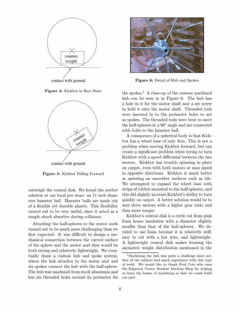
Attaching the half-spheres to the motor axelsturned out to be much more challenging than wefirst expected. It was di!cult to design a me-chanical connection between the curved surfaceof the sphere and the motor axel that would beboth strong and relatively lightweight. We even-tually chose a custom hub and spoke system,where the hub attaches to the motor axel andsix spokes connect the hub with the half-sphere.The hub was machined from stock aluminum andhas six threaded holes around its perimeter for
Figure 6: Detail of Hub and Spokes
the spokes.1 A close-up of the custom machinedhub can be seen in in Figure 6. The hub hasa hole in it for the motor shaft and a set screwto hold it onto the motor shaft. Threaded rodswere inserted in to the perimeter holes to actas spokes. The threaded rods were bent to meetthe half-spheres at a 90! angle and are connectedwith bolts to the hamster ball.A consquence of a spherical body is that Kick-bot has a wheel base of only 3cm. This is not aproblem when moving Kickbot forward, but cancreate a significant problem when trying to turnKickbot with a speed di"erntial between the twomotors. Kickbot has trouble spinning in placeon carpet, even with both motors at max speedin opposite directions. Kickbot is much betterat spinning on smoother surfaces such as tile.We attempted to expand the wheel base withstrips of rubber mounted to the half-spheres, andthis did slightly increase Kickbot’s ability to turnquickly on carpet. A better solution would be touser drive motors with a higher gear ratio andthus more torque.Kickbot’s central disk is a circle cut from pinkfoam house insulation with a diameter slightlysmaller than that of the half-spheres. We de-cided to use foam because it is relatively sti",easy to cut with a hot wire, and lightweight.A lightweight central disk makes forming theasymetric weight distribution mentioned in the
1Machining the hub was quite a challenge since nei-ther of the authors had much experience with this typeof work. We would like to thank Fred Cote who runsthe Edgerton Center Student Machine Shop for helpingus learn the basics of machining so that we could buildour part.
6
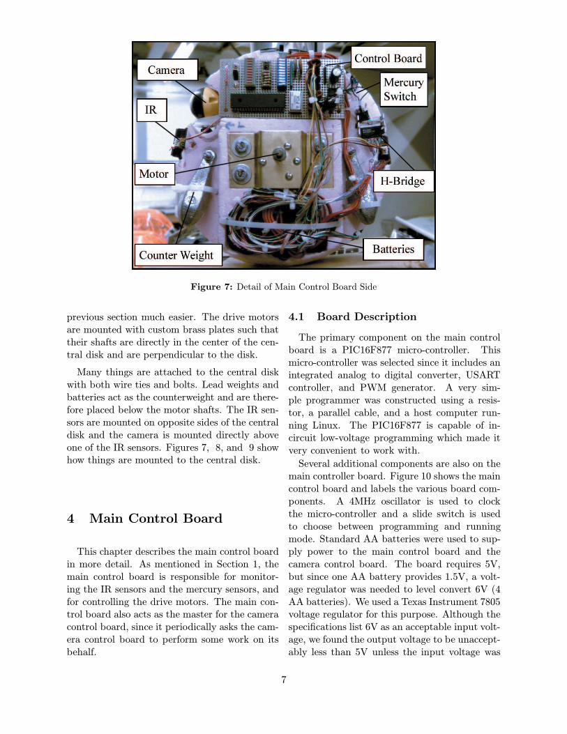
Figure 7: Detail of Main Control Board Side
previous section much easier. The drive motorsare mounted with custom brass plates such thattheir shafts are directly in the center of the cen-tral disk and are perpendicular to the disk.
Many things are attached to the central diskwith both wire ties and bolts. Lead weights andbatteries act as the counterweight and are there-fore placed below the motor shafts. The IR sen-sors are mounted on opposite sides of the centraldisk and the camera is mounted directly aboveone of the IR sensors. Figures 7, 8, and 9 showhow things are mounted to the central disk.
4 Main Control Board
This chapter describes the main control boardin more detail. As mentioned in Section 1, themain control board is responsible for monitor-ing the IR sensors and the mercury sensors, andfor controlling the drive motors. The main con-trol board also acts as the master for the cameracontrol board, since it periodically asks the cam-era control board to perform some work on itsbehalf.
4.1 Board Description
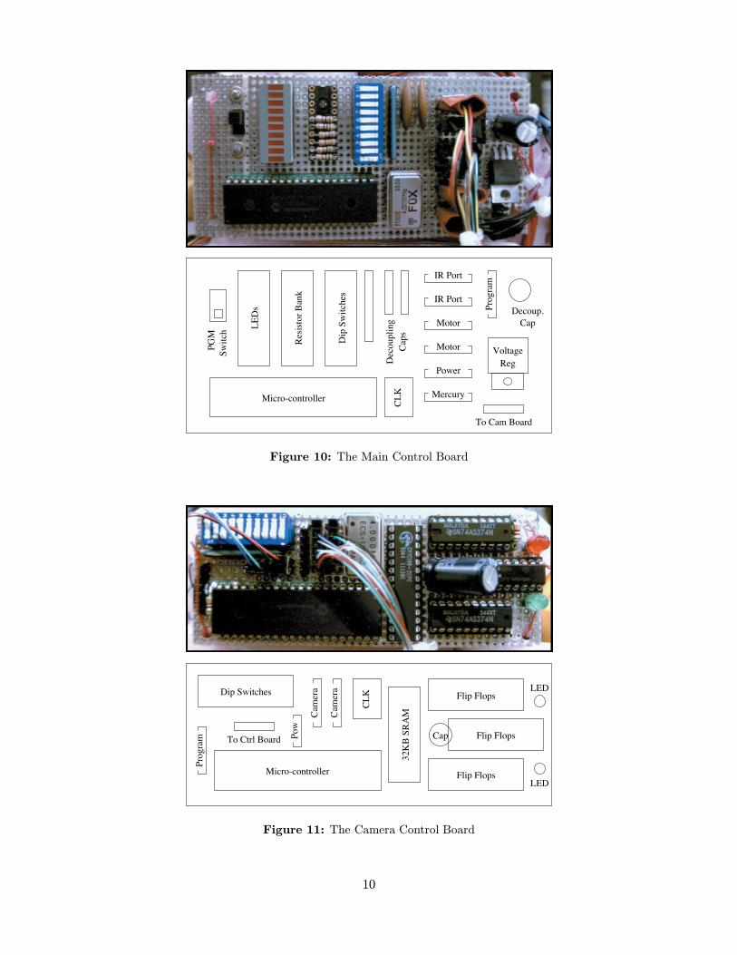
The primary component on the main controlboard is a PIC16F877 micro-controller. Thismicro-controller was selected since it includes anintegrated analog to digital converter, USARTcontroller, and PWM generator. A very sim-ple programmer was constructed using a resis-tor, a parallel cable, and a host computer run-ning Linux. The PIC16F877 is capable of in-circuit low-voltage programming which made itvery convenient to work with.Several additional components are also on themain controller board. Figure 10 shows the maincontrol board and labels the various board com-ponents. A 4MHz oscillator is used to clockthe micro-controller and a slide switch is usedto choose between programming and runningmode. Standard AA batteries were used to sup-ply power to the main control board and thecamera control board. The board requires 5V,but since one AA battery provides 1.5V, a volt-age regulator was needed to level convert 6V (4AA batteries). We used a Texas Instrument 7805voltage regulator for this purpose. Although thespecifications list 6V as an acceptable input volt-age, we found the output voltage to be unaccept-ably less than 5V unless the input voltage was
7

Figure 8: Detail of Camera Control Board Side
Figure 9: Detail of Front
8
set to 8V or more. We therefore added two moreAA batteries to bring the total number of AAbatteries supplying the controller boards to six.Note that the drive motors use a completely dif-ferent set of AA batteries to avoid current spikeswhen the motors switch directions or encounterresistance.A set of ten LEDs provide a way for the micro-
controller to visually display status information.The current version of the main controller boardsoftware uses one LED to indicate when therobot is in tumbling mode, and a second LED toindicate when the robot is in antagonize mode.The remaining eight LEDs are used to displaythe input from the currently active IR sensors.Six dip switches are available for configuration.The current software version uses one of theseswitches as a board enable, a second switch toenable the tumbling behavior, and a third switchto enable the antagonize behavior.The main controller board includes nine ports:
one 4 pin port for power, two 4 pin input portsfor the IR sensors, two 2 pin input ports for themercury switches, two 4 pin output ports for themotor control, one 5 pin input port for the pro-grammer, and one 4 pin port for the interface tothe camera control board. We chose to use SharpGP2D12 infrared detectors which claim a rangeof 80cm, although our testing found the range tobe closer to 60cm. These IR sensors are wired tothe A/D inputs on the micro-controller. An ex-ternal voltage divider is used to provide a voltagereference of 3v to the A/D converter, since theIR sensor output is only 0.5v to 3v. The mer-cury switches and motor control bits are wiredto the digital I/O pins on the micro-controller.The mercury switches are mounted at oppositeangles such that both switches will be on only ifthe robot is not more than 90! away from its sta-ble vertical position. Using two mercury sensorsinstead of one provides much more flexibility insetting this angle.The main control board communicates to the
camera control board using the standard RS232protocol and uses the integrated USART inter-face on the micro-controller. Using the RS232protocol was particularly helpful since it onlyuses two micro-controller pins and saved us thetrouble of developing our own custom interface.
4.2 Drive Motors
National Semiconductor LMD18201 H-bridgeswere used to connect the micro-controller to thedrive motors. These H-bridges take a pulsewidth modulated input for the motor speedand two digital inputs to indicate direction andbrake. The PIC16F877 includes two PWM chan-nels that were directly connected to the H-bridges. The H-bridges provide a ±12V signalto the drive motors. Ten AA batteries supplythe H-bridge with 15V, which the H-bridge thenreduces to the appropriate voltage based on thePWM signal.
Two 12V DC 200rpm motors were chosenas Kickbot’s drive motors. These motors havea 30:1 gear ratio and can provide significanttorque. Even so, we found that more torquewould have been helpful when turning on roughsurfaces (as discussed in Chapter 3).
4.3 Software
Several hundred lines of assembly code werewritten for the micro-controller on the main con-trol board. It was definitely a learning expe-rience to program in a very primitive assemblylanguage. The control code consists of a largemain loop which first performs the A/D conver-sion to determine the current IR sensor value. Ifthis value exceeds a threshold, an obstacle hasbeen detected and the control software jumps tothe corresponding obstacle avoidance code. Themain loop also checks the mercury switches andif either switch is o", then the control softwareenters the tumbling code.
The timer for motion detection is implementedwith a simple nine bit counter which starts atall ones and is decremented every iteration ofthe main loop. This results in approximately30 to 40 seconds between stops to detect mo-tion. The time interval varies based on what therobot is actually doing (e.g. avoiding obstaclesincreases the time per main loop iteration). Asmentioned earlier, communication with the cam-era board uses a standard RS232 protocol. Whenthe main control board wants the camera boardto perform motion detection it sends a DETECTmessage. The main control board should make
9
Cap
s
Dec
oupli
ng
Voltage
Reg
Micro-controllerC
LK
LE
Ds
Res
isto
r B
ank
Dip
Sw
itch
es
IR Port
IR Port
Motor
Motor
Power
To Cam Board
PG
M
Sw
itch
Mercury
Pro
gra
m
Decoup.
Cap
Figure 10: The Main Control Board
To Ctrl Board Pow
Dip Switches
Cam
era
Cam
era
Micro-controller
Pro
gra
m
CL
K
32K
B S
RA
M
Flip Flops
Flip Flops
Flip Flops
Cap
LED
LED
Figure 11: The Camera Control Board
10
sure that Kickbot is stable before sending sucha message. The camera control board will thenreply once it has captured the images and per-formed the necessary image processing. The con-trol board communication messages are listed inthe following table (where MCB stands for maincontrol board and CCB stands for camera con-trol board).
Direction MessageMCB ! CCB DETECT 0x01CCB ! MCB NO MOTION 0x02CCB ! MCB MOTION LEFT 0x03CCB ! MCB MOTION FOR 0x04CCB ! MCB MOTION RIGHT 0x05
5 Camera Control Board
The camera control board is responsible forcapturing images using Kickbot’s camera andthen processing those images to aid Kickbot infinding people to kick it.
5.1 Hardware
It was realized early during this project thatthe IR sensors that Kickbot has would not be ad-equate to detect humans, thus a di"erent sensorwas needed for Kickbot. Unfortunately, Kick-bot’s processing capabilities are very low so itis not able to process the output of (nor doesit need) a very high quality image sensor. Theimage sensor that was chosen was the GameboyCamera. This was an inexpensive ($10 on eBay)gray-scale camera with 128x128 pixel resolution.The camera control board is composed of a
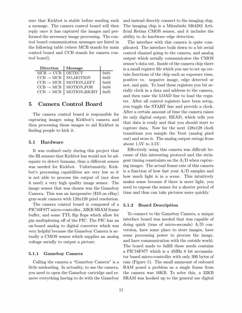
PIC16F877 micro-controller, 32KB SRAM framebu"er, and some TTL flip flops which allow forpin multiplexing o" of the PIC. The PIC has anon-board analog to digital converter which wasvery helpful because the Gameboy Camera is ac-tually a CMOS sensor which supplies an analogvoltage serially to output a picture.
5.1.1 Gameboy Camera
Calling the camera a “Gameboy Camera” is alittle misleading. In actuality, to use the camera,you need to open the Gameboy cartridge and re-move everything having to do with the Gameboy
and instead directly connect to the imaging chip.The imaging chip is a Mitsubishi M64282 Arti-ficial Retina CMOS sensor, and it includes theability to do hardware edge detection.The interface with this camera is quite com-plicated. The interface boils down to a bit serialcontrol channel going to the camera, and analogoutput which serially communicates the CMOSsensor’s data out. Inside of the camera chip thereis a small register file which you use to set up cer-tain functions of the chip such as exposure time,positive vs. negative image, edge detected ornot, and gain. To load these registers you bit se-rially clock in a data and address to the camera,and then raise the LOAD line to load the regis-ter. After all control registers have been setup,you toggle the START line and provide a clock.After a certain amount of time the camera raisesits only digital output, READ, which tells youthat data is ready and that you should start tocapture data. Now for the next 128x128 clocktransitions you sample the Vout (analog pixelout) and store it. The analog output swings fromabout 1.5V to 3.5V.E"ectively using this camera was di!cult be-cause of this interesting protocol and the strin-gent timing constraints on the A/D when captur-ing images. The actual frame rate of this camerais a function of how fast your A/D samples andhow much light is in a scene. This intuitivelymakes sense because if there is more light, youneed to expose the sensor for a shorter period oftime and thus can take pictures more quickly.
5.1.2 Board Description
To connect to the Gameboy Camera, a uniqueinterface board was needed that was capable ofdoing quick (tens of micro-seconds) A/D con-version, have some place to store images, havesome processing power to process the image,and have communication with the outside world.The board made to fulfill these needs containsa PIC16F877 which is a 4MHz 8 bit accumula-tor based micro-controller with only 300 bytes ofram (Figure 11. The small ammount of onboardRAM posed a problem as a single frame fromthe camera was 16KB. To solve this, a 32KBSRAM was hooked up to the general use digital
11
I/O pins on the PIC. External TTL flip flops en-abled the PIC to time multiplex the address anddata buses ont the same PIC digital I/O pins.To obtain pictures, the PIC’s on-chip A/D
was used. To get good contrast in the imagesa voltage reference needed to be provided to theA/D. A voltage divider was used to generate the1.5V Vref" and 3.5V Vref+ needed. The on-chipA/D is limited to 24 micro-seconds, thus if therewere no other overheads, one can only capture 3frames a second (24µs ! 128 ! 128 = .39s).The camera control board also needs to com-
municate gathered information with the outsideworld. To that end, the PIC’s on-chip UART wasused. We used a 9600 baud connection to com-municate pictures and information to the out-side world. The same RS232 interface is usedto communicate with an desktop computer fordebugging and with the main controller board.
5.2 Software
There were two main software interfacing is-sues. One being how to use serial communica-tions. Interfacing with RS232 was surprisinglyeasy. On the PIC all you really have to do is setup some special purpose registers which set thebaud rate. Then to send and receive you sim-ply write to a send register and read from a recvregister. You can also check a di"erent registerto see if incoming tra!c has come thus allowingyou to do a blocking receive. A problem whichcropped up in the course of development was get-ting the two controller boards which were startedup out of sync into sync via this asynchronouscommunications channel. It was made worse bythe channel being full duplex. Having a full du-plex channel is usually a good thing, but gettingto a point where two PICs can have a conver-sation requires a synchronizing handshake. Athree way handshake was used which allowed thetwo PICs to get synchronized after startup. Af-ter that the interfacing protocol works by havingthe motor control board ask if the camera boardsaw motion and then the camera control boardresponds saying if any was detected and where.The other interesting piece of interfacing soft-
ware is the software which communicates withthe camera. This software implements the pro-
tocol described in Section 5.1.1. This softwarerequired the use of the PIC’s interrupt facilitiesto generate a stable software clock for the cameradevice. This was an unfortunate artifact of thecamera chip using the same clock pin for logiccontrol and image capture. When the PIC isconfiguring the registers on the camera it slowlyclocks in data, and when an actual image is be-ing captured, an interrupt routine gets fired onceevery 48 micro-seconds to toggle the clock pin.If the the camera is outputting pixels, it analogto digital converts them and stores them to theo" chip SRAM.
5.2.1 Picture Capture
The only real feedback to know if you haveproperly configured the camera is to take a lookat pictures generated by the camera. To do this,PIC assembly was written to capture a frameand then dump the frame to the computer overthe RS232 port. On the computer side, a termi-nal program waits and receives the data into afile. This file is post-processed in Matlab, andthen displayed as an image. Figure 12 shows therobot looking at David’s legs in the lab. Fig-ure 13 shows Kickbot exploring Tech Square’s6th floor playroom. Lastly Figure 14 shows Kick-bot’s view of a hallway on the 6th floor.
5.2.2 Motion Detection
In order for Kickbot to find people to antag-onize, it needs some way to detect them, andan easy way to detect people is to look for mo-tion. To detect motion, Kickbot simply capturestwo consecutive frames and it unsigned subtractsone frame from the other. Any motion will showup as a di"erence in the two frames. This ofcourse assumes that the camera is not moving.The test version of the program takes two frames,subtracts one from the other, and then outputsthem to the serial port. An example of the re-sults can be seen in Figure 15. This is a phototaken with Chris on the left side of the framemoving himself and his hand. Figure 16 showsthe motion map (the di" done on the PIC) of thetwo captured frames. The white represents themovement and indeed it picks up Chris moving
12

Figure 12: Kickbot Looking at Dave’s Legs
Figure 13: View of 6th Floor Playroom
Figure 14: View Down 6th Floor Hall
Figure 15: Picture with Chris Moving
Figure 16: Chris Moving Motion Map
and his hand moving.
For Kickbot, a program analyzes the di"erencebetween two frames and reports back to the maincontroller board if there was motion and if so wasthe motion to the left, right, or straight ahead.This communication occurs over the RS232 portbetween the two boards. An optimization wasmade that does not require the PIC to write thepicture back to the SRAM, but does a runningsummation of how much movement is detectedinto the three buckets, left, right, and middle.Lastly these totals are compared to a hard-codedmovement threshold which is tuned for motiondetection.
13

6 Conclusion
Overall we feel that Kickbot was a great suc-cess. We fulfilled our objectives of making a realrobot that you can kick and used it to investigateinteresting real world embodied behaviors.From this project we are able to draw three
conclusions about building real robots. First,building a real robot is expensive. We receivedno support from our research groups and had tofinance the project ourselves. Second, buildinga real robot is hard. We had to learn how tomachine custom parts, and real world consider-ations such as power supply noise, faulty wiring,IR sensor noise, and the physics of a sphericalrobot can cause significant complications. Fi-nally, building a real robot is fun. We enjoyedthis project and would build another robot in thefuture.
14
![Abstract arXiv:1704.07333v1 [cs.CV] 24 Apr 2017 · 2019-07-30 · 1 arXiv:1704.07333v1 [cs.CV] 24 Apr 2017. su rf su rfb oar d ta lk _ o n _ pho n e ce ll pho n e k ick sp o rts b](https://img.pdfslide.us/doc/110x75/5f68fac2a038a2008310a2ca/abstract-arxiv170407333v1-cscv-24-apr-2017-2019-07-30-1-arxiv170407333v1.jpg)