Embed Size (px)
Citation preview
PG-1
POWER SUPPLY, GROUND & CIRCUIT ELEMENTS
K ELECTRICAL
CONTENTS
C
D
E
F
G
H
I
J
L
M
SECTION PGA
B
PG
Revision: February 2007 2006 Pathfinder
PRECAUTIONS .......................................................... 3Precautions for Supplemental Restraint System (SRS) “AIR BAG” and “SEAT BELT PRE-TEN-SIONER” .................................................................. 3
POWER SUPPLY ROUTING CIRCUIT ...................... 4Schematic ................................................................ 4Wiring Diagram — POWER — ................................. 6
BATTERY POWER SUPPLY — IGNITION SW. IN ANY POSITION ................................................ 6ACCESSORY POWER SUPPLY — IGNITION SW. IN ACC OR ON ............................................ 12IGNITION POWER SUPPLY — IGNITION SW. IN ON .................................................................. 13IGNITION POWER SUPPLY — IGNITION SW. IN ON AND/OR START ....................................... 14
Fuse ....................................................................... 17Fusible Link ............................................................ 17Circuit Breaker (Built Into BCM) ............................. 17
IPDM E/R (INTELLIGENT POWER DISTRIBUTION MODULE ENGINE ROOM) ...................................... 18
System Description ................................................ 18SYSTEMS CONTROLLED BY IPDM E/R ........... 18CAN COMMUNICATION LINE CONTROL ......... 18IPDM E/R STATUS CONTROL ........................... 19
CAN Communication System Description .............. 19Function of Detecting Ignition Relay Malfunction ... 19CONSULT-II Function (IPDM E/R) ......................... 20
CONSULT-II BASIC OPERATION ...................... 20SELF-DIAGNOSTIC RESULTS .......................... 21DATA MONITOR ................................................. 22ACTIVE TEST ..................................................... 23
Auto Active Test ..................................................... 24DESCRIPTION .................................................... 24OPERATION PROCEDURE ............................... 24INSPECTION IN AUTO ACTIVE TEST MODE ... 24
Schematic .............................................................. 27IPDM E/R Terminal Arrangement ........................... 28Terminals and Reference Values for IPDM E/R ..... 29IPDM E/R Power/Ground Circuit Inspection .......... 31
Inspection with CONSULT-II (Self-Diagnosis) ........ 32Removal and Installation of IPDM E/R ................... 34
REMOVAL ........................................................... 34INSTALLATION ................................................... 34
GROUND CIRCUIT ................................................... 35Ground Distribution ................................................. 35
MAIN HARNESS ................................................. 35ENGINE ROOM HARNESS ................................ 38ENGINE CONTROL HARNESS .......................... 41BODY HARNESS ................................................ 42BODY NO. 2 HARNESS ..................................... 43BACK DOOR NO. 2 AND BACK DOOR HAR-NESS ................................................................... 44
HARNESS ................................................................. 45Harness Layout ...................................................... 45
HOW TO READ HARNESS LAYOUT ................. 45OUTLINE ............................................................. 46MAIN HARNESS ................................................. 47ENGINE ROOM HARNESS (RH VIEW) ............. 50ENGINE ROOM HARNESS (LH VIEW) .............. 54ENGINE CONTROL HARNESS .......................... 56CHASSIS HARNESS .......................................... 58BODY HARNESS ................................................ 60BODY NO. 2 HARNESS ..................................... 62ROOM LAMP HARNESS .................................... 64FRONT DOOR LH HARNESS ............................ 66FRONT DOOR RH HARNESS ............................ 66REAR DOOR LH HARNESS ............................... 67REAR DOOR RH HARNESS .............................. 67BACK DOOR HARNESS .................................... 68
Wiring Diagram Codes (Cell Codes) ...................... 70ELECTRICAL UNITS LOCATION ............................ 73
Electrical Units Location ......................................... 73ENGINE COMPARTMENT .................................. 73PASSENGER COMPARTMENT ......................... 74
HARNESS CONNECTOR ......................................... 76Description .............................................................. 76
HARNESS CONNECTOR (TAB-LOCKING TYPE) .................................................................. 76HARNESS CONNECTOR (SLIDE-LOCKING
PG-2Revision: February 2007 2006 Pathfinder
TYPE) .................................................................. 77HARNESS CONNECTOR (LEVER LOCKING TYPE) .................................................................. 78HARNESS CONNECTOR (DIRECT-CONNECT SRS COMPONENT TYPE) ................................. 79
ELECTRICAL UNITS ................................................ 80Terminal Arrangement ............................................ 80
STANDARDIZED RELAY .......................................... 81Description .............................................................. 81
NORMAL OPEN, NORMAL CLOSED AND
MIXED TYPE RELAYS ........................................81TYPE OF STANDARDIZED RELAYS ..................81
SUPER MULTIPLE JUNCTION (SMJ) ......................83Terminal Arrangement .............................................83
FUSE BLOCK-JUNCTION BOX (J/B) ......................85Terminal Arrangement .............................................85
FUSE AND FUSIBLE LINK BOX ..............................86Terminal Arrangement .............................................86
FUSE AND RELAY BOX ...........................................87Terminal Arrangement .............................................87
PRECAUTIONS
PG-3
C
D
E
F
G
H
I
J
L
M
A
B
PG
Revision: February 2007 2006 Pathfinder
PRECAUTIONS PFP:00011
Precautions for Supplemental Restraint System (SRS) “AIR BAG” and “SEAT BELT PRE-TENSIONER” EKS00G8A
The Supplemental Restraint System such as “AIR BAG” and “SEAT BELT PRE-TENSIONER”, used alongwith a front seat belt, helps to reduce the risk or severity of injury to the driver and front passenger for certaintypes of collision. This system includes seat belt switch inputs and dual stage front air bag modules. The SRSsystem uses the seat belt switches to determine the front air bag deployment, and may only deploy one frontair bag, depending on the severity of a collision and whether the front occupants are belted or unbelted.Information necessary to service the system safely is included in the SRS and SB section of this Service Man-ual.WARNING:� To avoid rendering the SRS inoperative, which could increase the risk of personal injury or death
in the event of a collision which would result in air bag inflation, all maintenance must be per-formed by an authorized NISSAN/INFINITI dealer.
� Improper maintenance, including incorrect removal and installation of the SRS, can lead to per-sonal injury caused by unintentional activation of the system. For removal of Spiral Cable and AirBag Module, see the SRS section.
� Do not use electrical test equipment on any circuit related to the SRS unless instructed to in thisService Manual. SRS wiring harnesses can be identified by yellow and/or orange harnesses orharness connectors.
PG-4
POWER SUPPLY ROUTING CIRCUIT
Revision: February 2007 2006 Pathfinder
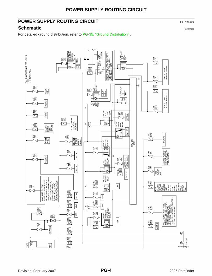
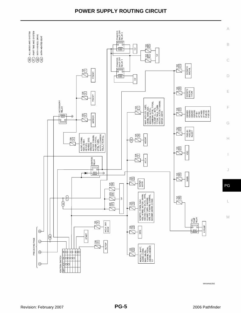
POWER SUPPLY ROUTING CIRCUIT PFP:24110
Schematic EKS00G8C
For detailed ground distribution, refer to PG-35, "Ground Distribution" .
WKWA6024E
POWER SUPPLY ROUTING CIRCUIT
PG-5
C
D
E
F
G
H
I
J
L
M
A
B
PG
Revision: February 2007 2006 Pathfinder
WKWA6025E
PG-6
POWER SUPPLY ROUTING CIRCUIT
Revision: February 2007 2006 Pathfinder
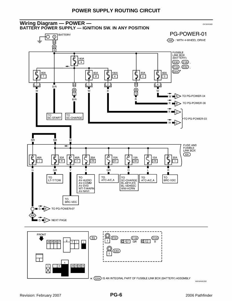
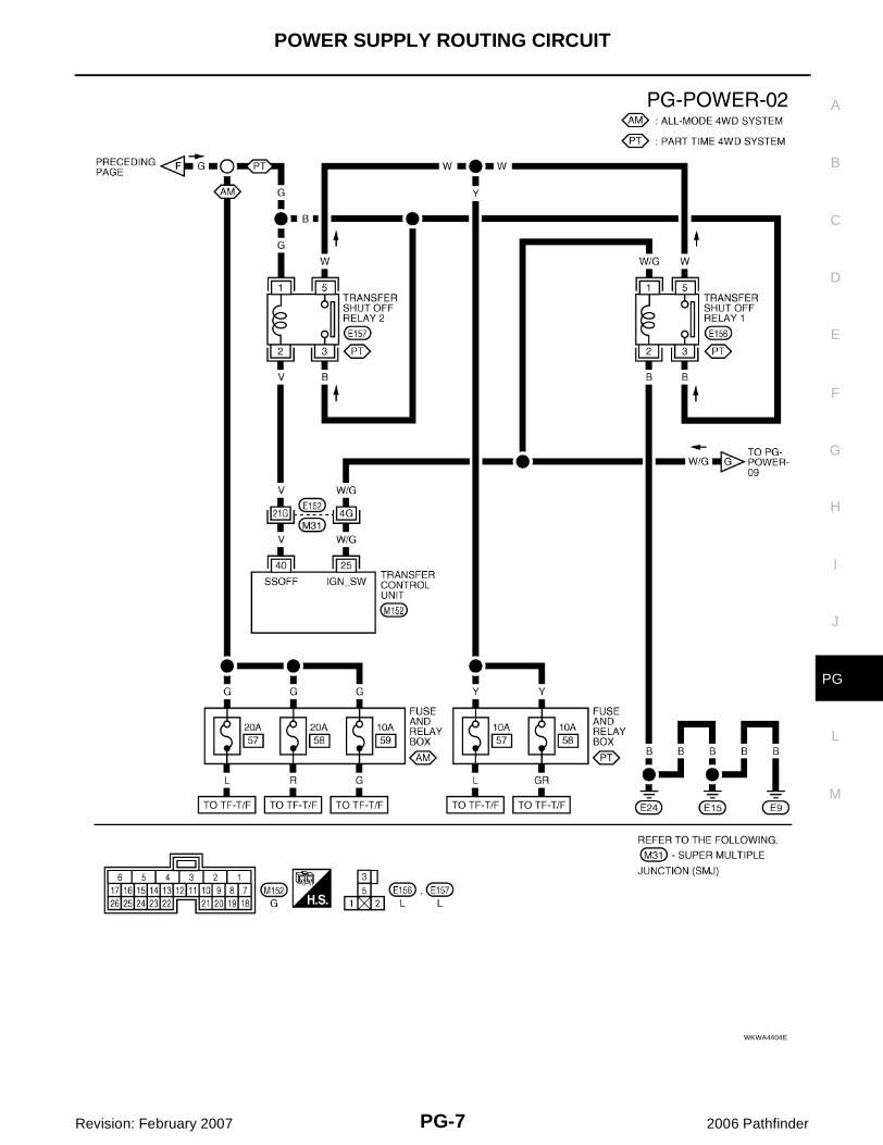
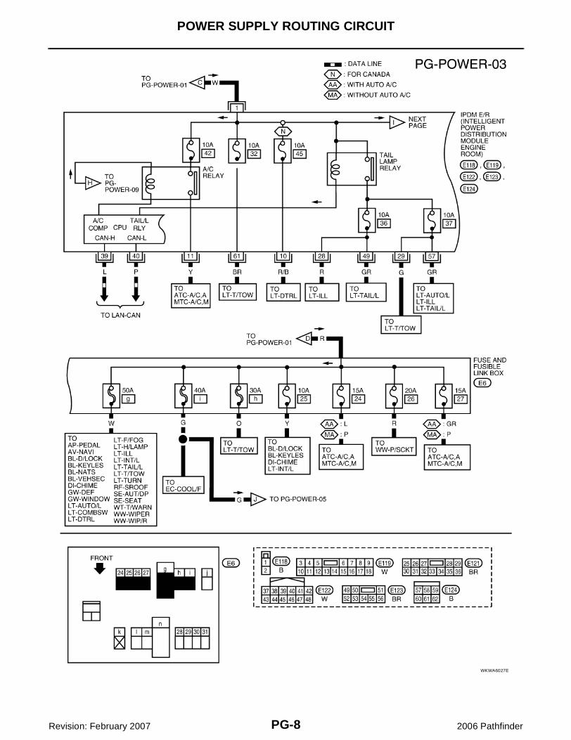
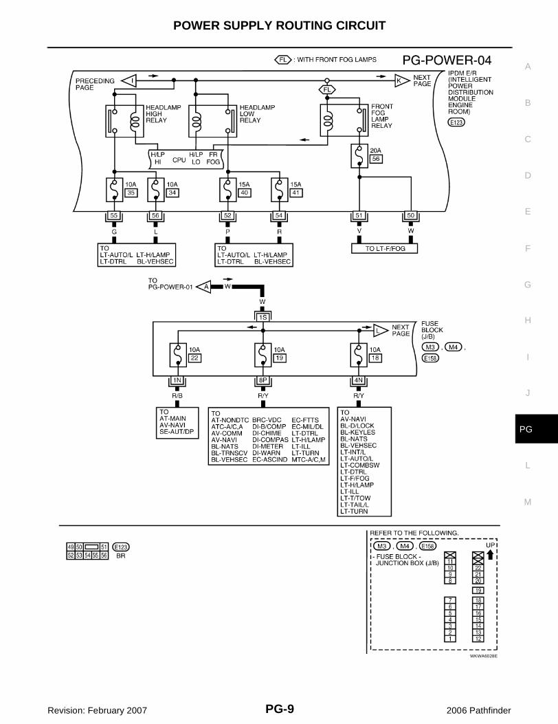
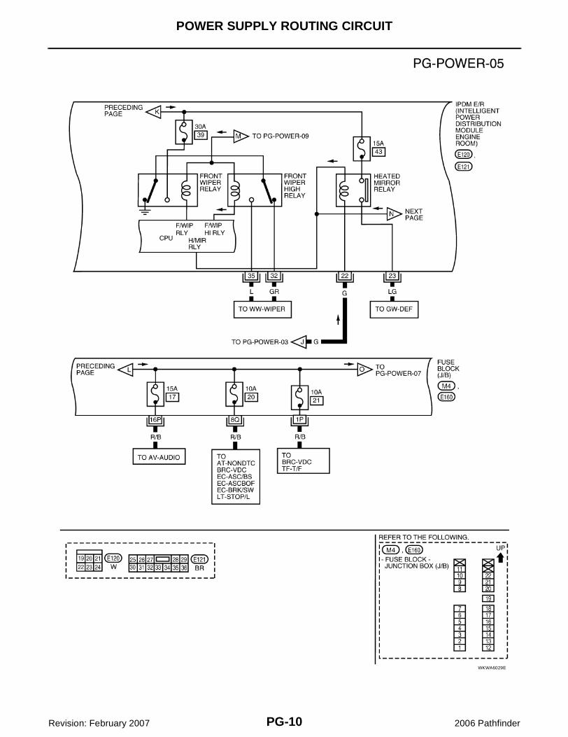
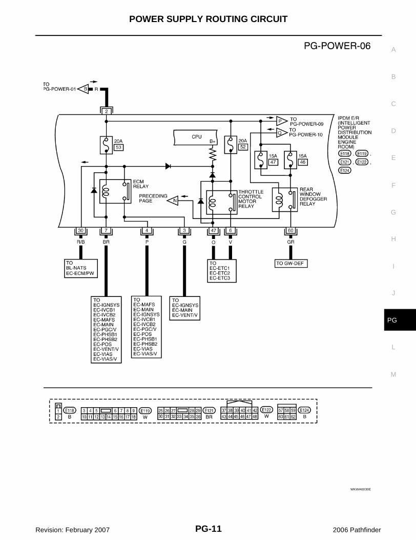
Wiring Diagram — POWER — EKS00G8D
BATTERY POWER SUPPLY — IGNITION SW. IN ANY POSITION
WKWA6026E
POWER SUPPLY ROUTING CIRCUIT
PG-7
C
D
E
F
G
H
I
J
L
M
A
B
PG
Revision: February 2007 2006 Pathfinder
WKWA4404E
PG-8
POWER SUPPLY ROUTING CIRCUIT
Revision: February 2007 2006 Pathfinder
WKWA6027E
POWER SUPPLY ROUTING CIRCUIT
PG-9
C
D
E
F
G
H
I
J
L
M
A
B
PG
Revision: February 2007 2006 Pathfinder
WKWA6028E
PG-10
POWER SUPPLY ROUTING CIRCUIT
Revision: February 2007 2006 Pathfinder
WKWA6029E
POWER SUPPLY ROUTING CIRCUIT
PG-11
C
D
E
F
G
H
I
J
L
M
A
B
PG
Revision: February 2007 2006 Pathfinder
WKWA6030E
PG-12
POWER SUPPLY ROUTING CIRCUIT
Revision: February 2007 2006 Pathfinder
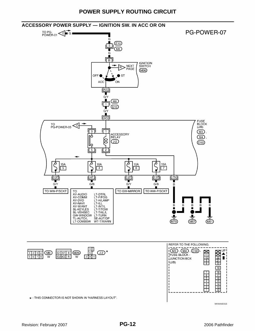
ACCESSORY POWER SUPPLY — IGNITION SW. IN ACC OR ON
WKWA6031E
POWER SUPPLY ROUTING CIRCUIT
PG-13
C
D
E
F
G
H
I
J
L
M
A
B
PG
Revision: February 2007 2006 Pathfinder
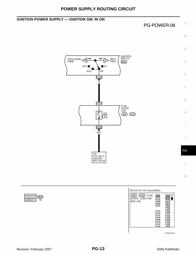
IGNITION POWER SUPPLY — IGNITION SW. IN ON
WKWA4410E
PG-14
POWER SUPPLY ROUTING CIRCUIT
Revision: February 2007 2006 Pathfinder
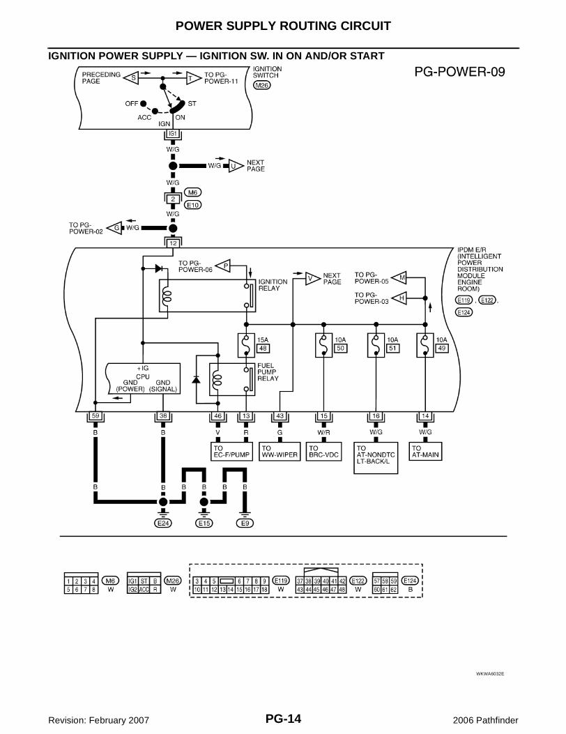
IGNITION POWER SUPPLY — IGNITION SW. IN ON AND/OR START
WKWA6032E
POWER SUPPLY ROUTING CIRCUIT
PG-15
C
D
E
F
G
H
I
J
L
M
A
B
PG
Revision: February 2007 2006 Pathfinder
WKWA6033E
PG-16
POWER SUPPLY ROUTING CIRCUIT
Revision: February 2007 2006 Pathfinder
WKWA6034E
POWER SUPPLY ROUTING CIRCUIT
PG-17
C
D
E
F
G
H
I
J
L
M
A
B
PG
Revision: February 2007 2006 Pathfinder
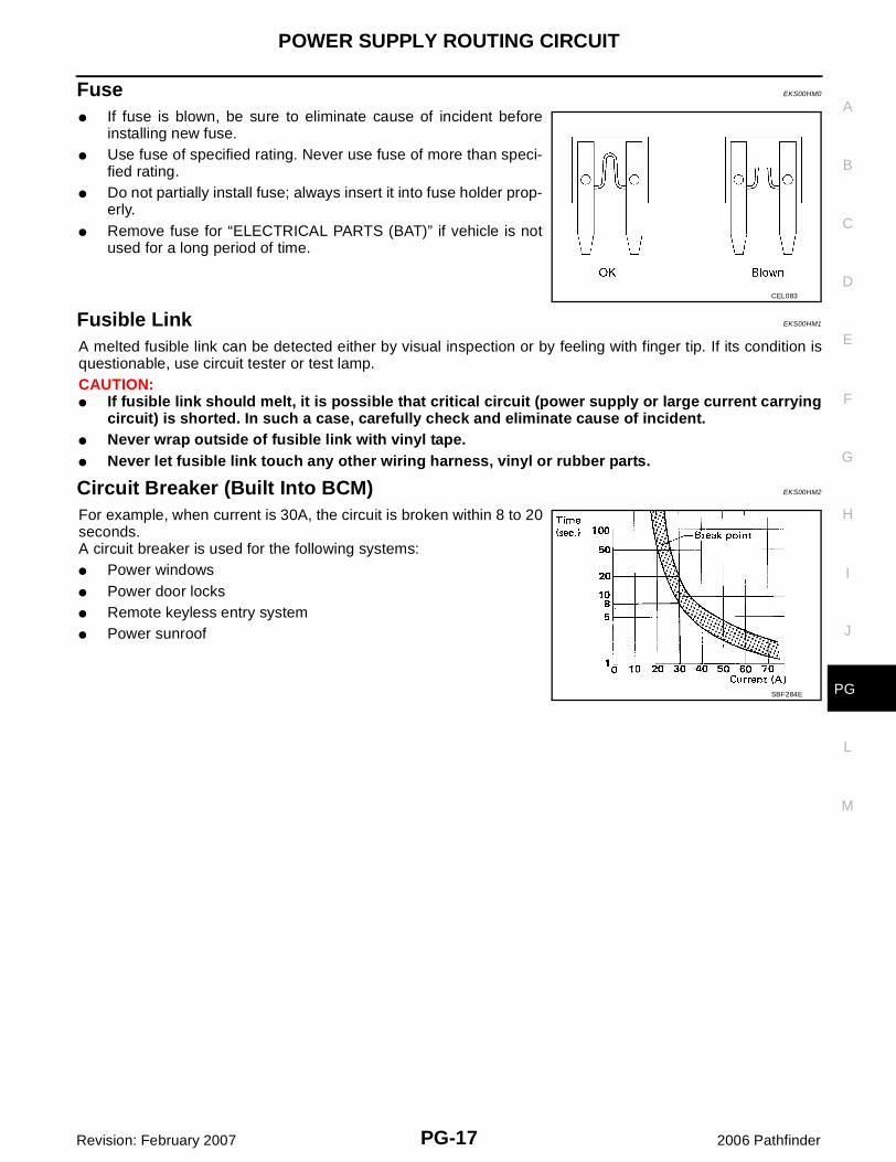
Fuse EKS00HM0
� If fuse is blown, be sure to eliminate cause of incident beforeinstalling new fuse.
� Use fuse of specified rating. Never use fuse of more than speci-fied rating.
� Do not partially install fuse; always insert it into fuse holder prop-erly.
� Remove fuse for “ELECTRICAL PARTS (BAT)” if vehicle is notused for a long period of time.
Fusible Link EKS00HM1
A melted fusible link can be detected either by visual inspection or by feeling with finger tip. If its condition isquestionable, use circuit tester or test lamp.CAUTION:� If fusible link should melt, it is possible that critical circuit (power supply or large current carrying
circuit) is shorted. In such a case, carefully check and eliminate cause of incident.� Never wrap outside of fusible link with vinyl tape. � Never let fusible link touch any other wiring harness, vinyl or rubber parts.
Circuit Breaker (Built Into BCM) EKS00HM2
For example, when current is 30A, the circuit is broken within 8 to 20seconds.A circuit breaker is used for the following systems:� Power windows� Power door locks� Remote keyless entry system� Power sunroof
CEL083
SBF284E
PG-18
IPDM E/R (INTELLIGENT POWER DISTRIBUTION MODULE ENGINE ROOM)
Revision: February 2007 2006 Pathfinder
IPDM E/R (INTELLIGENT POWER DISTRIBUTION MODULE ENGINE ROOM)PFP:284B7
System Description EKS00G8E
� IPDM E/R (Intelligent Power Distribution Module Engine Room) integrates the relay box and fuse blockwhich were originally placed in engine compartment. It controls integrated relays via IPDM E/R control cir-cuits.
� IPDM E/R-integrated control circuits perform ON-OFF operation of relays, CAN communication control,etc.
� It controls operation of each electrical component via ECM, BCM and CAN communication lines.CAUTION:None of the IPDM E/R integrated relays can be removed.
SYSTEMS CONTROLLED BY IPDM E/R1. Lamp control
Using CAN communication lines, it receives signals from the BCM and controls the following lamps:� Headlamps (High, Low)� Daytime light relay control (canada only)� Parking lamps and side marker lamps� Tail and license plate lamps� Front fog lamps
2. Wiper controlUsing CAN communication lines, it receives signals from the BCM and controls the front wipers.
3. Daytime light relay controlUsing CAN communication lines, it receives signals from the BCM and controls the daytime light relay.
4. Generator controlUsing CAN communication lines, it receives signals from the ECM and controls power generation output.
5. Rear window defogger relay controlUsing CAN communication lines, it receives signals from the BCM and controls the rear window defoggerrelay.
6. A/C compressor controlUsing CAN communication lines, it receives signals from the BCM and controls the A/C compressor(magnetic clutch).
7. Starter controlUsing CAN communication lines, it receives signals from the BCM and controls the starter relay.
8. Cooling fan controlUsing CAN communication lines, it receives signals from the ECM and controls the cooling fan relays.
9. Horn controlUsing CAN communication lines, it receives signals from the BCM and controls the horn relay.
CAN COMMUNICATION LINE CONTROLWith CAN communication, by connecting each control unit using two communication lines (CAN L-line, CANH-line), it is possible to transmit a maximum amount of information with minimum wiring. Each control unit cantransmit and receive data, and reads necessary information only.1. Fail-safe control
� When CAN communication with other control units is impossible, IPDM E/R performs fail-safe control.After CAN communication returns to normal operation, it also returns to normal control.
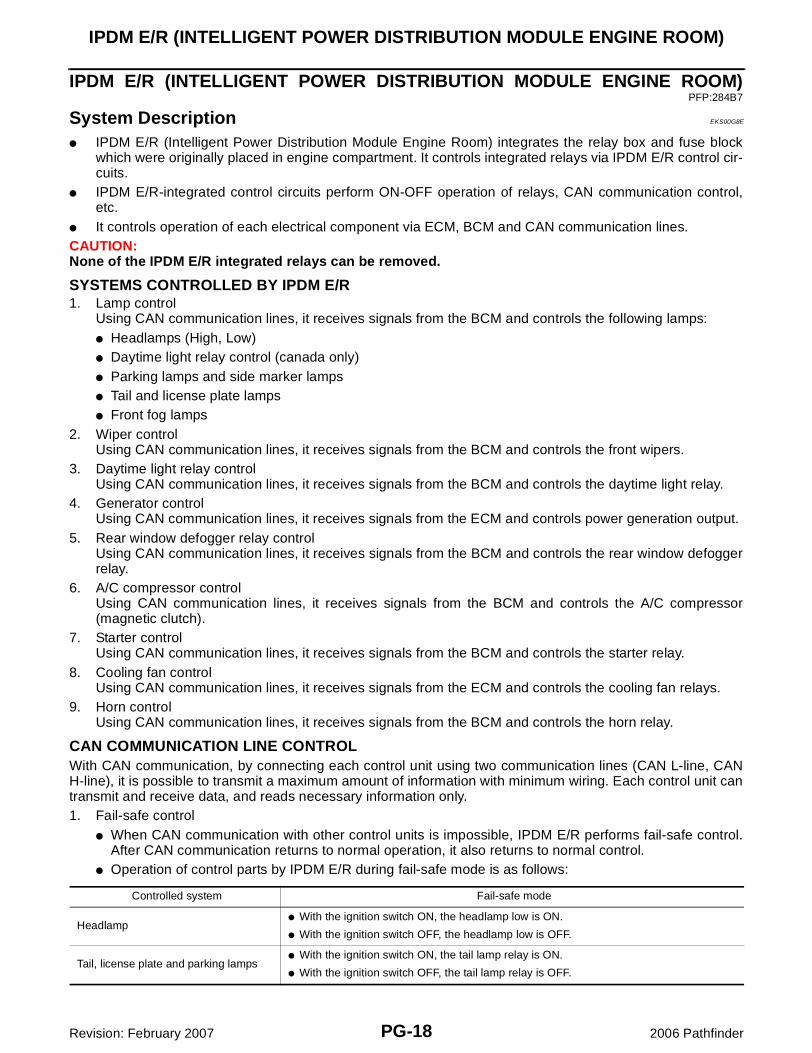
� Operation of control parts by IPDM E/R during fail-safe mode is as follows:
Controlled system Fail-safe mode
Headlamp� With the ignition switch ON, the headlamp low is ON.
� With the ignition switch OFF, the headlamp low is OFF.
Tail, license plate and parking lamps� With the ignition switch ON, the tail lamp relay is ON.
� With the ignition switch OFF, the tail lamp relay is OFF.
IPDM E/R (INTELLIGENT POWER DISTRIBUTION MODULE ENGINE ROOM)
PG-19
C
D
E
F
G
H
I
J
L
M
A
B
PG
Revision: February 2007 2006 Pathfinder
IPDM E/R STATUS CONTROLIn order to save power, IPDM E/R switches status by itself based on each operating condition.1. CAN communication status
� CAN communication is normally performed with other control units.� Individual unit control by IPDM E/R is normally performed.� When sleep request signal is received from BCM, mode is switched to sleep waiting status.
2. Sleep waiting status� Process to stop CAN communication is activated.� All systems controlled by IPDM E/R are stopped. When 3 seconds have elapsed after CAN communi-
cation with other control units is stopped, mode switches to sleep status.3. Sleep status
� IPDM E/R operates in low current-consumption mode.� CAN communication is stopped.� When a change in CAN communication signal is detected, mode switches to CAN communication sta-
tus.� When a change in ignition switch signal is detected, mode switches to CAN communication status.
CAN Communication System Description EKS00G8F
Refer to LAN-25, "CAN COMMUNICATION" .
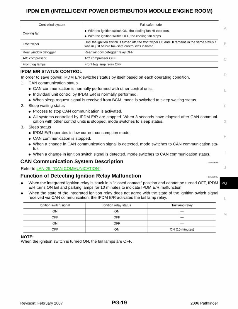
Function of Detecting Ignition Relay Malfunction EKS00G8G
� When the integrated ignition relay is stuck in a "closed contact" position and cannot be turned OFF, IPDME/R turns ON tail and parking lamps for 10 minutes to indicate IPDM E/R malfunction.
� When the state of the integrated ignition relay does not agree with the state of the ignition switch signalreceived via CAN communication, the IPDM E/R activates the tail lamp relay.
NOTE:When the ignition switch is turned ON, the tail lamps are OFF.
Cooling fan� With the ignition switch ON, the cooling fan HI operates.
� With the ignition switch OFF, the cooling fan stops.
Front wiperUntil the ignition switch is turned off, the front wiper LO and HI remains in the same status it was in just before fail−safe control was initiated.
Rear window defogger Rear window defogger relay OFF
A/C compressor A/C compressor OFF
Front fog lamps Front fog lamp relay OFF
Controlled system Fail-safe mode
Ignition switch signal Ignition relay status Tail lamp relay
ON ON —
OFF OFF —
ON OFF —
OFF ON ON (10 minutes)
PG-20
IPDM E/R (INTELLIGENT POWER DISTRIBUTION MODULE ENGINE ROOM)
Revision: February 2007 2006 Pathfinder
CONSULT-II Function (IPDM E/R) EKS00G8H
CONSULT-II can display each diagnostic item using the diagnostic test modes shown following.
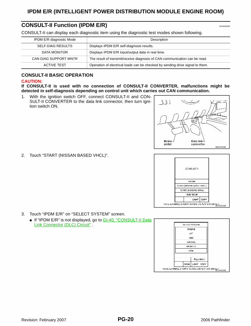
CONSULT-II BASIC OPERATIONCAUTION:If CONSULT-II is used with no connection of CONSULT-II CONVERTER, malfunctions might bedetected in self-diagnosis depending on control unit which carries out CAN communication.1. With the ignition switch OFF, connect CONSULT-II and CON-
SULT-II CONVERTER to the data link connector, then turn igni-tion switch ON.
2. Touch “START (NISSAN BASED VHCL)”.
3. Touch “IPDM E/R” on “SELECT SYSTEM” screen.� If “IPDM E/R” is not displayed, go to GI-40, "CONSULT-II Data
Link Connector (DLC) Circuit" .
IPDM E/R diagnostic Mode Description
SELF-DIAG RESULTS Displays IPDM E/R self-diagnosis results.
DATA MONITOR Displays IPDM E/R input/output data in real time.
CAN DIAG SUPPORT MNTR The result of transmit/receive diagnosis of CAN communication can be read.
ACTIVE TEST Operation of electrical loads can be checked by sending drive signal to them.
BBIA0538E
BCIA0029E
BCIA0030E
IPDM E/R (INTELLIGENT POWER DISTRIBUTION MODULE ENGINE ROOM)
PG-21
C
D
E
F
G
H
I
J
L
M
A
B
PG
Revision: February 2007 2006 Pathfinder
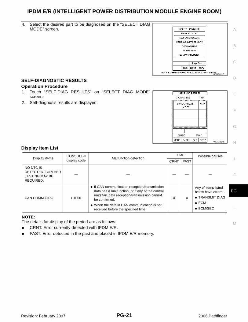
4. Select the desired part to be diagnosed on the “SELECT DIAGMODE” screen.
SELF-DIAGNOSTIC RESULTSOperation Procedure1. Touch “SELF-DIAG RESULTS” on “SELECT DIAG MODE”
screen.2. Self-diagnosis results are displayed.
Display Item List
NOTE:The details for display of the period are as follows:� CRNT: Error currently detected with IPDM E/R.� PAST: Error detected in the past and placed in IPDM E/R memory.
BCIA0031E
WKIA1264E
Display itemsCONSULT-II display code
Malfunction detectionTIME Possible causes
CRNT PAST
NO DTC IS DETECTED. FURTHER TESTING MAY BE REQUIRED.
— — — — —
CAN COMM CIRC U1000
� If CAN communication reception/transmission data has a malfunction, or if any of the control units fail, data reception/transmission cannot be confirmed.
� When the data in CAN communication is not received before the specified time.
X X
Any of items listed below have errors:
� TRANSMIT DIAG
� ECM
� BCM/SEC
PG-22
IPDM E/R (INTELLIGENT POWER DISTRIBUTION MODULE ENGINE ROOM)
Revision: February 2007 2006 Pathfinder
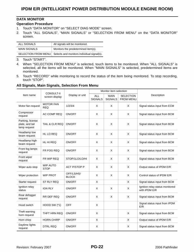
DATA MONITOROperation Procedure1. Touch “DATA MONITOR” on “SELECT DIAG MODE” screen.2. Touch "ALL SIGNALS”, “MAIN SIGNALS” or “SELECTION FROM MENU” on the “DATA MONITOR”
screen.
3. Touch “START”.4. When "SELECTION FROM MENU" is selected, touch items to be monitored. When "ALL SIGNALS" is
selected, all the items will be monitored. When "MAIN SIGNALS" is selected, predetermined items aremonitored.
5. Touch “RECORD” while monitoring to record the status of the item being monitored. To stop recording,touch “STOP”.
All Signals, Main Signals, Selection From Menu
ALL SIGNALS All signals will be monitored.
MAIN SIGNALS Monitors the predetermined item(s).
SELECTION FROM MENU Selects and monitors individual signal(s).
Item nameCONSULT-II
screen displayDisplay or unit
Monitor item selection
DescriptionALLSIGNALS
MAIN SIGNALS
SELECTION FROM MENU
Motor fan requestMOTOR FAN REQ
1/2/3/4 X X X Signal status input from ECM
Compressor request
AC COMP REQ ON/OFF X X X Signal status input from BCM
Parking, license plate, and tail lamp request
TAIL & CLR REQ ON/OFF X X X Signal status input from BCM
Headlamp low beam request
HL LO REQ ON/OFF X X X Signal status input from BCM
Headlamp high beam request
HL HI REQ ON/OFF X X X Signal status input from BCM
Front fog lamps request
FR FOG REQ ON/OFF X X X Signal status input from BCM
Front wiper request
FR WIP REQ STOP/1LO/LO/HI X X X Signal status input from BCM
Wiper auto stopWIP AUTO STOP
ACT P/STOP P X X X Output status of IPDM E/R
Wiper protection WIP PROTOFF/LS/HS/BLOCK
X X X Control status of IPDM E/R
Starter request ST RLY REQ ON/OFF X X Signal status input from BCM
Ignition relaystatus
IGN RLY ON/OFF X X XIgnition relay status monitored with IPDM E/R
Rear defogger request
RR DEF REQ ON/OFF X X X Signal status input from BCM
Hood switch HOOD SW (*1) OFF XSignal status input from IPDM E/R
Theft warning horn request
THFT HRN REQ ON/OFF X X Signal status input from BCM
Horn chirp HORN CHIRP ON/OFF X X Output status of IPDM E/R
Daytime lights request
DTRL REQ ON/OFF X X Signal status input from BCM
IPDM E/R (INTELLIGENT POWER DISTRIBUTION MODULE ENGINE ROOM)
PG-23
C
D
E
F
G
H
I
J
L
M
A
B
PG
Revision: February 2007 2006 Pathfinder
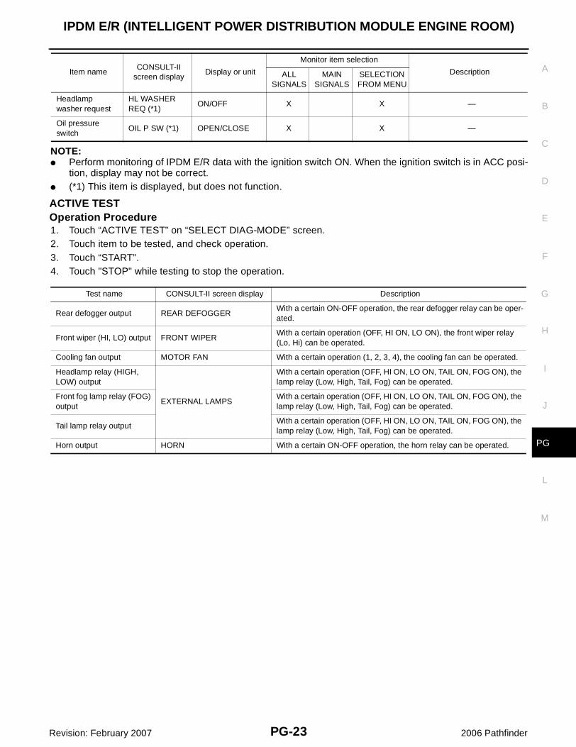
NOTE:� Perform monitoring of IPDM E/R data with the ignition switch ON. When the ignition switch is in ACC posi-
tion, display may not be correct.� (*1) This item is displayed, but does not function.
ACTIVE TESTOperation Procedure1. Touch “ACTIVE TEST” on “SELECT DIAG-MODE” screen.2. Touch item to be tested, and check operation.3. Touch “START”.4. Touch "STOP" while testing to stop the operation.
Headlamp washer request
HL WASHER REQ (*1)
ON/OFF X X —
Oil pressure switch
OIL P SW (*1) OPEN/CLOSE X X —
Item nameCONSULT-II
screen displayDisplay or unit
Monitor item selection
DescriptionALLSIGNALS
MAIN SIGNALS
SELECTION FROM MENU
Test name CONSULT-II screen display Description
Rear defogger output REAR DEFOGGERWith a certain ON-OFF operation, the rear defogger relay can be oper-ated.
Front wiper (HI, LO) output FRONT WIPERWith a certain operation (OFF, HI ON, LO ON), the front wiper relay (Lo, Hi) can be operated.
Cooling fan output MOTOR FAN With a certain operation (1, 2, 3, 4), the cooling fan can be operated.
Headlamp relay (HIGH, LOW) output
EXTERNAL LAMPS
With a certain operation (OFF, HI ON, LO ON, TAIL ON, FOG ON), the lamp relay (Low, High, Tail, Fog) can be operated.
Front fog lamp relay (FOG) output
With a certain operation (OFF, HI ON, LO ON, TAIL ON, FOG ON), the lamp relay (Low, High, Tail, Fog) can be operated.
Tail lamp relay outputWith a certain operation (OFF, HI ON, LO ON, TAIL ON, FOG ON), the lamp relay (Low, High, Tail, Fog) can be operated.
Horn output HORN With a certain ON-OFF operation, the horn relay can be operated.
PG-24
IPDM E/R (INTELLIGENT POWER DISTRIBUTION MODULE ENGINE ROOM)
Revision: February 2007 2006 Pathfinder
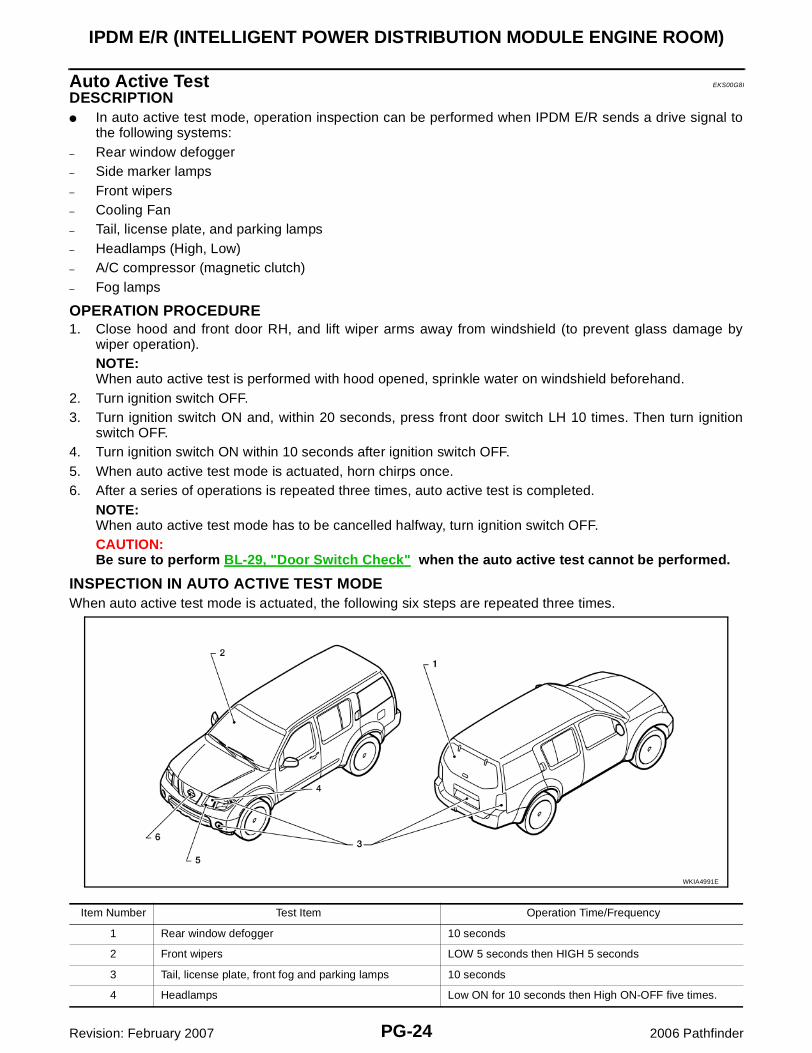
Auto Active Test EKS00G8I
DESCRIPTION� In auto active test mode, operation inspection can be performed when IPDM E/R sends a drive signal to
the following systems:– Rear window defogger– Side marker lamps– Front wipers– Cooling Fan– Tail, license plate, and parking lamps– Headlamps (High, Low)– A/C compressor (magnetic clutch)– Fog lamps
OPERATION PROCEDURE1. Close hood and front door RH, and lift wiper arms away from windshield (to prevent glass damage by
wiper operation).NOTE:When auto active test is performed with hood opened, sprinkle water on windshield beforehand.
2. Turn ignition switch OFF.3. Turn ignition switch ON and, within 20 seconds, press front door switch LH 10 times. Then turn ignition
switch OFF.4. Turn ignition switch ON within 10 seconds after ignition switch OFF. 5. When auto active test mode is actuated, horn chirps once.6. After a series of operations is repeated three times, auto active test is completed.
NOTE:When auto active test mode has to be cancelled halfway, turn ignition switch OFF.CAUTION:Be sure to perform BL-29, "Door Switch Check" when the auto active test cannot be performed.
INSPECTION IN AUTO ACTIVE TEST MODEWhen auto active test mode is actuated, the following six steps are repeated three times.
WKIA4991E
Item Number Test Item Operation Time/Frequency
1 Rear window defogger 10 seconds
2 Front wipers LOW 5 seconds then HIGH 5 seconds
3 Tail, license plate, front fog and parking lamps 10 seconds
4 Headlamps Low ON for 10 seconds then High ON-OFF five times.
IPDM E/R (INTELLIGENT POWER DISTRIBUTION MODULE ENGINE ROOM)
PG-25
C
D
E
F
G
H
I
J
L
M
A
B
PG
Revision: February 2007 2006 Pathfinder
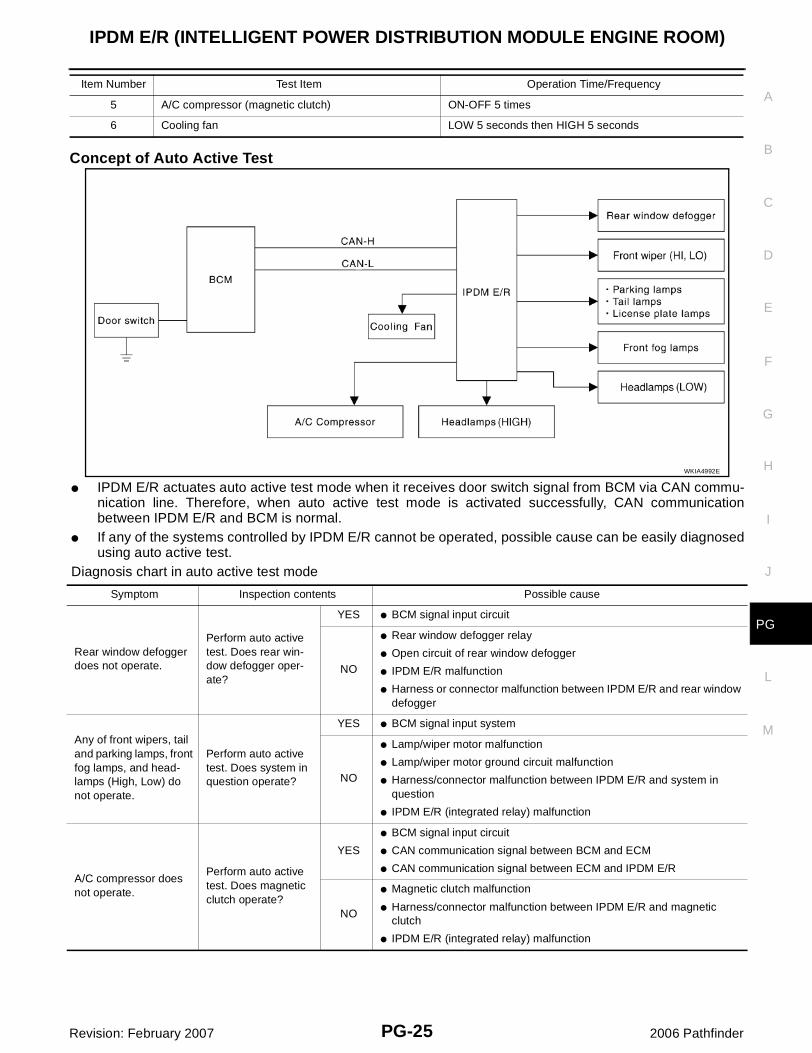
Concept of Auto Active Test
� IPDM E/R actuates auto active test mode when it receives door switch signal from BCM via CAN commu-nication line. Therefore, when auto active test mode is activated successfully, CAN communicationbetween IPDM E/R and BCM is normal.
� If any of the systems controlled by IPDM E/R cannot be operated, possible cause can be easily diagnosedusing auto active test.
Diagnosis chart in auto active test mode
5 A/C compressor (magnetic clutch) ON-OFF 5 times
6 Cooling fan LOW 5 seconds then HIGH 5 seconds
Item Number Test Item Operation Time/Frequency
WKIA4992E
Symptom Inspection contents Possible cause
Rear window defogger does not operate.
Perform auto active test. Does rear win-dow defogger oper-ate?
YES � BCM signal input circuit
NO
� Rear window defogger relay
� Open circuit of rear window defogger
� IPDM E/R malfunction
� Harness or connector malfunction between IPDM E/R and rear window defogger
Any of front wipers, tail and parking lamps, front fog lamps, and head-lamps (High, Low) do not operate.
Perform auto active test. Does system in question operate?
YES � BCM signal input system
NO
� Lamp/wiper motor malfunction
� Lamp/wiper motor ground circuit malfunction
� Harness/connector malfunction between IPDM E/R and system in question
� IPDM E/R (integrated relay) malfunction
A/C compressor does not operate.
Perform auto active test. Does magnetic clutch operate?
YES
� BCM signal input circuit
� CAN communication signal between BCM and ECM
� CAN communication signal between ECM and IPDM E/R
NO
� Magnetic clutch malfunction
� Harness/connector malfunction between IPDM E/R and magnetic clutch
� IPDM E/R (integrated relay) malfunction
PG-26
IPDM E/R (INTELLIGENT POWER DISTRIBUTION MODULE ENGINE ROOM)
Revision: February 2007 2006 Pathfinder
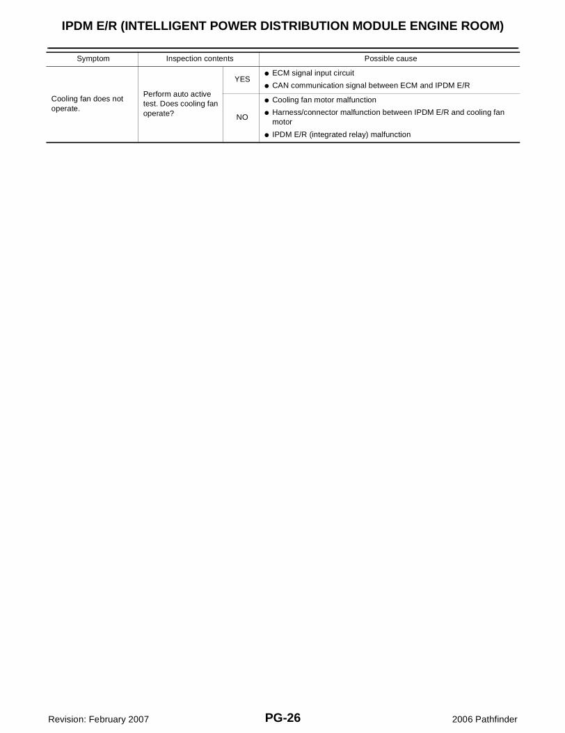
Cooling fan does not operate.
Perform auto active test. Does cooling fan operate?
YES� ECM signal input circuit
� CAN communication signal between ECM and IPDM E/R
NO
� Cooling fan motor malfunction
� Harness/connector malfunction between IPDM E/R and cooling fan motor
� IPDM E/R (integrated relay) malfunction
Symptom Inspection contents Possible cause
IPDM E/R (INTELLIGENT POWER DISTRIBUTION MODULE ENGINE ROOM)
PG-27
C
D
E
F
G
H
I
J
L
M
A
B
PG
Revision: February 2007 2006 Pathfinder
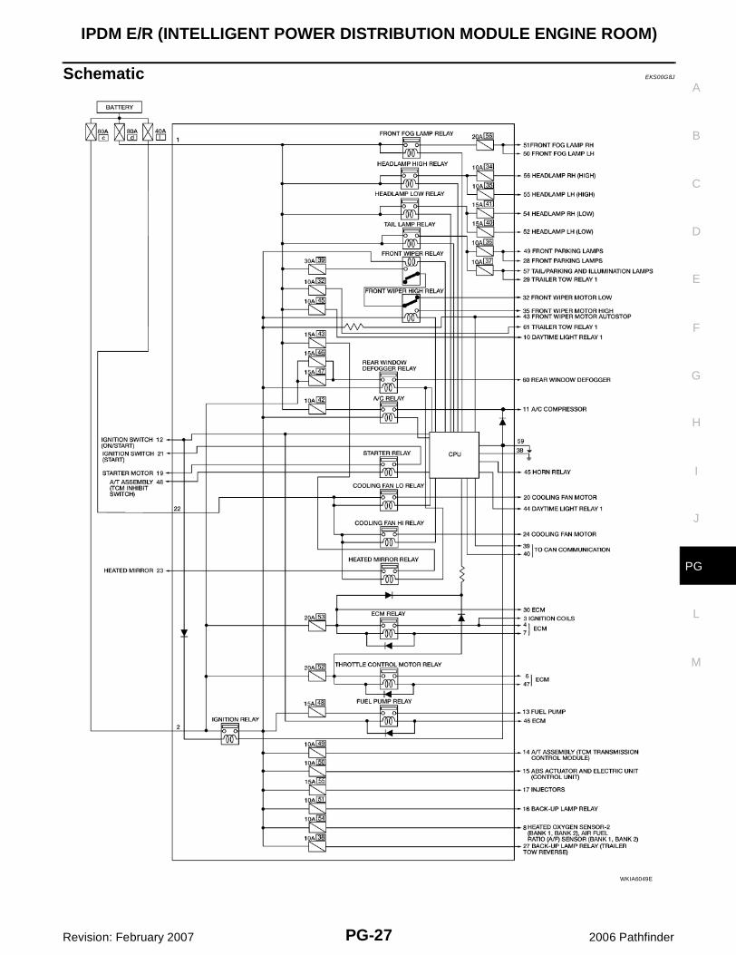
Schematic EKS00G8J
WKIA6049E
PG-28
IPDM E/R (INTELLIGENT POWER DISTRIBUTION MODULE ENGINE ROOM)
Revision: February 2007 2006 Pathfinder
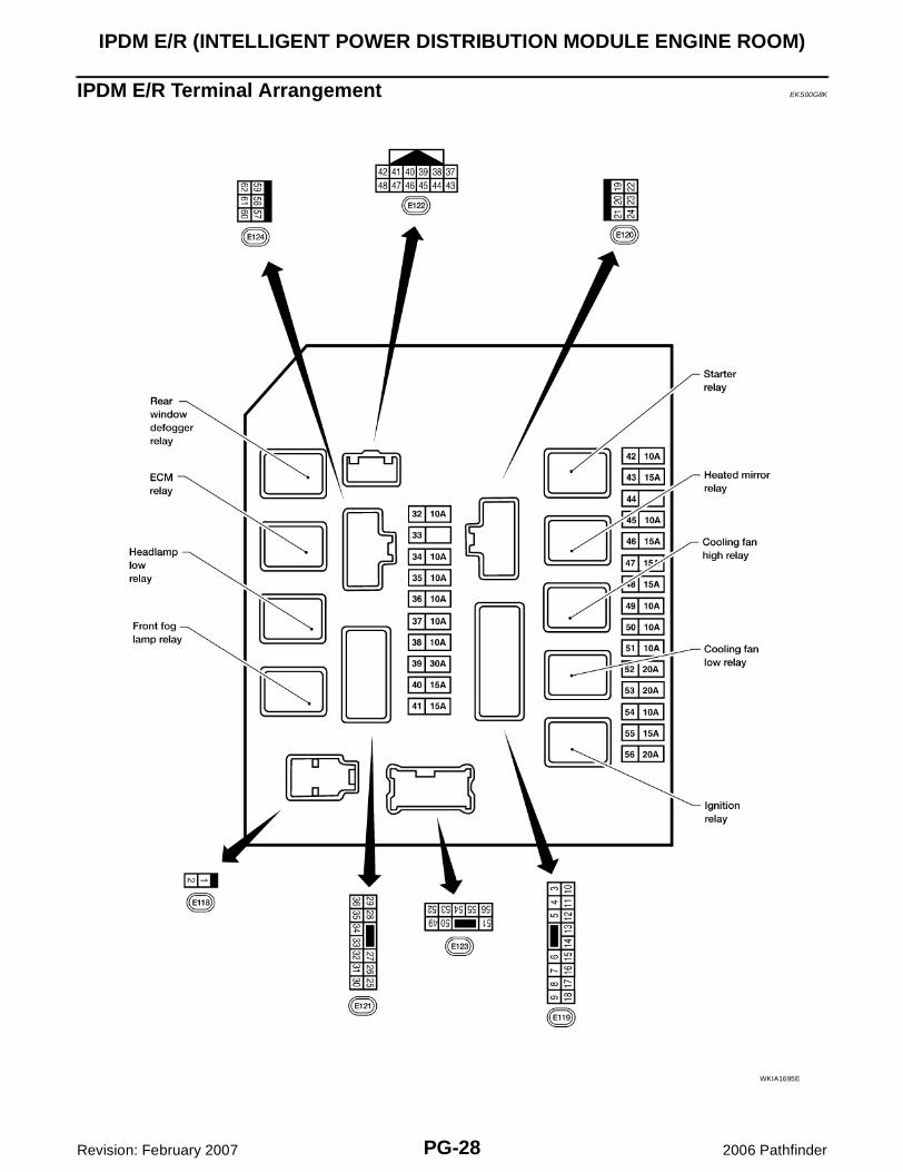
IPDM E/R Terminal Arrangement EKS00G8K
WKIA1695E
IPDM E/R (INTELLIGENT POWER DISTRIBUTION MODULE ENGINE ROOM)
PG-29
C
D
E
F
G
H
I
J
L
M
A
B
PG
Revision: February 2007 2006 Pathfinder
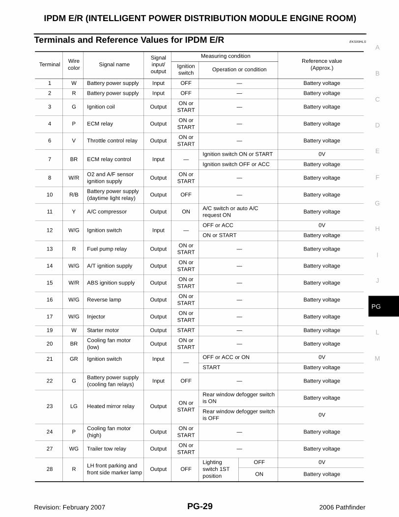
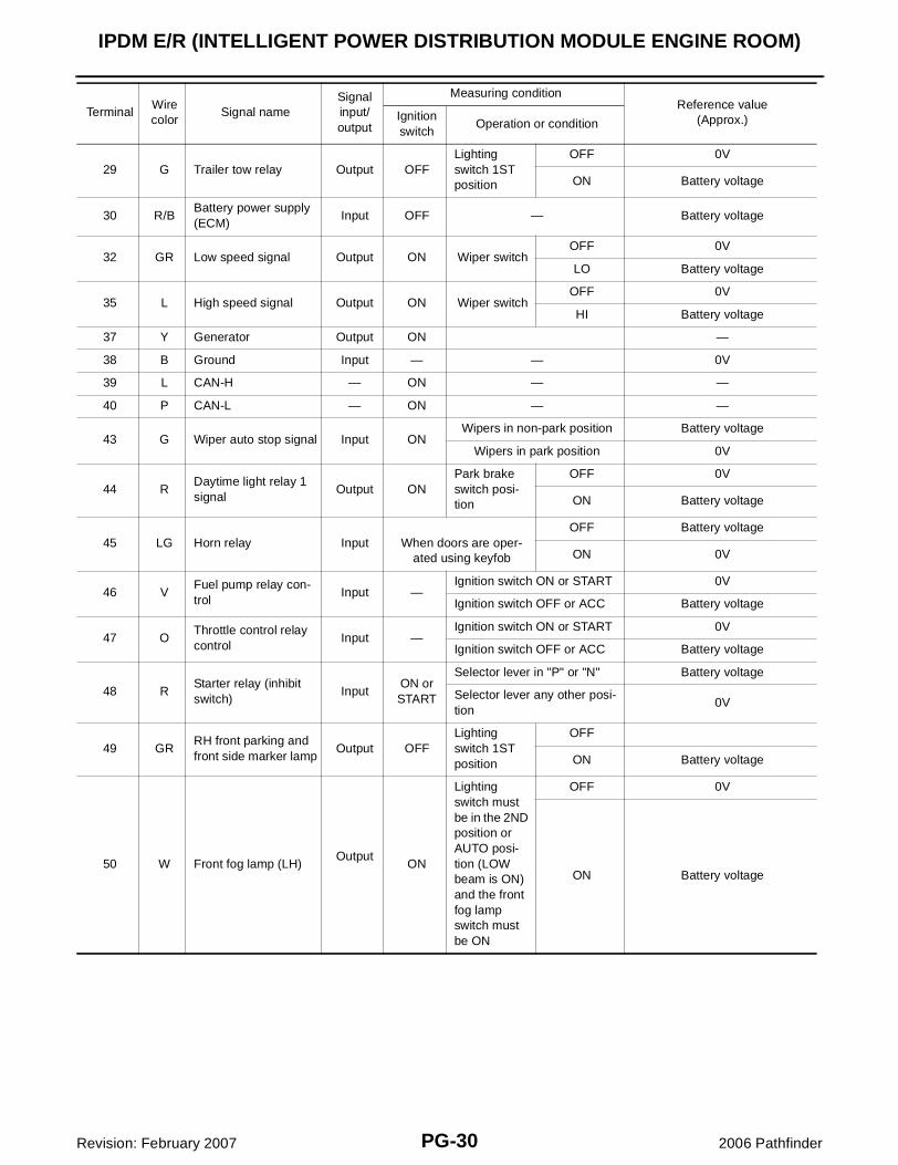
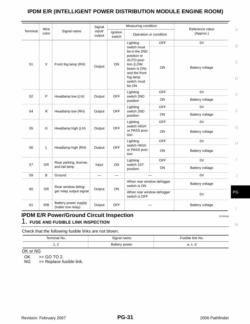
Terminals and Reference Values for IPDM E/R EKS00HLS
TerminalWire color
Signal nameSignal input/output
Measuring conditionReference value
(Approx.)Ignition switch
Operation or condition
1 W Battery power supply Input OFF — Battery voltage
2 R Battery power supply Input OFF — Battery voltage
3 G Ignition coil OutputON or START
— Battery voltage
4 P ECM relay OutputON or START
— Battery voltage
6 V Throttle control relay OutputON or START
— Battery voltage
7 BR ECM relay control Input —Ignition switch ON or START 0V
Ignition switch OFF or ACC Battery voltage
8 W/RO2 and A/F sensor ignition supply
OutputON or START
— Battery voltage
10 R/BBattery power supply (daytime light relay)
Output OFF — Battery voltage
11 Y A/C compressor Output ONA/C switch or auto A/C request ON
Battery voltage
12 W/G Ignition switch Input —OFF or ACC 0V
ON or START Battery voltage
13 R Fuel pump relay OutputON or START
— Battery voltage
14 W/G A/T ignition supply OutputON or START
— Battery voltage
15 W/R ABS ignition supply OutputON or START
— Battery voltage
16 W/G Reverse lamp OutputON or START
— Battery voltage
17 W/G Injector OutputON or START
— Battery voltage
19 W Starter motor Output START — Battery voltage
20 BRCooling fan motor (low)
OutputON or START
— Battery voltage
21 GR Ignition switch Input—
OFF or ACC or ON 0V
START Battery voltage
22 GBattery power supply (cooling fan relays)
Input OFF — Battery voltage
23 LG Heated mirror relay OutputON or START
Rear window defogger switch is ON
Battery voltage
Rear window defogger switch is OFF
0V
24 PCooling fan motor (high)
OutputON or START
— Battery voltage
27 WG Trailer tow relay OutputON or START
— Battery voltage
28 RLH front parking and front side marker lamp
Output OFFLighting switch 1ST position
OFF 0V
ON Battery voltage
PG-30
IPDM E/R (INTELLIGENT POWER DISTRIBUTION MODULE ENGINE ROOM)
Revision: February 2007 2006 Pathfinder
29 G Trailer tow relay Output OFFLighting switch 1ST position
OFF 0V
ON Battery voltage
30 R/BBattery power supply (ECM)
Input OFF — Battery voltage
32 GR Low speed signal Output ON Wiper switchOFF 0V
LO Battery voltage
35 L High speed signal Output ON Wiper switchOFF 0V
HI Battery voltage
37 Y Generator Output ON —
38 B Ground Input — — 0V
39 L CAN-H — ON — —
40 P CAN-L — ON — —
43 G Wiper auto stop signal Input ONWipers in non-park position Battery voltage
Wipers in park position 0V
44 RDaytime light relay 1 signal
Output ONPark brake switch posi-tion
OFF 0V
ON Battery voltage
45 LG Horn relay Input When doors are oper-ated using keyfob
OFF Battery voltage
ON 0V
46 VFuel pump relay con-trol
Input —Ignition switch ON or START 0V
Ignition switch OFF or ACC Battery voltage
47 OThrottle control relay control
Input —Ignition switch ON or START 0V
Ignition switch OFF or ACC Battery voltage
48 RStarter relay (inhibit switch)
InputON or START
Selector lever in "P" or "N" Battery voltage
Selector lever any other posi-tion
0V
49 GRRH front parking and front side marker lamp
Output OFFLighting switch 1ST position
OFF
ON Battery voltage
50 W Front fog lamp (LH)Output
ON
Lighting switch must be in the 2ND position or AUTO posi-tion (LOW beam is ON) and the front fog lamp switch must be ON
OFF 0V
ON Battery voltage
TerminalWire color
Signal nameSignal input/output
Measuring conditionReference value
(Approx.)Ignition switch
Operation or condition
IPDM E/R (INTELLIGENT POWER DISTRIBUTION MODULE ENGINE ROOM)
PG-31
C
D
E
F
G
H
I
J
L
M
A
B
PG
Revision: February 2007 2006 Pathfinder
IPDM E/R Power/Ground Circuit Inspection EKS00G8L
1. FUSE AND FUSIBLE LINK INSPECTION
Check that the following fusible links are not blown.
OK or NGOK >> GO TO 2.NG >> Replace fusible link.
51 V Front fog lamp (RH) Output
ON
Lighting switch must be in the 2ND position or AUTO posi-tion (LOW beam is ON) and the front fog lamp switch must be ON
OFF 0V
ON Battery voltage
52 P Headlamp low (LH) Output OFFLighting switch 2ND position
OFF 0V
ON Battery voltage
54 R Headlamp low (RH) Output OFFLighting switch 2ND position
OFF 0V
ON Battery voltage
55 G Headlamp high (LH) Output OFF
Lighting switch HIGH or PASS posi-tion
OFF 0V
ON Battery voltage
56 L Headlamp high (RH) Output OFF
Lighting switch HIGH or PASS posi-tion
OFF 0V
ON Battery voltage
57 GRRear parking, license, and tail lamp
Input ONLighting switch 1ST position
OFF 0V
ON Battery voltage
59 B Ground — — — 0V
60 GRRear window defog-ger relay output signal
Output ON
When rear window defogger switch is ON
Battery voltage
When rear window defogger switch is OFF
0V
61 R/BBattery power supply (trailer tow relay)
Output OFF — Battery voltage
TerminalWire color
Signal nameSignal input/output
Measuring conditionReference value
(Approx.)Ignition switch
Operation or condition
Terminal No. Signal name Fusible link No.
1, 2 Battery power a, c, d
PG-32
IPDM E/R (INTELLIGENT POWER DISTRIBUTION MODULE ENGINE ROOM)
Revision: February 2007 2006 Pathfinder
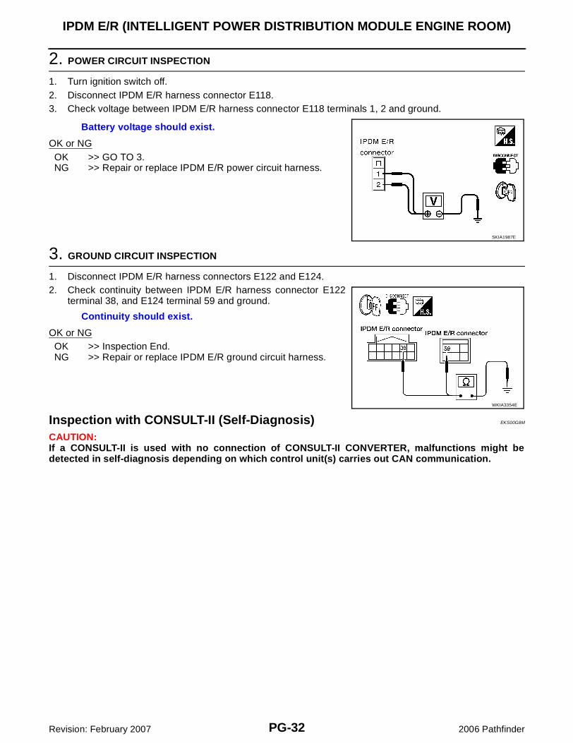
2. POWER CIRCUIT INSPECTION
1. Turn ignition switch off.2. Disconnect IPDM E/R harness connector E118.3. Check voltage between IPDM E/R harness connector E118 terminals 1, 2 and ground.
OK or NGOK >> GO TO 3.NG >> Repair or replace IPDM E/R power circuit harness.
3. GROUND CIRCUIT INSPECTION
1. Disconnect IPDM E/R harness connectors E122 and E124.2. Check continuity between IPDM E/R harness connector E122
terminal 38, and E124 terminal 59 and ground.
OK or NGOK >> Inspection End.NG >> Repair or replace IPDM E/R ground circuit harness.
Inspection with CONSULT-II (Self-Diagnosis) EKS00G8M
CAUTION:If a CONSULT-II is used with no connection of CONSULT-II CONVERTER, malfunctions might bedetected in self-diagnosis depending on which control unit(s) carries out CAN communication.
Battery voltage should exist.
SKIA1987E
Continuity should exist.
WKIA3354E
IPDM E/R (INTELLIGENT POWER DISTRIBUTION MODULE ENGINE ROOM)
PG-33
C
D
E
F
G
H
I
J
L
M
A
B
PG
Revision: February 2007 2006 Pathfinder
1. SELF-DIAGNOSIS RESULT CHECK
1. Connect CONSULT-II and select "IPDM E/R" on the "SELECT SYSTEM".2. Select "SELF-DIAG RESULTS" on the "SELECT DIAG MODE" screen.3. Check display content in self-diagnosis results.
NOTE:The Details for Display for the Period are as follows:� CRNT: Error currently detected by IPDM E/R.� PAST: Error detected in the past and stored in IPDM E/R memory.Contents displayedNO DTC DETECTED. FURTHER TESTING MAY BE REQUIRED.>>INSPECTION END.CAN COMM CIRC>>Print out the self-diagnosis result and refer to LAN-25, "CAN COMMUNICATION" .
CONSULT-II DisplayCONSULT-II display code
TIMEDetails of diagnosis result
CRNT PAST
NO DTC IS DETECTED.FURTHER TESTING MAY BE REQUIRED.
— — — No malfunction
CAN COMM CIRC U1000 X X
Any of items listed below have errors:
� TRANSMIT DIAG
� ECM
� BCM/SEC
PG-34
IPDM E/R (INTELLIGENT POWER DISTRIBUTION MODULE ENGINE ROOM)
Revision: February 2007 2006 Pathfinder
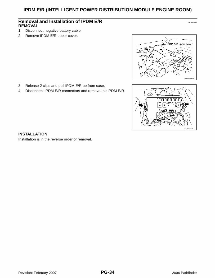
Removal and Installation of IPDM E/R EKS00G8N
REMOVAL1. Disconnect negative battery cable.2. Remove IPDM E/R upper cover.
3. Release 2 clips and pull IPDM E/R up from case.4. Disconnect IPDM E/R connectors and remove the IPDM E/R.
INSTALLATIONInstallation is in the reverse order of removal.
WKIA3352E
LKIA0421E
GROUND CIRCUIT
PG-35
C
D
E
F
G
H
I
J
L
M
A
B
PG
Revision: February 2007 2006 Pathfinder
GROUND CIRCUIT PFP:24080
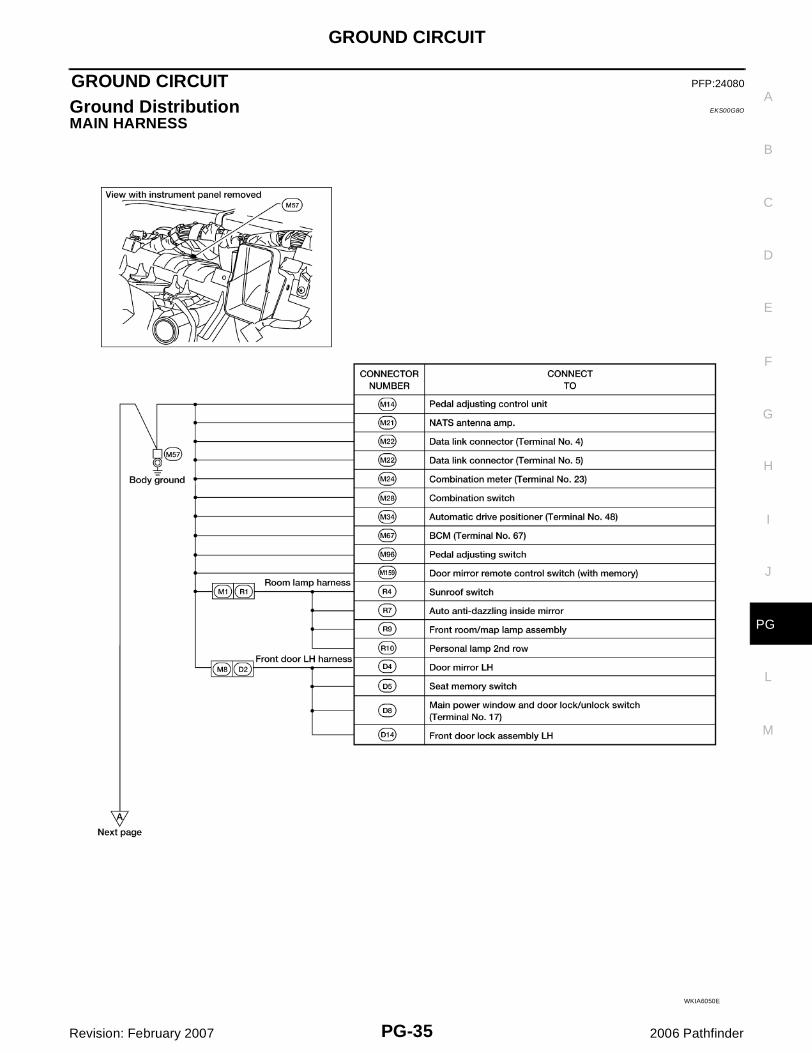
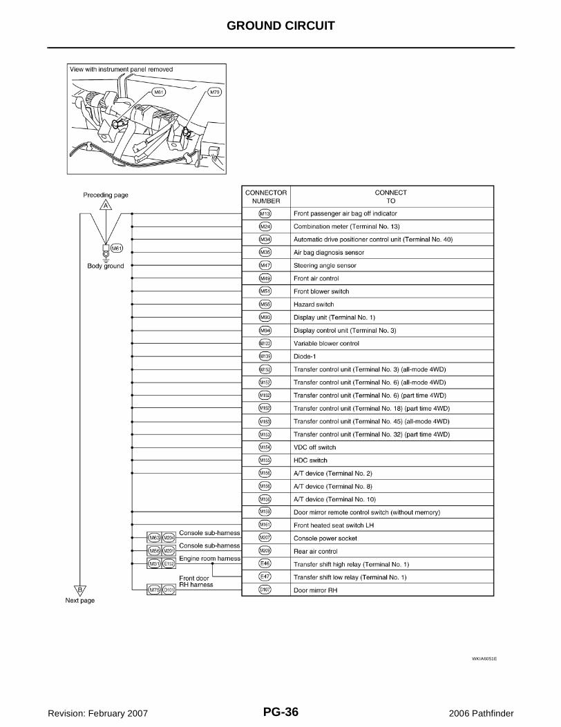
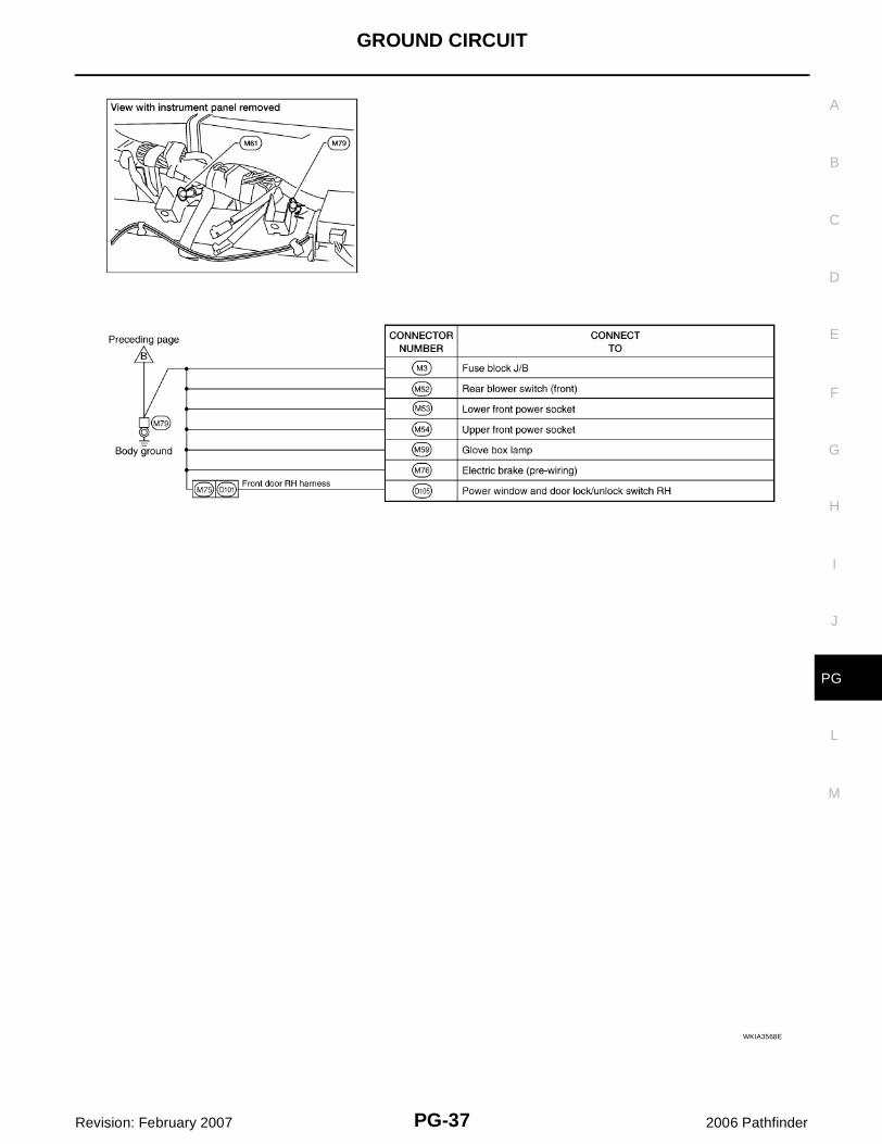
Ground Distribution EKS00G8O
MAIN HARNESS
WKIA6050E
PG-36
GROUND CIRCUIT
Revision: February 2007 2006 Pathfinder
WKIA6051E
GROUND CIRCUIT
PG-37
C
D
E
F
G
H
I
J
L
M
A
B
PG
Revision: February 2007 2006 Pathfinder
WKIA3568E
PG-38
GROUND CIRCUIT
Revision: February 2007 2006 Pathfinder
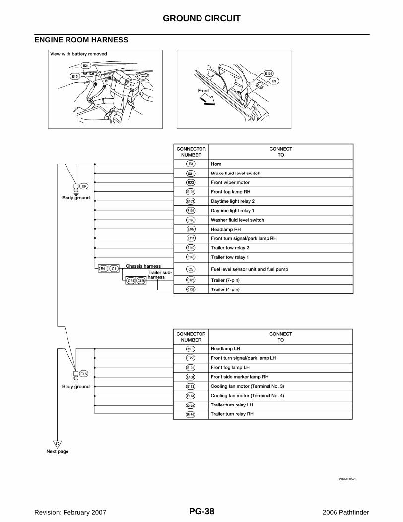
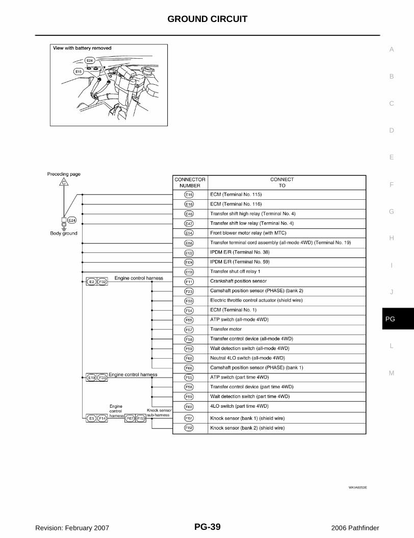
ENGINE ROOM HARNESS
WKIA6052E
GROUND CIRCUIT
PG-39
C
D
E
F
G
H
I
J
L
M
A
B
PG
Revision: February 2007 2006 Pathfinder
WKIA6053E
PG-40
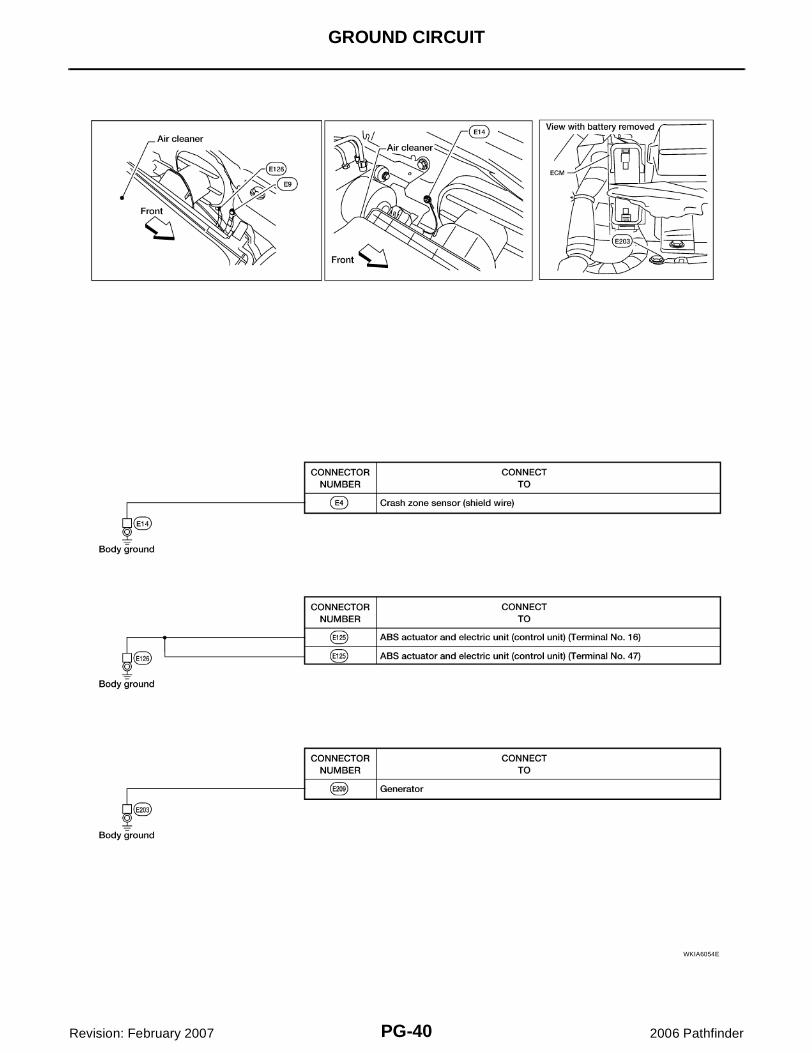
GROUND CIRCUIT
Revision: February 2007 2006 Pathfinder
WKIA6054E
GROUND CIRCUIT
PG-41
C
D
E
F
G
H
I
J
L
M
A
B
PG
Revision: February 2007 2006 Pathfinder
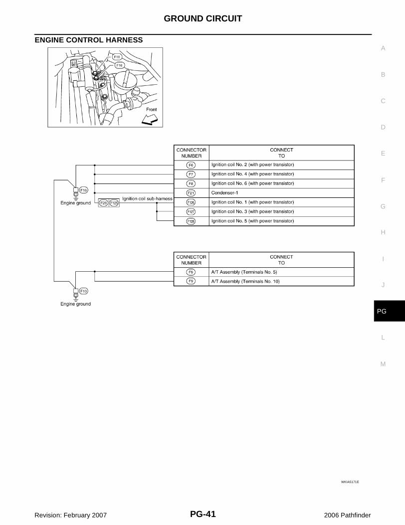
ENGINE CONTROL HARNESS
WKIA5171E
PG-42
GROUND CIRCUIT
Revision: February 2007 2006 Pathfinder
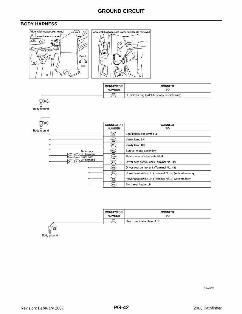
BODY HARNESS
WKIA6055E
GROUND CIRCUIT
PG-43
C
D
E
F
G
H
I
J
L
M
A
B
PG
Revision: February 2007 2006 Pathfinder
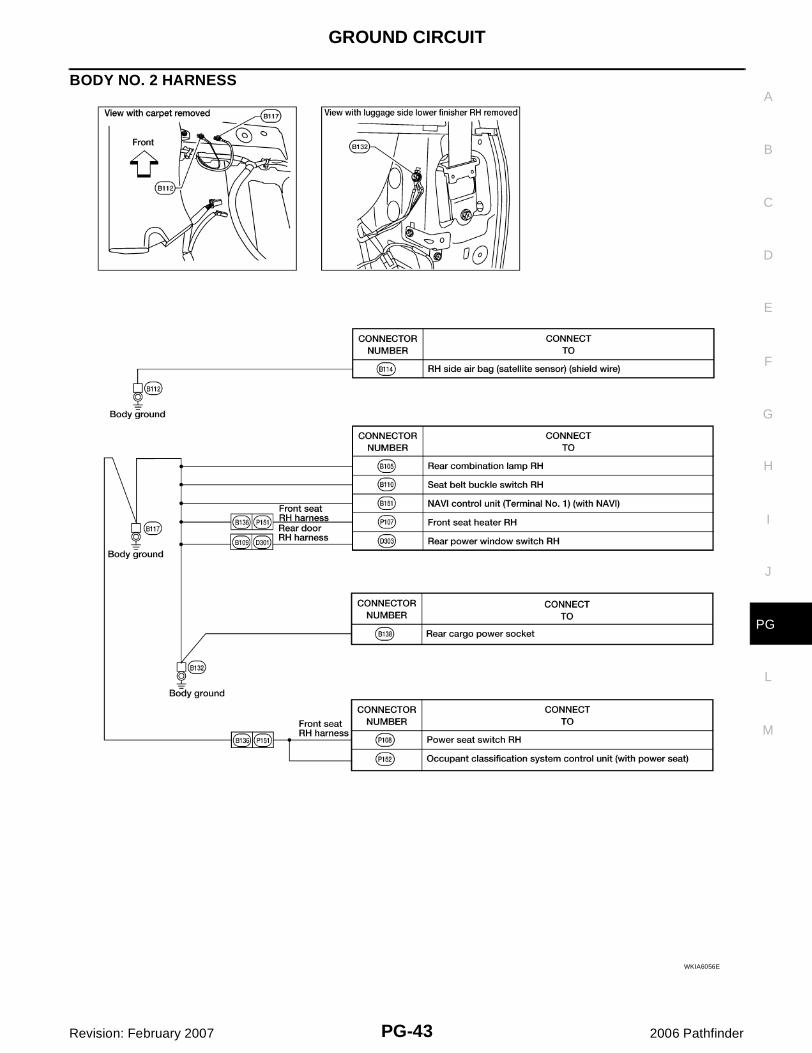
BODY NO. 2 HARNESS
WKIA6056E
PG-44
GROUND CIRCUIT
Revision: February 2007 2006 Pathfinder
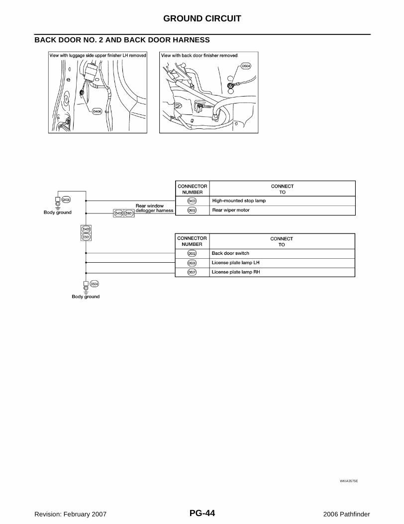
BACK DOOR NO. 2 AND BACK DOOR HARNESS
WKIA3575E
HARNESS
PG-45
C
D
E
F
G
H
I
J
L
M
A
B
PG
Revision: February 2007 2006 Pathfinder
HARNESS PFP:24010
Harness Layout EKS00G8P
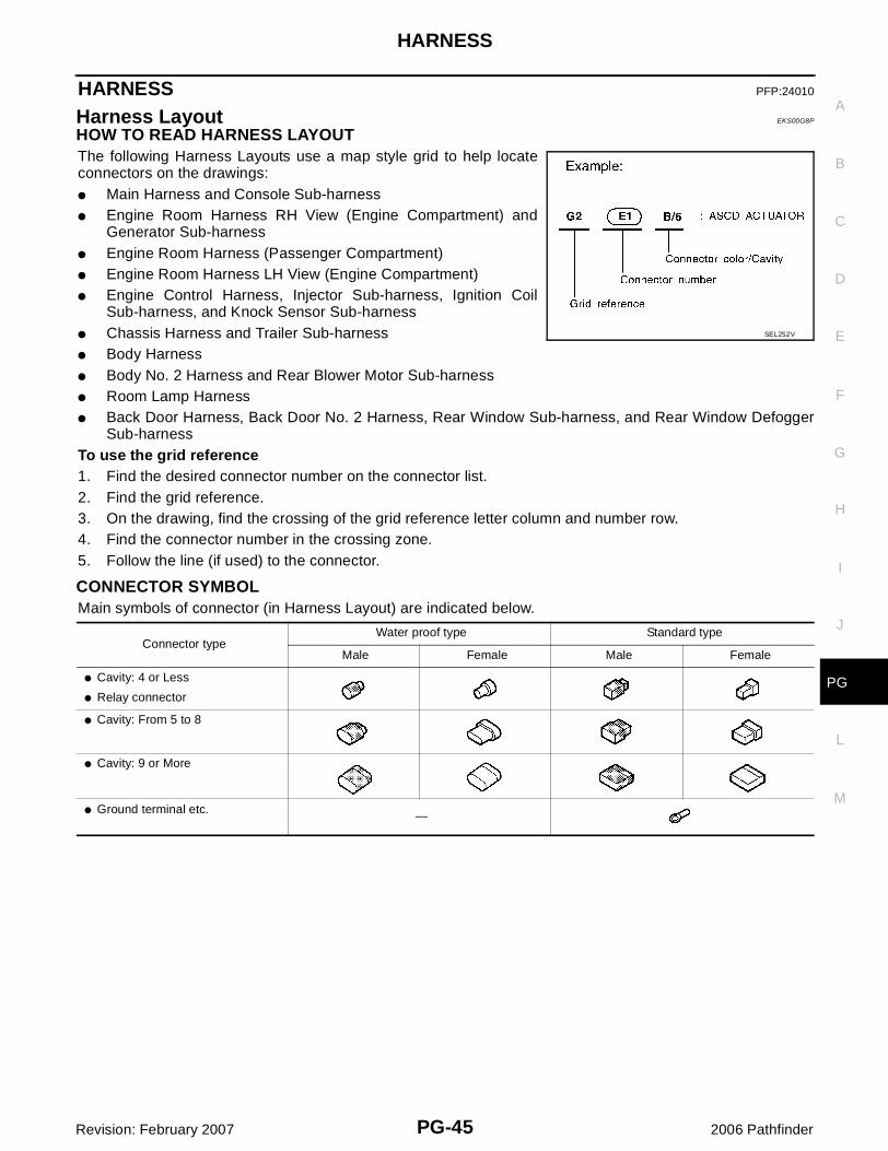
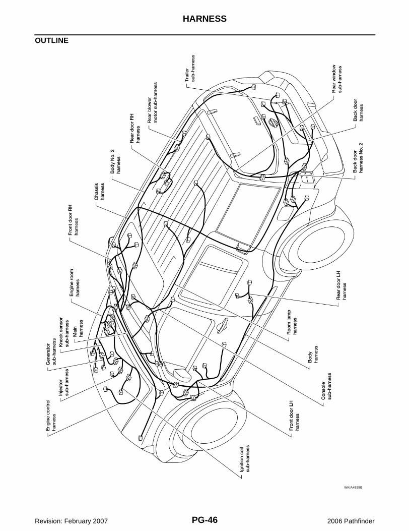
HOW TO READ HARNESS LAYOUT The following Harness Layouts use a map style grid to help locateconnectors on the drawings:� Main Harness and Console Sub-harness� Engine Room Harness RH View (Engine Compartment) and
Generator Sub-harness� Engine Room Harness (Passenger Compartment)� Engine Room Harness LH View (Engine Compartment)� Engine Control Harness, Injector Sub-harness, Ignition Coil
Sub-harness, and Knock Sensor Sub-harness� Chassis Harness and Trailer Sub-harness� Body Harness� Body No. 2 Harness and Rear Blower Motor Sub-harness� Room Lamp Harness� Back Door Harness, Back Door No. 2 Harness, Rear Window Sub-harness, and Rear Window Defogger
Sub-harnessTo use the grid reference1. Find the desired connector number on the connector list.2. Find the grid reference.3. On the drawing, find the crossing of the grid reference letter column and number row.4. Find the connector number in the crossing zone.5. Follow the line (if used) to the connector.
CONNECTOR SYMBOLMain symbols of connector (in Harness Layout) are indicated below.
SEL252V
Connector typeWater proof type Standard type
Male Female Male Female
� Cavity: 4 or Less
� Relay connector
� Cavity: From 5 to 8
� Cavity: 9 or More
� Ground terminal etc. —
PG-46
HARNESS
Revision: February 2007 2006 Pathfinder
OUTLINE
WKIA4999E
HARNESS
PG-47
C
D
E
F
G
H
I
J
L
M
A
B
PG
Revision: February 2007 2006 Pathfinder
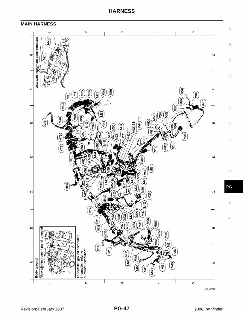
MAIN HARNESS
WKIA6057E
PG-48
HARNESS
Revision: February 2007 2006 Pathfinder
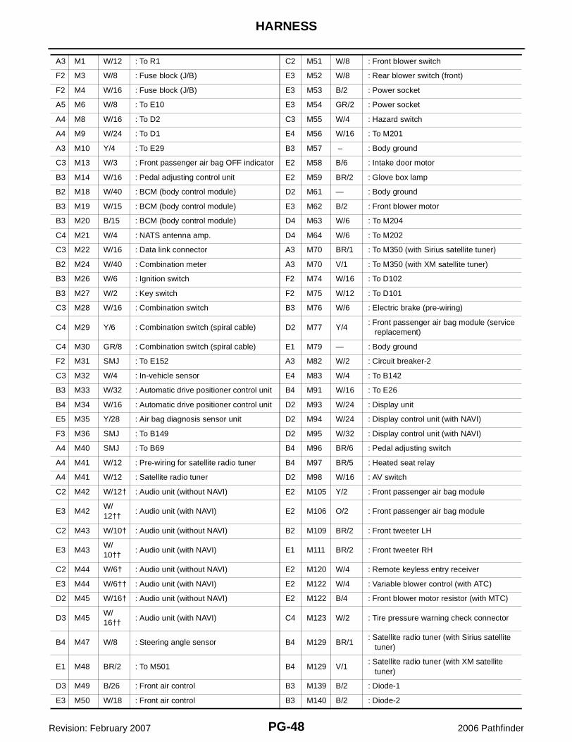
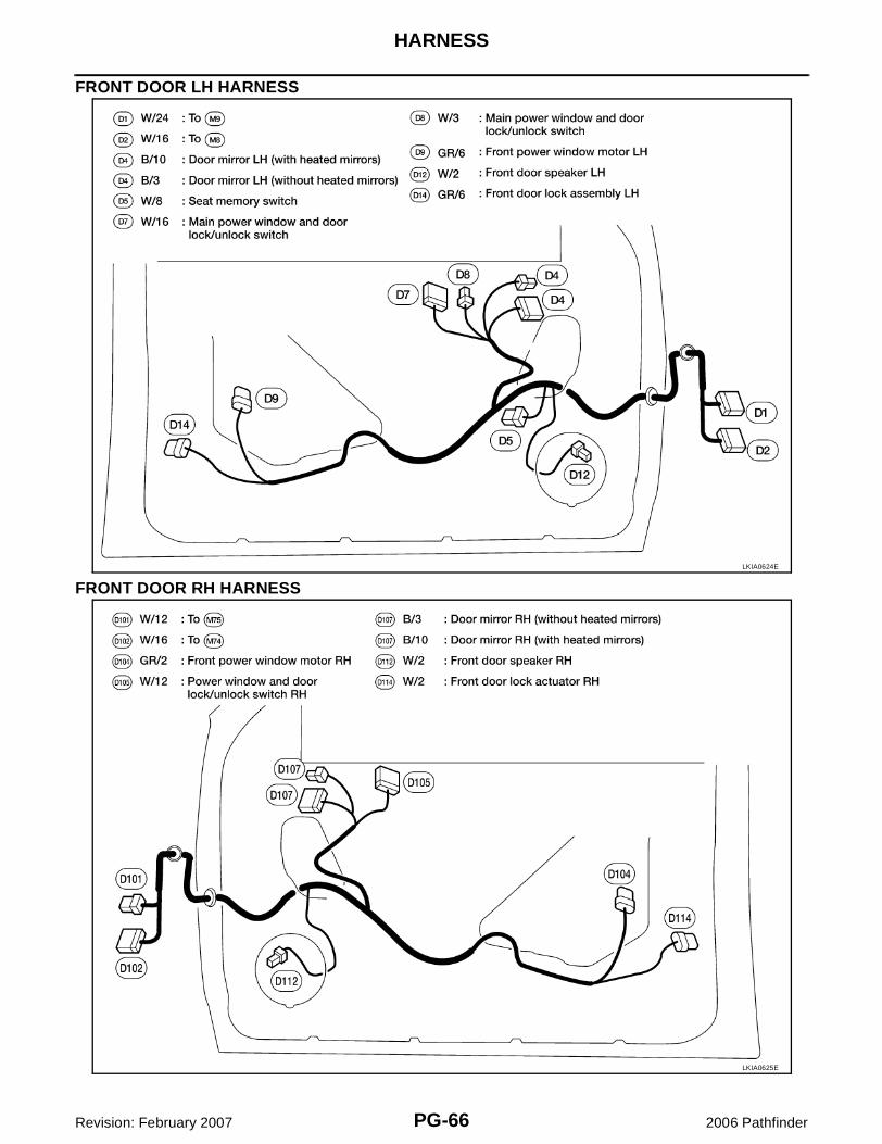
A3 M1 W/12 : To R1 C2 M51 W/8 : Front blower switch
F2 M3 W/8 : Fuse block (J/B) E3 M52 W/8 : Rear blower switch (front)
F2 M4 W/16 : Fuse block (J/B) E3 M53 B/2 : Power socket
A5 M6 W/8 : To E10 E3 M54 GR/2 : Power socket
A4 M8 W/16 : To D2 C3 M55 W/4 : Hazard switch
A4 M9 W/24 : To D1 E4 M56 W/16 : To M201
A3 M10 Y/4 : To E29 B3 M57 – : Body ground
C3 M13 W/3 : Front passenger air bag OFF indicator E2 M58 B/6 : Intake door motor
B3 M14 W/16 : Pedal adjusting control unit E2 M59 BR/2 : Glove box lamp
B2 M18 W/40 : BCM (body control module) D2 M61 — : Body ground
B3 M19 W/15 : BCM (body control module) E3 M62 B/2 : Front blower motor
B3 M20 B/15 : BCM (body control module) D4 M63 W/6 : To M204
C4 M21 W/4 : NATS antenna amp. D4 M64 W/6 : To M202
C3 M22 W/16 : Data link connector A3 M70 BR/1 : To M350 (with Sirius satellite tuner)
B2 M24 W/40 : Combination meter A3 M70 V/1 : To M350 (with XM satellite tuner)
B3 M26 W/6 : Ignition switch F2 M74 W/16 : To D102
B3 M27 W/2 : Key switch F2 M75 W/12 : To D101
C3 M28 W/16 : Combination switch B3 M76 W/6 : Electric brake (pre-wiring)
C4 M29 Y/6 : Combination switch (spiral cable) D2 M77 Y/4: Front passenger air bag module (service replacement)
C4 M30 GR/8 : Combination switch (spiral cable) E1 M79 — : Body ground
F2 M31 SMJ : To E152 A3 M82 W/2 : Circuit breaker-2
C3 M32 W/4 : In-vehicle sensor E4 M83 W/4 : To B142
B3 M33 W/32 : Automatic drive positioner control unit B4 M91 W/16 : To E26
B4 M34 W/16 : Automatic drive positioner control unit D2 M93 W/24 : Display unit
E5 M35 Y/28 : Air bag diagnosis sensor unit D2 M94 W/24 : Display control unit (with NAVI)
F3 M36 SMJ : To B149 D2 M95 W/32 : Display control unit (with NAVI)
A4 M40 SMJ : To B69 B4 M96 BR/6 : Pedal adjusting switch
A4 M41 W/12 : Pre-wiring for satellite radio tuner B4 M97 BR/5 : Heated seat relay
A4 M41 W/12 : Satellite radio tuner D2 M98 W/16 : AV switch
C2 M42 W/12† : Audio unit (without NAVI) E2 M105 Y/2 : Front passenger air bag module
E3 M42W/12††
: Audio unit (with NAVI) E2 M106 O/2 : Front passenger air bag module
C2 M43 W/10† : Audio unit (without NAVI) B2 M109 BR/2 : Front tweeter LH
E3 M43W/10††
: Audio unit (with NAVI) E1 M111 BR/2 : Front tweeter RH
C2 M44 W/6† : Audio unit (without NAVI) E2 M120 W/4 : Remote keyless entry receiver
E3 M44 W/6†† : Audio unit (with NAVI) E2 M122 W/4 : Variable blower control (with ATC)
D2 M45 W/16† : Audio unit (without NAVI) E2 M122 B/4 : Front blower motor resistor (with MTC)
D3 M45W/16††
: Audio unit (with NAVI) C4 M123 W/2 : Tire pressure warning check connector
B4 M47 W/8 : Steering angle sensor B4 M129 BR/1: Satellite radio tuner (with Sirius satellite tuner)
E1 M48 BR/2 : To M501 B4 M129 V/1: Satellite radio tuner (with XM satellite tuner)
D3 M49 B/26 : Front air control B3 M139 B/2 : Diode-1
E3 M50 W/18 : Front air control B3 M140 B/2 : Diode-2
HARNESS
PG-49
C
D
E
F
G
H
I
J
L
M
A
B
PG
Revision: February 2007 2006 Pathfinder
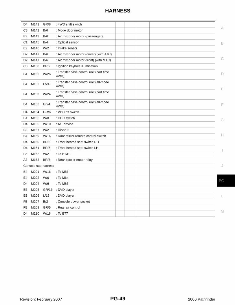
D4 M141 GR/8 : 4WD shift switch
C3 M142 B/6 : Mode door motor
E3 M143 B/6 : Air mix door motor (passenger)
C1 M145 B/4 : Optical sensor
E2 M146 W/2 : Intake sensor
D2 M147 B/6 : Air mix door motor (driver) (with ATC)
D2 M147 B/6 : Air mix door motor (front) (with MTC)
C3 M150 BR/2 : Ignition keyhole illumination
B4 M152 W/26: Transfer case control unit (part time 4WD)
B4 M152 L/24: Transfer case control unit (all-mode 4WD)
B4 M153 W/24: Transfer case control unit (part time 4WD)
B4 M153 G/24: Transfer case control unit (all-mode 4WD)
D4 M154 GR/6 : VDC off switch
E4 M155 W/8 : HDC switch
D4 M156 W/10 : A/T device
B2 M157 W/2 : Diode-5
B4 M159 W/16 : Door mirror remote control switch
D4 M160 BR/6 : Front heated seat switch RH
D4 M161 BR/6 : Front heated seat switch LH
F2 M162 W/2 : To B131
A3 M163 BR/6 : Rear blower motor relay
Console sub-harness
E4 M201 W/16 : To M56
E4 M202 W/6 : To M64
D4 M204 W/6 : To M63
E5 M205 GR/16 : DVD player
E5 M206 L/16 : DVD player
F5 M207 B/2 : Console power socket
F5 M208 GR/5 : Rear air control
D4 M210 W/18 : To B77
PG-50
HARNESS
Revision: February 2007 2006 Pathfinder
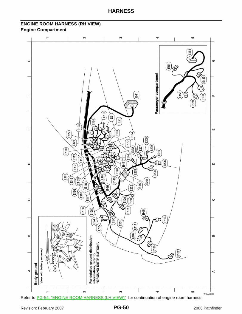
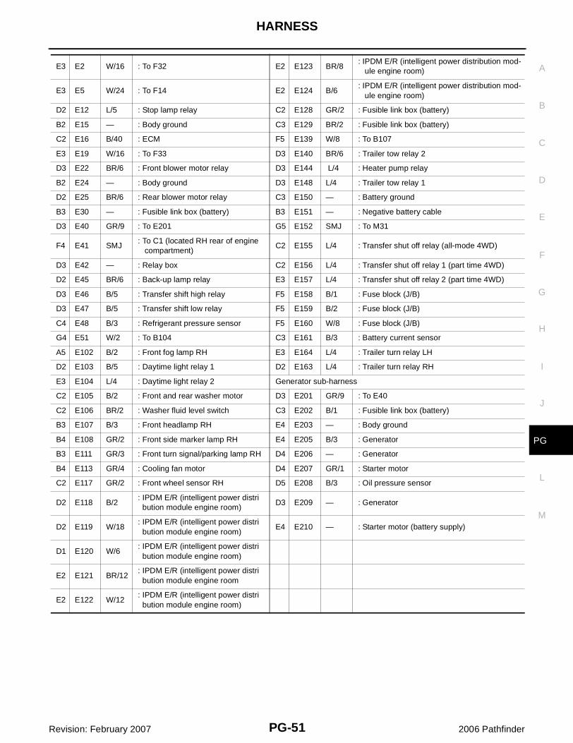
ENGINE ROOM HARNESS (RH VIEW)Engine Compartment
Refer to PG-54, "ENGINE ROOM HARNESS (LH VIEW)" for continuation of engine room harness.WKIA6058E
HARNESS
PG-51
C
D
E
F
G
H
I
J
L
M
A
B
PG
Revision: February 2007 2006 Pathfinder
E3 E2 W/16 : To F32 E2 E123 BR/8: IPDM E/R (intelligent power distribution mod- ule engine room)
E3 E5 W/24 : To F14 E2 E124 B/6: IPDM E/R (intelligent power distribution mod- ule engine room)
D2 E12 L/5 : Stop lamp relay C2 E128 GR/2 : Fusible link box (battery)
B2 E15 — : Body ground C3 E129 BR/2 : Fusible link box (battery)
C2 E16 B/40 : ECM F5 E139 W/8 : To B107
E3 E19 W/16 : To F33 D3 E140 BR/6 : Trailer tow relay 2
D3 E22 BR/6 : Front blower motor relay D3 E144 L/4 : Heater pump relay
B2 E24 — : Body ground D3 E148 L/4 : Trailer tow relay 1
D2 E25 BR/6 : Rear blower motor relay C3 E150 — : Battery ground
B3 E30 — : Fusible link box (battery) B3 E151 — : Negative battery cable
D3 E40 GR/9 : To E201 G5 E152 SMJ : To M31
F4 E41 SMJ: To C1 (located RH rear of engine compartment)
C2 E155 L/4 : Transfer shut off relay (all-mode 4WD)
D3 E42 — : Relay box C2 E156 L/4 : Transfer shut off relay 1 (part time 4WD)
D2 E45 BR/6 : Back-up lamp relay E3 E157 L/4 : Transfer shut off relay 2 (part time 4WD)
D3 E46 B/5 : Transfer shift high relay F5 E158 B/1 : Fuse block (J/B)
D3 E47 B/5 : Transfer shift low relay F5 E159 B/2 : Fuse block (J/B)
C4 E48 B/3 : Refrigerant pressure sensor F5 E160 W/8 : Fuse block (J/B)
G4 E51 W/2 : To B104 C3 E161 B/3 : Battery current sensor
A5 E102 B/2 : Front fog lamp RH E3 E164 L/4 : Trailer turn relay LH
D2 E103 B/5 : Daytime light relay 1 D2 E163 L/4 : Trailer turn relay RH
E3 E104 L/4 : Daytime light relay 2 Generator sub-harness
C2 E105 B/2 : Front and rear washer motor D3 E201 GR/9 : To E40
C2 E106 BR/2 : Washer fluid level switch C3 E202 B/1 : Fusible link box (battery)
B3 E107 B/3 : Front headlamp RH E4 E203 — : Body ground
B4 E108 GR/2 : Front side marker lamp RH E4 E205 B/3 : Generator
B3 E111 GR/3 : Front turn signal/parking lamp RH D4 E206 — : Generator
B4 E113 GR/4 : Cooling fan motor D4 E207 GR/1 : Starter motor
C2 E117 GR/2 : Front wheel sensor RH D5 E208 B/3 : Oil pressure sensor
D2 E118 B/2: IPDM E/R (intelligent power distri bution module engine room)
D3 E209 — : Generator
D2 E119 W/18: IPDM E/R (intelligent power distri bution module engine room)
E4 E210 — : Starter motor (battery supply)
D1 E120 W/6: IPDM E/R (intelligent power distri bution module engine room)
E2 E121 BR/12: IPDM E/R (intelligent power distri bution module engine room
E2 E122 W/12: IPDM E/R (intelligent power distri bution module engine room)
PG-52
HARNESS
Revision: February 2007 2006 Pathfinder
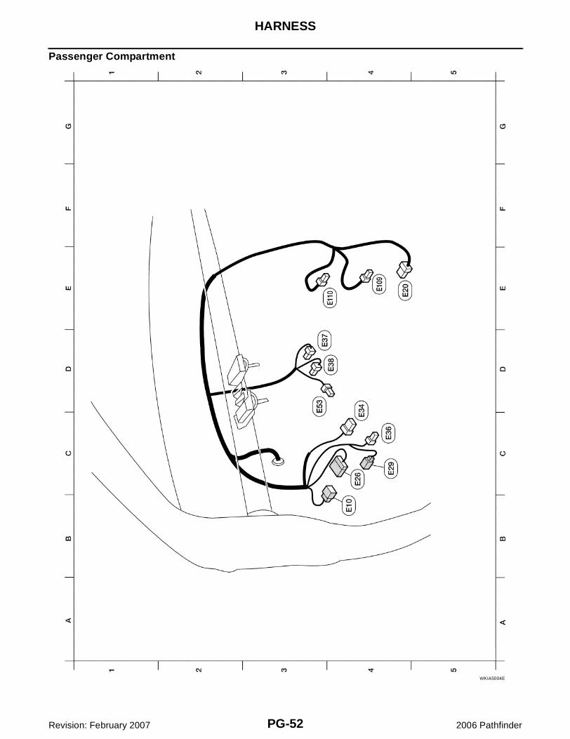
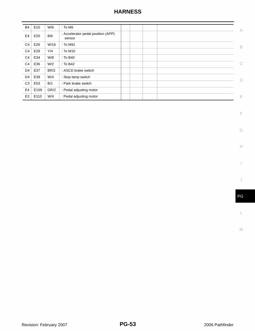
Passenger Compartment
WKIA5004E
HARNESS
PG-53
C
D
E
F
G
H
I
J
L
M
A
B
PG
Revision: February 2007 2006 Pathfinder
B4 E10 W/6 : To M6
E4 E20 B/6: Accelerator pedal position (APP) sensor
C4 E26 W/16 : To M91
C4 E29 Y/4 : To M10
C4 E34 W/8 : To B40
C4 E36 W/2 : To B42
D4 E37 BR/2 : ASCD brake switch
D4 E38 W/4 : Stop lamp switch
C3 E53 B/1 : Park brake switch
E4 E109 GR/2 : Pedal adjusting motor
E3 E110 W/4 : Pedal adjusting motor
PG-54
HARNESS
Revision: February 2007 2006 Pathfinder
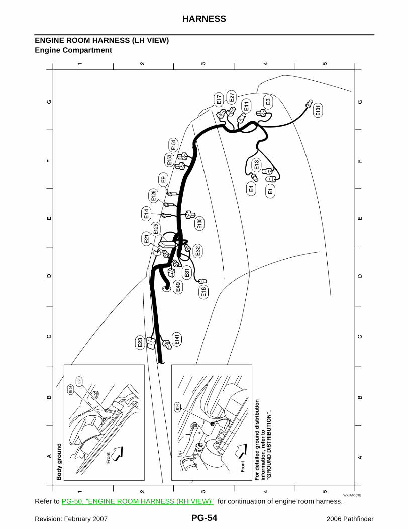
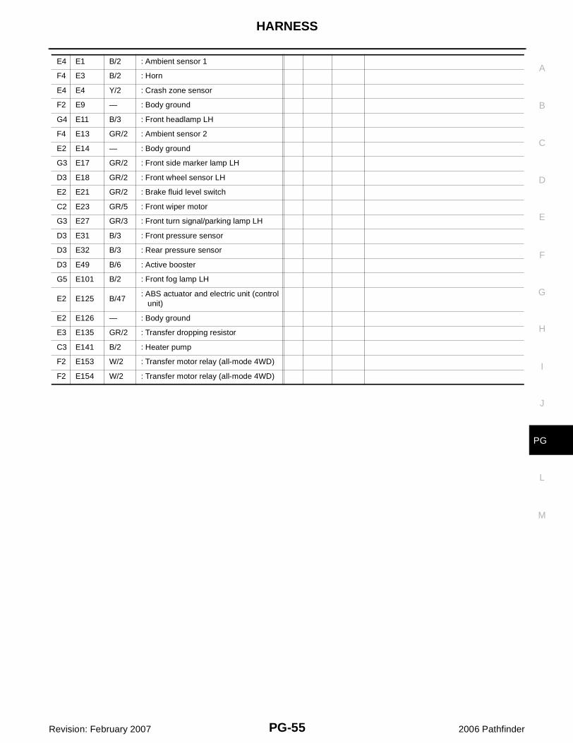
ENGINE ROOM HARNESS (LH VIEW)Engine Compartment
Refer to PG-50, "ENGINE ROOM HARNESS (RH VIEW)" for continuation of engine room harness.WKIA6059E
HARNESS
PG-55
C
D
E
F
G
H
I
J
L
M
A
B
PG
Revision: February 2007 2006 Pathfinder
E4 E1 B/2 : Ambient sensor 1
F4 E3 B/2 : Horn
E4 E4 Y/2 : Crash zone sensor
F2 E9 — : Body ground
G4 E11 B/3 : Front headlamp LH
F4 E13 GR/2 : Ambient sensor 2
E2 E14 — : Body ground
G3 E17 GR/2 : Front side marker lamp LH
D3 E18 GR/2 : Front wheel sensor LH
E2 E21 GR/2 : Brake fluid level switch
C2 E23 GR/5 : Front wiper motor
G3 E27 GR/3 : Front turn signal/parking lamp LH
D3 E31 B/3 : Front pressure sensor
D3 E32 B/3 : Rear pressure sensor
D3 E49 B/6 : Active booster
G5 E101 B/2 : Front fog lamp LH
E2 E125 B/47: ABS actuator and electric unit (control unit)
E2 E126 — : Body ground
E3 E135 GR/2 : Transfer dropping resistor
C3 E141 B/2 : Heater pump
F2 E153 W/2 : Transfer motor relay (all-mode 4WD)
F2 E154 W/2 : Transfer motor relay (all-mode 4WD)
PG-56
HARNESS
Revision: February 2007 2006 Pathfinder
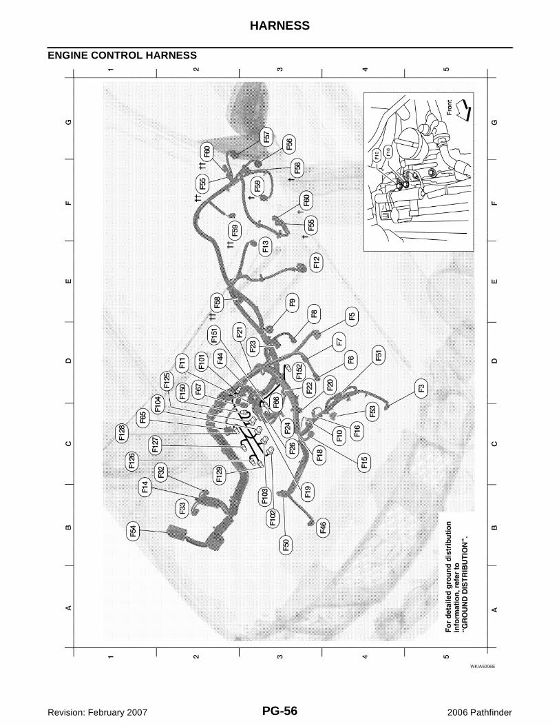
ENGINE CONTROL HARNESS
WKIA5006E
HARNESS
PG-57
C
D
E
F
G
H
I
J
L
M
A
B
PG
Revision: February 2007 2006 Pathfinder
D5 F3 B/1 : A/C Compressor F2 F59†† B/2 : Wait detection switch (all mode 4WD)
E4 F5 B/6 : Air fuel ratio (A/F) sensor 1 (bank 2) G2 F60† GR/2 : 4LO switch (part time 4WD)
D4 F6 GR/3: Ignition coil No. 2 (with power tran- sistor)
C1 F60†† GR/2 : 4LO switch (all-mode 4WD)
D4 F7 GR/3: Ignition coil No. 4 (with power tran- sistor)
F65 B/6 : Air fuel ratio (A/F) sensor 1 (bank 1)
E3 F8 GR/3: Ignition coil No. 6 (with power tran- sistor)
D3 F66 GR/3 : Camshaft position sensor (PHASE) (bank 1)
E3 F9 G/10 : A/T assembly D2 F67 L/4 : To F150
C4 F10 — : Engine ground Injector sub-harness
D2 F11 B/3 : Crankshaft position sensor (POS) D2 F101 GR/4 : To F44
E3 F12 G/4 : Heated oxygen sensor 2 (bank 2) B3 F102 GR/2 : Fuel injector No. 1
E3 F13 L/4 : Heated oxygen sensor 2 (bank 1) B3 F103 GR/2 : Fuel injector No. 3
B1 F14 W/24 : To E5 C1 F104 GR/2 : Fuel injector No. 5
C4 F15 L/2: EVAP canister purge volume control solenoid valve
Ignition coil sub-harness
C4 F16 — : Engine ground D2 F125 G/8 : To F26
C3 F18 GR/2 : Fuel injector No. 2 C1 F126 GR/3 : Ignition coil No. 1 (with power transistor)
B3 F19 B/2 : VIAS control solenoid valve C1 F127 GR/3 : Ignition coil No. 3 (with power transistor)
D4 F20 GR/2 : Fuel injector No. 4 C1 F128 GR/3 : Ignition coil No. 5 (with power transistor)
D2 F21 GR/2 : Condenser-1 C2 F129 G/2: Intake valve timing control solenoid valve (bank 1)
D3 F22 GR/2 : Fuel injector No. 6 Knock sensor sub-harness
D3 F23 B/3: Camshaft position sensor (PHASE) (bank 1)
D2 F150 L/4 : To F67
C3 F24 GR/2 : Engine coolant temperature sensor D2 F151 B/2 : Knock sensor (bank 1)
C3 F26 G/8 : To F125 D3 F152 B/2 : Knock sensor (bank 2)
C2 F32 W/16 : To E2
B2 F33 W/16 : To E19
D2 F44 GR/4 : To F101
B4 F46 B/3 : Power steering pressure sensor
B3 F50 B/6 : Electric throttle control actuator
D4 F51 G/2: Intake valve timing control solenoid valve (bank 2)
C4 F53 B/6 : Mass air flow sensor
B1 F54 B/81 : ECM
F3 F55† B/2 : ATP switch (all-mode 4WD)
F2 F55†† B/2 : ATP switch (part time 4WD)
G3 F56 B/8: Terminal cord assembly (all-mode 4WD)
G3 F57 B/2 : Transfer motor (all-mode 4WD)
F3 F58† B/8: Transfer control device (part time 4WD)
E2 F58†† GR/6: Transfer control device (all-mode 4WD)
F3 F59† GR/2: Wait detection switch (part time 4WD)
PG-58
HARNESS
Revision: February 2007 2006 Pathfinder
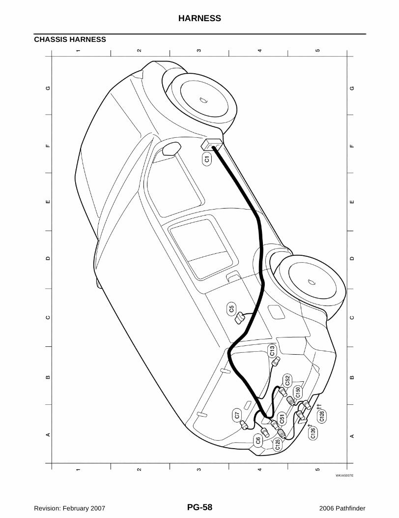
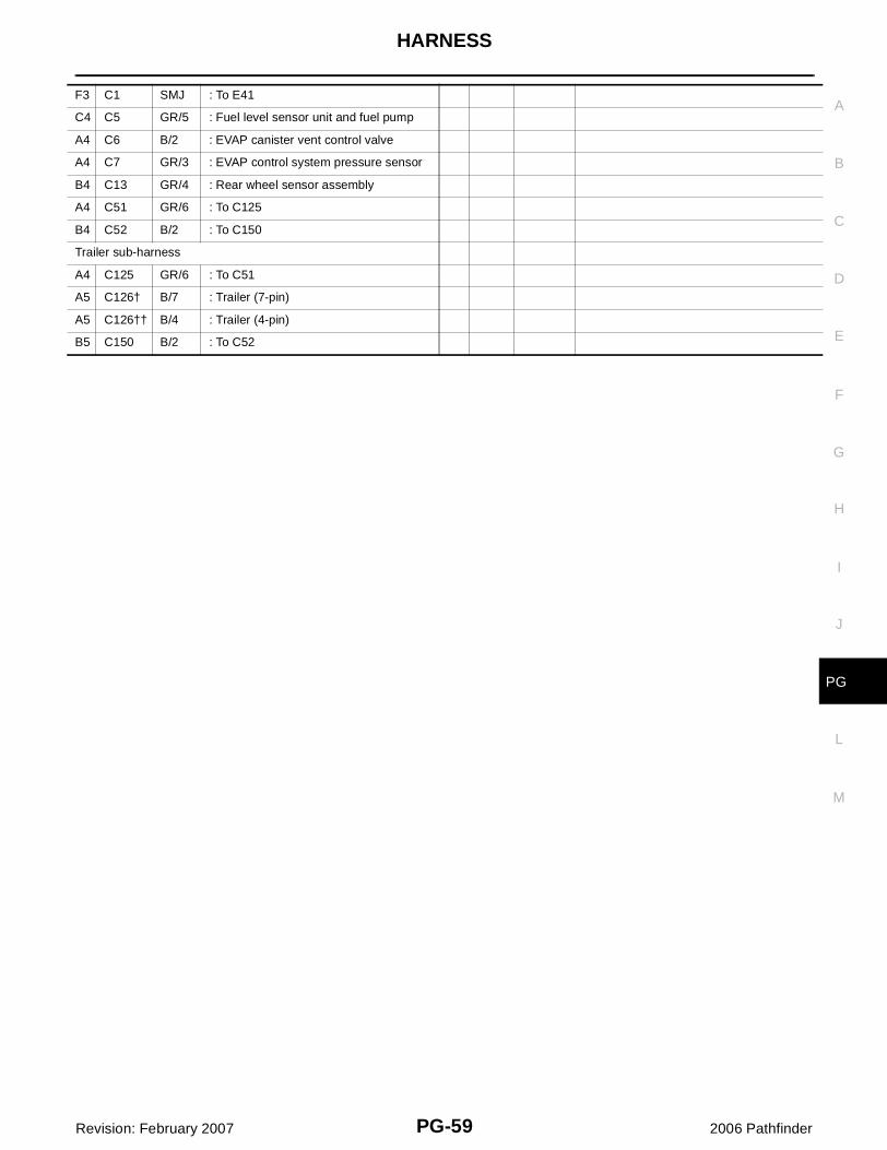
CHASSIS HARNESS
WKIA5007E
HARNESS
PG-59
C
D
E
F
G
H
I
J
L
M
A
B
PG
Revision: February 2007 2006 Pathfinder
F3 C1 SMJ : To E41
C4 C5 GR/5 : Fuel level sensor unit and fuel pump
A4 C6 B/2 : EVAP canister vent control valve
A4 C7 GR/3 : EVAP control system pressure sensor
B4 C13 GR/4 : Rear wheel sensor assembly
A4 C51 GR/6 : To C125
B4 C52 B/2 : To C150
Trailer sub-harness
A4 C125 GR/6 : To C51
A5 C126† B/7 : Trailer (7-pin)
A5 C126†† B/4 : Trailer (4-pin)
B5 C150 B/2 : To C52
PG-60
HARNESS
Revision: February 2007 2006 Pathfinder
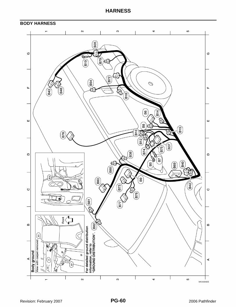
BODY HARNESS
WKIA6060E
HARNESS
PG-61
C
D
E
F
G
H
I
J
L
M
A
B
PG
Revision: February 2007 2006 Pathfinder
D4 B5 —: LH side air bag (satellite sensor) (shield wire)
B2 B82 Y/2 : RH side front curtain air bag module
E4 B6 W/12 : To D201 C3 B83 B/10 : Sunroof motor assembly
D4 B7 — : Body ground
E4 B8 W/3 : Front door switch LH
C4 B9 Y/12 : Air bag diagnosis sensor unit
E4 B10 Y/2 : Front LH side air bag module
D4 B12 W/3 : Seat belt buckle switch LH
E4 B14 Y/2 : Front LH seat belt pre-tensioner
E5 B15 Y/2 : LH side air bag (satellite sensor)
F3 B18 W/3 : Rear door switch LH
G2 B19 — : Body ground
G2 B35 W/6 : Rear combination lamp LH
D5 B37 W/16 : To P1
D3 B38 Y/2 : LH side front curtain air bag module
D5 B40 W/8 : To E34
C5 B42 W/2 : To E36
F1 B43 W/8 : To D401
F1 B48 W/6 : To D402
F2 B54 Y/2 : LH side rear curtain air bag module
D5 B69 SMJ : To M40
F3 B72 W/8 : Subwoofer (with BOSE audio system)
C3 B73 B/6 : Yaw rate/side/decel G sensor
D4 B74 GR/8 : BOSE speaker amp.
D4 B75 B/24 : BOSE speaker amp.
E1 B76 W/16 : Video monitor
C3 B77 W/18 : To M210
C4 B78 Y/2 : To B157
G3 B79 W/4 : Fuel lid lock actuator
D3 B80 W/2 : Vanity lamp LH
C2 B81 W/2 : Vanity lamp RH
PG-62
HARNESS
Revision: February 2007 2006 Pathfinder
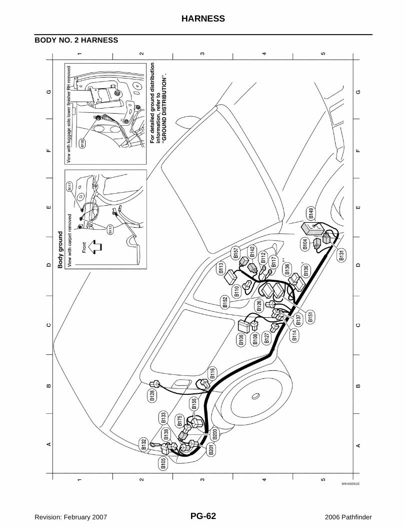
BODY NO. 2 HARNESS
WKIA6061E
HARNESS
PG-63
C
D
E
F
G
H
I
J
L
M
A
B
PG
Revision: February 2007 2006 Pathfinder
D5 B104 W/2 : To E51 A3 B201 B/2 : Rear blower motor
A2 B105 W/6 : Rear combination lamp RH
C4 B106 W/12 : To D301
C4 B108 W/3 : Front door switch RH
D4 B110 W/3 : Seat belt buckle switch RH
D4 B112 —: RH side air bag (satellite sensor) (shield wire)
D3 B113 Y/12 : Air bag diagnosis sensor unit
C5 B114 Y/2 : RH side air bag (satellite sensor)
B3 B116 W/3 : Rear door switch RH
D4 B117 — : Body ground
C4 B126 Y/2 : Front RH side air bag module
C4 B127 Y/2 : Front RH seat belt pre-tensioner
B2 B128 Y/2 : RH side rear curtain air bag module
D5 B131 W/2 : To M162
A2 B132 — : Body ground
A2 B133 W/4 : Rear blower motor resistor
D5 †B136 W/16 : To P151 (with power seat)
D4 ††B136 W/8 : To P151 (without power seat)
C5 B137 B/3 : Belt tension sensor
A2 B138 B/2 : Rear cargo power socket
D4 B142 W/4 : To M83
E5 B149 SMJ : To M36
C5 B151 W/40 : NAVI control unit (with NAVI)
C3 B152 W/32 : NAVI control unit (with NAVI)
B3 B155 B/6 : Air mix door motor (rear)
D4 B157 Y/2 : To B78
A3 B175 W/2 : To B200
Rear blower motor sub-harness
A3 B200 W/2 : To B175
PG-64
HARNESS
Revision: February 2007 2006 Pathfinder
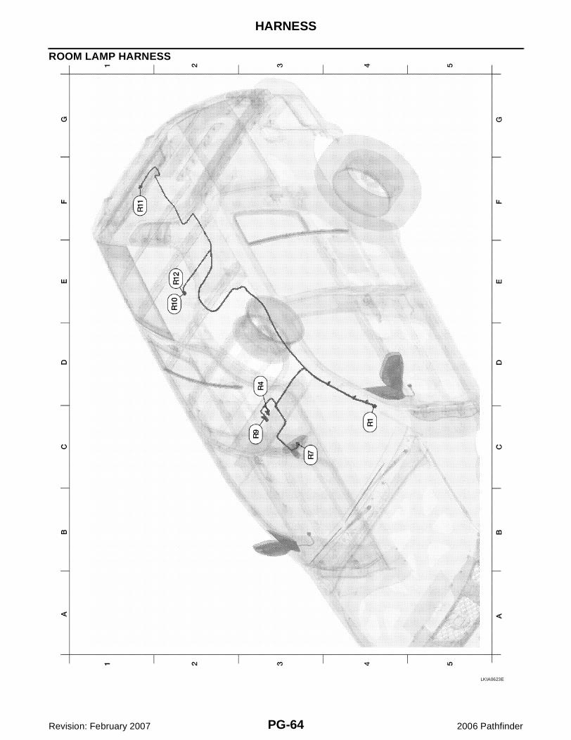
ROOM LAMP HARNESS
LKIA0623E
HARNESS
PG-65
C
D
E
F
G
H
I
J
L
M
A
B
PG
Revision: February 2007 2006 Pathfinder
C4 R1 W/12 : To M1
D3 R4 W/3 : Sunroof switch
C3 R7 W/7: Auto anti-dazzling inside mirror (without HOMELINK® universal transceiver)
C3 R7 B/10: Auto day/night inside mirror (with HOMELINK® universal transceiver)
C3 R9 W/3 : Front room/map lamp assembly
E2 R10 W/3 : Personal lamp 2nd row
F1 R11 W/2 : Cargo lamp
E2 R12 W/3 : Room lamp 2nd row
PG-66
HARNESS
Revision: February 2007 2006 Pathfinder
FRONT DOOR LH HARNESS
FRONT DOOR RH HARNESS
LKIA0624E
LKIA0625E
HARNESS
PG-67
C
D
E
F
G
H
I
J
L
M
A
B
PG
Revision: February 2007 2006 Pathfinder
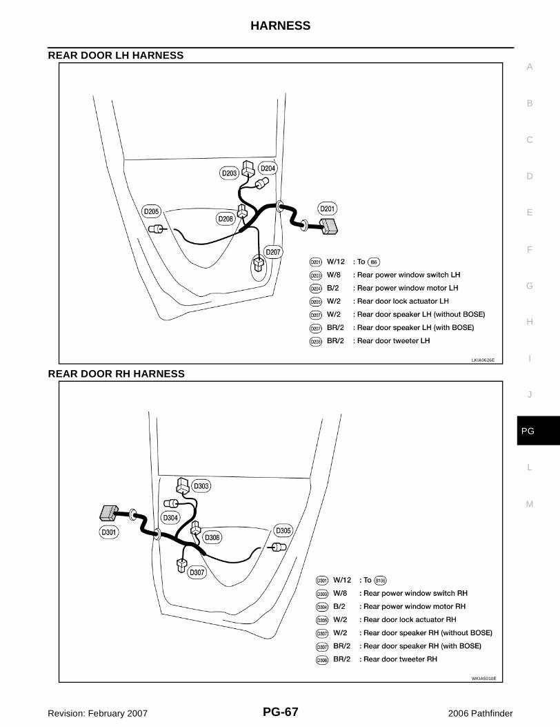
REAR DOOR LH HARNESS
REAR DOOR RH HARNESS
LKIA0626E
WKIA5010E
PG-68
HARNESS
Revision: February 2007 2006 Pathfinder
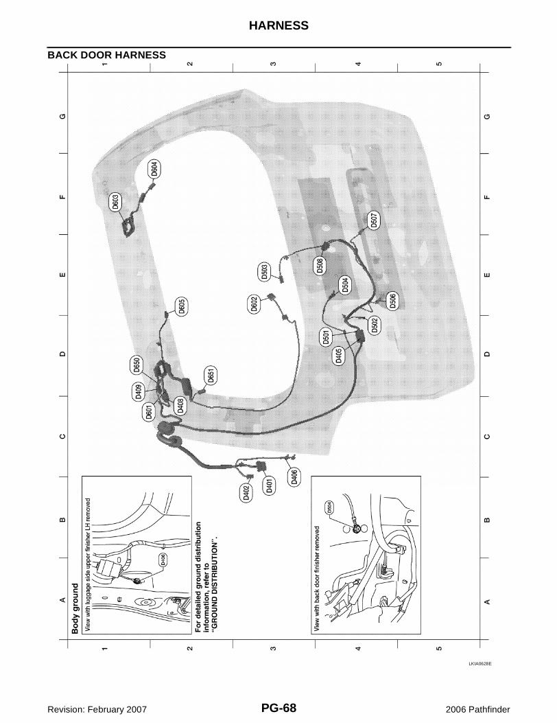
BACK DOOR HARNESS
LKIA0628E
HARNESS
PG-69
C
D
E
F
G
H
I
J
L
M
A
B
PG
Revision: February 2007 2006 Pathfinder
Back door No. 2 harness
B3 D401 W/8 : To B43
B3 D402 W/6 : To B48
D4 D405 W/8 : To D501
B3 D406 — : Body ground
C2 D408 W/4 : To D601
D1 D409 W/1 : To D650
Back door harness
D4 D501 W/8 : To D405
D4 D502 W/3 : Back door switch
E3 D503 B/1 : Glass hatch ajar switch
E4 D504 — : Body ground
E4 D506 W/2 : License plate lamp LH
F4 D507 W/2 : License plate lamp RH
E4 D508 W/4 : Back door lock actuator
Rear window sub-harness
C1 D601 W/4 : To D405
E3 D602 W/4 : Rear wiper motor
F1 D603 — : Body ground (defogger)
F2 D604 B/1 : Rear window defogger
E2 D605 W/2 : High mounted stop lamp
Rear window defogger sub-harness
D1 D650 W/1 : To D409
D2 D651 B/1 : Rear window defogger
PG-70
HARNESS
Revision: February 2007 2006 Pathfinder
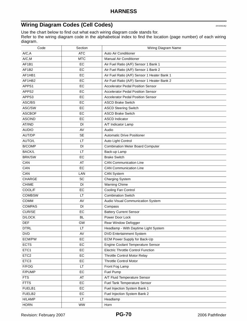
Wiring Diagram Codes (Cell Codes) EKS00G8Q
Use the chart below to find out what each wiring diagram code stands for.Refer to the wiring diagram code in the alphabetical index to find the location (page number) of each wiringdiagram.
Code Section Wiring Diagram Name
A/C,A ATC Auto Air Conditioner
A/C,M MTC Manual Air Conditioner
AF1B1 EC Air Fuel Ratio (A/F) Sensor 1 Bank 1
AF1B2 EC Air Fuel Ratio (A/F) Sensor 1 Bank 2
AF1HB1 EC Air Fuel Ratio (A/F) Sensor 1 Heater Bank 1
AF1HB2 EC Air Fuel Ratio (A/F) Sensor 1 Heater Bank 2
APPS1 EC Accelerator Pedal Position Sensor
APPS2 EC Accelerator Pedal Position Sensor
APPS3 EC Accelerator Pedal Position Sensor
ASC/BS EC ASCD Brake Switch
ASC/SW EC ASCD Steering Switch
ASCBOF EC ASCD Brake Switch
ASCIND EC ASCD Indicator
AT/IND DI A/T Indicator Lamp
AUDIO AV Audio
AUT/DP SE Automatic Drive Positioner
AUTO/L LT Auto Light Control
B/COMP DI Combination Meter Board Computer
BACK/L LT Back-up Lamp
BRK/SW EC Brake Switch
CAN AT CAN Communication Line
CAN EC CAN Communication Line
CAN LAN CAN System
CHARGE SC Charging System
CHIME DI Warning Chime
COOL/F EC Cooling Fan Control
COMBSW LT Combination Switch
COMM AV Audio Visual Communication System
COMPAS DI Compass
CUR/SE EC Battery Current Sensor
D/LOCK BL Power Door Lock
DEF GW Rear Window Defogger
DTRL LT Headlamp - With Daytime Light System
DVD AV DVD Entertainment System
ECM/PW EC ECM Power Supply for Back-Up
ECTS EC Engine Coolant Temperature Sensor
ETC1 EC Electric Throttle Control Function
ETC2 EC Throttle Control Motor Relay
ETC3 EC Throttle Control Motor
F/FOG LT Front Fog Lamp
F/PUMP EC Fuel Pump
FTS AT A/T Fluid Temperature Sensor
FTTS EC Fuel Tank Temperature Sensor
FUELB1 EC Fuel Injection System Bank 1
FUELB2 EC Fuel Injection System Bank 2
H/LAMP LT Headlamp
HORN WW Horn
HARNESS
PG-71
C
D
E
F
G
H
I
J
L
M
A
B
PG
Revision: February 2007 2006 Pathfinder
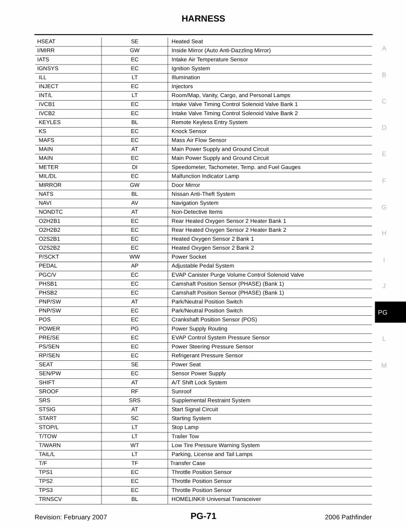
HSEAT SE Heated Seat
I/MIRR GW Inside Mirror (Auto Anti-Dazzling Mirror)
IATS EC Intake Air Temperature Sensor
IGNSYS EC Ignition System
ILL LT Illumination
INJECT EC Injectors
INT/L LT Room/Map, Vanity, Cargo, and Personal Lamps
IVCB1 EC Intake Valve Timing Control Solenoid Valve Bank 1
IVCB2 EC Intake Valve Timing Control Solenoid Valve Bank 2
KEYLES BL Remote Keyless Entry System
KS EC Knock Sensor
MAFS EC Mass Air Flow Sensor
MAIN AT Main Power Supply and Ground Circuit
MAIN EC Main Power Supply and Ground Circuit
METER DI Speedometer, Tachometer, Temp. and Fuel Gauges
MIL/DL EC Malfunction Indicator Lamp
MIRROR GW Door Mirror
NATS BL Nissan Anti-Theft System
NAVI AV Navigation System
NONDTC AT Non-Detective Items
O2H2B1 EC Rear Heated Oxygen Sensor 2 Heater Bank 1
O2H2B2 EC Rear Heated Oxygen Sensor 2 Heater Bank 2
O2S2B1 EC Heated Oxygen Sensor 2 Bank 1
O2S2B2 EC Heated Oxygen Sensor 2 Bank 2
P/SCKT WW Power Socket
PEDAL AP Adjustable Pedal System
PGC/V EC EVAP Canister Purge Volume Control Solenoid Valve
PHSB1 EC Camshaft Position Sensor (PHASE) (Bank 1)
PHSB2 EC Camshaft Position Sensor (PHASE) (Bank 1)
PNP/SW AT Park/Neutral Position Switch
PNP/SW EC Park/Neutral Position Switch
POS EC Crankshaft Position Sensor (POS)
POWER PG Power Supply Routing
PRE/SE EC EVAP Control System Pressure Sensor
PS/SEN EC Power Steering Pressure Sensor
RP/SEN EC Refrigerant Pressure Sensor
SEAT SE Power Seat
SEN/PW EC Sensor Power Supply
SHIFT AT A/T Shift Lock System
SROOF RF Sunroof
SRS SRS Supplemental Restraint System
STSIG AT Start Signal Circuit
START SC Starting System
STOP/L LT Stop Lamp
T/TOW LT Trailer Tow
T/WARN WT Low Tire Pressure Warning System
TAIL/L LT Parking, License and Tail Lamps
T/F TF Transfer Case
TPS1 EC Throttle Position Sensor
TPS2 EC Throttle Position Sensor
TPS3 EC Throttle Position Sensor
TRNSCV BL HOMELINK® Universal Transceiver
PG-72
HARNESS
Revision: February 2007 2006 Pathfinder
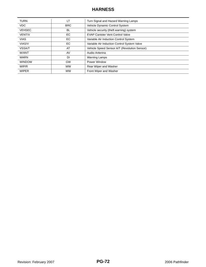
TURN LT Turn Signal and Hazard Warning Lamps
VDC BRC Vehicle Dynamic Control System
VEHSEC BL Vehicle security (theft warning) system
VENT/V EC EVAP Canister Vent Control Valve
VIAS EC Variable Air Induction Control System
VIAS/V EC Variable Air Induction Control System Valve
VSSA/T AT Vehicle Speed Sensor A/T (Revolution Sensor)
W/ANT AV Audio Antenna
WARN DI Warning Lamps
WINDOW GW Power Window
WIP/R WW Rear Wiper and Washer
WIPER WW Front Wiper and Washer
ELECTRICAL UNITS LOCATION
PG-73
C
D
E
F
G
H
I
J
L
M
A
B
PG
Revision: February 2007 2006 Pathfinder
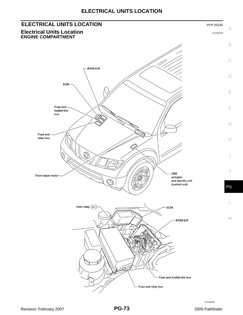
ELECTRICAL UNITS LOCATION PFP:25230
Electrical Units Location EKS00G8R
ENGINE COMPARTMENT
LKIA0629E
PG-74
ELECTRICAL UNITS LOCATION
Revision: February 2007 2006 Pathfinder
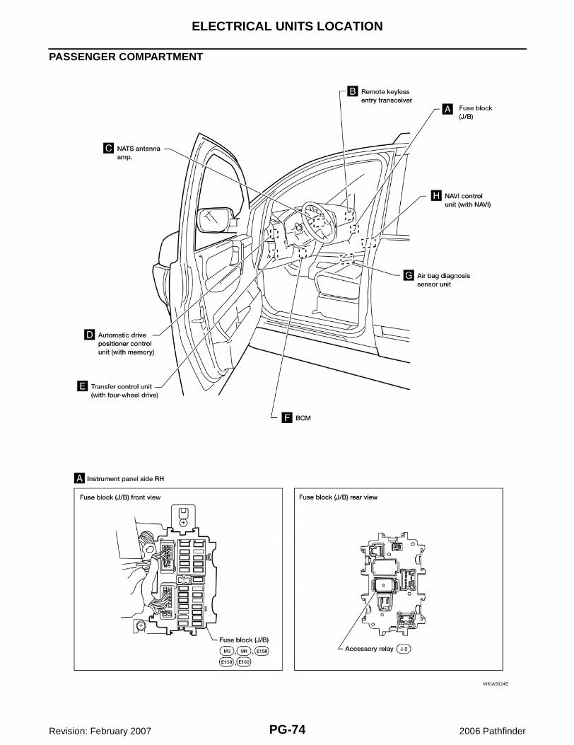
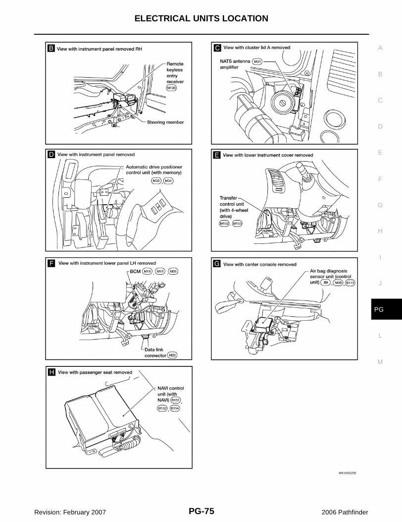
PASSENGER COMPARTMENT
WKIA5024E
ELECTRICAL UNITS LOCATION
PG-75
C
D
E
F
G
H
I
J
L
M
A
B
PG
Revision: February 2007 2006 Pathfinder
WKIA5025E
PG-76
HARNESS CONNECTOR
Revision: February 2007 2006 Pathfinder
HARNESS CONNECTOR PFP:B4341
Description EKS00G8V
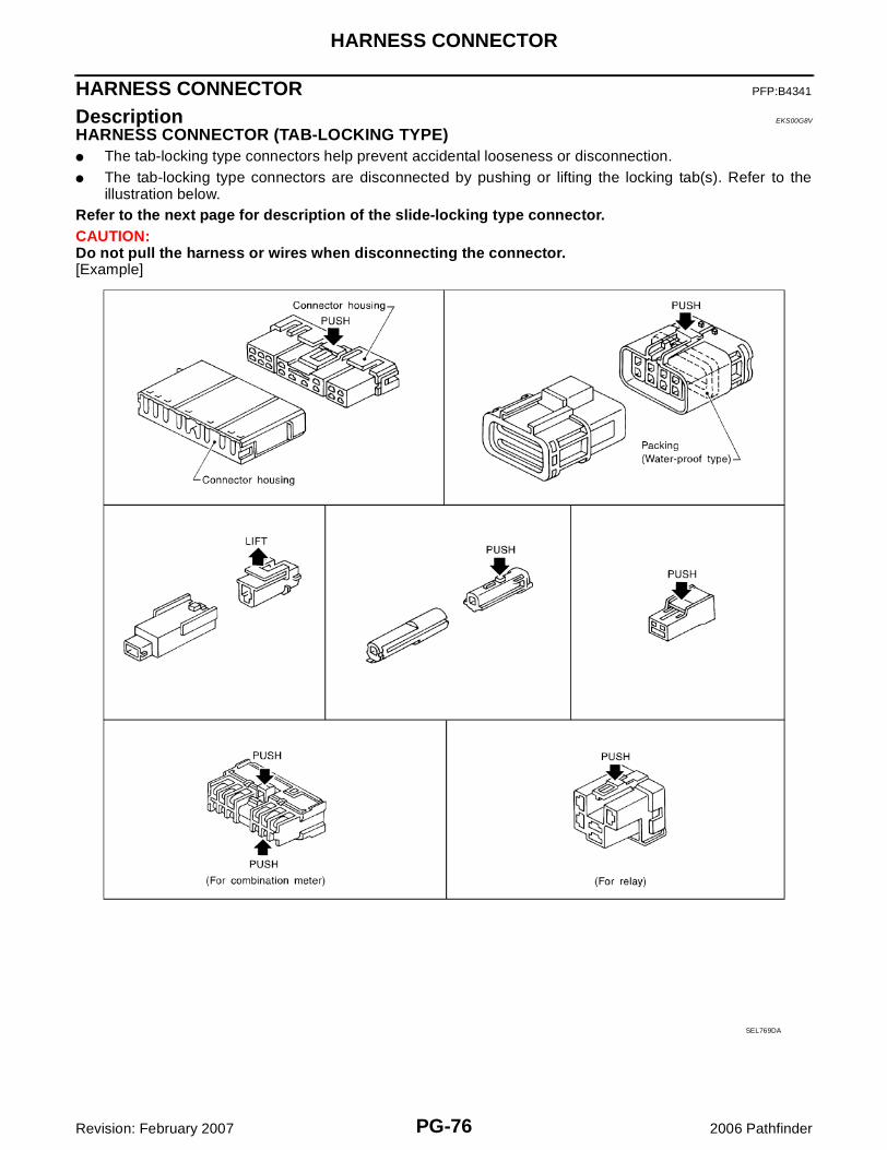
HARNESS CONNECTOR (TAB-LOCKING TYPE)� The tab-locking type connectors help prevent accidental looseness or disconnection.� The tab-locking type connectors are disconnected by pushing or lifting the locking tab(s). Refer to the
illustration below.Refer to the next page for description of the slide-locking type connector.CAUTION:Do not pull the harness or wires when disconnecting the connector.[Example]
SEL769DA
HARNESS CONNECTOR
PG-77
C
D
E
F
G
H
I
J
L
M
A
B
PG
Revision: February 2007 2006 Pathfinder
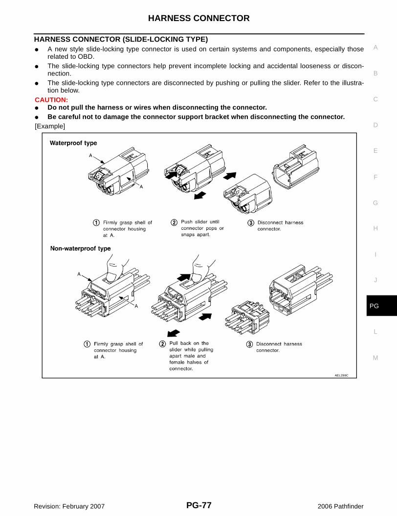
HARNESS CONNECTOR (SLIDE-LOCKING TYPE)� A new style slide-locking type connector is used on certain systems and components, especially those
related to OBD.� The slide-locking type connectors help prevent incomplete locking and accidental looseness or discon-
nection.� The slide-locking type connectors are disconnected by pushing or pulling the slider. Refer to the illustra-
tion below.CAUTION:� Do not pull the harness or wires when disconnecting the connector.� Be careful not to damage the connector support bracket when disconnecting the connector.[Example]
AEL299C
PG-78
HARNESS CONNECTOR
Revision: February 2007 2006 Pathfinder
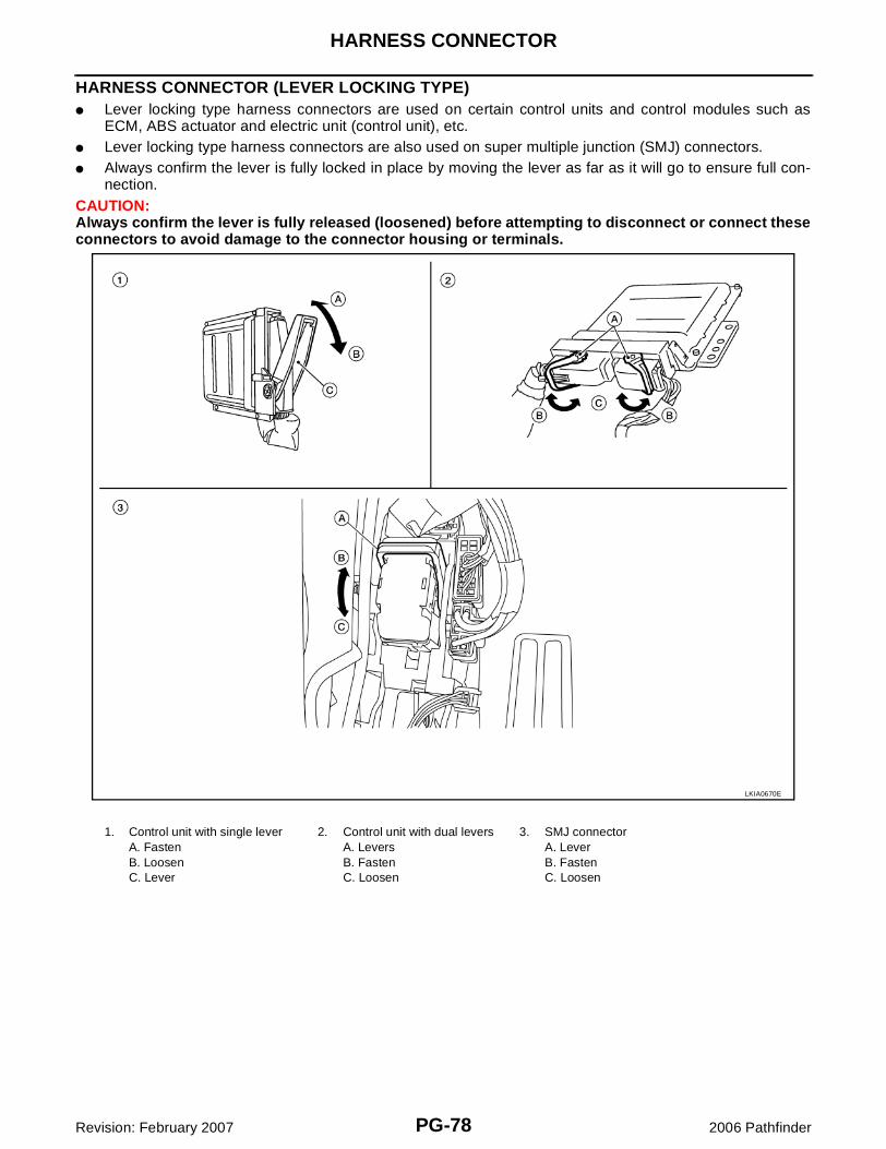
HARNESS CONNECTOR (LEVER LOCKING TYPE)� Lever locking type harness connectors are used on certain control units and control modules such as
ECM, ABS actuator and electric unit (control unit), etc.� Lever locking type harness connectors are also used on super multiple junction (SMJ) connectors.� Always confirm the lever is fully locked in place by moving the lever as far as it will go to ensure full con-
nection.CAUTION:Always confirm the lever is fully released (loosened) before attempting to disconnect or connect theseconnectors to avoid damage to the connector housing or terminals.
LKIA0670E
1. Control unit with single leverA. FastenB. LoosenC. Lever
2. Control unit with dual leversA. LeversB. FastenC. Loosen
3. SMJ connectorA. LeverB. FastenC. Loosen
HARNESS CONNECTOR
PG-79
C
D
E
F
G
H
I
J
L
M
A
B
PG
Revision: February 2007 2006 Pathfinder
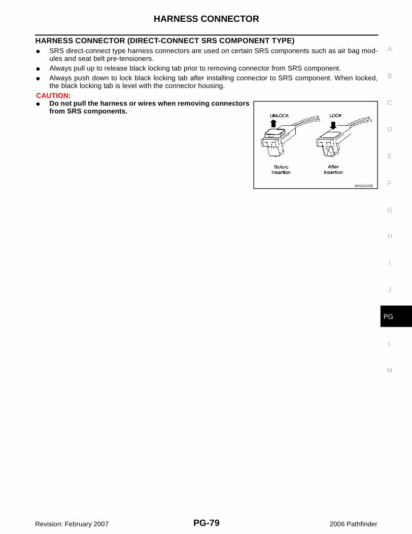
HARNESS CONNECTOR (DIRECT-CONNECT SRS COMPONENT TYPE)� SRS direct-connect type harness connectors are used on certain SRS components such as air bag mod-
ules and seat belt pre-tensioners.� Always pull up to release black locking tab prior to removing connector from SRS component.� Always push down to lock black locking tab after installing connector to SRS component. When locked,
the black locking tab is level with the connector housing.CAUTION:� Do not pull the harness or wires when removing connectors
from SRS components.
WHIA0103E
PG-80
ELECTRICAL UNITS
Revision: February 2007 2006 Pathfinder
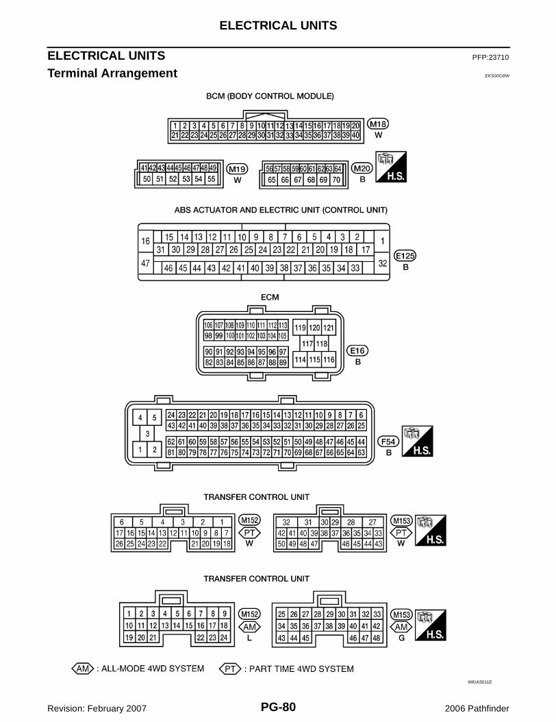
ELECTRICAL UNITS PFP:23710
Terminal Arrangement EKS00G8W
WKIA5011E
STANDARDIZED RELAY
PG-81
C
D
E
F
G
H
I
J
L
M
A
B
PG
Revision: February 2007 2006 Pathfinder
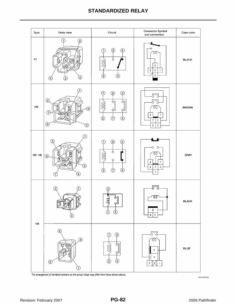
STANDARDIZED RELAY PFP:25230
Description EKS00G8X
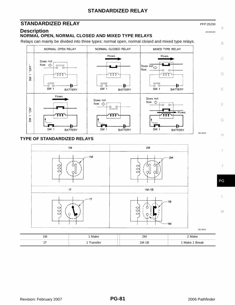
NORMAL OPEN, NORMAL CLOSED AND MIXED TYPE RELAYSRelays can mainly be divided into three types: normal open, normal closed and mixed type relays.
TYPE OF STANDARDIZED RELAYS
SEL881H
SEL882H
1M 1 Make 2M 2 Make
1T 1 Transfer 1M·1B 1 Make 1 Break
PG-82
STANDARDIZED RELAY
Revision: February 2007 2006 Pathfinder
WKIA0253E
SUPER MULTIPLE JUNCTION (SMJ)
PG-83
C
D
E
F
G
H
I
J
L
M
A
B
PG
Revision: February 2007 2006 Pathfinder
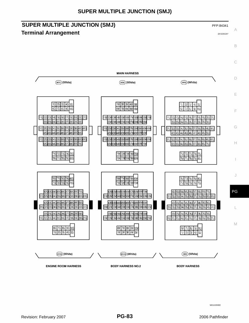
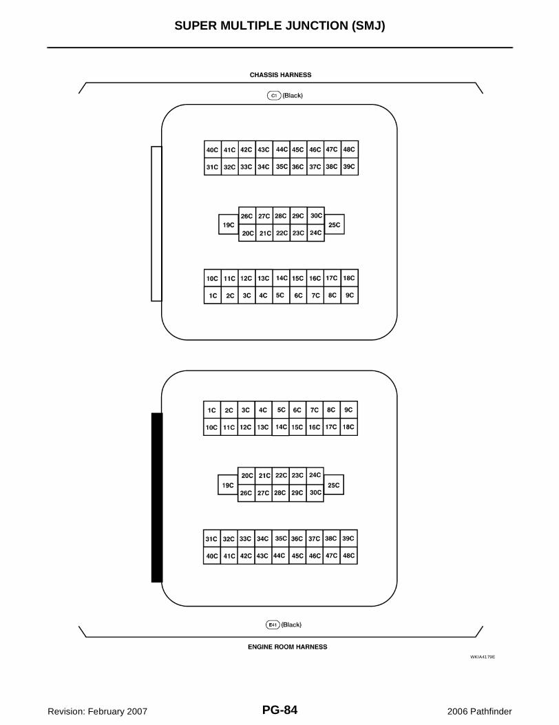
SUPER MULTIPLE JUNCTION (SMJ) PFP:84341
Terminal Arrangement EKS00G8Y
WKIA3590E
PG-84
SUPER MULTIPLE JUNCTION (SMJ)
Revision: February 2007 2006 Pathfinder
WKIA4179E
FUSE BLOCK-JUNCTION BOX (J/B)
PG-85
C
D
E
F
G
H
I
J
L
M
A
B
PG
Revision: February 2007 2006 Pathfinder
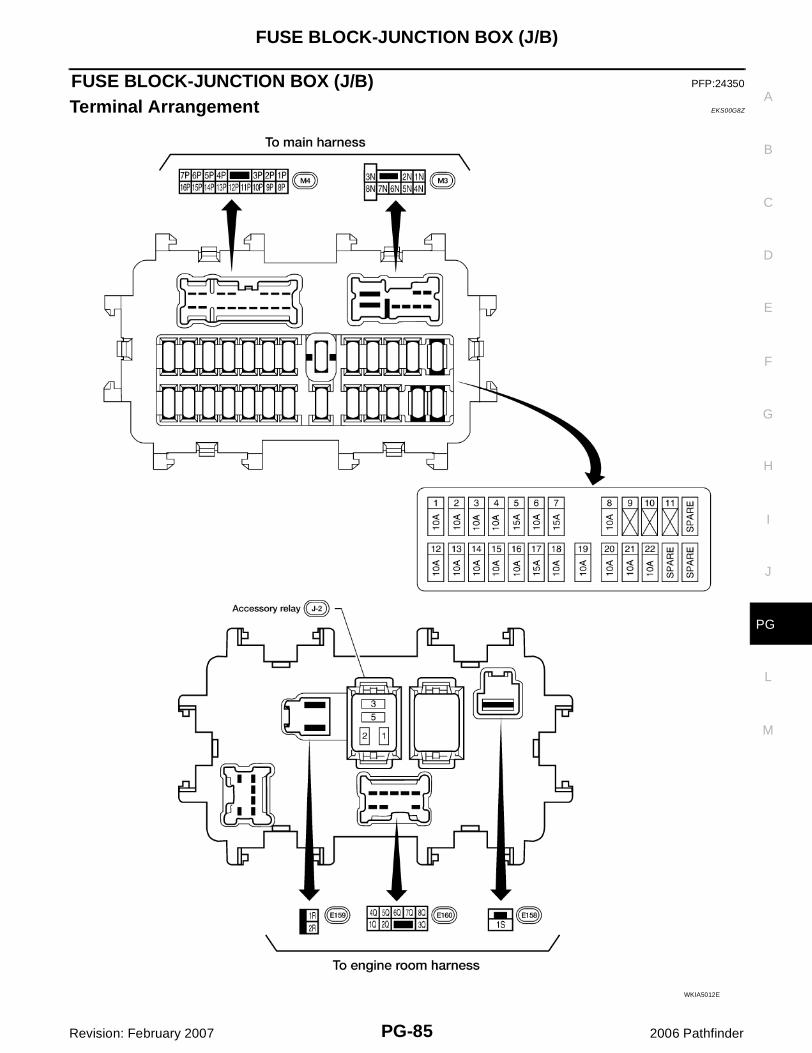
FUSE BLOCK-JUNCTION BOX (J/B) PFP:24350
Terminal Arrangement EKS00G8Z
WKIA5012E
PG-86
FUSE AND FUSIBLE LINK BOX
Revision: February 2007 2006 Pathfinder
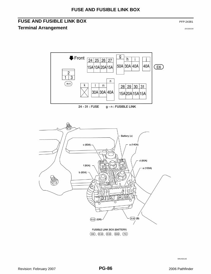
FUSE AND FUSIBLE LINK BOX PFP:24381
Terminal Arrangement EKS00G90
WKIA5013E
FUSE AND RELAY BOX
PG-87
C
D
E
F
G
H
I
J
L
M
A
B
PG
Revision: February 2007 2006 Pathfinder
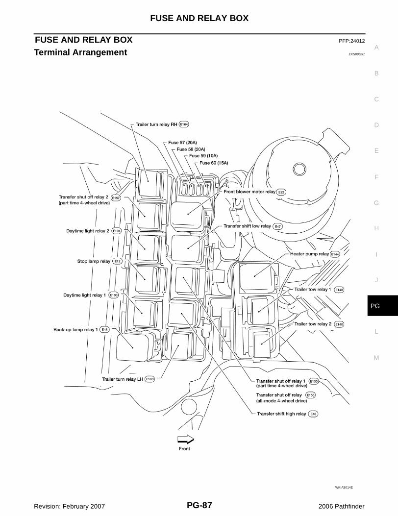
FUSE AND RELAY BOX PFP:24012
Terminal Arrangement EKS00G91
WKIA5014E

PG-88
FUSE AND RELAY BOX
Revision: February 2007 2006 Pathfinder


![The Trove [multi]/1st... · PATHFINDER RPG CORE RULEBOOK , PATHFINDER RPG BESTI ARY , PATHFINDER RPG BESTIARY 2 , PATHFINDER RPG BESTIARY 3 , PATHFINDER RPG ADVANCED PLAYER S GUID](https://img.pdfslide.us/doc/110x75/60c7beb87d66ea6048574996/the-trove-multi1st-pathfinder-rpg-core-rulebook-pathfinder-rpg-besti-ary.jpg)