Embed Size (px)
Citation preview

Wireless Sensor Networks
JYOTHISHMATHI INSTITUTE OF TECHNOLOGY & SCIENCE
G.ANIL KUMAR
ASST. PROFESSOR

2
Single node architecture: hardware and software
components of a sensor node - WSN Network
architecture: typical network architectures-data relaying
and aggregation strategies -MAC layer protocols: self-
organizing, Hybrid TDMA/FDMA and CSMA based
MAC- IEEE 802.15.4.
WIRELESS SENSOR NETWORKS
(WSNS) AND MAC PROTOCOLS
Introduction
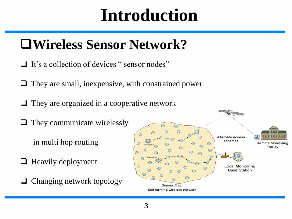
❑Wireless Sensor Network?
❑ It’s a collection of devices “ sensor nodes”
❑ They are small, inexpensive, with constrained power
❑ They are organized in a cooperative network
❑ They communicate wirelessly
in multi hop routing
❑ Heavily deployment
❑ Changing network topology
3

Introduction
❑Component and Schematic of Node
❑ Processor.
❑Memory.
❑ RF Radio.
❑ Power Source.
❑ Sensor.
❑ GPS
Control
SignalProcessor
SensorsWireless Transmit
ter/ Receiver
Processing And
Decision Making
Power
4

Introduction
❑Goal of Wireless Sensor Network
❑ Collect data at regular intervals.
❑ Then transform data into an electrical signal.
❑ Finally, send the signals to the sink or the base nod.
❑Types of Wireless Sensor Network
❑ Temperature sensor.
❑ Light sensor.
❑ Sound sensor.
❑ Vibration Sensor.
5

Introduction
❑Communication pattern
❑ Broadcast : Base station transmits message to all its immediate
neighbors.
❑ Converge cast : a group of sensors communicates to a specific
sensor
❑ Local gossip: a sensor node sends a message to its neighboring
nodes within a range.
6

7
WSN Definition❑A sensor network is composed of a large number of sensor nodes
that are densely deployed inside or very close to the phenomenon
❑random deployment
❑self-organizing capabilities
❑Each node of the sensor networks consist of three subsystem:
❑Sensor subsystem: senses the environment
❑Processing subsystem: performs local computations on the sensed
data
❑Communication subsystem: responsible for message exchange
with neighboring sensor nodes
❑The features of sensor nodes
❑Limited sensing region, processing power, energy

❑The advantage of sensor networks
❑Robust : a large number of sensors
❑Reliable :
❑Accurate : sensor networks covering a wider region
❑Fault-tolerant : many nodes are sensing the same event
❑Two important operations in a sensor networks
❑Data dissemination : the propagation of data/queries throughout
the network
❑Data gathering : the collection of observed data from the
individual sensor nodes to a sink
❑The different types of sensors
❑Seismic, thermal, visual, infrared
WSN
8

9
WSN Communication Architecture

10
Components of Sensor Node

11
Protocol Stack
❑Protocols should be
❑Power aware
❑Location aware
❑Application aware

12
WSN Characteristics
❑Major differences between sensor and ad-hoc network
❑Number of nodes is higher
❑Densely deployment
❑Sensor nodes are prone to failure.
❑Frequent topology changes
❑Broadcast communication paradigm
❑Limited processing and power capabilities.
❑Possible absence of unique global ID
13
WSN Design Factors
❑Fault Tolerance
❑Scalability
❑Production Costs
❑Hardware Constraints
❑Sensor Network Topology
❑Environment
❑Transmission Media
❑Power Consumption

14
Design Factors : Fault Tolerance
❑Each Nodes are prone to unexpected
failure (more than other network)
❑Fault tolerance is the ability to sustain
sensor network functionalities without
any interruption due to sensor node
failures.
15
Design Factors : Scalability
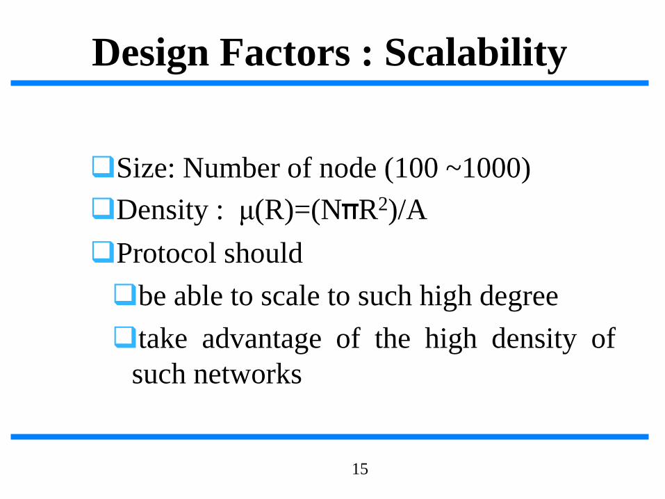
❑Size: Number of node (100 ~1000)
❑Density : μ(R)=(N R2)/A
❑Protocol should
❑be able to scale to such high degree
❑take advantage of the high density of
such networks

16
Design Factors: Production Costs
❑The cost of a single node must be lowgiven the amount of functionalities
❑Much less than $1

17
Design Factors:Hardware Constraint
❑All these units combined together must
❑Extremely low power
❑Extremely small volume

18
Design Factors : Topology
❑Must be maintained specially in very high
densities
❑Pre-deployment and deployment phase
❑Post-deployment phase
❑Re-deployment of additional nodes phase

19
Design Factors : Environment
❑May be inaccessible
❑either because of hostile environment
❑or because they are embedded in a structure
❑Impact of environment condition
❑Temperature
❑Humidity
❑Movement
❑Underwater
❑Underground

20
Design Factors: Environment
❑Busy intersections
❑Interior of a large machinery
❑Bottom of an ocean
❑Surface of an ocean during a tornado
❑Biologically or chemically contaminated field
❑Battlefield beyond the enemy lines
❑Home or a large building
❑Large warehouse
❑Animals
❑Fast moving vehicles
❑Drain or river moving with current

21
Design Factors : Transmission Media
❑RF
❑Infrared
❑Optical
❑Acoustic

22
Design Factors: Power Consumption
❑Power conservation
❑Sensing
❑Communication
❑Data processing

Applications of WSN
❑ Global scale
❑ Battle field
❑ Factories
❑ Buildings
❑ Homes
❑ bodies
23

Applications of Sensor Networks
❑Using in military
❑Battlefield surveillance and monitoring, guidance systems of
intelligent missiles, detection of attack by weapons of mass
destruction such as chemical, biological, or nuclear
❑Using in nature
❑ Forest fire, flood detection, habitat exploration of animals
❑Using in health
❑Monitor the patient’s heart rate or blood pressure, and sent regularly
to alert the concerned doctor, provide patients a greater freedom of
movement
24

❑Using in home (smart home)❑ Sensor node can built into appliances at home, such as ovens,
refrigerators, and vacuum cleaners, which enable them to interactwith each other and be remote-controlled
❑Using in office building❑Airflow and temperature of different parts of the building can be
automatically controlled
❑Using in warehouse❑ Improve their inventory control system by installing sensors on
the products to track their movement
25
Applications of Sensor Networks

Comparison with Ad Hoc Wireless
Networks
❑Different from Ad Hoc wireless networks
❑The number of nodes in sensor network can be several orders of magnitudelarge than the number of nodes in an ad hoc network.
❑ Sensor nodes are more easy to failure and energy drain, and their batterysources are usually not replaceable or rechargeable.
❑ Sensor nodes may not have unique global identifiers (ID), so uniqueaddressing is not always feasible in sensor networks.
❑ Sensor networks are data-centric, the queries in sensor networks areaddressed to nodes which have data satisfying some conditions. Ad Hocnetworks are address-centric, with queries addressed to particular nodesspecified by their unique address.
❑Data fusion/aggregation: the sensor nodes aggregate the local informationbefore relaying. The goals are reduce bandwidth consumption, mediaaccess delay, and power consumption for communication.
26

Issues and Challenges
❑ Sensor nodes are randomly deployed and hence do not fit into any regular topology.Once deployed, they usually do not require any human intervention. Hence, thesetup and maintenance of the network should be entirely autonomous.
❑ Sensor networks are infrastructure-less. Therefore, all routing and maintenancealgorithms need to be distributed.
❑ Energy problem
❑ Hardware and software should be designed to conserve power
❑ Sensor nodes should be able to synchronize with each other in a completelydistributed manner, so that TDMA schedules can be imposed.
❑ A sensor network should also be capable of adapting to changing connectivity due tothe failure of nodes, or new nodes powering up. The routing protocols should beable to dynamically include or avoid sensor nodes in their paths.
❑ Real-time communication over sensor networks must be supported through
provision of guarantees on maximum delay, minimum bandwidth, or other QoS
parameters.
❑ Provision must be made for secure communication over sensor networks, especially
for military applications which carry sensitive data.
27

Classification of sensor network
protocol
28
Sensor Network Architecture
❑The two basic kinds of sensor network
architecture
❑Layered Architecture
❑Clustered Architecture
29

Layered Architecture
❑A layered architecture has a single
powerful base station, and the layers of
sensor nodes around it correspond to
the nodes that have the same hop-count
to the BS.
❑ In the in-building scenario, the BS acts
an access point to a wired network, and
small nodes form a wireless backbone
to provide wireless connectivity.
❑The advantage of a layered architecture
is that each node is involved only in
short-distance, low-power
transmissions to nodes of the
neighboring layers.
30

Unified Network Protocol
Framework (UNPF)
❑UNPF is a set of protocols for complete
implementation of a layered architecture for
sensor networks
❑UNPF integrates three operations in its
protocol structure:
❑Network initialization and maintenance
❑MAC protocol
❑Routing protocol
31

Network initialization and
maintenance❑The BS broadcasts its ID using a known CDMA code on the
common control channel.
❑All node which hear this broadcast then record the BS ID. They
send a beacon signal with their own IDs at their low default
power levels.
❑Those nodes which the BS can hear form layer one
❑BS broadcasts a control packet with all layer one node IDs. All
nodes send a beacon signal again.
❑The layer one nodes record the IDs which they hear (form layer
two) and inform the BS of the layer two nodes IDs.
❑Periodic beaconing updates neighbor information and change
the layer structure if nodes die out or move out of range.
32

MAC protocol
❑During the data transmission phase, the distributed TDMA
receiver oriented channel (DTROC) assignment MAC protocol is
used.
❑Two steps of DTROC
❑Channel allocation : Each node is assigned a reception channel
by the BS, and channel reuse is such that collisions are avoided.
❑Channel scheduling : The node schedules transmission slots for
all its neighbors and broadcasts the schedule. This enables
collision-free transmission and saves energy, as nodes can turn
off when they are not involved on a send/receive operation.
33
Routing protocol
❑Downlink from the BS is by direct broadcast on the
control channel. Uplink from the sensor nodes to BS is
by multi-hop data forwarding.
❑The node to which a packet is to be forwarded is
selected considering the remaining energy of the nodes.
This achieves a higher network lifetime.
34

UNPF-R
❑Optimize the network performance by make the sensor nodes adaptively vary
their transmission range.
❑Because while a very small transmission range cause network partitioning, a very
large transmission range reduce the spatial reuse of frequencies.
❑The optimal range (R) is determined by simulated annealing
❑ Objective function :
❑ N : the total number of sensors
❑ n : the number of nodes in layer one
❑ : the energy consumption per packet
❑ d : the average packet delay
35

UNPF-R
❑If no packet is received by the BS from any sensor node for
some interval of time, the transmission range increase by .
Otherwise, the transmission range is either decrease by with
probability 0.5 x ( n / N ), or increase by with
probability [ 1 – 0.5 x ( n / N ) ].
❑If , then the transmission range R’ is adopt.
Otherwise, R is modified to R’ with probability
❑T : the temperature parameter
❑The advantage of the UNPF-R :
❑Minimize the energy x delay
❑Maximize the number of nodes which can connect to the BS
36

Clustered Architecture❑A clustered architecture organizes the
sensor nodes into clusters, each governed
by a cluster-head. The nodes in each
cluster are involved in message exchanges
with their cluster-heads, and these heads
send message to a BS.
❑Clustered architecture is useful for sensor
networks because of its inherent suitability
for data fusion. The data gathered by all
member of the cluster can be fused at the
cluster-head, and only the resulting
information needs to be communicated to
the BS.
❑The cluster formation and election of
cluster-heads must be an autonomous,
distributed process.
37

Low-Energy Adaptive Clustering
Hierarchy (LEACH)
❑LEACH is a clustering-based protocol that minimizes energy
dissipation in sensor networks. The operation of LEACH is spilt
into two phases : setup and steady.
❑ Setup phase : each sensor node chooses a random number between 0 and 1. If
this is lower than the threshold for node n, T(n), the sensor node becomes a
cluster-head. The threshold T(n) is calculated as
❑P : the percentage of nodes which are cluster-heads
❑ r : the current round
❑G : the set of nodes that has not been cluster-heads in the past 1/P rounds
38

❑After selection, the cluster-heads advertise their selection to
all nodes. All nodes choose their nearest cluster-head by
signal strength (RSSI). The cluster-heads then assign a
TDMA schedule for their cluster members
❑Steady phase : data transmission takes place based on the
TDMA schedule, and the cluster-heads perform data
aggregation/fusion.
❑After a certain period of time in the steady phase, cluster-
heads are selected again through the setup phase.
39
Low-Energy Adaptive Clustering
Hierarchy (LEACH)

Data Dissemination
❑Data dissemination is the process by which queries or data are
routed in the sensor network. The data collected by sensor nodes
has to be communicated to the node which interested in the data.
❑The node that generates data is call source and the information to
be reported is called an event. A node which interested in an event
is called sink.
❑Data dissemination consist of a two-step process : interest
propagation and data propagation.
❑ Interest propagation : for every event that a sink is interested in, it broadcasts
its interest to is neighbor, and across the network.
❑Data dissemination : When an event is detected, it reported to the interested
nodes (sink).
40

Flooding
❑Each node which receives a packet (queries/data) broadcasts it if the
maximum hop-count of the packet is not reached and the node itself
is not the destination of the packet.
❑Disadvantages :
❑Implosion : this is the situation when duplicate messages are send
to the same node. This occurs when a node receives copies of the
same messages from many of its neighbors.
❑Overlap : the same event may be sensed by more than one node
due to overlapping regions of coverage. This results in their
neighbors receiving duplicate reports of the same event.
❑Resource blindness : the flooding protocol does not consider the
available energy at the nodes and results in many redundant
transmissions. Hence, it reduces the network lifetime.
41

Gossiping
❑Modified version of flooding
❑The nodes do not broadcast a packet, but send
it to a randomly selected neighbor.
❑Avoid the problem of implosion
❑It takes a long time for message to propagate
throughout the network.
❑It does not guarantee that all nodes of network
will receive the message.
42
Rumor Routing
❑Agent-based path creation algorithm
❑Agent is a long-lived packet created at random
by nodes, and it will die after visit k hops.
❑It circulated in the network to establish shortest
paths to events that they encounter.
❑When an agent finds a node whose path to an
event is longer than its own, it updates the
node’s routing table.
43

Rumor routing
44
After selection, the cluster-heads advertise their selection to all nodes. All nodes choose their
nearest cluster-head by signal strength (RSSI). The cluster-heads then assign a TDMA
schedule for their cluster members

Sequential Assignment Routing (SAR)
❑The sequential assignment routing (SAR) algorithm creates
multiple trees, where the root of each tree is a one-hop neighbor
of the sink.
❑To avoid nodes with low throughput or high delay.
❑Each sensor node records two parameters about each path though
it : available energy resources on the path and an additive QoS
metric such as delay.
❑Higher priority packets take lower delay paths, and lower priority packets
have to use the paths of greater delay, so that the priority x delay QoS
metric is maintained.
❑SAR minimizes the average weighted QoS metric over the
lifetime of the network.
45

46
Sequential Assignment Routing (SAR)

Directed Diffusion
❑The directed diffusion protocol is useful in scenarios where the sensor
nodes themselves generate requests/queries for data sensed by other
nodes.
❑Each sensor node names its data with one or more attributes.
❑Each sensor node express their interest depending on these attributes.
❑Each path is associated with a interest gradient, while positive gradient
make the data flow along the path, negative gradient inhibit the
distribution data along a particular path.
❑Example : two path formed with gradient 0.4 and 0.8, the source may
twice as much data along the higher one
❑Suppose the sink wants more frequent update from the sensor which
have detected an event => send a higher data-rate requirement for
increasing the gradient of that path.
47
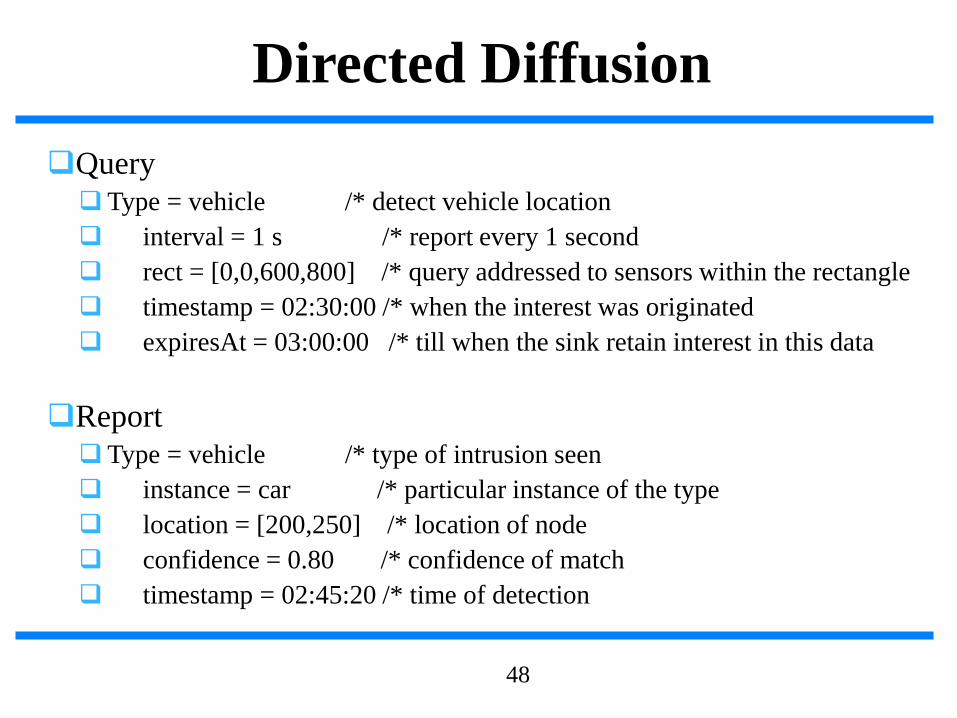
❑Query
❑Type = vehicle /* detect vehicle location
❑ interval = 1 s /* report every 1 second
❑ rect = [0,0,600,800] /* query addressed to sensors within the rectangle
❑ timestamp = 02:30:00 /* when the interest was originated
❑ expiresAt = 03:00:00 /* till when the sink retain interest in this data
❑Report
❑Type = vehicle /* type of intrusion seen
❑ instance = car /* particular instance of the type
❑ location = [200,250] /* location of node
❑ confidence = 0.80 /* confidence of match
❑ timestamp = 02:45:20 /* time of detection
48
Directed Diffusion

Sensor Protocols for Information via
Negotiation ❑ SPIN use negotiation and resource
adaptation to address the disadvantage
of flooding.
❑Reduce overlap and implosion, and
prolong network lifetime.
❑Use meta-data instead of raw data.
❑ SPIN has three types of
messages:ADV, REQ, and DATA.
❑ SPIN-2 using an energy threshold to
reduce participation. A node may join
in the ADV-REQ-DATA handshake
only if it has sufficient resource above
a threshold.
49

Cost-Field Approach
❑The cost-field approach considers the problem of setting up paths to
a sink. The first phase being to set up the cost field, based on metrics
such as delay. The second phase being data dissemination using the
costs.
❑A sink broadcasts an ADV packet with its own cost as 0.
❑When a node N hears an ADV message from node M, it sets its own
path cost to min (LN,LM+CNM), where LN is the total path cost from
node N to the sink, LM is the cost of node M to the sink, CNM is the
cost from N to M.
❑If LN updated, the new cost is broadcast though another ADV.
❑The back-off time make a node defer its ADV instead of immediately
broadcast it. The back-off time is r x CMN, where r is a parameter of
algorithm.
50

51
Cost-Field Approach

Geographic Hash Table (GHT)
❑GHT hashes keys into geographic
coordinates and stores a (key, value)
pair at the sensor node nearest to the
hash value.
❑Stored data is replicated to ensure
redundancy in case of node failures.
52
❑The data is distributed among nodes such that it is scalable and
the storage load is balanced.
❑The routing protocol used is greedy perimeter stateless routing
(GPSR), which again uses geographic information to route the
data and queries.

Small Minimum Energy
Communication Network
❑If the entire sensor network is represented by G, the subgraph G’ is
constructed such that the energy usage of the network is minimized.
❑The number of edges in G’ is less than G, and the connectivity
between any two nodes is not disrupted by G’.
❑The power required to transmit data between u and v is modeled as
❑ t : constant
❑ n : loss exponent indicating the loss of power with distance from
transmitter
❑ d(u,v) : the distance between u and v
❑It would be more economical to transmit data by smaller hops
53

❑Suppose the path between u (i.e. u0) and v (i.e. uk) is represented
by r = (u0, u1, … uk), each (ui, ui+1) is edge in G’
❑The total power consumed for the transmission is
❑C : the power needed to receive the data
❑The path r is the minimum energy path if C(r) ≦ C(r’) for all
path’s r’ between u and v in G.
❑SMECN uses only the ME paths from G’ for data transmission, so
that the overall energy consumed is minimized.
54
Small Minimum Energy
Communication Network

Data Gathering
❑The objective of the data gathering problem is to
transmit the sensed data from each sensor node to a BS.
❑The goal of algorithm which implement data gathering
is
❑maximize the lifetime of network
❑Minimum energy should be consumed
❑The transmission occur with minimum delay
❑The energy x delay metric is used to compare
algorithm
55

Direct Transmission
❑All sensor nodes transmit their data directly to
the BS.
❑It cost expensive when the sensor nodes are
very far from the BS.
❑Nodes must take turns while transmitting to the
BS to avoid collision, so the media access delay
is also large. Hence, this scheme performs
poorly with respect to the energy x delay metric.
56

Power-Efficient Gathering for
Sensor Information Systems
❑ PEGASIS based on the assumption that all sensor nodes know the location of
every other node.
❑Any node has the required transmission range to reach the BS in one hop,
when it is selected as a leader.
❑The goal of PEGASIS are as following
❑ Minimize the distance over which each node transmit
❑ Minimize the broadcasting overhead
❑ Minimize the number of messages that need to be sent to the BS
❑ Distribute the energy consumption equally across all nodes
❑To construct a chain of sensor nodes, starting from the node farthest from the
BS. At each step, the nearest neighbor which has not been visited is added to
the chain.
❑ It is reconstructed when nodes die out.
57
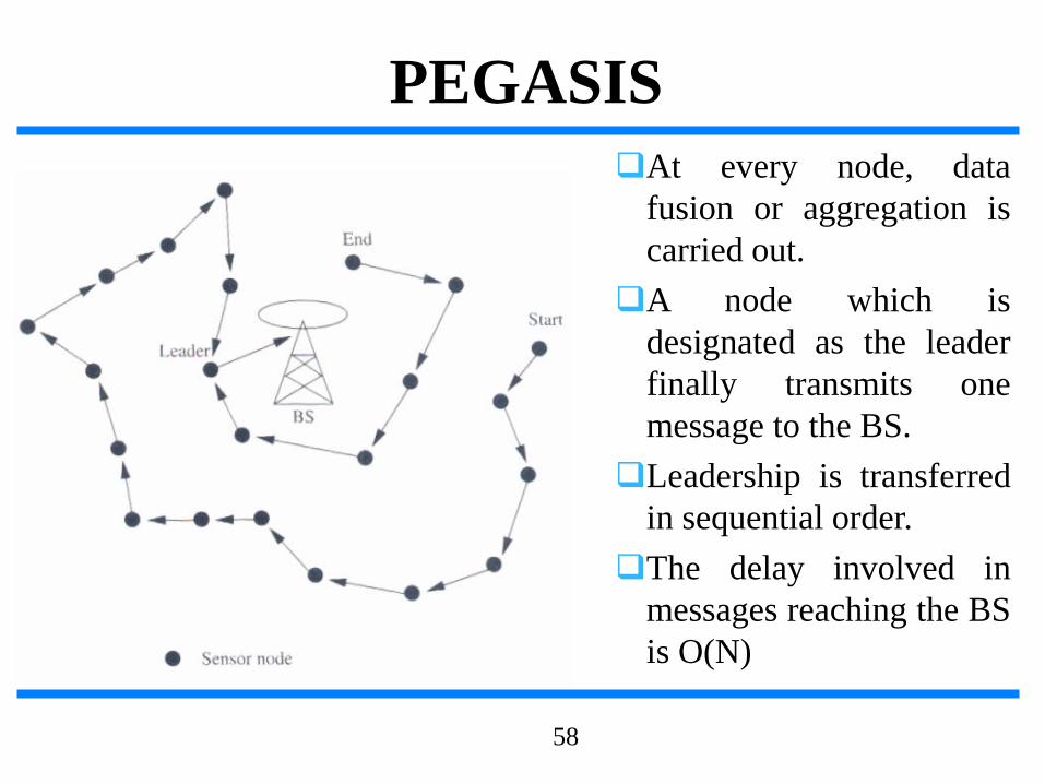
❑At every node, data
fusion or aggregation is
carried out.
❑A node which is
designated as the leader
finally transmits one
message to the BS.
❑Leadership is transferred
in sequential order.
❑The delay involved in
messages reaching the BS
is O(N)
58
PEGASIS

Binary Scheme
❑This is a chain-based scheme like PEGASIS, which classifies
nodes into different levels.
❑This scheme is possible when nodes communicate using CDMA,
so that transmissions of each level can take place simultaneously.
❑The delay is O(logN)
59

Chain-Based Three-Level Scheme
❑For non-CDMA sensor nodes
❑The chain is divided into a number of groups to space
out simultaneous transmissions in order to minimize
interference.
❑Within a group, nodes transmit data to the group leader,
and the leader fusion the data, and become the member
to the next level.
❑In the second level, all nodes are divided into two groups.
❑In the third level, consists of a message exchange
between one node from each group of the second level.
❑Finally, the leader transmit a single message to the BS.
60

61
Chain-Based Three-Level Scheme
MAC Protocols for Sensor Networks
❑The challenges posed by sensor network MAC protocol
❑No single controlling authority, so global synchronization is
difficult
❑Power efficiency issue
❑Frequent topology changes due to mobility and failure
❑There are three kinds of MAC protocols used in sensor
network:
❑Fixed-allocation
❑Demand-based
❑Contention-based
62

❑Fixed-allocation MAC protocol
❑Share the common medium through a predetermined
assignment.
❑It is suitable for sensor network that continuously monitor
and generate deterministic data traffic
❑Provide a bounded delay for each node
❑However, in the case of bursty traffic, where the channel
requirements of each node may vary over time, it may lead to
inefficient usage of the channel.
63
MAC Protocols for Sensor Networks

❑ Demand-based MAC protocol
❑ Used in such cases, where the channel is allocated accordingto the demand of the node
❑ Variable rate traffic can be efficiently transmitted
❑ Require the additional overhead of a reservation process
❑ Contention-based MAC protocol
❑ Random-access-based contention for the channel whenpackets need to be transmitted
❑ Suitable for bursty traffic
❑ Collisions and no delay guarantees, are not suitable fordelay-sensitive or real-time traffic
64
MAC Protocols for Sensor Networks

Self-Organizing MAC for Sensor
Networks and Eavesdrop and Register
❑Self-Organizing MAC for sensor (SMACS) networks and eavesdrop
and register (EAR) are two protocols which handle network
initialization and mobility support, respectively.
❑In SMACS
❑neighbor discovery and channel assignment take place
simultaneously in a completely distributed manner.
❑A communication link between two nodes consists of a pair of
time slots, at fixed frequency.
❑This scheme requires synchronization only between
communicating neighbors, in order to define the slots to be used
for their communication.
❑Power is conserved by turning off the transceiver during idle slots.
65
❑In EAR protocol
❑Enable seamless connection of nodes under
mobile and stationary conditions.
❑This protocol make use of certain mobile
nodes, besides the existing stationary sensor
nodes, to offer service to maintain connections.
❑Mobile nodes eavesdrop on the control
signals and maintain neighbor information.
66
Self-Organizing MAC for Sensor
Networks and Eavesdrop and Register

Hybrid TDMA/FDMA
❑A pure TDMA scheme minimize the time for which a
node has to be kept on, but the associated time
synchronization cost are very high.
❑A pure FDMA scheme allots the minimum required
bandwidth for each connection
❑If the transmitter consumes more power, a TDMA
scheme is favored, since it can be switch off in idle slots
to save power.
❑If the receiver consumes greater power, a FDMA
scheme is favored, because the receiver need not expend
power for time synchronization.
67

CSMA-Base MAC Protocols
❑CSMA-based schemes are suitable for point-to-point randomly
distributed traffic flows.
❑The sensing periods of CSMA are constant for energy efficiency,
while the back-off is random to avoid repeated collisions.
❑Binary exponential back-off is used to maintain fairness in the
network.
❑Use an adaptive transmission rate control (ARC) to balance
originating traffic and route-through traffic in nodes. This ensures
that nodes closer to the BS are not favored over farther nodes.
❑CSMA-based MAC protocol are contention-based and are
designed mainly to increase energy efficiency and maintain
fairness.
68

IEEE 802.15.4 MAC
❑Architecture
IEEE 802.15.4 MAC
Applications
ZigBee Network
IEEE 802.15.4
PHY
❑ Channel acquisition
❑ Contention Window
69

❑Architecture
IEEE 802.15.4 MAC
IEEE 802.15.4 MAC
Applications
ZigBee Network
IEEE 802.15.4
PHY
❑ Device join and leave
❑ Frame routing
70

IEEE 802.15.4
❑IEEE 802.15.4 task group began to develop a
standard for LR-WPAN.
❑The goal of this group was to provide a standard
with ultra-low complexity, cost, and power for
low-data-rate wireless connectivity among
inexpensive fixed, portable, and moving devices.
71

General characteristics
72

Approaches for low power
❑In order to achieve the low power and low cost goals
established by IEEE 802.15.4 the following approaches are
taken
❑Reduce the amount of data transmitted
❑Reduce the transceiver duty cycle and frequency of data
transmissions
❑Reduce the frame overhead
❑Reduce complexity
❑Reduce range
❑Implement strict power management mechanisms (power-
down and sleep modes)
73

IEEE 802.15.4 introduction
❑IEEE 802.15.4 deals with only PHY layer and portion
of Data link layer.
❑The higher-layer protocols are left to industry and the
individual applications.
❑The Zigbee Alliance is an association of companies
involved with building higher-layer standards based on
IEEE 802.15.4. This includes network, security, and
application protocols.
74

IEEE 802.15.4 in ISO-OSI layered
network model
75

Network layer
❑The services which network layer provides are more
challenging to implement because of low power
consumption requirement.
❑Network layer over this standard are expected to be self
configuring and self maintaining to minimize total cost of
user.
❑IEEE 802.15.4 draft standard supports multiple network
topologies including star and peer to peer topology.
❑topology selection is application dependent. PC peripherals
may require low latency connection of star topology while
perimeter security which needs large coverage area may
require peer to peer networking.
76
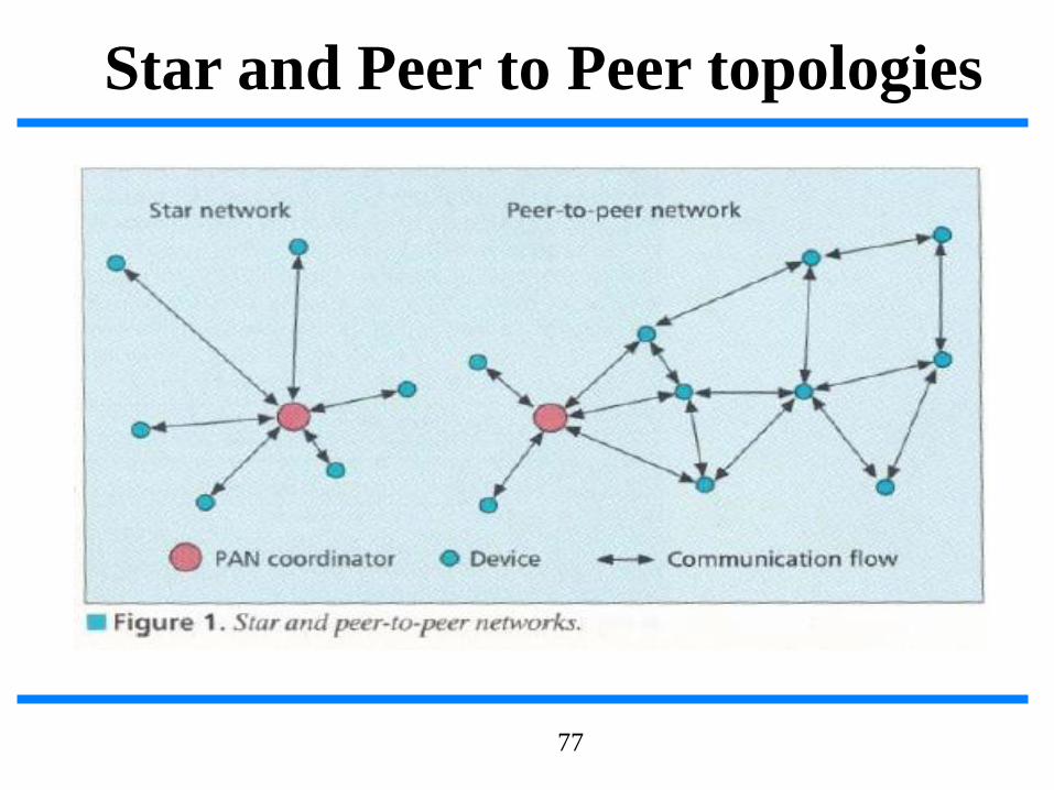
Star and Peer to Peer topologies
77

Data link layer
❑IEEE 802 splits DLL into MAC and LLC
sublayers.
❑LLC is standardized and is common in
802.3,802.11,802.15.1.
❑features of the IEEE 802.15.4 MAC are
association and disassociation, acknowledged
frame delivery, channel access mechanism, frame
validation, guaranteed time slot management, and
beacon management.
78

MAC
❑MAC provides data and management services to upper
layers
❑The MAC management service has 26 primitives
whereas 802.15.1 has about 131 primitives and 32
events,
❑802.15.4 MAC is of very low complexity, making it
very suitable for its intended low-end applications,
albeit at the cost of a smaller feature set than 802.15.1
(e.g., 802.15.4 does not support synchronous voice
links).
79

MAC frame format
80

MAC frame
❑Frame control field indicates the type of MAC frame
being transmitted, specifies the format of the address
field, and controls the acknowledgment.
❑Multiple address types : 64 bit physical address and
short 16 bit network assigned address are provided.
❑Address field size may vary from 0 to 20 bytes.
❑Payload field is variable with condition size of mac
frame <= 127 bytes.
❑FCS is used for integrity check using 16 bit CRC.
81

Superframe
❑Certain applications require dedicated bandwidth toachieve low latency for this it can operate in optionalsuperframe mode
❑PAN coordinator, transmits superframe beacons inpredetermined intervals which is divided into 16 timeslots
❑The channel access in the time slots is contention-basedbut PAN coordinator may assign time slots to a singledevice requiring dedicated bandwidth or low-latencytransmissions. These assigned time slots are calledguaranteed time slots (GTS) and together form acontention-free period.
82

Superframe structure
83

Other MAC features
❑In a beacon-enabled network with superframes, a slotted carrier
sense multiple access with collision avoidance (CSMA-CA)
mechanism is used.
❑In others standard CSMA-CA is used I.e it first checks if
another device is transmitting in the same channel if so backs
off for certain time.
❑MAC confirms successful reception of data with an
acknowledgement.
❑The IEEE 802.15.4 draft standard provides for three levels of
security: no security of any type ,access control lists (non
cryptographic security) and symmetric key security, employing
AES-128.
84

PHY layer
❑This standard provides 2 PHY options with
frequency band as fundamental difference.
❑2.4 GHz band has worldwide availability and
provides a transmission rate of 250 kb/s.
❑The 868/915 MHz PHY specifies operation in the
868 MHz band in Europe and 915 MHz ISM band in
the United States and offer data rates 20 kb/s and 40
kb/s respectively.
❑Different transmission rates can be exploited to
achieve a variety of different goals.
85

Channel structure
86

Channelization
❑27 frequency channels are available across all the 3
bands.
❑This standard includes the necessary things to implement
dynamic channel selection to avoid interference.
❑The PHY layers contain several lower-level functions,
such as receiver energy detection, link quality indication,
and channel switching, which enable channel assessment.
❑These functions are used by the network to establish its
initial operating channel and to change channels in
response to a prolonged outage.
87

PHY layer packet structure
88

Modulation
89
Interference
❑Interference is common in 2.4 GHz band because of
other services operating in that band
❑IEEE 802.15.4 applications have low QOS
requirements and may need to perform multiple
retries for packet transmissions on interference.
❑Since IEEE 802.15.4 devices may be sleeping as
much as 99.9 percent of the time they are
operational, and employ low-power spread spectrum
transmissions, they should be among the best of
neighbors in the 2.4 GHz band.
90

Bluetooth vs IEEE 802.15.4.
❑Bluetooth based WPAN
❑Few devices
❑Data range is 10m to 100m
❑Data rate is nearly 1Mb/s
❑Power consumption is a low.
❑Battery life is low.
❑Star only.
❑IEEE 802.15.4 LR-WPAN
❑Many devices
❑Data range is nearly 10m
❑Data rate is 20 kb/s,40kb/s,250kb/s.
❑Power consumption is ultra low.
❑Battery lasts years.
❑ peer to peer,Star.
91

ZIGBEE alliance
❑ The Zigbee Alliance is an association of companies involved with building higher-layer standards based on IEEE 802.15.4. This includes network, security, andapplication protocols.
❑ A rapidly growing, worldwide, non-profit industry consortium consisting ofLeading semiconductor manufacturers, Technology providers, End-users.
❑ An Organization with a mission to define reliable, cost-effective, low-power,wirelessly networked, monitoring and control products based on an open globalstandard.
❑ Now? Targeted at home and building automation and controls, consumerelectronics, PC peripherals, medical monitoring, and toys
❑ Primary drivers are simplicity, long battery life, networking capabilities, reliability,and cost
❑ Alliance provides interoperability, certification testing, and branding.
❑ Six promoter companies – Honeywell, Invensys, Mitsubishi, Motorola, Samsungand Philips
❑ A rapidly growing list (now almost 60 participants) of industry leaders worldwidecommitted to providing ZigBee-compliant products and solutions
92

ZIGBEE advantages
❑ over proprietary solutions?
❑ Product interoperability
❑ Vendor independence
❑ No more having to invest resources to createa new proprietary solution from scratch everytime
❑Companies now can leverage these industrystandards to instead focus their energies onfinding and serving customers.
93

❑Micaz follows mica line with 51
pin connector and compatibility
with previous sensor boards and
applications.
❑wireless Communications with
Every Node as Router Capability
❑ Telos module is programmedthrough the onboard USBconnector.
❑New single board design withUSB for ultra low power
❑Hardware link-layerencryption and authentication
94
Micaz Telos

❑ Small patch antenna connects through MMCX connector. MMCX connector allows for remote antenna.
❑ Maintains compatibility with previous mote generations/sensors
❑ Get 15.4 to people quickly to startwork with it
❑ Programming and data collectionvia USB
❑ Fast wakeup from sleep.
❑ Telos has two antenna options
❑ New architecture = new low powermechanisms.
❑ Telos leverages emerging wirelessprotocols and the open sourcesoftware movement.
95
Micaz Telos
❑ MicaZ (AVR)
❑ 0.2 ms wakeup
❑ 30 mW sleep
❑ 6 mW active
❑ 45 mW radio
❑ 250 kbps & 2.5V min
❑ 2/3 of AA capacity
❑ Telos (TI MSP)
❑ 0.006 ms wakeup & 2 mW sleep
❑ 0.5 mW active & 45 mW radio
❑ 250 kbps & 1.6V min
❑ 7/8 of AA capacity258 days 584 days
On a pair of AA batteries with a 1% duty cycle using TDMA or low power listening:
0.01 * (active current) + 0.99 * (sleep current) = avg current battery capacity / avg current = lifetime