Embed Size (px)
Citation preview

" LOAN DOCUMENTPHOTOGRAPH THIS SHEET
00
oEVL VINVENTORY
DOCUMENT IDENTIFICATION
a A
-~ ~ N
DDISTRIBUTION STATEMENT L
U14ANNOUNCZD D T0JUSTIFICATION .. k
1I, A , - .
_ _ _ _ _ _ _ _MARI1.,':- -- "ii7 I
D ISTRI UTON I O T TAVAILABILITY CODES
DL'RDfZAAVAJLAiLrry AI4DRR xSPCIALH
DATE ACCESSIONED
DISTRIBUTION STAMPA
RE
DATE RETURNED
94 3 1 006 ý jýi4-08402
DA#RECEIVED IN Dric REGISTERED OR CERTIFIED NUMBER
PHOTOGRAPH THIS SHEET AND RETURN TO DTIC-FDAC
DTI 70 DOCUNVOT PROCESSING SEW"f ma-u B'"" vm w
LOAN DOCUMENT
• , , ' 9tL ,..• .

MODULAR SIMULATOR SYSTEM (MSS)MANAGEMENT GUIDE
K KELLY, J BROWN,G KAMSICKAS, W TUCKER
BOEING DEFENSE AND SPACE GROUPSIMULATION AND TRAINING SYSTEMS499 BOEING BLVDHUNTSVILLE, AL 35824
AUGUST 1993
FINAL REPORT
APPROVED FOR PUBLIC RELEASE; DISTRIBUTION IS UNLIMITED.
SYSTEMS ENGINEERING DIVISION
AERONAUTICAL SYSTEMS CENTERAIR FORCE MATERIEL COMMANDWRIGHT PATTERSON AFB OH 45433-7126

NOTICE
When Government drawings, specifications, or other data are used forany purpose other than in connection with a definitely Government-relatedprocurement, the United States Government incurs no responsibility or anyobligation whatsoever. The fact that the government may have formulated orin any way supplied the said drawings, specifications, or other data, is notto be regarded by implication, or otherwise in any manner construed, aslicensing the holder, or any other person or corporation; or as conveyingany rights or permission to manufacture, use, or sell any patented inventionthat may in any way be related thereto.
This report is releasable to the National Technical Information Service(NTIS). At NTIS, it will be available to the general public, includingforeign nations.
This technical report has been reviewed and is approved for publica-tion.
, USAF JAMES D. BASINGERPro gram Manager Team LeaderSpecial Programs Divsion Special Programs Division
JAMES 3.'OCrNLChief, Systems Engineering DivisionTraining Systems Program Office
If your address has changed, if you wish to be removed from our mailinglist, or if the addressee is no longer employed by your organization pleasenotify ASC/YTS WPAFB, OH 45433-7111 to help us maintain a currentmailing list.
Copies of this report should not be returned unless return is required bysecurity considerations, contractual obligations, or notice on a specificdocument.
rtorm Approved
REPORT DOCUMENTATION PAGE [ oMB A 070o4018
~e.sC.~). V 1 2618 . "" . .'.O A)C. OM 1 r " 9?-'''*' ~ ed .¶4'I . t'9 e 348) l 01 A~s ' t" &w05t03
1, ALENCY USE ONLY (Leave blank) 2 REP56•T 9 ,J• 93 3 REPORT T L DATES COVERED
4. TITtE AND SUBTITLE S. FUNDING NUMBERS
Modular Simulator System (MSS)Management Guide F33657-86-C-0149
64227F6. AUTHOV(•) Kelly, J. Brown
G. Kamsickas, W. Tucker
7. PERFORMING ORGANIZATION NAME(S) AND ADDRESS(ES) 8. PERFORMING ORGANIZATION
Boeing Defense and Space Group REPORT NUMBER
Simulati-n and Training Systems499 Boeing Blvd S495-10459-1Huntsville, AL 35824
9. SPONSORING /MONITORING AGENCY NAME(S) AND ADDRESS(ES) 10. SPONSORING / MONITORING
Aeronautical Systems Center AGENCY REPORT NUMBER
Systems Engineering Division ASC-TR-94-5008Bldg 11 2240 B St Ste 7Wright-Patterson AFB, OH 45433-7111
11. SUPPLEMENTARY NOTES
12a. DISTRIBUTION / AVAILABILITY STATEMENT 12b. DISTRIBUTION CODE
Approved for public release;distribution is unlimited.
13. ABSTRACT (Maximum 200 words)
This document provides guidance and reference information for managementpersonnel in the use of the Modular Simulator System (MSS) designprinciples. It identifies those unique management considerationsrequired when employing the modular simulator design to a simulationand/or training device. This guide serves as both an educational anddecision tool for the manager. The guide will educate the manager inthe basic concepts of the modular simulator design and its basis fordevelopment. Key program decisions and considerations that must be madewhen using the modular simulator design are identified and discussed.The advantages and disadvantages of using the modular simulator designalong with associated cost/risk analysis, logistics impacts, managementimplications, lessons learned and basis for invoking the modularsimulator design on a procurement/program are provided.
14. SUBJECT TERMS I. NUMBER OF PAGES
Modular Simulator System (MSS) 16. PRICE CODE
17. SECURITY CLASSIFICATION 18. SECURITY CLASSIFICATION 19. SECURITY CLASSIFICATION 20. LIMITATION OF ABSTRACTOF REPORT OF THIS PAGE OF ABSTRACT
UNCLASSIFIED UNCLASSIFIED UNCLASSIFIED ULNSN 7540-01-280-5500 'Standard Form 298 (Rev 2-89)
Prescribed by ANSI Std Z39-18298-102

THIS PAGE INTENTIONALLY LEFT BLANK
2

Abstract
This document provides guidance and reference information for management person-nel in the use of the Modular Simulator System (MSS) design principles. It identifiesthose unique management considerations required when employing the modular sim-ulator design to a simulation and/or training device. This guide sewves as both aneducational and decision tool for the manager. The guide will educate the managerin the basic concepts of the modular simulator design and its basis for development.Key program decisions and considerations that must be made when using the modu-lar simulator design are identified and discussed. The advantages and disadvantagesof using the modular simulator design along with the associated cost/risk analysis,logistics impacts, management implications, lessons learned and basis for invokingthe modular simulator design on a procurement/program are provided.
D495-10439-1 3
Table of Contents
Section Page
1. INTRODUCTION. 71.1 Purpose. 71.2 Scope. 7
2. REFERENCE DOCUMENTS. 8
3. MODULAR SIMULATOR DESIGN OVERVIEW. 93.1 Modular Simulator Concept. 93.2 Application of the Modular Simulator Design. 143.2.1 Benefits of the Modular Simulator Design. 163.2.2 Common Misconceptions RegardingModular Simulator Design. 173.3 Other Related Standards and Processes. 193.3.1 Distributed Interactive Simulation (DIS). 193.3.2 Project 2851. 193.3.3 Simulator Data Integrity Program (SDIP). 193.3.4 Universal Threat System for Simulators (UTSS). 19
4. MODULAR SIMULATOR PROGRAM MANAGEMENT. 214.1 Management Overview. 214.2 Schedule. 214.2.1 Schedule Risk. 234.2.2 Program Phasing and Milestones. 234.3 Cost. 264.4 Risk 274.5 Staffing. 294.6 Subcontract Management and Procurement Philosophy. 294.7 Development Environment. 344.8 Logistics Considerations. 354.9 Facilities Considerations. 364.10 Lifecycle Considerations. 36
5. MANAGEMENT LESSONS LEARNED. 385.1 Specifications/Interfaces. 385.2 Subcontract Management. 39
D495-10439-1 4
5.3 Segment Testing. 405.4 Logistics/Implementation. 415.5 Testing/Integration. 42
6. NOTES.6.1 Acronyms and Abbreviations. 44
C!;' D495-10439-1 5

List of Figures
Figure Page
3.1-1 Modular Simulator System Development Process 103.1-2 Modular Simulator System Partitioning Process 113.1-3 Modular Simulator System Generic Specification Organization 133.1-4 Modular Simulator System Architecture 154.2-1 Modular Simulator System Development Schedule Comparison 224.2-2 Modular Simulator System Preferred Segment Integration Order 244.4-1 Modular Simulator System Back Door Interface 284.5-1 Modular Simulator System Skill Mix 304.6-1 Modular Simulator System Development Team Segment Allocation 32
r
Sru,95-10439-1 6
1. INTRODUCTION.
1.1 Purpose. The purpose of this document is to provide guidance and referenceinformation for managers who are considering the Modular Simulator System (MSS),or "Mod Sim" approach to simulator development. This guide serves as both an edu-cational and decision tool for the manager. The guide will educate the manager in thebasic concepts of the modular simulator design and its basis for development. Keydecisions and considerations that must be made when using the modular simulatordesign are identified and discussed.
1.2 Scope. This management guide is applicable to a Mod Sim design basedprogram. It identifies those unique management considerations required whenemploying the modular simulator design to a simulation and/or training device. Theadvantages and disadvantages of using the modular simulator design along with theassociated schedule, cost, risk, support, and management considerations arediscussed. Lessons learned during the demonstration project to develop an F-I 6Csimulator using the Mod Sim approach are also provided. This guide is focused onmanagement, specifically toward the first level supervisor, engineering manager, andproject manager. It is intended to assist this level of management in the developmentof a program management plan for a Mod Sim based project.
Throughout this document the terms 'prime contractor', 'system integrator, 'systemdeveloper, 'subcontractor, 'supplier, and 'segment developer' are used. The primecontractor is the company responsible for delivery of the end system to the customer.In most cases, the prime contractor will also be the system integrator and systemdeveloper. However, this is not a requirement. The task of system integration can beassigned or subcontracted to another company. The terms prime contractor, systemintegrator and system developer are used interchangeably in this document. Theterms subcontractor, supplier, and segment developer refer to the person or companyresponsible for the development of a Mod Sim segment. These terms are used inter-changeably in this document. However, it is quite possible and likely that the primecontractor will develop several of the segments for an implementation and will there-fore also be a segment developer.
D 0)D495- 10439-1 7

2. REFERENCE DOCUMENTS.
The following documents are provided fir further reference and would be useful in themanagement and design efforts of a modular simulator design program.
a. System/Sogment Specification for the Generic Modular Simulator System,Volume., i-XIII, S495-10400.
b. System/Segment Specification for the F-1 6C Modular Simulator SystemDemonstrator, Volumes I-XII, S495-10415.
c. Interim Report on Research and Development for Modular Simulator SystemPhase III Program, Part 1, D495-10402-1, 15 September 1988.
d. Modular Simulator Design Program, Phase III, Part 2 Final Report,D495-10437-1, 29 August 1991, Revision B.
e. Follow-on Effort Final Report for the Modular Simulator Design Program,D495-10438-1, 28 August 1991.
f. Modular Simulator Engineering Design Guide, D495-10440-1.
g. Interface Requirements Specification for the Generic Modular SimulatorSystem, S495-10734.
h. Interface Design Document for the Generic Modular Simulator System,D495-10735-1.
i. Modular Simulator Executive Report, D495-10441-1
0D495-10439-1 8
3. MODULAR SIMULATOR DESIGN OVERVIEW.
3.1 Modular Simulator Concept. The Modular Simulator System (Mod Sim) Designprogram was a tri-service supported development program. The primary goals of themodular simulator design are to shorten simulator development schedules, reducesimulator development costs and improve simulator supportability. To achieve thesegoals a generic Weapon System Trainer (WST) was partitioned into a discretenumber of modules or segments. Specifications that define/standardize eachsegments functions and a method for intersegment communication were thenprepared.
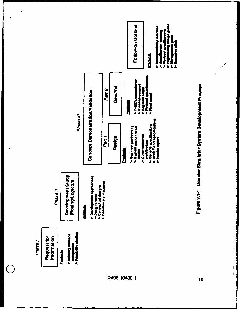
The development of the Mod Sim was accomplished using the three phase processshown in Figure 3.1-1. Phase I consisted of a Request For Information (RFI) to thesimulation industry. The purpose of this RFI was to survey the simulation industry toassess the industry's desire for and the general feasibility of the modular simulatorconcept. The results of this survey were very positive. This led to the Phase II,Modular Simulator Design Concept Development. This was a competitiveprocurement awarded to two companies, Boeing and Logicon. The products of thisphase were a conceptual modular simulator architecture with a focus on aircrew sim-ulator functional analysis and intermodule communication architecture/design. Eachcontractor developed a conceptual modular simulator design for this effort. Thecontractor's conceptual design formed the basis for their proposal for the Phase IIIcontract. Boeing was awarded the Phase III contract, which consisted of design,demonstration and validation of the modular simulator concept.
To foster industry participation and "buy in" to the Mod Sim design, Boeing wasrequired to subcontract the design and development of 50 to 75 percent of thesegments. The Phase III subcontractors were Rediffusion Simulation Limited (RSL),Science Applications International Corporation (SAIC), AAI, and Intermetrics. To gainfurther industry participation, regular Interface Standards Working Group (ISWG)meetings were held. At these meetings both industry and government simulationexperts were allowed to participate in the review of the modular simulator design andsubsequent demonstration.
Phase Ill was divided into two parts. During Part 1, Boeing and the Boeingsubcontractors accomplished four major tasks:
a. System Partitioning. The process for this task is shown in Figure 3.1-2. Thistask involved the analysis of simulations for a large number of fixed and rotary wingtraining devices. Each simulation was broken down to its low level objects andfunctions. This data, along with other raw data and the conceptual partitioning fromPhase II were used to create a Functional Dictionary that contained an allocation of all
D495-10439-1 9
I A IjI + I,+- j jitIAAAA
cI
IO
0.a iiiS L)
-. BmillZ
D495-10439-1 10
IIII

I©
ci
IA i II I IIII
120'LI
cJABccIAC
D95-104391 P

functions and the interface requirements between functions. The FunctionalDictionary and segment partitioning were refined through an iterative process usingan Artificial Intelligence tool. This resulted in segments that had generic intersegmentinterfaces,were loosely coupled, and focused on a specific area of simulationexpertise
b. Communication Architecture. This task involved the identification and spec-ification of a hardware and software communication architecture that would allow thesegments to communicate effectively. The communication architecture had to be ofa non-proprietary design, support industry standards, exhibit low data latency, provide50% growth and be available for use in the concept demonstration.
c. System Performance Model. In order to efficiently select a communicationarchitecture a System Performance Model was constructed to emulate the variousdesign alternatives. Fourteen data buses and seven protocols were analyzed. Thecommunication architecture selected was the Fiber Distributed Data Interface (FDDI)coupled with the Xpress Transfer Protocol (XTP).
d. Specifications. To promote the standardization of the Mod Sim architecture,a thirteen volume generic System/Segment Specification (DOD-STD-2167A) wasprepared. The organization of this specification is shown in Figure 3.1-3. The systemlevel specification defines the communication architecture and requirements commonto all segments. The segment level specifications define the unique requirements
(i applicable to the segment.
During Part 2 of Phase III, Boeing and the Boeing subcontractors demonstrated themodular simulator design developed in Part 1. The demonstration was accomplishedusing a government provided F-16 crew station and existing F-16 simulator sourcecode. The government furnished products were adapted to the modular simulatorpartitioning and communicated using the modular simulator communicationarchitecture. Other tasks accomplished during Part 2 included the development of aSegment Tester tool, used to test individual segments prior to integration into thesystem, and further refinement of the generic system/segment specifications basedon lessons learned during the demonstration.
At the completion of the Phase III, Part 2 demonstration, several follow-on tasks werecontracted to Boeing. These consisted of adding an interface to the Mod Simarchitecture to support multiple simulator/team training (e.g.; Distributed InteractiveSimulation), adding tailoring instructions to the genedc specifications to ease adapta-tion to specific applications, and the creation of Mod Sim guidance documentation.This documentation included an engineering design guide, a management guide andan executive report that provides an overview of the Mod Sim approach.
D495-10439-1 12

>>
pC
0
iii I
=E
liIc - -b
IT I
L w,EE (3
(j.D495-1I0439-1 13
The current Mod Sim architecture is shown in Figure 3.1-4. The architecture consistsof 12 distinct segments that communicate via a Virtual Network (VNET). The ModSim communication architecture was revised to the VNET to make the Mod Sim com-munication architecture independent of a specific hardware implementation. Thisallows the architecture to be more adaptable to high end and low end applications andfurther adaptable to advances in computer technology. The VNET is a conceptualmechanism for communication between segments using the message passing proto-col regardless of the hardware implementation. The FDDI/XTP version of thecommunication architecture remains the default implementation.
3.2 Application of the Modular Simulator Design. The modular simulator design isapplicable to all types of aircrew training devices for both rotary wing and fixed wingaircraft including Weapon System Trainers (WST), Operational Flight Trainers (OFT),Cockpit Procedures Trainers (CPT) and Part Task Trainers (PTT). With minor modifi-cations the Mod Sim design has been applied to land and sea based vehicles. TheEnvironment segment also promotes the application of the Mod Sim design tonetworked as well as stand-alone training devices.
One of the questions frequently asked about Mod Sim is "Should I use the Mod SimDesign in my application?'. In most cases the answer is yes. To determine if a specificapplication would benefit from a Mod Sim design the answers to the followingquestions should be reviewed.
a. Does the application involve a family of trainers? If the application involvesthe development of a WST and a CPT for the same aircraft then it would be beneficialto use the Mod Sim design. Entire segments could be reused on each device. Thisreduces development time and cost through segment reuse. Each segment is treatedas an individual product that can be developed, tested, documented, and managedonce and then reused several times.
b. Will your application require modifications or upgrades during developmentor after deployment? The modular simulator design provides a loose coupling ofsegments and well defined intersegment interfaces. This characteristic isolates andencapsulates changes to the training devices. For example, the upgrade to a visualsystem or addition of a motion system would only affect the Visual and Physical Cuessegments respectively. An upgrade in fidelity or functionality of the simulation in anysegment would, in most cases, only affect the internal design of that segment.
Maximum leverage will occur when the Mod Sim approach is applied to new simulatordevelopments. New developments allow the Mod Sim principles to be applied fromthe ground up. This takes full advantage of the front end systems engineering work
0 D495-1 0439-1 14

UlU)
C
C 0
LL- 0490 15

that has been done in the generic system/segment specications and intersegmentinterface definitions. The Mod Sim design approach can also be applied to existingsimulation devices that are undergoing modification or upgrade. It is recommendedthat trade studies be performed to determine if it is cost effective to repartition anexisting device into a Mod Sim architecture. In most cases a significant upgradewould be required to justify the cost of a total system redesign. Care should also betaken to avoid a "beat-to-fit" application of the Mod Sim design just for the sake ofcreating a modular simulator.
3.2.1 Benefits of the Modular Simulator Design. There are several distinct advantag-es to using the modular simulator design and design concepts in developing trainingdevices. These advantages include:
a. Systems Engineering. The Mod Sim design provides a wealth of genericsystems engineering products that are reusable for any application. These productsinclude the generic System/Segment Specifications, Interface RequirementsSpecification, and Interface Design Document. Each of these products include tailor-ing instructions and guidance to create application specific documents from thegeneric products. This reduces front end development cost and schedule andmitigates risk throughout the project.
b. Subcontracting. One of the primary requirements for the Mod Sim architec-ture was the capability to independently specify, develop, and test individual
Ssegments as stand-alone products. This enhances the ability to subcontract develop-ment of segments by providing well-defined interfaces that reflect a straight-forwardallocation of simulator functions along traditional subsystem product boundaries. Thisallows the prime contractor to more readily take advantage of expertise in other com-panies, create teaming agreements, or develop workshare allocations both internaland external to their company. The generic specifications and interface definitionsprovide a strong foundation for defining subcontracting/teaming agreements.
c. Integration. Use of the Mod Sim architecture can significantly reduceintegration time. Because each of the Mod Sim segments are individually testedbased on a well defined system interface prior to integration, the probability of findingmajor problems during integration is virtually eliminated. This was proven during theMod Sim F-16C demonstration project. System integration was accomplished inseveral weeks versus the usual several months.
d. Reusability. The Mod Sim architecture promotes reuse among families oftraining devices and can also support reuse among different training deviceapplications. The generic specifications and system interfaces have identified a largenumber of commonalities and variabilities to allow for the design of reusablesegments and communication architectures.
D495-10439-1 16

*. Design Flexibility. The Mod Sim architecture allows latitude in design tosupport low cost and high cost devices. The Mod Sim architecture does not place anyrequirements on the internal design of the segments. A segment developer is free todetermine the best design solution for their segment.
f. Parallel Development and Stand-alone Testing. Mod Sim segments can bedeveloped and tested in parallel due to the well defined segment requirements andintersegment interfaces. This can significantly shorten the overall systemdevelopment schedule and reduces integration risk by eliminating common interfaceproblems early in the development and testing phases.
3.2.2 Common Misconceptions Regarding Modular Simulator Design. During the de-velopment and demonstration of the Mod Sim design, no major disadvantages wereidentified. However, several misconceptions have developed as the programprogressed. A manager should be aware of them and consider the facts to make aninformed decision. These common misconceptions include:
a. Hardware Solution to a Software Problem. The original modular simulatorconcept was based on partitioning the system into distinct stand-alone segmentscomposed of all hardware and software components necessary to meet the segmentperformance requirements. Each segment would communicate with other segmentsvia a rigidly defined network using a predefined protocol. Some individuals felt thatthis hardware partitioning was done to force the software into a more modular
( architecture. This was not the case. The Mod Sim architecture allows for a widerange of design solutions involving both hardware or software alternatives.
b. Use of FDDI. The original Mod Sim design used FDDI as the communicationmedia. FDDI was selected based on a worst case analysis of communication trafficfor a WST. The current Mod Sim architecture embraces a "Virtual Network" concept.The virtual network concept supports the use of a communication architecture thatbest fits the requirements of the application. For example, a low cost, low bandwidthapplication may use ethernet or reflective memory. FDDI is still specified in thegeneric specification for the Mod Sim since this is the architecture that was tested anddemonstrated for the proof of concept. The specifications may be tailored toaccommodate other alternatives based on the specific application.
c. Architecture Too Rigid. The generic Mod Sim architecture is based on 12separate and distinct segments. This approach was selected to maximize large scale,whole segment reuse. The current architecture has adopted the .Rpproach thatsegment software may be combined into a single hardware platform or computationalsystem. However, the segment software must still be stand-alone and communicatewith other segments via the intersegment interfaces. In general, the segments shouldnot be aware that they reside in the same machine. This promotes maximum
(9 software reuse.
D495-10439-1 17
d. No Successful Full Scale Demo. The Mod Sim demonstration involvedrehosting existing software that was repartitioned to the Mod Sim architecturerequirements. Because of the classified nature of portions of the F-16 software,several segments were not fully developed but "emulated" to generate representativeintersegment data transfer. The goal of the demonstration was to prove the communi-cation architecture and Mod Sim approach, not to show how welt a simulation couldbe developed. The communication architecture was fully loaded as if the F-16demonstrator was a full scale simulation. The communication architecture performedwithin the modeling predictions and provided acceptable performance. It should benoted that the Mod Sim architecture has since been applied to other simulator applica-tions both within and external to Boeing.
e. Specifications. The original Mod Sim generic specifications and interfacedata were deemed difficult to understand and use by industry. Because of thisconcern, Boeing incorporated tailoring instructions in the specifications to help othercontractors better understand and apply the Mod Sim architecture. To ensuremaximum understanding, the tailoring instructions were developed by engineers whowere not part of the original development effort.
f. Message Passing. The Mod Sim architecture uses message passing totransfer data between segments. This method of communication was thought to betoo slow for real time simulation. This is not the case. The Mod Sim proof of concept(F demonstrated that message passing would work. Even at worst case only 6% of theFDDI bandwidth was used. Message passing has been used in many real time appli-cations other than Mod Sim in the past.
g. Functional Decomposition. One complaint is that Mod Sim dictates afunctional decomposition versus an object oriented decomposition. The Mod Simarchitecture is not intended to force any specific software architecture within asegment. Software design internal to the segment is at the discretion of the segmentdeveloper and may be of any design methodology. The top level segment partitioningwas determined based on several factors including; domain expertise,subcontractability, functionality, simulation industry trends, communicationperformance, etc. Each of the segments deal with a recognized discipline within thetraining system industry. These are high level disciplines which traditionally fall withinestablished product line boundaries and involved specific technical specialities suchas image processing, audio processing, electromechanics, aerodynamic modeling,electronic combat modeling, etc. Segment functionality was allocated to maximizethe potential for specialization while considering technology trends. Specializationinvites increased competition by breaking large applications into subsystems that canbe built by smaller suppliers. Complexity and quantity of data flow between segmentswas also considered in the allocation to reduce the interdependence of the segments.In summary, there was no specific, traditional decomposition methodology employed.
D495-10439-1 18

A review of the segments shows that some have a functional nature, such as FightDynamics, others have a traditional simulator subsystem nature, such as Visual, andsome have an object oriented nature, such as Propulsion.
h. Mod Sim Validation. The criteria for a device to be considered a "Mod Sirm*is unclear. Industry was unsure which parts of the Mod Sim architecture were requiredand which were optional. To help better define the boundaries of Mod Sim, Boeingprepared tailoring instructions for the generic specifications and a Mod Sim designguide. These two documents provide the guidance necessary to competently applythe Mod Sim design principles.
i. Proprietary. There is a misconception that Mod Sim is a proprietary Boeingproduct. It is not. Boeing was the prime contractor for the Mod Sim development TheMod Sim architecture is intended to be used throughout the simulation industry and isa public domain development. Boeing and the government freely distributeinformation on the Mod Sim design.
3.3 Other Related Standards and Processes. There are several other DoD initiativesthat involve the standardization of simulators and training systems. The Mod Simarchitecture does not constrain the use of these standards. In fact, some characteris-tics of the architecture were designed to accommodate or enhance compatibility withthese standards.
C- 3.3.1 Distributed Interactive Simulation (DIS). The Mod Sim architecture supportsmultiple simulator operations, such as those provided by the DIS protocol. Theenvironment segment provides a seamless connection between the Mod Simsegments and the multiple simulator environment. All remaining segments, exceptthe Instructor/Operator Station (lOS), function the same in multiple simulator andautonomous operations.
3.3.2 Project 2851. Project 2851 is working to standardize visual and radardatabases. Project 2851 causes no impact on the Mod Sim architecture. The use ofdatabases are internal to the segments who use the databases. These segmentsinclude Visual, Radar, and Environment. Database information is not communicatedvia the Mod Sim communication architecture during real-time operations.
3.3.3 Simulator Data Integrity Program (SDIP). The SDIP has developed standardsfor supplying and specifying design data for simulation devices. This has no affect onthe Mod Sim design or architecture. The SDIP standards should be used whendeveloping any simulation device to avoid or reduce design criteria problems.
3.3.4 Universal Threat System for Simulators (UTSS). UTSS is in the process ofdeveloping common or reusable threat databases. Once again, the affect of this
D495-10439-1 19

initiative will be internal to ft Mod Sim segments. In the current Mod Simarchitecture, the environment segment provides the simulation of the external threatenvironment and the electronic warfare segment provides the simulation of theownship Electronic Warfare (EW) equipment. The only segments that would be inter-nally affected by UTSS will be electronic warfare and environment.
D495-10439-1 20

4. MODULAR SIMULATOR PROGRAM MANAGEMENT
4.1 Management Overview. The management of a Mod Sim based simulatordevelopment is very similar to a traditional simulator development. There are still theday-to-day management activities associated with cost, schedule and resource(personnel, equipment, data, etc.) allocation. The prime contractor plays a systemintegrator and coordination role in the development of the training system. For somecontractors this would not be a change, but for those companies that produce themajority of the training device in-house this could be a drastic change. The primecontractor should posses strong systems engineering and integration skills tosuccessfully implement a Mod Sim. If segments will be developed and furnished bysubcontractors, a strong subcontract management capability is also required,
From a customer viewpoint, a prime contractor should be selected based on their pastsuccessful experience in system integration and demonstration of a broad trainingsystem experience base. At a system level the use of the Mod Sim architecture istransparent to the user. The Mod Sim approach affects the underlying architecture ofthe system to generate a more efficient simulator development in terms of cost,schedule and risk. In the long term, the Mod Sim approach should reduce the cost ofsystem upgrades throughout the life cycle of the system.
4.2 Schedule. There are several scheduling factors to consider when planning a( modular simulator implementation. Figure 4.2-1 provides a comparison between a
typical development schedule and a suggested Mod Sim development schedule.This schedule assumes that the simulation device is a WST of average to aboveaverage complexity, the user requirements are defined and relatively stable, and thedevice requirements, such as those provided by a formal Instructional Systems Devel-opment (ISD) process, are also available. The Mod Sim approach to development ofsuch a system can save approximately 9 months or 20-25% when compared to atraditional development approach for the same device. The supporting rationale forthis estimate is provided in the following paragraphs.
A modular simulator implementation is similar to managing a set of small, individualprograms that require integration at some point. One of the advantages of a Mod Simimplementation is a potentially shorter development schedule. The developmentschedule is shorter due to several factors. First, there is a significant amount of reus-able systems engineering provided by the generic specifications and interfacedesign. These reusable work products reduce the requirements definition and systemlevel design phases considerably. Once the interfaces for the modules/segments aredefined; design, development and stand-alone segment test can occur in parallel foreach segment.
0D495-10439-1 21

.. ... .... 5 a . .
..... ...
- ,,' -*<k b'K.- , -ix
."............. ....... . . . . . . . . . ..
U)t
06 42
<'. .9f99.99.p 9'W t ' w ' ..4 . .....
~. ..'~ .A ." - ... '. .... W.
0 " "- ~ 4.,...............
C.........
..... ...
D45103- 2'2"

The software and segment test phase for a Mod Sim development will typically belonger than traditional software test due to the addition of formal segment stand-alonetesting. Stand-alone segment testing tests each segment as a product when accept-ed from the segment builder or subcontractor. When each of the segments arethoroughly and successfully tested prior to integration, the time required forintegration and system level testing is significantly reduced. Stand-alone segmenttest identifies segment design errors earlier in the development cycle where they cannormally be resolved in less time and at a reduced cost. The use of an automatedsegment testing device can reduce the stand-alone segment testing time significantly.
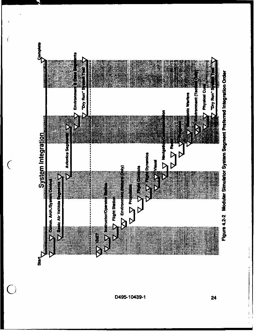
Experience from the development of the F-16C simulation device developed duringthe Mod Sim demonstration program showed reductions in system integration andsystem level test. This experience shows that integration and system level testingtime can be reduced by at least 40 and 10 percent respectively when compared withtraditional simulation device development. It should be noted that there is a preferredorder for integration of the segments into the system. This is shown in Figure 4.2-2.The rationale for this sequence is provided in the "Modular Simulator EngineeringDesign Guide".
4.2.1 Schedule Risk. Schedule risk is inherent in any program. However, two phasesin the Mod Sim development schedule are noteworthy when segments are developedby subcontractors. First, schedule risk may increase when the subcontractors are
(" provided with contractor furnished equipment or data. For example, it may be costeffective for the prime contractor to make or buy hardware and software componentsthat are common to several segments, such as computational equipment and theinterface to the Virtual Network In such cases, schedule reserve may be necessaryto insure that procurement or development schedule problems incurred by the primecontractor do not impact the segment suppliers. A second schedule risk factorinvolves stand-alone segment test completion and the start of integration. Again,schedule reserve may be necessary to negate adverse integration schedule impactsdue to late segment delivery from a supplier. The amount of schedule reserve willdepend on the level of risk associated with each situation. For example, the primecontractor may have a common, fully tested, off-the-shelf VNET interface or a suppliermay have an off-the-shelf segment, thereby reducing or eliminating associated sched-ule risk and the need for schedule reserves.
4.2.2 Program Phasing and Milestones. A Mod Sim implementation is compatiblewith MIL-STD-1521 program phasing and risk reduction milestones. However, sever-al of the typical MIL-STD-1521 meetings and reviews between the prime contractorand the customer can be held sooner in a Mod Sim implementation. Many aspects ofthe front end systems engineering and system design are provided in the genericsystem/segment specifications and the modular simulator design/management
0D495-10439-1 23
.' .. ., .
IS rS
..........
...... .o ...
c'.,
D45103- 24
guides reducing time necessary to develop the top level system architecture. Effo•tcan be focused on understanding the requirements specific to the application.Guidance for the more prominent customer reviews is as follows:
a. System Requirements Review (SRR). SRR should probably still be held atthe typical 30 days after contract award. This allows the prime contractor and thesubcontractors to come to a common agreement and understanding of the systemlevel and supporting segment level requirements. The prime contractor and thesegment suppliers should be working very closely during this initial 30 days. It issuggested that the development team be collocated during this time to increaseproductivity, foster team building and reduce feedback time. This would also fulfill therequirement for a supplier SRR.
b. Preliminary Design Review (PDR). PDR can be held significantly earlier ina Mod Sim development, possibly as early as 30 days after SRR. This assumes thata detailed Prime Item Development Specification (PIDS) is available at the SRR. Bythe end of SRR each segment should have a concise specification and a set of welldefined, compilable, external interfaces. The system level specification will becompleted and the system level design should be documented and allocated to eachof the team members. The remaining tasks to get to PDR will consist of internalsegment preliminary design and creation of the top level hardware drawings. Thesetasks could be completed in 30 to 90 days. The Mod Sim approach can save approx-imately three months in the preliminary design phase.
c. Critical Design Review (CDR). The Mod Sim approach does not dramatical-ly accelerate the detailed design phase that occurs between PDR and CDR. Someschedule improvement may be enabled by parallel development of the segments.However, parallel development is also possible in traditional simulator developments.In a traditional simulator development, detail design is normally done in parallel bysmaller design teams. It is likely that the Mod Sim approach can save approximatelyone month during the detailed design phase due to the sound systems engineeringfoundation created early in the project and reduced coupling between the segments.
d. Test Readiness Review (TRR). A TRR will be held for the system leveltesting. This will be after the development, segment test and integration phases. Thetiming for the TRR will be earlier than for a traditional development effort. A portion ofthe traditional software tests will be accomplished during segment testing, resulting ina shorter software test period. The segment test period, which is unique to Mod Sim,will increase lower level testing due to a longer and more rigorous stand-alonesegment test period. However, the integration period will be significantly shorter asdiscussed earlier, offsetting the longer test period. The TRR itself can potentially belonger in duration. The data from segment testing could be reviewed by the customerrequiring an extra I to 2 days. This data would be in addition to the typical review ofcontractor run system level test results. At least two months can be saved during the
D495-10439-1 25

time between CDR and the TRR using the Mod Sim approach.
Typical MIL-STD-1521 meetings were conducted for the modular simulatordemonstration device development and were successful. The only problemencountered with the demonstration device meetings was preparation time. Thisproblem is not unique to a Mod Sim implementation and may occur whenever subcon-tractors are involved. Preparation for the meetings is longer due to the subcontractingof the design effort for a large number of segments. For example, in preparation forcustomer CDR, major supplier CDRs were held with all segment developers. Thishad to occur several weeks in advance of the customer CDR in order to review andresolve supplier designs and integrate supplier briefings into the customer CDR.There are options to this approach that can save time but may involve some risk. Oneoption is to allow the subcontractor to prepare and present their respective portion ofthe design at the customer CDR. To reduce the risk of the supplier not beingprepared, dry runs chn be held prior to the customer review. To reduce the rework ofpresentation materials, chart formats, media and graphics software should becompatible among team members to ensure changes can be made rapidly and chartscan be modified by the prime contractor if changes are required. The prime contractorshould allocate a small amount of additional time (3 to 5 days) for segment supplierreviews prior to customer reviews as a minimum.
4.3 Cost. One of the major goals of the modular simulator architecture is to reducethe overall cost of the end product, the training device(s). Cost savings are normally( a result of savings in several areas, such as reduced schedules and higherproductivity. Based on the results of the Mod Sim demonstration project, engineeringestimates from Mod Sim based proposal efforts, and future projections, the Mod Simarchitecture is predicted to reduce the cost of training devices. The most significantcost reductions will occur in the following areas:
a. Schedule. The schedule for a modular simulator program will be shorterdue to parallel development of segments, shorter integration due to more extensivesegment testing, and less retest in system level testing.
b. Reuse. The potential for reuse of segments is enhanced in a Mod Simimplementation. Reuse can occur in two places, reuse of segments in different devic-es within the same training system and reuse of segments from previous programs.The reuse of segments must be planned at proposal time and managed throughoutthe program. Reuse will not happen of its own accord. Reuse among devices withina specific training system (e.g.; WST and CPT) may be possible for many applicationspecific segments such as Flight Controls, Flight Dynamics, Flight Station,Propulsion, etc. Reuse from program to program is normally more difficult to achievefor these segments. However, some key segments such as Visual, lOS, and Environ-ment lend themselves to wide scale reuse across multiple programs.
D495-10439-1 26

c. Problem Avoidance, Detection and Resolution. One of the major costdrivers in simulation device development is resolution of uted problems. Ithas been shown that the cost of resolving a problem grows exponentially as youapproach the end of system level testing. The Mod Sim approach addresses thisissue through two paths; generic front end systems engineering that has anticipatedcommon simulation development problems and rigid segment testing that detectsproblems early in the test program. Management should ensure that these two areasare addressed properly during program planning and performance.
4.4 Risk. Architecture development and integration risk in a Mod Sim based designeffort is very low. Many of the high level program and design issues have either beenresolved or a process has been identified to aid in the resolution of these issues. TheMod Sim approach provides a proven method for specifying and idbntifying theinterfaces for all major system components. This reduces the typically highintegration risk associated with simulator development. The tailoring instructions builtinto the generic specifications and interface documents promote risk reduction byidentifying specification and interface alternatives along with how the alternatives mayaffect the design. The "Modular Simulator Engineering Design Guide" and this docu-ment identify key design and program issues and methods for identifying andaddressing these issues.
Although the Mod Sim approach attempts to mitigate a significant amount of develop-ment risk, there will always be program unique areas of risk that the Mod Sim
(f approach cannot anticipate. These areas include integrated avionics, future aircrafttechnology developments, and challenging requirements for Radar and ElectronicWarfare segments. The Mod Sim architecture works well where objects and function-ality can be allocated to one and only one segment, but can be more difficult to applywhen objects and their associated functionalities are complex and span several of theexisting segments. The VNET interface provides a well defined, generic, intersegmentcommunication method that is adaptable to the majority of applications. However, itmay not readily address every possible variability existing in todays aircraft integratedavionics and still maintain its generic quality and design flexibility. To provide asolution to this problem, the Mod Sim architecture allows "back door" connectionsfrom segments to shared system components such as integrated avionics. Figure4.4-1 provides an illustration of typical back door connections. Back door connectionsare not to be used to replace the defined VNET communication path betweensegments. Back door interfaces are special, alternate communication paths thatallow segments to communicate with shared hardware and software components.System components that are connected only to one segment are considered part ofthe segment and not a back door interface.
The back door interface provides the Mod Sim architecture with an added dimensionof design flexibility. The back door interface should be used with care and should be
0 D495- 10439-1 27

JiColI
dc8
E
C~ 0I
0D495-1 049-1 2

adequately documented in the specifications. A plan for the design. implementationand testing of each back door interface must be defined to reduce integration riskWhen used effectively the back door interface design option can be very successful.
4.5 Staffing. Prime contractor staffing for a modular simulator based program isdetermined by the amount of subcontracted effort. Figure 4.5-1 provides a typicalstaffing plan for a Mod Sim development where approximately 50 percent of thesegments have been subcontracted to three external suppliers. In most cases theprime contractor's staff will be primarily systems engineering oriented in the initialphases. Systems engineering will continue to participate in the management ofsubcontracted efforts throughout the project then ramp up slightly during segmentintegration. Design staff will fluctuate based on the number of segments which aresubcontracted. If all the segments are subcontracted then design staff would be min-imal and the systems engineering staff would remain constant or increase slightly tosupport subcontracts management and review subcontractor deliverables. Total testengineering support will remain similar to a traditional program with the exception thatformal test support will be required during stand-alone segment testing to performsegment acceptance. There will be a greater amount of systems engineering workcompleted by the end of the system requirements analysis phase (SRR time frame).In most cases subcontractors will be identified and will be part of the proposal team.Subcontractor specifications, statements of work, and interface definitions must bedefined early in the process to define tasks that the subcontractors can price. At thetime of contract award the majority of initial systems engineering work should be
(• complete except for resolution of small issues.
4.6 Subcontract Management and Procurement Philosophy. In the past, simulationdevices have been developed entirely by the prime contractor with the exception ofoff-the-shelf components (computational hardware, linkage, aircraft hardware), somemanufacturing tasks (crew station, simulated instruments), and the visual system ormotion system. The prime contractor was usually a large company who had expertisein all areas of simulation technology. One of the original concepts of the Mod Simdesign was that segments would be built by the contractor who specialized in thetechnical realm of that segment. This would expand the competitive base for eachsegment by allowing smaller segment specialists to bid portions of the developmenteffort. The result would be high quality, low cost components leading to a lower totalsystem cost. For example, the propulsion segment may be built by the enginemanufacturer or by a company that specializes in propulsion simulation. The enginemanufacture knows the engine design, has design criteria in hand, and most likely hasdone some level of engineering simulation during development of the aircraft engine.
If current trends continue, the government will continue to award large systemdevelopments to prime contractors who subcontract significant portions of thedevelopment to other suppliers. Also, large training systems development programs
C) D495-10439-1 29

IL
..... .... ..
C.) (% uluu."D495- 10439-1 3

have Increasingly involved teaming arrangements because mulicompany teams areoften more competitive and share in development programs for mutual benefit. TheMod Sim architecture lends itself to teaming arrangements because the system ispre-partitioned and interfaces for each partition are clearly defined.
The prime contractor will require additional effort to manage the contractual and tech-nical aspects of subcontracting segments to multiple vendors in the Mod Simapproach. This can be a significant effort depending on the number of segmentsubcontractors. The worst case would be to subcontract each of the twelve segmentsto twelve subcontractors. This approach would be very costly to organize and coordi-nate and is not recommended. A more realistic situation would have two to foursubcontractors with one to three segments each. This minimizes the amount ofsubcontractor coordination and increases the design commonality among thesegments. The prime contractor should also build one or more of the segments andthe items that are common to all segments. This keeps the prime contractor involvedin the day-to-day problems of segment development, allowing better understanding ofsubcontractor problems, and reduces the chances of dual development ofcomponents that are common to several segments. There is no best or optimumapproach that would apply to every development effort, but an approach similar to thatprovided in the following paragraphs will fit many applications.
The prime contractor can reduce the overall system cost by leveraging the use ofcommon hardware and software components across segments. Procurement or
(r development of common hardware and software is one method to save cost, maintaindesign commonality, and improve supportability across the segments. Instead ofeach subcontractor procuring their own hardware and software it is procured by theprime contractor and provided to each subcontractor as Contractor FurnishedEquipment. Another approach, that may be a lower risk for the prime contractor, is toissue a preferred parts list for the project and allow the subcontractors to select theirsegment hardware from the list. This forces the subcontractors to stand behind theirdesign and reduces the potential of hardware problems returning to the prime contrac-tor for resolution. These approaches reduce the cost of each segment and thesystem in several ways. First, a discount can usually be negotiated for a quantity buyof hardware. Second, the prime contractor eliminates the cost of the subcontractorpersonnel required to purchase equipment. The final savings comes in the area ofsystem maintenance and support. Common hardware will cause a reduction inunique spares and support equipment required for the system. The commonality ofhardware and software also reduces risk. Normally each hardware/software systemhas some number of unique bugs or unknowns that cause design workarounds ordelays. Using common products reduces the number of these unplanned events inthe development of all segments.
An example subcontracting strategy is provided in Figure 4.6-1. It is recommended
that the prime contractor or system integrator always build the Instructor Operator
D495-10439-1 31

Prime Contractor Instructor Operator Station
(System Integrator) Flight DynamicsFlight ControlsPropulsion
Subcontractor A Visual
Subcontractor B Flight StationPhysical Cues
Subcontractor C Navigation/CommunicationElectronic WarfareRadar
_ __ WeaponsSubcontractor D Environment
Figure 4.6-1 Modular Simulator System Development Team SegmentAllocation
0 D495-1 0439-1 32

Station (lOS) segment. The 10 is the central point of control for the system and themain interface to the user/customer. The 106 segment may have many changes inthe user interface throughout the development effort due to customer preferences indisplay layouts and data. It would be costly to continually flow down these formalchanges to a subcontractor. An exception to this approach might occur if a genericIOS was available from a vendor that fit the application. In this case the primecontractor could purchase and integrate the lOS or subcontract the entire lOSsegment to the vendor.
It is recommended that the Flight Dynamics and Flight Controls segments bedeveloped by the same vendor due to probable coupling and latency issues. In orderto reduce overall risk it is further suggested that the core segments that simulate theairframe, Flight Controls, Flight Dynamics and Propulsion be developed by the samevendor. Since these segments provide the basis for the aircraft simulation, the primecontractor may be best suited to develop these segments. An exception may be forthe Propulsion segment which may be best developed by the aircraft enginecontractor.
The Visual segment will, in most applications, consist of 90 percent purchased equip-ment from a visual system vendor. The remaining effort will involve interfacing thisequipment to the Mod Sim VNET. The entire segment could be subcontracted to thevisual system vendor or the prime contractor could build the Visual segment and pur-chase the vendors equipment. Another subcontractor could also perform this task.However, in many cases the prime contractor would pay the subcontractor to buy thevisual equipment and then pay to buy the equipment from the subcontractor.Depending on the companies involved and their internal procurement process thismay be costly. The most logical subcontractor to purchase and integrate the Visualsegment would be the Flight Station segment builder. In most cases, the FlightStation segment builder will be responsible for the physical interface between thecrew station and the visual system display(s). This approach may further reducesystem level interface problems.
The Flight Station and Physical Cues segments should be provided by the samesubcontractor. In most applications this subcontractor would be integratingpurchased equipment (linkage, crew compartment, motion system, sound system,etc.) into the two segments. There may be a large number of physical interfacesbetween these two segments depending on the design. Having the same subcontrac-tor provide both segments will reduce integration problems. The majority of thehardware drawings will be for these two segments in most applications. A singlesubcontractor would result in a more uniform drawing package.
While not mandatory, it may be wise in most applications to have one subcontractorprovide the Navigation/Communication, Weapons, Electronic Warfare, and Radarsegments. These segments normally share a great deal of the aircraft avionics. As
D495-10439-1 33

the avionics become more closely coupled and integrated these segments will providemore data directly to those avionics, causing a greater need for coordination betweenthese segments. A single avionics segment builder would be the best approach forthese segments.
The Environment segment could be provided by the prime contractor or a subcontrac-tor without any impact. The Environment segment has a great potential for reusebetween applications since it is not dependant on the application aircraft or vehicle.The prime contractor may want to provide this segment in order to construct areusable asset for future applications. There may also be a supplier who hasdeveloped an off-the-shelf product that could be adapted to a Mod Sim Environmentsegment. For example, a Distributed Interactive Simulation (DIS) compliant devicecould provide the majority of the Environment segment functionality.
This example is provided to illustrate issues and factors involved in subcontractingwithin a Mod Sim development and should only be used for general guidance. Eachapplication will have unique requirements, funding profiles, teaming arrangements,and restrictions that will affect the subcontractor to segment distribution. The goal isto make intelligent, informed decisions that will produce a system that is cost effectivethroughout its life cycle with minimal development risk.
4.7 Development Environment. For purposes of this discussion, developmentenvironment refers to the complement of tools, processes and standards employed in
( the development of the segment software products. The development environmentfor a Mod Sim will depend on the selection of the host computer(s) and the specificapplication. In general, the development environment will have the samerequirements as a development environment for a traditional simulation approach.However, there are a few considerations that should be made that can help in a ModSim implementation. These are:
a. Commonality. The typical Mod Sim implementation will frequently havemore than one development environment due to the subcontracting of segmentdevelopment. The potential exists for each segment developer to have a uniquedevelopment environment. This tends to be more costly in the long run because anenvironment must be identified, procured, installed, tested and maintained at eachsubcontractor facility. A better approach is normally to have a common developmentenvironment among the subcontractors and the prime. This saves time andresources during development in several ways. Most training systems require aTraining System Support Center (TSSC) to be used after delivery. A common devel-opment environment would reduce the cost of the TSSC substantially. Software anddata can also be more rapidly reused or transferred among team members withoutextensive, compatibility problems. A common development environment is also abenefit at integration. Changes can be made to correct integration problems insubcontractor segments at the prime contractor's facility with the common
0 D495-1 0439-1 34

environment tools. Finally, development environments normally have problems thatrequire workarounds. If a common environment is used sharing of workarounds canoccur. The problem with mandating a single common development environment isthat it may not be common to each subcontractor's company standards andprocesses. This would cause these subcontractors to do extra work to comply withthe common environment constraint resulting in higher costs. There is no singleanswer that will fit all applications. The best approach is to come to a compromisethat best suits the requirements of the customer within the constraints of the develop-ment team.
b. Segment Tester. A segment tester should be used to perform stand-alonesegment testing. The segment tester performs black box testing on a segment at thesegment's VNET interface level. The tester provides controlled input data to the seg-ment under test and collects the segment's response or output data for analysis. Thesegment tester is the mechanism that enables segment integration prior to systemintegration. The segment tester models the VNET environment emulating all othersegments to the segment under test. In this way, a high degree of confidence can beestablished in segment operation and interface compliance prior to systemintegration.
A rudimentary segment tester was developed on the Mod Sim demonstration project.This tester was a portable software program that could be hosted on the commondevelopment platform used by each segment. This afforded the capability to ship an( electronic copy of the segment tester program to each segment developer. The seg-ment developer could then use their development environment to host the testerreducing hardware costs.
c. Network Analyzer. Depending on the implementation of the VNET for thespecific application, a special network analyzer may be useful during developmentand integration. The Mod Sim demonstrator project used FDDI as the media for theVNET implementation. An FDDI network analyzer was used during development,integration and test to resolve communication problems, troubleshoot network errorconditions and collect network performance data. Without this tool VNET problemresolution would have been extremely time consuming.
4.8 Logistics Considerations. The Mod Sim architecture can provide either a logisticsbenefit or nightmare. Theoretically each segment developer is free to design theirsegment(s) in any manner, using the software and hardware of their choice. The onlyfirm requirement is that they comply with the defined VNET intersegment interface.This freedom has the potential for twelve different computational systems usingtwelve different software design approaches. Consider the impact to spares andsupport equipment requirements, skills required for maintenance personnel,computational system service contracts, and the cost of future upgrades to the systemo in such a case.
D495-10439-1 35
The good news is that this catastrophe is avoidable if logistics support is consideredduring the initial system design phase. The prime contractor and segmentsubcontractors should agree upon common computational system platforms,software language, software tools (compilers, editors, Software Engineering Environ-ment, word processing, graphics, etc.), design methodology, processes andstandards. Selection of these items should not impose excessive design restrictionson any segment developer. Coordinating these decisions early in the program canassure that these potential logistics support problems are avoided.
4.9 Facilities Considerations. It is possible to have a variety of heating, cooling,power, and space requirements for each segment based on unique segment require-ments, the selection of segment hardware and available support equipment. Specificfacilities interfaces will be highly dependent on the application. For example, in a landbased simulator installation there is normally a great deal of flexibility with respect topower, space, cooling, etc. However, for remote or deployable training devices, suchas ship based trainers, the options for facilities support are usually limited and in shortsupply. Another factor to be considered is the commonality, or sharing of facilitiesamong segments. The motion system (Physical Cues segment) and the control load-ing system (Flight Controls segment) may both require hydraulic power. In such acase, it may be cost effective to share a hydraulic power unit instead of procuring andmaintaining a separate unit for each segment.
( Facilities interfaces should be developed at a system level and then allocated to eachsegment. When a certain facilities resource is limited or requires a special interfacethen those requirements should be uniquely identified and allocated to the segmentfrom the overall system requirement. Even if the use of a resource is not limited, thefacility requirements should be identified at the system level and budgeted to thesegments. This includes cabinet space allocation and the owner of shared resourcesRequirements for shared resources should be identified early in the system designphase and documented in the system/segment specifications. Who will provide theshared resource must also be determined so that it may be included in the supplier'spricing. In the example of the shared hydraulic power unit, the prime contractor,Physical Cues segment supplier or Flight Controls segment supplier could provide theunit. The decision must also consider how and where each unit will be stand-alonetested. In this example each of the segments may need access to the unit to accom-plish testing or development.
4.10 Lifecycle Considerations. In determining the specific implementation of the ModSim approach, it is important to consider the lifecycle cost of the simulation device aswell as the development cost. It has been demonstrated that the Mod Sim approachcan reduce the development cost of simulation and training devices. However, asdiscussed previously, there is a potential that if the Mod Sim approach is appliedwithout an overall lifecycle cost management approach there could be shortfalls. It is
0 D495-10439-1 36

recommended that th prime contractor and subcontractors focus on designing at asystem level as well implementing their individual segments. Since there are no lifecycle metrics from past Mod Sim implementations, the Mod Sim developer shouldreview lessons learned from the Mod Sim demonstrator project and develop life cyclecost reduction plans accordingly. The Mod Sim approach can be a powerful tool inreducing overall life cycle and support costs if applied effectively. The Mod Simapproach works particularly well in facilitating upgrades to individual segmentswithout affecting the entire system. Some examples include visual system upgrades(affects only Visual segment), computer upgrades (affects only segment requiringupgrade), and addition of weapons (may affect only Weapons segment).
D
(9,D495- 10439-1 37

5. MANAGEMENT LESSONS LEARNED.
There were many lessons learned during the development and demonstration of theMod Sim architecture. These lessons learned involved all major components of theMod Sim including the specifications, intersegment interfaces, subcontractmanagement, segment testing, logistics, system implementation, integration and sys-tem test. Many of the lessons learned resulted in a change to the specifications or tothe basic Mod Sim architecture and approach. The following lessons learned arespecifically applicable to the management of a typical Mod Sim project.
5.1 Specifications/Interfaces. The generic System/Segment Specifications and theintersegment interfaces between segments were the major products of the Mod Simdesign effort. The following lessons learned were based on experience in using thespecifications and interfaces on the Mod Sim demonstration project and the develop-ment of technical approaches for several competitive proposals.
a. The version of specifications used for the Mod Sim demonstration projectwere very tailorable. However, tailoring methods and guidelines were not obvious tocompanies outside the Mod Sim development team. Boeing incorporated tailoringinstructions into the specifications to clarify these tailoring methods and guidelines asa result of this concern.
b. The Mod Sim architecture did not support an interface to allow interoperabil-ity with other simulation devices, such as in a Distributed Interactive Simulation (DIS)exercise. Increased emphasis on team training and interoperability of simulators dic-tated that such an interface was required to make the Mod Sim architecture adaptableto these applications. This interface was provided in the form of a twelfth segmentcalled 'Environment'.
c. The Ada interface used as the data definition for the intersegment interfacewas not portable to some hardware platforms and compilers. This problem wassolved by adding Ada Representation Specifications to the existing intersegmentinterfaces. This eliminates the portability problems found in most applications.
d. Once a development program is underway it is inevitable that there will bechanges to the intersegment interfaces. This change process must be strictlycontrolled to avoid different versions of the interface during development and test. Itis suggested that the prime contractor maintain the master interface and distributeperiodic updates to the segment developers. The frequency of the updates should beresponsive to segment development testing and integration activities. A configurationcontrol plan should be developed and applied specifically for the interfaces.
D495-10439-1 38

e. The Ada based, Intersegment interfaces are identified by outputs for eachsegment. This was done because only one segment may create data, whereasseveral segments may use the data. Specifying outputs allows for a single definitionof the data. The destination of the interface is provided as a comment in the code foreach interface. Developers felt that it would be more helpful to have a summary of theinputs and outputs for each segment. A simple software tool can be created toautomatically sort through the output interfaces and destination comments to createan Input/Output (I/O) summary listing with minimal effort.
f. The system level modes and states are clearly defined in the specifications.However, during the demonstration project several different interpretations existedamong the segment developers regarding the transition between modes and statesand the minor details of operation within the modes and states. It is suggested thatthe specifications be tailored very carefully in this area for future applications. Theprime contractor and segment subcontractors should discuss and clarify this area ofthe specification prior to development to avoid problems during test and integration.
5.2 Subcontract Management. There was a significant amount of subcontractingperformed on the Mod Sim demonstration project. The intent of this subcontractingwas to make the demonstration similar to a real development project. Boeing subcon-tracted eight of the eleven segments, about 75% of the system. This led to asignificant number of lessons learned in subcontract management including thefollowing:
a. Subcontract management could be a significant cost in the development of
future modular simulators. Subcontract management costs will increase as the num-ber of subcontractors and segments subcontracted increases. The Mod Simdemonstration project required a 1 to 1.5 man level of effort to coordinate and managethe subcontracted effort of three subcontractors building seven segments. This wasfor subcontracted segment developers that were well versed in the Mod Sim approachand design goals. For future Mod Sim implementations, it is suggested that anengineer familiar with the Mod Sim concepts and subcontract management practicesbe assigned to each subcontractor.
b. Future subcontractors will rely heavily on the specifications for Mod Siminformation and requirements. The specifications for any application should becomplete and consistent to avoid conflicts between segments during integration.Regular telecons should be held with each subcontractor to resolve open issues if thedevelopment team is not collocated. While this lesson learned is not specific to a ModSim implementation it is an important issue.
c. It is normally a desire to have all data submissions to the customer exhibitthe same format and content. This is very difficult when many of the data items are
C• prepared by subcontractors. The prime contractor should provide boilerplates and
D495-10439-1 39
examples to each segment developer to increase the commonality of datasubmissions. This also helps the prime contractor in reviewing and accepting datasubmissions from the segment developers.
d. After segment acceptance for the subcontractor, the prime contractor isnormally responsible for maintaining configuration of the segment developershardware and software. A method for accomplishing this should be in place andidentified early in the program. This will help to avoid configuration managementproblems after segment delivery.
e. Several items 'common' to all segments were provided as customerfurnished equipment to the segment subcontractors in the Mod Sim demonstrationeffort. This included hardware, commercial software, customer developed softwareand engineering support. This was done in an effort to save cost, schedule and avoidduplication of effort. The prime contractor should ensure that commitments to thesubcontractors for these 'common' items are upheld. Missing a delivery date for anasset required by all segment developers can have severe impacts to program sched-ule, cost and contractual obligations. Schedule delays of common components havean impact on all segments in the system.
f. To ensure a smoother system integration subcontractors should remain onthe program to support integration of their segment into the system and resolve errorsduring system level testing. How this arrangement is implemented with each subcon-
"( tractor will be program specific. For the Mod Sim demonstration, a specific period ofintegration support was specified and priced. Other arrangements, such as on-callsupport, may also work for a specific program.
5.3 Segment Testing. Stand-alone segment testing was one of the major conceptsto be proven during the Mod Sim demonstration project. The design, developmentand use of the segment tester tool resulted in many lessons learned including sugges-tions for extended use of the segment tester during integration and support roles. Thefollowing lessons learned are a result of the segment testing activity on the Mod Simdemonstration project.
a. Tie segment tester tool used to accomplish stand-alone segment test mustbe based on the configuration managed version of the intersegment interfaces usedby all of the segments. This ensures that the segments are being tested against thecorrect interface specification. If the segment tester tool is provided by the primecontractor, an updated version of the tool should be provided each time the interfacechanges after the segment tester has been developed.
b. During most of the Mod Sim demonstration project segment testing activitiesfocused on only positive or known test cases. It is suggested that segments also be
D495-10439-1 40

tested by subjecting them to bad or faulty data to test segment response. This isimportant because each segment has a responsibility to maintain an error freesystem. Periodically a segment may get bad data. This data should not cause thesegment or system to malfunction. Such test cases assure that a segment's reactionto faulty data can be determined and repaired if required before integration.
c. The prime contractor must be very familiar with the segment and itsoperation to allow for an effective review of the segment test procedures. Segmenttesting is a much lower level test in a Mod Sim implementation. Traditionally, flightsimulator test procedures are at a system level and can be compared against knownsystem level data such as technical orders and flight manuals. This type of data doesnot typically exist at a segment level and must be derived. It is suggested thatsufficient time be allocated for this activity in the test program. Backup data used fortest case development should also be retained for reference by the prime contractor.This data may be stored in Unit Development Folders at the segment level.
d. The segment tester should be a stand-alone tool with its own mass storagecapability or a stand-alone software program that is machine independent. Thesegment's application hardware was used for segment testing on the Mod Simdemonstration project. This was inexpensive with respect to hardware but very cum-bersome and inefficient in terms of engineering labor. A stand-alone segment testerwould reduce the time required to configure systems for test and aid in the analysis oftest data.
e. The segment tester is very useful for segment testing but could easily beexpanded into a versatile tool useful during segment development and systemintegration. The segment tester is basically an emulator of other segments that arecommunicating with the segment under test. The segment tester could be used toincrementally test a segment during development or could reside on the VNET duringsystem integration to emulate those segments that are not ready for systemintegration. The segment tester could also be delivered with the system as supportequipment to perform the role of a segment/system diagnostics and debugging tool.
f. The development of the segment tester tool is not a short, simple task. Thesegment tester must be capable of effectively modeling all the message traffic on theVNET. If the segment tester will also serve as an integration and support tool, thisadded functionality will require additional development effort Development of thesegment tester should start early in the project to ensure its availability for segmenttest
5.4 Logistics/Implementation. Since the Mod Sim approach does not dictate theinternal hardware or software design of the segments, it is possible to have logisticsand implementation problems due to internal differences among the segments. Thefollowing lessons learned are intended to provide some guidance in these areas.
D495-10439-1 41
a. It is important to have regular, Informal team Technical InterchangeMeetings (TIM) between the prime contractor and the segment subcontractors. Thepurpose of these meetings are to keep the team communicating and sharing informa-tion, ideas, and solutions to common problems. An agenda is required for eachmeeting but formal presentations and charts are not required. The concept should bea working meeting with a free exchange of information.
b. Every modular simulator should have a network analyzer for the VNET. Thisdevice can be used during development, testing and integration for collecting networkdata and verifying system performance. It can also be used as support equipment forsystem debug and hardware failure isolation. The network analyzer used during theMod Sim demonstration project was used to resolve several difficult systemintegration problems.
c. System start-up can be laborious task if the operator has to start each of thetwelve segments one at a time. It is important to implement a single point start-upprocess for the system. This process, or the requirements for supporting the processshould be identified in the specification and tested during segment and system leveltesting.
d. Unless specific requirements are defined, each subcontractor that builds asegment will probably use a different design methodology for their segments. Thishurts supportability at a system level. It is suggested that all segment developersagree on a common design methodology, coding standards, etc. if possible. This willimprove the efficiency of integration and future system upgrades that affect more thanone segment.
e. Each segment developer may buy or build several software tools to performbasic engineering tasks and data manipulation. Requirements for these tools shouldbe identified early in the project. Once developed, these tools should be exchangedamong team members to reduce redundant development and procurement effort.This exchange could occur electronically or at the TIMs.
f. Identification and specification of segment and system level diagnostics anderror messages should be emphasized. Requirements for these diagnostics anderror messages should be included in the system/segment specifications. The ModSim demonstration project did not implement many diagnostics. This caused allphases of test and integration to be more labor intensive. It would have been helpfulduring test and integration to have a wider range of diagnostic capabilities to locateand correct hardware and software problems.
g. A great deal of the Mod Sim demonstrator development was done using the
D495-10439-1 42

target, run-time hardware to reduce overall project cost. This required the targethardware to be available very early In the program with a short lead time. The use ofcommercial off-the-shlIf products is the most effective method to meet this type ofimplementation approach.
5.5 Testing/integration. System level testing and integration are two program phasesthat are accomplished more efficiently and with less problems using the Mod Simapproach. The following lessons learned apply to these program phases.
a. System test and integration may cause some rework at the segment testlevel due to the formal test of a segment as a stand-alone product. It is likely thatsome segment problems will be discovered during system integration and test. Reso-lution of these problems may involve modification of previously qualified segments.When the segment is changed, changes to the segment test procedures and retest atthe segment level may be required. The need to update segment tests to reflectsegment changes during system integration/test depends on the long term plan forsupport and upgrade of the segment. If a segment is being developed as a reusableasset then the extra cost of regression testing at the segment level may be warranted.Similarly, if future upgrades or modifications will be developed at a segment level orby a supplier, update of the segment tests is advisable.
b. In order to reduce manpower and segment subcontractor support duringintegration and system testing, it may be useful to have each segment developer
Cr supply a user or operator's guide for the segments they develop. This guide shoulddescribe the hardware and software configuration, software compilation order andany segment unique characteristics that a user should know to maintain and makechanges to the segment.
c. The prime contractor will perform a very important integration role in thedevelopment of future modular simulators. They will perform significant managementand coordination tasks throughout the development to ensure that all of the segmentscomply with the Mod Sim concepts. There is no Mod Sim validation criteria that canbe used to determine if a particular implementation is a "Modular Simulator System".The key items that would identify a modular simulator would be the identification of thestandard twelve stand-alone segments; message based interfaces written ascompilable Ada software and a well defined communication architecture or VirtualNetwork. It is not always important that the entire Mod Sim approach be followed tothe letter. What the Mod Sim approach provides is a proven, systematic, structuredapproach to developing training systems.
0 D495-104~39-1 43
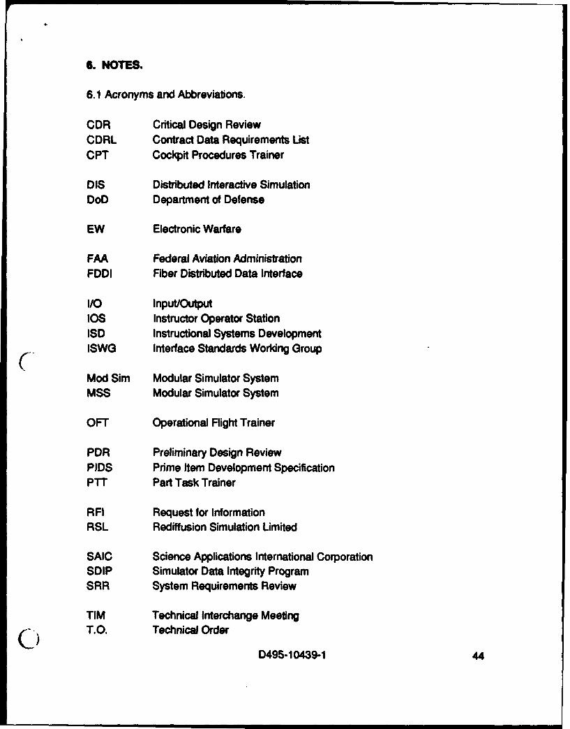
6. NOTES.
6.1 Acronyms and Abbreviations.
CDR Critical Design ReviewCDRL Contract Data Requirements ListCPT Cockpit Procedures Trainer
DIS Distributed Interactive SimulationDoD Department of Defense
EW Electronic Warfare
FAA Federal Aviation AdministrationFDDI Fiber Distributed Data Interface
I/O Input/OutputlOS Instructor Operator StationISD Instructional Systems DevelopmentISWG Interface Standards Working Group
Mod Sim Modular Simulator SystemMSS Modular Simulator System
OFT Operational Flight Trainer
PDR Preliminary Design ReviewPIDS Prime Item Development SpecificationPTT Part Task Trainer
RFI Request for InformationRSL Rediffusion Simulation Umited
SAIC Science Applications International CorporationSDIP Simulator Data Integrity ProgramSRR System Requirements Review
TIM Technical Interchange MeetingC) T.O. Technical Order
D495-10439-1 44

TRR Test Readiness ReviewTSSC Training System Support Center
UTSS Universal Threat System for Simulators
VNET Virtual Network
WST Weapon System Trainer
XTP Xpress Transfer Protocol
D
0D495- 10439-1 45

ACTIVE PAGE RECORDADDED PAGES ADDED PAGES
cc- cc I " I- Ic
PAGE NO. -' PAGE NO. ' PAGE NO. PAGE NO. I PAGE NO. PAGE NO.
1 402 - 413 - 424 435 - 44 -
6 - 45 -
7 - 46 -
8 - 47 -
91011121314151617 -
18 -
19 -
20 -
21 -
22 -23 -
24 -
25 -
26 -
27 -28 -
29 -
30 -31 -32 -
33 -
34 -
35 -
36 -
37 -
3839
______- ____ -D495-10439-1 46

REVISIONSLTR DESCRIPTION DATE APPROVAj
D 0.
-D-.I495-10439-1 47 I
,j~