Embed Size (px)
Citation preview
270 630-852-0500T-12
TorsionalLF SeriesOverview
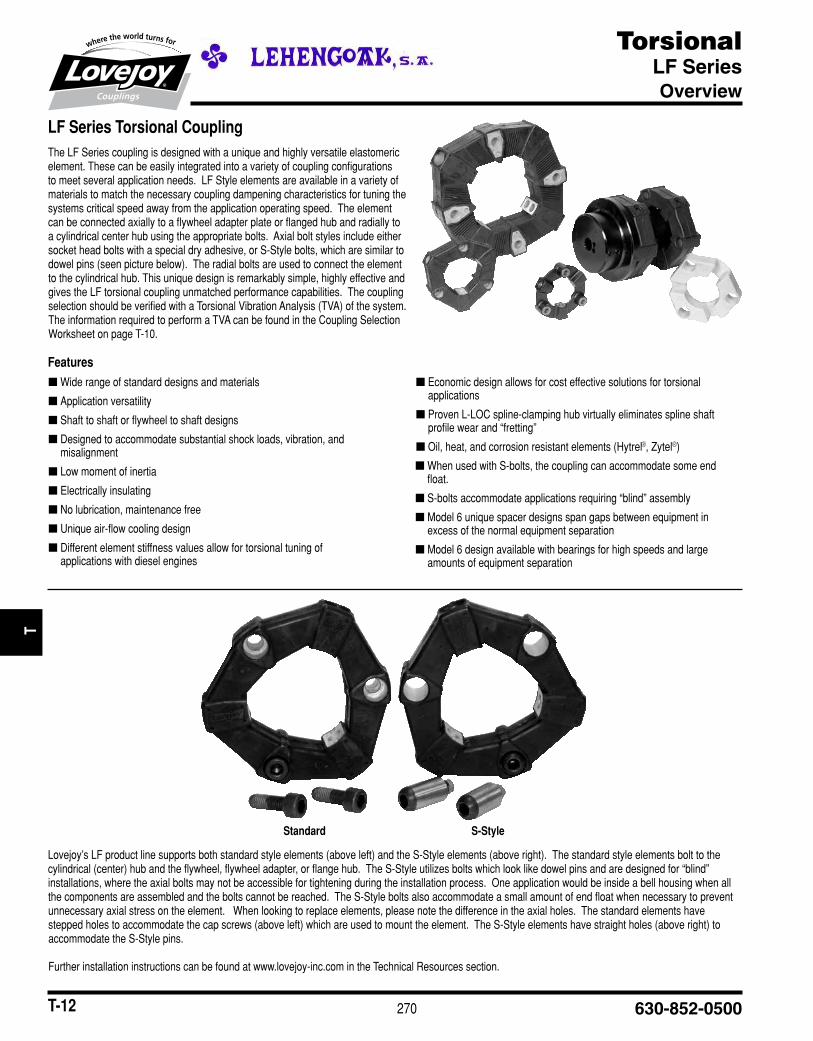
LF Series Torsional CouplingThe■LF■Series■coupling■is■designed■with■a■unique■and■highly■versatile■elastomeric■element.■These■can■be■easily■integrated■into■a■variety■of■coupling■configurations■to■meet■several■application■needs.■■LF■Style■elements■are■available■in■a■variety■of■materials■to■match■the■necessary■coupling■dampening■characteristics■for■tuning■the■systems■critical■speed■away■from■the■application■operating■speed.■■The■element■can■be■connected■axially■to■a■flywheel■adapter■plate■or■flanged■hub■and■radially■to■a■cylindrical■center■hub■using■the■appropriate■bolts.■■Axial■bolt■styles■include■either■socket■head■bolts■with■a■special■dry■adhesive,■or■S-Style■bolts,■which■are■similar■to■dowel■pins■(seen■picture■below).■■The■radial■bolts■are■used■to■connect■the■element■to■the■cylindrical■hub.■This■unique■design■is■remarkably■simple,■highly■effective■and■gives■the■LF■torsional■coupling■unmatched■performance■capabilities.■■The■coupling■selection■should■be■verified■with■a■Torsional■Vibration■Analysis■(TVA)■of■the■system.■The■information■required■to■perform■a■TVA■can■be■found■in■the■Coupling■Selection■Worksheet■on■page■T-10.
■■ Wide■range■of■standard■designs■and■materials
■■ Application■versatility
■■ Shaft■to■shaft■or■flywheel■to■shaft■designs
■■ Designed■to■accommodate■substantial■shock■loads,■vibration,■and■misalignment
■■ Low■moment■of■inertia
■■ Electrically■insulating
■■ No■lubrication,■maintenance■free
■■ Unique■air-flow■cooling■design
■■ Different■element■stiffness■values■allow■for■torsional■tuning■of■applications■with■diesel■engines
■■ Economic■design■allows■for■cost■effective■solutions■for■torsional■applications
■■ Proven■L-LOC■spline-clamping■hub■virtually■eliminates■spline■shaft■profile■wear■and■“fretting”
■■ Oil,■heat,■and■corrosion■resistant■elements■(Hytrel®,■Zytel®)
■■ When■used■with■S-bolts,■the■coupling■can■accommodate■some■end■float.
■■ S-bolts■accommodate■applications■requiring■“blind”■assembly
■■ Model■6■unique■spacer■designs■span■gaps■between■equipment■in■excess■of■the■normal■equipment■separation
■■ Model■6■design■available■with■bearings■for■high■speeds■and■large■amounts■of■equipment■separation
Features
Lovejoy’s■LF■product■line■supports■both■standard■style■elements■(above■left)■and■the■S-Style■elements■(above■right).■■The■standard■style■elements■bolt■to■the■cylindrical■(center)■hub■and■the■flywheel,■flywheel■adapter,■or■flange■hub.■■The■S-Style■utilizes■bolts■which■look■like■dowel■pins■and■are■designed■for■“blind”■installations,■where■the■axial■bolts■may■not■be■accessible■for■tightening■during■the■installation■process.■■One■application■would■be■inside■a■bell■housing■when■all■the■components■are■assembled■and■the■bolts■cannot■be■reached.■■The■S-Style■bolts■also■accommodate■a■small■amount■of■end■float■when■necessary■to■prevent■unnecessary■axial■stress■on■the■element.■■■When■looking■to■replace■elements,■please■note■the■difference■in■the■axial■holes.■■The■standard■elements■have■stepped■holes■to■accommodate■the■cap■screws■(above■left)■which■are■used■to■mount■the■element.■■The■S-Style■elements■have■straight■holes■(above■right)■to■accommodate■the■S-Style■pins.
Further■installation■instructions■can■be■found■at■www.lovejoy-inc.com■in■the■Technical■Resources■section.
Standard S-Style
JWJI
SC
JSF
MC
GH
PG
DD
TSP
UJ
VSD
RSL
DED
JWJIS
CJ
SFM
CG
HP
GD
DT
SPU
JVSD
RSLD
ED
271www.lovejoy-inc.com T-13
TorsionalLF Series – Elements
Overview
LF Series Torsional ElementsThe■focus■of■any■coupling■is■the■flexible■elements,■or■the■“working■component”.■The■element■must■effectively■absorb■the■shock■loads,■misalignment■forces,■and■torsional■vibrations,■under■a■variety■of■environmental■conditions.■The■following■materials■are■used■to■accommodate■the■different■conditions■and■environments■where■the■couplings■are■used.
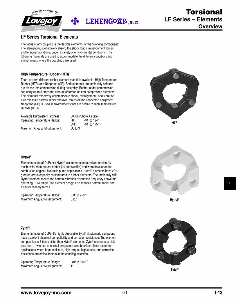
High Temperature Rubber (HTR)There■are■two■different■rubber■element■materials■available,■High■Temperature■Rubber■(HTR)■and■Neoprene■(CR).■Both■elements■are■torsionally■soft■and■are■placed■into■compression■during■assembly.■Rubber■under■compression■can■carry■up■to■5■times■the■amount■of■torque■as■non-compressed■elements.■The■elements■effectively■accommodate■shock,■misalignment,■and■vibration■plus■minimize■harmful■radial■and■axial■forces■on■the■connected■equipment.■Neoprene■(CR)■is■used■in■environments■that■are■hostile■to■High■Temperature■Rubber■(HTR).
Available■Durometer■Hardness■:■ 50,■60■(Shore■A■scale)Operating■Temperature■Range:■ HTR:■■■ -40°■to■194°■F■■■ CR:■ -40°■to■175°■FMaximum■Angular■Misalignment:■ Up■to■3°
Hytrel®
Elements■made■of■DuPont’s■Hytrel®■elastomer■compound■are■torsionally■much■stiffer■than■natural■rubber■(20■times■stiffer)■and■were■developed■for■combustion■engine■/■hydraulic■pump■applications.■Hytrel®■elements■have■20%■greater■torque■capacity■as■compared■to■rubber■elements.■The■torsionally■stiff■Hytrel®■element■moves■the■harmful■vibration■resonance■frequency■above■the■operating■RPM■range.■The■element■design■also■reduces■harmful■radial■and■axial■reactionary■forces.
Operating■Temperature■Range:■ -60°■to■250°■FMaximum■Angular■Misalignment:■ 0.25°
Zytel®
Elements■made■of■DuPont’s■highly■stressable■Zytel®■elastomeric■compound■have■excellent■chemical■compatibility■and■corrosion■resistance.■The■element■composition■is■3-times■stiffer■then■Hytrel®■elements.■Zytel®■elements■exhibit■less■than■1°■wind■up■at■normal■torque■and■zero■backlash.■Most■suited■for■applications■where■heat,■moisture,■high■torque■/■high■speed,■and■corrosion■resistance■are■critical■factors■in■the■coupling■selection.
Operating■Temperature■Range:■ -40°■to■300°■FMaximum■Angular■Misalignment:■ 1°
HTR
Hytrel®
Zytel®
JWJI
SC
JSF
MC
GH
PG
DD
TSP
UJ
VSD
RSL
DED
JWJIS
CJ
SFM
CG
HP
GD
DT
SPU
JVSD
RSLD
ED

272 630-852-0500T-14
TorsionalLF Series – Base Element, Models 1, 1/S, 2 and 2/S
Selection Data
The■following■are■standard■LF■Series■torsional■coupling■models.■The■simple,■unique■design■permits■a■wide■range■of■models■from■common■components■to■meet■each■application■requirement.■
Base ElementThe■heart■of■the■LF■Series■coupling■is■the■flexible■base■element.■This■element■allows■the■customer■to■make■their■own■shaft■hubs■from■steel■bar■stock■or■use■existing■hubs.■Ideal■for■quick■prototype■testing,■retrofit■and■high■volume■applications.■■
Model 1 and 1/SConsists■of■the■flexible■base■element■with■a■simple■steel■cylindrical■hub.■
The■1/S■is■shown■with■the■S-Style■axial■screw■(similar■to■a■dowel)■for■quick■blind■assembly■of■the■drive■package.■The■same■combinations■available■in■Model■1■are■also■available■in■the■Model■1/S.
■
Model 2 and 2/SProvides■a■complete■shaft-to-shaft■coupling■in■a■range■of■sizes■for■all■industrial■power■transmission■applications.■It■is■similar■to■Model■1■shown■above,■except■a■flanged■hub■is■added■to■make■the■shaft■to■shaft■connection.
Model■2/S■allows■the■drive■package■to■be■“blind”■connected.■As■with■all■S-Style■models,■axial■end■float■of■equipment■shafts■can■be■accommodated■without■harmful■push-pull■force.
Standard Base Element
Model 1
Model 2
S-Style Base Element
Model 1/S
Model 2/S
JWJI
SC
JSF
MC
GH
PG
DD
TSP
UJ
VSD
RSL
DED
JWJIS
CJ
SFM
CG
HP
GD
DT
SPU
JVSD
RSLD
ED
273www.lovejoy-inc.com T-15
TorsionalLF Series – Models 3, 3/S, 6, 6/S and 6B
Selection Data
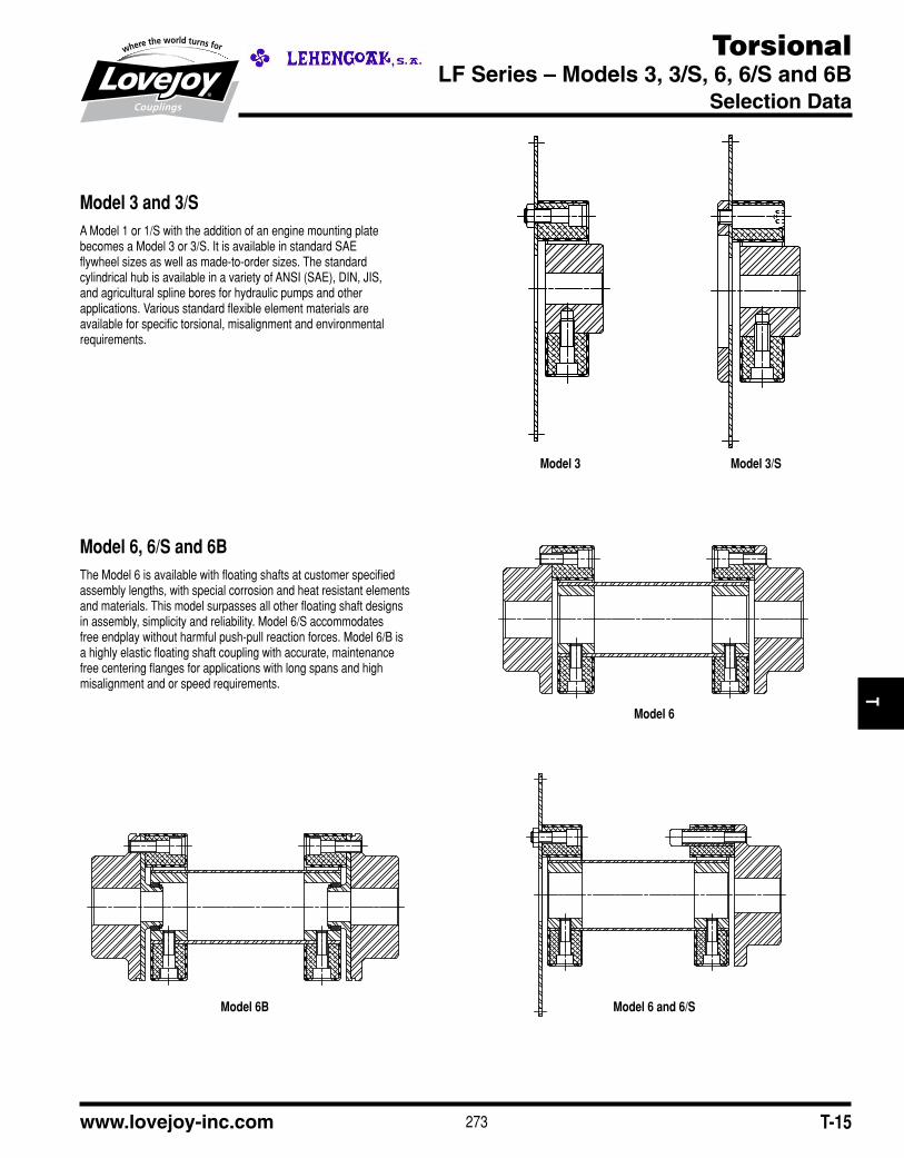
Model 3 and 3/SA■Model■1■or■1/S■with■the■addition■of■an■engine■mounting■plate■becomes■a■Model■3■or■3/S.■It■is■available■in■standard■SAE■flywheel■sizes■as■well■as■made-to-order■sizes.■The■standard■cylindrical■hub■is■available■in■a■variety■of■ANSI■(SAE),■DIN,■JIS,■and■agricultural■spline■bores■for■hydraulic■pumps■and■other■applications.■Various■standard■flexible■element■materials■are■available■for■specific■torsional,■misalignment■and■environmental■requirements.
Model 6, 6/S and 6BThe■Model■6■is■available■with■floating■shafts■at■customer■specified■assembly■lengths,■with■special■corrosion■and■heat■resistant■elements■and■materials.■This■model■surpasses■all■other■floating■shaft■designs■in■assembly,■simplicity■and■reliability.■Model■6/S■accommodates■free■endplay■without■harmful■push-pull■reaction■forces.■Model■6/B■is■a■highly■elastic■floating■shaft■coupling■with■accurate,■maintenance■free■centering■flanges■for■applications■with■long■spans■and■high■misalignment■and■or■speed■requirements.
Model 3 Model 3/S
Model 6
Model 6B Model 6 and 6/S
JWJI
SC
JSF
MC
GH
PG
DD
TSP
UJ
VSD
RSL
DED
JWJIS
CJ
SFM
CG
HP
GD
DT
SPU
JVSD
RSLD
ED

274 630-852-0500T-16
TorsionalLF Series
Performance Data
LF Series Performance Data
Element Nominal Maximum Max Allowable Dynamic Torsional Stiffness CTdyn
Material Torque Torque Speed Continuous Rubber 60 Shore Rubber 50 Shore Hytrel® 1 Zytel®
TKN TKmax Nmax Vibratory Trq (Standard) (Optional)
TKW
Size in-lb Nm in-lb Nm RPM in-lb Nm in-lb/rad Nm/rad in-lb/rad Nm/rad in-lb/rad Nm/rad in-lb/rad Nm/rad
LF1 HTR ■90■ ■10 ■200■ ■25 10,000 44 ■5 ■1,240■ ■140 ■800■ ■90 — — — —
LF2HTR ■180■ ■20 ■530■ ■60 8,000 89 ■10 ■2,570■ ■290 ■1,600■ ■180 — — — —
Zytel® ■265■ ■30 ■530■ ■60 10,000 N/A N/A — — — — — — ■55,150■ 6■230
LF4 HTR ■440■ ■50 ■1,100■ ■125 7,000 180 ■20 ■7,500■ ■850 ■4,870■ ■550 — — — —
LF8HTR ■885■ ■100 ■2,480■ ■280 6,500 355 ■40 ■13,300■ 1■500 ■7,970■ ■900 — — — —
Zytel® ■1,060■ ■120 ■2,480■ ■280 7,000 N/A N/A — — — — — — ■414,370■ 46■820
LF12 HTR ■1,240■ ■140 ■3,190■ ■360 6,500 440 ■50 ■38,900■ 4■400 ■23,900■ 2■700 — — — —
LF16
HTR ■1,770■ ■200 ■4,960■ ■560 6,000 710 ■80 ■30,100■ 3■400 ■17,700■ 2■000 — — — —
Hytrel® ■1,770■ ■200 ■4,960■ ■560 5,500 N/A N/A — — — — ■320,000 36■000 — —
Zytel® ■2,120■ ■240 ■4,960■ ■560 6,000 N/A N/A — — — — — — ■654,800■ 74■000
LF22 HTR ■2,430■ ■275 ■6,640■ ■750 6,000 885 ■100 ■79,600■ 9■000 ■54,000■ 6■100 — — — —
LF25 HTR ■2,790■ ■315 ■7,740■ ■875 5,000 1,100 ■125 ■39,800■ 4■500 ■4,800■ 2■800 — — — —
LF28 HTR ■3,700 ■420 ■10,600■ 1■200 5,000 1,330 ■150 ■106,200■ 12■000 ■66,400■ 7■500 — — — —
LF30HTR ■4,400■ ■500 ■12,400■ 1■400 4,000 1,770 ■200 ■69,000■ 7■800 ■42,500■ 4■800 — — — —
Hytrel® ■4,400■ ■500 ■12,400■ 1■400 4,000 N/A N/A — — — — ■780,000 88■000 — —
LF50HTR ■6,200■ ■700 ■18,600■ 2■100 4,000 2,650 ■300 ■168,100■ 19■000 ■106,200■ 12■000 — — — —
Hytrel® ■7,100■ ■800 ■17,700■ 2■000 4,000 N/A N/A — — — — 2,300,000 262■000 — —
LF80 HTR ■7,960■ ■900 ■18,600■ 2■100 4,000 2,830 ■320 ■221,200■ 25■000 ■141,600■ 16■000 — — — —
LF90 HTR ■9,700■ 1■100 ■27,900■ 3■150 3,600 3,980 ■450 ■141,600■ 16■000 ■92,900■ 10■500 — — — —
LF140 HTR ■15,000■ 1■700 ■43,400■ 4■900 3,600 6,200 ■700 ■354,000■ 40■000 ■234,500■ 26■500 — — — —
LF250 HTR ■26,500■ 3■000 ■77,400■ 8■750 3,000 11,000 1■250 ■592,900■ 67■000 ■380,500■ 43■000 — — — —
Notes:■■ n■■1■indicates:■For■Hytrel,■dynamic■torsional■stiffness■values■are■non-linear■with■respect■to■torque.■■Value■given■is■for■100%■of■nominal■torque.■■ n■■■N/A■indicates:■Not■Applicable.■ n■■■HTR■is■High■Temperature■Rubber.
JWJI
SC
JSF
MC
GH
PG
DD
TSP
UJ
VSD
RSL
DED
JWJIS
CJ
SFM
CG
HP
GD
DT
SPU
JVSD
RSLD
ED

275www.lovejoy-inc.com T-17
TorsionalLF Series
Performance Data
Notes:■■ n■■■*■indicates:■Angular■and■parallel■misalignment■values■are■dependent■on■speed,■and■for■rubber■elements,■should■be■adjusted■according■to■figure■4■on■page■T-9.■Hytrel®■elements■are■only■for■applications■where■the■driven■component■is■piloted■to■the■driver■for■SAE■and■DIN■established■alignments■(i.e.■Hydraulic■pump■flange-mounted■to■engine■flywheel■housing).
■ n■■■**■■indicates:■The■“S-Style”■design■is■not■constrained■axially■and■allows■the■hubs■to■move■apart■without■creating■axial■force■on■the■connected■equipment.
■ n■■■N/A■indicates:■Not■Applicable.■ n■■■Hytrel®■elements■are■only■for■applications■where■the■driven■component■is■piloted■to■the■driver■for■essentially■perfect■alignment■(hydraulic■pump■
flange-mounted■to■engine■housing).■ n■■■Special■length■S-Style■fastener■sleeves■can■further■increase■the■allowable■end■float.■ n■■■HTR■is■High■Temperature■Rubber.
LF Series Performance Data Continued
Element Max Allowable Misalignment* Wind Up Static Stiffness
Material Angular Parellel Axial (End Float) Axial (End Float) (angle of twist) Axial Ca Radial Cr Angular Cw
∆Kw ∆Kr Standard S-Style** at at
∆Ka Nominal Maximum
Torque Torque
Size Degrees in mm in mm in mm Degrees Degrees lb/in N/mm lb/in N/mm in-lb/deg Nm/deg
LF1 HTR 3.00 0.060 1.5 +/-0.08 +/-2 +0.18■/■-0.08 +4.6■/■-2 6 17.0 ■220■ ■38 ■860■ ■150 2.66 0.3
LF2HTR 3.00 0.060 1.5 +/-0.12 +/-3 +0.12■/■-0.12 +3■/■-3 6 17.0 ■130■ ■22 ■860■ ■150 2.66 0.3
Zytel® 1.00 0.004 0.1 +/-0.02 +/-0.5 +0.12■/■-0.02 +3■/■-0.5 — — — — — — — —
LF4 HTR 3.00 0.060 1.5 +/-0.12 +/-3 +0.17■/■-0.12 +4.3■/■-3 5 ■12.0 ■430■ ■75 ■2,860■ ■500 21.30 2.4
LF8HTR 3.00 0.080 2.0 +/-0.16 +/-4 +0.20■/■-0.16 +5■/■-4 5 14.0 ■430■ ■75 ■2,860■ ■500 31.90 3.6
Zytel® 1.00 0.004 0.1 +/-0.02 +/-0.5 +0.20■/-0.02 +5■/■-0.5 — — — — — — — —
LF12 HTR 2.00 0.080 2.0 +/-0.12 +/-3 +0.20■/-0.16 +5■/■-4 3 7.5 ■1,430■ ■250 ■5,710■ 1■000 80.00 9.0
LF16
HTR 3.00 0.080 2.0 +/-0.20 +/-5 +0.23■/■-0.20 +5.8■/■-5 5 14.0 ■570■ ■100 ■2,860■ ■500 44.00 5.0
Hytrel® 0.25 0.000 0.0 +0.12■/■-0.08 +3■/■-2 N/A N/A — — — — — — — —
Zytel® 1.00 0.004 0.1 +/-0.02 +/-0.5 +0.23■/-0.02 +5.8■/■-0.5 — — — — — — — —
LF22 HTR 2.00 0.080 2.0 +/-0.12 +/-3 +0.23■/-0.20 +5.8■/■-5 3 7.5 ■2,860■ ■500 ■7,420■ 1■300 106.00 12.0
LF25 HTR 3.00 0.080 2.0 +/-0.20 +/-5 +0.26■/■-0.20 +6.6■/■-5 5 14.0 ■800■ ■140 ■3,400■ ■600 62.00 7.0
LF28 HTR 2.00 0.080 2.0 +/-0.12 +/-3 +0.26■/■-0.20 +6.6■/■-5 3 7.5 ■3,140■ ■550 ■8,000■ 1■400 150.00 17.0
LF30HTR 3.00 0.080 2.0 +/-0.20 +/-5 +0.26■/■-0.20 +6.6■/■-5 5 14.0 ■1,090■ ■190 ■4,280■ ■750 80.00 9.0
Hytrel® 0.25 0.000 0.0 +0.12■/■-0.08 +3■/■-2 N/A N/A — — — — — — — —
LF50HTR 3.00 0.080 2.0 +/-0.20 +/-5 +0.26■/■-0.20 +6.6■/■-5 3 7.5 ■3,700■ ■650 ■12,600■ 2■200 230.00 26.0
Hytrel® 0.25 0.000 0.0 +0.12■/■-0.08 +3■/■-2 N/A N/A — — — — — — — —
LF80 HTR 2.00 0.060 1.5 +/-0.20 +/-5 +0.26■/■-0.12 +6.6■/■-3 3 7.5 ■4,850■ ■850 ■16,600■ 2■900 300.00 34.0
LF90 HTR 3.00 0.080 2.0 +/-0.20 +/-5 +0.34■/■-0.20 +8.6■/■-5 5 14.0 ■1,260■ ■220 ■5,700■ 1■000 150.00 17.0■
LF140 HTR 2.00 0.080 2.0 +/-0.20 +/-5 +0.34■/■-0.20 +8.6■/■-5 3 7.5 ■3,700■ ■650 ■13,100■ 2■300 336.00 38.0
LF250 HTR 2.00 0.080 2.0 +/-0.20 +/-5 +0.40■/■-0.20 +10■/■-5 3 7.5 ■6,570■ 1■150 ■23,400■ 4■100 600.00 68.0
JWJI
SC
JSF
MC
GH
PG
DD
TSP
UJ
VSD
RSL
DED
JWJIS
CJ
SFM
CG
HP
GD
DT
SPU
JVSD
RSLD
ED

276 630-852-0500T-18
TorsionalLF Series – Base Element and Model 1
Dimensional Data
Base Element (HTR)
Model 1 (HTR)
Base Element (Hytrel®)
Model 1 (Hytrel®)
Base Element (Zytrel®)
Model 1 (Zytel®)
Note:■■ n■■HTR■is■High■Temperature■Rubber.
JWJI
SC
JSF
MC
GH
PG
DD
TSP
UJ
VSD
RSL
DED
JWJIS
CJ
SFM
CG
HP
GD
DT
SPU
JVSD
RSLD
ED
LF Series Base Element and Model 1 Dimensional Data
ID 1 ID 2 OD FOD ET OAL L
(Cylindrical Hub) (Flange Hub) HTR Hytrel® Zytel® HTR Hytrel® Zytel® HTR Hytrel® Zytel®
Min Bore Max Bore Min Bore Max Bore
Size in mm in mm in mm in mm in mm in mm in mm in mm in mm in mm in mm in mm in mm in mm in mm
LF1 0.31 8 0.63 19 0.31 8 0.88 25 2.20 56 — — — — 2.20 56 0.94 24 — — — — 1.97 50.0 1.02 26 — — — —
LF2 0.44 10 0.88 26 0.50 12 1.38 38 3.35 85 — — 3.48 32 3.35 85 0.94 24 — — 0.94 32 2.36 60.0 1.26 32 — — 1.26 32.0
LF4 0.47 12 1.00 30 0.63 15 1.75 45 3.94 100 — — — — 3.94 100 1.10 28 — — — — 2.52 64.0 1.34 34 — — — —
LF8 0.50 12 1.38 38 0.75 18 2.00 55 4.72 120 — — 4.92 45 4.72 120 1.26 32 — — 1.18 45 3.46 88.0 1.81 46 — — 1.77 45.0
LF12 0.50 12 1.38 38 0.75 18 2.00 55 4.80 122 — — — — 4.72 120 1.26 32 — — — — 3.46 88.0 1.81 46 — — — —
LF16 0.63 15 1.63 48 0.81 20 2.63 70 5.91 150 6.10 155 6.10 53 5.91 150 1.65 42 1.69 58 1.38 53 4.17 106.0 2.20 56 2.28 58 2.08 53.0
LF22 0.63 15 1.63 48 0.81 20 2.63 70 5.91 150 — — — — 5.91 150 1.65 42 — — — — 4.17 106.0 2.20 56 — — — —
LF25 0.63 15 2.13 55 0.81 20 2.75 85 6.69 170 7.17 182 — — 6.69 170 1.81 46 1.85 62 — — 4.57 116.0 2.40 61 2.44 62 — —
LF28 0.63 15 2.13 55 0.81 20 2.75 85 6.69 170 — — — — 6.69 170 1.81 46 — — — — 4.57 116.0 2.40 61 — — — —
LF30 0.81 20 2.44 65 1.00 25 3.75 100 7.87 200 8.07 205 — — 7.87 200 2.28 56 2.28 76 — — 5.51 140.0 2.91 74 2.99 76 — —
LF50 0.81 20 2.44 65 1.00 25 3.75 100 7.87 200 8.07 205 — — 7.87 200 2.28 56 2.28 76 — — 5.51 140.0 2.91 74 2.99 76 — —
LF80 0.81 20 2.44 65 1.00 25 3.75 100 8.07 205 — — — — 7.87 200 2.56 65 — — — — 5.51 141.5 2.97 76 — — — —
LF90 1.19 30 3.35 85 1.19 30 4.25 110 10.24 260 — — — — 10.24 260 2.76 70 — — — — 6.61 168.0 3.46 88 — — — —
LF140 1.19 30 3.35 85 1.19 30 4.25 110 10.24 260 — — — — 10.24 260 2.76 70 — — — — 6.61 168.0 3.46 88 — — — —
LF250 1.63 40 4.25 105 1.63 40 5.00 130 13.38 340 — — — — 13.38 340 3.34 84 — — — — 8.18 208.0 4.25 108 — — — —

277www.lovejoy-inc.com T-19
TorsionalLF Series – Models 1/S, 2 and 2/S
Dimensional Data
Model 1S (HTR) Model 2 (HTR)
Model 2 (Hytrel®)Model 2/S (HTR) Model 2 (Zytel®)
LF Series Base Element and Model 1 Dimensional Data ContinuedLTB HD FD FW BE S* ER** R BC T TS TL
(+/-0.11) (+/-3) Axial HTR Zytel®
Hole
and
Size in mm in mm in mm in mm in mm in mm in mm in mm in mm Division in mm in mm in mm
LF1 0.94 24 1.18 30 1.44 36 0.27 7 0.08 2 — — 0.87 22 0.43 11.0 1.73 44 2@180° ■■M6 0.39 10 — — 0.28 7
LF2 1.10 28 1.57 40 2.17 55 0.31 8 0.16 4 — — 0.79 20 0.39 10.0 2.68 68 2@180° ■■M8 0.55 14 0.59 15 0.31 8
LF4 1.18 30 1.77 45 2.56 65 0.31 8 0.16 4 — — 0.94 24 0.47 12.0 3.15 80 3@120° ■■M8 0.55 14 — — 0.31 8
LF8 1.65 42 2.36 60 3.15 80 0.39 10 0.16 4 — — 1.10 28 0.55 14.0 3.94 100 3@120° M10 0.67 17 0.75 19 0.39 10
LF12 1.65 42 2.36 60 3.15 80 0.39 10 0.16 4 — — 1.10 28 0.55 14.0 3.94 100 4@■■90° M11 0.67 17 — — 0.39 10
LF16 1.97 50 2.76 70 3.94 100 0.47 12 0.24 6 1.02 26 1.42 36 0.71 18.0 4.92 125 3@120° M12 0.75 19 0.86 22 0.47 12
LF22 1.97 50 2.76 70 3.94 100 0.47 12 0.24 6 — — 1.42 36 0.71 18.0 4.92 125 4@■■90° M12 0.75 19 — — 0.47 12
LF25 2.16 55 3.35 85 4.53 115 0.55 14 0.24 6 1.06 27 1.57 40 0.79 20.0 5.51 140 3@120° M14 0.86 22 — — 0.55 14
LF28 2.16 55 3.35 85 4.53 115 0.55 14 0.24 6 — — 1.57 40 0.79 20.0 5.51 140 4@■■90° M14 0.86 22 — — 0.55 14
LF30 2.60 66 3.94 100 5.51 140 0.63 16 0.31 8 1.38 35 1.97 50 0.98 25.0 6.50 165 3@120° M16 0.98 25 — — 0.63 16
LF50 2.60 66 3.94 100 5.51 140 0.63 16 0.31 8 1.38 35 1.99 50 0.98 25.0 6.50 165 4@■■90° M16 0.98 25 — — 0.63 16
LF80 2.60 66 3.94 100 5.51 140 0.63 16 0.31 8 — — 2.40 61 1.20 30.5 6.50 165 4@■■90° M16 0.98 25 — — 0.63 16
LF90 3.15 80 4.92 125 6.30 160 0.75 19 0.31 8 — — 2.44 62 1.22 31.0 8.46 215 3@120° M20 1.26 32 — — 0.79 20
LF140 3.15 80 4.92 125 6.30 160 0.75 19 0.31 8 — — 2.44 62 1.22 31.0 8.46 215 4@■■90° M20 1.26 32 — — 0.79 20
LF250 3.94 100 6.30 160 7.68 195 0.75 19 0.31 8 — — 3.03 77 0.89 22.5 11.02 280 4@■■90° M20 1.26 32 — — 0.79 20
Notes:■■ n■■■*■indicates:■Dimenstion■S■for■Hytrel®■only.■ n■■■**■indicates:■Dimension■ER■for■HTR■(rubber)■only.■ n■■■■Dimensions■for■basic■Models■1,■2,■3■and■6.■ n■■HTR■is■High■Temperature■Rubber.
JWJI
SC
JSF
MC
GH
PG
DD
TSP
UJ
VSD
RSL
DED
JWJIS
CJ
SFM
CG
HP
GD
DT
SPU
JVSD
RSLD
ED

278 630-852-0500T-20
TorsionalLF Series – Models 3 and 3/S
Dimensional Data
Notes:■■ n■■■*■indicates:■Dimension■ER■for■HTR■(rubber)■only.■ n■■■HTR■is■High■Temperature■Rubber.
Model 3 (HTR) Model 3/S (HTR)
Model 3 and 3/S (Zytel®)Model 3 (Hytrel®)
LF Series Flywheel Models 3 and 3/S Dimensional Data
ID OD ET TL L W
Min Max HTR Hytrel® Zytel® HTR Hytrel® Zytel® HTR Hytrel® Zytel®
Size in mm in mm in mm in mm in mm in mm in mm in mm in mm in mm in mm in mm in mm
LF1 0.31 8 0.63 19 2.20 56 — — — — 0.94 24 — — — — 0.28 7 1.02 26.0 — — — — — —
LF2 0.44 10 0.88 26 3.35 85 — — 3.48 88 0.94 24 — — 0.94 24 0.31 8 1.26 32.0 — — 1.26 32 — —
LF4 0.47 12 1.00 30 3.94 100 — — — — 1.10 28 — — — — 0.31 8 1.34 34.0 — — — — — —
LF8 0.50 12 1.38 38 4.72 120 — — 4.92 125 1.26 32 — — 1.18 30 0.39 10 1.81 46.0 — — 1.77 45 0.19 5
LF12 0.50 12 1.38 38 4.80 122 — — — — 1.26 32 — — — — 0.39 10 1.81 46.0 — — — — 0.19 5
LF16 0.63 15 1.63 48 5.91 150 6.10 155 6.10 155 1.65 42 1.69 43 1.38 36 0.47 12 2.20 56.0 2.28 58 2.08 53 0.19 5
LF22 0.63 15 1.63 48 5.91 150 — — — — 1.65 42 — — — — 0.47 12 2.20 56.0 — — — — 0.19 5
LF25 0.63 15 2.13 55 6.69 170 — — — — 1.81 46 — — — — 0.55 14 2.40 61.0 — — — — 0.19 5
LF28 0.63 15 2.13 55 6.69 170 — — — — 1.81 46 — — — — 0.55 14 2.40 61.0 — — — — 0.19 5
LF30 0.81 20 2.44 65 7.87 200 8.07 205 — — 2.28 58 2.28 58 — — 0.63 16 2.91 74.0 2.99 76 — — 0.19 5
LF50 0.81 20 2.44 65 7.87 200 8.07 250 — — 2.28 58 2.28 58 — — 0.46 12 2.91 74.0 2.99 76 — — 0.19 5
LF80 0.81 20 2.44 65 8.07 205 — — — — 2.56 65 — — — — 0.63 16 2.97 75.5 — — — — 0.19 5
LF90 1.19 30 3.35 85 10.24 260 — — — — 2.76 70 — — — — 0.79 20 3.46 88.0 — — — — 0.19 5
LF140 1.19 30 3.35 85 10.24 260 — — — — 2.76 70 — — — — 0.79 20 3.46 88.0 — — — — 0.19 5
LF250 1.63 40 4.25 105 13.38 340 — — — — 3.34 85 — — — — 0.79 20 4.25 108.0 — — — — 0.50 13
JWJI
SC
JSF
MC
GH
PG
DD
TSP
UJ
VSD
RSL
DED
JWJIS
CJ
SFM
CG
HP
GD
DT
SPU
JVSD
RSLD
ED

279www.lovejoy-inc.com T-21
TorsionalLF Series – Models 3, 3/S and Flywheel Housings
Dimensional Data
Typical Flywheel Housing Combinations
SAE LF Series LK Series SAE J617C Flywheel HousingJ620D
FlywheelSize Size Size 6 5 4 3 2 1
6.5 8■thru■28 100 s s
7.5 8■thru■28 100 l l
8 8■thru■30 100 s
10 8■thru■140 100,■125 l s s
11.5 16■thru■140 100,■125,■150,■150D l l s
14 28■thru■250 150,■UNIV l
18 250 UNIV l
Notes:■■ s■indicates:■Preferred■combinations.■ l ■indicates:■Optional■sizes■available.
Notes:■■ n■■■*■indicates:■Hytrel®■only.■ n■■HTR■is■High■Temperature■Rubber.
Notes:■■ n■■■SAE■J620■Flywheel■dimensions.■ n■■N/A■indicates:■Not■Applicable.■ n■■HTR■is■High■Temperature■Rubber.
LF Series Flywheel Models 3/S Dimensional Data
P FBC
SAE Pilot Bolt Circle Thru Holes LF Coupling Size for SAE
Flywheel Diameter Diameter Nominal Flywheel Sizes
HTR Hytrel® Zytel®
Size in mm in mm Qty Dia Model 3 & 3/S Model 3 Model 3
6.5 8.499 215.90 7.875 200.02 6 0.31 8,■16 8,■16 8,■16
7.5 9.499 241.30 8.750 222.25 8 0.31 8,■16 8,■16 8,■16
8 10.374 263.52 9.625 244.47 6 0.41 16,■25 6,■30 16,■25,■30
10 12.374 314.32 11.625 295.27 8 0.41 25,■30,■50,■90 30,■50 25,■30
11.5 13.874 352.42 13.125 333.37 8 0.41 30,■50,■90,■140,■250 50,■140,■250 30
14 18.374 466.72 17.250 438.15 8 0.53 90,■140,■250 140 N/A
16 20.374 517.50 19.250 488.95 8 0.53 250 250 N/A
LF Series Flywheel Models 3 and 3/S Dimensional Data Continued
LTB BE S* ER* R HD BC T TS(±0.11) (+/-3) Axial HTR Zytel®
Holeand
Size in mm in mm in mm in mm in mm in mm in mm Division in mm in mmLF1 0.94 24 0.08 2 — — 0.87 22 0.43 11.0 1.18 30 1.73 44 2@180° M6 0.39 10 — —LF2 1.10 28 0.16 4 — — 0.79 20 0.39 10.0 1.57 40 2.68 68 2@180° M8 0.55 14 0.59 15LF4 1.18 30 0.16 4 — — 0.94 24 0.47 12.0 1.77 45 3.15 80 3@120° M8 0.55 14 — —LF8 1.65 42 0.16 4 — — 1.10 28 0.55 14.0 2.36 60 3.94 100 3@120° M10 0.67 17 0.75 19LF12 1.65 42 0.16 4 — — 1.10 28 0.55 14.0 2.36 60 3.94 100 4@■■90° M11 0.67 17 — —LF16 1.97 50 0.24 6 1.02 26 1.42 36 0.71 18.0 2.76 70 4.92 125 3@120° M12 0.75 19 0.86 22LF22 1.97 50 0.24 6 — — 1.42 36 0.71 18.0 2.76 70 4.92 125 4@■■90° M12 0.75 19 — —LF25 2.16 55 0.24 6 1.06 27 1.57 40 0.79 20.0 3.35 85 5.51 140 3@120° M14 0.86 22 — —LF28 2.16 55 0.24 6 — — 1.57 40 0.79 20.0 3.35 85 5.51 140 4@■■90° M14 0.86 22 — —LF30 2.60 66 0.31 8 1.38 35 1.97 50 0.98 25.0 3.94 100 6.50 165 3@120° M16 0.98 25 — —LF50 2.60 66 0.31 8 1.38 35 1.97 50 0.98 25.0 3.94 100 6.50 165 4@■■90° M16 0.98 25 — —LF80 2.60 66 0.16 4 — — 2.40 61 1.20 30.5 3.94 100 6.50 165 4@■■90° M16 0.98 25 — —LF90 3.15 80 0.31 8 — — 2.44 62 1.22 31.0 4.92 125 8.46 215 3@120° M20 1.26 32 — —LF140 3.15 80 0.31 8 — — 2.44 62 1.22 31.0 4.92 125 8.46 215 4@■■90° M20 1.26 32 — —
LF250 3.94 100 0.31 8 — — 3.03 770.89 22.5
6.30 160 11.02 280 4@■■90° M20 1.26 32 — —2.15 54.5
JWJI
SC
JSF
MC
GH
PG
DD
TSP
UJ
VSD
RSL
DED
JWJIS
CJ
SFM
CG
HP
GD
DT
SPU
JVSD
RSLD
ED

280 630-852-0500T-22
TorsionalLF Series – Models 6, 6/S and 6B
Selection Process
Model 6 (HTR)
Model 6 (Zytel®)
Model 6 and 6/S (HTR)
Model 6B (HTR)
Model 6 and 6/S (Rubber Base Elements HTR and CR)This■model■compensates■for■considerable■axial,■radial■and■angular■misalignment.■■The■rubber■elements■torsionally■soft.■■Lengths■are■made■to■customer■requirements.■■S-Style■axial■mounting■screws■allow■the■hubs■to■have■free■end■float■without■exerting■axial■loads■on■the■connected■equipment,■while■allowing■for■quick■assembly.
Model 6 and 6/S (Zytel® Elements)Elements■made■of■DuPont’s■super-tough,■corrosion■resistant■Zytel®■are■torsionally■stiff■without■backlash,■with■less■than■1°■windup.■■Large■spans,■equal■to■all-metal■couplings,■can■be■accommodated■without■internal■support■bearings■when■lightweight■Zytel®■are■used.■■Hubs,■hardware■and■tubes■are■available■in■stainless■steel■or■with■plating■and■corrosion■resistant■coatings.■■S-Style,■axial■mounting■screws■allow■for■free■end-float■without■harmful■reactionary■forces.
Model 6B (HTR Elements)Similar■to■Model■6■except■the■center■shaft■is■supported■by■internal■maintenance■free■bearing■material.■■This■allows■greater■equipment■separation■and■high■speeds,■as■well■as■high■angular■misalignment,■which■can■be■obtained■with■rubber■elements.
The■drawing■at■the■lower■left■shows■one■of■the■many■special■designs■available.■■A■standard■flywheel■adapter■plate■(see■model■3)■is■used■to■couple■to■a■diesel■engine■flywheel.■■The■flanged■hub■on■the■other■end■is■supplied■with■extra■long■S-Style■connecting■screws■(Notice■the■element■is■reversed■from■its■normal■direction).■■This■arrangement■permits■extensive■axial■movement■(free■end■float)■of■the■drive■package.
One■of■the■many■features■of■the■Model■6■is■the■center■floating■shaft■can■be■radially■removed■without■displacing■the■coupled■machines.■■Flexible■elements■may■be■pre-assembled■to■the■center■segment■and■then■final■assembled■to■the■hubs■quickly,■with■little■hardware.
JWJI
SC
JSF
MC
GH
PG
DD
TSP
UJ
VSD
RSL
DED
JWJIS
CJ
SFM
CG
HP
GD
DT
SPU
JVSD
RSLD
ED

281www.lovejoy-inc.com T-23
TorsionalLF Series – Models 6, 6/S and 6B
Dimensional Data
LF Series Models 6, 6/S and 6/B Dimensional Data
ID1 - ID2 OD BC
Nominal Torque Min Bore Max Bore Element Axial
HTR Zytel® HTR Zytel® Hole
and
Size in-lb Nm in-lb Nm in mm in mm in mm in mm in mm Division
LF1 90 ■10 — — 0.31 8 0.88 25 2.20 56 — — 1.73 44 2@180°LF2 180 ■20 265 30 0.50 12 1.38 38 3.35 85 3.48 88 2.68 68 2@180°LF4 440 ■50 — — 0.63 15 1.75 45 3.94 100 — — 3.15 80 3@120°LF8 885 ■100 1,060 120 0.75 18 2.00 55 4.72 120 4.92 125 3.94 100 3@120°LF12 1,240 ■140 — — 0.75 18 2.00 55 4.80 122 — — 3.94 100 4@■■90°LF16 1,770 ■200 2,120 240 0.81 20 2.63 70 5.91 150 6.1 155 4.92 125 3@120°LF22 2,430 ■275 — — 0.81 20 2.63 70 5.91 150 — — 4.92 125 4@■■90°LF25 2,790 ■315 — — 0.81 20 2.75 85 6.69 170 — — 5.51 140 3@120°LF28 3,700 ■420 — — 0.81 20 2.75 85 6.69 170 — — 5.51 140 4@■■90°LF30 4,425 ■500 — — 1.00 25 3.75 100 7.87 200 — — 6.50 165 3@120°LF50 6,195 ■700 — — 1.00 25 3.75 100 7.87 200 — — 6.50 165 4@■■90°LF80 7,960 ■900 — — 1.00 25 3.75 100 8.07 205 — — 6.50 165 4@■■90°LF90 9,735 1■100 — — 1.19 30 4.25 110 10.24 260 — — 8.46 215 3@120°LF140 15,000 1■700 — — 1.19 30 4.25 110 10.24 260 — — 8.46 215 4@■■90°LF250 26,500 3■000 — — 1.63 40 5.00 130 13.38 340 — — 11.02 280 4@■■90°
Note:■■ n■■■Refer■to■Speed■and■Length■Performance■Data■table■(page■T-24)■for■maximum■and■minimum■values.
LF Series Models 6, 6/S and 6/B Dimensional Data Continued
FOD LTB BSE S PT FW TD ET
Flange Hub Span HTR Zytel®
Size in mm in mm in mm in mm in mm in mm in mm in mm
LF1 2.20 56 0.94 24 * 0.51 13 0.20 5 0.28 7 1.18 30 0.94 24 — —
LF2 3.35 85 1.10 28 * 0.55 14 0.20 5 0.31 8 1.62 40 0.94 24 0.94 24
LF4 3.94 100 1.18 30 * 0.63 16 0.20 5 0.31 8 1.81 45 1.10 28 — —
LF8 4.72 120 1.65 42 * 0.71 18 0.20 5 0.39 10 2.38 60 1.26 32 1.18 30
LF12 4.80 120 1.65 42 * 0.71 18 0.20 5 0.39 10 2.38 60 1.26 32 — —
LF16 5.91 150 1.97 50 * 0.94 24 0.20 5 0.47 12 2.75 70 1.65 42 1.38 36
LF22 5.91 150 1.97 50 * 0.94 24 0.20 5 0.47 12 2.75 70 1.65 42 — —
LF25 6.69 170 2.16 55 * 1.02 26 0.20 5 0.55 14 3.38 85 1.81 46 — —
LF28 6.69 170 2.16 55 * 1.02 26 0.20 5 0.55 14 3.38 85 1.81 46 — —
LF30 7.87 200 2.60 66 * 1.30 33 0.20 5 0.63 16 4.00 100 2.28 58 — —
LF50 7.87 200 2.60 66 * 1.30 33 0.20 5 0.63 16 4.00 100 2.28 58 — —
LF80 8.07 200 2.60 80 * 1.36 35 0.20 5 0.63 16 4.00 100 2.56 65 — —
LF90 10.24 260 3.15 80 * 1.54 39 0.20 5 0.75 19 5.00 125 2.76 70 — —
LF140 10.24 260 3.15 100 * 1.54 39 0.20 5 0.75 19 5.00 125 2.76 70 — —
LF250 13.38 340 3.94 125 * 1.81 46 0.39 10 0.75 19 6.25 160 3.35 85 — —
Notes:■■ n■■■*■indicates:■■Contact■Lovejoy■Technical■Support■when■specifying■shaft■separation.■ n■■■Refer■to■Speed■and■Length■Performance■Data■table■(page■T-24)■for■maximum■and■minimum■values.
JWJI
SC
JSF
MC
GH
PG
DD
TSP
UJ
VSD
RSL
DED
JWJIS
CJ
SFM
CG
HP
GD
DT
SPU
JVSD
RSLD
ED

282 630-852-0500T-24
LF Series Models 6 and 6/B Speed and Length Performance Data
BSE BSEMaximum Speed Minimum Length Maximum Length
(short length only) (all versions) @ 1750 RPM
HTR Zytel® HTR Zytel®
Model 6 Model 6B Model 6 Model 6 Model 6B Model 6Size RPM RPM RPM in mm in mm in mm in mm
LF1 1,500 6,000 — 3.10 79 45 1140 52 1320 — —LF2 1,500 6,000 10,000 3.10 79 52 1320 58 1475 58 1475LF4 2,900 6,000 — 3.61 92 59 1500 62 1575 — —LF8 2,900 6,000 7,000 4.17 106 64 1625 72 1830 72 1830LF12 2,900 6,000 — 4.17 106 64 1625 72 1830 — —LF16 2,900 6,000 6,000 5.42 138 65 1650 77 1955 77 1955LF22 2,900 6,000 — 5.42 138 65 1650 77 1955 — —LF25 2,900 5,000 — 5.98 152 58 1475 84 2130 — —LF28 2,900 5,000 — 5.98 152 58 1475 84 2130 — —LF30 2,900 4,000 — 7.47 190 59 1500 91 2310 — —LF50 2,500 4,000 — 7.47 190 83 2100 91 2310 — —LF80 2,500 4,000 — 7.47 190 83 2100 91 2310 — —LF90 1,500 3,600 — 9.03 230 34 865 99 2515 — —LF140 1,500 3,600 — 9.03 230 73 1855 99 2515 — —LF250 1,500 3,000 — 10.80 274 86 2185 117 2970 — —
TorsionalLF Series – Models 6 and 6B
Maximum Length and Speed Data
Model 6 Model 6B
JWJI
SC
JSF
MC
GH
PG
DD
TSP
UJ
VSD
RSL
DED
JWJIS
CJ
SFM
CG
HP
GD
DT
SPU
JVSD
RSLD
ED

283www.lovejoy-inc.com T-25
TorsionalLF Series – Models 6 and 6B
Maximum Length and Speed Data
LF Series Model 6 (HTR) Maximum Length “BSE” at Various Speeds - Dimensional Data*
Maximum Span Length “BSE”
Speed (RPM) → 500 600 720 750 900 1000 1200 1500 1800
Size in mm in mm in mm in mm in mm in mm in mm in mm in mmLF1 94 2390 86 2185 78 1980 76 1930 69 1750 65 1650 58 1470 51 1300 45 1140LF2 109 2770 99 2515 89 2260 88 2235 79 2000 74 1880 66 1680 57 1450 52 1320LF4 116 2950 106 2690 96 2440 94 2390 86 2190 81 2060 73 1850 64 1630 59 1500LF8 134 3400 121 3070 110 2795 107 3720 97 2460 91 2370 81 2060 70 1780 64 1630LF12 134 3400 121 3070 110 2795 107 2720 97 2460 91 2370 81 2060 70 1780 64 1630LF16 144 3660 129 2375 117 2970 114 2900 103 2610 96 2440 85 2160 72 1830 65 1650LF22 144 3660 129 3275 117 2970 114 2900 103 2610 96 2440 85 2160 72 1930 65 1650LF25 154 3970 138 3505 123 3125 120 3050 106 2690 98 2490 83 2110 64 1630 58 1470LF28 154 3970 138 3505 123 3125 120 3050 106 2690 98 2490 83 2110 64 1630 58 1470LF30 168 4270 151 3835 134 3400 131 3330 115 2920 106 2690 90 2290 68 1730 59 1500LF50 173 4395 157 3990 143 3630 139 3530 126 3200 119 3020 106 2670 92 2340 83 2100LF80 173 4395 157 3990 143 3630 139 3530 126 3200 119 3020 106 2690 92 2340 83 2100LF90 177 4495 155 3940 134 3400 130 3300 107 2720 94 2390 69 1750 38 965 34 860LF140 187 4750 169 4290 151 3835 147 3730 130 3300 121 3070 104 2640 83 2100 73 1860LF250 211 5360 190 4830 171 4340 167 4240 148 3760 137 3480 118 3000 94 2390 86 2190
Notes:■■ n■■■*■indicates:■Longer■span■length■for■given■speed■is■possible■with■model■6B.■■ n■■■Please■consult■Lovejoy■Technical■Support■for■maximum■span■for■higher■speeds.
LF Series Model 6 (Zytrel®) Maximum Length “BSE” at Various Speeds - Dimensional Data*
LF Series Model 6 with (Zytrel® ) Maximum Span Length “BSE”
Speed (RPM) → 500 600 720 750 900 1000 1200 1500 1800
Size in mm in mm in mm in mm in mm in mm in mm in mm in mmLF2X 110 2794 101 2565 92 2337 90 2286 82 2083 82 2083 71 1803 64 1626 58 1473LF8X 136 3454 124 3150 113 2870 110 2794 101 2565 101 2565 87 2210 78 1981 72 1829LF16X 147 3734 134 3404 122 3099 120 3048 109 2769 109 2769 94 2388 84 2134 72 1829
Note:■■ n■■*■indicates:■Maximum■span■length■is■based■on■tube■deflection■and■a■critical■speed■1.5■times■above■operating■speed.
JWJI
SC
JSF
MC
GH
PG
DD
TSP
UJ
VSD
RSL
DED
JWJIS
CJ
SFM
CG
HP
GD
DT
SPU
JVSD
RSLD
ED
284 630-852-0500T-26
TorsionalLF Series
Weights and Mass Moment of Inertia
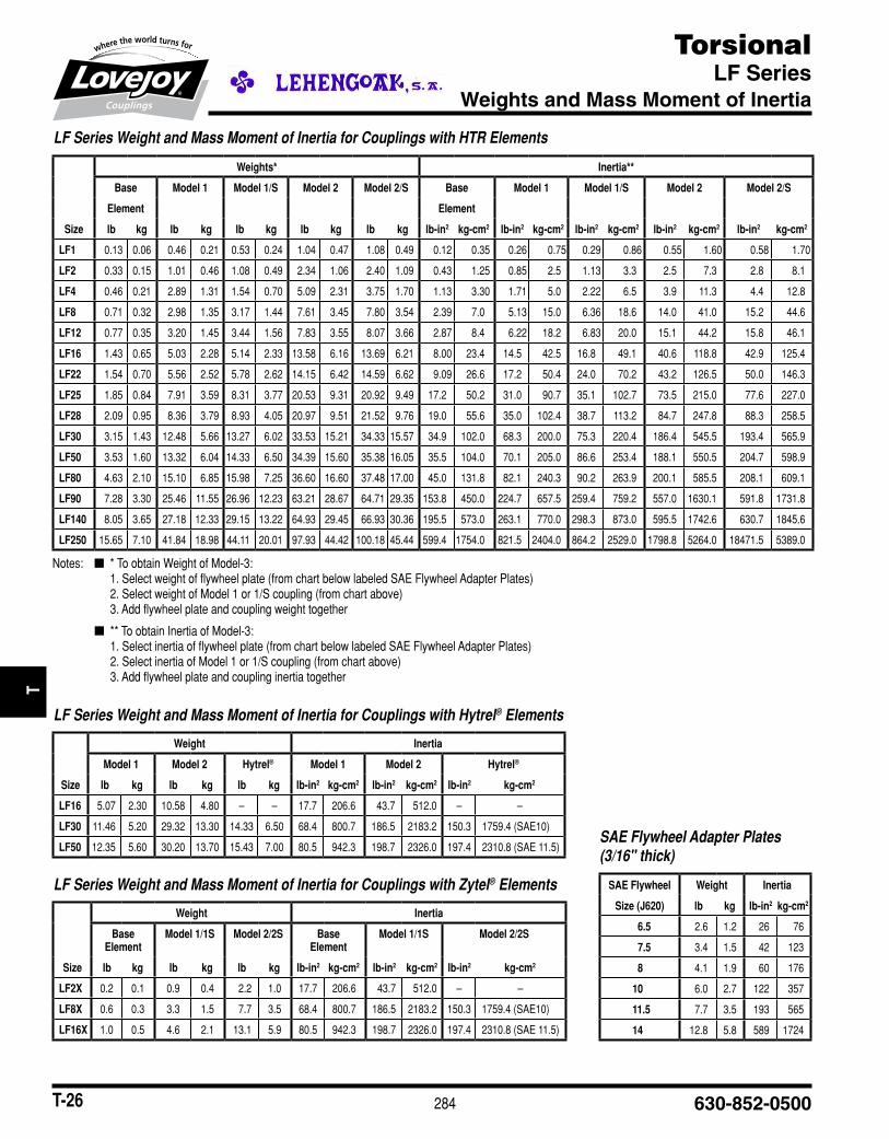
LF Series Weight and Mass Moment of Inertia for Couplings with HTR Elements
Weights* Inertia**
Base Model 1 Model 1/S Model 2 Model 2/S Base Model 1 Model 1/S Model 2 Model 2/S
Element Element
Size lb kg lb kg lb kg lb kg lb kg lb-in2 kg-cm2 lb-in2 kg-cm2 lb-in2 kg-cm2 lb-in2 kg-cm2 lb-in2 kg-cm2
LF1 0.13 0.06 0.46 0.21 0.53 0.24 1.04 0.47 1.08 0.49 0.12 0.35 0.26 0.75 0.29 0.86 0.55 1.60 0.58 1.70
LF2 0.33 0.15 1.01 0.46 1.08 0.49 2.34 1.06 2.40 1.09 0.43 1.25 0.85 2.5 1.13 3.3 2.5 7.3 2.8 8.1
LF4 0.46 0.21 2.89 1.31 1.54 0.70 5.09 2.31 3.75 1.70 1.13 3.30 1.71 5.0 2.22 6.5 3.9 11.3 4.4 12.8
LF8 0.71 0.32 2.98 1.35 3.17 1.44 7.61 3.45 7.80 3.54 2.39 7.0 5.13 15.0 6.36 18.6 14.0 41.0 15.2 44.6
LF12 0.77 0.35 3.20 1.45 3.44 1.56 7.83 3.55 8.07 3.66 2.87 8.4 6.22 18.2 6.83 20.0 15.1 44.2 15.8 46.1
LF16 1.43 0.65 5.03 2.28 5.14 2.33 13.58 6.16 13.69 6.21 8.00 23.4 14.5■ 42.5 16.8 49.1 40.6 118.8 42.9 125.4
LF22 1.54 0.70 5.56 2.52 5.78 2.62 14.15 6.42 14.59 6.62 9.09 26.6 17.2 50.4 24.0 70.2 43.2 126.5 50.0 146.3
LF25 1.85 0.84 7.91 3.59 8.31 3.77 20.53 9.31 20.92 9.49 17.2 50.2 31.0 90.7 35.1 102.7 73.5 215.0 77.6 227.0
LF28 2.09 0.95 8.36 3.79 8.93 4.05 20.97 9.51 21.52 9.76 19.0 55.6 35.0 102.4 38.7 113.2 84.7 247.8 88.3 258.5
LF30 3.15 1.43 12.48 5.66 13.27 6.02 33.53 15.21 34.33 15.57 34.9 102.0 68.3 200.0 75.3 220.4 186.4 545.5 193.4 565.9
LF50 3.53 1.60 13.32 6.04 14.33 6.50 34.39 15.60 35.38 16.05 35.5 104.0 70.1 205.0 86.6 253.4 188.1 550.5 204.7 598.9
LF80 4.63 2.10 15.10 6.85 15.98 7.25 36.60 16.60 37.48 17.00 45.0 131.8 82.1 240.3 90.2 263.9 200.1 585.5 208.1 609.1
LF90 7.28 3.30 25.46 11.55 26.96 12.23 63.21 28.67 64.71 29.35 153.8 450.0 224.7 657.5 259.4 759.2 557.0 1630.1 591.8 1731.8
LF140 8.05 3.65 27.18 12.33 29.15 13.22 64.93 29.45 66.93 30.36 195.5 573.0 263.1 770.0 298.3 873.0 595.5 1742.6 630.7 1845.6
LF250 15.65 7.10 41.84 18.98 44.11 20.01 97.93 44.42 100.18 45.44 599.4 1754.0 821.5 2404.0 864.2 2529.0 1798.8 5264.0 18471.5 5389.0
Notes:■■ n■■■■■■*■To■obtain■Weight■of■Model-3:1.■Select■weight■of■flywheel■plate■(from■chart■below■labeled■SAE■Flywheel■Adapter■Plates)■2.■Select■weight■of■Model■1■or■1/S■coupling■(from■chart■above)■3.■Add■flywheel■plate■and■coupling■weight■together
■ n■■■**■To■obtain■Inertia■of■Model-3:1.■Select■inertia■of■flywheel■plate■(from■chart■below■labeled■SAE■Flywheel■Adapter■Plates)■2.■Select■inertia■of■Model■1■or■1/S■coupling■(from■chart■above)■3.■Add■flywheel■plate■and■coupling■inertia■together
LF Series Weight and Mass Moment of Inertia for Couplings with Hytrel® Elements
Weight Inertia
Model 1 Model 2 Hytrel® Model 1 Model 2 Hytrel®
Size lb kg lb kg lb kg lb-in2 kg-cm2 lb-in2 kg-cm2 lb-in2 kg-cm2
LF16 5.07 2.30 10.58 4.80 – – 17.7 206.6 43.7 512.0 – –
LF30 11.46 5.20 29.32 13.30 14.33 6.50 68.4 800.7 186.5 2183.2 150.3 1759.4■(SAE10)
LF50 12.35 5.60 30.20 13.70 15.43 7.00 80.5 942.3 198.7 2326.0 197.4 2310.8■(SAE■11.5)
LF Series Weight and Mass Moment of Inertia for Couplings with Zytel® Elements
Weight Inertia
Base Element
Model 1/1S Model 2/2S Base Element
Model 1/1S Model 2/2S
Size lb kg lb kg lb kg lb-in2 kg-cm2 lb-in2 kg-cm2 lb-in2 kg-cm2
LF2X 0.2 0.1 0.9 0.4 2.2 1.0 17.7 206.6 43.7 512.0 – –
LF8X 0.6 0.3 3.3 1.5 7.7 3.5 68.4 800.7 186.5 2183.2 150.3 1759.4■(SAE10)
LF16X 1.0 0.5 4.6 2.1 13.1 5.9 80.5 942.3 198.7 2326.0 197.4 2310.8■(SAE■11.5)
SAE Flywheel Adapter Plates (3/16" thick)
SAE Flywheel Weight Inertia
Size (J620) lb kg lb-in2 kg-cm2
6.5 2.6 1.2 26 76
7.5 3.4 1.5 42 123
8 4.1 1.9 60 176
10 6.0 2.7 122 357
11.5 7.7 3.5 193 565
14 12.8 5.8 589 1724
JWJI
SC
JSF
MC
GH
PG
DD
TSP
UJ
VSD
RSL
DED
JWJIS
CJ
SFM
CG
HP
GD
DT
SPU
JVSD
RSLD
ED
285www.lovejoy-inc.com T-27
TorsionalLF Series Floating-Shaft – Models 6 and 6B
Selection Process
Step 1: Torque Capacity Values■for■normal■torque■TKN,■maximum■torque■TKmax,■and■continuous■vibratory■torque■TKw■remain■the■same■and■are■found■in■the■table■of■Performance■Data■on■page■16■and■23.
Step 2: Stiffness Values and Wind-Up Since■2■torsional■rubber■elements■are■used■together■in■series,■values■from■the■Performance■Data■table■on■page■16■and■17■for■dynamic■torsional■stiffness■CTdyn,■static■angular■stiffness■Cw■and■static■axial■stiffness■Ca,■should■be■multiplied■by■1/2.■Values■for■wind-up■should■be■multiplied■by■2.
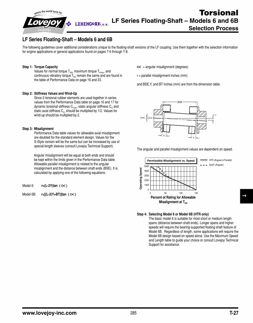
Step 3: Misalignment Performance■Data■table■values■for■allowable■axial■misalignment■are■doubled■for■the■standard■element■design.■Values■for■the■S-Style■version■will■be■the■same■but■can■be■increased■by■use■of■special-length■sleeves■(consult■Lovejoy■Technical■Support).
Angular■misalignment■will■be■equal■at■both■ends■and■should■be■kept■within■the■limits■given■in■the■Performance■Data■table.■■Allowable■parallel■misalignment■is■related■to■the■angular■misalignment■and■the■distance■between■shaft■ends■(BSE).■It■is■■calculated■by■applying■one■of■the■following■equations:
Model■6:■ r=(L-2Y)tan ( )
Model■6B:■ r=[(L-2(Y+BT)]tan ( )
■■=■angular■misalignment■(degrees)
r■=■parallel■misalignment■inches■(mm)
and■BSE,Y,■and■BT■inches■(mm)■are■from■the■dimension■table.
The■angular■and■parallel■misalignment■values■are■dependent■on■speed.
Step 4: Selecting Model 6 or Model 6B (HTR only) The■basic■model■6■is■suitable■for■most■short■or■medium■length■spans■(distance■between■shaft■ends).■Longer■spans■and■higher■speeds■will■require■the■bearing-supported■floating■shaft■feature■of■Model■6B.■■Regardless■of■length,■some■applications■will■require■the■Model■6B■design■based■on■speed■alone.■Use■the■Maximum■Speed■and■Length■table■to■guide■your■choice■or■consult■Lovejoy■Technical■Support■for■assistance.
LF Series Floating-Shaft – Models 6 and 6B The■following■guidelines■cover■additional■considerations■unique■to■the■floating-shaft■versions■of■the■LF■coupling.■Use■them■together■with■the■selection■information■for■engine■applications■or■general■applications■found■on■pages■T-6■through■T-8.
Permissible Misalignment vs. Speed
Percent of Rating for AllowableMisalignment at TKN
Op
erat
ing
Sp
eed
5000
4000
3000
2000
1000
00 50 100 150
HTR (Angular & Parallel)
Zytel® (Angular)
Percent of Rating for Allowable Misalignment at TKN
JWJI
SC
JSF
MC
GH
PG
DD
TSP
UJ
VSD
RSL
DED
JWJIS
CJ
SFM
CG
HP
GD
DT
SPU
JVSD
RSLD
ED