Embed Size (px)
Citation preview
User Manual
JVM-104-O09
We automate your success.
Jetter AGGraeterstrasse 271642 LudwigsburgGermany
PhoneSwitchboard +49 7141 2550-0Sales +49 7141 2550-531Technical Hotline +49 7141 2550-444
E-mailTechnical Hotline [email protected] [email protected]
Translation of the original User Manual
Revision 4.10.1
Date of issue 1/31/2020
This document has been compiled by Jetter AG with due diligence, and based on the knownstate of the art. Revisions and further development of our products are not automaticallymentioned in a reviewed document. Jetter AG shall not be liable for errors in form or content,or for missing updates, as well as for damages or disadvantages resulting from such failure.
Jetter AG Table of contents
JVM-104-O09 User Manual iii
Table of contents1 Introduction ..................................................................................................................................... 6
1.1 Information on this document .................................................................................................. 6
1.2 Typographical conventions...................................................................................................... 6
2 Safety ............................................................................................................................................... 72.1 General information................................................................................................................. 7
2.2 Purpose ................................................................................................................................... 7
2.2.1 Intended use................................................................................................................ 7
2.2.2 Usage other than intended .......................................................................................... 7
2.3 Warnings used in this document ............................................................................................. 7
3 Product description ........................................................................................................................ 83.1 Design ..................................................................................................................................... 8
3.2 Functions................................................................................................................................. 8
3.3 Nameplate ............................................................................................................................... 9
3.4 Scope of delivery..................................................................................................................... 9
4 Technical specifications............................................................................................................... 104.1 Dimensions............................................................................................................................ 10
4.2 Electrical properties............................................................................................................... 10
4.3 Mechanical specifications...................................................................................................... 10
4.4 Environmental conditions ...................................................................................................... 11
4.5 Display................................................................................................................................... 11
4.6 Acoustic signal generator ...................................................................................................... 11
4.7 Ports and interfaces .............................................................................................................. 11
4.7.1 CAN port.................................................................................................................... 11
4.8 Multi-purpose inputs/outputs ................................................................................................. 12
4.9 EMI values............................................................................................................................. 14
5 Mechanical installation................................................................................................................. 165.1 Requirements for the installation location ............................................................................. 16
5.2 Preparing for installation........................................................................................................ 17
5.3 Installing the HMI................................................................................................................... 18
5.4 Mounting the HMI combined with JXM-HMI .......................................................................... 19
6 Electrical connection.................................................................................................................... 216.1 Pin assignment of Deutsch connector................................................................................... 22
6.2 Wiring - Example ................................................................................................................... 23
7 Programming................................................................................................................................. 247.1 Abbreviations, module register properties and formats......................................................... 24
7.2 CANopen® STX API ............................................................................................................. 25
Table of contents Jetter AG
iv JVM-104-O09 User Manual
7.2.1 STX Functions........................................................................................................... 25
7.2.2 CANopen® Object dictionary .................................................................................... 26
7.3 File system ............................................................................................................................ 26
7.3.1 Directories ................................................................................................................. 27
7.4 Storage options - Overview ................................................................................................... 27
7.4.1 Types of program and data memory ......................................................................... 27
7.4.2 Operating system memory ........................................................................................ 27
7.4.3 File system memory .................................................................................................. 27
7.4.4 Application program memory .................................................................................... 27
7.4.5 Flash disk .................................................................................................................. 28
7.4.6 Storing registers and variables.................................................................................. 28
7.4.7 Flag ........................................................................................................................... 28
7.5 Controls and ignition.............................................................................................................. 29
7.5.1 Input keys .................................................................................................................. 29
7.5.2 Digipot ....................................................................................................................... 30
7.5.3 Ignition and OFF delay .............................................................................................. 31
7.6 Multi-purpose inputs .............................................................................................................. 32
7.6.1 Status and instructions .............................................................................................. 33
7.6.2 Analog functions........................................................................................................ 34
7.6.3 Digital functions ......................................................................................................... 35
7.7 Multi-purpose outputs............................................................................................................ 36
7.7.1 Status and instructions .............................................................................................. 37
7.7.2 Analog functions........................................................................................................ 38
7.7.3 Digital functions ......................................................................................................... 39
7.7.4 Multi-purpose outputs PA3 and PA4 functioning as H-bridges ................................. 40
7.8 Runtime registers .................................................................................................................. 40
7.9 Operating system update ...................................................................................................... 42
7.9.1 Updating the operating system via programming tool ............................................... 42
7.9.2 Performing an OS update via JetEasyDownload ...................................................... 42
7.10 Application program .............................................................................................................. 43
8 Registers - Overview..................................................................................................................... 448.1 Default address on the CANopen® bus ................................................................................ 44
8.2 General overview - Registers ................................................................................................ 44
8.3 I/Os - General overview......................................................................................................... 44
8.4 Flags - General overview ...................................................................................................... 44
8.5 Electronic nameplate............................................................................................................. 44
8.6 Electronic name plate (device as a whole)............................................................................ 45
8.7 CAN....................................................................................................................................... 45
8.8 Flash memory........................................................................................................................ 45
Jetter AG Table of contents
JVM-104-O09 User Manual v
8.9 System information................................................................................................................ 45
8.10 General system registers ...................................................................................................... 46
8.11 Application program .............................................................................................................. 47
8.12 File system/data file function ................................................................................................. 48
8.13 Application registers .............................................................................................................. 48
8.14 Display................................................................................................................................... 48
8.15 Flag ....................................................................................................................................... 49
8.16 System Functions.................................................................................................................. 50
9 Register overview - Multi-purpose inputs and outputs ............................................................. 529.1 General overview - Registers ................................................................................................ 52
9.2 Multi-purpose input MFQEx................................................................................................... 53
9.3 Multi-purpose outputs PA1 ... PA4 ........................................................................................ 54
10 Maintenance and repairs .............................................................................................................. 5610.1 Maintenance, repairs and disposal........................................................................................ 56
10.2 Storage and shipment ........................................................................................................... 56
11 Service ........................................................................................................................................... 5711.1 Customer service .................................................................................................................. 57
12 Spare parts and accessories ....................................................................................................... 5812.1 Accessories ........................................................................................................................... 58
Jetter AG Introduction | 1
JVM-104-O09 User Manual 6 / 62
1 Introduction
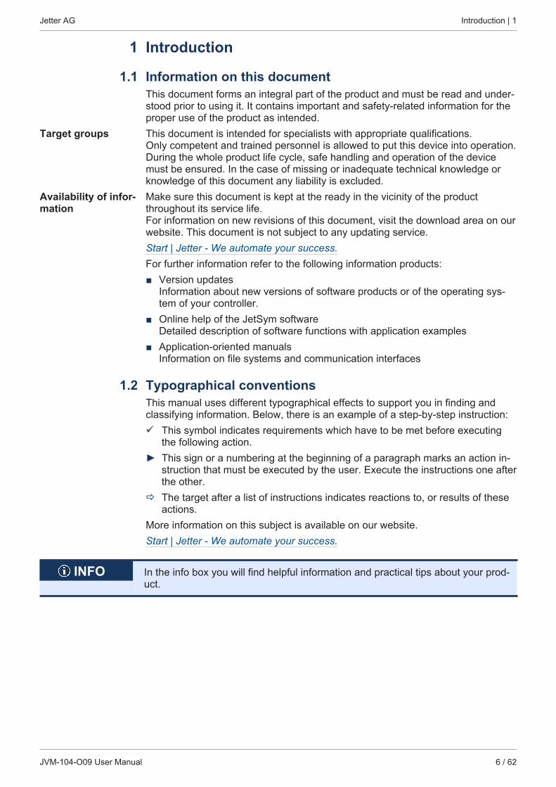
1.1 Information on this documentThis document forms an integral part of the product and must be read and under-stood prior to using it. It contains important and safety-related information for theproper use of the product as intended.
Target groups This document is intended for specialists with appropriate qualifications.Only competent and trained personnel is allowed to put this device into operation. During the whole product life cycle, safe handling and operation of the devicemust be ensured. In the case of missing or inadequate technical knowledge orknowledge of this document any liability is excluded.
Availability of infor-mation
Make sure this document is kept at the ready in the vicinity of the productthroughout its service life. For information on new revisions of this document, visit the download area on ourwebsite. This document is not subject to any updating service.Start | Jetter - We automate your success.For further information refer to the following information products:■ Version updates
Information about new versions of software products or of the operating sys-tem of your controller.
■ Online help of the JetSym softwareDetailed description of software functions with application examples
■ Application-oriented manualsInformation on file systems and communication interfaces
1.2 Typographical conventionsThis manual uses different typographical effects to support you in finding andclassifying information. Below, there is an example of a step-by-step instruction:ü This symbol indicates requirements which have to be met before executing
the following action.► This sign or a numbering at the beginning of a paragraph marks an action in-
struction that must be executed by the user. Execute the instructions one afterthe other.
ð The target after a list of instructions indicates reactions to, or results of theseactions.
More information on this subject is available on our website.Start | Jetter - We automate your success.
INFO In the info box you will find helpful information and practical tips about your prod-uct.
Jetter AG Safety | 2
JVM-104-O09 User Manual 7 / 62
2 Safety
2.1 General informationAt the time of placing on the market, this product corresponds to the current stateof the art and meets the recognized safety rules. Besides this user manual, laws and regulations in the operator's country are rele-vant to the operation of the product. The operator is responsible for complyingwith the directives mentioned below:■ Applicable legislation, rules, and regulations■ Relevant accident prevention regulations■ Accepted safety rules■ EU directives and other country-specific regulations
RoHS 2 The device conforms to the EU directive 2011/65/EU (RoHS 2).
2.2 Purpose2.2.1 Intended use
The JVM-104-O09 is intended for installation in commercial vehicles and self-pro-pelled machines. It is an HMI with integrated controller for exchange of data withperipheral devices.Operate the device only in accordance with the intended conditions of use, andwithin the limits set forth in the technical specifications. Intended use of the product includes its operation in accordance with this man-ual.
SELV/PELV If this device is not used in a vehicle or mobile machine, a SELV or PELV powersupply unit must be used to supply the device.
2.2.2 Usage other than intendedThis device must not be used in technical systems which to a high degree haveto be fail-safe.
Machinery Directive This device is no safety-related part as per Machinery Directive 2006/42/EC, andmust, therefore, not be used for safety-relevant applications. This device is NOTintended for the purpose of personal safety, and must, therefore, not be used toprotect persons.
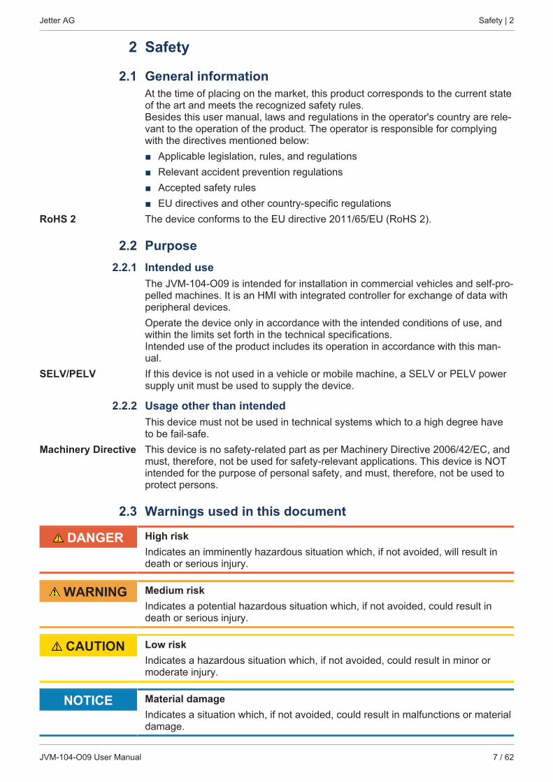
2.3 Warnings used in this document
DANGER High riskIndicates an imminently hazardous situation which, if not avoided, will result indeath or serious injury.
WARNING Medium riskIndicates a potential hazardous situation which, if not avoided, could result indeath or serious injury.
CAUTION Low riskIndicates a hazardous situation which, if not avoided, could result in minor ormoderate injury.
NOTICE Material damageIndicates a situation which, if not avoided, could result in malfunctions or materialdamage.
Jetter AG Product description | 3
JVM-104-O09 User Manual 8 / 62
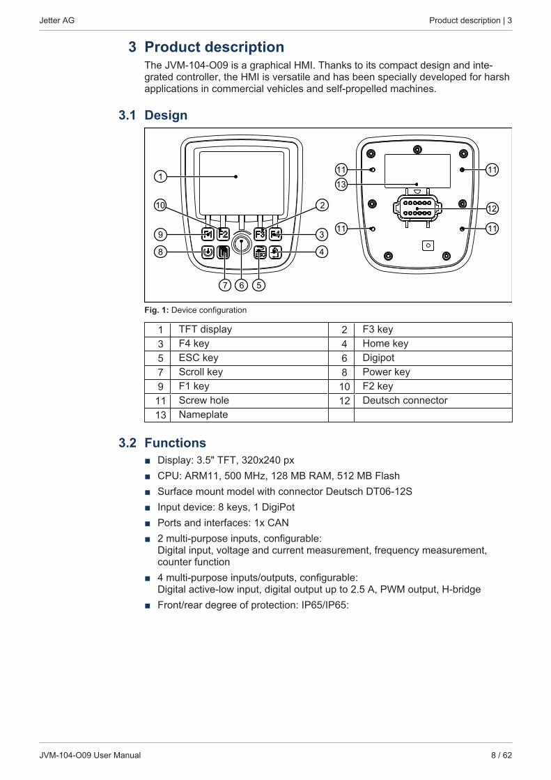
3 Product descriptionThe JVM-104-O09 is a graphical HMI. Thanks to its compact design and inte-grated controller, the HMI is versatile and has been specially developed for harshapplications in commercial vehicles and self-propelled machines.
3.1 Design
113
12
9 3
48
10 2
67 5
11
11 11
11
Fig. 1: Device configuration
1 TFT display 2 F3 key3 F4 key 4 Home key5 ESC key 6 Digipot7 Scroll key 8 Power key9 F1 key 10 F2 key
11 Screw hole 12 Deutsch connector13 Nameplate
3.2 Functions■ Display: 3.5" TFT, 320x240 px■ CPU: ARM11, 500 MHz, 128 MB RAM, 512 MB Flash■ Surface mount model with connector Deutsch DT06-12S■ Input device: 8 keys, 1 DigiPot■ Ports and interfaces: 1x CAN■ 2 multi-purpose inputs, configurable:
Digital input, voltage and current measurement, frequency measurement,counter function
■ 4 multi-purpose inputs/outputs, configurable: Digital active-low input, digital output up to 2.5 A, PWM output, H-bridge
■ Front/rear degree of protection: IP65/IP65:
Jetter AG Product description | 3
JVM-104-O09 User Manual 9 / 62
3.3 Nameplate
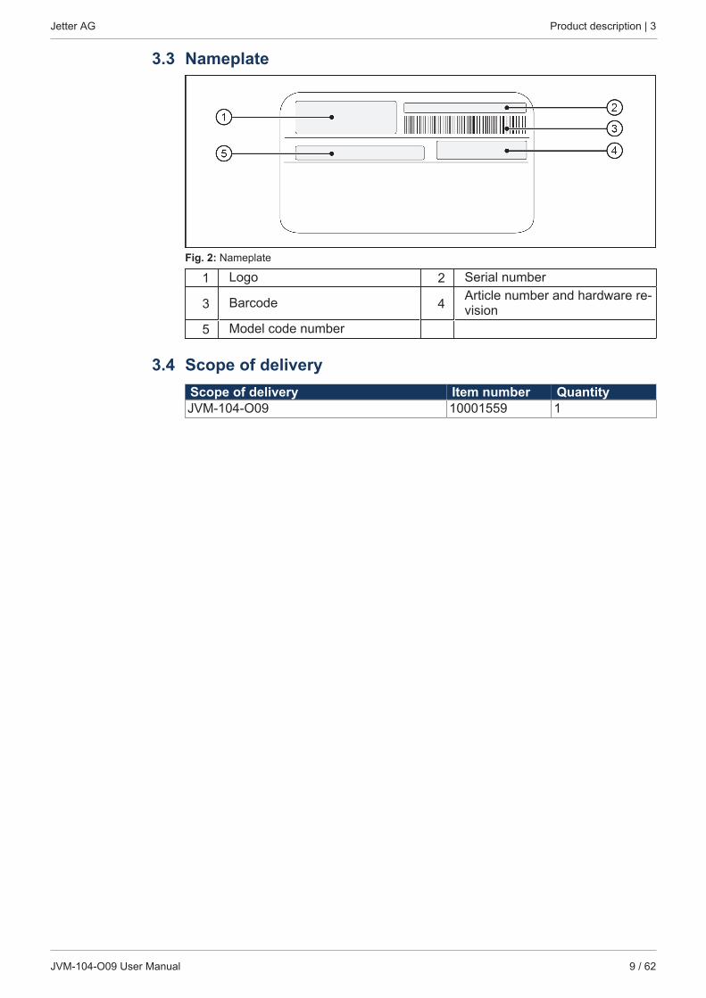
Fig. 2: Nameplate
1 Logo 2 Serial number
3 Barcode 4 Article number and hardware re-vision
5 Model code number
3.4 Scope of deliveryScope of delivery Item number QuantityJVM-104-O09 10001559 1
Jetter AG Technical specifications | 4
JVM-104-O09 User Manual 10 / 62
4 Technical specifications
4.1 Dimensions
119.
8
27.9
55
83
O3.1
4 x
67.3
17.6 28.4
104.9
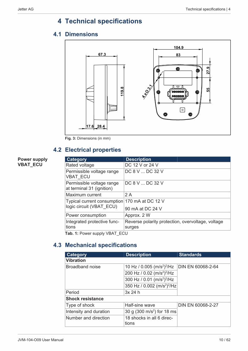
Fig. 3: Dimensions (in mm)
4.2 Electrical propertiesPower supplyVBAT_ECU
Category DescriptionRated voltage DC 12 V or 24 VPermissible voltage rangeVBAT_ECU
DC 8 V ... DC 32 V
Permissible voltage rangeat terminal 31 (ignition)
DC 8 V ... DC 32 V
Maximum current 2 ATypical current consumptionlogic circuit (VBAT_ECU)
170 mA at DC 12 V
90 mA at DC 24 VPower consumption Approx. 2 WIntegrated protective func-tions
Reverse polarity protection, overvoltage, voltagesurges
Tab. 1: Power supply VBAT_ECU
4.3 Mechanical specificationsCategory Description StandardsVibrationBroadband noise 10 Hz / 0.005 (m/s2)2/Hz DIN EN 60068-2-64
200 Hz / 0.02 (m/s2)2/Hz300 Hz / 0.01 (m/s2)2/Hz350 Hz / 0.002 (m/s2)2/Hz
Period 3x 24 hShock resistanceType of shock Half-sine wave DIN EN 60068-2-27Intensity and duration 30 g (300 m/s2) for 18 msNumber and direction 18 shocks in all 6 direc-
tions
Jetter AG Technical specifications | 4
JVM-104-O09 User Manual 11 / 62
Category Description StandardsDegree of protectionFront panel: IP65 DIN EN 60529Rear panel: IP65Tab. 2: Mechanical specifications
4.4 Environmental conditionsCategory Description StandardsOperating temperature -20 … +65 °C ISO 16750-4Climatic conditions Humid heatStorage temperature -20 … +70 °C ISO 16750-4
DIN EN 60068-2-1
DIN EN 60068-2-2Air humidity 10 … 95 % DIN EN 61131-2Pollution degree 2 DIN EN 61131-2Tab. 3: Environmental conditions
4.5 DisplayCategory DescriptionType TFT LCD flat screen monitorResolution 320 x 240 pixelsSize 3.5"Background lighting LED, typically 350 cd/m2, dimmableHorizontal viewing angle 70° to each sideVertical viewing angle 50° from above, 70° from belowTab. 4: Technical data - Display
4.6 Acoustic signal generatorCategory DescriptionType Speakers Adjustable frequency
and volume.Volume 83 dB 10 cm distance and res-
onance frequency 2.670Hz
Tab. 5: Acoustic signal generator
4.7 Ports and interfaces4.7.1 CAN port
CAN interface spec-ification
Category DescriptionBaud rate 250 kBaud … 1 MBaudProtocol CANopen®
Default node ID on the CANopen® bus
127 (0x7F)
Terminating resistor Does not exist.Must be connected externally.
Cable specification Twisted pair conductors, unshieldedTab. 6: CAN interface specification
Jetter AG Technical specifications | 4
JVM-104-O09 User Manual 12 / 62
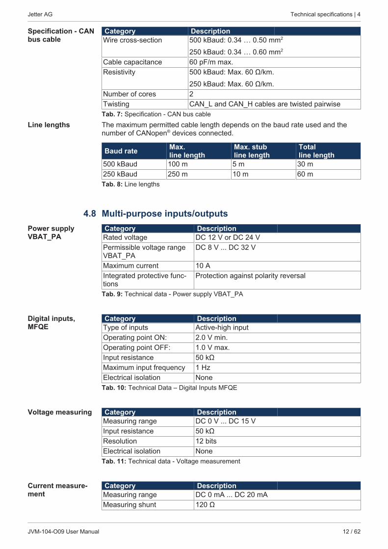
Specification - CANbus cable
Category DescriptionWire cross-section 500 kBaud: 0.34 … 0.50 mm2
250 kBaud: 0.34 … 0.60 mm2
Cable capacitance 60 pF/m max.Resistivity 500 kBaud: Max. 60 Ω/km.
250 kBaud: Max. 60 Ω/km.Number of cores 2Twisting CAN_L and CAN_H cables are twisted pairwiseTab. 7: Specification - CAN bus cable
Line lengths The maximum permitted cable length depends on the baud rate used and thenumber of CANopen® devices connected.
Baud rate Max.line length
Max. stubline length
Totalline length
500 kBaud 100 m 5 m 30 m250 kBaud 250 m 10 m 60 mTab. 8: Line lengths
4.8 Multi-purpose inputs/outputsPower supplyVBAT_PA
Category DescriptionRated voltage DC 12 V or DC 24 VPermissible voltage rangeVBAT_PA
DC 8 V ... DC 32 V
Maximum current 10 AIntegrated protective func-tions
Protection against polarity reversal
Tab. 9: Technical data - Power supply VBAT_PA
Digital inputs,MFQE
Category DescriptionType of inputs Active-high inputOperating point ON: 2.0 V min.Operating point OFF: 1.0 V max.Input resistance 50 kΩMaximum input frequency 1 HzElectrical isolation NoneTab. 10: Technical Data – Digital Inputs MFQE
Voltage measuring Category DescriptionMeasuring range DC 0 V ... DC 15 VInput resistance 50 kΩResolution 12 bitsElectrical isolation NoneTab. 11: Technical data - Voltage measurement
Current measure-ment
Category DescriptionMeasuring range DC 0 mA ... DC 20 mAMeasuring shunt 120 Ω
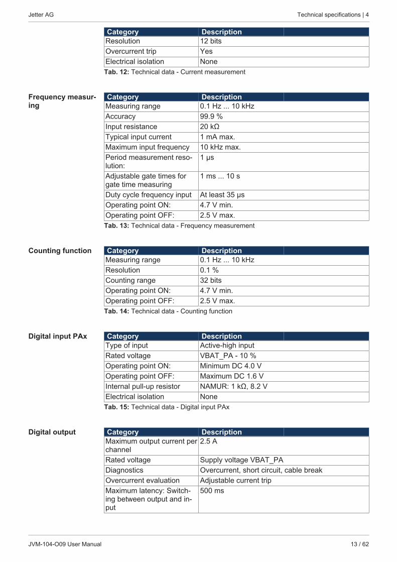
Jetter AG Technical specifications | 4
JVM-104-O09 User Manual 13 / 62
Category DescriptionResolution 12 bitsOvercurrent trip YesElectrical isolation NoneTab. 12: Technical data - Current measurement
Frequency measur-ing
Category DescriptionMeasuring range 0.1 Hz ... 10 kHzAccuracy 99.9 %Input resistance 20 kΩTypical input current 1 mA max.Maximum input frequency 10 kHz max.Period measurement reso-lution:
1 μs
Adjustable gate times forgate time measuring
1 ms ... 10 s
Duty cycle frequency input At least 35 μsOperating point ON: 4.7 V min.Operating point OFF: 2.5 V max.Tab. 13: Technical data - Frequency measurement
Counting function Category DescriptionMeasuring range 0.1 Hz ... 10 kHzResolution 0.1 %Counting range 32 bitsOperating point ON: 4.7 V min.Operating point OFF: 2.5 V max.Tab. 14: Technical data - Counting function
Digital input PAx Category DescriptionType of input Active-high inputRated voltage VBAT_PA - 10 %Operating point ON: Minimum DC 4.0 VOperating point OFF: Maximum DC 1.6 VInternal pull-up resistor NAMUR: 1 kΩ, 8.2 VElectrical isolation NoneTab. 15: Technical data - Digital input PAx
Digital output Category DescriptionMaximum output current perchannel
2.5 A
Rated voltage Supply voltage VBAT_PADiagnostics Overcurrent, short circuit, cable breakOvercurrent evaluation Adjustable current tripMaximum latency: Switch-ing between output and in-put
500 ms
Jetter AG Technical specifications | 4
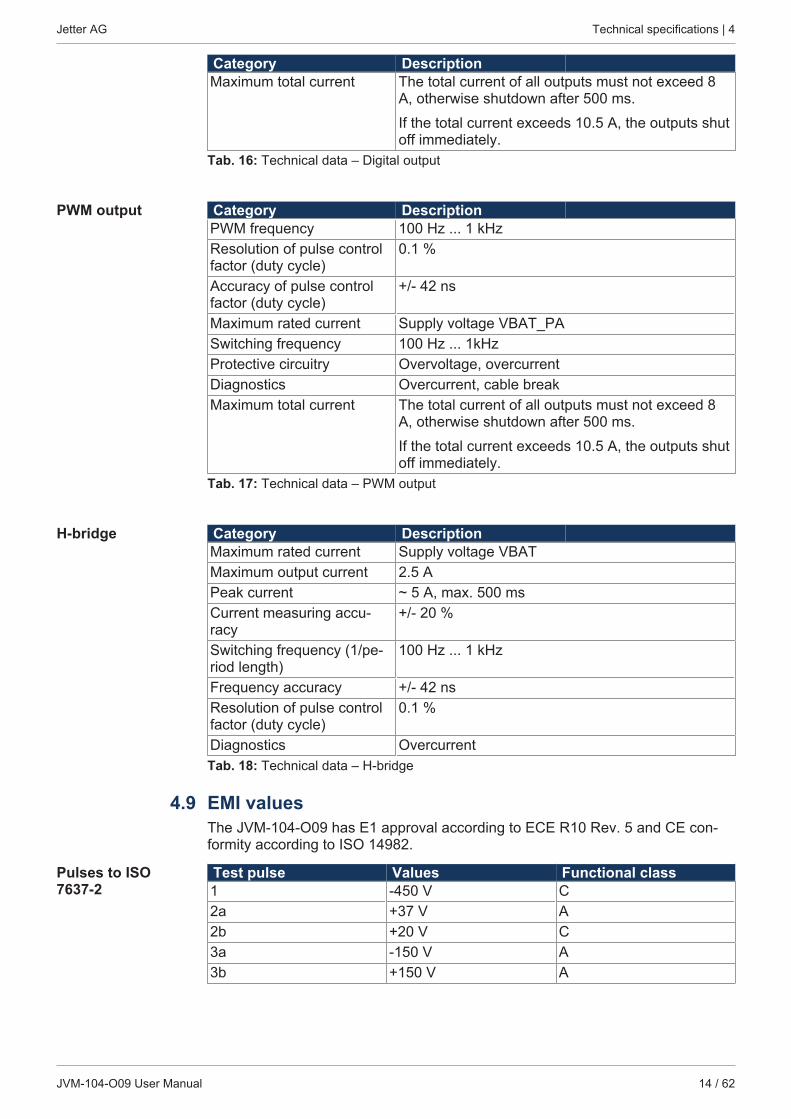
JVM-104-O09 User Manual 14 / 62
Category DescriptionMaximum total current The total current of all outputs must not exceed 8
A, otherwise shutdown after 500 ms.
If the total current exceeds 10.5 A, the outputs shutoff immediately.
Tab. 16: Technical data – Digital output
PWM output Category DescriptionPWM frequency 100 Hz ... 1 kHzResolution of pulse controlfactor (duty cycle)
0.1 %
Accuracy of pulse controlfactor (duty cycle)
+/- 42 ns
Maximum rated current Supply voltage VBAT_PASwitching frequency 100 Hz ... 1kHzProtective circuitry Overvoltage, overcurrentDiagnostics Overcurrent, cable breakMaximum total current The total current of all outputs must not exceed 8
A, otherwise shutdown after 500 ms.
If the total current exceeds 10.5 A, the outputs shutoff immediately.
Tab. 17: Technical data – PWM output
H-bridge Category DescriptionMaximum rated current Supply voltage VBATMaximum output current 2.5 APeak current ~ 5 A, max. 500 msCurrent measuring accu-racy
+/- 20 %
Switching frequency (1/pe-riod length)
100 Hz ... 1 kHz
Frequency accuracy +/- 42 nsResolution of pulse controlfactor (duty cycle)
0.1 %
Diagnostics OvercurrentTab. 18: Technical data – H-bridge
4.9 EMI valuesThe JVM-104-O09 has E1 approval according to ECE R10 Rev. 5 and CE con-formity according to ISO 14982.
Pulses to ISO7637-2
Test pulse Values Functional class1 -450 V C2a +37 V A2b +20 V C3a -150 V A3b +150 V A
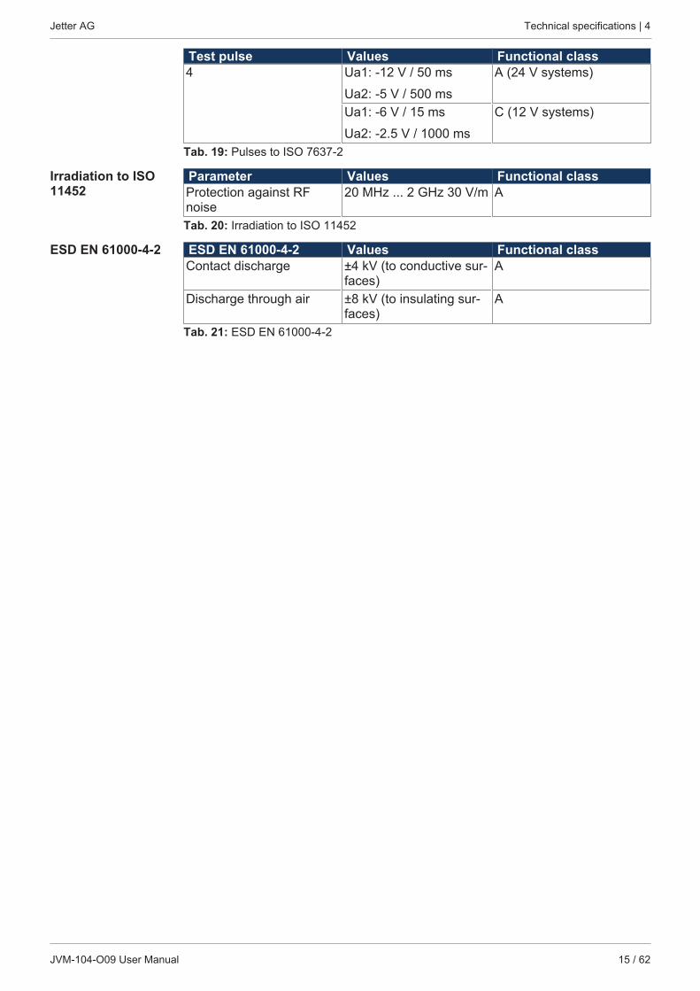
Jetter AG Technical specifications | 4
JVM-104-O09 User Manual 15 / 62
Test pulse Values Functional class4 Ua1: -12 V / 50 ms
Ua2: -5 V / 500 ms
A (24 V systems)
Ua1: -6 V / 15 ms
Ua2: -2.5 V / 1000 ms
C (12 V systems)
Tab. 19: Pulses to ISO 7637-2
Irradiation to ISO11452
Parameter Values Functional classProtection against RFnoise
20 MHz ... 2 GHz 30 V/m A
Tab. 20: Irradiation to ISO 11452
ESD EN 61000-4-2 ESD EN 61000-4-2 Values Functional classContact discharge ±4 kV (to conductive sur-
faces)A
Discharge through air ±8 kV (to insulating sur-faces)
A
Tab. 21: ESD EN 61000-4-2
Jetter AG Mechanical installation | 5
JVM-104-O09 User Manual 16 / 62
5 Mechanical installation
NOTICE Damages to material or functional impairmentWelding on the chassis may cause damages to material of the device, or impairits functions.► Before you start welding, disconnect all connections between the device and
the electric system of the vehicle.► Protect the device from flying sparks and welding beads (splatter).► Do not touch the device with the welding electrode or earth clamp.
5.1 Requirements for the installation locationThe installation location must meet the following requirements:■ The installation location must allow air to circulate.■ The installation location must be of sufficient size.■ The device must be easily accessible to allow for service work.
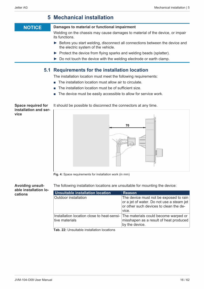
Space required forinstallation and ser-vice
It should be possible to disconnect the connectors at any time.
70
Fig. 4: Space requirements for installation work (in mm)
Avoiding unsuit-able installation lo-cations
The following installation locations are unsuitable for mounting the device:
Unsuitable installation location ReasonOutdoor installation The device must not be exposed to rain
or a jet of water. Do not use a steam jetor other such devices to clean the de-vice.
Installation location close to heat-sensi-tive materials
The materials could become warped ormisshapen as a result of heat producedby the device.
Tab. 22: Unsuitable installation locations
Jetter AG Mechanical installation | 5
JVM-104-O09 User Manual 17 / 62
5.2 Preparing for installationMounting acces-sories
Use the following accessories [} 58] for installation:
Accessories Item numberMounting plate for RAM Mount ball consisting of mounting plate and screws for housing withDeutsch or M12 connector, without RAM mount attachments
10001621
ORMounting plate for RAM Mount arm with suction cup consisting of mounting plate and screws for housings withDeutsch/M12 connector including RAM Mount arm with suc-tion cup
10001551
Tab. 23: Mounting accessories
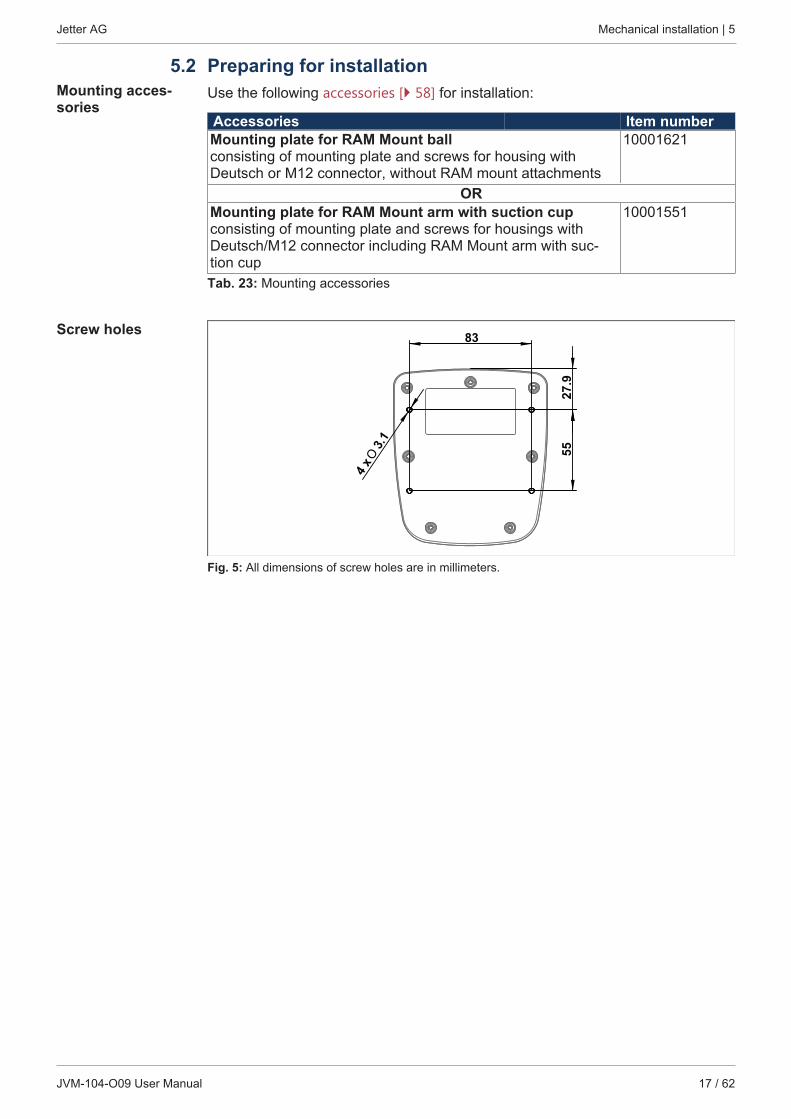
Screw holes
27.9
55
83
O3.1
4 x
Fig. 5: All dimensions of screw holes are in millimeters.
Jetter AG Mechanical installation | 5
JVM-104-O09 User Manual 18 / 62
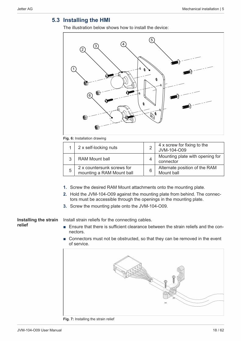
5.3 Installing the HMIThe illustration below shows how to install the device:
23 4
5
1
6
Fig. 6: Installation drawing
1 2 x self-locking nuts 2 4 x screw for fixing to theJVM-104-O09
3 RAM Mount ball 4 Mounting plate with opening forconnector
5 2 x countersunk screws formounting a RAM Mount ball 6 Alternate position of the RAM
Mount ball
1. Screw the desired RAM Mount attachments onto the mounting plate.2. Hold the JVM-104-O09 against the mounting plate from behind. The connec-
tors must be accessible through the openings in the mounting plate.3. Screw the mounting plate onto the JVM-104-O09.
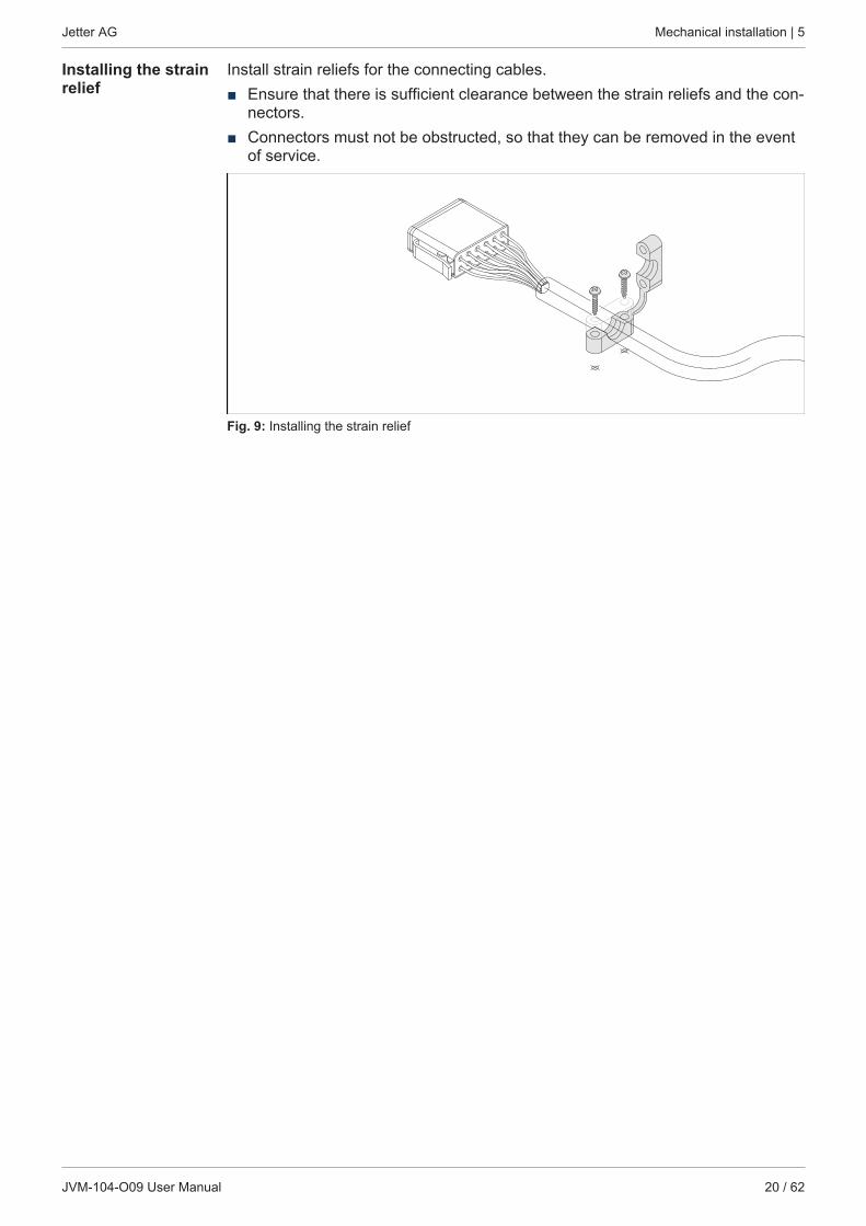
Installing the strainrelief
Install strain reliefs for the connecting cables.■ Ensure that there is sufficient clearance between the strain reliefs and the con-
nectors.■ Connectors must not be obstructed, so that they can be removed in the event
of service.
Fig. 7: Installing the strain relief
Jetter AG Mechanical installation | 5
JVM-104-O09 User Manual 19 / 62
5.4 Mounting the HMI combined with JXM-HMIMounting acces-sories
Use the following accessories [} 58] for installation:
Accessories Item numberMounting plate for JVM-104-O09 combined with a JXM-HMIfor RAM Mount ballconsisting of mounting plate and screws for housing withDeutsch or M12 connector, without RAM mount attachments
10001832
Tab. 24: Mounting accessories
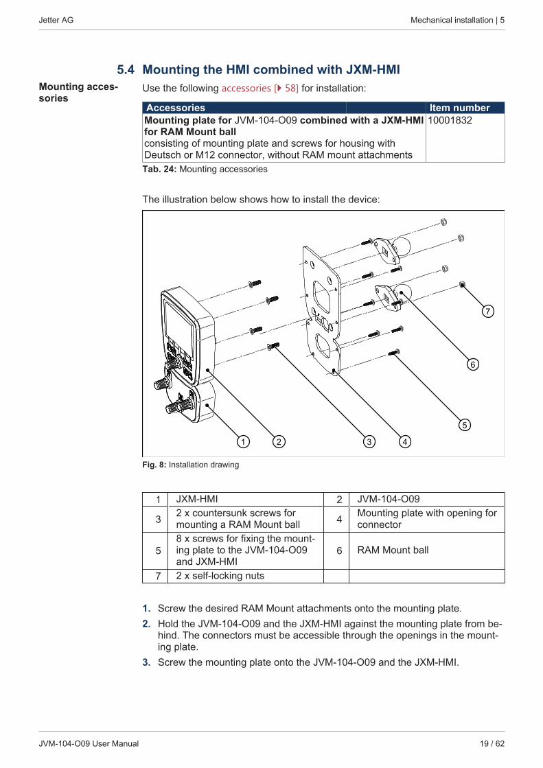
The illustration below shows how to install the device:
1 2 43
7
6
5
Fig. 8: Installation drawing
1 JXM-HMI 2 JVM-104-O09
3 2 x countersunk screws formounting a RAM Mount ball 4 Mounting plate with opening for
connector
58 x screws for fixing the mount-ing plate to the JVM-104-O09and JXM-HMI
6 RAM Mount ball
7 2 x self-locking nuts
1. Screw the desired RAM Mount attachments onto the mounting plate.2. Hold the JVM-104-O09 and the JXM-HMI against the mounting plate from be-
hind. The connectors must be accessible through the openings in the mount-ing plate.
3. Screw the mounting plate onto the JVM-104-O09 and the JXM-HMI.
Jetter AG Mechanical installation | 5
JVM-104-O09 User Manual 20 / 62
Installing the strainrelief
Install strain reliefs for the connecting cables.■ Ensure that there is sufficient clearance between the strain reliefs and the con-
nectors.■ Connectors must not be obstructed, so that they can be removed in the event
of service.
Fig. 9: Installing the strain relief

Jetter AG Electrical connection | 6
JVM-104-O09 User Manual 21 / 62
6 Electrical connection
NOTICE Damages to material or functional impairmentImproper implementation of the wiring harness may cause mechanical stress.► Protect the cables from bending, twisting or chafing.► Install strain reliefs for the connecting cables.
NOTICE Surges resulting from missing protection or fusingSurges may cause malfunctions or damage to the product.► Protect the voltage inputs from surges according to the requirements.► Ensure that the device is handled in accordance with ESD regulations.
Jetter AG Electrical connection | 6
JVM-104-O09 User Manual 22 / 62
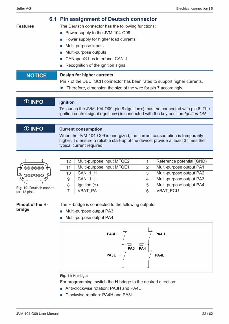
6.1 Pin assignment of Deutsch connectorFeatures The Deutsch connector has the following functions:
■ Power supply to the JVM-104-O09■ Power supply for higher load currents■ Multi-purpose inputs■ Multi-purpose outputs■ CANopen® bus interface: CAN 1■ Recognition of the ignition signal
NOTICE Design for higher currentsPin 7 of the DEUTSCH connector has been rated to support higher currents.► Therefore, dimension the size of the wire for pin 7 accordingly.
INFO IgnitionTo launch the JVM-104-O09, pin 8 (Ignition+) must be connected with pin 6. Theignition control signal (Ignition+) is connected with the key position Ignition ON.
INFO Current consumptionWhen the JVM-104-O09 is energized, the current consumption is temporarilyhigher. To ensure a reliable start-up of the device, provide at least 3 times thetypical current required.
1 6
712Fig. 10: Deutsch connec-tor, 12 pins
12 Multi-purpose input MFQE2 1 Reference potential (GND)11 Multi-purpose input MFQE1 2 Multi-purpose output PA110 CAN_1_H 3 Multi-purpose output PA29 CAN_1_L 4 Multi-purpose output PA38 Ignition (+) 5 Multi-purpose output PA47 VBAT_PA 6 VBAT_ECU
Pinout of the H-bridge
The H-bridge is connected to the following outputs:■ Multi-purpose output PA3■ Multi-purpose output PA4
PA3H
PA3L
PA4H
PA4L
PA3 PA4
Fig. 11: H-bridges
For programming, switch the H-bridge to the desired direction:■ Anti-clockwise rotation: PA3H and PA4L■ Clockwise rotation: PA4H and PA3L
Jetter AG Electrical connection | 6
JVM-104-O09 User Manual 23 / 62
Mating parts Compatible mating parts for the 12-pin DEUTSCH connector are as follows:
Category DescriptionManufacturer DeutschManufacturer item num-ber - Housing
DT06-12S
Manufacturer item num-ber - Wedgelock
W12S
Manufacturer item num-ber - Crimp contact (re-ceptacle)
0-462-201-16141
Wire size range 1.0 ... 1.5 mm2 (AWG 18 ... 16)
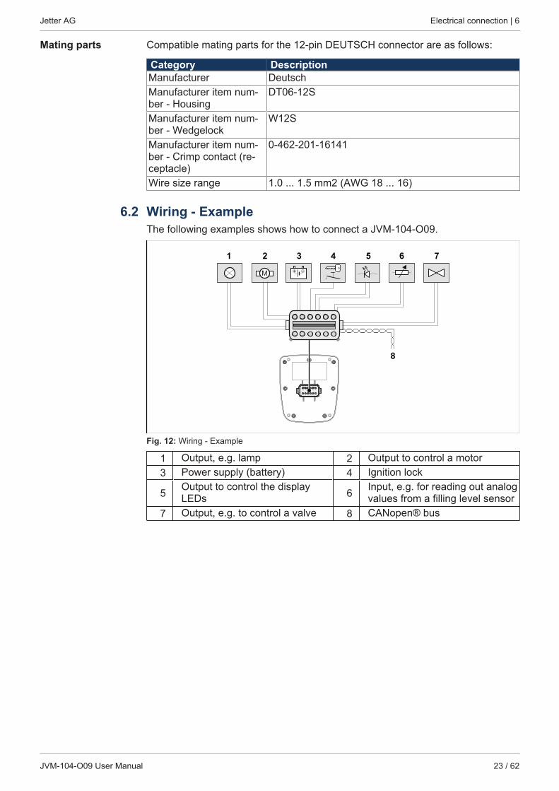
6.2 Wiring - ExampleThe following examples shows how to connect a JVM-104-O09.
M
1 2 3 4 5 6 7
8
Fig. 12: Wiring - Example
1 Output, e.g. lamp 2 Output to control a motor3 Power supply (battery) 4 Ignition lock
5 Output to control the displayLEDs 6 Input, e.g. for reading out analog
values from a filling level sensor7 Output, e.g. to control a valve 8 CANopen® bus
Jetter AG Programming | 7
JVM-104-O09 User Manual 24 / 62
7 Programming
7.1 Abbreviations, module register properties and formatsAbbreviations The abbreviations used in this document are listed in the table below:
Abbreviation DescriptionR 100 Register 100MR 150 Module register 150Tab. 25: Abbreviations
Module registerproperties
Each module register is characterized by certain properties. For many moduleregisters most properties are identical. For example, their value after reset is 0. Inthe following description, module register properties are mentioned only if a prop-erty deviates from the default properties listed below.
Property Standard designType of access Read/writeValue after reset 0 or undefined (e.g. revision/version number)Takes effect ImmediatelyWrite access AlwaysData type IntegerTab. 26: Module register properties
Numerical formats The numerical formats used in this document are listed in the table below:
Notation Format of numerical val-ues
100 Decimal0x100 Hexadecimal0b100 BinaryTab. 27: Numerical formats
JetSym sample pro-grams
The notation for sample programs used in this document is listed in the table be-low:
Notation Format of numerical val-ues
Var, When, Task KeywordBitClear(); Commands100 0x100 0b100 Constant numerical values// This is a com-ment
Comment
// ... Further program processingTab. 28: JetSym sample programs
Jetter AG Programming | 7
JVM-104-O09 User Manual 25 / 62
7.2 CANopen® STX APICANopen® is an open standard for networking and communication, e.g. in the au-tomotive sector. The CANopen® protocol has been further developed by the CiAe.V. (CAN in Automation) and works on the physical layer with CAN Highspeed inaccordance with ISO 11898.
Specifications The CANopen® specifications can be obtained from the CiA e.V. homepage athttp://www.can-cia.org. The key specification documents are:■ CiA DS 301 - This document is also known as the communication profile and
describes the fundamental services and protocols used under CANopen®.■ CiA DS 302 - Framework for programmable devices (CANopen® Manager,
SDO Manager)■ CiA DR 303 - Information on cables and connectors■ CiA DS 4xx - These documents describe the behavior of a number of device
classes in, what are known as, device profiles.
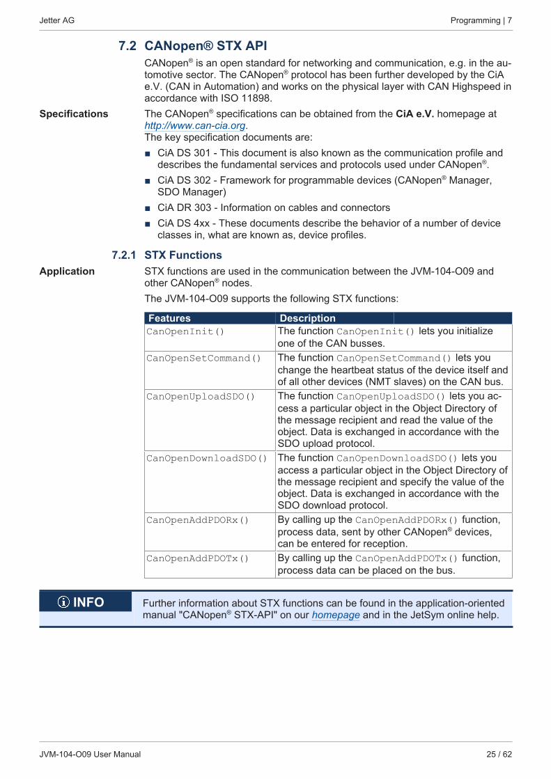
7.2.1 STX FunctionsApplication STX functions are used in the communication between the JVM-104-O09 and
other CANopen® nodes.The JVM-104-O09 supports the following STX functions:
Features DescriptionCanOpenInit() The function CanOpenInit() lets you initialize
one of the CAN busses.CanOpenSetCommand() The function CanOpenSetCommand() lets you
change the heartbeat status of the device itself andof all other devices (NMT slaves) on the CAN bus.
CanOpenUploadSDO() The function CanOpenUploadSDO() lets you ac-cess a particular object in the Object Directory ofthe message recipient and read the value of theobject. Data is exchanged in accordance with theSDO upload protocol.
CanOpenDownloadSDO() The function CanOpenDownloadSDO() lets youaccess a particular object in the Object Directory ofthe message recipient and specify the value of theobject. Data is exchanged in accordance with theSDO download protocol.
CanOpenAddPDORx() By calling up the CanOpenAddPDORx() function,process data, sent by other CANopen® devices,can be entered for reception.
CanOpenAddPDOTx() By calling up the CanOpenAddPDOTx() function,process data can be placed on the bus.
INFO Further information about STX functions can be found in the application-orientedmanual "CANopen® STX-API" on our homepage and in the JetSym online help.
Jetter AG Programming | 7
JVM-104-O09 User Manual 26 / 62
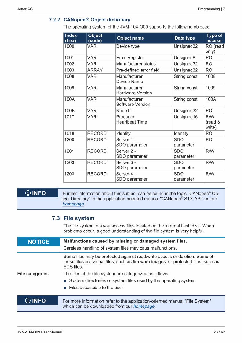
7.2.2 CANopen® Object dictionaryThe operating system of the JVM-104-O09 supports the following objects:
Index(hex)
Object(code) Object name Data type Type of
access1000 VAR Device type Unsigned32 RO (read
only)1001 VAR Error Register Unsigned8 RO1002 VAR Manufacturer status Unsigned32 RO1003 ARRAY Pre-defined error field Unsigned32 RO1008 VAR Manufacturer
Device NameString const 1008
1009 VAR Manufacturer Hardware Version
String const 1009
100A VAR Manufacturer Software Version
String const 100A
100B VAR Node ID Unsigned32 RO1017 VAR Producer
Heartbeat TimeUnsigned16 R/W
(read &write)
1018 RECORD Identity Identity RO1200 RECORD Server 1 -
SDO parameterSDOparameter
RO
1201 RECORD Server 2 - SDO parameter
SDOparameter
R/W
1203 RECORD Server 3 - SDO parameter
SDOparameter
R/W
1203 RECORD Server 4 - SDO parameter
SDOparameter
R/W
INFO Further information about this subject can be found in the topic "CANopen® Ob-ject Directory" in the application-oriented manual "CANopen® STX-API" on ourhomepage.
7.3 File systemThe file system lets you access files located on the internal flash disk. Whenproblems occur, a good understanding of the file system is very helpful.
NOTICE Malfunctions caused by missing or damaged system files.Careless handling of system files may caus malfunctions.
Some files may be protected against read/write access or deletion. Some ofthese files are virtual files, such as firmware images, or protected files, such asEDS files.
File categories The files of the file system are categorized as follows:■ System directories or system files used by the operating system■ Files accessible to the user
INFO For more information refer to the application-oriented manual "File System"which can be downloaded from our homepage.
Jetter AG Programming | 7
JVM-104-O09 User Manual 27 / 62
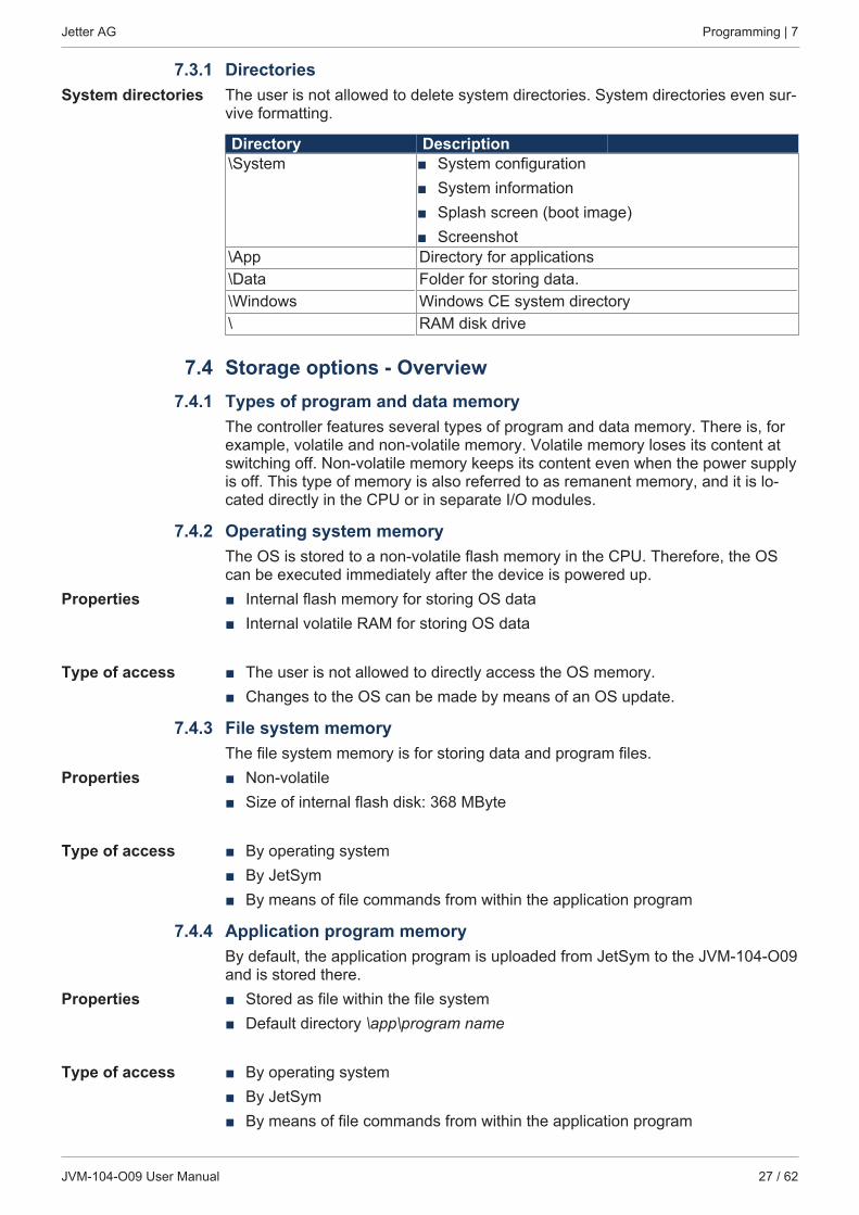
7.3.1 DirectoriesSystem directories The user is not allowed to delete system directories. System directories even sur-
vive formatting.
Directory Description\System ■ System configuration
■ System information■ Splash screen (boot image)■ Screenshot
\App Directory for applications\Data Folder for storing data.\Windows Windows CE system directory\ RAM disk drive
7.4 Storage options - Overview7.4.1 Types of program and data memory
The controller features several types of program and data memory. There is, forexample, volatile and non-volatile memory. Volatile memory loses its content atswitching off. Non-volatile memory keeps its content even when the power supplyis off. This type of memory is also referred to as remanent memory, and it is lo-cated directly in the CPU or in separate I/O modules.
7.4.2 Operating system memoryThe OS is stored to a non-volatile flash memory in the CPU. Therefore, the OScan be executed immediately after the device is powered up.
Properties ■ Internal flash memory for storing OS data■ Internal volatile RAM for storing OS data
Type of access ■ The user is not allowed to directly access the OS memory.■ Changes to the OS can be made by means of an OS update.
7.4.3 File system memoryThe file system memory is for storing data and program files.
Properties ■ Non-volatile■ Size of internal flash disk: 368 MByte
Type of access ■ By operating system■ By JetSym■ By means of file commands from within the application program
7.4.4 Application program memoryBy default, the application program is uploaded from JetSym to the JVM-104-O09and is stored there.
Properties ■ Stored as file within the file system■ Default directory \app\program name
Type of access ■ By operating system■ By JetSym■ By means of file commands from within the application program
Jetter AG Programming | 7
JVM-104-O09 User Manual 28 / 62
7.4.5 Flash diskData can be stored directly on the flash disk. The following rules apply when us-ing a flash disk:■ Do not open more than 8 files at a time.■ Separate directory names by a slash “/”.■ The properties of all created files hold their creation date and time as provided
by the controller.■ Date, time, and file size are not available for all system files.
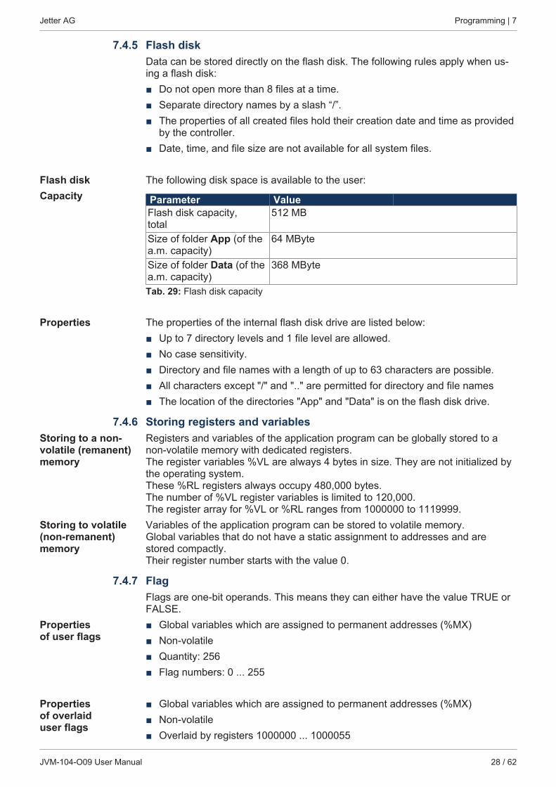
Flash diskCapacity
The following disk space is available to the user:
Parameter ValueFlash disk capacity,total
512 MB
Size of folder App (of thea.m. capacity)
64 MByte
Size of folder Data (of thea.m. capacity)
368 MByte
Tab. 29: Flash disk capacity
Properties The properties of the internal flash disk drive are listed below:■ Up to 7 directory levels and 1 file level are allowed.■ No case sensitivity.■ Directory and file names with a length of up to 63 characters are possible.■ All characters except "/" and ".." are permitted for directory and file names■ The location of the directories "App" and "Data" is on the flash disk drive.
7.4.6 Storing registers and variablesStoring to a non-volatile (remanent)memory
Registers and variables of the application program can be globally stored to anon-volatile memory with dedicated registers.The register variables %VL are always 4 bytes in size. They are not initialized bythe operating system. These %RL registers always occupy 480,000 bytes.The number of %VL register variables is limited to 120,000. The register array for %VL or %RL ranges from 1000000 to 1119999.
Storing to volatile(non-remanent)memory
Variables of the application program can be stored to volatile memory.Global variables that do not have a static assignment to addresses and arestored compactly. Their register number starts with the value 0.
7.4.7 FlagFlags are one-bit operands. This means they can either have the value TRUE orFALSE.
Propertiesof user flags
■ Global variables which are assigned to permanent addresses (%MX)■ Non-volatile■ Quantity: 256■ Flag numbers: 0 ... 255
Propertiesof overlaiduser flags
■ Global variables which are assigned to permanent addresses (%MX)■ Non-volatile■ Overlaid by registers 1000000 ... 1000055
Jetter AG Programming | 7
JVM-104-O09 User Manual 29 / 62
■ Quantity: 1,792■ Flag numbers: 256 ... 2047
Properties of spe-cial flags
■ Global variables which are assigned to permanent addresses (%MX)■ When the operating system is launched, special flags are initialized using their
default values.■ Quantity: 256■ Flag numbers: 2048 ... 2303
Type of access ■ By JetSym■ From HMIs■ From the application program
7.5 Controls and ignitionThis chapter describes how to program the controls and ignition of the JVM-104-O09.
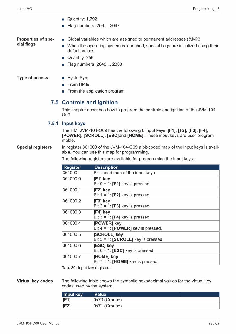
7.5.1 Input keysThe HMI JVM-104-O09 has the following 8 input keys: [F1], [F2], [F3], [F4],[POWER], [SCROLL], [ESC]and [HOME]. These input keys are user-program-mable.
Special registers In register 361000 of the JVM-104-O09 a bit-coded map of the input keys is avail-able. You can use this map for programming.The following registers are available for programming the input keys:
Register Description361000 Bit-coded map of the input keys361000.0 [F1] key
Bit 0 = 1: [F1] key is pressed.361000.1 [F2] key
Bit 1 = 1: [F2] key is pressed.361000.2 [F3] key
Bit 2 = 1: [F3] key is pressed.361000.3 [F4] key
Bit 3 = 1: [F4] key is pressed.361000.4 [POWER] key
Bit 4 = 1: [POWER] key is pressed.361000.5 [SCROLL] key
Bit 5 = 1: [SCROLL] key is pressed.361000.6 [ESC] key
Bit 6 = 1: [ESC] key is pressed.361000.7 [HOME] key
Bit 7 = 1: [HOME] key is pressed.Tab. 30: Input key registers
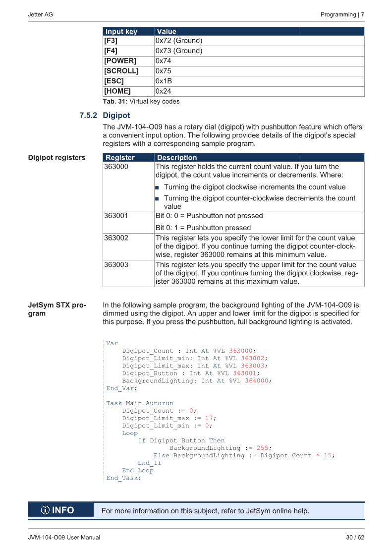
Virtual key codes The following table shows the symbolic hexadecimal values for the virtual keycodes used by the system.
Input key Value[F1] 0x70 (Ground)[F2] 0x71 (Ground)
Jetter AG Programming | 7
JVM-104-O09 User Manual 30 / 62
Input key Value[F3] 0x72 (Ground)[F4] 0x73 (Ground)[POWER] 0x74[SCROLL] 0x75[ESC] 0x1B[HOME] 0x24Tab. 31: Virtual key codes
7.5.2 DigipotThe JVM-104-O09 has a rotary dial (digipot) with pushbutton feature which offersa convenient input option. The following provides details of the digipot's specialregisters with a corresponding sample program.
Digipot registers Register Description363000 This register holds the current count value. If you turn the
digipot, the count value increments or decrements. Where:
■ Turning the digipot clockwise increments the count value■ Turning the digipot counter-clockwise decrements the count
value363001 Bit 0: 0 = Pushbutton not pressed
Bit 0: 1 = Pushbutton pressed363002 This register lets you specify the lower limit for the count value
of the digipot. If you continue turning the digipot counter-clock-wise, register 363000 remains at this minimum value.
363003 This register lets you specify the upper limit for the count valueof the digipot. If you continue turning the digipot clockwise, reg-ister 363000 remains at this maximum value.
JetSym STX pro-gram
In the following sample program, the background lighting of the JVM-104-O09 isdimmed using the digipot. An upper and lower limit for the digipot is specified forthis purpose. If you press the pushbutton, full background lighting is activated.
Var Digipot_Count : Int At %VL 363000; Digipot_Limit_min: Int At %VL 363002; Digipot_Limit_max: Int At %VL 363003; Digipot_Button : Int At %VL 363001; BackgroundLighting: Int At %VL 364000;End_Var;
Task Main Autorun Digipot_Count := 0; Digipot_Limit_max := 17; Digipot_Limit_min := 0; Loop If Digipot_Button Then BackgroundLighting := 255; Else BackgroundLighting := Digipot_Count * 15; End_If End_LoopEnd_Task;
INFO For more information on this subject, refer to JetSym online help.
Jetter AG Programming | 7
JVM-104-O09 User Manual 31 / 62
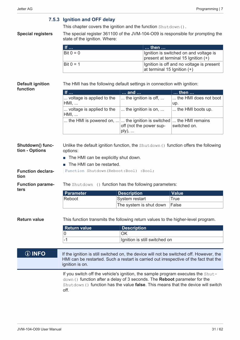
7.5.3 Ignition and OFF delayThis chapter covers the ignition and the function Shutdown().
Special registers The special register 361100 of the JVM-104-O09 is responsible for prompting thestate of the ignition. Where:
If … … then …Bit 0 = 0 Ignition is switched on and voltage is
present at terminal 15 Ignition (+)Bit 0 = 1 Ignition is off and no voltage is present
at terminal 15 Ignition (+)
Default ignitionfunction
The HMI has the following default settings in connection with ignition:
If … … and … … then …... voltage is applied to theHMI, ...
... the ignition is off, ... ... the HMI does not bootup.
... voltage is applied to theHMI, ...
... the ignition is on, ... ... the HMI boots up.
... the HMI is powered on, ... ... the ignition is switchedoff (not the power sup-ply), ...
... the HMI remainsswitched on.
Shutdown() func-tion - Options
Unlike the default ignition function, the Shutdown() function offers the followingoptions:■ The HMI can be explicitly shut down.■ The HMI can be restarted.
Function declara-tion
Function Shutdown(Reboot:Bool) :Bool;
Function parame-ters
The Shutdown () function has the following parameters:
Parameter Description ValueReboot System restart True
The system is shut down False
Return value This function transmits the following return values to the higher-level program.
Return value Description0 OK-1 Ignition is still switched on
INFO If the ignition is still switched on, the device will not be switched off. However, theHMI can be restarted. Such a restart is carried out irrespective of the fact that theignition is on.
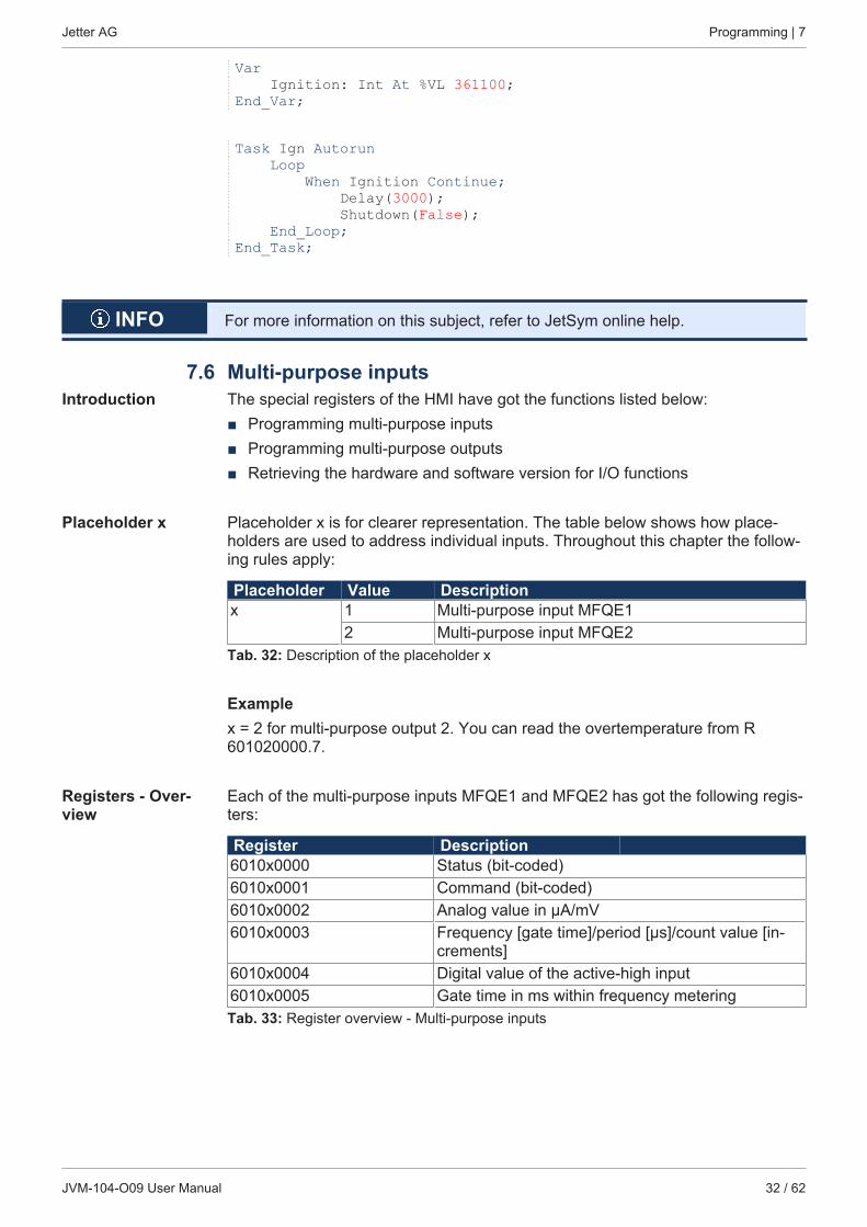
If you switch off the vehicle's ignition, the sample program executes the Shut-down() function after a delay of 3 seconds. The Reboot parameter for theShutdown() function has the value false. This means that the device will switchoff.
Jetter AG Programming | 7
JVM-104-O09 User Manual 32 / 62
Var Ignition: Int At %VL 361100;End_Var;
Task Ign Autorun Loop When Ignition Continue; Delay(3000); Shutdown(False); End_Loop;End_Task;
INFO For more information on this subject, refer to JetSym online help.
7.6 Multi-purpose inputsIntroduction The special registers of the HMI have got the functions listed below:
■ Programming multi-purpose inputs■ Programming multi-purpose outputs■ Retrieving the hardware and software version for I/O functions
Placeholder x Placeholder x is for clearer representation. The table below shows how place-holders are used to address individual inputs. Throughout this chapter the follow-ing rules apply:
Placeholder Value Descriptionx 1 Multi-purpose input MFQE1
2 Multi-purpose input MFQE2Tab. 32: Description of the placeholder x
Examplex = 2 for multi-purpose output 2. You can read the overtemperature from R601020000.7.
Registers - Over-view
Each of the multi-purpose inputs MFQE1 and MFQE2 has got the following regis-ters:
Register Description6010x0000 Status (bit-coded)6010x0001 Command (bit-coded)6010x0002 Analog value in µA/mV6010x0003 Frequency [gate time]/period [μs]/count value [in-
crements]6010x0004 Digital value of the active-high input6010x0005 Gate time in ms within frequency meteringTab. 33: Register overview - Multi-purpose inputs
Jetter AG Programming | 7
JVM-104-O09 User Manual 33 / 62
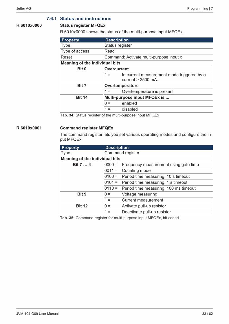
7.6.1 Status and instructionsR 6010x0000 Status register MFQEx
R 6010x0000 shows the status of the multi-purpose input MFQEx.
Property DescriptionType Status registerType of access ReadReset Command: Activate multi-purpose input xMeaning of the individual bits
Bit 0 Overcurrent1 = In current measurement mode triggered by a
current > 2500 mA.Bit 7 Overtemperature
1 = Overtemperature is presentBit 14 Multi-purpose input MFQEx is ...
0 = enabled1 = disabled
Tab. 34: Status register of the multi-purpose input MFQEx
R 6010x0001 Command register MFQExThe command register lets you set various operating modes and configure the in-put MFQEx.
Property DescriptionType Command registerMeaning of the individual bits
Bit 7 … 4 0000 = Frequency measurement using gate time0011 = Counting mode0100 = Period time measuring, 10 s timeout0101 = Period time measuring, 1 s timeout0110 = Period time measuring, 100 ms timeout
Bit 9 0 = Voltage measuring1 = Current measurement
Bit 12 0 = Activate pull-up resistor1 = Deactivate pull-up resistor
Tab. 35: Command register for multi-purpose input MFQEx, bit-coded
Jetter AG Programming | 7
JVM-104-O09 User Manual 34 / 62
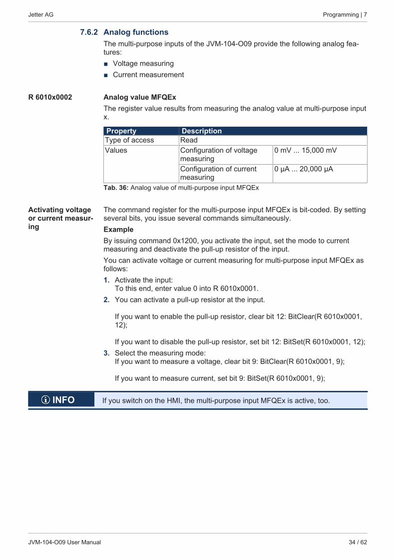
7.6.2 Analog functionsThe multi-purpose inputs of the JVM-104-O09 provide the following analog fea-tures:■ Voltage measuring■ Current measurement
R 6010x0002 Analog value MFQExThe register value results from measuring the analog value at multi-purpose inputx.
Property DescriptionType of access ReadValues Configuration of voltage
measuring0 mV ... 15,000 mV
Configuration of currentmeasuring
0 μA ... 20,000 μA
Tab. 36: Analog value of multi-purpose input MFQEx
Activating voltageor current measur-ing
The command register for the multi-purpose input MFQEx is bit-coded. By settingseveral bits, you issue several commands simultaneously.ExampleBy issuing command 0x1200, you activate the input, set the mode to currentmeasuring and deactivate the pull-up resistor of the input.You can activate voltage or current measuring for multi-purpose input MFQEx asfollows:1. Activate the input:
To this end, enter value 0 into R 6010x0001.2. You can activate a pull-up resistor at the input.
If you want to enable the pull-up resistor, clear bit 12: BitClear(R 6010x0001,12);
If you want to disable the pull-up resistor, set bit 12: BitSet(R 6010x0001, 12);3. Select the measuring mode:
If you want to measure a voltage, clear bit 9: BitClear(R 6010x0001, 9);
If you want to measure current, set bit 9: BitSet(R 6010x0001, 9);
INFO If you switch on the HMI, the multi-purpose input MFQEx is active, too.
Jetter AG Programming | 7
JVM-104-O09 User Manual 35 / 62
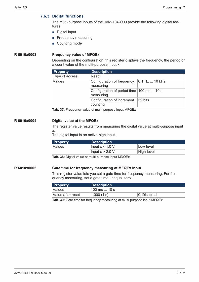
7.6.3 Digital functionsThe multi-purpose inputs of the JVM-104-O09 provide the following digital fea-tures:■ Digital input■ Frequency measuring■ Counting mode
R 6010x0003 Frequency value of MFQExDepending on the configuration, this register displays the frequency, the period ora count value of the multi-purpose input x.
Property DescriptionType of access ReadValues Configuration of frequency
measuring0.1 Hz ... 10 kHz
Configuration of period timemeasuring
100 ms ... 10 s
Configuration of incrementcounting
32 bits
Tab. 37: Frequency value of multi-purpose input MFQEx
R 6010x0004 Digital value at the MFQExThe register value results from measuring the digital value at multi-purpose inputx. The digital input is an active-high input.
Property DescriptionValues Input x < 1.0 V Low-level
Input x > 2.0 V High-levelTab. 38: Digital value at multi-purpose input MDQEx
R 6010x0005 Gate time for frequency measuring at MFQEx inputThis register value lets you set a gate time for frequency measuring. For fre-quency measuring, set a gate time unequal zero.
Property DescriptionValues 100 ms ... 10 sValue after reset 1,000 (1 s) 0: DisabledTab. 39: Gate time for frequency measuring at multi-purpose input MFQEx
Jetter AG Programming | 7
JVM-104-O09 User Manual 36 / 62
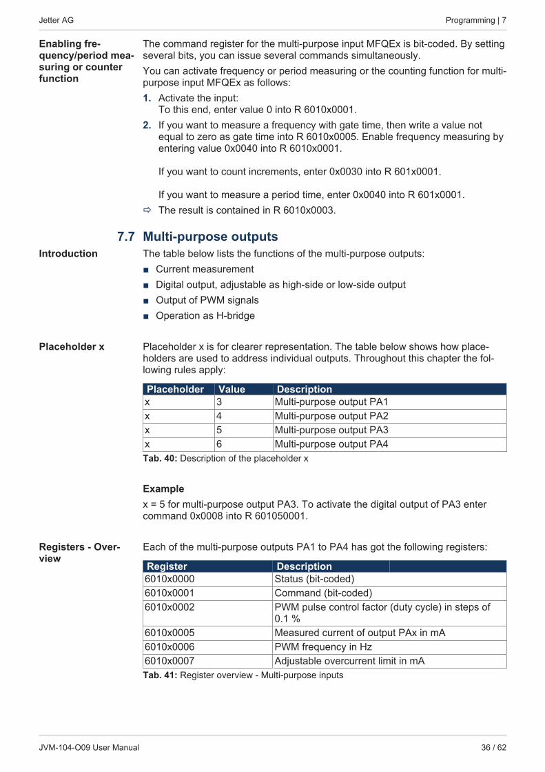
Enabling fre-quency/period mea-suring or counterfunction
The command register for the multi-purpose input MFQEx is bit-coded. By settingseveral bits, you can issue several commands simultaneously.You can activate frequency or period measuring or the counting function for multi-purpose input MFQEx as follows:1. Activate the input:
To this end, enter value 0 into R 6010x0001.2. If you want to measure a frequency with gate time, then write a value not
equal to zero as gate time into R 6010x0005. Enable frequency measuring byentering value 0x0040 into R 6010x0001.
If you want to count increments, enter 0x0030 into R 601x0001.
If you want to measure a period time, enter 0x0040 into R 601x0001.ð The result is contained in R 6010x0003.
7.7 Multi-purpose outputsIntroduction The table below lists the functions of the multi-purpose outputs:
■ Current measurement■ Digital output, adjustable as high-side or low-side output■ Output of PWM signals■ Operation as H-bridge
Placeholder x Placeholder x is for clearer representation. The table below shows how place-holders are used to address individual outputs. Throughout this chapter the fol-lowing rules apply:
Placeholder Value Descriptionx 3 Multi-purpose output PA1x 4 Multi-purpose output PA2x 5 Multi-purpose output PA3x 6 Multi-purpose output PA4Tab. 40: Description of the placeholder x
Examplex = 5 for multi-purpose output PA3. To activate the digital output of PA3 entercommand 0x0008 into R 601050001.
Registers - Over-view
Each of the multi-purpose outputs PA1 to PA4 has got the following registers:
Register Description6010x0000 Status (bit-coded)6010x0001 Command (bit-coded)6010x0002 PWM pulse control factor (duty cycle) in steps of
0.1 %6010x0005 Measured current of output PAx in mA6010x0006 PWM frequency in Hz6010x0007 Adjustable overcurrent limit in mATab. 41: Register overview - Multi-purpose inputs
Jetter AG Programming | 7
JVM-104-O09 User Manual 37 / 62
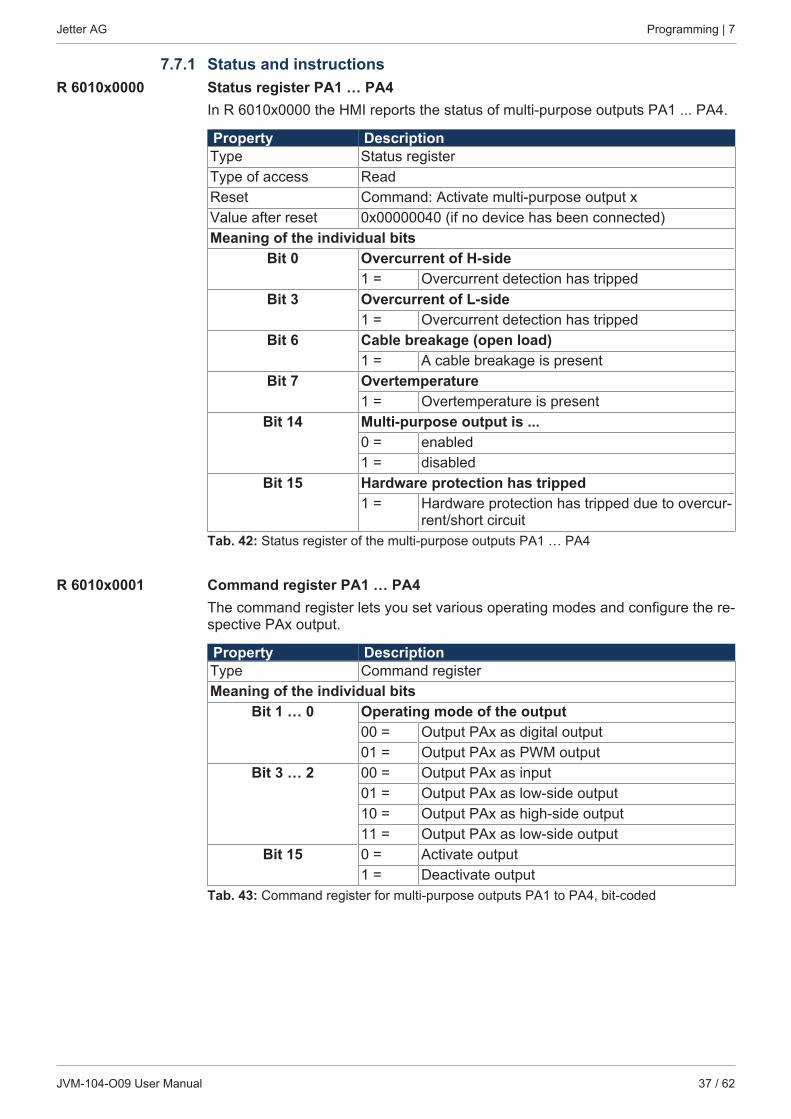
7.7.1 Status and instructionsR 6010x0000 Status register PA1 … PA4
In R 6010x0000 the HMI reports the status of multi-purpose outputs PA1 ... PA4.
Property DescriptionType Status registerType of access ReadReset Command: Activate multi-purpose output xValue after reset 0x00000040 (if no device has been connected)Meaning of the individual bits
Bit 0 Overcurrent of H-side1 = Overcurrent detection has tripped
Bit 3 Overcurrent of L-side1 = Overcurrent detection has tripped
Bit 6 Cable breakage (open load)1 = A cable breakage is present
Bit 7 Overtemperature1 = Overtemperature is present
Bit 14 Multi-purpose output is ...0 = enabled1 = disabled
Bit 15 Hardware protection has tripped1 = Hardware protection has tripped due to overcur-
rent/short circuitTab. 42: Status register of the multi-purpose outputs PA1 … PA4
R 6010x0001 Command register PA1 … PA4The command register lets you set various operating modes and configure the re-spective PAx output.
Property DescriptionType Command registerMeaning of the individual bits
Bit 1 … 0 Operating mode of the output00 = Output PAx as digital output01 = Output PAx as PWM output
Bit 3 … 2 00 = Output PAx as input01 = Output PAx as low-side output10 = Output PAx as high-side output11 = Output PAx as low-side output
Bit 15 0 = Activate output1 = Deactivate output
Tab. 43: Command register for multi-purpose outputs PA1 to PA4, bit-coded
Jetter AG Programming | 7
JVM-104-O09 User Manual 38 / 62
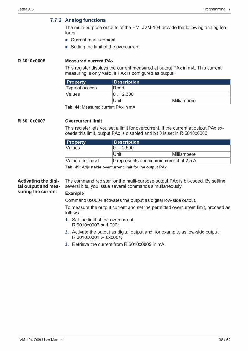
7.7.2 Analog functionsThe multi-purpose outputs of the HMI JVM-104 provide the following analog fea-tures:■ Current measurement■ Setting the limit of the overcurrent
R 6010x0005 Measured current PAxThis register displays the current measured at output PAx in mA. This currentmeasuring is only valid, if PAx is configured as output.
Property DescriptionType of access ReadValues 0 ... 2,300
Unit MilliampereTab. 44: Measured current PAx in mA
R 6010x0007 Overcurrent limitThis register lets you set a limit for overcurrent. If the current at output PAx ex-ceeds this limit, output PAx is disabled and bit 0 is set in R 6010x0000.
Property DescriptionValues 0 ... 2,500
Unit MilliampereValue after reset 0 represents a maximum current of 2.5 ATab. 45: Adjustable overcurrent limit for the output PAy
Activating the digi-tal output and mea-suring the current
The command register for the multi-purpose output PAx is bit-coded. By settingseveral bits, you issue several commands simultaneously.ExampleCommand 0x0004 activates the output as digital low-side output.To measure the output current and set the permitted overcurrent limit, proceed asfollows:1. Set the limit of the overcurrent:
R 6010x0007 := 1,000;2. Activate the output as digital output and, for example, as low-side output:
R 6010x0001 := 0x0004;3. Retrieve the current from R 6010x0005 in mA.
Jetter AG Programming | 7
JVM-104-O09 User Manual 39 / 62
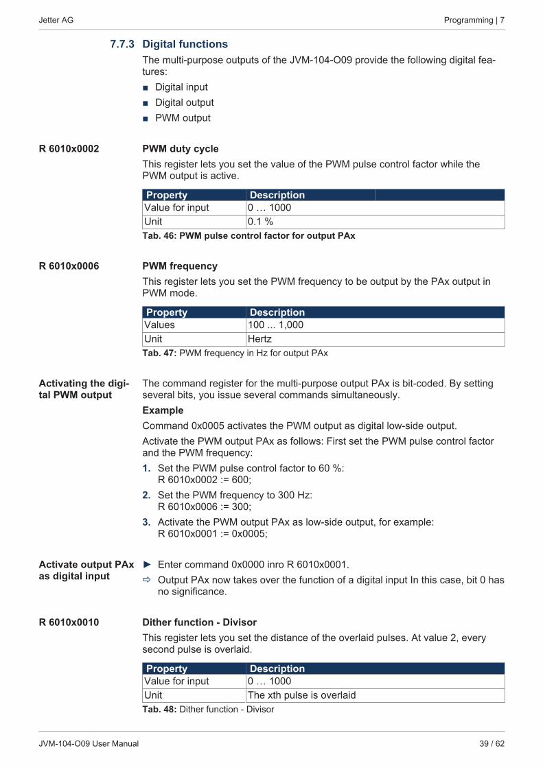
7.7.3 Digital functionsThe multi-purpose outputs of the JVM-104-O09 provide the following digital fea-tures:■ Digital input■ Digital output■ PWM output
R 6010x0002 PWM duty cycleThis register lets you set the value of the PWM pulse control factor while thePWM output is active.
Property DescriptionValue for input 0 … 1000Unit 0.1 %Tab. 46: PWM pulse control factor for output PAx
R 6010x0006 PWM frequencyThis register lets you set the PWM frequency to be output by the PAx output inPWM mode.
Property DescriptionValues 100 ... 1,000Unit HertzTab. 47: PWM frequency in Hz for output PAx
Activating the digi-tal PWM output
The command register for the multi-purpose output PAx is bit-coded. By settingseveral bits, you issue several commands simultaneously.ExampleCommand 0x0005 activates the PWM output as digital low-side output.Activate the PWM output PAx as follows: First set the PWM pulse control factorand the PWM frequency:1. Set the PWM pulse control factor to 60 %:
R 6010x0002 := 600;2. Set the PWM frequency to 300 Hz:
R 6010x0006 := 300;3. Activate the PWM output PAx as low-side output, for example:
R 6010x0001 := 0x0005;
Activate output PAxas digital input
► Enter command 0x0000 inro R 6010x0001.ð Output PAx now takes over the function of a digital input In this case, bit 0 has
no significance.
R 6010x0010 Dither function - DivisorThis register lets you set the distance of the overlaid pulses. At value 2, everysecond pulse is overlaid.
Property DescriptionValue for input 0 … 1000Unit The xth pulse is overlaidTab. 48: Dither function - Divisor
Jetter AG Programming | 7
JVM-104-O09 User Manual 40 / 62
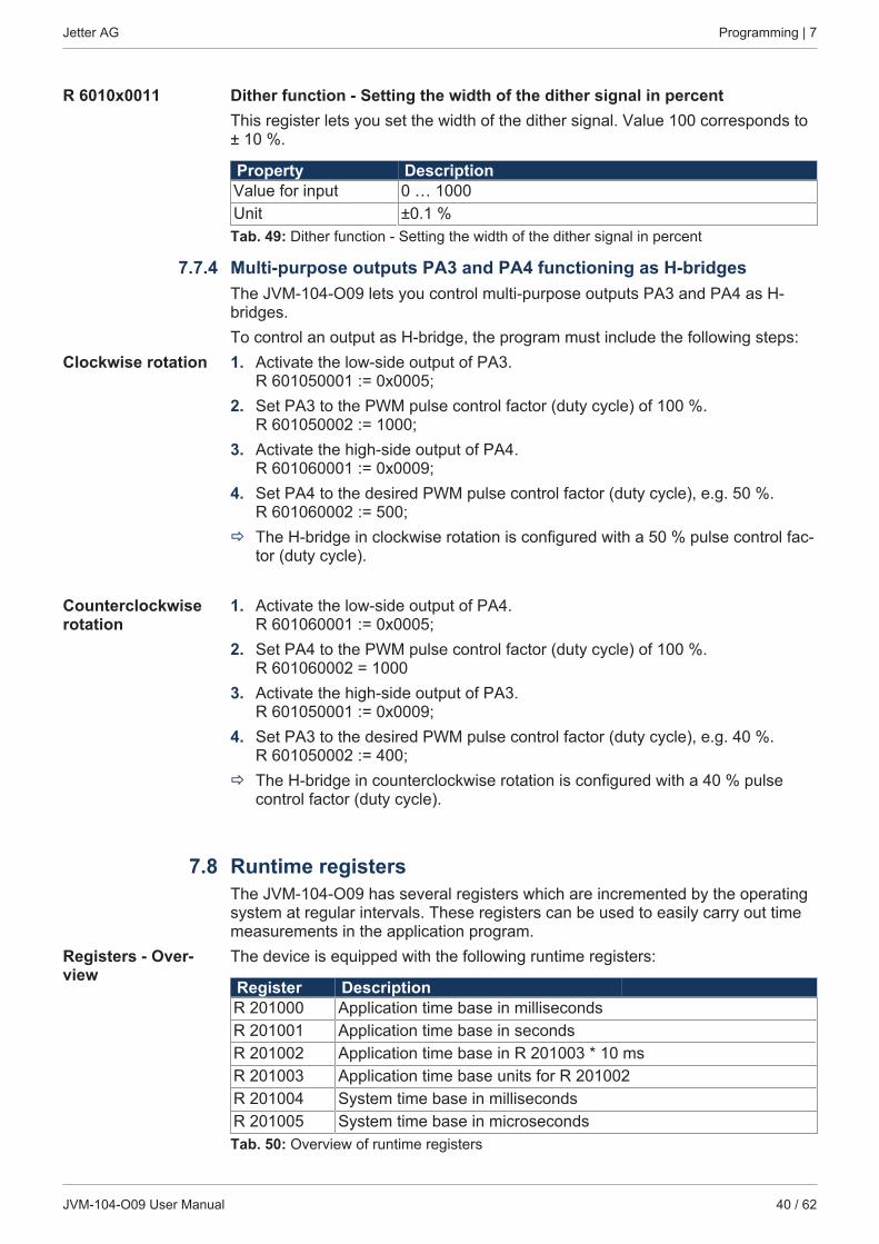
R 6010x0011 Dither function - Setting the width of the dither signal in percentThis register lets you set the width of the dither signal. Value 100 corresponds to± 10 %.
Property DescriptionValue for input 0 … 1000Unit ±0.1 %Tab. 49: Dither function - Setting the width of the dither signal in percent
7.7.4 Multi-purpose outputs PA3 and PA4 functioning as H-bridgesThe JVM-104-O09 lets you control multi-purpose outputs PA3 and PA4 as H-bridges.To control an output as H-bridge, the program must include the following steps:
Clockwise rotation 1. Activate the low-side output of PA3. R 601050001 := 0x0005;
2. Set PA3 to the PWM pulse control factor (duty cycle) of 100 %. R 601050002 := 1000;
3. Activate the high-side output of PA4. R 601060001 := 0x0009;
4. Set PA4 to the desired PWM pulse control factor (duty cycle), e.g. 50 %. R 601060002 := 500;
ð The H-bridge in clockwise rotation is configured with a 50 % pulse control fac-tor (duty cycle).
Counterclockwiserotation
1. Activate the low-side output of PA4. R 601060001 := 0x0005;
2. Set PA4 to the PWM pulse control factor (duty cycle) of 100 %. R 601060002 = 1000
3. Activate the high-side output of PA3. R 601050001 := 0x0009;
4. Set PA3 to the desired PWM pulse control factor (duty cycle), e.g. 40 %. R 601050002 := 400;
ð The H-bridge in counterclockwise rotation is configured with a 40 % pulsecontrol factor (duty cycle).
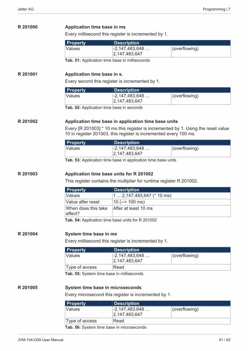
7.8 Runtime registersThe JVM-104-O09 has several registers which are incremented by the operatingsystem at regular intervals. These registers can be used to easily carry out timemeasurements in the application program.
Registers - Over-view
The device is equipped with the following runtime registers:
Register DescriptionR 201000 Application time base in millisecondsR 201001 Application time base in secondsR 201002 Application time base in R 201003 * 10 msR 201003 Application time base units for R 201002R 201004 System time base in millisecondsR 201005 System time base in microsecondsTab. 50: Overview of runtime registers
Jetter AG Programming | 7
JVM-104-O09 User Manual 41 / 62
R 201000 Application time base in msEvery millisecond this register is incremented by 1.
Property DescriptionValues -2,147,483,648 ...
2,147,483,647(overflowing)
Tab. 51: Application time base in milliseconds
R 201001 Application time base in s.Every second this register is incremented by 1.
Property DescriptionValues -2,147,483,648 ...
2,147,483,647(overflowing)
Tab. 52: Application time base in seconds
R 201002 Application time base in application time base unitsEvery [R 201003] * 10 ms this register is incremented by 1. Using the reset value10 in register 201003, this register is incremented every 100 ms.
Property DescriptionValues -2,147,483,648 ...
2,147,483,647(overflowing)
Tab. 53: Application time base in application time base units
R 201003 Application time base units for R 201002This register contains the multiplier for runtime register R 201002.
Property DescriptionValues 1 ... 2,147,483,647 (* 10 ms)Value after reset 10 (--> 100 ms)When does this takeeffect?
After at least 10 ms
Tab. 54: Application time base units for R 201002
R 201004 System time base in msEvery millisecond this register is incremented by 1.
Property DescriptionValues -2,147,483,648 ...
2,147,483,647(overflowing)
Type of access ReadTab. 55: System time base in milliseconds
R 201005 System time base in microsecondsEvery microsecond this register is incremented by 1.
Property DescriptionValues -2,147,483,648 ...
2,147,483,647(overflowing)
Type of access ReadTab. 56: System time base in microseconds
Jetter AG Programming | 7
JVM-104-O09 User Manual 42 / 62
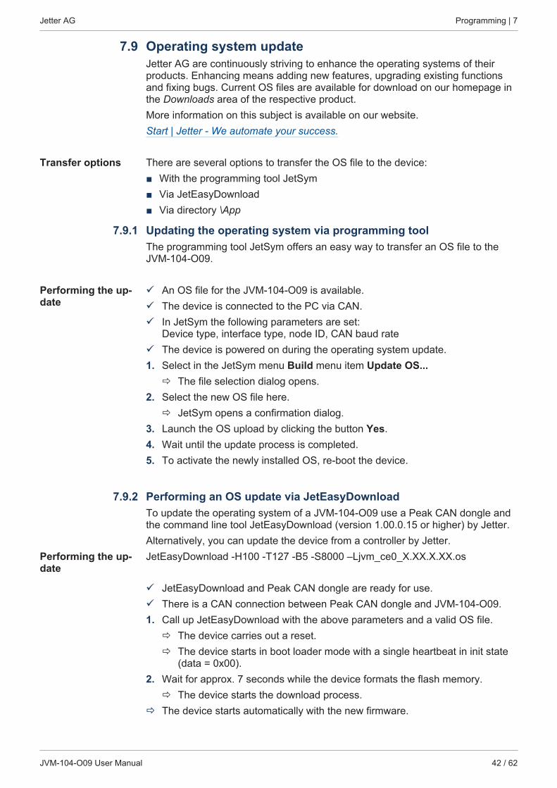
7.9 Operating system updateJetter AG are continuously striving to enhance the operating systems of theirproducts. Enhancing means adding new features, upgrading existing functionsand fixing bugs. Current OS files are available for download on our homepage inthe Downloads area of the respective product.More information on this subject is available on our website.Start | Jetter - We automate your success.
Transfer options There are several options to transfer the OS file to the device:■ With the programming tool JetSym■ Via JetEasyDownload■ Via directory \App
7.9.1 Updating the operating system via programming toolThe programming tool JetSym offers an easy way to transfer an OS file to theJVM-104-O09.
Performing the up-date
ü An OS file for the JVM-104-O09 is available.ü The device is connected to the PC via CAN.ü In JetSym the following parameters are set:
Device type, interface type, node ID, CAN baud rateü The device is powered on during the operating system update.1. Select in the JetSym menu Build menu item Update OS...
ð The file selection dialog opens.2. Select the new OS file here.
ð JetSym opens a confirmation dialog.3. Launch the OS upload by clicking the button Yes.4. Wait until the update process is completed.5. To activate the newly installed OS, re-boot the device.
7.9.2 Performing an OS update via JetEasyDownloadTo update the operating system of a JVM-104-O09 use a Peak CAN dongle andthe command line tool JetEasyDownload (version 1.00.0.15 or higher) by Jetter.Alternatively, you can update the device from a controller by Jetter.
Performing the up-date
JetEasyDownload -H100 -T127 -B5 -S8000 –Ljvm_ce0_X.XX.X.XX.os
ü JetEasyDownload and Peak CAN dongle are ready for use.ü There is a CAN connection between Peak CAN dongle and JVM-104-O09.1. Call up JetEasyDownload with the above parameters and a valid OS file.
ð The device carries out a reset.ð The device starts in boot loader mode with a single heartbeat in init state
(data = 0x00).2. Wait for approx. 7 seconds while the device formats the flash memory.
ð The device starts the download process.ð The device starts automatically with the new firmware.
Jetter AG Programming | 7
JVM-104-O09 User Manual 43 / 62
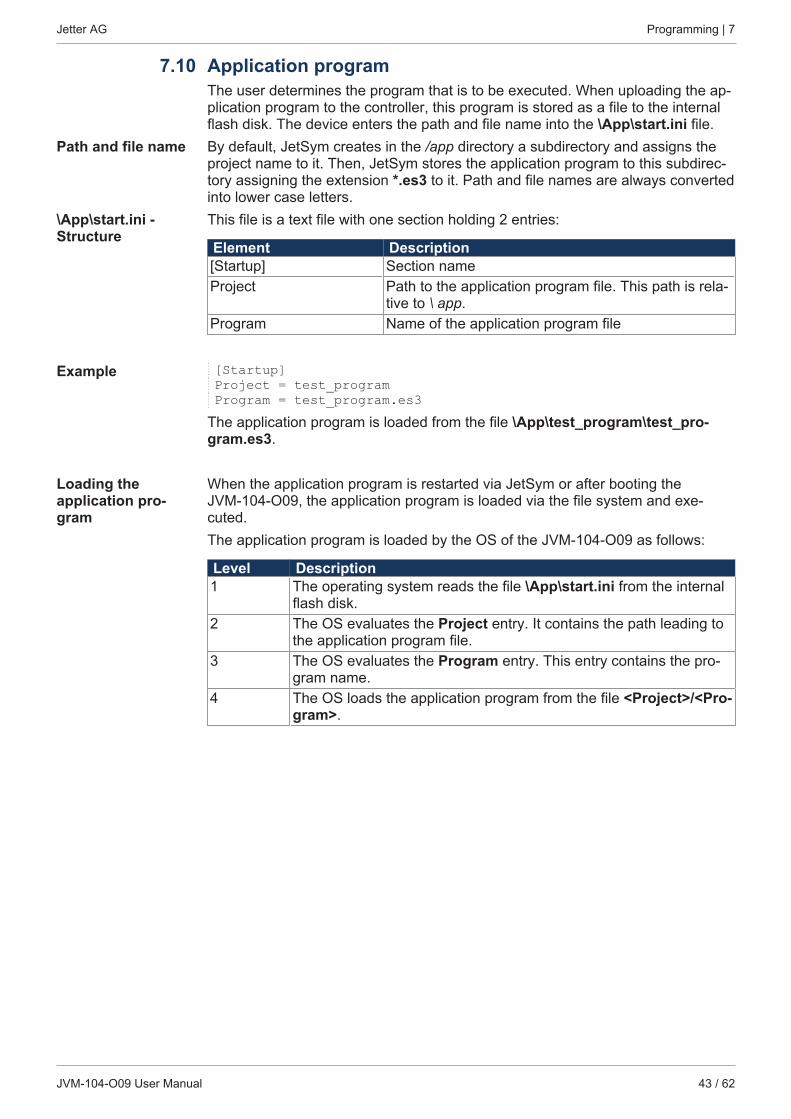
7.10 Application programThe user determines the program that is to be executed. When uploading the ap-plication program to the controller, this program is stored as a file to the internalflash disk. The device enters the path and file name into the \App\start.ini file.
Path and file name By default, JetSym creates in the /app directory a subdirectory and assigns theproject name to it. Then, JetSym stores the application program to this subdirec-tory assigning the extension *.es3 to it. Path and file names are always convertedinto lower case letters.
\App\start.ini -Structure
This file is a text file with one section holding 2 entries:
Element Description[Startup] Section nameProject Path to the application program file. This path is rela-
tive to \ app.Program Name of the application program file
Example [Startup]Project = test_programProgram = test_program.es3
The application program is loaded from the file \App\test_program\test_pro-gram.es3.
Loading the application pro-gram
When the application program is restarted via JetSym or after booting theJVM-104-O09, the application program is loaded via the file system and exe-cuted.The application program is loaded by the OS of the JVM-104-O09 as follows:
Level Description1 The operating system reads the file \App\start.ini from the internal
flash disk.2 The OS evaluates the Project entry. It contains the path leading to
the application program file.3 The OS evaluates the Program entry. This entry contains the pro-
gram name.4 The OS loads the application program from the file <Project>/<Pro-
gram>.
Jetter AG Registers - Overview | 8
JVM-104-O09 User Manual 44 / 62
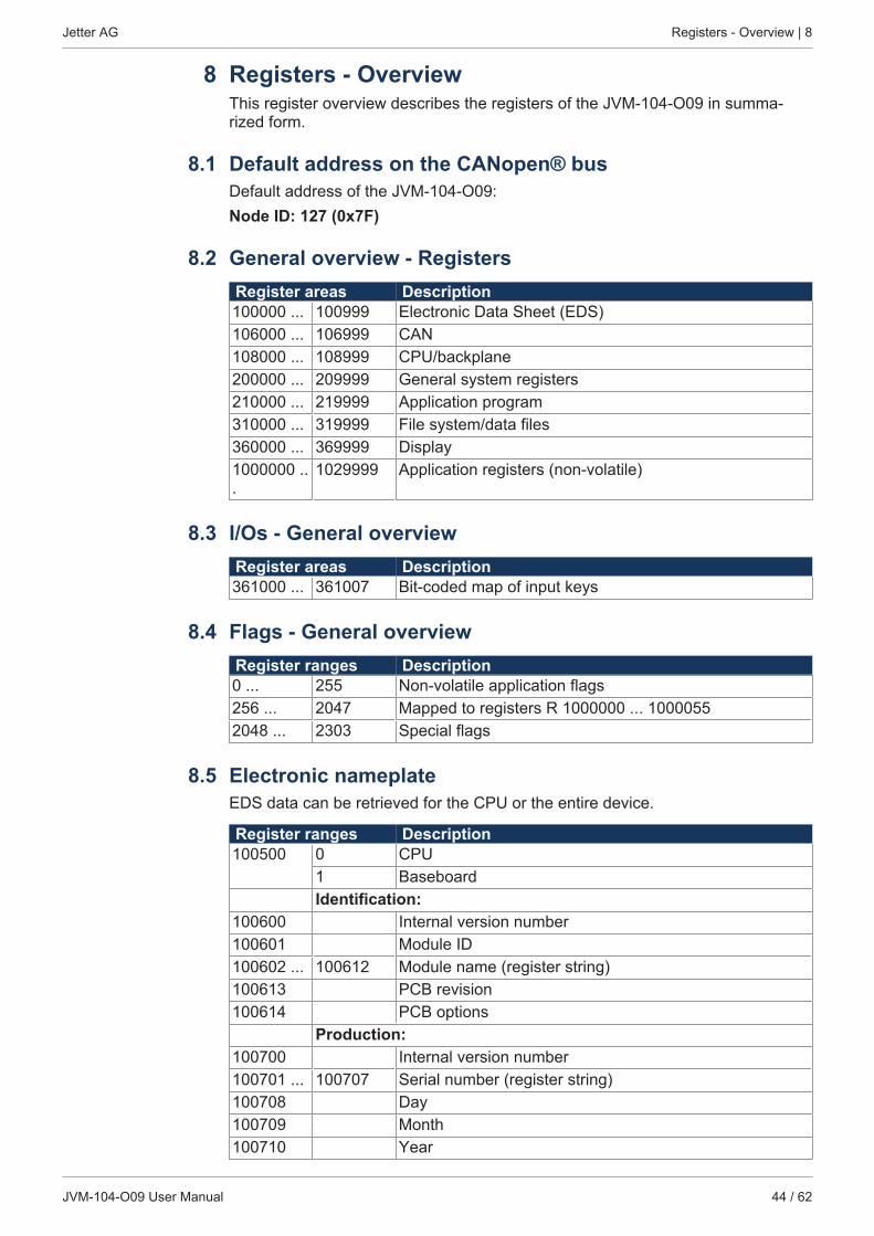
8 Registers - OverviewThis register overview describes the registers of the JVM-104-O09 in summa-rized form.
8.1 Default address on the CANopen® busDefault address of the JVM-104-O09:Node ID: 127 (0x7F)
8.2 General overview - RegistersRegister areas Description100000 ... 100999 Electronic Data Sheet (EDS)106000 ... 106999 CAN108000 ... 108999 CPU/backplane200000 ... 209999 General system registers210000 ... 219999 Application program310000 ... 319999 File system/data files360000 ... 369999 Display1000000 ...
1029999 Application registers (non-volatile)
8.3 I/Os - General overviewRegister areas Description361000 ... 361007 Bit-coded map of input keys
8.4 Flags - General overviewRegister ranges Description0 ... 255 Non-volatile application flags256 ... 2047 Mapped to registers R 1000000 ... 10000552048 ... 2303 Special flags
8.5 Electronic nameplateEDS data can be retrieved for the CPU or the entire device.
Register ranges Description100500 0 CPU
1 BaseboardIdentification:
100600 Internal version number100601 Module ID100602 ... 100612 Module name (register string)100613 PCB revision100614 PCB options
Production:100700 Internal version number100701 ... 100707 Serial number (register string)100708 Day100709 Month100710 Year
Jetter AG Registers - Overview | 8
JVM-104-O09 User Manual 45 / 62
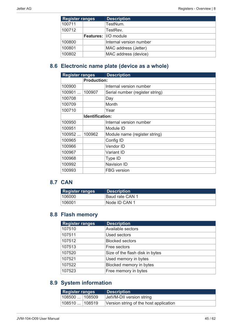
Register ranges Description100711 TestNum.100712 TestRev.
Features: I/O module100800 Internal version number100801 MAC address (Jetter)100802 MAC address (device)
8.6 Electronic name plate (device as a whole)Register ranges Description
Production:100900 Internal version number100901 ... 100907 Serial number (register string)100708 Day100709 Month100710 Year
Identification:100950 Internal version number100951 Module ID100952 ... 100962 Module name (register string)100965 Config ID100966 Vendor ID100967 Variant ID100968 Type ID100992 Navision ID100993 FBG version
8.7 CANRegister ranges Description106000 Baud rate CAN 1106001 Node ID CAN 1
8.8 Flash memoryRegister ranges Description107510 Available sectors107511 Used sectors107512 Blocked sectors107513 Free sectors107520 Size of the flash disk in bytes107521 Used memory in bytes107522 Blocked memory in bytes107523 Free memory in bytes
8.9 System informationRegister ranges Description108500 ... 108509 JetVM-DII version string108510 ... 108519 Version string of the host application
Jetter AG Registers - Overview | 8
JVM-104-O09 User Manual 46 / 62
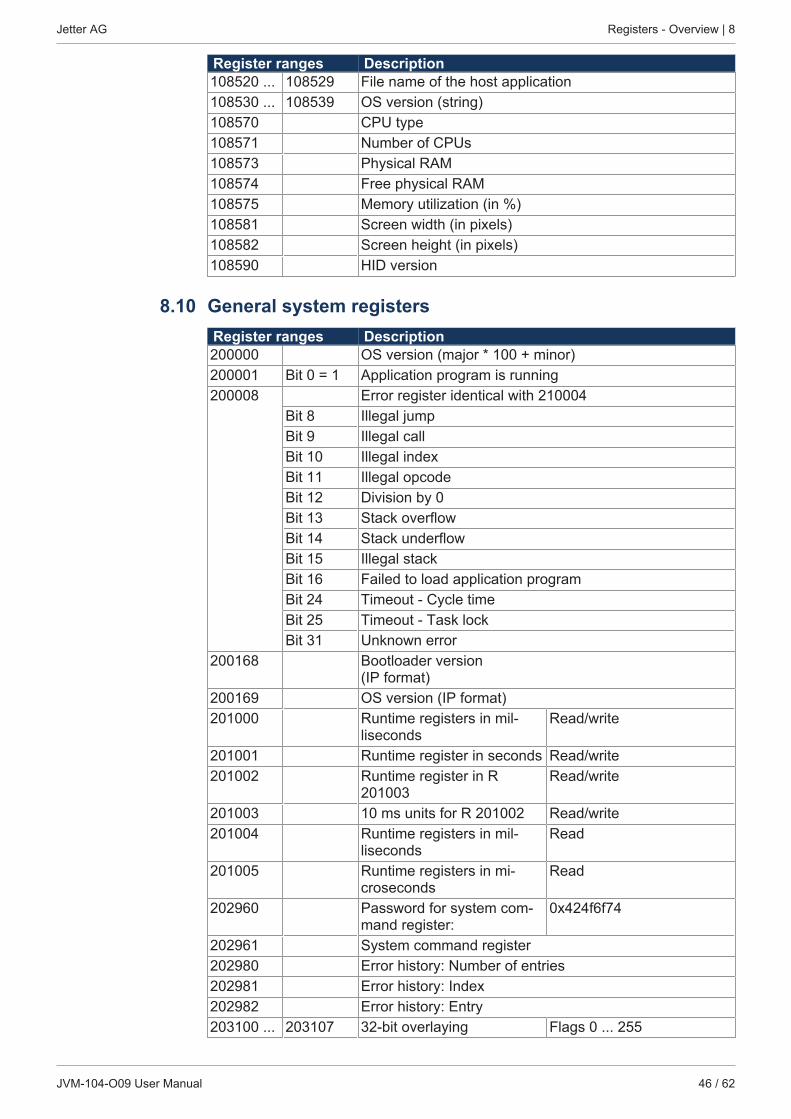
Register ranges Description108520 ... 108529 File name of the host application108530 ... 108539 OS version (string)108570 CPU type108571 Number of CPUs108573 Physical RAM108574 Free physical RAM108575 Memory utilization (in %)108581 Screen width (in pixels)108582 Screen height (in pixels)108590 HID version
8.10 General system registersRegister ranges Description200000 OS version (major * 100 + minor)200001 Bit 0 = 1 Application program is running200008 Error register identical with 210004
Bit 8 Illegal jumpBit 9 Illegal callBit 10 Illegal indexBit 11 Illegal opcodeBit 12 Division by 0Bit 13 Stack overflowBit 14 Stack underflowBit 15 Illegal stackBit 16 Failed to load application programBit 24 Timeout - Cycle timeBit 25 Timeout - Task lockBit 31 Unknown error
200168 Bootloader version(IP format)
200169 OS version (IP format)201000 Runtime registers in mil-
lisecondsRead/write
201001 Runtime register in seconds Read/write201002 Runtime register in R
201003Read/write
201003 10 ms units for R 201002 Read/write201004 Runtime registers in mil-
lisecondsRead
201005 Runtime registers in mi-croseconds
Read
202960 Password for system com-mand register:
0x424f6f74
202961 System command register202980 Error history: Number of entries202981 Error history: Index202982 Error history: Entry203100 ... 203107 32-bit overlaying Flags 0 ... 255
Jetter AG Registers - Overview | 8
JVM-104-O09 User Manual 47 / 62
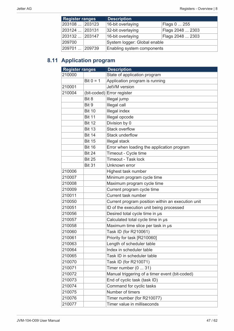
Register ranges Description203108 ... 203123 16-bit overlaying Flags 0 ... 255203124 ... 203131 32-bit overlaying Flags 2048 ... 2303203132 ... 203147 16-bit overlaying Flags 2048 ... 2303209700 System logger: Global enable209701 ... 209739 Enabling system components
8.11 Application programRegister ranges Description210000 State of application program
Bit 0 = 1 Application program is running210001 JetVM version210004 (bit-coded) Error register
Bit 8 Illegal jumpBit 9 Illegal callBit 10 Illegal indexBit 11 Illegal opcodeBit 12 Division by 0Bit 13 Stack overflowBit 14 Stack underflowBit 15 Illegal stackBit 16 Error when loading the application programBit 24 Timeout - Cycle timeBit 25 Timeout - Task lockBit 31 Unknown error
210006 Highest task number210007 Minimum program cycle time210008 Maximum program cycle time210009 Current program cycle time210011 Current task number210050 Current program position within an execution unit210051 ID of the execution unit being processed210056 Desired total cycle time in µs210057 Calculated total cycle time in µs210058 Maximum time slice per task in µs210060 Task ID (for R210061)210061 Priority for task [R210060]210063 Length of scheduler table210064 Index in scheduler table210065 Task ID in scheduler table210070 Task ID (for R210071)210071 Timer number (0 ... 31)210072 Manual triggering of a timer event (bit-coded)210073 End of cyclic task (task ID)210074 Command for cyclic tasks210075 Number of timers210076 Timer number (for R210077)210077 Timer value in milliseconds
Jetter AG Registers - Overview | 8
JVM-104-O09 User Manual 48 / 62
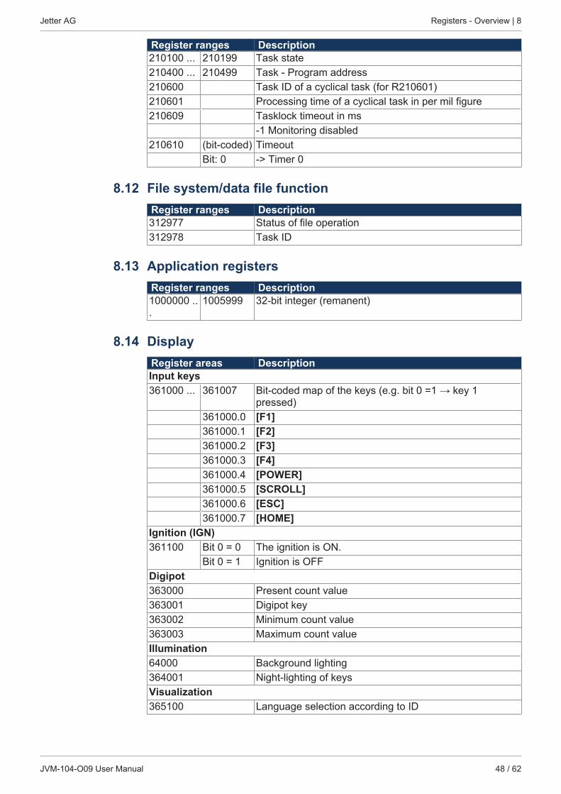
Register ranges Description210100 ... 210199 Task state210400 ... 210499 Task - Program address210600 Task ID of a cyclical task (for R210601)210601 Processing time of a cyclical task in per mil figure210609 Tasklock timeout in ms
-1 Monitoring disabled210610 (bit-coded) Timeout
Bit: 0 -> Timer 0
8.12 File system/data file functionRegister ranges Description312977 Status of file operation312978 Task ID
8.13 Application registersRegister ranges Description1000000 ...
1005999 32-bit integer (remanent)
8.14 DisplayRegister areas DescriptionInput keys361000 ... 361007 Bit-coded map of the keys (e.g. bit 0 =1 → key 1
pressed)361000.0 [F1]361000.1 [F2]361000.2 [F3]361000.3 [F4]361000.4 [POWER]361000.5 [SCROLL]361000.6 [ESC]361000.7 [HOME]
Ignition (IGN)361100 Bit 0 = 0 The ignition is ON.
Bit 0 = 1 Ignition is OFFDigipot363000 Present count value363001 Digipot key363002 Minimum count value363003 Maximum count valueIllumination64000 Background lighting364001 Night-lighting of keysVisualization365100 Language selection according to ID
Jetter AG Registers - Overview | 8
JVM-104-O09 User Manual 49 / 62
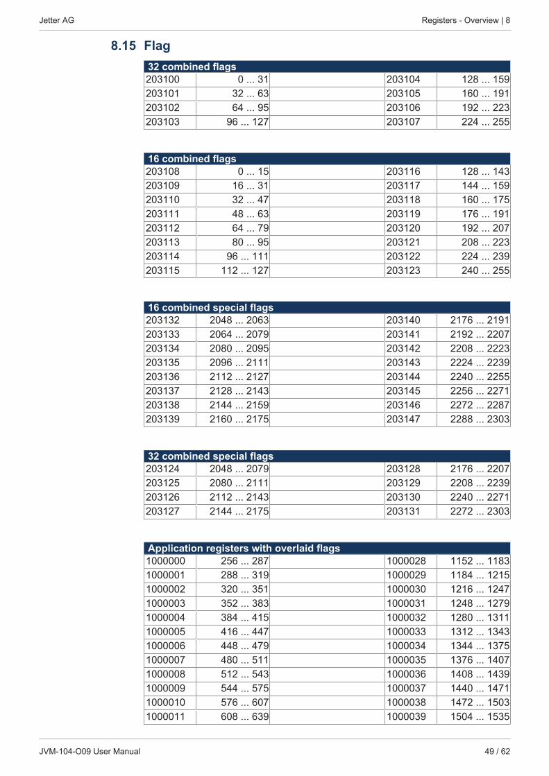
8.15 Flag32 combined flags203100 0 ... 31 203104 128 ... 159203101 32 ... 63 203105 160 ... 191203102 64 ... 95 203106 192 ... 223203103 96 ... 127 203107 224 ... 255
16 combined flags203108 0 ... 15 203116 128 ... 143203109 16 ... 31 203117 144 ... 159203110 32 ... 47 203118 160 ... 175203111 48 ... 63 203119 176 ... 191203112 64 ... 79 203120 192 ... 207203113 80 ... 95 203121 208 ... 223203114 96 ... 111 203122 224 ... 239203115 112 ... 127 203123 240 ... 255
16 combined special flags203132 2048 ... 2063 203140 2176 ... 2191203133 2064 ... 2079 203141 2192 ... 2207203134 2080 ... 2095 203142 2208 ... 2223203135 2096 ... 2111 203143 2224 ... 2239203136 2112 ... 2127 203144 2240 ... 2255203137 2128 ... 2143 203145 2256 ... 2271203138 2144 ... 2159 203146 2272 ... 2287203139 2160 ... 2175 203147 2288 ... 2303
32 combined special flags203124 2048 ... 2079 203128 2176 ... 2207203125 2080 ... 2111 203129 2208 ... 2239203126 2112 ... 2143 203130 2240 ... 2271203127 2144 ... 2175 203131 2272 ... 2303
Application registers with overlaid flags1000000 256 ... 287 1000028 1152 ... 11831000001 288 ... 319 1000029 1184 ... 12151000002 320 ... 351 1000030 1216 ... 12471000003 352 ... 383 1000031 1248 ... 12791000004 384 ... 415 1000032 1280 ... 13111000005 416 ... 447 1000033 1312 ... 13431000006 448 ... 479 1000034 1344 ... 13751000007 480 ... 511 1000035 1376 ... 14071000008 512 ... 543 1000036 1408 ... 14391000009 544 ... 575 1000037 1440 ... 14711000010 576 ... 607 1000038 1472 ... 15031000011 608 ... 639 1000039 1504 ... 1535
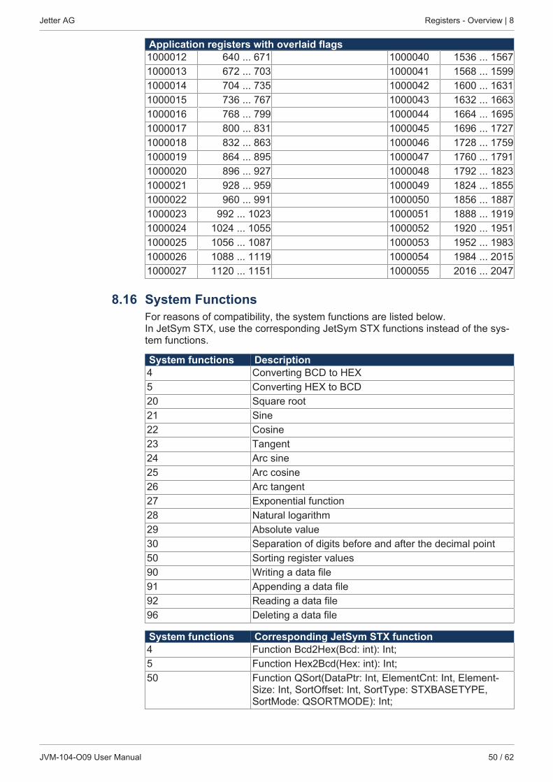
Jetter AG Registers - Overview | 8
JVM-104-O09 User Manual 50 / 62
Application registers with overlaid flags1000012 640 ... 671 1000040 1536 ... 15671000013 672 ... 703 1000041 1568 ... 15991000014 704 ... 735 1000042 1600 ... 16311000015 736 ... 767 1000043 1632 ... 16631000016 768 ... 799 1000044 1664 ... 16951000017 800 ... 831 1000045 1696 ... 17271000018 832 ... 863 1000046 1728 ... 17591000019 864 ... 895 1000047 1760 ... 17911000020 896 ... 927 1000048 1792 ... 18231000021 928 ... 959 1000049 1824 ... 18551000022 960 ... 991 1000050 1856 ... 18871000023 992 ... 1023 1000051 1888 ... 19191000024 1024 ... 1055 1000052 1920 ... 19511000025 1056 ... 1087 1000053 1952 ... 19831000026 1088 ... 1119 1000054 1984 ... 20151000027 1120 ... 1151 1000055 2016 ... 2047
8.16 System FunctionsFor reasons of compatibility, the system functions are listed below.In JetSym STX, use the corresponding JetSym STX functions instead of the sys-tem functions.
System functions Description4 Converting BCD to HEX5 Converting HEX to BCD20 Square root21 Sine22 Cosine23 Tangent24 Arc sine25 Arc cosine26 Arc tangent27 Exponential function28 Natural logarithm29 Absolute value30 Separation of digits before and after the decimal point50 Sorting register values90 Writing a data file91 Appending a data file92 Reading a data file96 Deleting a data file
System functions Corresponding JetSym STX function4 Function Bcd2Hex(Bcd: int): Int;5 Function Hex2Bcd(Hex: int): Int;50 Function QSort(DataPtr: Int, ElementCnt: Int, Element-
Size: Int, SortOffset: Int, SortType: STXBASETYPE,SortMode: QSORTMODE): Int;

Jetter AG Registers - Overview | 8
JVM-104-O09 User Manual 51 / 62
System functions Corresponding JetSym STX function90/91 Function FileDAWrite(Const Ref FileName: String, Const
Ref Mode: String, VarType: DAWRITE_TYPE, First: Int,Last: int): Int;
92 Function FileDARead(Const Ref FileName: String): Int;
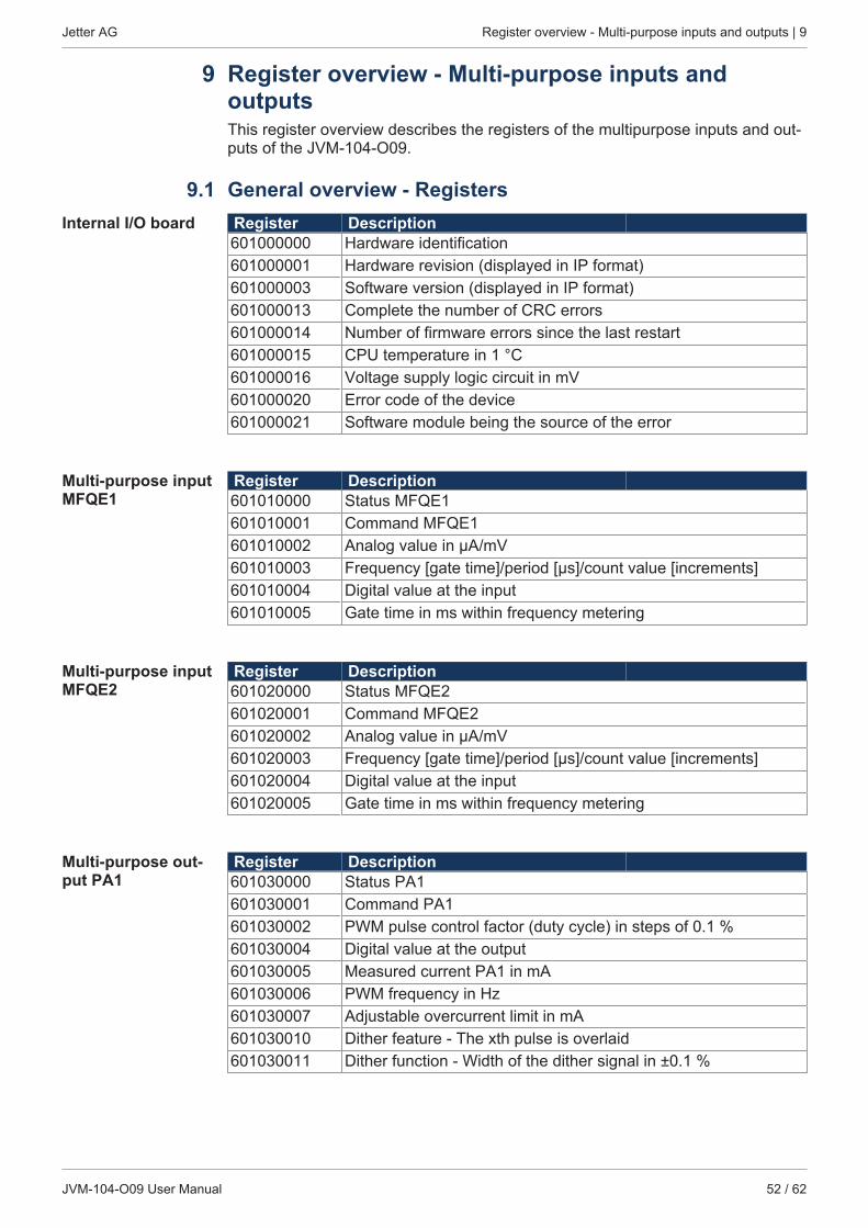
Jetter AG Register overview - Multi-purpose inputs and outputs | 9
JVM-104-O09 User Manual 52 / 62
9 Register overview - Multi-purpose inputs andoutputsThis register overview describes the registers of the multipurpose inputs and out-puts of the JVM-104-O09.
9.1 General overview - RegistersInternal I/O board Register Description
601000000 Hardware identification601000001 Hardware revision (displayed in IP format)601000003 Software version (displayed in IP format)601000013 Complete the number of CRC errors601000014 Number of firmware errors since the last restart601000015 CPU temperature in 1 °C601000016 Voltage supply logic circuit in mV601000020 Error code of the device601000021 Software module being the source of the error
Multi-purpose inputMFQE1
Register Description601010000 Status MFQE1601010001 Command MFQE1601010002 Analog value in µA/mV601010003 Frequency [gate time]/period [μs]/count value [increments]601010004 Digital value at the input601010005 Gate time in ms within frequency metering
Multi-purpose inputMFQE2
Register Description601020000 Status MFQE2601020001 Command MFQE2601020002 Analog value in µA/mV601020003 Frequency [gate time]/period [μs]/count value [increments]601020004 Digital value at the input601020005 Gate time in ms within frequency metering
Multi-purpose out-put PA1
Register Description601030000 Status PA1601030001 Command PA1601030002 PWM pulse control factor (duty cycle) in steps of 0.1 %601030004 Digital value at the output601030005 Measured current PA1 in mA601030006 PWM frequency in Hz601030007 Adjustable overcurrent limit in mA601030010 Dither feature - The xth pulse is overlaid601030011 Dither function - Width of the dither signal in ±0.1 %
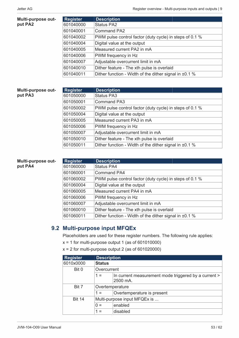
Jetter AG Register overview - Multi-purpose inputs and outputs | 9
JVM-104-O09 User Manual 53 / 62
Multi-purpose out-put PA2
Register Description601040000 Status PA2601040001 Command PA2601040002 PWM pulse control factor (duty cycle) in steps of 0.1 %601040004 Digital value at the output601040005 Measured current PA2 in mA601040006 PWM frequency in Hz601040007 Adjustable overcurrent limit in mA601040010 Dither feature - The xth pulse is overlaid601040011 Dither function - Width of the dither signal in ±0.1 %
Multi-purpose out-put PA3
Register Description601050000 Status PA3601050001 Command PA3601050002 PWM pulse control factor (duty cycle) in steps of 0.1 %601050004 Digital value at the output601050005 Measured current PA3 in mA601050006 PWM frequency in Hz601050007 Adjustable overcurrent limit in mA601050010 Dither feature - The xth pulse is overlaid601050011 Dither function - Width of the dither signal in ±0.1 %
Multi-purpose out-put PA4
Register Description601060000 Status PA4601060001 Command PA4601060002 PWM pulse control factor (duty cycle) in steps of 0.1 %601060004 Digital value at the output601060005 Measured current PA4 in mA601060006 PWM frequency in Hz601060007 Adjustable overcurrent limit in mA601060010 Dither feature - The xth pulse is overlaid601060011 Dither function - Width of the dither signal in ±0.1 %
9.2 Multi-purpose input MFQExPlaceholders are used for these register numbers. The following rule applies:x = 1 for multi-purpose output 1 (as of 601010000)x = 2 for multi-purpose output 2 (as of 601020000)
Register Description6010x0000 Status
Bit 0 Overcurrent1 = In current measurement mode triggered by a current >
2500 mA.Bit 7 Overtemperature
1 = Overtemperature is presentBit 14 Multi-purpose input MFQEx is ...
0 = enabled1 = disabled
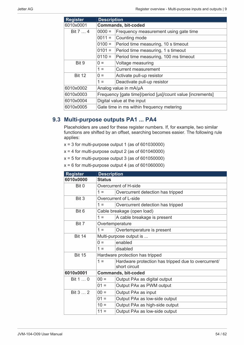
Jetter AG Register overview - Multi-purpose inputs and outputs | 9
JVM-104-O09 User Manual 54 / 62
Register Description6010x0001 Commands, bit-coded
Bit 7 … 4 0000 = Frequency measurement using gate time0011 = Counting mode0100 = Period time measuring, 10 s timeout0101 = Period time measuring, 1 s timeout0110 = Period time measuring, 100 ms timeout
Bit 9 0 = Voltage measuring1 = Current measurement
Bit 12 0 = Activate pull-up resistor1 = Deactivate pull-up resistor
6010x0002 Analog value in mA/µA6010x0003 Frequency [gate time]/period [μs]/count value [increments]6010x0004 Digital value at the input6010x0005 Gate time in ms within frequency metering
9.3 Multi-purpose outputs PA1 ... PA4Placeholders are used for these register numbers. If, for example, two similarfunctions are shifted by an offset, searching becomes easier. The following ruleapplies:x = 3 for multi-purpose output 1 (as of 601030000)x = 4 for multi-purpose output 2 (as of 601040000)x = 5 for multi-purpose output 3 (as of 601050000)x = 6 for multi-purpose output 4 (as of 601060000)
Register Description6010x0000 Status
Bit 0 Overcurrent of H-side1 = Overcurrent detection has tripped
Bit 3 Overcurrent of L-side1 = Overcurrent detection has tripped
Bit 6 Cable breakage (open load)1 = A cable breakage is present
Bit 7 Overtemperature1 = Overtemperature is present
Bit 14 Multi-purpose output is ...0 = enabled1 = disabled
Bit 15 Hardware protection has tripped1 = Hardware protection has tripped due to overcurrent/
short circuit6010x0001 Commands, bit-coded
Bit 1 … 0 00 = Output PAx as digital output01 = Output PAx as PWM output
Bit 3 … 2 00 = Output PAx as input01 = Output PAx as low-side output10 = Output PAx as high-side output11 = Output PAx as low-side output
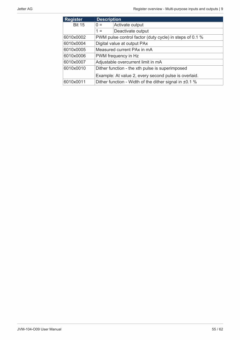
Jetter AG Register overview - Multi-purpose inputs and outputs | 9
JVM-104-O09 User Manual 55 / 62
Register DescriptionBit 15 0 = Activate output
1 = Deactivate output6010x0002 PWM pulse control factor (duty cycle) in steps of 0.1 %6010x0004 Digital value at output PAx6010x0005 Measured current PAx in mA6010x0006 PWM frequency in Hz6010x0007 Adjustable overcurrent limit in mA6010x0010 Dither function - the xth pulse is superimposed
Example: At value 2, every second pulse is overlaid.6010x0011 Dither function - Width of the dither signal in ±0.1 %

Jetter AG Maintenance and repairs | 10
JVM-104-O09 User Manual 56 / 62
10 Maintenance and repairs
10.1 Maintenance, repairs and disposalMaintenance This device is maintenance-free.
Therefore, for the operation of the device no inspection or maintenance are re-quired.
Repairs Defective components could cause dangerous malfunctions and could compro-mise safety.Only the manufacturer is allowed to repair the device. Do not open the device!
Disposal of obso-lete equipment
The device must be disposed of in accordance with the Environmental ProductDeclaration EPD. Applicable local environmental directives and regulations mustbe complied with. This product must be disposed of as waste electronic equip-ment. Waste packaging material must be recycled or reused.
Modifications andalterations to thedevice
Modifications and alterations to the device and its functions are not allowed. Inthe case of modifications to the device, any liability is excluded.The original parts are specifically designed for the device. Parts and equipmentfrom other manufacturers must, therefore, not be used.Any liability for any damages resulting from the use of non-original parts andequipment is excluded.
10.2 Storage and shipmentStorage When storing the device observe the environmental conditions given in chapter
“Technical specifications”.Shipment and pack-aging
The device contains electrostatically sensitive components which can be dam-aged if not handled properly. Damages to the device may impair its reliability.To protect the device from impact or shock, it must be shipped in its originalpackaging, or in an appropriate protective ESD packaging.In case of damaged packaging inspect the device for any visible damage, and in-form your freight forwarder and the Jetter AG of the damage caused during ship-ment. If the device is damaged or has been dropped, it is strictly forbidden to useit.

Jetter AG Service | 11
JVM-104-O09 User Manual 57 / 62
11 Service
11.1 Customer serviceShould you have any questions, suggestions, or problems, please don’t hesitateto contact our service representatives. To contact them, please call our technicalhotline or use the contact form on our homepage:Technical hotline | Jetter - We automate your success.
You are also welcome to send an e-mail to our technical hotline:[email protected]
Please supply the following information when contacting our technical hotline:■ Hardware revision and serial number
For the hardware revision number, please refer to the nameplate.■ OS version
To determine the operating system version, use the functions of the develop-ment environment.
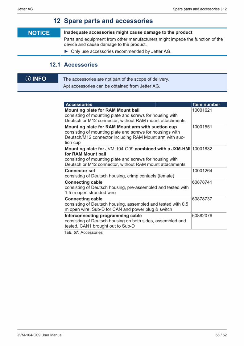
Jetter AG Spare parts and accessories | 12
JVM-104-O09 User Manual 58 / 62
12 Spare parts and accessories
NOTICE Inadequate accessories might cause damage to the productParts and equipment from other manufacturers might impede the function of thedevice and cause damage to the product.► Only use accessories recommended by Jetter AG.
12.1 Accessories
INFO The accessories are not part of the scope of delivery.Apt accessories can be obtained from Jetter AG.
Accessories Item numberMounting plate for RAM Mount ball consisting of mounting plate and screws for housing withDeutsch or M12 connector, without RAM mount attachments
10001621
Mounting plate for RAM Mount arm with suction cup consisting of mounting plate and screws for housings withDeutsch/M12 connector including RAM Mount arm with suc-tion cup
10001551
Mounting plate for JVM-104-O09 combined with a JXM-HMIfor RAM Mount ballconsisting of mounting plate and screws for housing withDeutsch or M12 connector, without RAM mount attachments
10001832
Connector setconsisting of Deutsch housing, crimp contacts (female)
10001264
Connecting cableconsisting of Deutsch housing, pre-assembled and tested with1.5 m open stranded wire
60878741
Connecting cable consisting of Deutsch housing, assembled and tested with 0.5m open wire, Sub-D for CAN and power plug & switch
60878737
Interconnecting programming cableconsisting of Deutsch housing on both sides, assembled andtested, CAN1 brought out to Sub-D
60882076
Tab. 57: Accessories
Jetter AG List of figures
JVM-104-O09 User Manual 59 / 62
List of figuresFig. 1 Device configuration................................................................................................................ 8Fig. 2 Nameplate ............................................................................................................................... 9Fig. 3 Dimensions (in mm) ................................................................................................................ 10Fig. 4 Space requirements for installation work (in mm) ................................................................... 16Fig. 5 All dimensions of screw holes are in millimeters. .................................................................... 17Fig. 6 Installation drawing.................................................................................................................. 18Fig. 7 Installing the strain relief.......................................................................................................... 18Fig. 8 Installation drawing.................................................................................................................. 19Fig. 9 Installing the strain relief.......................................................................................................... 20Fig. 10 Deutsch connector, 12 pins..................................................................................................... 22Fig. 11 H-bridges................................................................................................................................. 22Fig. 12 Wiring - Example ..................................................................................................................... 23
Jetter AG List of tables
JVM-104-O09 User Manual 60 / 62
List of tablesTab. 1 Power supply VBAT_ECU....................................................................................................... 10Tab. 2 Mechanical specifications........................................................................................................ 10Tab. 3 Environmental conditions ........................................................................................................ 11Tab. 4 Technical data - Display .......................................................................................................... 11Tab. 5 Acoustic signal generator ........................................................................................................ 11Tab. 6 CAN interface specification ..................................................................................................... 11Tab. 7 Specification - CAN bus cable................................................................................................. 12Tab. 8 Line lengths ............................................................................................................................. 12Tab. 9 Technical data - Power supply VBAT_PA............................................................................... 12Tab. 10 Technical Data – Digital Inputs MFQE .................................................................................... 12Tab. 11 Technical data - Voltage measurement................................................................................... 12Tab. 12 Technical data - Current measurement................................................................................... 12Tab. 13 Technical data - Frequency measurement.............................................................................. 13Tab. 14 Technical data - Counting function.......................................................................................... 13Tab. 15 Technical data - Digital input PAx ........................................................................................... 13Tab. 16 Technical data – Digital output ................................................................................................ 13Tab. 17 Technical data – PWM output ................................................................................................. 14Tab. 18 Technical data – H-bridge ....................................................................................................... 14Tab. 19 Pulses to ISO 7637-2 .............................................................................................................. 14Tab. 20 Irradiation to ISO 11452 .......................................................................................................... 15Tab. 21 ESD EN 61000-4-2.................................................................................................................. 15Tab. 22 Unsuitable installation locations .............................................................................................. 16Tab. 23 Mounting accessories.............................................................................................................. 17Tab. 24 Mounting accessories.............................................................................................................. 19Tab. 25 Abbreviations........................................................................................................................... 24Tab. 26 Module register properties....................................................................................................... 24Tab. 27 Numerical formats ................................................................................................................... 24Tab. 28 JetSym sample programs........................................................................................................ 24Tab. 29 Flash disk capacity .................................................................................................................. 28Tab. 30 Input key registers ................................................................................................................... 29Tab. 31 Virtual key codes ..................................................................................................................... 29Tab. 32 Description of the placeholder x .............................................................................................. 32Tab. 33 Register overview - Multi-purpose inputs ................................................................................ 32Tab. 34 Status register of the multi-purpose input MFQEx .................................................................. 33Tab. 35 Command register for multi-purpose input MFQEx, bit-coded ................................................ 33Tab. 36 Analog value of multi-purpose input MFQEx........................................................................... 34Tab. 37 Frequency value of multi-purpose input MFQEx ..................................................................... 35Tab. 38 Digital value at multi-purpose input MDQEx............................................................................ 35Tab. 39 Gate time for frequency measuring at multi-purpose input MFQEx ........................................ 35Tab. 40 Description of the placeholder x .............................................................................................. 36Tab. 41 Register overview - Multi-purpose inputs ................................................................................ 36Tab. 42 Status register of the multi-purpose outputs PA1 … PA4 ....................................................... 37Tab. 43 Command register for multi-purpose outputs PA1 to PA4, bit-coded...................................... 37
Jetter AG List of tables
JVM-104-O09 User Manual 61 / 62
Tab. 44 Measured current PAx in mA .................................................................................................. 38Tab. 45 Adjustable overcurrent limit for the output PAy ....................................................................... 38Tab. 46 PWM pulse control factor for output PAx ................................................................................ 39Tab. 47 PWM frequency in Hz for output PAx...................................................................................... 39Tab. 48 Dither function - Divisor ........................................................................................................... 39Tab. 49 Dither function - Setting the width of the dither signal in percent ............................................ 40Tab. 50 Overview of runtime registers.................................................................................................. 40Tab. 51 Application time base in milliseconds...................................................................................... 41Tab. 52 Application time base in seconds ............................................................................................ 41Tab. 53 Application time base in application time base units ............................................................... 41Tab. 54 Application time base units for R 201002................................................................................ 41Tab. 55 System time base in milliseconds ........................................................................................... 41Tab. 56 System time base in microseconds......................................................................................... 41Tab. 57 Accessories ............................................................................................................................. 58

6088
4730
We automate your success.
Jetter AGGraeterstrasse 271642 Ludwigsburgwww.jetter.de
E-mail [email protected] +49 7141 2550-0