Embed Size (px)
Citation preview

SUPER DIGIFINE HI-FI COMPONENTS
FX-101 COMPU -co TR ED
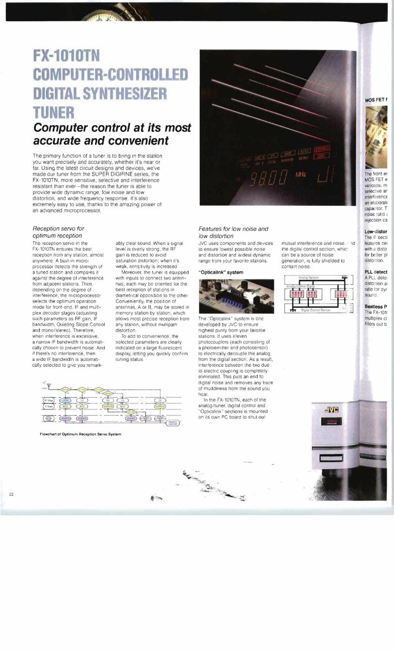
IGI lL Y T ESIZER T R Computer control at its most accurate and convenient The primary function of a tuner is to bring in the station you want precisely and accurately whether ii s near or far Using the latest circuit designs and devices weve made our tuner from the SUPER DIGIFINE series the FX-1010TN more sensitive selective and interference resistant than ever- the reason the tuner is able to provide wide dynamic range low noise and low distortion and wide frequency response Its also extremely easy to use thanks to the amazing power of an advanced microprocessor
Reception servo for optimum reception The recept ion servo in the ably clear sound When a signal FX-1010TN ensures the best level is overly strong the RF reception from any station almost gain is reduced to avoid anywhere A bUilt-in microshy saturation distortion when its processor detects the strength of weak sensitivity is increased a tuned station and compares it Moreover the tuner is equipped against the degree of Interference with inputs to connect two antenshyfrom adjacent stations Then nas each may be orienled for the depending on the degree of best reception of stations in interference the microprocessor diametrical opposition to the other selects the optimum operation Conveniently the position of mode for front-end IF and multishy antennas A or S may be stored in plex decoder stages (adjusting memory slation by station wh ich such parameters as RF gain IF allows most precise reception from bandwidth Quieting Slope Control any sta ti on wilhout multipath and monoste reo) Therefore distortion when Interference is exceSSive To add to convenience the a narrow IF bandwidth is aulomat lshy selected paramelers are clearly cally chosen to prevent nOise And indlcaled on a large fluorescen t if theres no interference then display le lling you quickly confirm a wide IF bandwidth is automatishy tuning status cally selected to give you remark-
Flowchart 01 Optimum Reception Servo System
varicaps m selective ar interferencE an elaboratJ capaCItor T noise ratio I
rejection ca
Features for low noise and Low-dlstor low distortion The IF secti JVC uses components and devices mutual interference and nOise middotd featu res cel to ensure lowest possible noise the digital control section whiG with a dlsto and distortion and widest dynamic can be 8 source of noise for b tier pi range from your favorite stations generation is fully shielded 10 distorTi on
contain noise Opticallnk system PLL detect
A PLL dete dlstol lion 81
ratio f r dyr sound
Beatfess P The FX-1011
The Opt icalink system is one mult iplex ci developed by JVC to ensure lilters out b highest pUrity from your lavorile slat ions It uses eleven photocouplers (each consisting of a photoemilier and photosensor) to electrically decouple the analog from fhe digital section As a result interference between the two due to elecfrlc coupt lng is completel y eliminated This puts an end to digital noise and removes any trace of muddiness from the sound you hear
In the FX-1010TN each of the analogtuner digital control and Optlcalink sections is mounted on its own PC board to shut oul
22
Inside view Of the FX-1010TN
I nOise And ln whicll e Ided to
varica ~ makes It as sensitive select e and resistant to interiE lt nce as a front end using an ela orate 5-ganged tuning capac f Therefore the slgnal-toshynoise tio and Interierenceshyrejectrn capability are outstand ing
Low- i tortlon IF section The II ectlon of the FX-1010TN featur 3 ceramic filters coupled with a middot1 tortion reduction circuit lor be -r phase response and low distor i)n
PLL elector A PLL letector combines low distor l n and high signal-to-noise ratio fr ynamic and wide-range sounc
Beatle1s PLL multiplex circuit The F 1010TN uses a new PLL multip bull circuit that electrically lilters II beat nOise-noise
resulting from two or more frequencies interfering with one another In a convenlional CR-Iype MPX circuit using a VCO (VoltageshyControlled Oscillalor) however a device called an anll-birdie filter is used 10 remove beat noise but the coils in the circuit tend to degrade Signal quality In our beatless multiplex CIrcuit moreover a pilot canceller is featured to suppress the leakage of the pilot signal thus obviating the need for a 19kHz filter another component that would harm sound qualily
Active filter To prevent leakage of Ihe 38kHz subcarrier contained in a stereo broadcast an LC filter built from coils and capaCitors IS commonly used but due 10 Ihe magnetic distorlion the core of Ihe cOil causes this system tends to degrade sound quality In the FX-l0l0TN however an acllve filter has replaced the passive LC filter with cOils ehmlnaled il provides better high-frequency response wider separation and higher signal-to-noise ratio
Computer-controlled operating ease With the help of poweriul microcomputers weve also improved tuning ease 01 the FX-l01OTN Iremendously
Station name display You can assign up to six alphanumeric characters to each presel station In the memoryshyJAZZ-8 lor instance
Auto memory All 40 FMIAM stations can be automatically tuned in sequence and committed 10 memory as presets
Random preset memory You can preset as many as 40 FMI AM stations in random order Theres a numeric keypad that allows direct access to any of 40 stations
Preset scan All preset FM IAM slations can be automatically sampled one by one for approximately 5 seconds each
Preset cancel Use this feature to skip undesired preset stations during preset scan
Program memory Up to eight events (broadcasts) can be programmed for sequential recall under the control of an optional timer
AutoQSC The Auto Quieting Slope Control Circuit automatically goes Into action to reduce noise when a station signal is weak
dB-referenced signal strength Indicator Read off the signal strength of a tuned station accurately down to 1dB-a convenience when orienting antennas
Variable stop level Adjust FMI AM muting threshold in 5dB steps over a range during auto tuning The variable stop level feature lets you adjust the threshOld from 20dB to 60dB for FM and from 60dB to 90dB for AM When you use a higher levet youll receive only powerful ctearshysounding stations With weak stations muted out Or when you choose a low level all receivable stations are tuned In
Record calibration slgnaf generator Record calibration signal generator outputs a standard 400Hz signal for recording level adjustment So you can easily set the recording level for different broadcasts or types 01 tape
from a
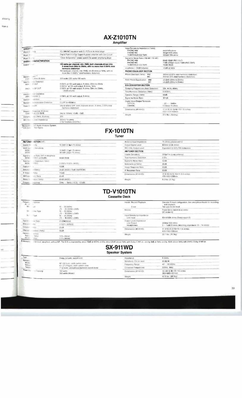
AX-Z1010TN Amplifier
ORctJITF lnp ul Sc nsrtlVlty n mpe rtime ( 1kHZ) PHONO MM 4mVf47 k ohm
~ IIL PHONO Me 3OO~V470 ohms rl IlJII11Pure middotA III Opt Supr-A pVWtll iunpiihf Wllh ~m Crltul fUNERAUXCDt rAP( JOOm VlJ(hlt OIm
(L MM M C OqudllLCr wrltt El FEl s III 11 UI1Stl~~
~ flI)WeI ~ ________ _ bull ~II amp Oynanllcmiddot power syslm rOf power llnlpltYlnQ stilgC SgnaJmiddot10middotNOlse Ratio (66 IHr 78IHF)
PH QNO MM 890018200 IREe OUT) PHONO Me 71 dB (250~V IflPul]f73dB (REC OUT)
100 waitt per chnnel min RlIIS both chnnele driven Irno
~EAAll CHARACTERISTICS
Outpu t lU NERAUXCOITAPf 112d[) 86dB 8 ohma rom 20Hz to 2OkH~ with no more thn 0004 total harmonic dilitortion ~~-3OdB VOlume
-t B (1150Hz
1()5 w1)1s pcl channfl mm RMS mlo aOIml il1 I kH Z uh no PHONO EQUALIZER SECTION ITItI rC than 0 002~ Ictal hilrmomC duUOtlrOn
PhOne OvtllOad ( 1ioH= -M= ----IDOmv (0 02 10WI narfOOnlC tJl SmiddotIOr 101I1----- -- ~--------y~rDy Jla fTTt Me 7mV (0 03 1 01~1 harmtlntc dlSIOt lrOn) ahmlifElottma O Wl [I1J230 W31W 35wii1____2 AIM Pnono EqualQ1ult)R MM to 2dB (20Hz 10 2()ld1l
TOUI Me plusmnO2d8 (2Ot1 l 10 2Jl kH lltit OriIOr hO
our o ()(lol t II t 100 watt oUl pU1 6 ohms 2OHL to 2()HzAU CIA CONVERTER SECTION0OO2-romiddot I1 IO will i OIiJ lpul 8 onms 1kHz Pffi) SPOOT 0009 al 100 wall oulpul 8 0 PlInG 2OHl Io 20kHz SQmptlnQ r rCQue- AO=Cloco CC-CCl2llt - CCCC- --- shyococI7US ---n =-- 7 CC 48 H
2OdO volume TU1UI Hiilmontc DIJ lOrtJon I I kHZ) 0OO3b tto
nUunl Osta rt Oynaml( Rartge l kH z 1 98tJBo004 Jb al 00 wAn cutCRt I 8 ohms ~nal 10-N_0i-lt_R_ _-_-__ toaO
1- ~ 1I1O1JOft oSlrrrolI ctm
OIOllai [nrul Outpu t rormll1r1s TrI)n5iCt 1f1OltIuIiiiUon Onillorll()ll O~LPF 1t- IOOk Hl ) CpnCAL - 23 ~ - 14d8m
~r rI1Ih lHl to 60kHZ ( tHr oolh Chanuctl d lon a ohm 0 0311 fClld COXIAl QgtVp -p 15 Ohms tnrmOt1c lL5tOttlOn)----- 11-31161( I hr 1iI -1 8 1IlCflrtl gt
Frl)Qlll tipOnampe 18 Ohmsl t 3i 173 -459mm J XCOITAPETU 3 t 11)5 116e ~rJ l
Dmiddot 10 1 r1h HIl Qhms) 200
RCeo 1middot tl lm~da(lC( 300mV ~ OMI 2 OV l k ohlllfil (DIGITAL)
bullMaUll t lie AuUtO Analyilli System bull bullCIA Oyn 1 TrJ1 5JgOIiiI
FX-1010TN Tuner
ECTtON (IrtF) Arl lenrlJ Itpu t Im~dllflC1
It 10 JdBI to 9pV 75 ohms) Oulput S~nJll~l
SampnampltlJl ly REG CAL Oltpul LE 1 MOM 14 BdFH ~pV 15 ctmi)
AM TUNER SECTIONSTtn 3B IuS (221IVt75 Mmi) ~sabkj Sar~ ~ltV JmLooP anWnna)
Slgn~ 10 e Rl1 1O HHF-A VfjoqhlOO I MltlN - I1F 0411 85dAI g1 1I] r88d9 TCllitl HumonlC D1stO IQn 0 3
lOtilh DtlltOttlQ t ttoH t EO tl 009 O02-ttb Iw tO(
ScIC-CIIVIIYI Dk_H c -- o~n----------- ______ 3~cGop 12dB IRlagu RespOnre RJi lJll Ll So 250 1middot110pound10_ (YARRO If Response Ral fO 6OltIB Restlt iiiUI1 11003
1- 3 16)3-15 16 X 1I 1 14 tmMS )n Ra tiO 18 a3S lt l OO lt298wm~ I tlllln t IIHzt OOOUIWIOE 82 bs tJ 7kg )~
r twqtefl gt 20HZ - lSIltHl ( f 0 3 - 05dB)
TD-V1010TN Cassette Deck
t fllqltQf middotmiddotponse Dtsc c lo 3-tLOid conhguraltofi line ilInOlphous Md lor lecordtng AI )nd playboD
M 1 Itl 22000Hl TwO~ap jcm head
~ 2() 000lt-lt 3oJB PulBe Sor1O Ilr(Oct-dllffl molOi 10 20000 D( mol0rgtf 2 ~I~l - 8 00Qti7 i3dB I
-ripe Ul 2O000Hl
-=-______--5~ 8000lt-ltl t lO~
~~I wt RaIK) tuBe u fOlJUI JOOmv 6OO nhflIi
~~ Ii0 r ~ O~ iWR~ I S I 0- 1mVNa Ghms IMlIlCtwlo Imoooaflcc 8 - 10 OOfl1Si ~ 17-311 6 lt5middot1H I6X 3 It~ IncheS
ChiUlntl 43Sx l lt10)(3J6mln I ~ lHo 22 7 Ib$ ( 1() 3krll
T shyh~Hll 10li (MoIIII KJ IIh H t) US (MOltll)- Ilri level wo g middotttl tl lithOul NR TM S I N is unpt6vUd by aOOu t lSd8 at 500Hl And by abOtJ I 20dA Ilbo i 1kHZ With Dolby- N~ Of 1lf1lt1 by 5lt18 I lkPZ aM by loee nove 5kHz wtl h ANRSDolby-O NA on
SX-911WDII
Speaker System ~middot 3m a~ ~u-- ~-~o------------------- ------------------------y----us----~p---------------------------------na-- -ohm---------------------------------
Spejlte -~~-~ 91dBrW -----shy1t))4f ~18IIrY~n~lUS_l__ T_ _ 10 5OOOOt1zP
SOOHI _ 4kHl
- 1JQyIIlIS 15lt26 middot3116- 13-718 ches ~no wl11S ( I IJlt) 380 S65x35I m m
W-nt 62a los (2 5111~l ----- ----------------------------------------~=-~~------------~~~~~------------------
33
FX-101 COMPU -co TR ED
IGI lL Y T ESIZER T R Computer control at its most accurate and convenient The primary function of a tuner is to bring in the station you want precisely and accurately whether ii s near or far Using the latest circuit designs and devices weve made our tuner from the SUPER DIGIFINE series the FX-1010TN more sensitive selective and interference resistant than ever- the reason the tuner is able to provide wide dynamic range low noise and low distortion and wide frequency response Its also extremely easy to use thanks to the amazing power of an advanced microprocessor
Reception servo for optimum reception The recept ion servo in the ably clear sound When a signal FX-1010TN ensures the best level is overly strong the RF reception from any station almost gain is reduced to avoid anywhere A bUilt-in microshy saturation distortion when its processor detects the strength of weak sensitivity is increased a tuned station and compares it Moreover the tuner is equipped against the degree of Interference with inputs to connect two antenshyfrom adjacent stations Then nas each may be orienled for the depending on the degree of best reception of stations in interference the microprocessor diametrical opposition to the other selects the optimum operation Conveniently the position of mode for front-end IF and multishy antennas A or S may be stored in plex decoder stages (adjusting memory slation by station wh ich such parameters as RF gain IF allows most precise reception from bandwidth Quieting Slope Control any sta ti on wilhout multipath and monoste reo) Therefore distortion when Interference is exceSSive To add to convenience the a narrow IF bandwidth is aulomat lshy selected paramelers are clearly cally chosen to prevent nOise And indlcaled on a large fluorescen t if theres no interference then display le lling you quickly confirm a wide IF bandwidth is automatishy tuning status cally selected to give you remark-
Flowchart 01 Optimum Reception Servo System
varicaps m selective ar interferencE an elaboratJ capaCItor T noise ratio I
rejection ca
Features for low noise and Low-dlstor low distortion The IF secti JVC uses components and devices mutual interference and nOise middotd featu res cel to ensure lowest possible noise the digital control section whiG with a dlsto and distortion and widest dynamic can be 8 source of noise for b tier pi range from your favorite stations generation is fully shielded 10 distorTi on
contain noise Opticallnk system PLL detect
A PLL dete dlstol lion 81
ratio f r dyr sound
Beatfess P The FX-1011
The Opt icalink system is one mult iplex ci developed by JVC to ensure lilters out b highest pUrity from your lavorile slat ions It uses eleven photocouplers (each consisting of a photoemilier and photosensor) to electrically decouple the analog from fhe digital section As a result interference between the two due to elecfrlc coupt lng is completel y eliminated This puts an end to digital noise and removes any trace of muddiness from the sound you hear
In the FX-1010TN each of the analogtuner digital control and Optlcalink sections is mounted on its own PC board to shut oul
22
Inside view Of the FX-1010TN
I nOise And ln whicll e Ided to
varica ~ makes It as sensitive select e and resistant to interiE lt nce as a front end using an ela orate 5-ganged tuning capac f Therefore the slgnal-toshynoise tio and Interierenceshyrejectrn capability are outstand ing
Low- i tortlon IF section The II ectlon of the FX-1010TN featur 3 ceramic filters coupled with a middot1 tortion reduction circuit lor be -r phase response and low distor i)n
PLL elector A PLL letector combines low distor l n and high signal-to-noise ratio fr ynamic and wide-range sounc
Beatle1s PLL multiplex circuit The F 1010TN uses a new PLL multip bull circuit that electrically lilters II beat nOise-noise
resulting from two or more frequencies interfering with one another In a convenlional CR-Iype MPX circuit using a VCO (VoltageshyControlled Oscillalor) however a device called an anll-birdie filter is used 10 remove beat noise but the coils in the circuit tend to degrade Signal quality In our beatless multiplex CIrcuit moreover a pilot canceller is featured to suppress the leakage of the pilot signal thus obviating the need for a 19kHz filter another component that would harm sound qualily
Active filter To prevent leakage of Ihe 38kHz subcarrier contained in a stereo broadcast an LC filter built from coils and capaCitors IS commonly used but due 10 Ihe magnetic distorlion the core of Ihe cOil causes this system tends to degrade sound quality In the FX-l0l0TN however an acllve filter has replaced the passive LC filter with cOils ehmlnaled il provides better high-frequency response wider separation and higher signal-to-noise ratio
Computer-controlled operating ease With the help of poweriul microcomputers weve also improved tuning ease 01 the FX-l01OTN Iremendously
Station name display You can assign up to six alphanumeric characters to each presel station In the memoryshyJAZZ-8 lor instance
Auto memory All 40 FMIAM stations can be automatically tuned in sequence and committed 10 memory as presets
Random preset memory You can preset as many as 40 FMI AM stations in random order Theres a numeric keypad that allows direct access to any of 40 stations
Preset scan All preset FM IAM slations can be automatically sampled one by one for approximately 5 seconds each
Preset cancel Use this feature to skip undesired preset stations during preset scan
Program memory Up to eight events (broadcasts) can be programmed for sequential recall under the control of an optional timer
AutoQSC The Auto Quieting Slope Control Circuit automatically goes Into action to reduce noise when a station signal is weak
dB-referenced signal strength Indicator Read off the signal strength of a tuned station accurately down to 1dB-a convenience when orienting antennas
Variable stop level Adjust FMI AM muting threshold in 5dB steps over a range during auto tuning The variable stop level feature lets you adjust the threshOld from 20dB to 60dB for FM and from 60dB to 90dB for AM When you use a higher levet youll receive only powerful ctearshysounding stations With weak stations muted out Or when you choose a low level all receivable stations are tuned In
Record calibration slgnaf generator Record calibration signal generator outputs a standard 400Hz signal for recording level adjustment So you can easily set the recording level for different broadcasts or types 01 tape
from a
AX-Z1010TN Amplifier
ORctJITF lnp ul Sc nsrtlVlty n mpe rtime ( 1kHZ) PHONO MM 4mVf47 k ohm
~ IIL PHONO Me 3OO~V470 ohms rl IlJII11Pure middotA III Opt Supr-A pVWtll iunpiihf Wllh ~m Crltul fUNERAUXCDt rAP( JOOm VlJ(hlt OIm
(L MM M C OqudllLCr wrltt El FEl s III 11 UI1Stl~~
~ flI)WeI ~ ________ _ bull ~II amp Oynanllcmiddot power syslm rOf power llnlpltYlnQ stilgC SgnaJmiddot10middotNOlse Ratio (66 IHr 78IHF)
PH QNO MM 890018200 IREe OUT) PHONO Me 71 dB (250~V IflPul]f73dB (REC OUT)
100 waitt per chnnel min RlIIS both chnnele driven Irno
~EAAll CHARACTERISTICS
Outpu t lU NERAUXCOITAPf 112d[) 86dB 8 ohma rom 20Hz to 2OkH~ with no more thn 0004 total harmonic dilitortion ~~-3OdB VOlume
-t B (1150Hz
1()5 w1)1s pcl channfl mm RMS mlo aOIml il1 I kH Z uh no PHONO EQUALIZER SECTION ITItI rC than 0 002~ Ictal hilrmomC duUOtlrOn
PhOne OvtllOad ( 1ioH= -M= ----IDOmv (0 02 10WI narfOOnlC tJl SmiddotIOr 101I1----- -- ~--------y~rDy Jla fTTt Me 7mV (0 03 1 01~1 harmtlntc dlSIOt lrOn) ahmlifElottma O Wl [I1J230 W31W 35wii1____2 AIM Pnono EqualQ1ult)R MM to 2dB (20Hz 10 2()ld1l
TOUI Me plusmnO2d8 (2Ot1 l 10 2Jl kH lltit OriIOr hO
our o ()(lol t II t 100 watt oUl pU1 6 ohms 2OHL to 2()HzAU CIA CONVERTER SECTION0OO2-romiddot I1 IO will i OIiJ lpul 8 onms 1kHz Pffi) SPOOT 0009 al 100 wall oulpul 8 0 PlInG 2OHl Io 20kHz SQmptlnQ r rCQue- AO=Cloco CC-CCl2llt - CCCC- --- shyococI7US ---n =-- 7 CC 48 H
2OdO volume TU1UI Hiilmontc DIJ lOrtJon I I kHZ) 0OO3b tto
nUunl Osta rt Oynaml( Rartge l kH z 1 98tJBo004 Jb al 00 wAn cutCRt I 8 ohms ~nal 10-N_0i-lt_R_ _-_-__ toaO
1- ~ 1I1O1JOft oSlrrrolI ctm
OIOllai [nrul Outpu t rormll1r1s TrI)n5iCt 1f1OltIuIiiiUon Onillorll()ll O~LPF 1t- IOOk Hl ) CpnCAL - 23 ~ - 14d8m
~r rI1Ih lHl to 60kHZ ( tHr oolh Chanuctl d lon a ohm 0 0311 fClld COXIAl QgtVp -p 15 Ohms tnrmOt1c lL5tOttlOn)----- 11-31161( I hr 1iI -1 8 1IlCflrtl gt
Frl)Qlll tipOnampe 18 Ohmsl t 3i 173 -459mm J XCOITAPETU 3 t 11)5 116e ~rJ l
Dmiddot 10 1 r1h HIl Qhms) 200
RCeo 1middot tl lm~da(lC( 300mV ~ OMI 2 OV l k ohlllfil (DIGITAL)
bullMaUll t lie AuUtO Analyilli System bull bullCIA Oyn 1 TrJ1 5JgOIiiI
FX-1010TN Tuner
ECTtON (IrtF) Arl lenrlJ Itpu t Im~dllflC1
It 10 JdBI to 9pV 75 ohms) Oulput S~nJll~l
SampnampltlJl ly REG CAL Oltpul LE 1 MOM 14 BdFH ~pV 15 ctmi)
AM TUNER SECTIONSTtn 3B IuS (221IVt75 Mmi) ~sabkj Sar~ ~ltV JmLooP anWnna)
Slgn~ 10 e Rl1 1O HHF-A VfjoqhlOO I MltlN - I1F 0411 85dAI g1 1I] r88d9 TCllitl HumonlC D1stO IQn 0 3
lOtilh DtlltOttlQ t ttoH t EO tl 009 O02-ttb Iw tO(
ScIC-CIIVIIYI Dk_H c -- o~n----------- ______ 3~cGop 12dB IRlagu RespOnre RJi lJll Ll So 250 1middot110pound10_ (YARRO If Response Ral fO 6OltIB Restlt iiiUI1 11003
1- 3 16)3-15 16 X 1I 1 14 tmMS )n Ra tiO 18 a3S lt l OO lt298wm~ I tlllln t IIHzt OOOUIWIOE 82 bs tJ 7kg )~
r twqtefl gt 20HZ - lSIltHl ( f 0 3 - 05dB)
TD-V1010TN Cassette Deck
t fllqltQf middotmiddotponse Dtsc c lo 3-tLOid conhguraltofi line ilInOlphous Md lor lecordtng AI )nd playboD
M 1 Itl 22000Hl TwO~ap jcm head
~ 2() 000lt-lt 3oJB PulBe Sor1O Ilr(Oct-dllffl molOi 10 20000 D( mol0rgtf 2 ~I~l - 8 00Qti7 i3dB I
-ripe Ul 2O000Hl
-=-______--5~ 8000lt-ltl t lO~
~~I wt RaIK) tuBe u fOlJUI JOOmv 6OO nhflIi
~~ Ii0 r ~ O~ iWR~ I S I 0- 1mVNa Ghms IMlIlCtwlo Imoooaflcc 8 - 10 OOfl1Si ~ 17-311 6 lt5middot1H I6X 3 It~ IncheS
ChiUlntl 43Sx l lt10)(3J6mln I ~ lHo 22 7 Ib$ ( 1() 3krll
T shyh~Hll 10li (MoIIII KJ IIh H t) US (MOltll)- Ilri level wo g middotttl tl lithOul NR TM S I N is unpt6vUd by aOOu t lSd8 at 500Hl And by abOtJ I 20dA Ilbo i 1kHZ With Dolby- N~ Of 1lf1lt1 by 5lt18 I lkPZ aM by loee nove 5kHz wtl h ANRSDolby-O NA on
SX-911WDII
Speaker System ~middot 3m a~ ~u-- ~-~o------------------- ------------------------y----us----~p---------------------------------na-- -ohm---------------------------------
Spejlte -~~-~ 91dBrW -----shy1t))4f ~18IIrY~n~lUS_l__ T_ _ 10 5OOOOt1zP
SOOHI _ 4kHl
- 1JQyIIlIS 15lt26 middot3116- 13-718 ches ~no wl11S ( I IJlt) 380 S65x35I m m
W-nt 62a los (2 5111~l ----- ----------------------------------------~=-~~------------~~~~~------------------
33
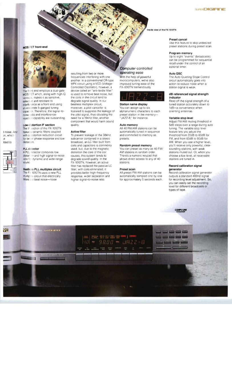