Embed Size (px)
Citation preview
1
Juzisound
Accordion MIDI System
PROGRAM MODES
Juzisound accordion MIDI system have 4 different program modes. Switching between program modes is made
by long pressing (around 6 seconds) of [PRG/HOLD] button. Every program mode is indicated by different
display mode.
2
Program mode 0
In program mode 0, you have direct access by numbers to 1000 program positions. From 000 to 999.
Program selections is made by pressing of 3 digit, or pressing 1 or 2 digit fallowing by pressing of button
[PRG/HOLD].
For example is need to select program 846, need to press buttons [8], [4] and [6]. If need to select program
with number 5, need to press button [5] and [PRG/HOLD].
HOLD Mode
If program is already selected, pressing of button [PRG/HOLD] activate program HOLD mode. Activation of this
mode is indicated by 2 points on number display. In this mode first 2 digits of current program is locked, and
last digit is select direct by pressing of one of number buttons. Selected button is indicated by LED indicator.
Use this mode for very easy and fast change of 10 programs in selected program diapason.
Function on buttons [+] and [-]
In program mode 0, buttons [+] and [-] have 2 different functions, dependent from selected value of parameter
F.28 in EXTENDED SYSTEM PARAMETERS TABLE.
If selected value is 0, these buttons work like direct volume control. With combination of button [PRG/HOLD]
these buttons work like program +/-1.
If function is 1, these buttons work only like program +/-1. If HOLD mode is not activated, buttons [+] and [-]
increased or decreased program number by 1. If hold mode is active, then buttons [+] and [-] increases and
decreases program number by 10.
This program mode 0 is specially created to full control of programs of Juzisound Total SOLO Sampler. When
program is selected, Accordion MIDI system send set of MIDI messages: Control Change 0, Control Change 32
and Program Change. Accepting of combinations of these messages are reassigned in Juzisound Total SOLO
Sampler, but no problem to control any another MIDI device, who accept Bank Select (CC0 and CC32) and
Program Change messages.
Using registers in program mode 0
Register switches work in these mode, for fast selecting predefined program numbers. Assignment of program
mode is made by this procedure:
1. Be sure, you is select another register, different from register who need to program. (This is need, because
midi system need to detect register change when select register who need to program).
2. Manually select program number who need to select, with pressing register button.
3. Press and hold button [PRG/HOLD].
4. Now while holding [PRG/HOLD], press and register button who need to call selected program. After this
release [PRG/HOLD].
With this, procedure is complete, and change is saved in system non-volatile memory. For future, this program
number will be assigned to this register button until new reassignment is executed. If need to reassign another
program to the same button, execute again the same reassign procedure.
WARNING!
Working of register scanning is dependent from 2 things.
1. Need to have sensors with assigned register scanning functions.
2. Global register scanning need to be enabled in Function Menu. (LED on button [4] need to be ON).
3
Program mode 1
In program mode 1, you have fast access to 5 banks and 5 programs in every bank. Total 25 programs.
Bank selections is made by buttons 6, 7, 8, 9 and 0
Program selections is made by buttons 1, 2, 3, 4 and 5.
Current selected bank and program is indicated by button LED.
Function on buttons [+] and [-]
In program mode 1, buttons [+] and [-] have 2 different functions, dependent from selected value of parameter
F.28 in EXTENDED SYSTEM PARAMETERS TABLE.
If selected value is 0, these buttons work like direct volume control. With combination of button [PRG/HOLD]
these buttons work like program +/-1.
If function is 1, these buttons work only like program +/- 1.
Using registers in program mode 1
Register switches work in these mode, for fast selecting predefined bank or program. Assignment registers is
mode by this procedure:
1. Be sure, you is select another register, different from register who need to program. (This is need, because
midi system need to detect register change when select register who need to program).
2. Press and hold pressed buttons for bank (6, 7, 8, 9 or 0) or button for program (1, 2, 3, 4 or 5).
3. While hold pressed button from previous point, press register who need to activate pressed button on
control panel.
With this, procedure is complete, and change is saved in system non-volatile memory. For future, this register
will be activate the selected control panel button, until new reassignment is executed. If need to reassign
another program to the same button, execute again the same reassign procedure.
WARNING!
Working of register scanning is dependent from 2 things.
1. Need to have sensors with assigned register scanning functions.
2. Global register scanning need to be enabled in Function Menu. (LED on button [4] need to be ON).
4
Program mode 2
In program mode 2, you have fast access to 10 banks and 16 programs in every bank. Total 160 programs.
Bank selections is made by number buttons on control panel. Selected bank is indicated by LED.
Program selections is made by register buttons, or by buttons [+] and [-].
Function on buttons [+] and [-]
In program mode 2, buttons [+] and [-] have 2 different functions, dependent from selected value of parameter
F.28 in EXTENDED SYSTEM PARAMETERS TABLE.
If selected value is 0, these buttons work like direct volume control. With combination of button [PRG/HOLD]
these buttons work like program +/-1.
If function is 1, these buttons work like program +/- 1.
Using registers in program mode 2
Register switches work in these mode, for fast selecting predefined program numbers. Assignment registers is
mode by this procedure:
1. Be sure, you is select another register, different from register who need to program. (This is need, because
midi system need to detect register change when select register who need to program).
2. With buttons [+] and [-] manually select desired program number
2. Press and hold button [PRG/HOLD].
3. Now while holding [PRG/HOLD], press and register button who need to call selected program number. After
this release [PRG/HOLD].
With this, procedure is complete, and change is saved in system non-volatile memory. For future, this register
will be activate the selected program number, until new reassignment is executed. If need to reassign another
program to the same button, execute again the same reassign procedure.
WARNING!
Working of register scanning is dependent from 2 things.
1. Need to have sensors with assigned register scanning functions.
2. Global register scanning need to be enabled in Function Menu. (LED on button [4] need to be ON).
5
Program mode 3
In program mode 3, you have fast access to 10 programs and 8 banks. Total 80 programs.
Program selections is made by control panel number buttons or registers, and current selected program is
indicated by button LED.
Bank selections is made only by control panel buttons [+] and [-]. Current selected bank is indicated on LCD
display with chars A, B, C, D, E ,F ,G, H.
Function on buttons [+] and [-]
In program mode 3, buttons [+] and [-] have 2 different functions, dependent from selected value of parameter
F.28 in EXTENDED SYSTEM PARAMETERS TABLE.
If selected value is 0, these buttons work like direct volume control. With combination of button [PRG/HOLD]
these buttons work like bank +/-1.
If function is 1, these buttons work like bank +/- 1.
Using registers in program mode 3
Register switches work in these mode, for fast selecting predefined program numbers. Assignment registers is
mode by this procedure:
1. Be sure, you is select another register, different from register who need to program. (This is need, because
midi system need to detect register change when select register who need to program).
2. With numbers buttons from [0] to [9] manually select desired program number. LED of button will be ON.
2. Press and hold button [PRG/HOLD].
3. Now while holding [PRG/HOLD], press and register button who need to call selected this program number.
After this release [PRG/HOLD].
With this, procedure is complete, and change is saved in system non-volatile memory. For future, this register
will be activate the selected program number, until new reassignment is executed. If need to reassign another
program to the same button, execute again the same reassign procedure.
WARNING!
Working of register scanning is dependent from 2 things.
1. Need to have sensors with assigned register scanning functions.
2. Global register scanning need to be enabled in Function Menu. (LED on button [4] need to be ON).
6
Програм моде
Регистрите се назначават във всички ПРОГРАМ МОДЕ режими по отделно и си се записват в самите
програм модес. Тоест нямат менюта в адвансед функциите.
В програм моде 0 (всички програми по номера) записа става като: 888
1. Трябва да си избрал регистър, различен от този който искаш да запишеш, за да може след това да
натиснеш искания регистър. (Трябва да настъпи промяна за да го отчете платката)
2. Ръчно избираш номера на програмата, който искаш да се яви на регистъра който след малко ще
програмираме.
3. Натискаш и държиш копче [PRG/HOLD].
4. Натискаш искания регистър, докато [PRG/HOLD] е натиснато. Чак тогава пускаш [PRG/HOLD].
С това записа е готов и промяната е отразена и в EEPROM паметта
В програм моде 1 (5 банки с по 5 регистъра всяка) записа става като: 8-8
1. Трябва да си на регистър различен от този който искаш да запишеш.
2. Натискаш и задържаш бутона за банка (номера от 6 до 0) или бутона за регистър (номера от 1 до 5).
3. Докато държиш бутона по предната точка, натискаш и регистъра който искаш да активира този бутон.
С това записа е готов и промяната е отразена и в EEPROM паметта.
В програм моде 2 (10 банки на копчетата на панела с по 16 регистъра всяка) записа става като: 8. 8
1. Трябва да си на регистър различен от този който искаш да запишеш
2. Ръчно избираш с бутони [+] и [-] номера който трябва да активира регистъра който ще програмираме.
2. Натискаш и държиш копче [PRG/HOLD].
3. Докато държиш бутона по предната точка, натискаш и регистъра който ще програмираме.
С това записа е готов и промяната е отразена и в EEPROM паметта
В програм моде 3 (10 регистъра на копчетата на панела и 8 банки с бутони [+] и [-]). 8-8
Банките се изписват с букви A, b, C, D, E, F, G, H:
1. Трябва да си на регистър различен от този който искаш да запишеш
2. Ръчно избираш регистъра с натискане на бутон 0-9 от панела. Избрания номер трябва да светне.
3. Натискаш и задържаш бутона [PRG/HOLD].
4. Докато все още държиш бутона [PRG/HOLD], натискаш и регистъра който ще програмираш.
С това записа е готов и промяната е отразена и в EEPROM паметта.

7
Master Transpose, Terca Control, Scala Control
8
Function Menu Function menu mode is selected by pressing button [FUNC/MENU].
When function mode is active, LED on button [FUNC/MENU] is ON, without blinking.
In function menu, all number buttons on control panel work like switches for different functions. Every button
activate or deactivate one function. If selected function is active, LED on button is ON.
All changes is saved immediate in system non-volatile memory, until next change.
Button Functions:
[6] – Accordion blow (dynamic) On or Off.
If these function is active, scanning of accordion blow is active too. IF function is not active, scanning of
accordion blow is disabled, and accordion work with fixed blow dynamic. Value for fixed dynamic is selected
from extended function menu 6.5.
[7] – Velocity from blow (Note velocity dependent from blow) On or Off.
If these function is active, note velocity produced by MIDI system is dependent from blow pressure. If function
is not active, note velocity is fixed. Fixed value is selected with extended function menu 6.4.
[8] – Pitch Bend scanning On or Off.
If these function is active, accordion MIDI system scanning Pitch Bend analog input. For properly work, need to
have connected potentiometer for Pitch Bend function. If not have connected potentiometer, please stay this
function Off.
[9] – Modulation scanning On or Off.
If these function is active, accordion MIDI system scanning Modulation analog input. For properly work, need
to have connected potentiometer for Modulation function. If not have connected potentiometer, please stay
this function Off.
[0] – Radio (wireless transmitter module) On or Off.
If these function is active, accordion MIDI system activate wireless transmitter module (optional). If you play
with MIDI cable, or not have installed module, please stay this function Off.
[1] – Easy Blow (easy dynamic) On or Off.
If these function is active, accordion MIDI system modify scanning of blow pressure with different user
modified curve. This curve make playing easier, with small blow pressure. With this function, you have fast
switching between natural and easy blow pressure mode.
[2] – Bass (left hand) On or Off.
If these function is active, accordion MIDI system enable working of left hand BASS scanning module.
[3] – Central Register scanning On or Off.
If these function is active, accordion MIDI system enable scanning of central button – long button available on
same models. If you accordion not have this button, not have assigned sensor to this button or not need to use
this function for moment, disable this function.
[4] – Register Button scanning On or Off.
If these function is active, accordion MIDI system activate scanning of register buttons. For properly work of
register scanning, you need to have sensors assigned to register scanning functions, and register buttons need
to be properly programmed. If temporary not need to use register scanning, or not have sensors on register
buttons, switch off this function.
[5] – Volume Potentiometer scanning On or Off.
If these function is active, accordion MIDI system enable scanning of volume potentiometer connected to
control panel. If you not have connected potentiometer, please stay this function Off.
9
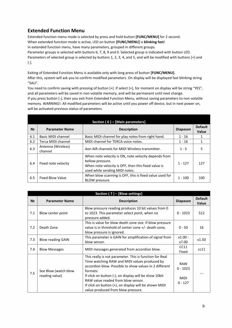
Extended Function Menu Extended function menu mode is selected by press and hold button [FUNC/MENU] for 2 second.
When extended function mode is active, LED on button [FUNC/MENU] is blinking fast!
In extended function menu, have many parameters, grouped in different groups.
Parameter groups is selected with buttons 6, 7, 8, 9 and 0. Selected group is indicated with button LED.
Parameters of selected group is selected by buttons 1, 2, 3, 4, and 5, and will be modified with buttons [+] and
[-].
Exiting of Extended Function Menu is available only with long press of button [FUNC/MENU].
After this, system will ask you to confirm modified parameters. On display will be displayed fast blinking string
“SAU”.
You need to confirm saving with pressing of button [+]. If select [+], for moment on display will be string “YES”,
and all parameters will be saved in non-volatile memory, and will be permanent until next change.
If you press button [-], then you exit from Extended Function Menu, without saving parameters to non-volatile
memory. WARNING!: All modified parameters will be active until you power off device, but in next power on,
will be activated previous status of parameters.
Section ( 6 ) – [Main parameters]
№ Parameter Name Description Diapason Default Value
6.1 Basic MIDI channel Basic MIDI channel for play notes from right hand. 1 - 16 1
6.2 Terca MIDI channel MIDI channel for TERCA voice notes. 1 - 16 1
6.3 Antenna (Wireless) channel
Aon AIR channels for MIDI Wireless transmitter. 1 - 5 5
6.4 Fixed note velocity
When note velocity is ON, note velocity depends from bellow pressure. When note velocity is OFF, then this fixed value is used while sending MIDI notes.
1 - 127 127
6.5 Fixed Blow Value When blow scanning is OFF, this is fixed value used for BLOW pressure.
1 - 100 100
Section ( 7 ) – [Blow settings]
№ Parameter Name Description Diapason Default Value
7.1 Blow center point Blow pressure reading produces 10 bit values from 0 to 1023. This parameter select point, when no pressure added.
0 - 1023 512
7.2 Death Zone This is value for blow death zone size. If blow pressure value is in threshold of center cone +/- death zone, blow pressure is ignored.
0 - 50 16
7.3 Blow reading GAIN This parameter is GAIN for amplification of signal from blow sensor.
x1.00 - x7.00
x1.50
7.4 Blow Messages MIDI messages generated from accordion blow. CC11 Fixed
cc11
7.5 See Blow (watch blow reading value)
This really is not parameter. This is function for Real Time watching RAW and MIDI values produced by accordion blow. Possible to show values in 2 different formats: If click on button (-), on display will be show 10bit RAW value readed from blow sensor. If click on button (+), on display will be shown MIDI value produced from blow pressure.
RAW 0 - 1023
MIDI
0 - 127
---
10
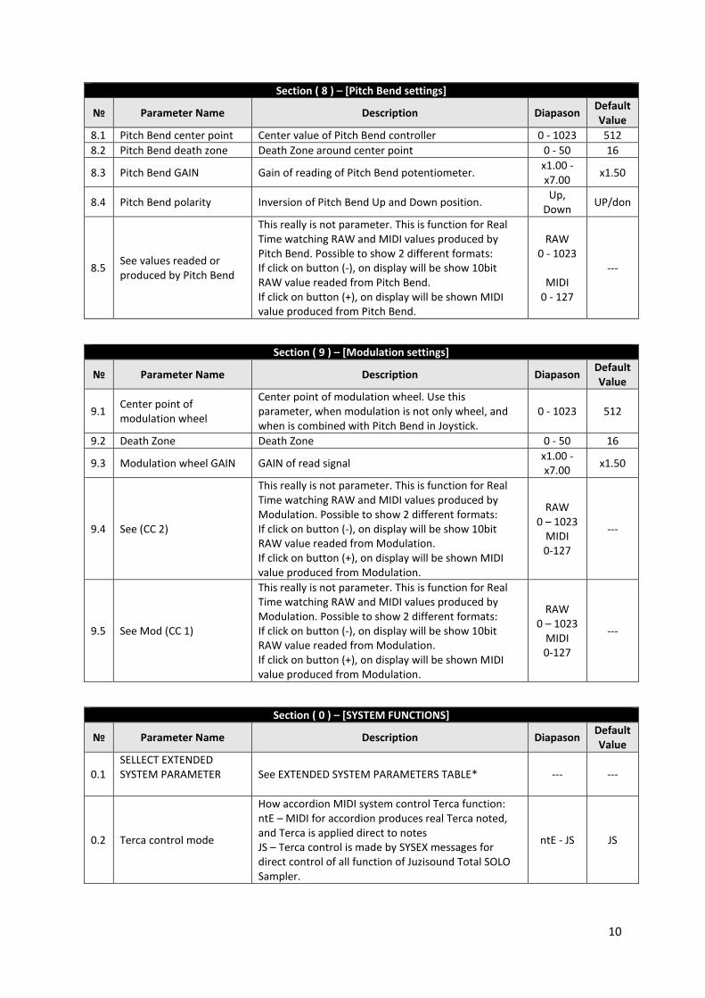
Section ( 8 ) – [Pitch Bend settings]
№ Parameter Name Description Diapason Default Value
8.1 Pitch Bend center point Center value of Pitch Bend controller 0 - 1023 512
8.2 Pitch Bend death zone Death Zone around center point 0 - 50 16
8.3 Pitch Bend GAIN Gain of reading of Pitch Bend potentiometer. x1.00 - x7.00
x1.50
8.4 Pitch Bend polarity Inversion of Pitch Bend Up and Down position. Up,
Down UP/don
8.5 See values readed or produced by Pitch Bend
This really is not parameter. This is function for Real Time watching RAW and MIDI values produced by Pitch Bend. Possible to show 2 different formats: If click on button (-), on display will be show 10bit RAW value readed from Pitch Bend. If click on button (+), on display will be shown MIDI value produced from Pitch Bend.
RAW 0 - 1023
MIDI
0 - 127
---
Section ( 9 ) – [Modulation settings]
№ Parameter Name Description Diapason Default Value
9.1 Center point of modulation wheel
Center point of modulation wheel. Use this parameter, when modulation is not only wheel, and when is combined with Pitch Bend in Joystick.
0 - 1023 512
9.2 Death Zone Death Zone 0 - 50 16
9.3 Modulation wheel GAIN GAIN of read signal x1.00 -x7.00
x1.50
9.4 See (CC 2)
This really is not parameter. This is function for Real Time watching RAW and MIDI values produced by Modulation. Possible to show 2 different formats: If click on button (-), on display will be show 10bit RAW value readed from Modulation. If click on button (+), on display will be shown MIDI value produced from Modulation.
RAW 0 – 1023
MIDI 0-127
---
9.5 See Mod (CC 1)
This really is not parameter. This is function for Real Time watching RAW and MIDI values produced by Modulation. Possible to show 2 different formats: If click on button (-), on display will be show 10bit RAW value readed from Modulation. If click on button (+), on display will be shown MIDI value produced from Modulation.
RAW 0 – 1023
MIDI 0-127
---
Section ( 0 ) – [SYSTEM FUNCTIONS]
№ Parameter Name Description Diapason Default Value
0.1 SELLECT EXTENDED SYSTEM PARAMETER
See EXTENDED SYSTEM PARAMETERS TABLE* --- ---
0.2 Terca control mode
How accordion MIDI system control Terca function: ntE – MIDI for accordion produces real Terca noted, and Terca is applied direct to notes JS – Terca control is made by SYSEX messages for direct control of all function of Juzisound Total SOLO Sampler.
ntE - JS JS
11
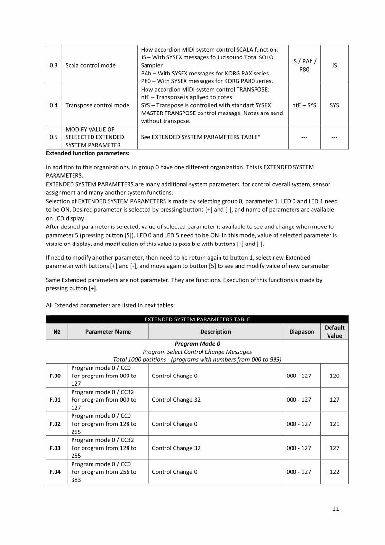
0.3 Scala control mode
How accordion MIDI system control SCALA function: JS – With SYSEX messages fo Juzisound Total SOLO Sampler PAh – With SYSEX messages for KORG PAX series. P80 – With SYSEX messages for KORG PA80 series.
JS / PAh / P80
JS
0.4 Transpose control mode
How accordion MIDI system control TRANSPOSE: ntE – Transpose is apllyed to notes SYS – Transpose is controlled with standart SYSEX MASTER TRANSPOSE control message. Notes are send without transpose.
ntE – SYS SYS
0.5 MODIFY VALUE OF SELEECTED EXTENDED SYSTEM PARAMETER
See EXTENDED SYSTEM PARAMETERS TABLE* --- ---
Extended function parameters:
In addition to this organizations, in group 0 have one different organization. This is EXTENDED SYSTEM
PARAMETERS.
EXTENDED SYSTEM PARAMETERS are many additional system parameters, for control overall system, sensor
assignment and many another system functions.
Selection of EXTENDED SYSTEM PARAMETERS is made by selecting group 0, parameter 1. LED 0 and LED 1 need
to be ON. Desired parameter is selected by pressing buttons [+] and [-], and name of parameters are available
on LCD display.
After desired parameter is selected, value of selected parameter is available to see and change when move to
parameter 5 (pressing button [5]). LED 0 and LED 5 need to be ON. In this mode, value of selected parameter is
visible on display, and modification of this value is possible with buttons [+] and [-].
If need to modify another parameter, then need to be return again to button 1, select new Extended
parameter with buttons [+] and [-], and move again to button [5] to see and modify value of new parameter.
Same Extended parameters are not parameter. They are functions. Execution of this functions is made by
pressing button [+].
All Extended parameters are listed in next tables:
EXTENDED SYSTEM PARAMETERS TABLE
№ Parameter Name Description Diapason Default Value
Program Mode 0 Program Select Control Change Messages
Total 1000 positions - (programs with numbers from 000 to 999)
F.00 Program mode 0 / CC0 For program from 000 to 127
Control Change 0 000 - 127 120
F.01 Program mode 0 / CC32 For program from 000 to 127
Control Change 32 000 - 127 127
F.02 Program mode 0 / CC0 For program from 128 to 255
Control Change 0 000 - 127 121
F.03 Program mode 0 / CC32 For program from 128 to 255
Control Change 32 000 - 127 127
F.04 Program mode 0 / CC0 For program from 256 to 383
Control Change 0 000 - 127 122
12
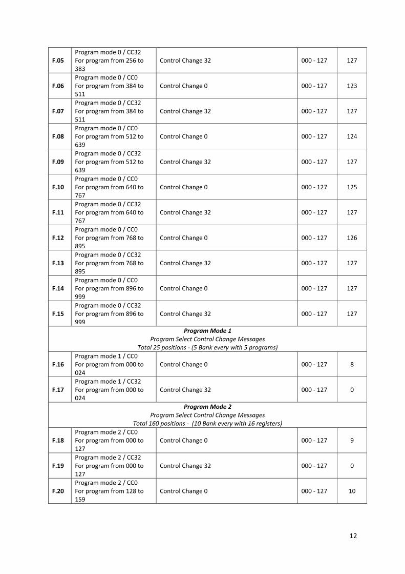
F.05 Program mode 0 / CC32 For program from 256 to 383
Control Change 32 000 - 127 127
F.06 Program mode 0 / CC0 For program from 384 to 511
Control Change 0 000 - 127 123
F.07 Program mode 0 / CC32 For program from 384 to 511
Control Change 32 000 - 127 127
F.08 Program mode 0 / CC0 For program from 512 to 639
Control Change 0 000 - 127 124
F.09 Program mode 0 / CC32 For program from 512 to 639
Control Change 32 000 - 127 127
F.10 Program mode 0 / CC0 For program from 640 to 767
Control Change 0 000 - 127 125
F.11 Program mode 0 / CC32 For program from 640 to 767
Control Change 32 000 - 127 127
F.12 Program mode 0 / CC0 For program from 768 to 895
Control Change 0 000 - 127 126
F.13 Program mode 0 / CC32 For program from 768 to 895
Control Change 32 000 - 127 127
F.14 Program mode 0 / CC0 For program from 896 to 999
Control Change 0 000 - 127 127
F.15 Program mode 0 / CC32 For program from 896 to 999
Control Change 32 000 - 127 127
Program Mode 1 Program Select Control Change Messages
Total 25 positions - (5 Bank every with 5 programs)
F.16 Program mode 1 / CC0 For program from 000 to 024
Control Change 0 000 - 127 8
F.17 Program mode 1 / CC32 For program from 000 to 024
Control Change 32 000 - 127 0
Program Mode 2 Program Select Control Change Messages
Total 160 positions - (10 Bank every with 16 registers)
F.18 Program mode 2 / CC0 For program from 000 to 127
Control Change 0 000 - 127 9
F.19 Program mode 2 / CC32 For program from 000 to 127
Control Change 32 000 - 127 0
F.20 Program mode 2 / CC0 For program from 128 to 159
Control Change 0 000 - 127 10
13
F.21 Program mode 2 / CC32 For program from 128 to 159
Control Change 32 000 - 127 0
Program Mode 3 Program Select Control Change Messages
Total 80 positions - (8 Bank every with 10 programs)
F.22 Program mode 3 / CC0 For program from 000 to 079
Control Change 0 000 - 127 11
F.23 Program mode 3 / CC32 For program from 000 to 079
Control Change 32 000 - 127 0
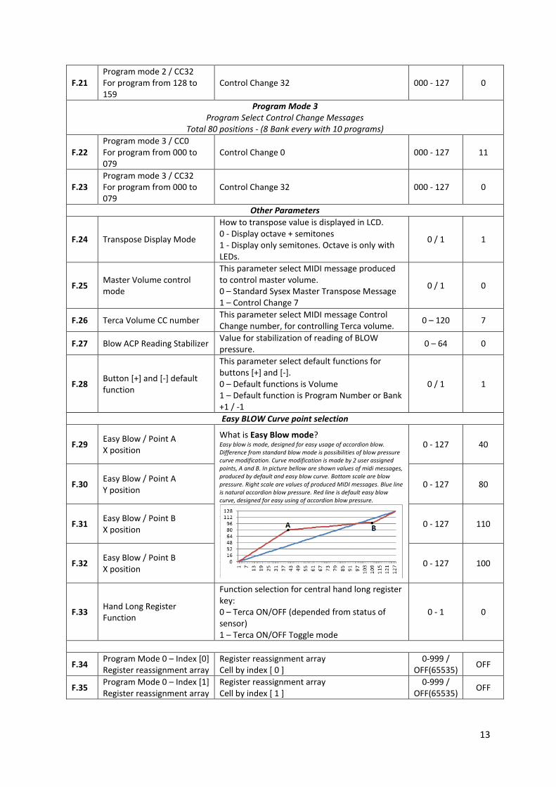
Other Parameters
F.24 Transpose Display Mode
How to transpose value is displayed in LCD. 0 - Display octave + semitones 1 - Display only semitones. Octave is only with LEDs.
0 / 1 1
F.25 Master Volume control mode
This parameter select MIDI message produced to control master volume. 0 – Standard Sysex Master Transpose Message 1 – Control Change 7
0 / 1 0
F.26 Terca Volume CC number This parameter select MIDI message Control Change number, for controlling Terca volume.
0 – 120 7
F.27 Blow ACP Reading Stabilizer Value for stabilization of reading of BLOW pressure.
0 – 64 0
F.28 Button [+] and [-] default function
This parameter select default functions for buttons [+] and [-]. 0 – Default functions is Volume 1 – Default function is Program Number or Bank +1 / -1
0 / 1 1
Easy BLOW Curve point selection
F.29 Easy Blow / Point A X position
What is Easy Blow mode? Easy blow is mode, designed for easy usage of accordion blow. Difference from standard blow mode is possibilities of blow pressure curve modification. Curve modification is made by 2 user assigned points, A and B. In picture bellow are shown values of midi messages, produced by default and easy blow curve. Bottom scale are blow pressure. Right scale are values of produced MIDI messages. Blue line is natural accordion blow pressure. Red line is default easy blow curve, designed for easy using of accordion blow pressure.
0 - 127 40
F.30 Easy Blow / Point A Y position
0 - 127 80
F.31 Easy Blow / Point B X position
0 - 127 110
F.32 Easy Blow / Point B X position
0 - 127 100
F.33 Hand Long Register Function
Function selection for central hand long register key: 0 – Terca ON/OFF (depended from status of sensor) 1 – Terca ON/OFF Toggle mode
0 - 1 0
F.34 Program Mode 0 – Index [0] Register reassignment array
Register reassignment array Cell by index [ 0 ]
0-999 / OFF(65535)
OFF
F.35 Program Mode 0 – Index [1] Register reassignment array
Register reassignment array Cell by index [ 1 ]
0-999 / OFF(65535)
OFF
14
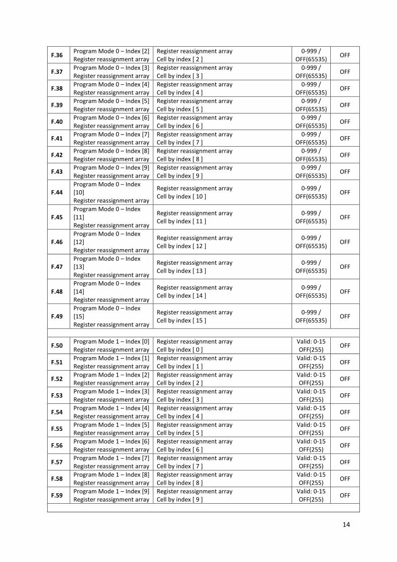
F.36 Program Mode 0 – Index [2] Register reassignment array
Register reassignment array Cell by index [ 2 ]
0-999 / OFF(65535)
OFF
F.37 Program Mode 0 – Index [3] Register reassignment array
Register reassignment array Cell by index [ 3 ]
0-999 / OFF(65535)
OFF
F.38 Program Mode 0 – Index [4] Register reassignment array
Register reassignment array Cell by index [ 4 ]
0-999 / OFF(65535)
OFF
F.39 Program Mode 0 – Index [5] Register reassignment array
Register reassignment array Cell by index [ 5 ]
0-999 / OFF(65535)
OFF
F.40 Program Mode 0 – Index [6] Register reassignment array
Register reassignment array Cell by index [ 6 ]
0-999 / OFF(65535)
OFF
F.41 Program Mode 0 – Index [7] Register reassignment array
Register reassignment array Cell by index [ 7 ]
0-999 / OFF(65535)
OFF
F.42 Program Mode 0 – Index [8] Register reassignment array
Register reassignment array Cell by index [ 8 ]
0-999 / OFF(65535)
OFF
F.43 Program Mode 0 – Index [9] Register reassignment array
Register reassignment array Cell by index [ 9 ]
0-999 / OFF(65535)
OFF
F.44 Program Mode 0 – Index [10] Register reassignment array
Register reassignment array Cell by index [ 10 ]
0-999 / OFF(65535)
OFF
F.45 Program Mode 0 – Index [11] Register reassignment array
Register reassignment array Cell by index [ 11 ]
0-999 / OFF(65535)
OFF
F.46 Program Mode 0 – Index [12] Register reassignment array
Register reassignment array Cell by index [ 12 ]
0-999 / OFF(65535)
OFF
F.47 Program Mode 0 – Index [13] Register reassignment array
Register reassignment array Cell by index [ 13 ]
0-999 / OFF(65535)
OFF
F.48 Program Mode 0 – Index [14] Register reassignment array
Register reassignment array Cell by index [ 14 ]
0-999 / OFF(65535)
OFF
F.49 Program Mode 0 – Index [15] Register reassignment array
Register reassignment array Cell by index [ 15 ]
0-999 / OFF(65535)
OFF
F.50 Program Mode 1 – Index [0] Register reassignment array
Register reassignment array Cell by index [ 0 ]
Valid: 0-15 OFF(255)
OFF
F.51 Program Mode 1 – Index [1] Register reassignment array
Register reassignment array Cell by index [ 1 ]
Valid: 0-15 OFF(255)
OFF
F.52 Program Mode 1 – Index [2] Register reassignment array
Register reassignment array Cell by index [ 2 ]
Valid: 0-15 OFF(255)
OFF
F.53 Program Mode 1 – Index [3] Register reassignment array
Register reassignment array Cell by index [ 3 ]
Valid: 0-15 OFF(255)
OFF
F.54 Program Mode 1 – Index [4] Register reassignment array
Register reassignment array Cell by index [ 4 ]
Valid: 0-15 OFF(255)
OFF
F.55 Program Mode 1 – Index [5] Register reassignment array
Register reassignment array Cell by index [ 5 ]
Valid: 0-15 OFF(255)
OFF
F.56 Program Mode 1 – Index [6] Register reassignment array
Register reassignment array Cell by index [ 6 ]
Valid: 0-15 OFF(255)
OFF
F.57 Program Mode 1 – Index [7] Register reassignment array
Register reassignment array Cell by index [ 7 ]
Valid: 0-15 OFF(255)
OFF
F.58 Program Mode 1 – Index [8] Register reassignment array
Register reassignment array Cell by index [ 8 ]
Valid: 0-15 OFF(255)
OFF
F.59 Program Mode 1 – Index [9] Register reassignment array
Register reassignment array Cell by index [ 9 ]
Valid: 0-15 OFF(255)
OFF
15
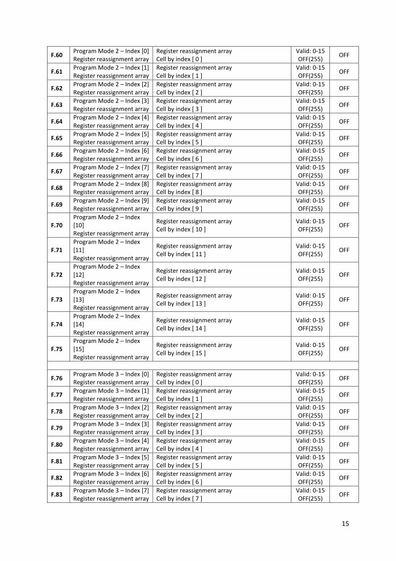
F.60 Program Mode 2 – Index [0] Register reassignment array
Register reassignment array Cell by index [ 0 ]
Valid: 0-15 OFF(255)
OFF
F.61 Program Mode 2 – Index [1] Register reassignment array
Register reassignment array Cell by index [ 1 ]
Valid: 0-15 OFF(255)
OFF
F.62 Program Mode 2 – Index [2] Register reassignment array
Register reassignment array Cell by index [ 2 ]
Valid: 0-15 OFF(255)
OFF
F.63 Program Mode 2 – Index [3] Register reassignment array
Register reassignment array Cell by index [ 3 ]
Valid: 0-15 OFF(255)
OFF
F.64 Program Mode 2 – Index [4] Register reassignment array
Register reassignment array Cell by index [ 4 ]
Valid: 0-15 OFF(255)
OFF
F.65 Program Mode 2 – Index [5] Register reassignment array
Register reassignment array Cell by index [ 5 ]
Valid: 0-15 OFF(255)
OFF
F.66 Program Mode 2 – Index [6] Register reassignment array
Register reassignment array Cell by index [ 6 ]
Valid: 0-15 OFF(255)
OFF
F.67 Program Mode 2 – Index [7] Register reassignment array
Register reassignment array Cell by index [ 7 ]
Valid: 0-15 OFF(255)
OFF
F.68 Program Mode 2 – Index [8] Register reassignment array
Register reassignment array Cell by index [ 8 ]
Valid: 0-15 OFF(255)
OFF
F.69 Program Mode 2 – Index [9] Register reassignment array
Register reassignment array Cell by index [ 9 ]
Valid: 0-15 OFF(255)
OFF
F.70 Program Mode 2 – Index [10] Register reassignment array
Register reassignment array Cell by index [ 10 ]
Valid: 0-15 OFF(255)
OFF
F.71 Program Mode 2 – Index [11] Register reassignment array
Register reassignment array Cell by index [ 11 ]
Valid: 0-15 OFF(255)
OFF
F.72 Program Mode 2 – Index [12] Register reassignment array
Register reassignment array Cell by index [ 12 ]
Valid: 0-15 OFF(255)
OFF
F.73 Program Mode 2 – Index [13] Register reassignment array
Register reassignment array Cell by index [ 13 ]
Valid: 0-15 OFF(255)
OFF
F.74 Program Mode 2 – Index [14] Register reassignment array
Register reassignment array Cell by index [ 14 ]
Valid: 0-15 OFF(255)
OFF
F.75 Program Mode 2 – Index [15] Register reassignment array
Register reassignment array Cell by index [ 15 ]
Valid: 0-15 OFF(255)
OFF
F.76 Program Mode 3 – Index [0] Register reassignment array
Register reassignment array Cell by index [ 0 ]
Valid: 0-15 OFF(255)
OFF
F.77 Program Mode 3 – Index [1] Register reassignment array
Register reassignment array Cell by index [ 1 ]
Valid: 0-15 OFF(255)
OFF
F.78 Program Mode 3 – Index [2] Register reassignment array
Register reassignment array Cell by index [ 2 ]
Valid: 0-15 OFF(255)
OFF
F.79 Program Mode 3 – Index [3] Register reassignment array
Register reassignment array Cell by index [ 3 ]
Valid: 0-15 OFF(255)
OFF
F.80 Program Mode 3 – Index [4] Register reassignment array
Register reassignment array Cell by index [ 4 ]
Valid: 0-15 OFF(255)
OFF
F.81 Program Mode 3 – Index [5] Register reassignment array
Register reassignment array Cell by index [ 5 ]
Valid: 0-15 OFF(255)
OFF
F.82 Program Mode 3 – Index [6] Register reassignment array
Register reassignment array Cell by index [ 6 ]
Valid: 0-15 OFF(255)
OFF
F.83 Program Mode 3 – Index [7] Register reassignment array
Register reassignment array Cell by index [ 7 ]
Valid: 0-15 OFF(255)
OFF
16
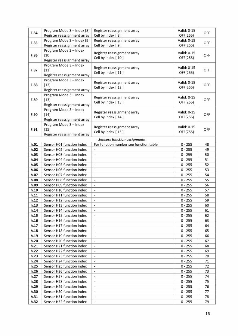
F.84 Program Mode 3 – Index [8] Register reassignment array
Register reassignment array Cell by index [ 8 ]
Valid: 0-15 OFF(255)
OFF
F.85 Program Mode 3 – Index [9] Register reassignment array
Register reassignment array Cell by index [ 9 ]
Valid: 0-15 OFF(255)
OFF
F.86 Program Mode 3 – Index [10] Register reassignment array
Register reassignment array Cell by index [ 10 ]
Valid: 0-15 OFF(255)
OFF
F.87 Program Mode 3 – Index [11] Register reassignment array
Register reassignment array Cell by index [ 11 ]
Valid: 0-15 OFF(255)
OFF
F.88 Program Mode 3 – Index [12] Register reassignment array
Register reassignment array Cell by index [ 12 ]
Valid: 0-15 OFF(255)
OFF
F.89 Program Mode 3 – Index [13] Register reassignment array
Register reassignment array Cell by index [ 13 ]
Valid: 0-15 OFF(255)
OFF
F.90 Program Mode 3 – Index [14] Register reassignment array
Register reassignment array Cell by index [ 14 ]
Valid: 0-15 OFF(255)
OFF
F.91 Program Mode 3 – Index [15] Register reassignment array
Register reassignment array Cell by index [ 15 ]
Valid: 0-15 OFF(255)
OFF
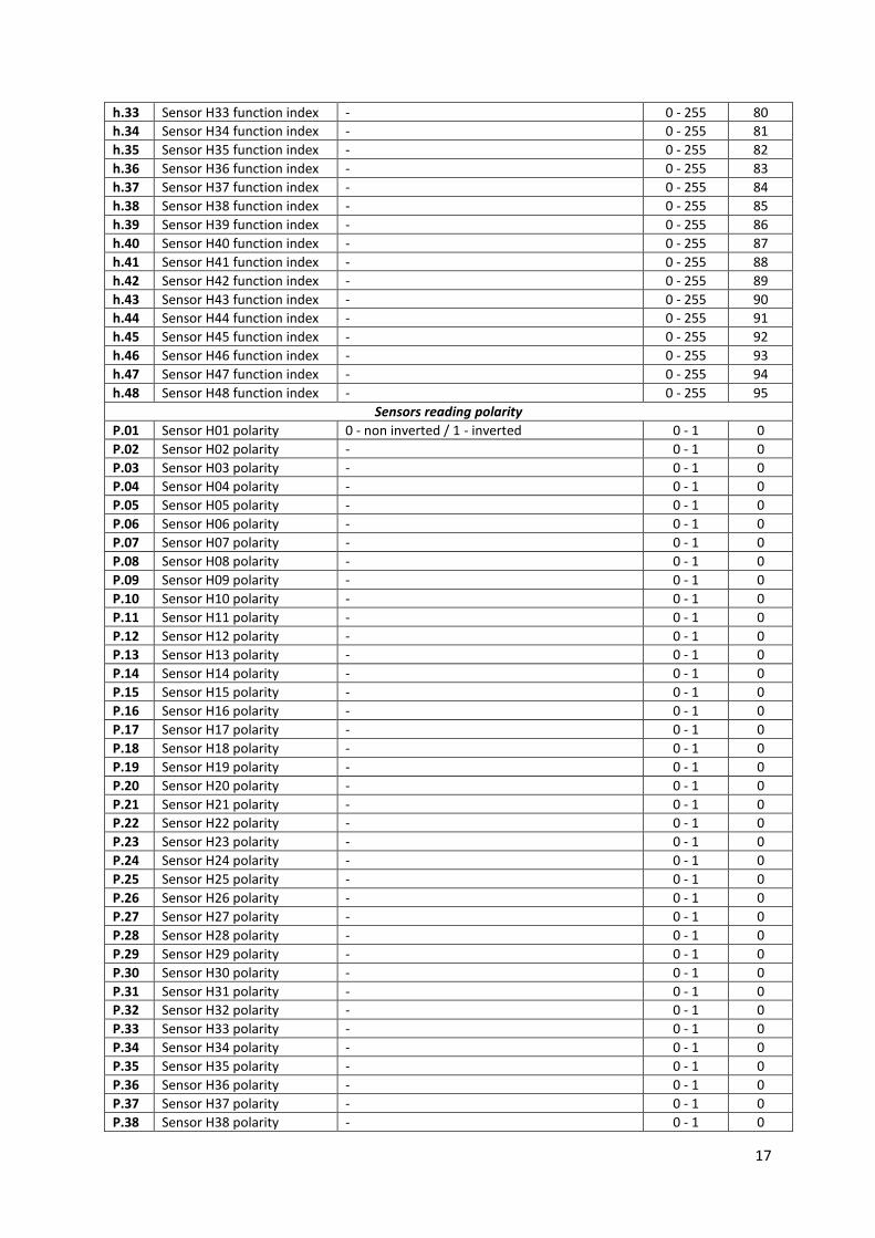
Sensors function assignment
h.01 Sensor H01 function index For function number see function table 0 - 255 48
h.02 Sensor H02 function index - 0 - 255 49
h.03 Sensor H03 function index - 0 - 255 50
h.04 Sensor H04 function index - 0 - 255 51
h.05 Sensor H05 function index - 0 - 255 52
h.06 Sensor H06 function index - 0 - 255 53
h.07 Sensor H07 function index - 0 - 255 54
h.08 Sensor H08 function index - 0 - 255 55
h.09 Sensor H09 function index - 0 - 255 56
h.10 Sensor H10 function index - 0 - 255 57
h.11 Sensor H11 function index - 0 - 255 58
h.12 Sensor H12 function index - 0 - 255 59
h.13 Sensor H13 function index - 0 - 255 60
h.14 Sensor H14 function index - 0 - 255 61
h.15 Sensor H15 function index - 0 - 255 62
h.16 Sensor H16 function index - 0 - 255 63
h.17 Sensor H17 function index - 0 - 255 64
h.18 Sensor H18 function index - 0 - 255 65
h.19 Sensor H19 function index - 0 - 255 66
h.20 Sensor H20 function index - 0 - 255 67
h.21 Sensor H21 function index - 0 - 255 68
h.22 Sensor H22 function index - 0 - 255 69
h.23 Sensor H23 function index - 0 - 255 70
h.24 Sensor H24 function index - 0 - 255 71
h.25 Sensor H25 function index - 0 - 255 72
h.26 Sensor H26 function index - 0 - 255 73
h.27 Sensor H27 function index - 0 - 255 74
h.28 Sensor H28 function index - 0 - 255 75
h.29 Sensor H29 function index - 0 - 255 76
h.30 Sensor H30 function index - 0 - 255 77
h.31 Sensor H31 function index - 0 - 255 78
h.32 Sensor H32 function index - 0 - 255 79
17
h.33 Sensor H33 function index - 0 - 255 80
h.34 Sensor H34 function index - 0 - 255 81
h.35 Sensor H35 function index - 0 - 255 82
h.36 Sensor H36 function index - 0 - 255 83
h.37 Sensor H37 function index - 0 - 255 84
h.38 Sensor H38 function index - 0 - 255 85
h.39 Sensor H39 function index - 0 - 255 86
h.40 Sensor H40 function index - 0 - 255 87
h.41 Sensor H41 function index - 0 - 255 88
h.42 Sensor H42 function index - 0 - 255 89
h.43 Sensor H43 function index - 0 - 255 90
h.44 Sensor H44 function index - 0 - 255 91
h.45 Sensor H45 function index - 0 - 255 92
h.46 Sensor H46 function index - 0 - 255 93
h.47 Sensor H47 function index - 0 - 255 94
h.48 Sensor H48 function index - 0 - 255 95
Sensors reading polarity
P.01 Sensor H01 polarity 0 - non inverted / 1 - inverted 0 - 1 0
P.02 Sensor H02 polarity - 0 - 1 0
P.03 Sensor H03 polarity - 0 - 1 0
P.04 Sensor H04 polarity - 0 - 1 0
P.05 Sensor H05 polarity - 0 - 1 0
P.06 Sensor H06 polarity - 0 - 1 0
P.07 Sensor H07 polarity - 0 - 1 0
P.08 Sensor H08 polarity - 0 - 1 0
P.09 Sensor H09 polarity - 0 - 1 0
P.10 Sensor H10 polarity - 0 - 1 0
P.11 Sensor H11 polarity - 0 - 1 0
P.12 Sensor H12 polarity - 0 - 1 0
P.13 Sensor H13 polarity - 0 - 1 0
P.14 Sensor H14 polarity - 0 - 1 0
P.15 Sensor H15 polarity - 0 - 1 0
P.16 Sensor H16 polarity - 0 - 1 0
P.17 Sensor H17 polarity - 0 - 1 0
P.18 Sensor H18 polarity - 0 - 1 0
P.19 Sensor H19 polarity - 0 - 1 0
P.20 Sensor H20 polarity - 0 - 1 0
P.21 Sensor H21 polarity - 0 - 1 0
P.22 Sensor H22 polarity - 0 - 1 0
P.23 Sensor H23 polarity - 0 - 1 0
P.24 Sensor H24 polarity - 0 - 1 0
P.25 Sensor H25 polarity - 0 - 1 0
P.26 Sensor H26 polarity - 0 - 1 0
P.27 Sensor H27 polarity - 0 - 1 0
P.28 Sensor H28 polarity - 0 - 1 0
P.29 Sensor H29 polarity - 0 - 1 0
P.30 Sensor H30 polarity - 0 - 1 0
P.31 Sensor H31 polarity - 0 - 1 0
P.32 Sensor H32 polarity - 0 - 1 0
P.33 Sensor H33 polarity - 0 - 1 0
P.34 Sensor H34 polarity - 0 - 1 0
P.35 Sensor H35 polarity - 0 - 1 0
P.36 Sensor H36 polarity - 0 - 1 0
P.37 Sensor H37 polarity - 0 - 1 0
P.38 Sensor H38 polarity - 0 - 1 0
18
P.39 Sensor H39 polarity - 0 - 1 0
P.40 Sensor H40 polarity - 0 - 1 0
P.41 Sensor H41 polarity - 0 - 1 0
P.42 Sensor H42 polarity - 0 - 1 0
P.43 Sensor H43 polarity - 0 - 1 0
P.44 Sensor H44 polarity - 0 - 1 0
P.45 Sensor H45 polarity - 0 - 1 0
P.46 Sensor H46 polarity - 0 - 1 0
P.47 Sensor H47 polarity - 0 - 1 0
P.48 Sensor H48 polarity - 0 - 1 0
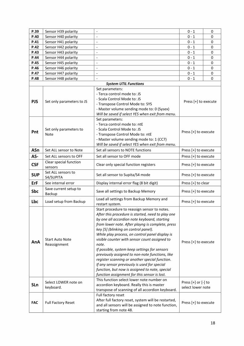
System UTIL Functions
PJS Set only parameters to JS
Set parameters: - Terca control mode to: JS - Scala Control Mode to: JS - Transpose Control Mode to: SYS - Master volume sending mode to: 0 (Sysex) Will be saved if select YES when exit from menu.
Press [+] to execute
Pnt Set only parameters to Note
Set parameters: - Terca control mode to: ntE - Scala Control Mode to: JS - Transpose Control Mode to: ntE - Master volume sending mode to: 1 (CC7) Will be saved if select YES when exit from menu.
Press [+] to execute
ASn Set ALL sensor to Note Set all sensors to NOTE functions Press [+] to execute
AS- Set ALL sensors to OFF Set all sensor to OFF mode Press [+] to execute
CSF Clear special function sensors
Clear only special function registers Press [+] to execute
SUP Set ALL sensors to S4/SUPITA
Set all sensor to Supita/S4 mode Press [+] to execute
ErF See internal error Display internal error flag (8 bit digit) Press [+] to clear
Sbc Save current setup to Backup
Save all settings to Backup Memory Press [+] to execute
Lbc Load setup from Backup Load all settings from Backup Memory and restart system.
Press [+] to execute
AnA Start Auto Note Reassignment
Start procedure to reassign sensor to notes. After this procedure is started, need to play one by one all accordion note keyboard, starting from lower note. After playng is complete, press key [5] (blinking on control panel). While play process, on control panel display is visible counter with sensor count assigned to note. If possible, system keep settings for sensors previously assigned to non-note functions, like register scanning or another special function. If any sensor previously is used for special function, but now is assigned to note, special function assignment for this sensor is lost.
Press [+] to execute
SLn Select LOWER note on keyboard.
This function select lower note number on accordion keyboard. Really this is master transpose of scanning of all accordion keyboard.
Press [+] or [-] to select lower note
FAC Full Factory Reset
Full factory reset After full factory reset, system will be restarted, and all sensors will be assigned to note function, starting from note 48.
Press [+] to execute
19
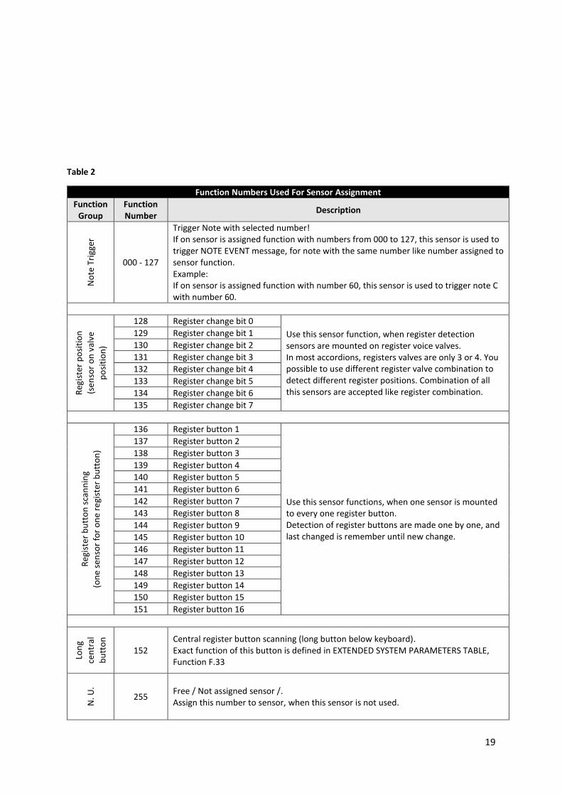
Table 2
Function Numbers Used For Sensor Assignment
Function Group
Function Number
Description
No
te T
rigg
er
000 - 127
Trigger Note with selected number! If on sensor is assigned function with numbers from 000 to 127, this sensor is used to trigger NOTE EVENT message, for note with the same number like number assigned to sensor function. Example: If on sensor is assigned function with number 60, this sensor is used to trigger note C with number 60.
Reg
iste
r p
osi
tio
n
(sen
sor
on
val
ve
po
siti
on
)
128 Register change bit 0
Use this sensor function, when register detection sensors are mounted on register voice valves. In most accordions, registers valves are only 3 or 4. You possible to use different register valve combination to detect different register positions. Combination of all this sensors are accepted like register combination.
129 Register change bit 1
130 Register change bit 2
131 Register change bit 3
132 Register change bit 4
133 Register change bit 5
134 Register change bit 6
135 Register change bit 7
Reg
iste
r b
utt
on
sca
nn
ing
(on
e se
nso
r fo
r o
ne
regi
ster
bu
tto
n)
136 Register button 1
Use this sensor functions, when one sensor is mounted to every one register button. Detection of register buttons are made one by one, and last changed is remember until new change.
137 Register button 2
138 Register button 3
139 Register button 4
140 Register button 5
141 Register button 6
142 Register button 7
143 Register button 8
144 Register button 9
145 Register button 10
146 Register button 11
147 Register button 12
148 Register button 13
149 Register button 14
150 Register button 15
151 Register button 16
Lon
g
cen
tral
bu
tto
n
152 Central register button scanning (long button below keyboard). Exact function of this button is defined in EXTENDED SYSTEM PARAMETERS TABLE, Function F.33
N. U
.
255 Free / Not assigned sensor /. Assign this number to sensor, when this sensor is not used.
20
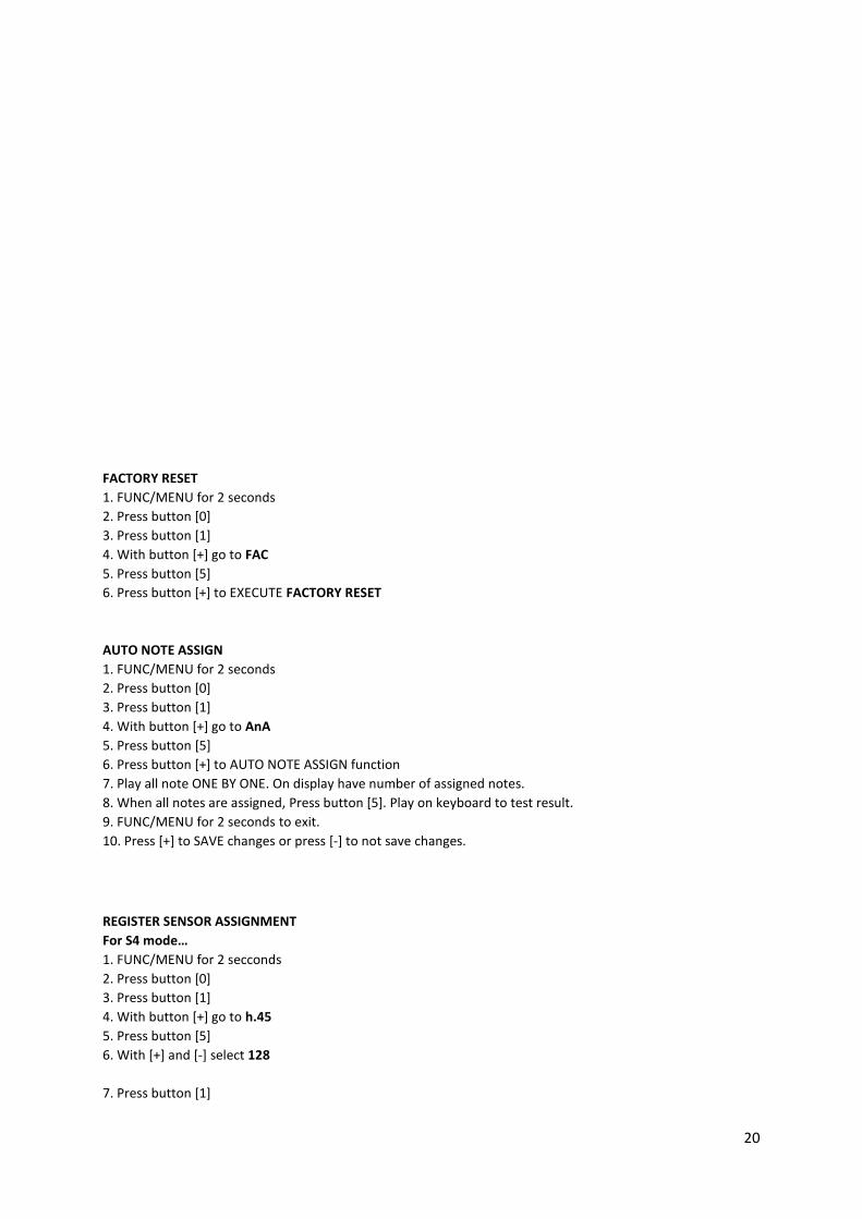
FACTORY RESET
1. FUNC/MENU for 2 seconds
2. Press button [0]
3. Press button [1]
4. With button [+] go to FAC
5. Press button [5]
6. Press button [+] to EXECUTE FACTORY RESET
AUTO NOTE ASSIGN
1. FUNC/MENU for 2 seconds
2. Press button [0]
3. Press button [1]
4. With button [+] go to AnA
5. Press button [5]
6. Press button [+] to AUTO NOTE ASSIGN function
7. Play all note ONE BY ONE. On display have number of assigned notes.
8. When all notes are assigned, Press button [5]. Play on keyboard to test result.
9. FUNC/MENU for 2 seconds to exit.
10. Press [+] to SAVE changes or press [-] to not save changes.
REGISTER SENSOR ASSIGNMENT
For S4 mode…
1. FUNC/MENU for 2 secconds
2. Press button [0]
3. Press button [1]
4. With button [+] go to h.45
5. Press button [5]
6. With [+] and [-] select 128
7. Press button [1]
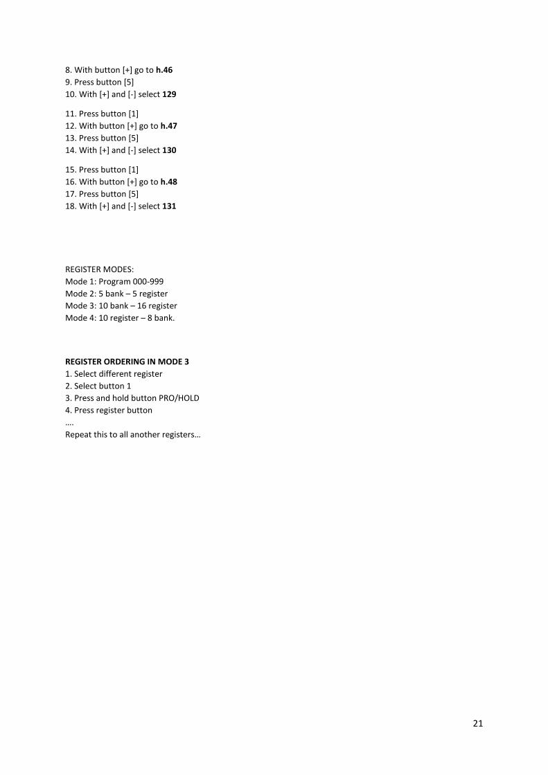
21
8. With button [+] go to h.46
9. Press button [5]
10. With [+] and [-] select 129
11. Press button [1]
12. With button [+] go to h.47
13. Press button [5]
14. With [+] and [-] select 130
15. Press button [1]
16. With button [+] go to h.48
17. Press button [5]
18. With [+] and [-] select 131
REGISTER MODES:
Mode 1: Program 000-999
Mode 2: 5 bank – 5 register
Mode 3: 10 bank – 16 register
Mode 4: 10 register – 8 bank.
REGISTER ORDERING IN MODE 3
1. Select different register
2. Select button 1
3. Press and hold button PRO/HOLD
4. Press register button
….
Repeat this to all another registers…
![TABLE OF CONTENTS - InterlogixPage 3 EXITING THE PROGRAM MODE: When all the desired changes in programming have been made, it is time to exit the Program Mode. Press [ 9][3][0][#]](https://img.pdfslide.us/doc/110x75/5ea51e1277726757d251a01b/table-of-contents-interlogix-page-3-exiting-the-program-mode-when-all-the-desired.jpg)

![FR FAMILY - Fujitsu€¦ · Sr. No. OUTL Condition One-shot Mode [RELD = 0] Reload Mode [RELD = 1] 1. Counter Enabled and triggered 1 0 2. After First Underflow 0 1 3. 0 After Second](https://img.pdfslide.us/doc/110x75/5f03187b7e708231d4078347/fr-family-fujitsu-sr-no-outl-condition-one-shot-mode-reld-0-reload-mode.jpg)


![Adbd Offset Tpm Implementation Program [Compatibility Mode]](https://img.pdfslide.us/doc/110x75/557ab29dd8b42a74488b4f2e/adbd-offset-tpm-implementation-program-compatibility-mode.jpg)