Embed Size (px)
Citation preview
Jül - 4348
Mitg
lied
der
Hel
mho
ltz-G
emei
nsch
aft
Institute of Energy and Climate Research (IEK)Safety Research and Reactor Technology (IEK-6)
Computer Code System V. S. O. P. (99/11) Update 2011 of V.S.O.P(99)-Version 2009 CODE MANUAL
H.J. Rütten, K.A. Haas, C. Pohl

Berichte des Forschungszentrums Jülich 4348

Computer Code System V. S. O. P. (99/11) Update 2011 of V.S.O.P(99)-Version 2009 CODE MANUAL
H.J. Rütten, K.A. Haas, C. Pohl

Berichte des Forschungszentrums Jülich; 4348ISSN 0944-2952Institute of Energy and Climate Research (IEK)Safety Research and Reactor Technology (IEK-6)Jül-4348
Vollständig frei verfügbar im Internet auf dem Jülicher Open Access Server (JUWEL) unter http://www.fz-juelich.de/zb/juwel
Zu beziehen durch: Forschungszentrum Jülich GmbH · Zentralbibliothek, VerlagD-52425 Jülich · Bundesrepublik DeutschlandZ 02461 61-5220 · Telefax: 02461 61-6103 · e-mail: [email protected]


ii
iii
CONTENTS
Page 1. Introduction, Matter of Code Update 1
2. Basic Data Libraries 2 2.1 GAM-Library 2
2.2 THERMOS-Library 3
3. Installation of the Code System 5
4. Input Manual V.S.O.P.-MS 9 4.1 Steering the execution mode. S1 – S3 9
4.2 Geometric reactor design 11 4.2.1 2-dimensional (r-z – geometry) BI1 – BI9 11 4.2.2 3-dimensional TR1 – TR5 15
4.3 Fuel element design D1 – D17 18 4.3.1 Specifications D1 – D4 18 4.3.2 Design of fuel element-types and -variants D5 – D17 23 4.3.2.1 Coated particles D7 – D11 24 4.3.2.2 Spherical fuel elements D12, D13 26 4.3.2.3 Prismatic fuel elements D14 – D16 28 4.3.2.4 Additional nuclides D17 29
4.4 Reactor and fuel cycle V1 – TX26 30 4.4.1 Set up dimensions V1 30 4.4.2 Definition of materials V2 – V5 31 4.4.3 Design and operations V6 – V17 33 4.4.3.1 Case identification V6 33 4.4.3.2 Definition of reactor batches V7 – V9 34 4.4.3.3 Data for the burnup calculation V10, V11 36 4.4.3.4 Control poison search V12 – V14 37 4.4.3.5 Print-out options and steering V15 38
4.4.3.6 Steering the performance for spectrum and diffusion calculation V16, V17 38
4.4.4 Fast and epithermal neutron spectrum G1 – G12 39 4.4.5 Thermal cell spectrum T1 – T13 44 4.4.6 Diffusion calculation C1 – C21 50 4.4.6.1 Title card C1 50 4.4.6.2 General control C2 – C6 50 4.4.6.3 Description of neutron flux problem C7 – C10 52 4.4.6.4 Simulation of void areas C11 – C17 55 4.4.6.5 Fixed source, specified by zones C18 – C21 57 4.4.7 Fuel cycle costs calculation K1 – K12 59 4.4.8 Fuel management R1 – R34 66 4.4.8.1 General definitions R1 – R2 66 4.4.8.2 Data for individual fuel types R3 – R4 67 4.4.8.3 Aging boxes for discharged fuel R5 69
iv
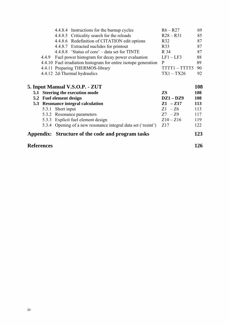
4.4.8.4 Instructions for the burnup cycles R6 – R27 69 4.4.8.5 Criticality search for the reloads R28 – R31 85 4.4.8.6 Redefinition of CITATION edit options R32 87 4.4.8.7 Extracted nuclides for printout R33 87 4.4.8.8 ‘Status of core’ – data set for TINTE R 34 87 4.4.9 Fuel power histogram for decay power evaluation LF1 – LF3 88 4.4.10 Fuel irradiation histogram for entire isotope generation P 89 4.4.11 Preparing THERMOS-library TTTT1 – TTTT5 90 4.4.12 2d-Thermal hydraulics TX1 – TX26 92
5. Input Manual V.S.O.P. - ZUT 108 5.1 Steering the execution mode ZS 108 5.2 Fuel element design DZ1 – DZ9 108 5.3 Resonance integral calculation Z1 – Z17 113 5.3.1 Short input Z1 – Z6 113 5.3.2 Resonance parameters Z7 – Z9 117 5.3.3 Explicit fuel element design Z10 – Z16 119 5.3.4 Opening of a new resonance integral data set (‘resint’) Z17 122
Appendix: Structure of the code and program tasks 123 References 126
v
List of Figures Page
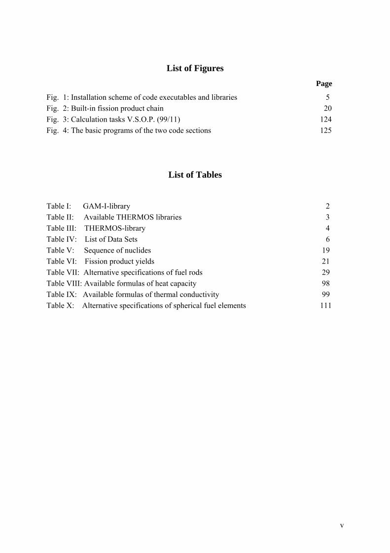
Fig. 1: Installation scheme of code executables and libraries 5 Fig. 2: Built-in fission product chain 20 Fig. 3: Calculation tasks V.S.O.P. (99/11) 124 Fig. 4: The basic programs of the two code sections 125
List of Tables
Table I: GAM-I-library 2 Table II: Available THERMOS libraries 3 Table III: THERMOS-library 4 Table IV: List of Data Sets 6 Table V: Sequence of nuclides 19 Table VI: Fission product yields 21 Table VII: Alternative specifications of fuel rods 29 Table VIII: Available formulas of heat capacity 98 Table IX: Available formulas of thermal conductivity 99 Table X: Alternative specifications of spherical fuel elements 111

vi
1
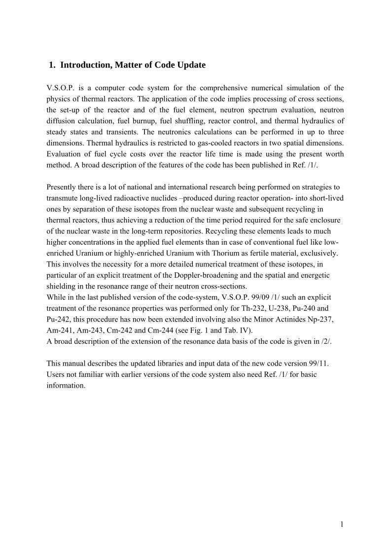
1. Introduction, Matter of Code Update V.S.O.P. is a computer code system for the comprehensive numerical simulation of the physics of thermal reactors. The application of the code implies processing of cross sections, the set-up of the reactor and of the fuel element, neutron spectrum evaluation, neutron diffusion calculation, fuel burnup, fuel shuffling, reactor control, and thermal hydraulics of steady states and transients. The neutronics calculations can be performed in up to three dimensions. Thermal hydraulics is restricted to gas-cooled reactors in two spatial dimensions. Evaluation of fuel cycle costs over the reactor life time is made using the present worth method. A broad description of the features of the code has been published in Ref. /1/. Presently there is a lot of national and international research being performed on strategies to transmute long-lived radioactive nuclides –produced during reactor operation- into short-lived ones by separation of these isotopes from the nuclear waste and subsequent recycling in thermal reactors, thus achieving a reduction of the time period required for the safe enclosure of the nuclear waste in the long-term repositories. Recycling these elements leads to much higher concentrations in the applied fuel elements than in case of conventional fuel like low-enriched Uranium or highly-enriched Uranium with Thorium as fertile material, exclusively. This involves the necessity for a more detailed numerical treatment of these isotopes, in particular of an explicit treatment of the Doppler-broadening and the spatial and energetic shielding in the resonance range of their neutron cross-sections. While in the last published version of the code-system, V.S.O.P. 99/09 /1/ such an explicit treatment of the resonance properties was performed only for Th-232, U-238, Pu-240 and Pu-242, this procedure has now been extended involving also the Minor Actinides Np-237, Am-241, Am-243, Cm-242 and Cm-244 (see Fig. 1 and Tab. IV). A broad description of the extension of the resonance data basis of the code is given in /2/. This manual describes the updated libraries and input data of the new code version 99/11. Users not familiar with earlier versions of the code system also need Ref. /1/ for basic information.
2
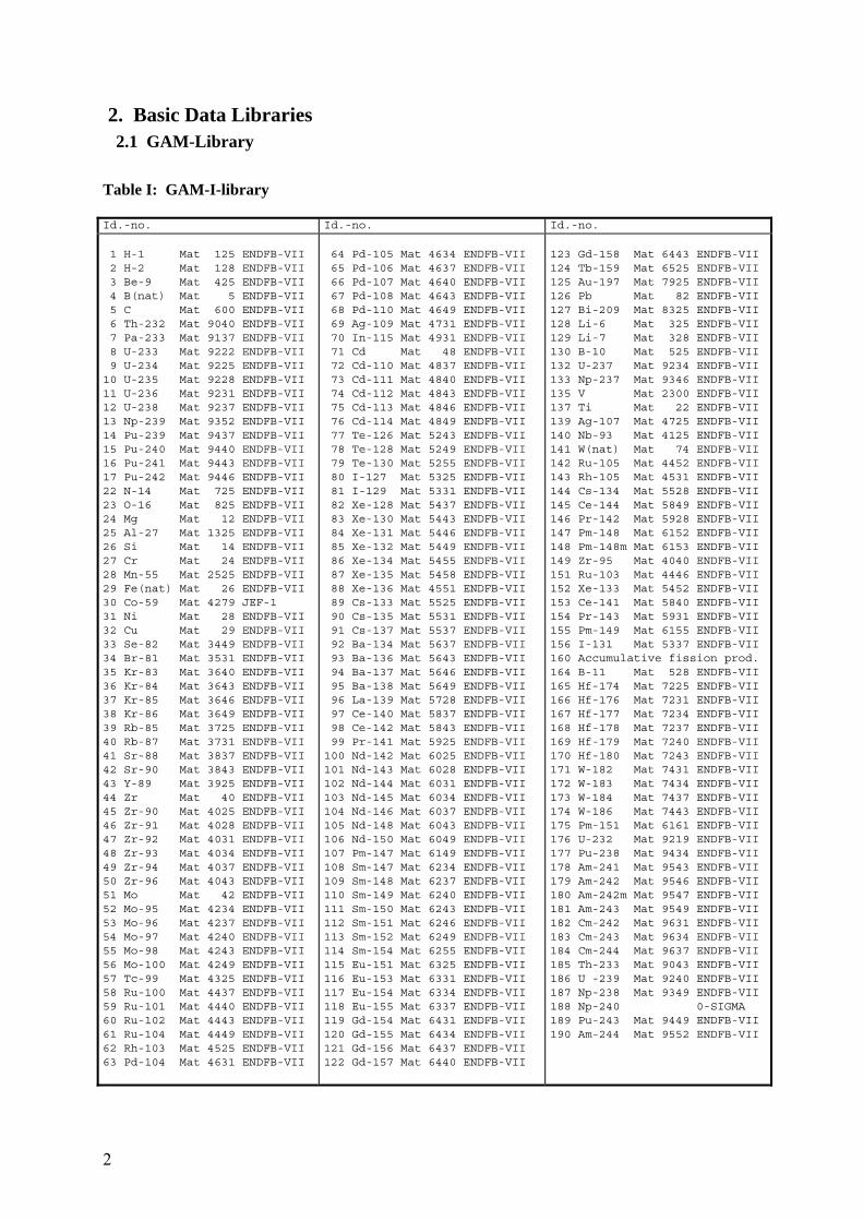
2. Basic Data Libraries 2.1 GAM-Library Table I: GAM-I-library Id.-no. Id.-no. Id.-no. 1 H-1 Mat 125 ENDFB-VII 2 H-2 Mat 128 ENDFB-VII 3 Be-9 Mat 425 ENDFB-VII 4 B(nat) Mat 5 ENDFB-VII 5 C Mat 600 ENDFB-VII 6 Th-232 Mat 9040 ENDFB-VII 7 Pa-233 Mat 9137 ENDFB-VII 8 U-233 Mat 9222 ENDFB-VII 9 U-234 Mat 9225 ENDFB-VII 10 U-235 Mat 9228 ENDFB-VII 11 U-236 Mat 9231 ENDFB-VII 12 U-238 Mat 9237 ENDFB-VII 13 Np-239 Mat 9352 ENDFB-VII 14 Pu-239 Mat 9437 ENDFB-VII 15 Pu-240 Mat 9440 ENDFB-VII 16 Pu-241 Mat 9443 ENDFB-VII 17 Pu-242 Mat 9446 ENDFB-VII 22 N-14 Mat 725 ENDFB-VII 23 O-16 Mat 825 ENDFB-VII 24 Mg Mat 12 ENDFB-VII 25 Al-27 Mat 1325 ENDFB-VII 26 Si Mat 14 ENDFB-VII 27 Cr Mat 24 ENDFB-VII 28 Mn-55 Mat 2525 ENDFB-VII 29 Fe(nat) Mat 26 ENDFB-VII 30 Co-59 Mat 4279 JEF-1 31 Ni Mat 28 ENDFB-VII 32 Cu Mat 29 ENDFB-VII 33 Se-82 Mat 3449 ENDFB-VII 34 Br-81 Mat 3531 ENDFB-VII 35 Kr-83 Mat 3640 ENDFB-VII 36 Kr-84 Mat 3643 ENDFB-VII 37 Kr-85 Mat 3646 ENDFB-VII 38 Kr-86 Mat 3649 ENDFB-VII 39 Rb-85 Mat 3725 ENDFB-VII 40 Rb-87 Mat 3731 ENDFB-VII 41 Sr-88 Mat 3837 ENDFB-VII 42 Sr-90 Mat 3843 ENDFB-VII 43 Y-89 Mat 3925 ENDFB-VII 44 Zr Mat 40 ENDFB-VII 45 Zr-90 Mat 4025 ENDFB-VII 46 Zr-91 Mat 4028 ENDFB-VII 47 Zr-92 Mat 4031 ENDFB-VII 48 Zr-93 Mat 4034 ENDFB-VII 49 Zr-94 Mat 4037 ENDFB-VII 50 Zr-96 Mat 4043 ENDFB-VII 51 Mo Mat 42 ENDFB-VII 52 Mo-95 Mat 4234 ENDFB-VII 53 Mo-96 Mat 4237 ENDFB-VII 54 Mo-97 Mat 4240 ENDFB-VII 55 Mo-98 Mat 4243 ENDFB-VII 56 Mo-100 Mat 4249 ENDFB-VII 57 Tc-99 Mat 4325 ENDFB-VII 58 Ru-100 Mat 4437 ENDFB-VII 59 Ru-101 Mat 4440 ENDFB-VII 60 Ru-102 Mat 4443 ENDFB-VII 61 Ru-104 Mat 4449 ENDFB-VII 62 Rh-103 Mat 4525 ENDFB-VII 63 Pd-104 Mat 4631 ENDFB-VII
64 Pd-105 Mat 4634 ENDFB-VII 65 Pd-106 Mat 4637 ENDFB-VII 66 Pd-107 Mat 4640 ENDFB-VII 67 Pd-108 Mat 4643 ENDFB-VII 68 Pd-110 Mat 4649 ENDFB-VII 69 Ag-109 Mat 4731 ENDFB-VII 70 In-115 Mat 4931 ENDFB-VII 71 Cd Mat 48 ENDFB-VII 72 Cd-110 Mat 4837 ENDFB-VII 73 Cd-111 Mat 4840 ENDFB-VII 74 Cd-112 Mat 4843 ENDFB-VII 75 Cd-113 Mat 4846 ENDFB-VII 76 Cd-114 Mat 4849 ENDFB-VII 77 Te-126 Mat 5243 ENDFB-VII 78 Te-128 Mat 5249 ENDFB-VII 79 Te-130 Mat 5255 ENDFB-VII 80 I-127 Mat 5325 ENDFB-VII 81 I-129 Mat 5331 ENDFB-VII 82 Xe-128 Mat 5437 ENDFB-VII 83 Xe-130 Mat 5443 ENDFB-VII 84 Xe-131 Mat 5446 ENDFB-VII 85 Xe-132 Mat 5449 ENDFB-VII 86 Xe-134 Mat 5455 ENDFB-VII 87 Xe-135 Mat 5458 ENDFB-VII 88 Xe-136 Mat 4551 ENDFB-VII 89 Cs-133 Mat 5525 ENDFB-VII 90 Cs-135 Mat 5531 ENDFB-VII 91 Cs-137 Mat 5537 ENDFB-VII 92 Ba-134 Mat 5637 ENDFB-VII 93 Ba-136 Mat 5643 ENDFB-VII 94 Ba-137 Mat 5646 ENDFB-VII 95 Ba-138 Mat 5649 ENDFB-VII 96 La-139 Mat 5728 ENDFB-VII 97 Ce-140 Mat 5837 ENDFB-VII 98 Ce-142 Mat 5843 ENDFB-VII 99 Pr-141 Mat 5925 ENDFB-VII 100 Nd-142 Mat 6025 ENDFB-VII 101 Nd-143 Mat 6028 ENDFB-VII 102 Nd-144 Mat 6031 ENDFB-VII 103 Nd-145 Mat 6034 ENDFB-VII 104 Nd-146 Mat 6037 ENDFB-VII 105 Nd-148 Mat 6043 ENDFB-VII 106 Nd-150 Mat 6049 ENDFB-VII 107 Pm-147 Mat 6149 ENDFB-VII 108 Sm-147 Mat 6234 ENDFB-VII 109 Sm-148 Mat 6237 ENDFB-VII 110 Sm-149 Mat 6240 ENDFB-VII 111 Sm-150 Mat 6243 ENDFB-VII 112 Sm-151 Mat 6246 ENDFB-VII 113 Sm-152 Mat 6249 ENDFB-VII 114 Sm-154 Mat 6255 ENDFB-VII 115 Eu-151 Mat 6325 ENDFB-VII 116 Eu-153 Mat 6331 ENDFB-VII 117 Eu-154 Mat 6334 ENDFB-VII 118 Eu-155 Mat 6337 ENDFB-VII 119 Gd-154 Mat 6431 ENDFB-VII 120 Gd-155 Mat 6434 ENDFB-VII 121 Gd-156 Mat 6437 ENDFB-VII 122 Gd-157 Mat 6440 ENDFB-VII
123 Gd-158 Mat 6443 ENDFB-VII 124 Tb-159 Mat 6525 ENDFB-VII 125 Au-197 Mat 7925 ENDFB-VII 126 Pb Mat 82 ENDFB-VII 127 Bi-209 Mat 8325 ENDFB-VII 128 Li-6 Mat 325 ENDFB-VII 129 Li-7 Mat 328 ENDFB-VII 130 B-10 Mat 525 ENDFB-VII 132 U-237 Mat 9234 ENDFB-VII 133 Np-237 Mat 9346 ENDFB-VII 135 V Mat 2300 ENDFB-VII 137 Ti Mat 22 ENDFB-VII 139 Ag-107 Mat 4725 ENDFB-VII 140 Nb-93 Mat 4125 ENDFB-VII 141 W(nat) Mat 74 ENDFB-VII 142 Ru-105 Mat 4452 ENDFB-VII 143 Rh-105 Mat 4531 ENDFB-VII 144 Cs-134 Mat 5528 ENDFB-VII 145 Ce-144 Mat 5849 ENDFB-VII 146 Pr-142 Mat 5928 ENDFB-VII 147 Pm-148 Mat 6152 ENDFB-VII 148 Pm-148m Mat 6153 ENDFB-VII 149 Zr-95 Mat 4040 ENDFB-VII 151 Ru-103 Mat 4446 ENDFB-VII 152 Xe-133 Mat 5452 ENDFB-VII 153 Ce-141 Mat 5840 ENDFB-VII 154 Pr-143 Mat 5931 ENDFB-VII 155 Pm-149 Mat 6155 ENDFB-VII 156 I-131 Mat 5337 ENDFB-VII 160 Accumulative fission prod. 164 B-11 Mat 528 ENDFB-VII 165 Hf-174 Mat 7225 ENDFB-VII 166 Hf-176 Mat 7231 ENDFB-VII 167 Hf-177 Mat 7234 ENDFB-VII 168 Hf-178 Mat 7237 ENDFB-VII 169 Hf-179 Mat 7240 ENDFB-VII 170 Hf-180 Mat 7243 ENDFB-VII 171 W-182 Mat 7431 ENDFB-VII 172 W-183 Mat 7434 ENDFB-VII 173 W-184 Mat 7437 ENDFB-VII 174 W-186 Mat 7443 ENDFB-VII 175 Pm-151 Mat 6161 ENDFB-VII 176 U-232 Mat 9219 ENDFB-VII 177 Pu-238 Mat 9434 ENDFB-VII 178 Am-241 Mat 9543 ENDFB-VII 179 Am-242 Mat 9546 ENDFB-VII 180 Am-242m Mat 9547 ENDFB-VII 181 Am-243 Mat 9549 ENDFB-VII 182 Cm-242 Mat 9631 ENDFB-VII 183 Cm-243 Mat 9634 ENDFB-VII 184 Cm-244 Mat 9637 ENDFB-VII 185 Th-233 Mat 9043 ENDFB-VII 186 U -239 Mat 9240 ENDFB-VII 187 Np-238 Mat 9349 ENDFB-VII 188 Np-240 0-SIGMA 189 Pu-243 Mat 9449 ENDFB-VII 190 Am-244 Mat 9552 ENDFB-VII
3
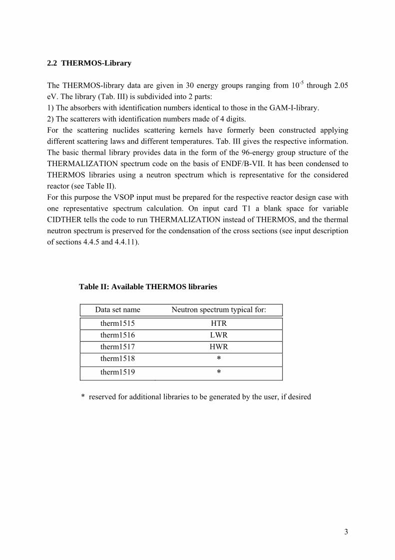
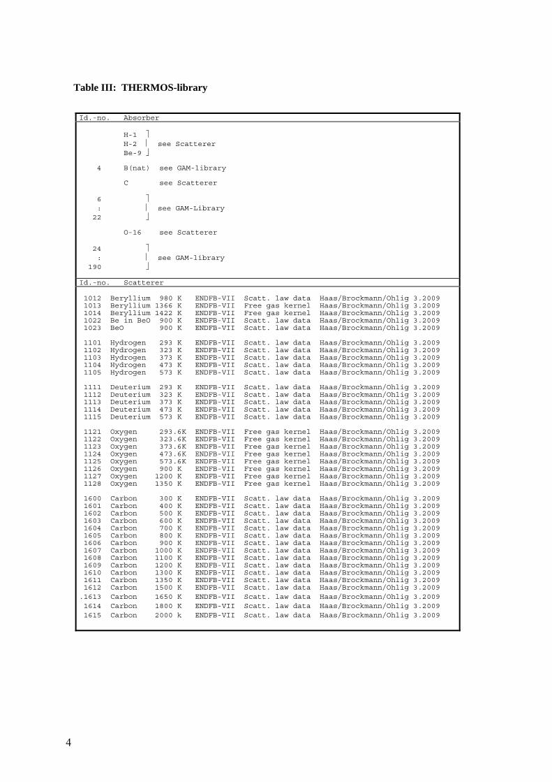
2.2 THERMOS-Library The THERMOS-library data are given in 30 energy groups ranging from 10-5 through 2.05 eV. The library (Tab. III) is subdivided into 2 parts: 1) The absorbers with identification numbers identical to those in the GAM-I-library. 2) The scatterers with identification numbers made of 4 digits. For the scattering nuclides scattering kernels have formerly been constructed applying different scattering laws and different temperatures. Tab. III gives the respective information. The basic thermal library provides data in the form of the 96-energy group structure of the THERMALIZATION spectrum code on the basis of ENDF/B-VII. It has been condensed to THERMOS libraries using a neutron spectrum which is representative for the considered reactor (see Table II). For this purpose the VSOP input must be prepared for the respective reactor design case with one representative spectrum calculation. On input card T1 a blank space for variable CIDTHER tells the code to run THERMALIZATION instead of THERMOS, and the thermal neutron spectrum is preserved for the condensation of the cross sections (see input description of sections 4.4.5 and 4.4.11). Table II: Available THERMOS libraries
Data set name Neutron spectrum typical for:
therm1515 HTR therm1516 LWR therm1517 HWR therm1518 * therm1519 *
* reserved for additional libraries to be generated by the user, if desired
4
Table III: THERMOS-library
Id.-no. Absorber H-1 ⎤ H-2 ⎥ see Scatterer Be-9 ⎦ 4 B(nat) see GAM-library C see Scatterer 6 ⎤ : ⎥ see GAM-Library 22 ⎦ O-16 see Scatterer 24 ⎤ : ⎥ see GAM-library 190 ⎦ Id.-no. Scatterer 1012 Beryllium 980 K ENDFB-VII Scatt. law data Haas/Brockmann/Ohlig 3.2009 1013 Beryllium 1366 K ENDFB-VII Free gas kernel Haas/Brockmann/Ohlig 3.2009 1014 Beryllium 1422 K ENDFB-VII Free gas kernel Haas/Brockmann/Ohlig 3.2009 1022 Be in BeO 900 K ENDFB-VII Scatt. law data Haas/Brockmann/Ohlig 3.2009 1023 BeO 900 K ENDFB-VII Scatt. law data Haas/Brockmann/Ohlig 3.2009 1101 Hydrogen 293 K ENDFB-VII Scatt. law data Haas/Brockmann/Ohlig 3.2009 1102 Hydrogen 323 K ENDFB-VII Scatt. law data Haas/Brockmann/Ohlig 3.2009 1103 Hydrogen 373 K ENDFB-VII Scatt. law data Haas/Brockmann/Ohlig 3.2009 1104 Hydrogen 473 K ENDFB-VII Scatt. law data Haas/Brockmann/Ohlig 3.2009 1105 Hydrogen 573 K ENDFB-VII Scatt. law data Haas/Brockmann/Ohlig 3.2009 1111 Deuterium 293 K ENDFB-VII Scatt. law data Haas/Brockmann/Ohlig 3.2009 1112 Deuterium 323 K ENDFB-VII Scatt. law data Haas/Brockmann/Ohlig 3.2009 1113 Deuterium 373 K ENDFB-VII Scatt. law data Haas/Brockmann/Ohlig 3.2009 1114 Deuterium 473 K ENDFB-VII Scatt. law data Haas/Brockmann/Ohlig 3.2009 1115 Deuterium 573 K ENDFB-VII Scatt. law data Haas/Brockmann/Ohlig 3.2009 1121 Oxygen 293.6K ENDFB-VII Free gas kernel Haas/Brockmann/Ohlig 3.2009 1122 Oxygen 323.6K ENDFB-VII Free gas kernel Haas/Brockmann/Ohlig 3.2009 1123 Oxygen 373.6K ENDFB-VII Free gas kernel Haas/Brockmann/Ohlig 3.2009 1124 Oxygen 473.6K ENDFB-VII Free gas kernel Haas/Brockmann/Ohlig 3.2009 1125 Oxygen 573.6K ENDFB-VII Free gas kernel Haas/Brockmann/Ohlig 3.2009 1126 Oxygen 900 K ENDFB-VII Free gas kernel Haas/Brockmann/Ohlig 3.2009 1127 Oxygen 1200 K ENDFB-VII Free gas kernel Haas/Brockmann/Ohlig 3.2009 1128 Oxygen 1350 K ENDFB-VII Free gas kernel Haas/Brockmann/Ohlig 3.2009 1600 Carbon 300 K ENDFB-VII Scatt. law data Haas/Brockmann/Ohlig 3.2009 1601 Carbon 400 K ENDFB-VII Scatt. law data Haas/Brockmann/Ohlig 3.2009 1602 Carbon 500 K ENDFB-VII Scatt. law data Haas/Brockmann/Ohlig 3.2009 1603 Carbon 600 K ENDFB-VII Scatt. law data Haas/Brockmann/Ohlig 3.2009 1604 Carbon 700 K ENDFB-VII Scatt. law data Haas/Brockmann/Ohlig 3.2009 1605 Carbon 800 K ENDFB-VII Scatt. law data Haas/Brockmann/Ohlig 3.2009 1606 Carbon 900 K ENDFB-VII Scatt. law data Haas/Brockmann/Ohlig 3.2009 1607 Carbon 1000 K ENDFB-VII Scatt. law data Haas/Brockmann/Ohlig 3.2009 1608 Carbon 1100 K ENDFB-VII Scatt. law data Haas/Brockmann/Ohlig 3.2009 1609 Carbon 1200 K ENDFB-VII Scatt. law data Haas/Brockmann/Ohlig 3.2009 1610 Carbon 1300 K ENDFB-VII Scatt. law data Haas/Brockmann/Ohlig 3.2009 1611 Carbon 1350 K ENDFB-VII Scatt. law data Haas/Brockmann/Ohlig 3.2009 1612 Carbon 1500 K ENDFB-VII Scatt. law data Haas/Brockmann/Ohlig 3.2009 .1613 Carbon 1650 K ENDFB-VII Scatt. law data Haas/Brockmann/Ohlig 3.2009 1614 Carbon 1800 K ENDFB-VII Scatt. law data Haas/Brockmann/Ohlig 3.2009 1615 Carbon 2000 k ENDFB-VII Scatt. law data Haas/Brockmann/Ohlig 3.2009
5
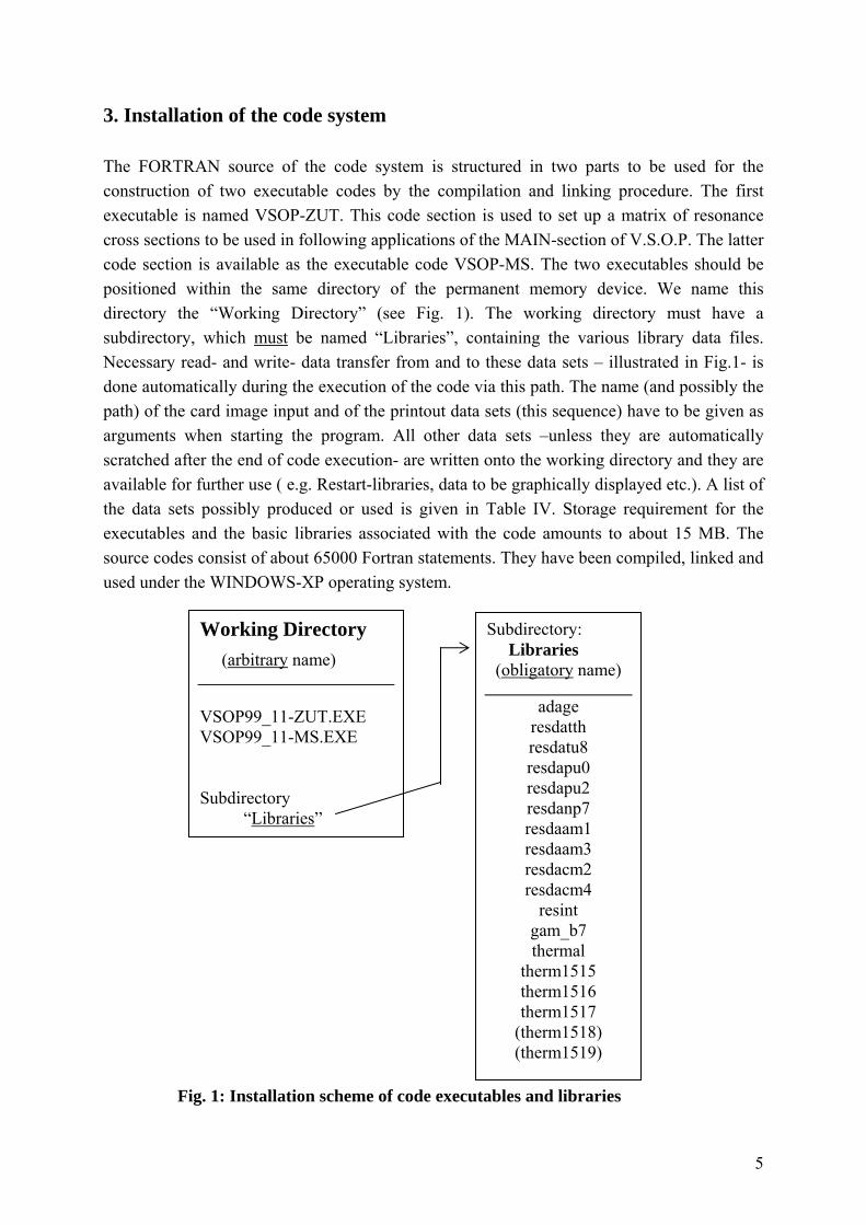
3. Installation of the code system The FORTRAN source of the code system is structured in two parts to be used for the construction of two executable codes by the compilation and linking procedure. The first executable is named VSOP-ZUT. This code section is used to set up a matrix of resonance cross sections to be used in following applications of the MAIN-section of V.S.O.P. The latter code section is available as the executable code VSOP-MS. The two executables should be positioned within the same directory of the permanent memory device. We name this directory the “Working Directory” (see Fig. 1). The working directory must have a subdirectory, which must be named “Libraries”, containing the various library data files. Necessary read- and write- data transfer from and to these data sets – illustrated in Fig.1- is done automatically during the execution of the code via this path. The name (and possibly the path) of the card image input and of the printout data sets (this sequence) have to be given as arguments when starting the program. All other data sets –unless they are automatically scratched after the end of code execution- are written onto the working directory and they are available for further use ( e.g. Restart-libraries, data to be graphically displayed etc.). A list of the data sets possibly produced or used is given in Table IV. Storage requirement for the executables and the basic libraries associated with the code amounts to about 15 MB. The source codes consist of about 65000 Fortran statements. They have been compiled, linked and used under the WINDOWS-XP operating system. Fig. 1: Installation scheme of code executables and libraries
Working Directory (arbitrary name)
VSOP99_11-ZUT.EXE VSOP99_11-MS.EXE Subdirectory “Libraries”
Subdirectory: Libraries (obligatory name)
adage resdatth resdatu8 resdapu0 resdapu2 resdanp7 resdaam1 resdaam3 resdacm2 resdacm4
resint gam_b7 thermal
therm1515 therm1516 therm1517
(therm1518) (therm1519)
6
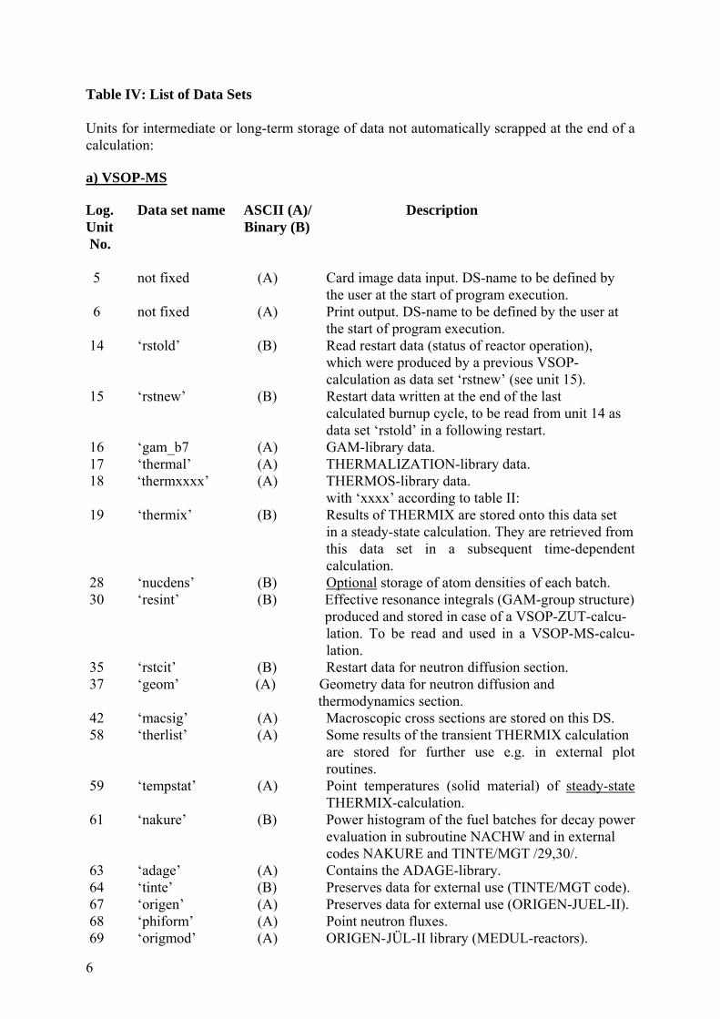
Table IV: List of Data Sets Units for intermediate or long-term storage of data not automatically scrapped at the end of a calculation: a) VSOP-MS Log. Data set name ASCII (A)/ Description Unit Binary (B) No. 5 not fixed (A) Card image data input. DS-name to be defined by
the user at the start of program execution. 6 not fixed (A) Print output. DS-name to be defined by the user at the start of program execution. 14 ‘rstold’ (B) Read restart data (status of reactor operation), which were produced by a previous VSOP- calculation as data set ‘rstnew’ (see unit 15). 15 ‘rstnew’ (B) Restart data written at the end of the last calculated burnup cycle, to be read from unit 14 as data set ‘rstold’ in a following restart. 16 ‘gam_b7 (A) GAM-library data. 17 ‘thermal’ (A) THERMALIZATION-library data. 18 ‘thermxxxx’ (A) THERMOS-library data. with ‘xxxx’ according to table II: 19 ‘thermix’ (B) Results of THERMIX are stored onto this data set in a steady-state calculation. They are retrieved from
this data set in a subsequent time-dependent calculation.
28 ‘nucdens’ (B) Optional storage of atom densities of each batch. 30 ‘resint’ (B) Effective resonance integrals (GAM-group structure) produced and stored in case of a VSOP-ZUT-calcu-
lation. To be read and used in a VSOP-MS-calcu- lation.
35 ‘rstcit’ (B) Restart data for neutron diffusion section. 37 ‘geom’ (A) Geometry data for neutron diffusion and thermodynamics section. 42 ‘macsig’ (A) Macroscopic cross sections are stored on this DS. 58 ‘therlist’ (A) Some results of the transient THERMIX calculation
are stored for further use e.g. in external plot routines.
59 ‘tempstat’ (A) Point temperatures (solid material) of steady-state THERMIX-calculation. 61 ‘nakure’ (B) Power histogram of the fuel batches for decay power evaluation in subroutine NACHW and in external codes NAKURE and TINTE/MGT /29,30/. 63 ‘adage’ (A) Contains the ADAGE-library. 64 ‘tinte’ (B) Preserves data for external use (TINTE/MGT code). 67 ‘origen’ (A) Preserves data for external use (ORIGEN-JUEL-II). 68 ‘phiform’ (A) Point neutron fluxes. 69 ‘origmod’ (A) ORIGEN- JÜL-II library (MEDUL-reactors).
7
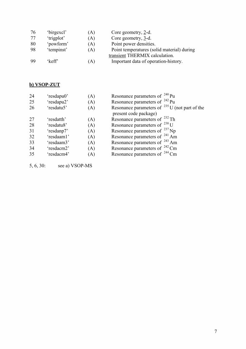
76 ‘birgexcl’ (A) Core geometry, 2-d. 77 ‘trigplot’ (A) Core geometry, 3-d. 80 ‘powform’ (A) Point power densities. 98 ‘tempinst’ (A) Point temperatures (solid material) during transient THERMIX calculation. 99 ‘keff’ (A) Important data of operation-history.
b) VSOP-ZUT
24 ‘resdapu0’ (A) Resonance parameters of 240 Pu 25 ‘resdapu2’ (A) Resonance parameters of 242 Pu 26 ‘resdatu5’ (A) Resonance parameters of 235 U (not part of the
present code package) 27 ‘resdatth’ (A) Resonance parameters of 232 Th 28 ‘resdatu8’ (A) Resonance parameters of 238 U 31 ‘resdanp7’ (A) Resonance parameters of 237 Np 32 ‘resdaam1’ (A) Resonance parameters of 241 Am 33 ‘resdaam3’ (A) Resonance parameters of 243 Am 34 ‘resdacm2’ (A) Resonance parameters of 242 Cm 35 ‘resdacm4’ (A) Resonance parameters of 244 Cm 5, 6, 30: see a) VSOP-MS

8
9
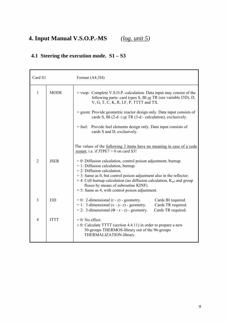
4. Input Manual V.S.O.P.-MS (log. unit 5) 4.1 Steering the execution mode. S1 – S3
Card S1 Format (A4,3I4) 1 2 3 4
MODE JSER I3D ITTT
= vsop: Complete V.S.O.P.-calculation. Data input may consist of the following parts: card types S, BI or TR (see variable I3D), D, V, G, T, C, K, R, LF, P, TTTT and TX. = geom: Provide geometric reactor design only. Data input consists of cards S, BI (2-d -) or TR (3-d - calculation), exclusively. = fuel: Provide fuel elements design only. Data input consists of cards S and D, exclusively. The values of the following 3 items have no meaning in case of a code restart, i.e. if JTPE7 > 0 on card S3! = 0: Diffusion calculation, control poison adjustment, burnup. = 1: Diffusion calculation, burnup. = 2: Diffusion calculation. = 3: Same as 0, but control poison adjustment also in the reflector. = 4: Cell burnup calculation (no diffusion calculation, Kinf and group fluxes by means of subroutine KINF). = 5: Same as 4, with control poison adjustment. = 0: 2-dimensional (r - z) - geometry. Cards BI required. = 1: 3-dimensional (x - y- z) - geometry. Cards TR required. = 2: 3-dimensional (Φ - r - z) - geometry. Cards TR required. = 0: No effect. > 0: Calculate TTTT (section 4.4.11) in order to prepare a new 30-groups THERMOS-library out of the 96-groups THERMALIZATION-library.
10
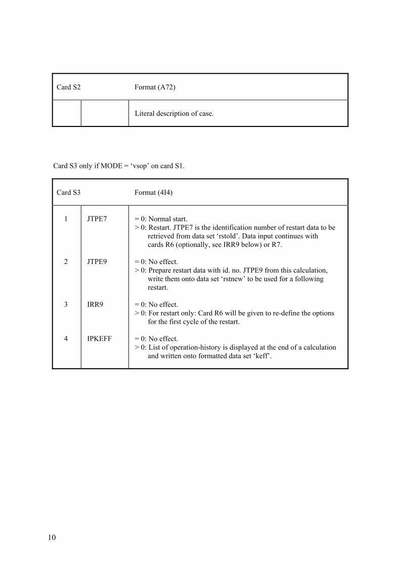
Card S2 Format (A72)
Literal description of case.
Card S3 only if MODE = ‘vsop’ on card S1.
Card S3 Format (4I4) 1 2 3 4
JTPE7 JTPE9 IRR9 IPKEFF
= 0: Normal start. > 0: Restart. JTPE7 is the identification number of restart data to be retrieved from data set ‘rstold’. Data input continues with cards R6 (optionally, see IRR9 below) or R7. = 0: No effect. > 0: Prepare restart data with id. no. JTPE9 from this calculation, write them onto data set ‘rstnew’ to be used for a following restart. = 0: No effect. > 0: For restart only: Card R6 will be given to re-define the options for the first cycle of the restart. = 0: No effect. > 0: List of operation-history is displayed at the end of a calculation and written onto formatted data set ‘keff’.
11
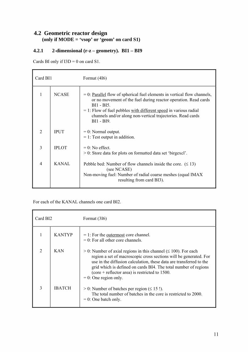
4.2 Geometric reactor design (only if MODE = ‘vsop’ or ‘geom’ on card S1) 4.2.1 2-dimensional (r-z – geometry). BI1 – BI9 Cards BI only if I3D = 0 on card S1.
Card BI1 Format (4I6) 1 2 3 4
NCASE IPUT IPLOT KANAL
= 0: Parallel flow of spherical fuel elements in vertical flow channels, or no movement of the fuel during reactor operation. Read cards BI1 - BI5. = 1: Flow of fuel pebbles with different speed in various radial channels and/or along non-vertical trajectories. Read cards BI1 - BI9. = 0: Normal output. = 1: Test output in addition. = 0: No effect. > 0: Store data for plots on formatted data set ‘birgexcl’. Pebble bed: Number of flow channels inside the core. (≤ 13) (see NCASE) Non-moving fuel: Number of radial coarse meshes (equal IMAX resulting from card BI3).
For each of the KANAL channels one card BI2.
Card BI2 Format (3I6) 1 2 3
KANTYP KAN IBATCH
= 1: For the outermost core channel. = 0: For all other core channels. > 0: Number of axial regions in this channel (≤ 100). For each region a set of macroscopic cross sections will be generated. For use in the diffusion calculation, these data are transferred to the grid which is defined on cards BI4. The total number of regions (core + reflector area) is restricted to 1500. = 0: One region only. > 0: Number of batches per region (≤ 15 !). The total number of batches in the core is restricted to 2000. = 0: One batch only.
12
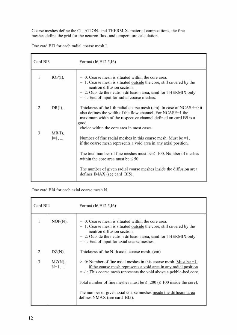
Coarse meshes define the CITATION- and THERMIX- material compositions, the fine meshes define the grid for the neutron flux- and temperature calculation. One card BI3 for each radial coarse mesh I.
Card BI3 Format (I6,E12.5,I6) 1 2 3
IOP(I), DR(I), MR(I), I=1, ...
= 0: Coarse mesh is situated within the core area. = 1: Coarse mesh is situated outside the core, still covered by the neutron diffusion section. = 2: Outside the neutron diffusion area, used for THERMIX only. = -1: End of input for radial coarse meshes. Thickness of the I-th radial coarse mesh (cm). In case of NCASE=0 it also defines the width of the flow channel. For NCASE=1 the maximum width of the respective channel defined on card B9 is a good choice within the core area in most cases. Number of fine radial meshes in this coarse mesh. Must be =1, if the coarse mesh represents a void area in any axial position. The total number of fine meshes must be ≤ 100. Number of meshes within the core area must be ≤ 50 The number of given radial coarse meshes inside the diffusion area defines IMAX (see card BI5).
One card BI4 for each axial coarse mesh N.
Card BI4 Format (I6,E12.5,I6) 1 2 3
NOP(N), DZ(N), MZ(N), N=1, ...
= 0: Coarse mesh is situated within the core area. = 1: Coarse mesh is situated outside the core, still covered by the neutron diffusion section. = 2: Outside the neutron diffusion area, used for THERMIX only. = -1: End of input for axial coarse meshes. Thickness of the N-th axial coarse mesh. (cm) > 0: Number of fine axial meshes in this coarse mesh. Must be =1, if the coarse mesh represents a void area in any radial position. = -1: This coarse mesh represents the void above a pebble-bed core. Total number of fine meshes must be ≤ 200 (≤ 100 inside the core). The number of given axial coarse meshes inside the diffusion area defines NMAX (see card BI5).
13
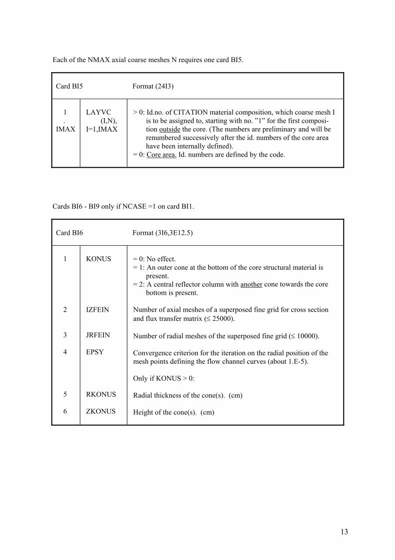
Each of the NMAX axial coarse meshes N requires one card BI5.
Card BI5 Format (24I3) 1 . IMAX
LAYVC (I,N), I=1,IMAX
> 0: Id.no. of CITATION material composition, which coarse mesh I is to be assigned to, starting with no. ”1” for the first composi- tion outside the core. (The numbers are preliminary and will be renumbered successively after the id. numbers of the core area have been internally defined). = 0: Core area. Id. numbers are defined by the code.
Cards BI6 - BI9 only if NCASE =1 on card BI1.
Card BI6 Format (3I6,3E12.5) 1 2 3 4 5 6
KONUS IZFEIN JRFEIN EPSY RKONUS ZKONUS
= 0: No effect. = 1: An outer cone at the bottom of the core structural material is present. = 2: A central reflector column with another cone towards the core bottom is present. Number of axial meshes of a superposed fine grid for cross section and flux transfer matrix (≤ 25000). Number of radial meshes of the superposed fine grid (≤ 10000). Convergence criterion for the iteration on the radial position of the mesh points defining the flow channel curves (about 1.E-5). Only if KONUS > 0: Radial thickness of the cone(s). (cm) Height of the cone(s). (cm)
14
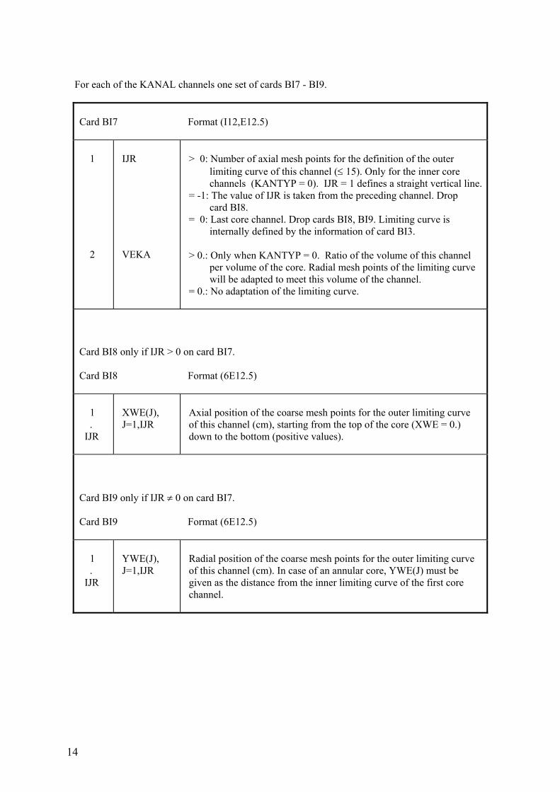
For each of the KANAL channels one set of cards BI7 - BI9.
Card BI7 Format (I12,E12.5) 1 2
IJR VEKA
> 0: Number of axial mesh points for the definition of the outer limiting curve of this channel (≤ 15). Only for the inner core channels (KANTYP = 0). IJR = 1 defines a straight vertical line. = -1: The value of IJR is taken from the preceding channel. Drop card BI8. = 0: Last core channel. Drop cards BI8, BI9. Limiting curve is internally defined by the information of card BI3. > 0.: Only when KANTYP = 0. Ratio of the volume of this channel per volume of the core. Radial mesh points of the limiting curve will be adapted to meet this volume of the channel. = 0.: No adaptation of the limiting curve.
Card BI8 only if IJR > 0 on card BI7. Card BI8 Format (6E12.5) 1 . IJR
XWE(J), J=1,IJR
Axial position of the coarse mesh points for the outer limiting curve of this channel (cm), starting from the top of the core (XWE = 0.) down to the bottom (positive values).
Card BI9 only if IJR ≠ 0 on card BI7. Card BI9 Format (6E12.5) 1 . IJR
YWE(J), J=1,IJR
Radial position of the coarse mesh points for the outer limiting curve of this channel (cm). In case of an annular core, YWE(J) must be given as the distance from the inner limiting curve of the first core channel.
15
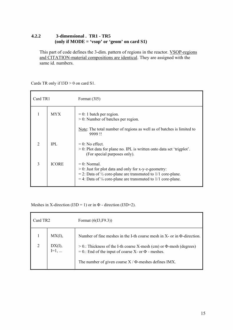
4.2.2 3-dimensional . TR1 - TR5 (only if MODE = ‘vsop’ or ‘geom’ on card S1) This part of code defines the 3-dim. pattern of regions in the reactor. VSOP-regions and CITATION-material compositions are identical. They are assigned with the same id. numbers. Cards TR only if I3D > 0 on card S1.
Card TR1 Format (3I5) 1 2 3
MYX IPL ICORE
= 0: 1 batch per region. > 0: Number of batches per region. Note: The total number of regions as well as of batches is limited to 9999 !! = 0: No effect. > 0: Plot data for plane no. IPL is written onto data set ‘trigplot’. (For special purposes only). = 0: Normal. > 0: Just for plot data and only for x-y-z-geometry: = 2: Data of ½ core-plane are transmuted to 1/1 core-plane. = 4: Data of ¼ core-plane are transmuted to 1/1 core-plane.
Meshes in X-direction (I3D = 1) or in Φ - direction (I3D=2).
Card TR2 Format (6(I3,F9.3)) 1 2
MX(I), DX(I), I=1, ...
Number of fine meshes in the I-th coarse mesh in X- or in Φ-direction. > 0.: Thickness of the I-th coarse X-mesh (cm) or Φ-mesh (degrees) = 0.: End of the input of coarse X- or Φ - meshes. The number of given coarse X / Φ-meshes defines IMX.
16
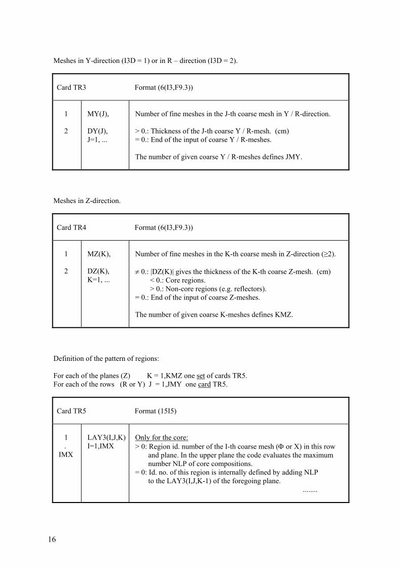
Meshes in Y-direction (I3D = 1) or in R – direction (I3D = 2).
Card TR3 Format (6(I3,F9.3)) 1 2
MY(J), DY(J), J=1, ...
Number of fine meshes in the J-th coarse mesh in Y / R-direction. > 0.: Thickness of the J-th coarse Y / R-mesh. (cm) = 0.: End of the input of coarse Y / R-meshes. The number of given coarse Y / R-meshes defines JMY.
Meshes in Z-direction.
Card TR4 Format (6(I3,F9.3)) 1 2
MZ(K), DZ(K), K=1, ...
Number of fine meshes in the K-th coarse mesh in Z-direction (≥2). ≠ 0.: |DZ(K)| gives the thickness of the K-th coarse Z-mesh. (cm) < 0.: Core regions. > 0.: Non-core regions (e.g. reflectors). = 0.: End of the input of coarse Z-meshes. The number of given coarse K-meshes defines KMZ.
Definition of the pattern of regions: For each of the planes (Z) K = 1,KMZ one set of cards TR5. For each of the rows (R or Y) J = 1,JMY one card TR5.
Card TR5 Format (15I5) 1 . IMX
LAY3(I,J,K) I=1,IMX
Only for the core: > 0: Region id. number of the I-th coarse mesh (Φ or X) in this row and plane. In the upper plane the code evaluates the maximum number NLP of core compositions. = 0: Id. no. of this region is internally defined by adding NLP to the LAY3(I,J,K-1) of the foregoing plane. ........

17
Continuation of card TR5
Only for the non-core-compositions (reflectors etc.): < 0: Id. no. of this composition is internally defined by adding the maximum number of core compositions to the absolute of |LAY3(I,J,K)|. Reflector id. numbers must be given in an un- broken sequence starting with “-1”.
18
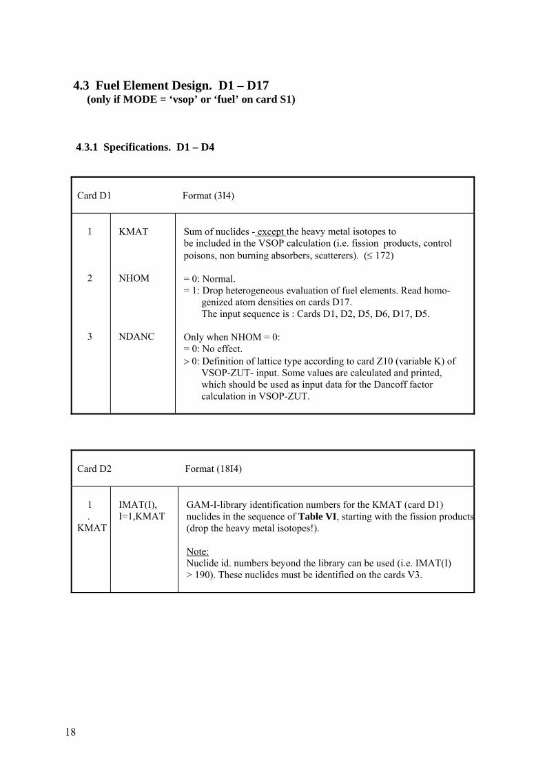
4.3 Fuel Element Design. D1 – D17 (only if MODE = ‘vsop’ or ‘fuel’ on card S1) 4.3.1 Specifications. D1 – D4
Card D1 Format (3I4) 1 2 3
KMAT NHOM NDANC
Sum of nuclides - except the heavy metal isotopes to be included in the VSOP calculation (i.e. fission products, control poisons, non burning absorbers, scatterers). (≤ 172) = 0: Normal. = 1: Drop heterogeneous evaluation of fuel elements. Read homo- genized atom densities on cards D17. The input sequence is : Cards D1, D2, D5, D6, D17, D5. Only when NHOM = 0: = 0: No effect. > 0: Definition of lattice type according to card Z10 (variable K) of VSOP-ZUT- input. Some values are calculated and printed, which should be used as input data for the Dancoff factor calculation in VSOP-ZUT.
Card D2 Format (18I4) 1 . KMAT
IMAT(I), I=1,KMAT
GAM-I-library identification numbers for the KMAT (card D1) nuclides in the sequence of Table VI, starting with the fission products (drop the heavy metal isotopes!). Note: Nuclide id. numbers beyond the library can be used (i.e. IMAT(I) > 190). These nuclides must be identified on the cards V3.
19
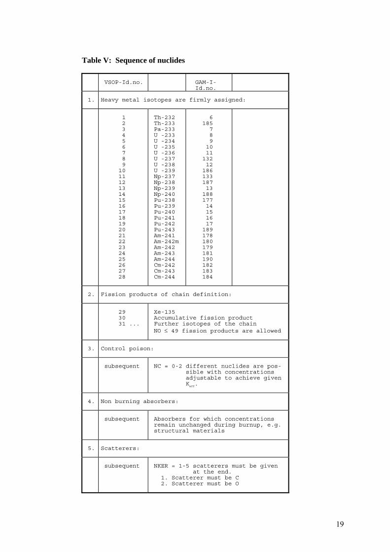
Table V: Sequence of nuclides
VSOP-Id.no.
GAM-I- Id.no.
1.
Heavy metal isotopes are firmly assigned:
1 2 3 4 5 6 7 8 9 10 11 12 13 14 15 16 17 18 19 20 21 22 23 24 25 26 27 28
Th-232 Th-233 Pa-233 U -233 U -234 U -235 U -236 U -237 U -238 U -239 Np-237 Np-238 Np-239 Np-240 Pu-238 Pu-239 Pu-240 Pu-241 Pu-242 Pu-243 Am-241 Am-242m Am-242 Am-243 Am-244 Cm-242 Cm-243 Cm-244
6 185 7 8 9 10 11 132 12 186 133 187 13 188 177 14 15 16 17 189 178 180 179 181 190 182 183 184
2.
Fission products of chain definition:
29 30 31 ...
Xe-135 Accumulative fission product Further isotopes of the chain NO ≤ 49 fission products are allowed
3.
Control poison:
subsequent
NC = 0-2 different nuclides are pos- sible with concentrations adjustable to achieve given K
eff.
4.
Non burning absorbers:
subsequent
Absorbers for which concentrations remain unchanged during burnup, e.g. structural materials
5.
Scatterers:
subsequent
NKER = 1-5 scatterers must be given at the end. 1. Scatterer must be C 2. Scatterer must be O
20
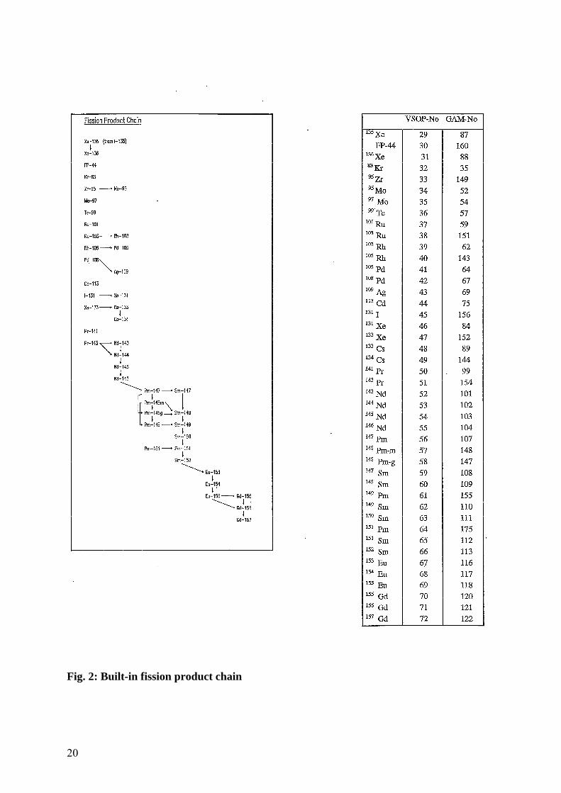
Fig. 2: Built-in fission product chain
21
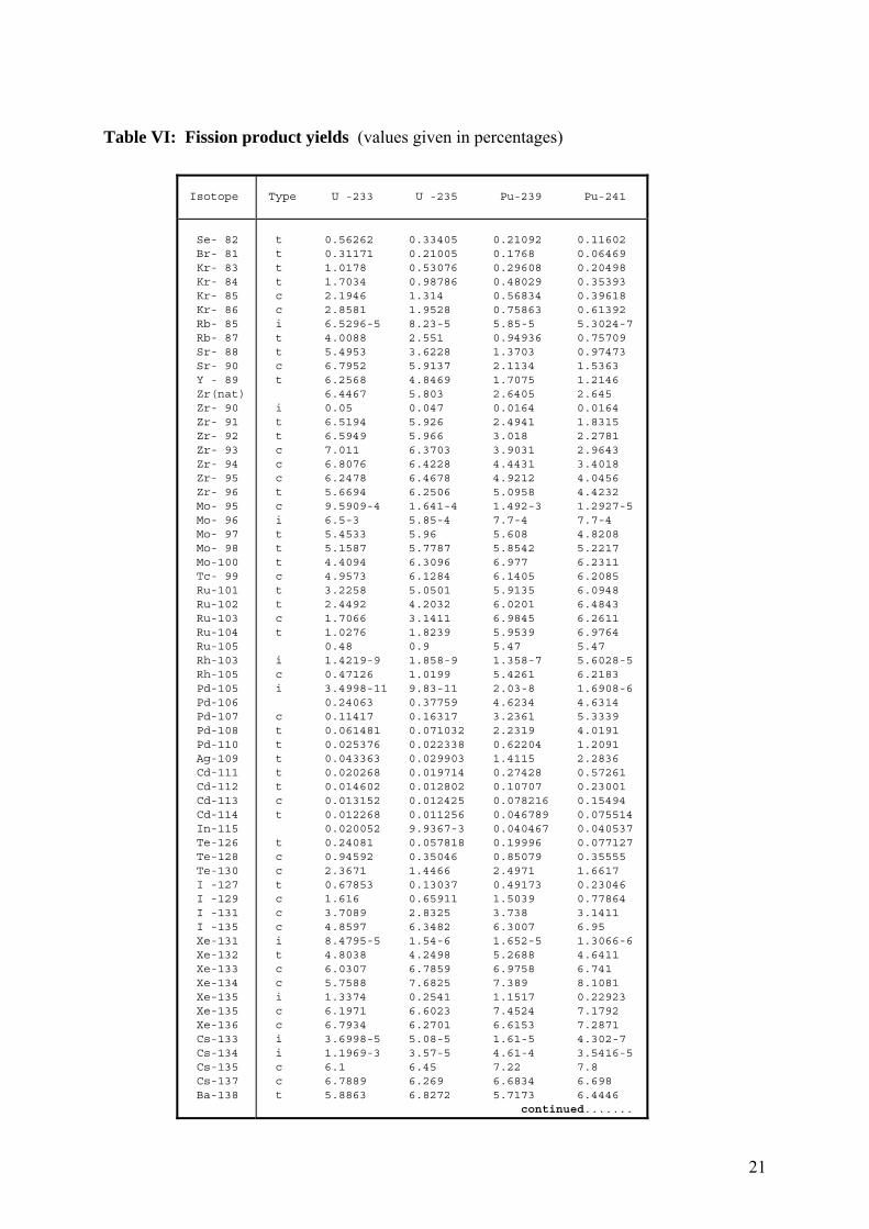
Table VI: Fission product yields (values given in percentages)
Isotope
Type U -233 U -235 Pu-239 Pu-241
Se- 82 Br- 81 Kr- 83 Kr- 84 Kr- 85 Kr- 86 Rb- 85 Rb- 87 Sr- 88 Sr- 90 Y - 89 Zr(nat) Zr- 90 Zr- 91 Zr- 92 Zr- 93 Zr- 94 Zr- 95 Zr- 96 Mo- 95 Mo- 96 Mo- 97 Mo- 98 Mo-100 Tc- 99 Ru-101 Ru-102 Ru-103 Ru-104 Ru-105 Rh-103 Rh-105 Pd-105 Pd-106 Pd-107 Pd-108 Pd-110 Ag-109 Cd-111 Cd-112 Cd-113 Cd-114 In-115 Te-126 Te-128 Te-130 I -127 I -129 I -131 I -135 Xe-131 Xe-132 Xe-133 Xe-134 Xe-135 Xe-135 Xe-136 Cs-133 Cs-134 Cs-135 Cs-137 Ba-138
t 0.56262 0.33405 0.21092 0.11602 t 0.31171 0.21005 0.1768 0.06469 t 1.0178 0.53076 0.29608 0.20498 t 1.7034 0.98786 0.48029 0.35393 c 2.1946 1.314 0.56834 0.39618 c 2.8581 1.9528 0.75863 0.61392 i 6.5296-5 8.23-5 5.85-5 5.3024-7 t 4.0088 2.551 0.94936 0.75709 t 5.4953 3.6228 1.3703 0.97473 c 6.7952 5.9137 2.1134 1.5363 t 6.2568 4.8469 1.7075 1.2146 6.4467 5.803 2.6405 2.645 i 0.05 0.047 0.0164 0.0164 t 6.5194 5.926 2.4941 1.8315 t 6.5949 5.966 3.018 2.2781 c 7.011 6.3703 3.9031 2.9643 c 6.8076 6.4228 4.4431 3.4018 c 6.2478 6.4678 4.9212 4.0456 t 5.6694 6.2506 5.0958 4.4232 c 9.5909-4 1.641-4 1.492-3 1.2927-5 i 6.5-3 5.85-4 7.7-4 7.7-4 t 5.4533 5.96 5.608 4.8208 t 5.1587 5.7787 5.8542 5.2217 t 4.4094 6.3096 6.977 6.2311 c 4.9573 6.1284 6.1405 6.2085 t 3.2258 5.0501 5.9135 6.0948 t 2.4492 4.2032 6.0201 6.4843 c 1.7066 3.1411 6.9845 6.2611 t 1.0276 1.8239 5.9539 6.9764 0.48 0.9 5.47 5.47 i 1.4219-9 1.858-9 1.358-7 5.6028-5 c 0.47126 1.0199 5.4261 6.2183 i 3.4998-11 9.83-11 2.03-8 1.6908-6 0.24063 0.37759 4.6234 4.6314 c 0.11417 0.16317 3.2361 5.3339 t 0.061481 0.071032 2.2319 4.0191 t 0.025376 0.022338 0.62204 1.2091 t 0.043363 0.029903 1.4115 2.2836 t 0.020268 0.019714 0.27428 0.57261 t 0.014602 0.012802 0.10707 0.23001 c 0.013152 0.012425 0.078216 0.15494 t 0.012268 0.011256 0.046789 0.075514 0.020052 9.9367-3 0.040467 0.040537 t 0.24081 0.057818 0.19996 0.077127 c 0.94592 0.35046 0.85079 0.35555 c 2.3671 1.4466 2.4971 1.6617 t 0.67853 0.13037 0.49173 0.23046 c 1.616 0.65911 1.5039 0.77864 c 3.7089 2.8325 3.738 3.1411 c 4.8597 6.3482 6.3007 6.95 i 8.4795-5 1.54-6 1.652-5 1.3066-6 t 4.8038 4.2498 5.2688 4.6411 c 6.0307 6.7859 6.9758 6.741 c 5.7588 7.6825 7.389 8.1081 i 1.3374 0.2541 1.1517 0.22923 c 6.1971 6.6023 7.4524 7.1792 c 6.7934 6.2701 6.6153 7.2871 i 3.6998-5 5.08-5 1.61-5 4.302-7 i 1.1969-3 3.57-5 4.61-4 3.5416-5 c 6.1 6.45 7.22 7.8 c 6.7889 6.269 6.6834 6.698 t 5.8863 6.8272 5.7173 6.4446 continued.......
22
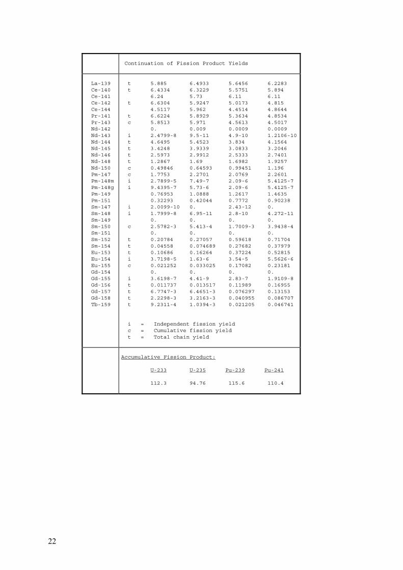
Continuation of Fission Product Yields
La-139 Ce-140 Ce-141 Ce-142 Ce-144 Pr-141 Pr-143 Nd-142 Nd-143 Nd-144 Nd-145 Nd-146 Nd-148 Nd-150 Pm-147 Pm-148m Pm-148g Pm-149 Pm-151 Sm-147 Sm-148 Sm-149 Sm-150 Sm-151 Sm-152 Sm-154 Eu-153 Eu-154 Eu-155 Gd-154 Gd-155 Gd-156 Gd-157 Gd-158 Tb-159
t 5.885 6.4933 5.6456 6.2283 t 6.4334 6.3229 5.5751 5.894 6.24 5.73 6.11 6.11 t 6.6304 5.9247 5.0173 4.815 4.5117 5.962 4.4514 4.8644 t 6.6224 5.8929 5.3634 4.8534 c 5.8513 5.971 4.5613 4.5017 0. 0.009 0.0009 0.0009 i 2.4799-8 9.5-11 4.9-10 1.2106-10 t 4.6495 5.4523 3.834 4.1564 t 3.4248 3.9339 3.0833 3.2046 t 2.5973 2.9912 2.5333 2.7401 t 1.2867 1.69 1.6982 1.9257 c 0.49846 0.64593 0.99451 1.196 c 1.7753 2.2701 2.0769 2.2601 i 2.7899-5 7.49-7 2.09-6 5.4125-7 i 9.4395-7 5.73-6 2.09-6 5.4125-7 0.76953 1.0888 1.2617 1.4635 0.32293 0.42044 0.7772 0.90238 i 2.0099-10 0. 2.43-12 0. i 1.7999-8 6.95-11 2.8-10 4.272-11 0. 0. 0. 0. c 2.5782-3 5.413-4 1.7009-3 3.9438-4 0. 0. 0. 0. t 0.20784 0.27057 0.59618 0.71704 t 0.04558 0.074689 0.27682 0.37979 t 0.10686 0.16264 0.37224 0.52815 i 3.7198-5 1.63-6 3.54-5 5.5626-6 c 0.021252 0.033025 0.17082 0.23181 0. 0. 0. 0. i 3.6198-7 4.41-9 2.83-7 1.9109-8 t 0.011737 0.013517 0.11989 0.16955 t 6.7747-3 6.4651-3 0.076297 0.13153 t 2.2298-3 3.2163-3 0.040955 0.086707 t 9.2311-4 1.0394-3 0.021205 0.046741 i = Independent fission yield c = Cumulative fission yield t = Total chain yield
Accumulative Fission Product: U-233 U-235 Pu-239 Pu-241 112.3 94.76 115.6 110.4
23
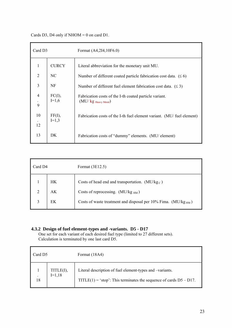
Cards D3, D4 only if NHOM = 0 on card D1.
Card D3 Format (A4,2I4,10F6.0) 1 2 3 4 . 9 10 . 12 13
CURCY NC NF FC(I), I=1,6 FF(I), I=1,3 DK
Literal abbreviation for the monetary unit MU. Number of different coated particle fabrication cost data. (≤ 6) Number of different fuel element fabrication cost data. (≤ 3) Fabrication costs of the I-th coated particle variant. (MU/ kg Heavy Metal) Fabrication costs of the I-th fuel element variant. (MU/ fuel element) Fabrication costs of “dummy” elements. (MU/ element)
Card D4 Format (3E12.5) 1 2 3
HK AK EK
Costs of head end and transportation. (MU/kg C ) Costs of reprocessing. (MU/kg HM ) Costs of waste treatment and disposal per 10% Fima. (MU/kg HM )
4.3.2 Design of fuel element-types and -variants. D5 - D17 One set for each variant of each desired fuel type (limited to 27 different sets). Calculation is terminated by one last card D5.
Card D5 Format (18A4) 1 . 18
TITLE(I), I=1,18
Literal description of fuel element-types and –variants. TITLE(1) = ‘stop’: This terminates the sequence of cards D5 – D17.
24
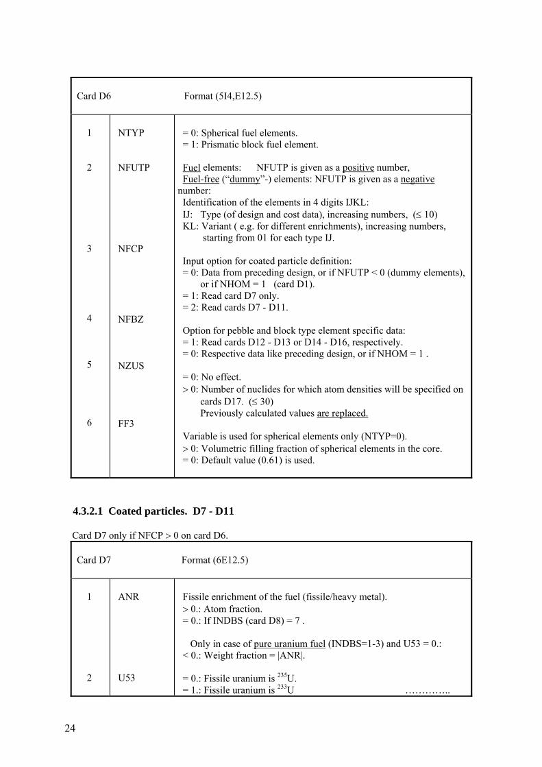
Card D6 Format (5I4,E12.5) 1 2 3 4 5 6
NTYP NFUTP NFCP NFBZ NZUS FF3
= 0: Spherical fuel elements. = 1: Prismatic block fuel element. Fuel elements: NFUTP is given as a positive number, Fuel-free (“dummy”-) elements: NFUTP is given as a negative number: Identification of the elements in 4 digits IJKL: IJ: Type (of design and cost data), increasing numbers, (≤ 10) KL: Variant ( e.g. for different enrichments), increasing numbers, starting from 01 for each type IJ. Input option for coated particle definition: = 0: Data from preceding design, or if NFUTP < 0 (dummy elements), or if NHOM = 1 (card D1). = 1: Read card D7 only. = 2: Read cards D7 - D11. Option for pebble and block type element specific data: = 1: Read cards D12 - D13 or D14 - D16, respectively. = 0: Respective data like preceding design, or if NHOM = 1 . = 0: No effect. > 0: Number of nuclides for which atom densities will be specified on cards D17. (≤ 30) Previously calculated values are replaced. Variable is used for spherical elements only (NTYP=0). > 0: Volumetric filling fraction of spherical elements in the core. = 0: Default value (0.61) is used.
4.3.2.1 Coated particles. D7 - D11 Card D7 only if NFCP > 0 on card D6.
Card D7 Format (6E12.5) 1 2
ANR U53
Fissile enrichment of the fuel (fissile/heavy metal). > 0.: Atom fraction. = 0.: If INDBS (card D8) = 7 . Only in case of pure uranium fuel (INDBS=1-3) and U53 = 0.: < 0.: Weight fraction = |ANR|. = 0.: Fissile uranium is 235U. = 1.: Fissile uranium is 233U …………..
25
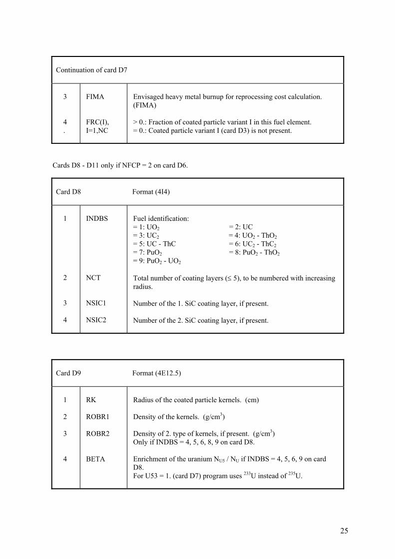
Continuation of card D7 3 4 .
FIMA FRC(I), I=1,NC
Envisaged heavy metal burnup for reprocessing cost calculation. (FIMA) > 0.: Fraction of coated particle variant I in this fuel element. = 0.: Coated particle variant I (card D3) is not present.
Cards D8 - D11 only if NFCP = 2 on card D6.
Card D8 Format (4I4) 1 2 3 4
INDBS NCT NSIC1 NSIC2
Fuel identification: = 1: UO2 = 2: UC = 3: UC2 = 4: UO2 - ThO2 = 5: UC - ThC = 6: UC2 - ThC2 = 7: PuO2 = 8: PuO2 - ThO2 = 9: PuO2 - UO2 Total number of coating layers (≤ 5), to be numbered with increasing radius. Number of the 1. SiC coating layer, if present. Number of the 2. SiC coating layer, if present.
Card D9 Format (4E12.5) 1 2 3 4
RK ROBR1 ROBR2 BETA
Radius of the coated particle kernels. (cm) Density of the kernels. (g/cm3) Density of 2. type of kernels, if present. (g/cm3) Only if INDBS = 4, 5, 6, 8, 9 on card D8. Enrichment of the uranium NU5 / NU if INDBS = 4, 5, 6, 9 on card D8. For U53 = 1. (card D7) program uses 233U instead of 235U.
26
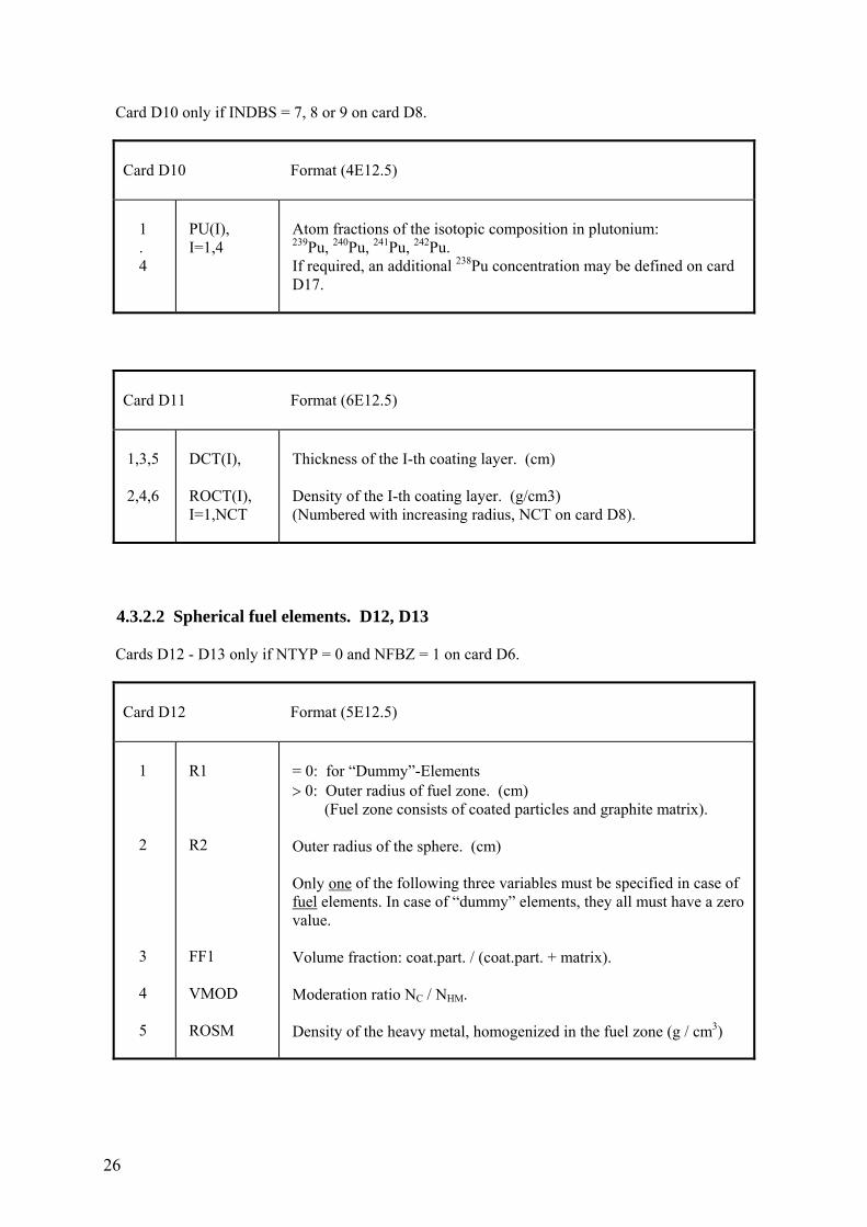
Card D10 only if INDBS = 7, 8 or 9 on card D8.
Card D10 Format (4E12.5) 1 . 4
PU(I), I=1,4
Atom fractions of the isotopic composition in plutonium: 239Pu, 240Pu, 241Pu, 242Pu. If required, an additional 238Pu concentration may be defined on card D17.
Card D11 Format (6E12.5) 1,3,5 2,4,6
DCT(I), ROCT(I), I=1,NCT
Thickness of the I-th coating layer. (cm) Density of the I-th coating layer. (g/cm3) (Numbered with increasing radius, NCT on card D8).
4.3.2.2 Spherical fuel elements. D12, D13 Cards D12 - D13 only if NTYP = 0 and NFBZ = 1 on card D6.
Card D12 Format (5E12.5) 1 2 3 4 5
R1 R2 FF1 VMOD ROSM
= 0: for “Dummy”-Elements > 0: Outer radius of fuel zone. (cm) (Fuel zone consists of coated particles and graphite matrix). Outer radius of the sphere. (cm) Only one of the following three variables must be specified in case of fuel elements. In case of “dummy” elements, they all must have a zero value. Volume fraction: coat.part. / (coat.part. + matrix). Moderation ratio NC / NHM. Density of the heavy metal, homogenized in the fuel zone (g / cm3)
27
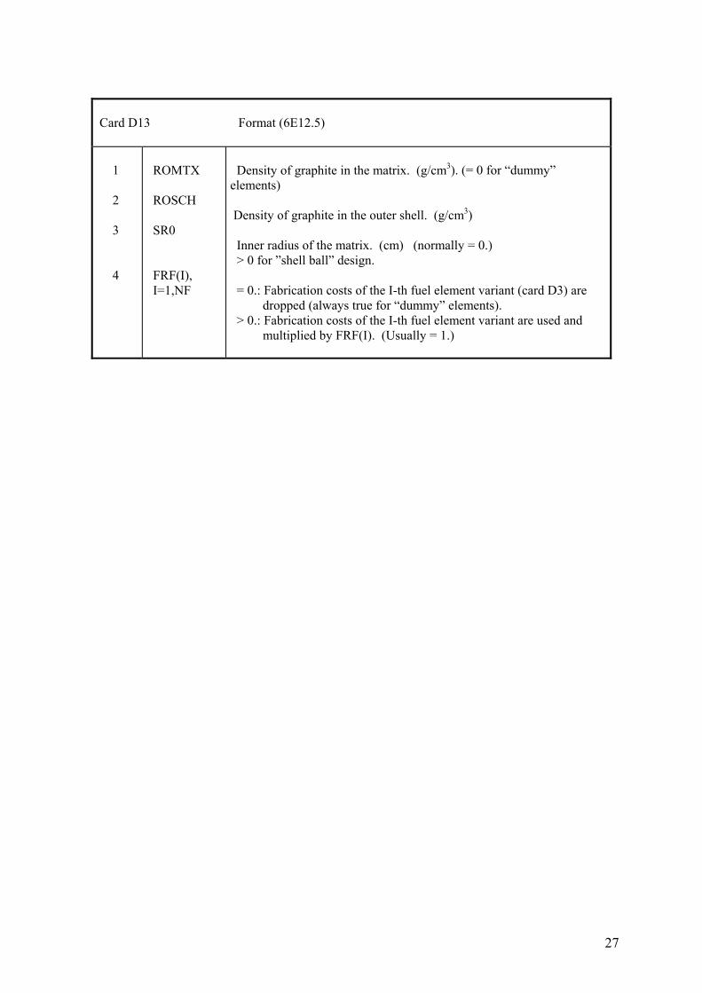
Card D13 Format (6E12.5) 1 2 3 4
ROMTX ROSCH SR0 FRF(I), I=1,NF
Density of graphite in the matrix. (g/cm3). (= 0 for “dummy” elements) Density of graphite in the outer shell. (g/cm3) Inner radius of the matrix. (cm) (normally = 0.) > 0 for ”shell ball” design. = 0.: Fabrication costs of the I-th fuel element variant (card D3) are dropped (always true for “dummy” elements). > 0.: Fabrication costs of the I-th fuel element variant are used and multiplied by FRF(I). (Usually = 1.)
28
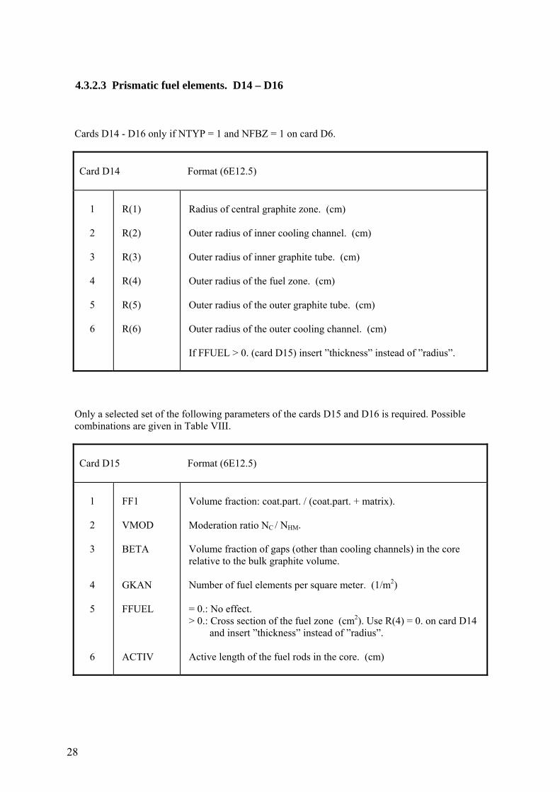
4.3.2.3 Prismatic fuel elements. D14 – D16 Cards D14 - D16 only if NTYP = 1 and NFBZ = 1 on card D6.
Card D14 Format (6E12.5) 1 2 3 4 5 6
R(1) R(2) R(3) R(4) R(5) R(6)
Radius of central graphite zone. (cm) Outer radius of inner cooling channel. (cm) Outer radius of inner graphite tube. (cm) Outer radius of the fuel zone. (cm) Outer radius of the outer graphite tube. (cm) Outer radius of the outer cooling channel. (cm) If FFUEL > 0. (card D15) insert ”thickness” instead of ”radius”.
Only a selected set of the following parameters of the cards D15 and D16 is required. Possible combinations are given in Table VIII.
Card D15 Format (6E12.5) 1 2 3 4 5 6
FF1 VMOD BETA GKAN FFUEL ACTIV
Volume fraction: coat.part. / (coat.part. + matrix). Moderation ratio NC / NHM. Volume fraction of gaps (other than cooling channels) in the core relative to the bulk graphite volume. Number of fuel elements per square meter. (1/m2) = 0.: No effect. > 0.: Cross section of the fuel zone (cm2). Use R(4) = 0. on card D14 and insert ”thickness” instead of ”radius”. Active length of the fuel rods in the core. (cm)
29
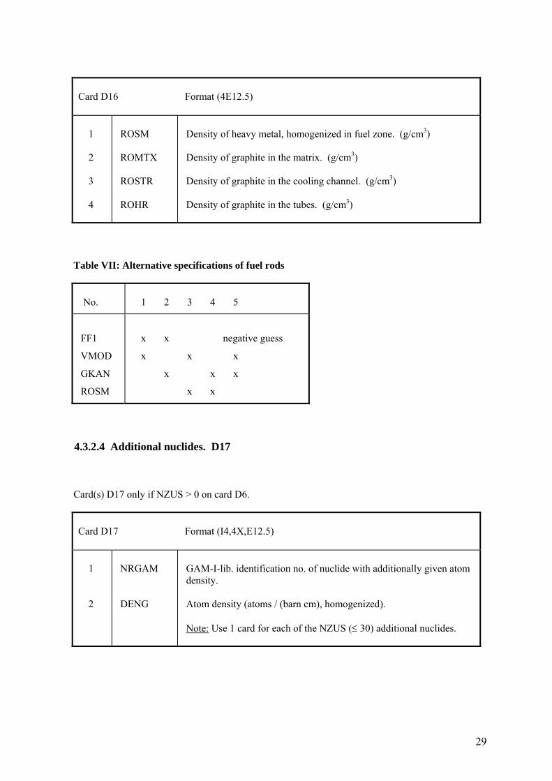
Card D16 Format (4E12.5) 1 2 3 4
ROSM ROMTX ROSTR ROHR
Density of heavy metal, homogenized in fuel zone. (g/cm3) Density of graphite in the matrix. (g/cm3) Density of graphite in the cooling channel. (g/cm3) Density of graphite in the tubes. (g/cm3)
Table VII: Alternative specifications of fuel rods
No.
1 2 3 4 5
FF1
VMOD
GKAN
ROSM
x x negative guess
x x x
x x x
x x
4.3.2.4 Additional nuclides. D17 Card(s) D17 only if NZUS > 0 on card D6.
Card D17 Format (I4,4X,E12.5) 1 2
NRGAM DENG
GAM-I-lib. identification no. of nuclide with additionally given atom density. Atom density (atoms / (barn cm), homogenized). Note: Use 1 card for each of the NZUS (≤ 30) additional nuclides.
30
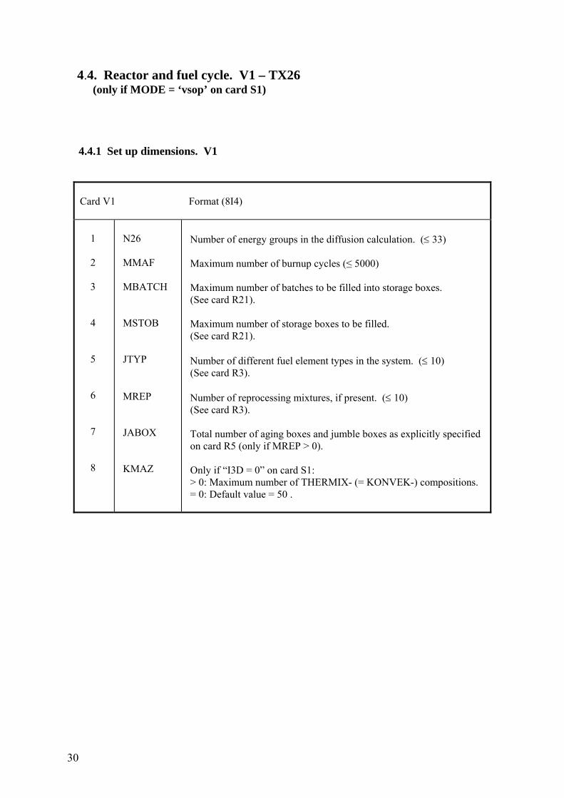
4.4. Reactor and fuel cycle. V1 – TX26 (only if MODE = ‘vsop’ on card S1) 4.4.1 Set up dimensions. V1
Card V1 Format (8I4) 1 2 3 4 5 6 7 8
N26 MMAF MBATCH MSTOB JTYP MREP JABOX KMAZ
Number of energy groups in the diffusion calculation. (≤ 33) Maximum number of burnup cycles (≤ 5000) Maximum number of batches to be filled into storage boxes. (See card R21). Maximum number of storage boxes to be filled. (See card R21). Number of different fuel element types in the system. (≤ 10) (See card R3). Number of reprocessing mixtures, if present. (≤ 10) (See card R3). Total number of aging boxes and jumble boxes as explicitly specified on card R5 (only if MREP > 0). Only if “I3D = 0” on card S1: > 0: Maximum number of THERMIX- (= KONVEK-) compositions. = 0: Default value = 50 .
31
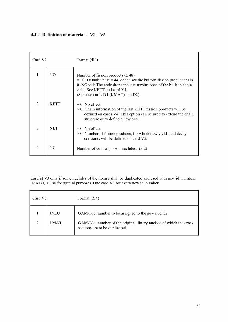
4.4.2 Definition of materials. V2 – V5
Card V2 Format (4I4) 1 2 3 4
NO KETT NLT NC
Number of fission products (≤ 48): = 0: Default value = 44, code uses the built-in fission product chain 0<NO<44: The code drops the last surplus ones of the built-in chain. > 44: See KETT and card V4. (See also cards D1 (KMAT) and D2). = 0: No effect. > 0: Chain information of the last KETT fission products will be defined on cards V4. This option can be used to extend the chain structure or to define a new one. = 0: No effect. > 0: Number of fission products, for which new yields and decay constants will be defined on card V5. Number of control poison nuclides. (≤ 2)
Card(s) V3 only if some nuclides of the library shall be duplicated and used with new id. numbers IMAT(I) > 190 for special purposes. One card V3 for every new id. number.
Card V3 Format (2I4) 1 2
JNEU LMAT
GAM-I-Id. number to be assigned to the new nuclide. GAM-I-Id. number of the original library nuclide of which the cross sections are to be duplicated.
32
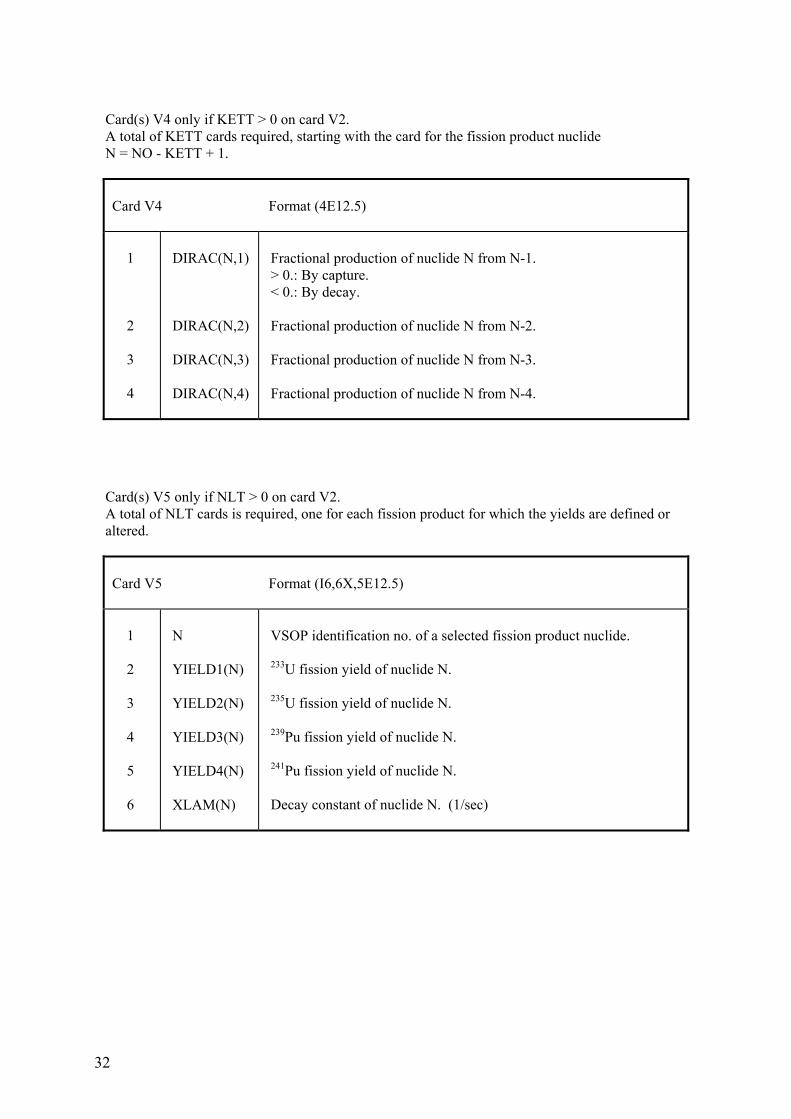
Card(s) V4 only if KETT > 0 on card V2. A total of KETT cards required, starting with the card for the fission product nuclide N = NO - KETT + 1.
Card V4 Format (4E12.5) 1 2 3 4
DIRAC(N,1) DIRAC(N,2) DIRAC(N,3) DIRAC(N,4)
Fractional production of nuclide N from N-1. > 0.: By capture. < 0.: By decay. Fractional production of nuclide N from N-2. Fractional production of nuclide N from N-3. Fractional production of nuclide N from N-4.
Card(s) V5 only if NLT > 0 on card V2. A total of NLT cards is required, one for each fission product for which the yields are defined or altered.
Card V5 Format (I6,6X,5E12.5) 1 2 3 4 5 6
N YIELD1(N) YIELD2(N) YIELD3(N) YIELD4(N) XLAM(N)
VSOP identification no. of a selected fission product nuclide. 233U fission yield of nuclide N. 235U fission yield of nuclide N. 239Pu fission yield of nuclide N. 241Pu fission yield of nuclide N. Decay constant of nuclide N. (1/sec)
33
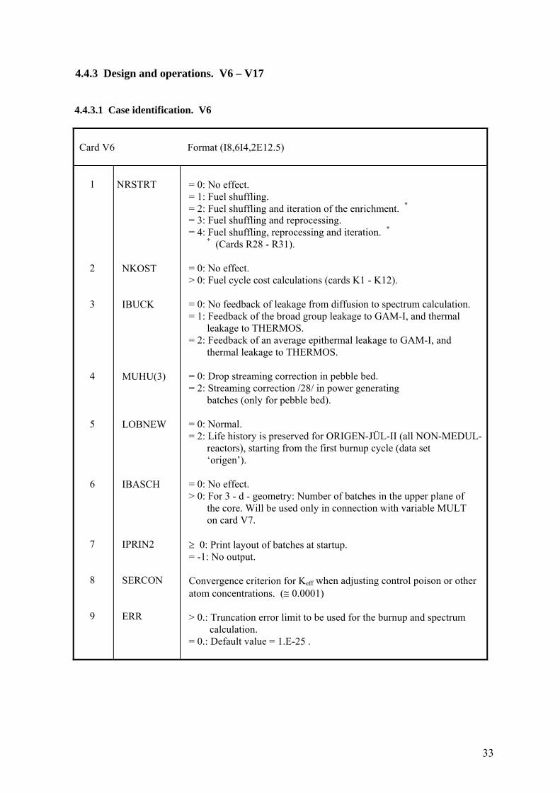
4.4.3 Design and operations. V6 – V17 4.4.3.1 Case identification. V6
Card V6 Format (I8,6I4,2E12.5) 1 2 3 4 5 6 7 8 9
NRSTRT NKOST IBUCK MUHU(3) LOBNEW IBASCH IPRIN2 SERCON ERR
= 0: No effect. = 1: Fuel shuffling. = 2: Fuel shuffling and iteration of the enrichment. * = 3: Fuel shuffling and reprocessing. = 4: Fuel shuffling, reprocessing and iteration. * * (Cards R28 - R31). = 0: No effect. > 0: Fuel cycle cost calculations (cards K1 - K12). = 0: No feedback of leakage from diffusion to spectrum calculation. = 1: Feedback of the broad group leakage to GAM-I, and thermal leakage to THERMOS. = 2: Feedback of an average epithermal leakage to GAM-I, and thermal leakage to THERMOS. = 0: Drop streaming correction in pebble bed. = 2: Streaming correction /28/ in power generating batches (only for pebble bed). = 0: Normal. = 2: Life history is preserved for ORIGEN-JÜL-II (all NON-MEDUL- reactors), starting from the first burnup cycle (data set ‘origen’). = 0: No effect. > 0: For 3 - d - geometry: Number of batches in the upper plane of the core. Will be used only in connection with variable MULT on card V7. ≥ 0: Print layout of batches at startup. = -1: No output. Convergence criterion for Keff when adjusting control poison or other atom concentrations. (≅ 0.0001) > 0.: Truncation error limit to be used for the burnup and spectrum calculation. = 0.: Default value = 1.E-25 .
34
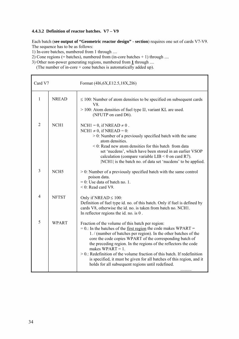
4.4.3.2 Definition of reactor batches. V7 – V9 Each batch (see output of “Geometric reactor design” - section) requires one set of cards V7-V9. The sequence has to be as follows: 1) In-core batches, numbered from 1 through .... 2) Cone regions (= batches), numbered from (in-core batches + 1) through .... 3) Other non-power generating regions, numbered from 1 through .... (The number of in-core + cone batches is automatically added up).
Card V7 Format (4I6,6X,E12.5,18X,2I6) 1 2 3 4 5
NREAD NCH1 NCH5 NFTST WPART
≤ 100: Number of atom densities to be specified on subsequent cards V8. > 100: Atom densities of fuel type IJ, variant KL are used. (NFUTP on card D6). NCH1 = 0, if NREAD ≠ 0 . NCH1 ≠ 0, if NREAD = 0: > 0: Number of a previously specified batch with the same atom densities. < 0: Read new atom densities for this batch from data set ‘nucdens’, which have been stored in an earlier VSOP calculation (compare variable LIB < 0 on card R7). |NCH1| is the batch no. of data set ‘nucdens’ to be applied. > 0: Number of a previously specified batch with the same control poison data. = 0: Use data of batch no. 1. < 0: Read card V9. Only if NREAD ≤ 100: Definition of fuel type id. no. of this batch. Only if fuel is defined by cards V8, otherwise the id. no. is taken from batch no. NCH1. In reflector regions the id. no. is 0 . Fraction of the volume of this batch per region: = 0.: In the batches of the first region the code makes WPART = 1. / (number of batches per region). In the other batches of the core the code copies WPART of the corresponding batch of the preceding region. In the regions of the reflectors the code makes WPART = 1. > 0.: Redefinition of the volume fraction of this batch. If redefinition is specified, it must be given for all batches of this region, and it holds for all subsequent regions until redefined. ..........
35
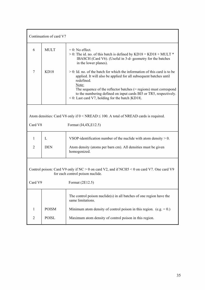
Continuation of card V7 6 7
MULT KD18
= 0: No effect. > 0: The id. no. of this batch is defined by KD18 = KD18 + MULT * IBASCH (Card V6). (Useful in 3-d- geometry for the batches in the lower planes). > 0: Id. no. of the batch for which the information of this card is to be applied. It will also be applied for all subsequent batches until redefined. Note: The sequence of the reflector batches (= regions) must correspond to the numbering defined on input cards BI5 or TR5, respectively. < 0: Last card V7, holding for the batch |KD18|.
Atom densities: Card V8 only if 0 < NREAD ≤ 100. A total of NREAD cards is required. Card V8 Format (I4,4X,E12.5) 1 2
L DEN
VSOP-identification number of the nuclide with atom density > 0. Atom density (atoms per barn cm). All densities must be given homogenized.
Control poison: Card V9 only if NC > 0 on card V2, and if NCH5 < 0 on card V7. One card V9 for each control poison nuclide. Card V9 Format (2E12.5) 1 2
POISM POISL
The control poison nuclide(s) in all batches of one region have the same limitations. Minimum atom density of control poison in this region. (e.g. = 0.) Maximum atom density of control poison in this region.
36
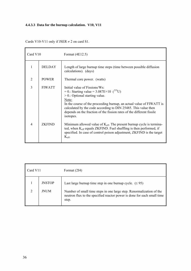
4.4.3.3 Data for the burnup calculation. V10, V11 Cards V10-V11 only if JSER ≠ 2 on card S1.
Card V10 Format (4E12.5) 1 2 3 4
DELDAY POWER FIWATT ZKFIND
Length of large burnup time steps (time between possible diffusion calculations). (days) Thermal core power. (watts) Initial value of Fissions/Ws: = 0.: Starting value = 3.087E+10 (235U) > 0.: Optional starting value. Note: In the course of the proceeding burnup, an actual value of FIWATT is calculated by the code according to DIN 25485. This value then depends on the fraction of the fission rates of the different fissile isotopes. Minimum allowed value of Keff. The present burnup cycle is termina- ted, when Keff equals ZKFIND. Fuel shuffling is then performed, if specified. In case of control poison adjustment, ZKFIND is the target Keff.
Card V11 Format (2I4) 1 2
JNSTOP JNUM
Last large burnup time step in one burnup cycle. (≤ 95) Number of small time steps in one large step. Renormalization of the neutron flux to the specified reactor power is done for each small time step.
37
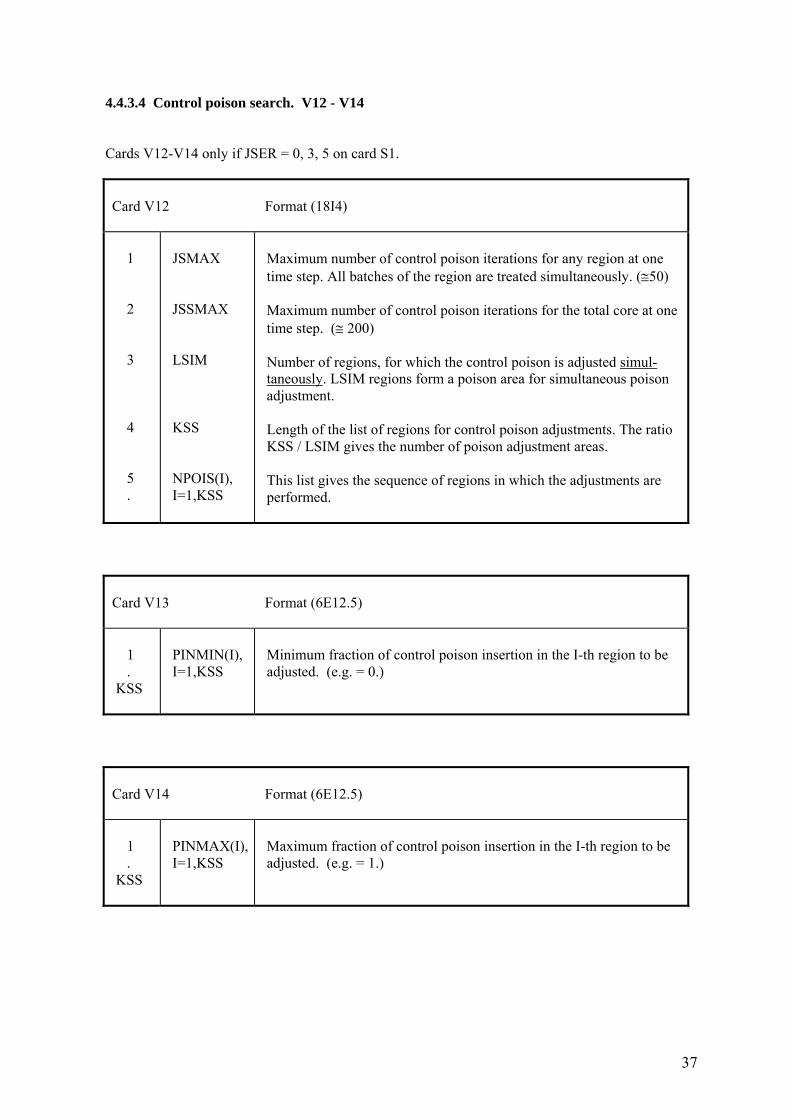
4.4.3.4 Control poison search. V12 - V14 Cards V12-V14 only if JSER = 0, 3, 5 on card S1.
Card V12 Format (18I4) 1 2 3 4 5 .
JSMAX JSSMAX LSIM KSS NPOIS(I), I=1,KSS
Maximum number of control poison iterations for any region at one time step. All batches of the region are treated simultaneously. (≅50) Maximum number of control poison iterations for the total core at one time step. (≅ 200) Number of regions, for which the control poison is adjusted simul- taneously. LSIM regions form a poison area for simultaneous poison adjustment. Length of the list of regions for control poison adjustments. The ratio KSS / LSIM gives the number of poison adjustment areas. This list gives the sequence of regions in which the adjustments are performed.
Card V13 Format (6E12.5) 1 . KSS
PINMIN(I), I=1,KSS
Minimum fraction of control poison insertion in the I-th region to be adjusted. (e.g. = 0.)
Card V14 Format (6E12.5) 1 . KSS
PINMAX(I), I=1,KSS
Maximum fraction of control poison insertion in the I-th region to be adjusted. (e.g. = 1.)
38
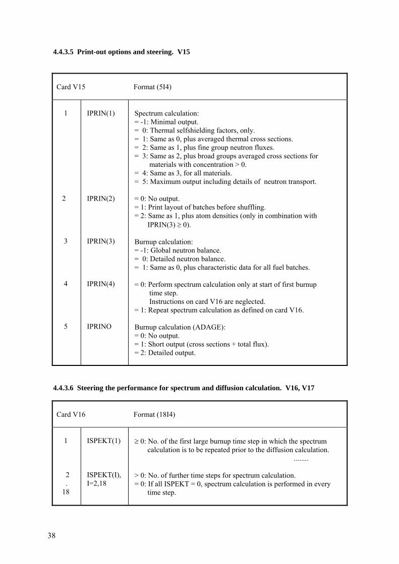
4.4.3.5 Print-out options and steering. V15
Card V15 Format (5I4) 1 2 3 4 5
IPRIN(1) IPRIN(2) IPRIN(3) IPRIN(4) IPRINO
Spectrum calculation: = -1: Minimal output. = 0: Thermal selfshielding factors, only. = 1: Same as 0, plus averaged thermal cross sections. = 2: Same as 1, plus fine group neutron fluxes. = 3: Same as 2, plus broad groups averaged cross sections for materials with concentration > 0. = 4: Same as 3, for all materials. = 5: Maximum output including details of neutron transport. = 0: No output. = 1: Print layout of batches before shuffling. = 2: Same as 1, plus atom densities (only in combination with IPRIN(3) ≥ 0). Burnup calculation: = -1: Global neutron balance. = 0: Detailed neutron balance. = 1: Same as 0, plus characteristic data for all fuel batches. = 0: Perform spectrum calculation only at start of first burnup time step. Instructions on card V16 are neglected. = 1: Repeat spectrum calculation as defined on card V16. Burnup calculation (ADAGE): = 0: No output. = 1: Short output (cross sections + total flux). = 2: Detailed output.
4.4.3.6 Steering the performance for spectrum and diffusion calculation. V16, V17
Card V16 Format (18I4) 1 2 . 18
ISPEKT(1) ISPEKT(I), I=2,18
≥ 0: No. of the first large burnup time step in which the spectrum calculation is to be repeated prior to the diffusion calculation. ........ > 0: No. of further time steps for spectrum calculation. = 0: If all ISPEKT = 0, spectrum calculation is performed in every time step.
39
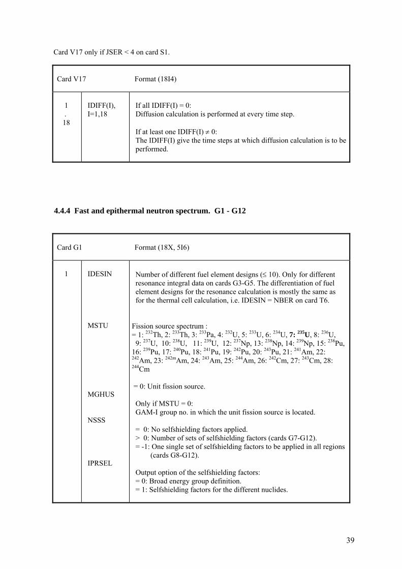
Card V17 only if JSER < 4 on card S1.
Card V17 Format (18I4) 1 . 18
IDIFF(I), I=1,18
If all IDIFF(I) = 0: Diffusion calculation is performed at every time step. If at least one IDIFF(I) ≠ 0: The IDIFF(I) give the time steps at which diffusion calculation is to be performed.
4.4.4 Fast and epithermal neutron spectrum. G1 - G12
Card G1 Format (18X, 5I6) 1
IDESIN MSTU MGHUS NSSS IPRSEL
Number of different fuel element designs (≤ 10). Only for different resonance integral data on cards G3-G5. The differentiation of fuel element designs for the resonance calculation is mostly the same as for the thermal cell calculation, i.e. IDESIN = NBER on card T6. Fission source spectrum : = 1: 232Th, 2: 233Th, 3: 233Pa, 4: 232U, 5: 233U, 6: 234U, 7: 235U, 8: 236U, 9: 237U, 10: 238U, 11: 239U, 12: 237Np, 13: 238Np, 14: 239Np, 15: 238Pu, 16: 239Pu, 17: 240Pu, 18: 241Pu, 19: 242Pu, 20: 243Pu, 21: 241Am, 22: 242Am, 23: 242mAm, 24: 243Am, 25: 244Am, 26: 242Cm, 27: 243Cm, 28: 244Cm = 0: Unit fission source. Only if MSTU = 0: GAM-I group no. in which the unit fission source is located. = 0: No selfshielding factors applied. > 0: Number of sets of selfshielding factors (cards G7-G12). = -1: One single set of selfshielding factors to be applied in all regions (cards G8-G12). Output option of the selfshielding factors: = 0: Broad energy group definition. = 1: Selfshielding factors for the different nuclides.
40
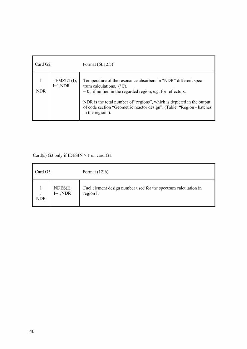
Card G2 Format (6E12.5) 1 . NDR
TEMZUT(I), I=1,NDR
Temperature of the resonance absorbers in “NDR” different spec- trum calculations. (°C). = 0., if no fuel in the regarded region, e.g. for reflectors. NDR is the total number of “regions”, which is depicted in the output of code section “Geometric reactor design”. (Table: “Region - batches in the region”).
Card(s) G3 only if IDESIN > 1 on card G1.
Card G3 Format (12I6) 1 . NDR
NDES(I), I=1,NDR
Fuel element design number used for the spectrum calculation in region I.
41
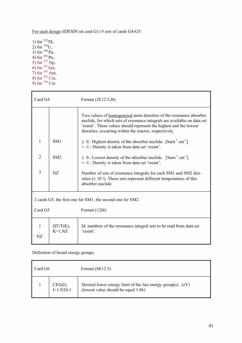
For each design (IDESIN on card G1) 9 sets of cards G4-G5: 1) for 232Th, 2) for 238U, 3) for 240 Pu, 4) for 242 Pu, 5) for 237 Np, 6) for 241Am, 7) for 243 Am, 8) for 242 Cm, 9) for 244 Cm
Card G4 Format (2E12.5,I6) 1 2 3
SM1 SM2 NZ
Two values of homogenized atom densities of the resonance absorber nuclide, for which sets of resonance integrals are available on data set ‘resint’. These values should represent the highest and the lowest densities, occurring within the reactor, respectively. ≥ 0.: Highest density of the absorber nuclide. [barn-1 cm-1] = -1.: Density is taken from data set ‘resint’. ≥ 0.: Lowest density of the absorber nuclide. [barn-1 cm-1] = -1.: Density is taken from data set ‘resint’. Number of sets of resonance integrals for each SM1 and SM2 den- sities (≤ 10 !). These sets represent different temperatures of this absorber nuclide.
2 cards G5, the first one for SM1, the second one for SM2. Card G5 Format (12I6) 1 . NZ
IZUT(K), K=1,NZ
Id. numbers of the resonance integral sets to be read from data set ‘resint’.
Definition of broad energy groups.
Card G6 Format (6E12.5) 1 .
CEG(I), I=1,N26-1
Desired lower energy limit of the fast energy group(s). (eV) (lowest value should be equal 1.86)
42
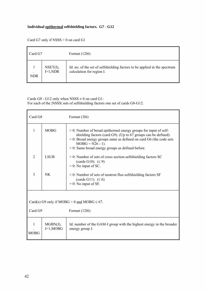
Individual epithermal selfshielding factors. G7 - G12 Card G7 only if NSSS > 0 on card G1
Card G7 Format (12I6) 1 . NDR
NSET(I), I=1,NDR
Id. no. of the set of selfshielding factors to be applied in the spectrum calculation for region I.
Cards G8 - G12 only when NSSS ≠ 0 on card G1: For each of the |NSSS| sets of selfshielding factors one set of cards G8-G12.
Card G8 Format (3I6) 1 2 3
MOBG LSUB NK
> 0: Number of broad epithermal energy groups for input of self- shielding factors (card G9). (Up to 67 groups can be defined). = 0: Broad energy groups same as defined on card G6 (the code sets MOBG = N26 - 1). < 0: Same broad energy groups as defined before. > 0: Number of sets of cross section-selfshielding factors SC (cards G10). (≤ 9) = 0: No input of SC. > 0: Number of sets of neutron flux-selfshielding factors SF (cards G11). (≤ 6) = 0: No input of SF.
Card(s) G9 only if MOBG > 0 and MOBG ≤ 67. Card G9 Format (12I6) 1 . MOBG
MGBN(J), J=1,MOBG
Id. number of the GAM-I group with the highest energy in the broader energy group J.
43
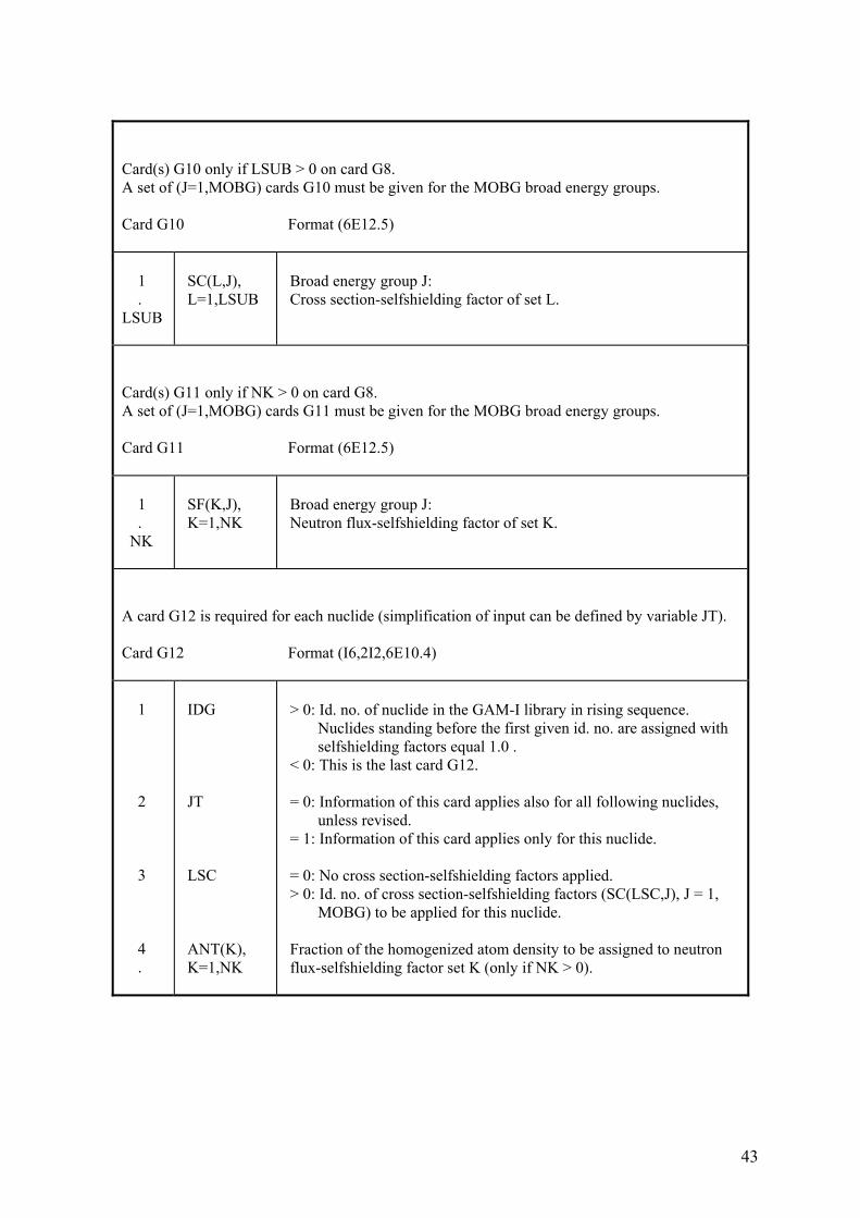
Card(s) G10 only if LSUB > 0 on card G8. A set of (J=1,MOBG) cards G10 must be given for the MOBG broad energy groups. Card G10 Format (6E12.5) 1 . LSUB
SC(L,J), L=1,LSUB
Broad energy group J: Cross section-selfshielding factor of set L.
Card(s) G11 only if NK > 0 on card G8. A set of (J=1,MOBG) cards G11 must be given for the MOBG broad energy groups. Card G11 Format (6E12.5) 1 . NK
SF(K,J), K=1,NK
Broad energy group J: Neutron flux-selfshielding factor of set K.
A card G12 is required for each nuclide (simplification of input can be defined by variable JT). Card G12 Format (I6,2I2,6E10.4) 1 2 3 4 .
IDG JT LSC ANT(K), K=1,NK
> 0: Id. no. of nuclide in the GAM-I library in rising sequence. Nuclides standing before the first given id. no. are assigned with selfshielding factors equal 1.0 . < 0: This is the last card G12. = 0: Information of this card applies also for all following nuclides, unless revised. = 1: Information of this card applies only for this nuclide. = 0: No cross section-selfshielding factors applied. > 0: Id. no. of cross section-selfshielding factors (SC(LSC,J), J = 1, MOBG) to be applied for this nuclide. Fraction of the homogenized atom density to be assigned to neutron flux-selfshielding factor set K (only if NK > 0).
44
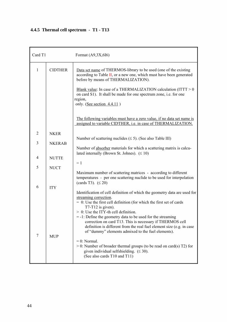
4.4.5 Thermal cell spectrum - T1 - T13
Card T1 Format (A9,3X,6I6) 1 2 3 4 5 6 7
CIDTHER NKER NKERAB NUTTE NUCT ITY MUP
Data set name of THERMOS-library to be used (one of the existing according to Table II, or a new one, which must have been generated before by means of THERMALIZATION). Blank value: In case of a THERMALIZATION calculation (ITTT > 0 on card S1). It shall be made for one spectrum zone, i.e. for one region, only. (See section 4.4.11 ) The following variables must have a zero value, if no data set name is assigned to variable CIDTHER, i.e. in case of THERMALIZATION. Number of scattering nuclides (≤ 5). (See also Table III) Number of absorber materials for which a scattering matrix is calcu- lated internally (Brown St. Johnes). (≤ 10) = 1 Maximum number of scattering matrices - according to different temperatures - per one scattering nuclide to be used for interpolation (cards T3). (≤ 20) Identification of cell definition of which the geometry data are used for streaming correction. = 0: Use the first cell definition (for which the first set of cards T7-T12 is given). > 0: Use the ITY-th cell definition. = -1: Define the geometry data to be used for the streaming correction on card T13. This is necessary if THERMOS cell definition is different from the real fuel element size (e.g. in case of “dummy” elements admixed to the fuel elements). = 0: Normal. > 0: Number of broader thermal groups (to be read on card(s) T2) for given individual selfshielding. (≤ 30). (See also cards T10 and T11)
45
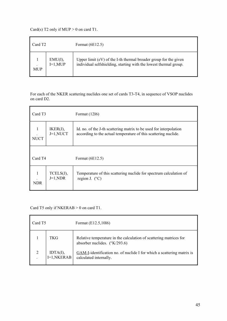
Card(s) T2 only if MUP > 0 on card T1.
Card T2 Format (6E12.5) 1 . MUP
EMU(I), I=1,MUP
Upper limit (eV) of the I-th thermal broader group for the given individual selfshielding, starting with the lowest thermal group.
For each of the NKER scattering nuclides one set of cards T3-T4, in sequence of VSOP nuclides on card D2.
Card T3 Format (12I6) 1 . NUCT
IKER(J), J=1,NUCT
Id. no. of the J-th scattering matrix to be used for interpolation according to the actual temperature of this scattering nuclide.
Card T4 Format (6E12.5) 1 . NDR
TCELS(J), J=1,NDR
Temperature of this scattering nuclide for spectrum calculation of region J. (°C)
Card T5 only if NKERAB > 0 on card T1.
Card T5 Format (E12.5,10I6) 1 2 .
TKG IDTA(I), I=1,NKERAB
Relative temperature in the calculation of scattering matrices for absorber nuclides. (°K/293.6) GAM-I-identification no. of nuclide I for which a scattering matrix is calculated internally.
46
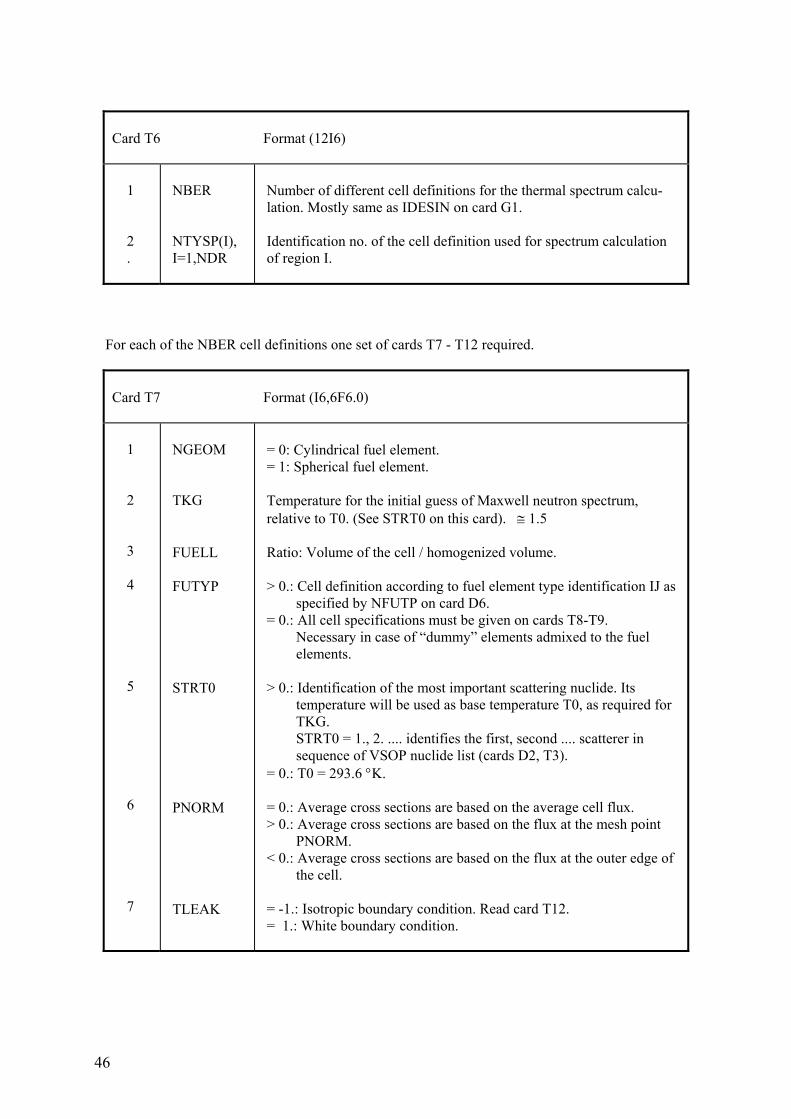
Card T6 Format (12I6) 1 2 .
NBER NTYSP(I), I=1,NDR
Number of different cell definitions for the thermal spectrum calcu- lation. Mostly same as IDESIN on card G1. Identification no. of the cell definition used for spectrum calculation of region I.
For each of the NBER cell definitions one set of cards T7 - T12 required.
Card T7 Format (I6,6F6.0) 1 2 3 4 5 6 7
NGEOM TKG FUELL FUTYP STRT0 PNORM TLEAK
= 0: Cylindrical fuel element. = 1: Spherical fuel element. Temperature for the initial guess of Maxwell neutron spectrum, relative to T0. (See STRT0 on this card). ≅ 1.5 Ratio: Volume of the cell / homogenized volume. > 0.: Cell definition according to fuel element type identification IJ as specified by NFUTP on card D6. = 0.: All cell specifications must be given on cards T8-T9. Necessary in case of “dummy” elements admixed to the fuel elements. > 0.: Identification of the most important scattering nuclide. Its temperature will be used as base temperature T0, as required for TKG. STRT0 = 1., 2. .... identifies the first, second .... scatterer in sequence of VSOP nuclide list (cards D2, T3). = 0.: T0 = 293.6 °K. = 0.: Average cross sections are based on the average cell flux. > 0.: Average cross sections are based on the flux at the mesh point PNORM. < 0.: Average cross sections are based on the flux at the outer edge of the cell. = -1.: Isotropic boundary condition. Read card T12. = 1.: White boundary condition.
47
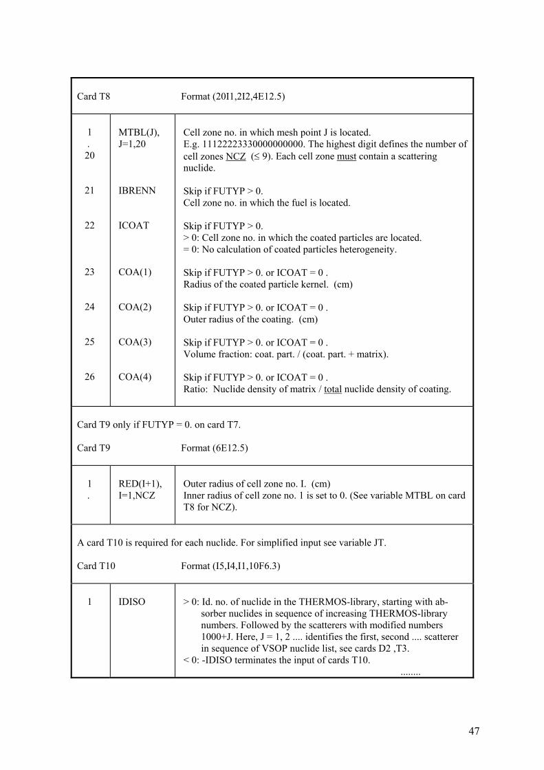
Card T8 Format (20I1,2I2,4E12.5) 1 . 20 21 22 23 24 25 26
MTBL(J), J=1,20 IBRENN ICOAT COA(1) COA(2) COA(3) COA(4)
Cell zone no. in which mesh point J is located. E.g. 11122223330000000000. The highest digit defines the number of cell zones NCZ (≤ 9). Each cell zone must contain a scattering nuclide. Skip if FUTYP > 0. Cell zone no. in which the fuel is located. Skip if FUTYP > 0. > 0: Cell zone no. in which the coated particles are located. = 0: No calculation of coated particles heterogeneity. Skip if FUTYP > 0. or ICOAT = 0 . Radius of the coated particle kernel. (cm) Skip if FUTYP > 0. or ICOAT = 0 . Outer radius of the coating. (cm) Skip if FUTYP > 0. or ICOAT = 0 . Volume fraction: coat. part. / (coat. part. + matrix). Skip if FUTYP > 0. or ICOAT = 0 . Ratio: Nuclide density of matrix / total nuclide density of coating.
Card T9 only if FUTYP = 0. on card T7. Card T9 Format (6E12.5) 1 .
RED(I+1), I=1,NCZ
Outer radius of cell zone no. I. (cm) Inner radius of cell zone no. 1 is set to 0. (See variable MTBL on card T8 for NCZ).
A card T10 is required for each nuclide. For simplified input see variable JT. Card T10 Format (I5,I4,I1,10F6.3) 1
IDISO
> 0: Id. no. of nuclide in the THERMOS-library, starting with ab- sorber nuclides in sequence of increasing THERMOS-library numbers. Followed by the scatterers with modified numbers 1000+J. Here, J = 1, 2 .... identifies the first, second .... scatterer in sequence of VSOP nuclide list, see cards D2 ,T3. < 0: -IDISO terminates the input of cards T10. ........
48
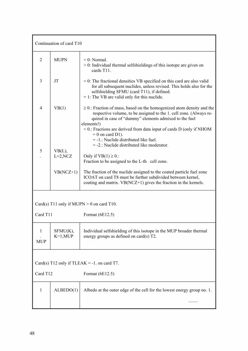
Continuation of card T10 2 3 4 5 .
MUPN JT VB(1) VB(L), L=2,NCZ VB(NCZ+1)
= 0: Normal. > 0: Individual thermal selfshieldings of this isotope are given on cards T11. = 0: The fractional densities VB specified on this card are also valid for all subsequent nuclides, unless revised. This holds also for the selfshielding SFMU (card T11), if defined. = 1: The VB are valid only for this nuclide. ≥ 0.: Fraction of mass, based on the homogenized atom density and the respective volume, to be assigned to the 1. cell zone. (Always re- quired in case of “dummy” elements admixed to the fuel elements!) < 0.: Fractions are derived from data input of cards D (only if NHOM = 0 on card D1). = -1.: Nuclide distributed like fuel. = -2.: Nuclide distributed like moderator. Only if VB(1) ≥ 0.: Fraction to be assigned to the L-th cell zone. The fraction of the nuclide assigned to the coated particle fuel zone ICOAT on card T8 must be further subdivided between kernel, coating and matrix. VB(NCZ+1) gives the fraction in the kernels.
Card(s) T11 only if MUPN > 0 on card T10. Card T11 Format (6E12.5) 1 . MUP
SFMU(K), K=1,MUP
Individual selfshielding of this isotope in the MUP broader thermal energy groups as defined on card(s) T2.
Card(s) T12 only if TLEAK = -1. on card T7. Card T12 Format (6E12.5) 1
ALBEDO(1)
Albedo at the outer edge of the cell for the lowest energy group no. 1. ........
49
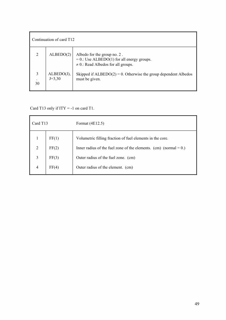
Continuation of card T12 2 3 . 30
ALBEDO(2) ALBEDO(J), J=3,30
Albedo for the group no. 2 . = 0.: Use ALBEDO(1) for all energy groups. ≠ 0.: Read Albedos for all groups. Skipped if ALBEDO(2) = 0. Otherwise the group dependent Albedos must be given.
Card T13 only if ITY = -1 on card T1.
Card T13 Format (4E12.5) 1 2 3 4
FF(1) FF(2) FF(3) FF(4)
Volumetric filling fraction of fuel elements in the core. Inner radius of the fuel zone of the elements. (cm) (normal = 0.) Outer radius of the fuel zone. (cm) Outer radius of the element. (cm)
50
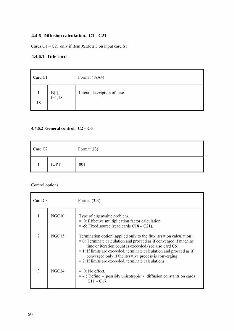
4.4.6 Diffusion calculation. C1 - C21 Cards C1 – C21 only if item JSER ≤ 3 on input card S1 ! 4.4.6.1 Title card
Card C1 Format (18A4) 1 . 18
B(I), I=1,18
Literal description of case.
4.4.6.2 General control. C2 – C6
Card C2 Format (I3) 1
IOPT
001
Control options.
Card C3 Format (3I3) 1 2 3
NGC10 NGC15 NGC24
Type of eigenvalue problem. = 0: Effective multiplication factor calculation. = -5: Fixed source (read cards C18 – C21). Termination option (applied only to the flux iteration calculation). = 0: Terminate calculation and proceed as if converged if machine time or iteration count is exceeded (see also card C5). = 1: If limits are exceeded, terminate calculation and proceed as if converged only if the iterative process is converging. = 2: If limits are exceeded, terminate calculations. = 0: No effect. = -1: Define - possibly unisotropic - diffusion constants on cards C11 – C17.
51
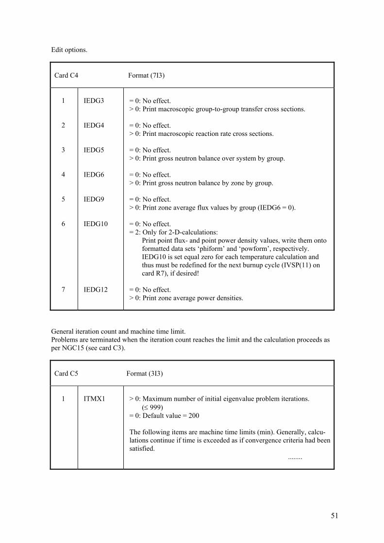
Edit options.
Card C4 Format (7I3) 1 2 3 4 5 6 7
IEDG3 IEDG4 IEDG5 IEDG6 IEDG9 IEDG10 IEDG12
= 0: No effect. > 0: Print macroscopic group-to-group transfer cross sections. = 0: No effect. > 0: Print macroscopic reaction rate cross sections. = 0: No effect. > 0: Print gross neutron balance over system by group. = 0: No effect. > 0: Print gross neutron balance by zone by group. = 0: No effect. > 0: Print zone average flux values by group (IEDG6 = 0). = 0: No effect. = 2: Only for 2-D-calculations: Print point flux- and point power density values, write them onto formatted data sets ‘phiform’ and ‘powform’, respectively. IEDG10 is set equal zero for each temperature calculation and thus must be redefined for the next burnup cycle (IVSP(11) on card R7), if desired! = 0: No effect. > 0: Print zone average power densities.
General iteration count and machine time limit. Problems are terminated when the iteration count reaches the limit and the calculation proceeds as per NGC15 (see card C3).
Card C5 Format (3I3) 1
ITMX1
> 0: Maximum number of initial eigenvalue problem iterations. (≤ 999) = 0: Default value = 200 The following items are machine time limits (min). Generally, calcu- lations continue if time is exceeded as if convergence criteria had been satisfied. ........
52
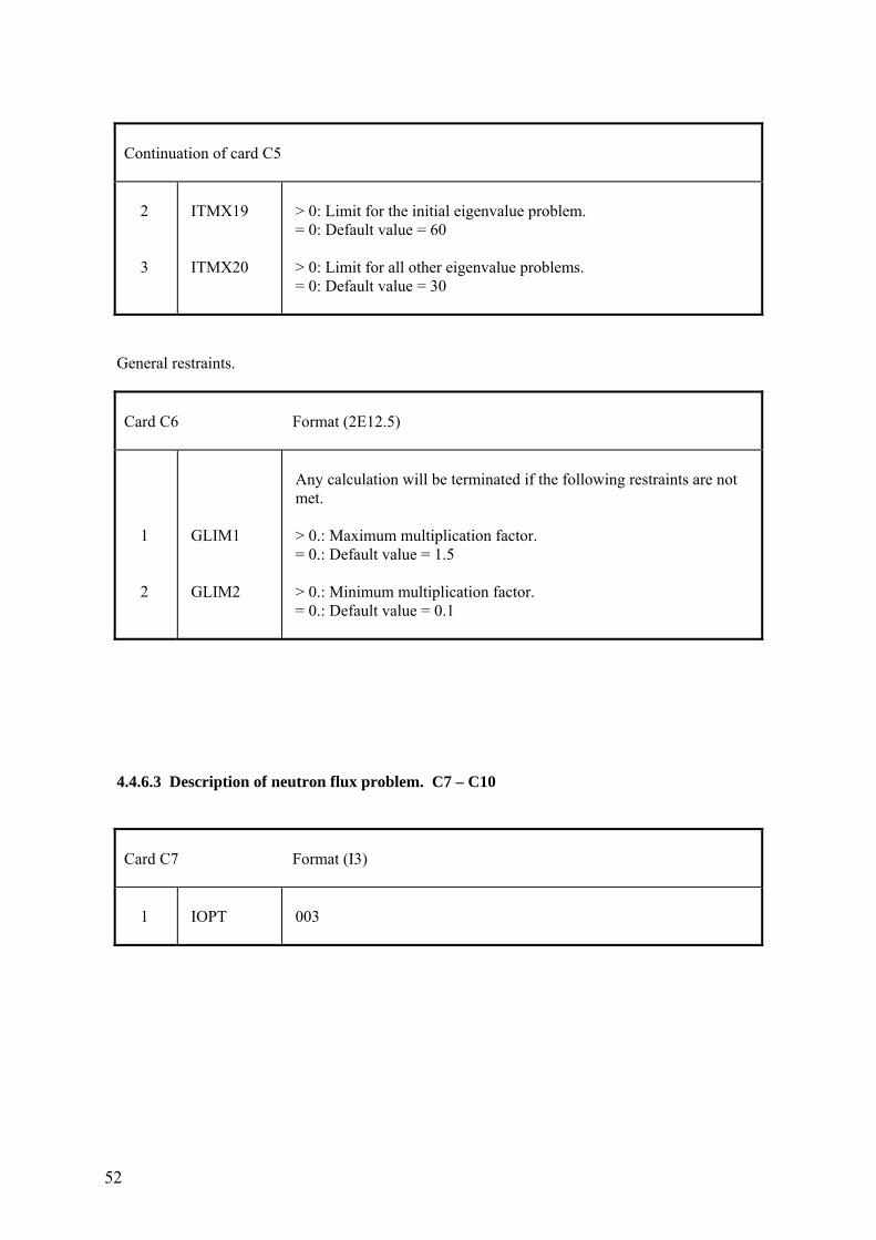
Continuation of card C5 2 3
ITMX19 ITMX20
> 0: Limit for the initial eigenvalue problem. = 0: Default value = 60 > 0: Limit for all other eigenvalue problems. = 0: Default value = 30
General restraints.
Card C6 Format (2E12.5) 1 2
GLIM1 GLIM2
Any calculation will be terminated if the following restraints are not met. > 0.: Maximum multiplication factor. = 0.: Default value = 1.5 > 0.: Minimum multiplication factor. = 0.: Default value = 0.1
4.4.6.3 Description of neutron flux problem. C7 – C10
Card C7 Format (I3) 1
IOPT
003
53
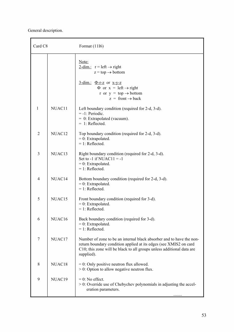
General description.
Card C8 Format (11I6) 1 2 3 4 5 6 7 8 9
NUAC11 NUAC12 NUAC13 NUAC14 NUAC15 NUAC16 NUAC17 NUAC18 NUAC19
Note: 2-dim.: r = left → right z = top → bottom 3-dim.: Φ-r-z or x-y-z Φ or x = left → right r or y = top → bottom z = front → back Left boundary condition (required for 2-d, 3-d). = -1: Periodic. = 0: Extrapolated (vacuum). = 1: Reflected. Top boundary condition (required for 2-d, 3-d). = 0: Extrapolated. = 1: Reflected. Right boundary condition (required for 2-d, 3-d). Set to -1 if NUAC11 = -1 = 0: Extrapolated. = 1: Reflected. Bottom boundary condition (required for 2-d, 3-d). = 0: Extrapolated. = 1: Reflected. Front boundary condition (required for 3-d). = 0: Extrapolated. = 1: Reflected. Back boundary condition (required for 3-d). = 0: Extrapolated. = 1: Reflected. Number of zone to be an internal black absorber and to have the non- return boundary condition applied at its edges (see XMIS2 on card C10; this zone will be black to all groups unless additional data are supplied). = 0: Only positive neutron flux allowed. > 0: Option to allow negative neutron flux. = 0: No effect. > 0: Override use of Chebychev polynomials in adjusting the accel- eration parameters. ........
54
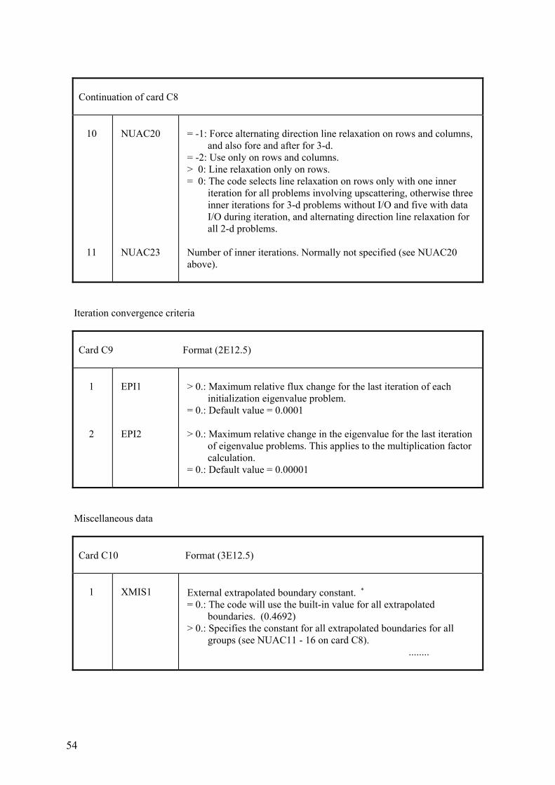
Continuation of card C8 10 11
NUAC20 NUAC23
= -1: Force alternating direction line relaxation on rows and columns, and also fore and after for 3-d. = -2: Use only on rows and columns. > 0: Line relaxation only on rows. = 0: The code selects line relaxation on rows only with one inner iteration for all problems involving upscattering, otherwise three inner iterations for 3-d problems without I/O and five with data I/O during iteration, and alternating direction line relaxation for all 2-d problems. Number of inner iterations. Normally not specified (see NUAC20 above).
Iteration convergence criteria
Card C9 Format (2E12.5) 1 2
EPI1 EPI2
> 0.: Maximum relative flux change for the last iteration of each initialization eigenvalue problem. = 0.: Default value = 0.0001 > 0.: Maximum relative change in the eigenvalue for the last iteration of eigenvalue problems. This applies to the multiplication factor calculation. = 0.: Default value = 0.00001
Miscellaneous data
Card C10 Format (3E12.5) 1
XMIS1
External extrapolated boundary constant. ∗ = 0.: The code will use the built-in value for all extrapolated boundaries. (0.4692) > 0.: Specifies the constant for all extrapolated boundaries for all groups (see NUAC11 - 16 on card C8). ........
55
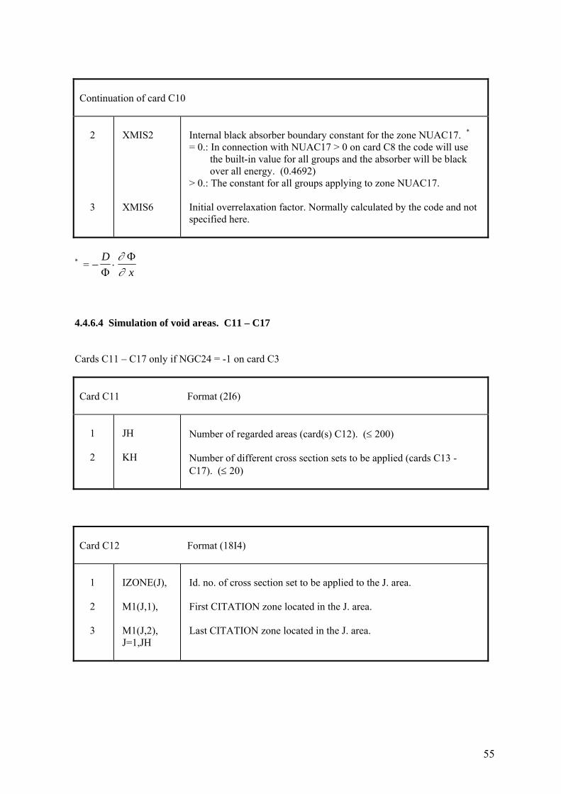
Continuation of card C10 2 3
XMIS2 XMIS6
Internal black absorber boundary constant for the zone NUAC17. * = 0.: In connection with NUAC17 > 0 on card C8 the code will use the built-in value for all groups and the absorber will be black over all energy. (0.4692) > 0.: The constant for all groups applying to zone NUAC17. Initial overrelaxation factor. Normally calculated by the code and not specified here.
* = − ⋅D
xΦΦ∂
∂
4.4.6.4 Simulation of void areas. C11 – C17 Cards C11 – C17 only if NGC24 = -1 on card C3
Card C11 Format (2I6) 1 2
JH KH
Number of regarded areas (card(s) C12). (≤ 200) Number of different cross section sets to be applied (cards C13 - C17). (≤ 20)
Card C12 Format (18I4) 1 2 3
IZONE(J), M1(J,1), M1(J,2), J=1,JH
Id. no. of cross section set to be applied to the J. area. First CITATION zone located in the J. area. Last CITATION zone located in the J. area.
56
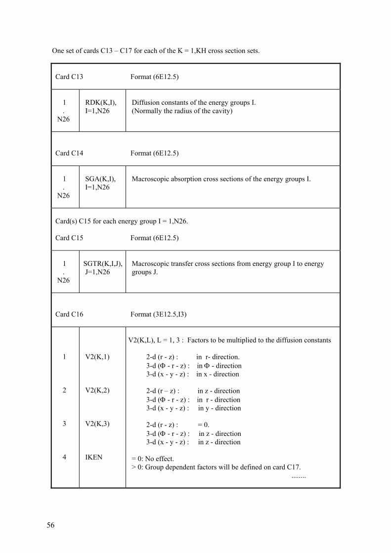
One set of cards C13 – C17 for each of the K = 1,KH cross section sets.
Card C13 Format (6E12.5) 1 . N26
RDK(K,I), I=1,N26
Diffusion constants of the energy groups I. (Normally the radius of the cavity)
Card C14 Format (6E12.5) 1 . N26
SGA(K,I), I=1,N26
Macroscopic absorption cross sections of the energy groups I.
Card(s) C15 for each energy group I = 1,N26. Card C15 Format (6E12.5) 1 . N26
SGTR(K,I,J), J=1,N26
Macroscopic transfer cross sections from energy group I to energy groups J.
Card C16 Format (3E12.5,I3) 1 2 3 4
V2(K,1) V2(K,2) V2(K,3) IKEN
V2(K,L), L = 1, 3 : Factors to be multiplied to the diffusion constants 2-d (r - z) : in r- direction. 3-d (Φ - r - z) : in Φ - direction 3-d (x - y - z) : in x - direction 2-d (r – z) : in z - direction 3-d (Φ - r - z) : in r - direction 3-d (x - y - z) : in y - direction 2-d (r - z) : = 0. 3-d (Φ - r - z) : in z - direction 3-d (x - y - z) : in z - direction = 0: No effect. > 0: Group dependent factors will be defined on card C17. ........
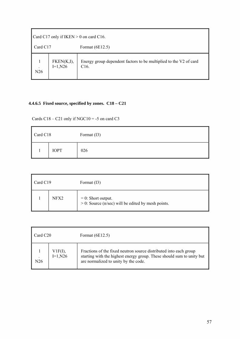
57
Card C17 only if IKEN > 0 on card C16. Card C17 Format (6E12.5)
1 . N26
FKEN(K,I), I=1,N26
Energy group dependent factors to be multiplied to the V2 of card C16.
4.4.6.5 Fixed source, specified by zones. C18 – C21 Cards C18 – C21 only if NGC10 = -5 on card C3
Card C18 Format (I3) 1
IOPT
026
Card C19 Format (I3) 1
NFX2
= 0: Short output. > 0: Source (n/sec) will be edited by mesh points.
Card C20 Format (6E12.5) 1 . N26
V1F(I), I=1,N26
Fractions of the fixed neutron source distributed into each group starting with the highest energy group. These should sum to unity but are normalized to unity by the code.
58
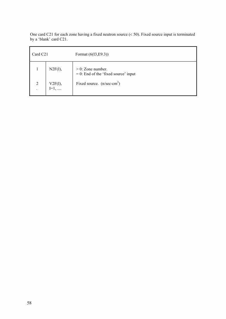
One card C21 for each zone having a fixed neutron source (< 50). Fixed source input is terminated by a ‘blank’ card C21.
Card C21 Format (6(I3,E9.3)) 1 2 .
N2F(I), V2F(I), I=1, ....
> 0: Zone number. = 0: End of the ‘fixed source’ input Fixed source. (n/sec-cm3)
59
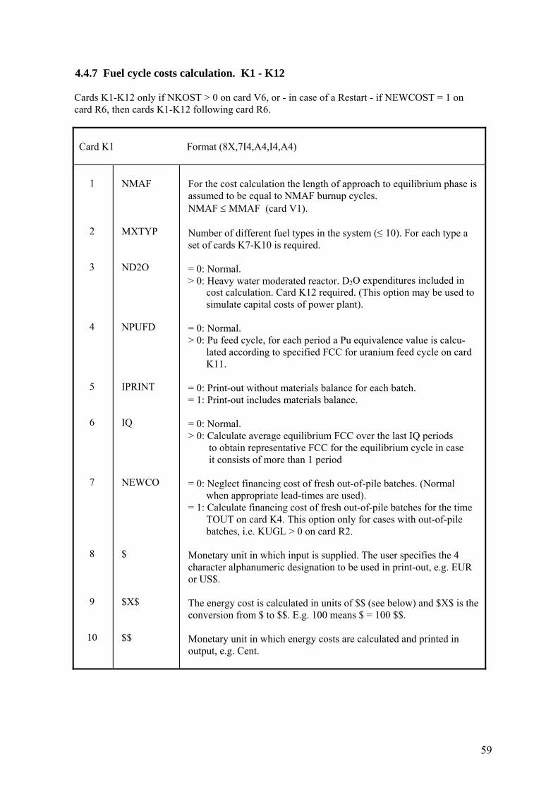
4.4.7 Fuel cycle costs calculation. K1 - K12 Cards K1-K12 only if NKOST > 0 on card V6, or - in case of a Restart - if NEWCOST = 1 on card R6, then cards K1-K12 following card R6.
Card K1 Format (8X,7I4,A4,I4,A4) 1 2 3 4 5 6 7 8 9 10
NMAF MXTYP ND2O NPUFD IPRINT IQ NEWCO $ $X$ $$
For the cost calculation the length of approach to equilibrium phase is assumed to be equal to NMAF burnup cycles. NMAF ≤ MMAF (card V1). Number of different fuel types in the system (≤ 10). For each type a set of cards K7-K10 is required. = 0: Normal. > 0: Heavy water moderated reactor. D2O expenditures included in cost calculation. Card K12 required. (This option may be used to simulate capital costs of power plant). = 0: Normal. > 0: Pu feed cycle, for each period a Pu equivalence value is calcu- lated according to specified FCC for uranium feed cycle on card K11. = 0: Print-out without materials balance for each batch. = 1: Print-out includes materials balance. = 0: Normal. > 0: Calculate average equilibrium FCC over the last IQ periods to obtain representative FCC for the equilibrium cycle in case it consists of more than 1 period = 0: Neglect financing cost of fresh out-of-pile batches. (Normal when appropriate lead-times are used). = 1: Calculate financing cost of fresh out-of-pile batches for the time TOUT on card K4. This option only for cases with out-of-pile batches, i.e. KUGL > 0 on card R2. Monetary unit in which input is supplied. The user specifies the 4 character alphanumeric designation to be used in print-out, e.g. EUR or US$. The energy cost is calculated in units of $$ (see below) and $X$ is the conversion from $ to $$. E.g. 100 means $ = 100 $$. Monetary unit in which energy costs are calculated and printed in output, e.g. Cent.
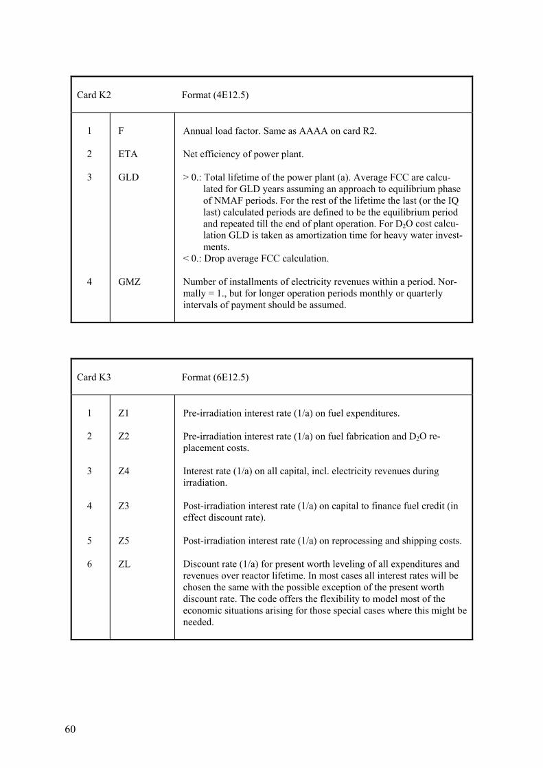
60
Card K2 Format (4E12.5) 1 2 3 4
F ETA GLD GMZ
Annual load factor. Same as AAAA on card R2. Net efficiency of power plant. > 0.: Total lifetime of the power plant (a). Average FCC are calcu- lated for GLD years assuming an approach to equilibrium phase of NMAF periods. For the rest of the lifetime the last (or the IQ last) calculated periods are defined to be the equilibrium period and repeated till the end of plant operation. For D2O cost calcu- lation GLD is taken as amortization time for heavy water invest- ments. < 0.: Drop average FCC calculation. Number of installments of electricity revenues within a period. Nor- mally = 1., but for longer operation periods monthly or quarterly intervals of payment should be assumed.
Card K3 Format (6E12.5) 1 2 3 4 5 6
Z1 Z2 Z4 Z3 Z5 ZL
Pre-irradiation interest rate (1/a) on fuel expenditures. Pre-irradiation interest rate (1/a) on fuel fabrication and D2O re- placement costs. Interest rate (1/a) on all capital, incl. electricity revenues during irradiation. Post-irradiation interest rate (1/a) on capital to finance fuel credit (in effect discount rate). Post-irradiation interest rate (1/a) on reprocessing and shipping costs. Discount rate (1/a) for present worth leveling of all expenditures and revenues over reactor lifetime. In most cases all interest rates will be chosen the same with the possible exception of the present worth discount rate. The code offers the flexibility to model most of the economic situations arising for those special cases where this might be needed.
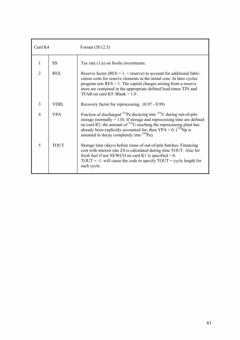
61
Card K4 Format (5E12.5) 1 2 3 4 5
SS RES VERL YPA TOUT
Tax rate (1/a) on fissile investments. Reserve factor (RES = 1. + reserve) to account for additional fabri- cation costs for reserve elements in the initial core. In later cycles program sets RES = 1. The capital charges arising from a reserve store are contained in the appropriate defined lead-times TIN and TFAB on card K9. Blank = 1.0 . Recovery factor for reprocessing. (0.97 - 0.99) Fraction of discharged 233Pa decaying into 233U during out-of-pile storage (normally = 1.0). If storage and reprocessing time are defined on card R2, the amount of 233U reaching the reprocessing plant has already been explicitly accounted for, then YPA = 0. (239Np is assumed to decay completely into 239Pu). Storage time (days) before reuse of out-of-pile batches. Financing cost with interest rate Z4 is calculated during time TOUT. Also for fresh fuel if not NEWCO on card K1 is specified = 0. TOUT = -1. will cause the code to specify TOUT = cycle length for each cycle.
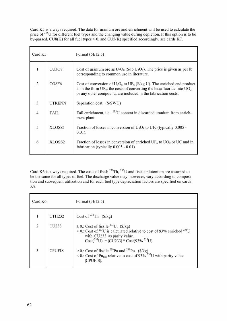
62
Card K5 is always required. The data for uranium ore and enrichment will be used to calculate the price of 235U for different fuel types and the changing value during depletion. If this option is to be by-passed, CU8(K) for all fuel types > 0. and CU5(K) specified accordingly, see cards K7.
Card K5 Format (6E12.5) 1 2 3 4 5 6
CU3O8 CO8F6 CTRENN TAIL XLOSS1 XLOSS2
Cost of uranium ore as U3O8 ($/lb U3O8). The price is given as per lb corresponding to common use in literature. Cost of conversion of U3O8 to UF6 ($/kg U). The enriched end product is in the form UF6, the costs of converting the hexafluoride into UO2 or any other compound, are included in the fabrication costs. Separation cost. ($/SWU) Tail enrichment, i.e., 235U content in discarded uranium from enrich- ment plant. Fraction of losses in conversion of U3O8 to UF6 (typically 0.005 - 0.01). Fraction of losses in conversion of enriched UF6 to UO2 or UC and in fabrication (typically 0.005 - 0.01).
Card K6 is always required. The costs of fresh 232Th, 233U and fissile plutonium are assumed to be the same for all types of fuel. The discharge value may, however, vary according to composi- tion and subsequent utilization and for each fuel type depreciation factors are specified on cards K8.
Card K6 Format (3E12.5) 1 2 3
CTH232 CU233 CPUFIS
Cost of 232Th. ($/kg) ≥ 0.: Cost of fissile 233U. ($/kg) < 0.: Cost of 233U is calculated relative to cost of 93% enriched 235U with |CU233| as parity value. Cost(233U) = |CU233| * Cost(93% 235U). ≥ 0.: Cost of fissile 239Pu and 241Pu. ($/kg) < 0.: Cost of Pufiss relative to cost of 93% 235U with parity value |CPUFIS|.
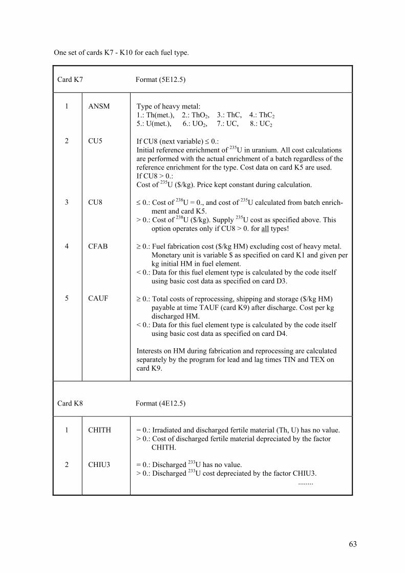
63
One set of cards K7 - K10 for each fuel type.
Card K7 Format (5E12.5) 1 2 3 4 5
ANSM CU5 CU8 CFAB CAUF
Type of heavy metal: 1.: Th(met.), 2.: ThO2, 3.: ThC, 4.: ThC2 5.: U(met.), 6.: UO2, 7.: UC, 8.: UC2 If CU8 (next variable) ≤ 0.: Initial reference enrichment of 235U in uranium. All cost calculations are performed with the actual enrichment of a batch regardless of the reference enrichment for the type. Cost data on card K5 are used. If CU8 > 0.: Cost of 235U ($/kg). Price kept constant during calculation. ≤ 0.: Cost of 238U = 0., and cost of 235U calculated from batch enrich- ment and card K5. > 0.: Cost of 238U ($/kg). Supply 235U cost as specified above. This option operates only if CU8 > 0. for all types! ≥ 0.: Fuel fabrication cost ($/kg HM) excluding cost of heavy metal. Monetary unit is variable $ as specified on card K1 and given per kg initial HM in fuel element. < 0.: Data for this fuel element type is calculated by the code itself using basic cost data as specified on card D3. ≥ 0.: Total costs of reprocessing, shipping and storage ($/kg HM) payable at time TAUF (card K9) after discharge. Cost per kg discharged HM. < 0.: Data for this fuel element type is calculated by the code itself using basic cost data as specified on card D4. Interests on HM during fabrication and reprocessing are calculated separately by the program for lead and lag times TIN and TEX on card K9.
Card K8 Format (4E12.5) 1 2
CHITH CHIU3
= 0.: Irradiated and discharged fertile material (Th, U) has no value. > 0.: Cost of discharged fertile material depreciated by the factor CHITH. = 0.: Discharged 233U has no value. > 0.: Discharged 233U cost depreciated by the factor CHIU3. ........
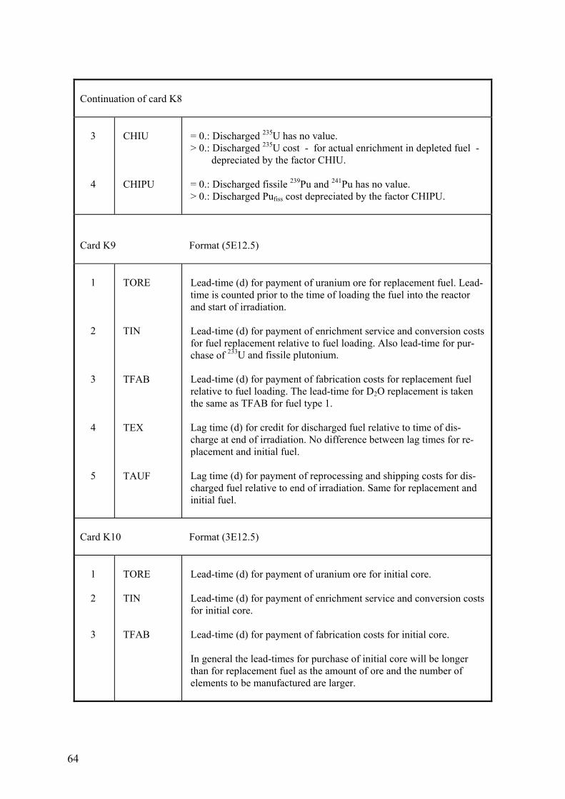
64
Continuation of card K8 3 4
CHIU CHIPU
= 0.: Discharged 235U has no value. > 0.: Discharged 235U cost - for actual enrichment in depleted fuel - depreciated by the factor CHIU. = 0.: Discharged fissile 239Pu and 241Pu has no value. > 0.: Discharged Pufiss cost depreciated by the factor CHIPU.
Card K9 Format (5E12.5) 1 2 3 4 5
TORE TIN TFAB TEX TAUF
Lead-time (d) for payment of uranium ore for replacement fuel. Lead- time is counted prior to the time of loading the fuel into the reactor and start of irradiation. Lead-time (d) for payment of enrichment service and conversion costs for fuel replacement relative to fuel loading. Also lead-time for pur- chase of 233U and fissile plutonium. Lead-time (d) for payment of fabrication costs for replacement fuel relative to fuel loading. The lead-time for D2O replacement is taken the same as TFAB for fuel type 1. Lag time (d) for credit for discharged fuel relative to time of dis- charge at end of irradiation. No difference between lag times for re- placement and initial fuel. Lag time (d) for payment of reprocessing and shipping costs for dis- charged fuel relative to end of irradiation. Same for replacement and initial fuel.
Card K10 Format (3E12.5) 1 2 3
TORE TIN TFAB
Lead-time (d) for payment of uranium ore for initial core. Lead-time (d) for payment of enrichment service and conversion costs for initial core. Lead-time (d) for payment of fabrication costs for initial core. In general the lead-times for purchase of initial core will be longer than for replacement fuel as the amount of ore and the number of elements to be manufactured are larger.
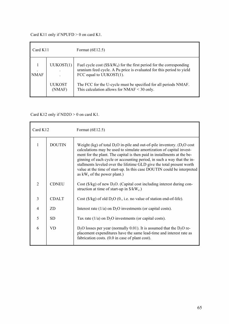
65
Card K11 only if NPUFD > 0 on card K1.
Card K11 Format (6E12.5) 1 . NMAF
UUKOST(1) . . UUKOST (NMAF)
Fuel cycle cost ($$/kWh) for the first period for the corresponding uranium feed cycle. A Pu price is evaluated for this period to yield FCC equal to UUKOST(1). The FCC for the U-cycle must be specified for all periods NMAF. This calculation allows for NMAF < 30 only.
Card K12 only if ND2O > 0 on card K1.
Card K12 Format (6E12.5) 1 2 3 4 5 6
DOUTIN CDNEU CDALT ZD SD VD
Weight (kg) of total D2O in-pile and out-of-pile inventory. (D2O cost calculations may be used to simulate amortization of capital invest- ment for the plant. The capital is then paid in installments at the be- ginning of each cycle or accounting period, in such a way that the in- stallments leveled over the lifetime GLD give the total present worth value at the time of start-up. In this case DOUTIN could be interpreted as kWe of the power plant.) Cost ($/kg) of new D2O. (Capital cost including interest during con- struction at time of start-up in $/kWe.) Cost ($/kg) of old D2O (0., i.e. no value of station end-of-life). Interest rate (1/a) on D2O investments (or capital costs). Tax rate (1/a) on D2O investments (or capital costs). D2O losses per year (normally 0.01). It is assumed that the D2O re- placement expenditures have the same lead-time and interest rate as fabrication costs. (0.0 in case of plant cost).
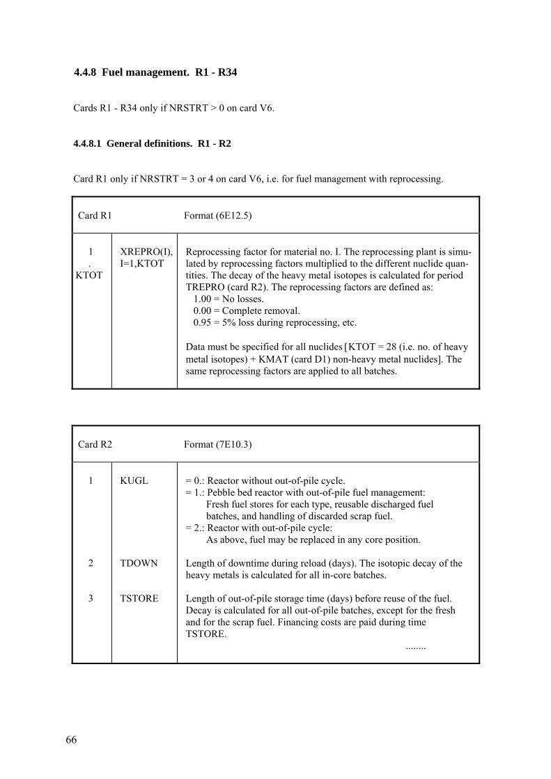
66
4.4.8 Fuel management. R1 - R34 Cards R1 - R34 only if NRSTRT > 0 on card V6. 4.4.8.1 General definitions. R1 - R2 Card R1 only if NRSTRT = 3 or 4 on card V6, i.e. for fuel management with reprocessing.
Card R1 Format (6E12.5) 1 . KTOT
XREPRO(I), I=1,KTOT
Reprocessing factor for material no. I. The reprocessing plant is simu- lated by reprocessing factors multiplied to the different nuclide quan- tities. The decay of the heavy metal isotopes is calculated for period TREPRO (card R2). The reprocessing factors are defined as: 1.00 = No losses. 0.00 = Complete removal. 0.95 = 5% loss during reprocessing, etc. Data must be specified for all nuclides [KTOT = 28 (i.e. no. of heavy metal isotopes) + KMAT (card D1) non-heavy metal nuclides]. The same reprocessing factors are applied to all batches.
Card R2 Format (7E10.3) 1 2 3
KUGL TDOWN TSTORE
= 0.: Reactor without out-of-pile cycle. = 1.: Pebble bed reactor with out-of-pile fuel management: Fresh fuel stores for each type, reusable discharged fuel batches, and handling of discarded scrap fuel. = 2.: Reactor with out-of-pile cycle: As above, fuel may be replaced in any core position. Length of downtime during reload (days). The isotopic decay of the heavy metals is calculated for all in-core batches. Length of out-of-pile storage time (days) before reuse of the fuel. Decay is calculated for all out-of-pile batches, except for the fresh and for the scrap fuel. Financing costs are paid during time TSTORE. ........
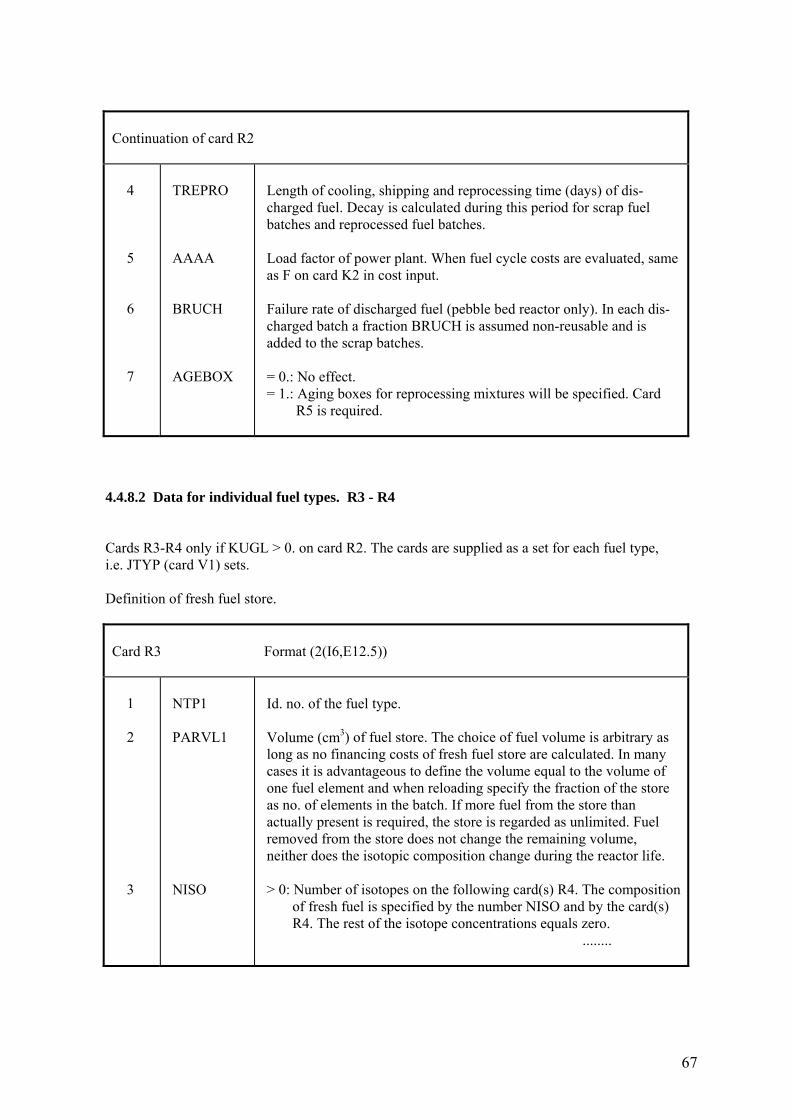
67
Continuation of card R2 4 5 6 7
TREPRO AAAA BRUCH AGEBOX
Length of cooling, shipping and reprocessing time (days) of dis- charged fuel. Decay is calculated during this period for scrap fuel batches and reprocessed fuel batches. Load factor of power plant. When fuel cycle costs are evaluated, same as F on card K2 in cost input. Failure rate of discharged fuel (pebble bed reactor only). In each dis- charged batch a fraction BRUCH is assumed non-reusable and is added to the scrap batches. = 0.: No effect. = 1.: Aging boxes for reprocessing mixtures will be specified. Card R5 is required.
4.4.8.2 Data for individual fuel types. R3 - R4 Cards R3-R4 only if KUGL > 0. on card R2. The cards are supplied as a set for each fuel type, i.e. JTYP (card V1) sets. Definition of fresh fuel store.
Card R3 Format (2(I6,E12.5)) 1 2 3
NTP1 PARVL1 NISO
Id. no. of the fuel type. Volume (cm3) of fuel store. The choice of fuel volume is arbitrary as long as no financing costs of fresh fuel store are calculated. In many cases it is advantageous to define the volume equal to the volume of one fuel element and when reloading specify the fraction of the store as no. of elements in the batch. If more fuel from the store than actually present is required, the store is regarded as unlimited. Fuel removed from the store does not change the remaining volume, neither does the isotopic composition change during the reactor life. > 0: Number of isotopes on the following card(s) R4. The composition of fresh fuel is specified by the number NISO and by the card(s) R4. The rest of the isotope concentrations equals zero. ........
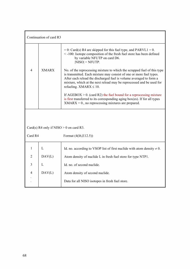
68
Continuation of card R3 4
XMARX
= 0: Card(s) R4 are skipped for this fuel type, and PARVL1 = 0. < -100: Isotope composition of the fresh fuel store has been defined by variable NFUTP on card D6. |NISO| = NFUTP. No. of the reprocessing mixture to which the scrapped fuel of this type is transmitted. Each mixture may consist of one or more fuel types. After each reload the discharged fuel is volume averaged to form a mixture, which at the next reload may be reprocessed and be used for refueling. XMARX ≤ 10. If AGEBOX > 0. (card R2) the fuel bound for a reprocessing mixture is first transferred to its corresponding aging box(es). If for all types XMARX = 0., no reprocessing mixtures are prepared.
Card(s) R4 only if NISO > 0 on card R3. Card R4 Format (4(I6,E12.5)) 1 2 3 4 . .
L DAV(L) L DAV(L)
Id. no. according to VSOP list of first nuclide with atom density ≠ 0. Atom density of nuclide L in fresh fuel store for type NTP1. Id. no. of second nuclide. Atom density of second nuclide. Data for all NISO isotopes in fresh fuel store.
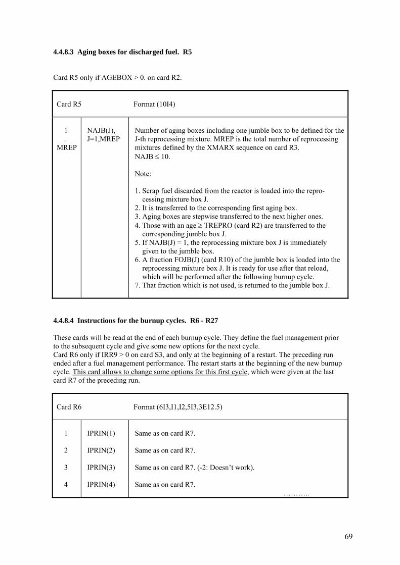
69
4.4.8.3 Aging boxes for discharged fuel. R5 Card R5 only if AGEBOX > 0. on card R2.
Card R5 Format (10I4) 1 . MREP
NAJB(J), J=1,MREP
Number of aging boxes including one jumble box to be defined for the J-th reprocessing mixture. MREP is the total number of reprocessing mixtures defined by the XMARX sequence on card R3. NAJB ≤ 10. Note: 1. Scrap fuel discarded from the reactor is loaded into the repro- cessing mixture box J. 2. It is transferred to the corresponding first aging box. 3. Aging boxes are stepwise transferred to the next higher ones. 4. Those with an age ≥ TREPRO (card R2) are transferred to the corresponding jumble box J. 5. If NAJB(J) = 1, the reprocessing mixture box J is immediately given to the jumble box. 6. A fraction FOJB(J) (card R10) of the jumble box is loaded into the reprocessing mixture box J. It is ready for use after that reload, which will be performed after the following burnup cycle. 7. That fraction which is not used, is returned to the jumble box J.
4.4.8.4 Instructions for the burnup cycles. R6 - R27 These cards will be read at the end of each burnup cycle. They define the fuel management prior to the subsequent cycle and give some new options for the next cycle. Card R6 only if IRR9 > 0 on card S3, and only at the beginning of a restart. The preceding run ended after a fuel management performance. The restart starts at the beginning of the new burnup cycle. This card allows to change some options for this first cycle, which were given at the last card R7 of the preceding run.
Card R6 Format (6I3,I1,I2,5I3,3E12.5) 1 2 3 4
IPRIN(1) IPRIN(2) IPRIN(3) IPRIN(4)
Same as on card R7. Same as on card R7. Same as on card R7. (-2: Doesn’t work). Same as on card R7. ………..
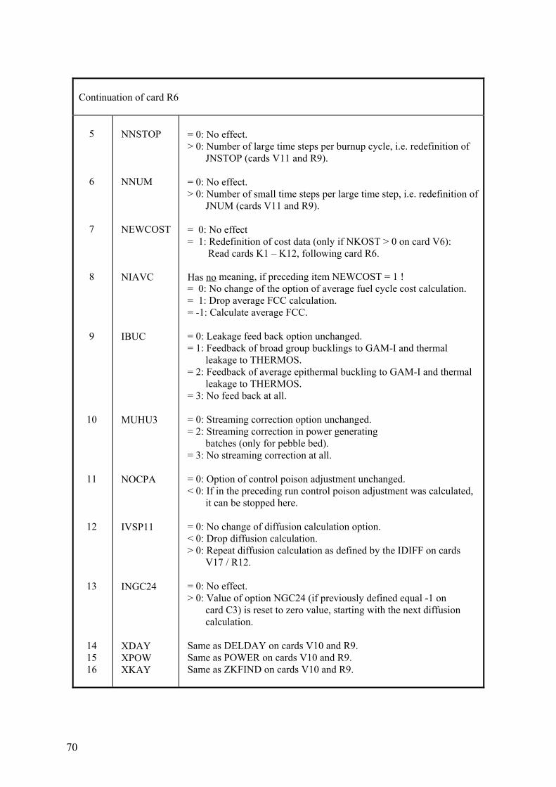
70
Continuation of card R6 5 6 7 8 9 10 11 12 13 14 15 16
NNSTOP NNUM NEWCOST NIAVC IBUC MUHU3 NOCPA IVSP11 INGC24 XDAY XPOW XKAY
= 0: No effect. > 0: Number of large time steps per burnup cycle, i.e. redefinition of JNSTOP (cards V11 and R9). = 0: No effect. > 0: Number of small time steps per large time step, i.e. redefinition of JNUM (cards V11 and R9). = 0: No effect = 1: Redefinition of cost data (only if NKOST > 0 on card V6): Read cards K1 – K12, following card R6. Has no meaning, if preceding item NEWCOST = 1 ! = 0: No change of the option of average fuel cycle cost calculation. = 1: Drop average FCC calculation. = -1: Calculate average FCC. = 0: Leakage feed back option unchanged. = 1: Feedback of broad group bucklings to GAM-I and thermal leakage to THERMOS. = 2: Feedback of average epithermal buckling to GAM-I and thermal leakage to THERMOS. = 3: No feed back at all. = 0: Streaming correction option unchanged. = 2: Streaming correction in power generating batches (only for pebble bed). = 3: No streaming correction at all. = 0: Option of control poison adjustment unchanged. < 0: If in the preceding run control poison adjustment was calculated, it can be stopped here. = 0: No change of diffusion calculation option. < 0: Drop diffusion calculation. > 0: Repeat diffusion calculation as defined by the IDIFF on cards V17 / R12. = 0: No effect. > 0: Value of option NGC24 (if previously defined equal -1 on card C3) is reset to zero value, starting with the next diffusion calculation. Same as DELDAY on cards V10 and R9. Same as POWER on cards V10 and R9. Same as ZKFIND on cards V10 and R9.
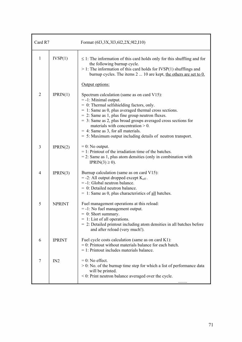
71
Card R7 Format (6I3,3X,3I3,6I2,2X,9I2,I10) 1 2 3 4 5 6 7
IVSP(1) IPRIN(1) IPRIN(2) IPRIN(3) NPRINT IPRINT IN2
≤ 1: The information of this card holds only for this shuffling and for the following burnup cycle. > 1: The information of this card holds for IVSP(1) shufflings and burnup cycles. The items 2 ... 10 are kept, the others are set to 0. Output options: Spectrum calculation (same as on card V15): = -1: Minimal output. = 0: Thermal selfshielding factors, only. = 1: Same as 0, plus averaged thermal cross sections. = 2: Same as 1, plus fine group neutron fluxes. = 3: Same as 2, plus broad groups averaged cross sections for materials with concentration > 0. = 4: Same as 3, for all materials. = 5: Maximum output including details of neutron transport. = 0: No output. = 1: Printout of the irradiation time of the batches. = 2: Same as 1, plus atom densities (only in combination with IPRIN(3) ≥ 0). Burnup calculation (same as on card V15): = -2: All output dropped except Keff . = -1: Global neutron balance. = 0: Detailed neutron balance. = 1: Same as 0, plus characteristics of all batches. Fuel management operations at this reload: = -1: No fuel management output. = 0: Short summary. = 1: List of all operations. = 2: Detailed printout including atom densities in all batches before and after reload (very much!). Fuel cycle costs calculation (same as on card K1): = 0: Printout without materials balance for each batch. = 1: Printout includes materials balance. = 0: No effect. > 0: No. of the burnup time step for which a list of performance data will be printed. < 0: Print neutron balance averaged over the cycle. ........
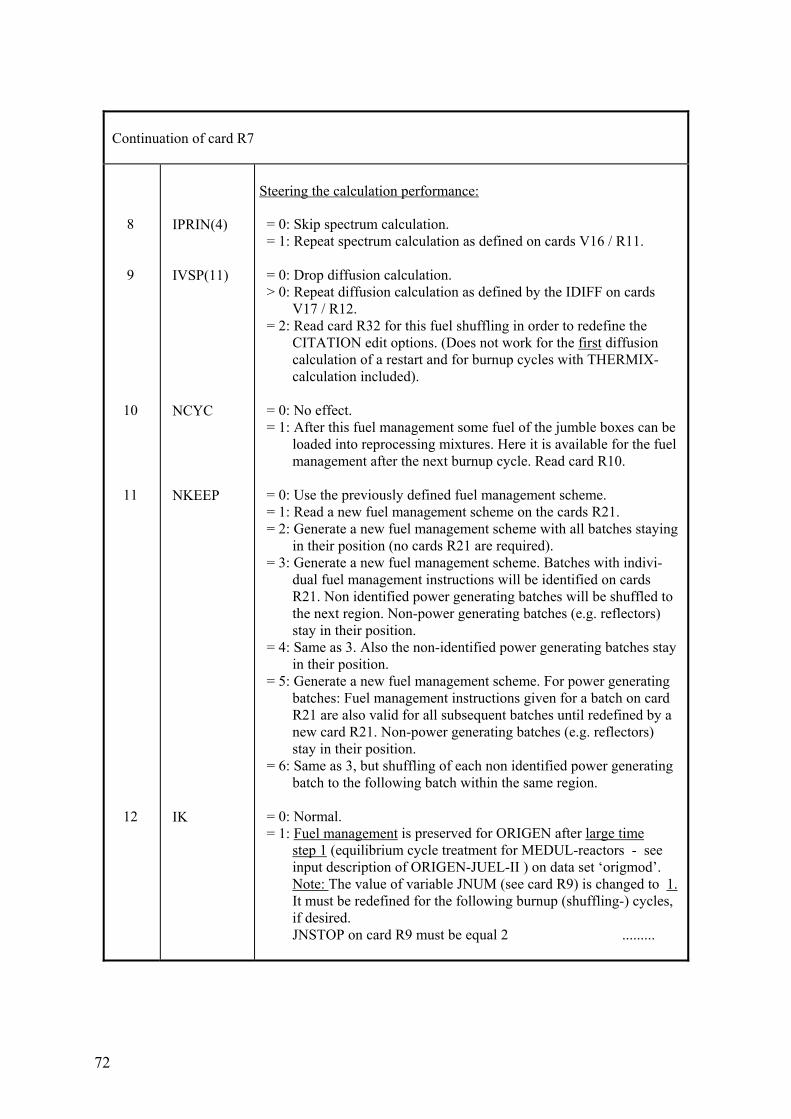
72
Continuation of card R7 8 9 10 11 12
IPRIN(4) IVSP(11) NCYC NKEEP IK
Steering the calculation performance: = 0: Skip spectrum calculation. = 1: Repeat spectrum calculation as defined on cards V16 / R11. = 0: Drop diffusion calculation. > 0: Repeat diffusion calculation as defined by the IDIFF on cards V17 / R12. = 2: Read card R32 for this fuel shuffling in order to redefine the CITATION edit options. (Does not work for the first diffusion calculation of a restart and for burnup cycles with THERMIX- calculation included). = 0: No effect. = 1: After this fuel management some fuel of the jumble boxes can be loaded into reprocessing mixtures. Here it is available for the fuel management after the next burnup cycle. Read card R10. = 0: Use the previously defined fuel management scheme. = 1: Read a new fuel management scheme on the cards R21. = 2: Generate a new fuel management scheme with all batches staying in their position (no cards R21 are required). = 3: Generate a new fuel management scheme. Batches with indivi- dual fuel management instructions will be identified on cards R21. Non identified power generating batches will be shuffled to the next region. Non-power generating batches (e.g. reflectors) stay in their position. = 4: Same as 3. Also the non-identified power generating batches stay in their position. = 5: Generate a new fuel management scheme. For power generating batches: Fuel management instructions given for a batch on card R21 are also valid for all subsequent batches until redefined by a new card R21. Non-power generating batches (e.g. reflectors) stay in their position. = 6: Same as 3, but shuffling of each non identified power generating batch to the following batch within the same region. = 0: Normal. = 1: Fuel management is preserved for ORIGEN after large time step 1 (equilibrium cycle treatment for MEDUL-reactors - see input description of ORIGEN-JUEL-II ) on data set ‘origmod’. Note: The value of variable JNUM (see card R9) is changed to 1. It must be redefined for the following burnup (shuffling-) cycles, if desired. JNSTOP on card R9 must be equal 2 .........
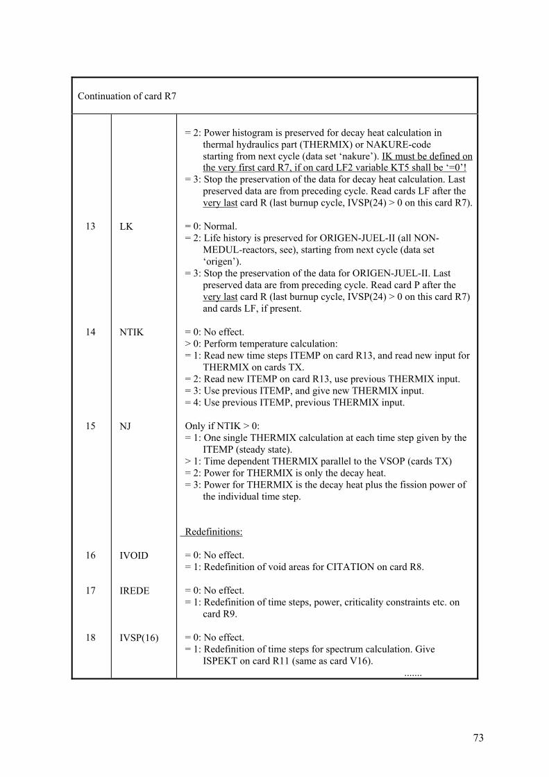
73
Continuation of card R7 13 14 15 16 17 18
LK NTIK NJ IVOID IREDE IVSP(16)
= 2: Power histogram is preserved for decay heat calculation in thermal hydraulics part (THERMIX) or NAKURE-code starting from next cycle (data set ‘nakure’). IK must be defined on the very first card R7, if on card LF2 variable KT5 shall be ‘=0’! = 3: Stop the preservation of the data for decay heat calculation. Last preserved data are from preceding cycle. Read cards LF after the very last card R (last burnup cycle, IVSP(24) > 0 on this card R7). = 0: Normal. = 2: Life history is preserved for ORIGEN-JUEL-II (all NON- MEDUL-reactors, see), starting from next cycle (data set ‘origen’). = 3: Stop the preservation of the data for ORIGEN-JUEL-II. Last preserved data are from preceding cycle. Read card P after the very last card R (last burnup cycle, IVSP(24) > 0 on this card R7) and cards LF, if present. = 0: No effect. > 0: Perform temperature calculation: = 1: Read new time steps ITEMP on card R13, and read new input for THERMIX on cards TX. = 2: Read new ITEMP on card R13, use previous THERMIX input. = 3: Use previous ITEMP, and give new THERMIX input. = 4: Use previous ITEMP, previous THERMIX input. Only if NTIK > 0: = 1: One single THERMIX calculation at each time step given by the ITEMP (steady state). > 1: Time dependent THERMIX parallel to the VSOP (cards TX) = 2: Power for THERMIX is only the decay heat. = 3: Power for THERMIX is the decay heat plus the fission power of the individual time step. Redefinitions: = 0: No effect. = 1: Redefinition of void areas for CITATION on card R8. = 0: No effect. = 1: Redefinition of time steps, power, criticality constraints etc. on card R9. = 0: No effect. = 1: Redefinition of time steps for spectrum calculation. Give ISPEKT on card R11 (same as card V16). .......
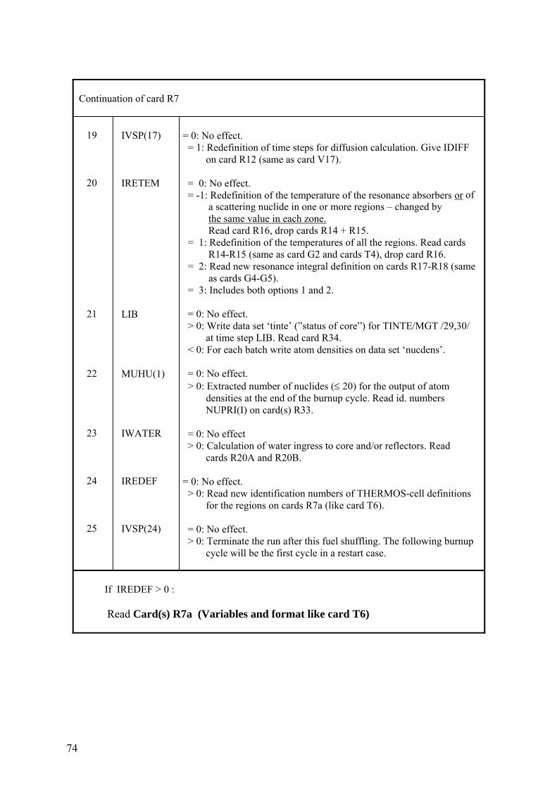
74
Continuation of card R7 19 20 21 22 23 24 25
IVSP(17) IRETEM LIB MUHU(1) IWATER IREDEF IVSP(24)
= 0: No effect. = 1: Redefinition of time steps for diffusion calculation. Give IDIFF on card R12 (same as card V17). = 0: No effect. = -1: Redefinition of the temperature of the resonance absorbers or of a scattering nuclide in one or more regions – changed by the same value in each zone. Read card R16, drop cards R14 + R15. = 1: Redefinition of the temperatures of all the regions. Read cards R14-R15 (same as card G2 and cards T4), drop card R16. = 2: Read new resonance integral definition on cards R17-R18 (same as cards G4-G5). = 3: Includes both options 1 and 2. = 0: No effect. > 0: Write data set ‘tinte’ (”status of core”) for TINTE/MGT /29,30/ at time step LIB. Read card R34. < 0: For each batch write atom densities on data set ‘nucdens’. = 0: No effect. > 0: Extracted number of nuclides (≤ 20) for the output of atom densities at the end of the burnup cycle. Read id. numbers NUPRI(I) on card(s) R33. = 0: No effect > 0: Calculation of water ingress to core and/or reflectors. Read cards R20A and R20B. = 0: No effect. > 0: Read new identification numbers of THERMOS-cell definitions for the regions on cards R7a (like card T6). = 0: No effect. > 0: Terminate the run after this fuel shuffling. The following burnup cycle will be the first cycle in a restart case.
If IREDEF > 0 : Read Card(s) R7a (Variables and format like card T6)
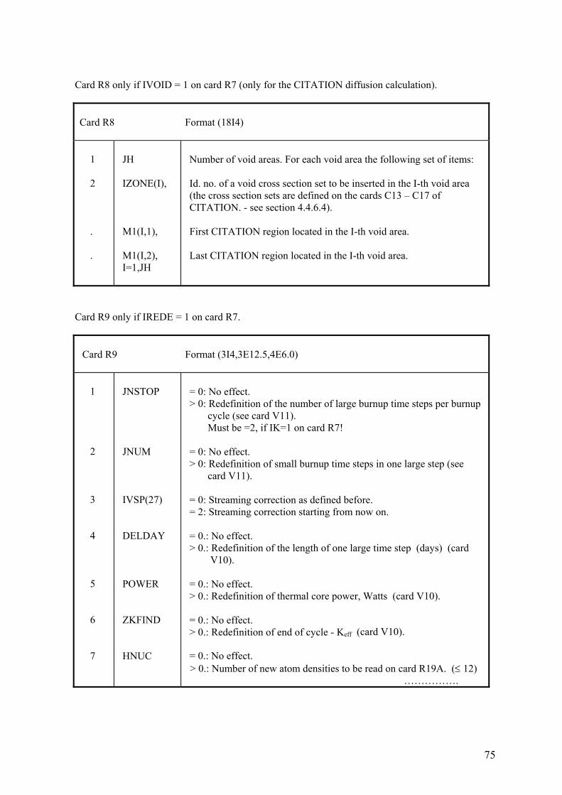
75
Card R8 only if IVOID = 1 on card R7 (only for the CITATION diffusion calculation).
Card R8 Format (18I4) 1 2 . .
JH IZONE(I), M1(I,1), M1(I,2), I=1,JH
Number of void areas. For each void area the following set of items: Id. no. of a void cross section set to be inserted in the I-th void area (the cross section sets are defined on the cards C13 – C17 of CITATION. - see section 4.4.6.4). First CITATION region located in the I-th void area. Last CITATION region located in the I-th void area.
Card R9 only if IREDE = 1 on card R7.
Card R9 Format (3I4,3E12.5,4E6.0) 1 2 3 4 5 6 7
JNSTOP JNUM IVSP(27) DELDAY POWER ZKFIND HNUC
= 0: No effect. > 0: Redefinition of the number of large burnup time steps per burnup cycle (see card V11). Must be =2, if IK=1 on card R7! = 0: No effect. > 0: Redefinition of small burnup time steps in one large step (see card V11). = 0: Streaming correction as defined before. = 2: Streaming correction starting from now on. = 0.: No effect. > 0.: Redefinition of the length of one large time step (days) (card V10). = 0.: No effect. > 0.: Redefinition of thermal core power, Watts (card V10). = 0.: No effect. > 0.: Redefinition of end of cycle - Keff (card V10). = 0.: No effect.
> 0.: Number of new atom densities to be read on card R19A. (≤ 12) …………….
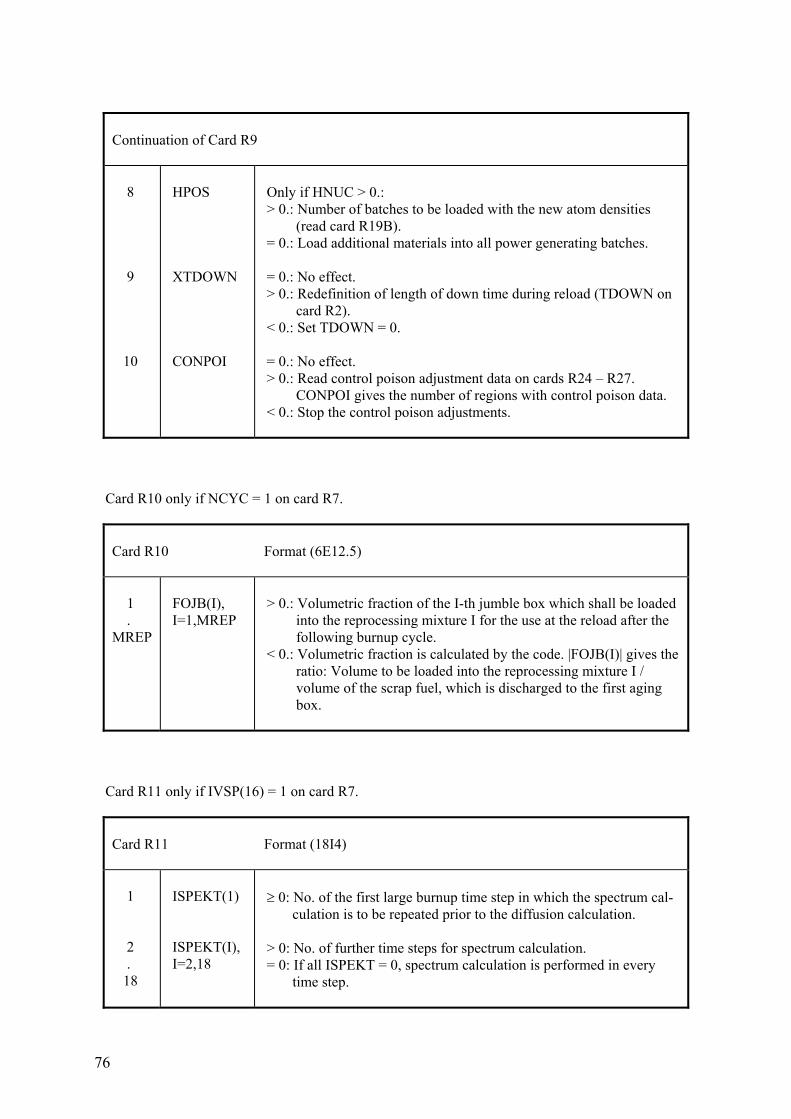
76
Continuation of Card R9 8 9 10
HPOS XTDOWN CONPOI
Only if HNUC > 0.: > 0.: Number of batches to be loaded with the new atom densities (read card R19B). = 0.: Load additional materials into all power generating batches. = 0.: No effect. > 0.: Redefinition of length of down time during reload (TDOWN on card R2). < 0.: Set TDOWN = 0. = 0.: No effect. > 0.: Read control poison adjustment data on cards R24 – R27. CONPOI gives the number of regions with control poison data. < 0.: Stop the control poison adjustments.
Card R10 only if NCYC = 1 on card R7.
Card R10 Format (6E12.5) 1 . MREP
FOJB(I), I=1,MREP
> 0.: Volumetric fraction of the I-th jumble box which shall be loaded into the reprocessing mixture I for the use at the reload after the following burnup cycle. < 0.: Volumetric fraction is calculated by the code. |FOJB(I)| gives the ratio: Volume to be loaded into the reprocessing mixture I / volume of the scrap fuel, which is discharged to the first aging box.
Card R11 only if IVSP(16) = 1 on card R7.
Card R11 Format (18I4) 1 2 . 18
ISPEKT(1) ISPEKT(I), I=2,18
≥ 0: No. of the first large burnup time step in which the spectrum cal- culation is to be repeated prior to the diffusion calculation. > 0: No. of further time steps for spectrum calculation. = 0: If all ISPEKT = 0, spectrum calculation is performed in every time step.
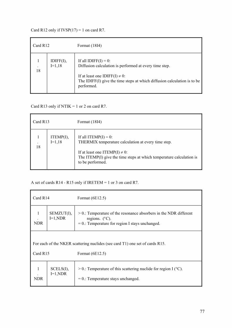
77
Card R12 only if IVSP(17) = 1 on card R7.
Card R12 Format (18I4) 1 . 18
IDIFF(I), I=1,18
If all IDIFF(I) = 0: Diffusion calculation is performed at every time step. If at least one IDIFF(I) ≠ 0: The IDIFF(I) give the time steps at which diffusion calculation is to be performed.
Card R13 only if NTIK = 1 or 2 on card R7.
Card R13 Format (18I4) 1 . 18
ITEMP(I), I=1,18
If all ITEMP(I) = 0: THERMIX temperature calculation at every time step. If at least one ITEMP(I) ≠ 0: The ITEMP(I) give the time steps at which temperature calculation is to be performed.
A set of cards R14 - R15 only if IRETEM = 1 or 3 on card R7.
Card R14 Format (6E12.5) 1 . NDR
SEMZUT(I), I=1,NDR
> 0.: Temperature of the resonance absorbers in the NDR different regions. (°C). = 0.: Temperature for region I stays unchanged.
For each of the NKER scattering nuclides (see card T1) one set of cards R15. Card R15 Format (6E12.5) 1 . NDR
SCELS(I), I=1,NDR
> 0.: Temperature of this scattering nuclide for region I (°C). = 0.: Temperature stays unchanged.
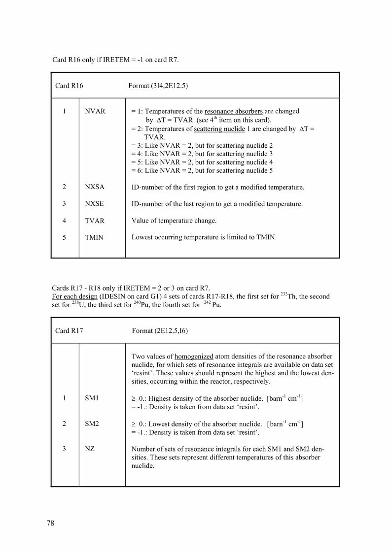
78
Card R16 only if IRETEM = -1 on card R7.
Card R16 Format (3I4,2E12.5) 1 2 3 4 5
NVAR NXSA NXSE TVAR TMIN
= 1: Temperatures of the resonance absorbers are changed by ΔT = TVAR (see 4th item on this card). = 2: Temperatures of scattering nuclide 1 are changed by ΔT = TVAR. = 3: Like NVAR = 2, but for scattering nuclide 2 = 4: Like NVAR = 2, but for scattering nuclide 3 = 5: Like NVAR = 2, but for scattering nuclide 4 = 6: Like NVAR = 2, but for scattering nuclide 5 ID-number of the first region to get a modified temperature. ID-number of the last region to get a modified temperature. Value of temperature change. Lowest occurring temperature is limited to TMIN.
Cards R17 - R18 only if IRETEM = 2 or 3 on card R7. For each design (IDESIN on card G1) 4 sets of cards R17-R18, the first set for 232Th, the second set for 238U, the third set for 240Pu, the fourth set for 242 Pu.
Card R17 Format (2E12.5,I6) 1 2 3
SM1 SM2 NZ
Two values of homogenized atom densities of the resonance absorber nuclide, for which sets of resonance integrals are available on data set ‘resint’. These values should represent the highest and the lowest den- sities, occurring within the reactor, respectively. ≥ 0.: Highest density of the absorber nuclide. [barn-1 cm-1] = -1.: Density is taken from data set ‘resint’. ≥ 0.: Lowest density of the absorber nuclide. [barn-1 cm-1] = -1.: Density is taken from data set ‘resint’. Number of sets of resonance integrals for each SM1 and SM2 den- sities. These sets represent different temperatures of this absorber nuclide.
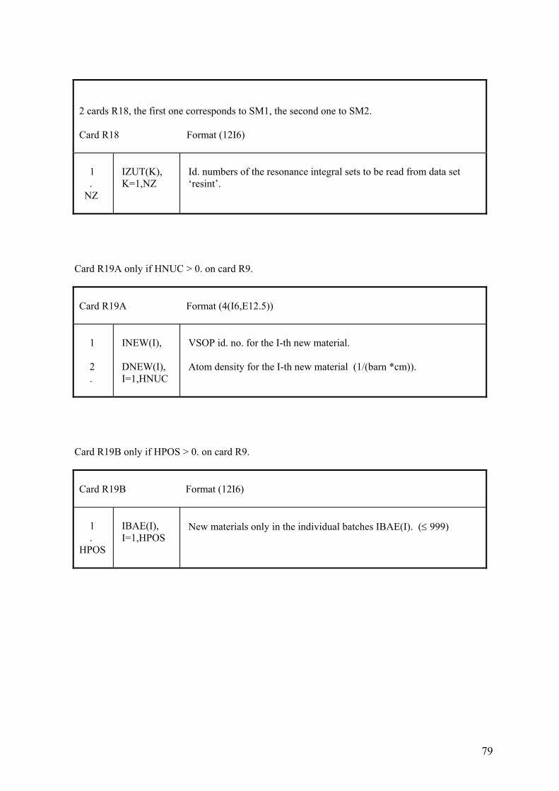
79
2 cards R18, the first one corresponds to SM1, the second one to SM2. Card R18 Format (12I6) 1 . NZ
IZUT(K), K=1,NZ
Id. numbers of the resonance integral sets to be read from data set ‘resint’.
Card R19A only if HNUC > 0. on card R9.
Card R19A Format (4(I6,E12.5)) 1 2 .
INEW(I), DNEW(I), I=1,HNUC
VSOP id. no. for the I-th new material. Atom density for the I-th new material (1/(barn *cm)).
Card R19B only if HPOS > 0. on card R9.
Card R19B Format (12I6) 1 . HPOS
IBAE(I), I=1,HPOS
New materials only in the individual batches IBAE(I). (≤ 999)
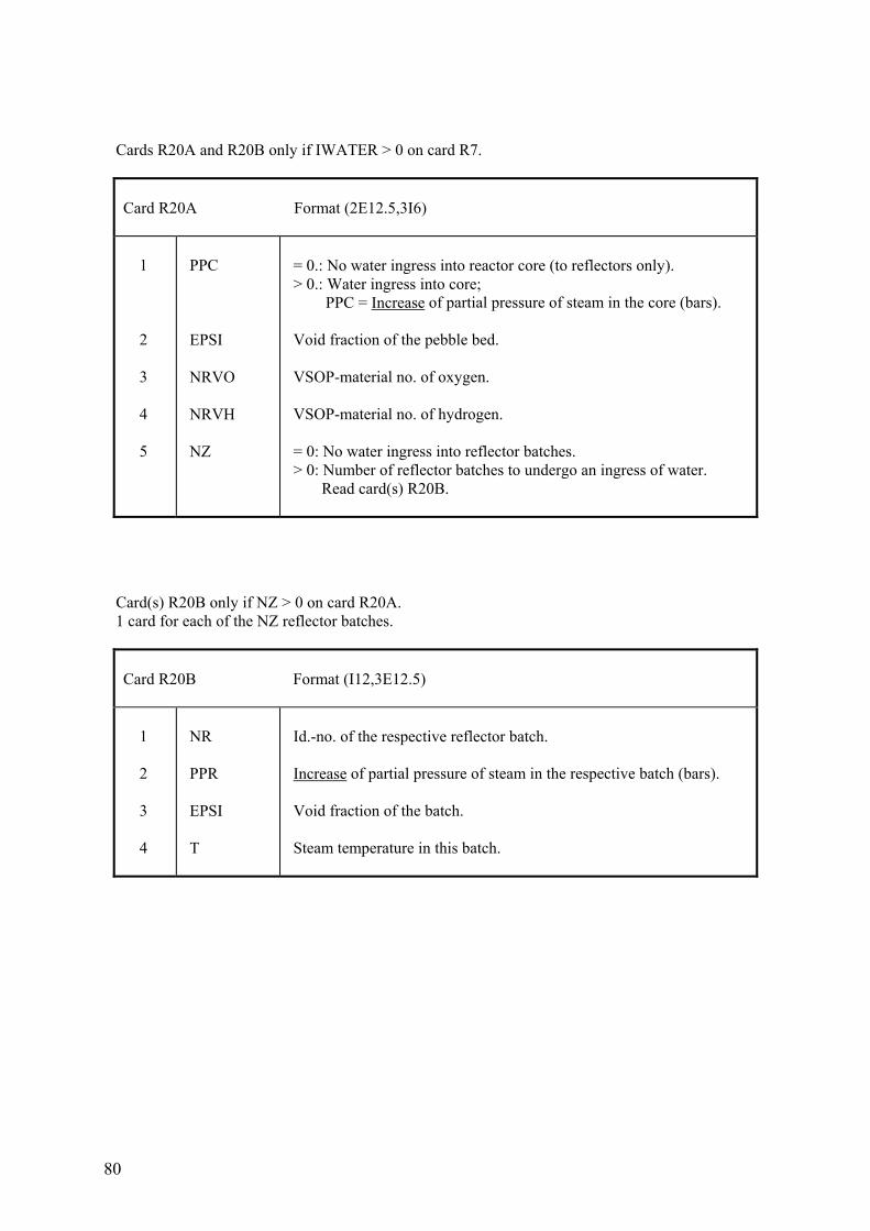
80
Cards R20A and R20B only if IWATER > 0 on card R7.
Card R20A Format (2E12.5,3I6) 1 2 3 4 5
PPC EPSI NRVO NRVH NZ
= 0.: No water ingress into reactor core (to reflectors only). > 0.: Water ingress into core; PPC = Increase of partial pressure of steam in the core (bars). Void fraction of the pebble bed. VSOP-material no. of oxygen. VSOP-material no. of hydrogen. = 0: No water ingress into reflector batches. > 0: Number of reflector batches to undergo an ingress of water. Read card(s) R20B.
Card(s) R20B only if NZ > 0 on card R20A. 1 card for each of the NZ reflector batches.
Card R20B Format (I12,3E12.5) 1 2 3 4
NR PPR EPSI T
Id.-no. of the respective reflector batch. Increase of partial pressure of steam in the respective batch (bars). Void fraction of the batch. Steam temperature in this batch.
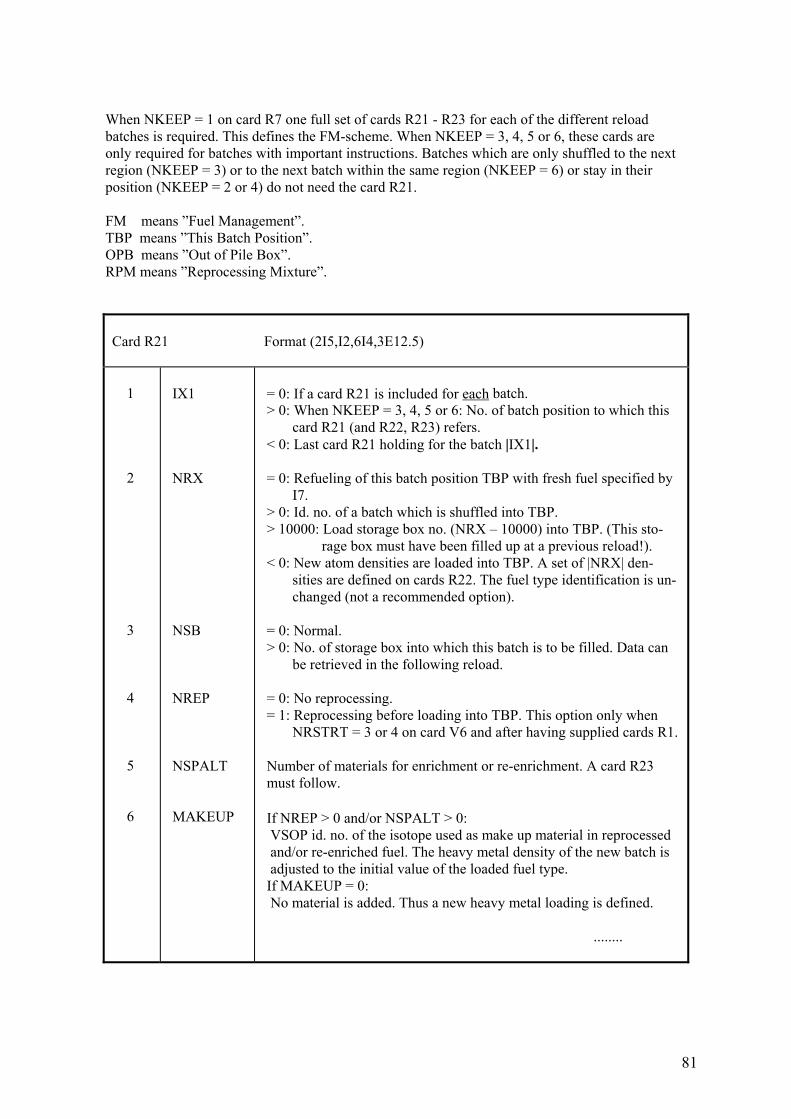
81
When NKEEP = 1 on card R7 one full set of cards R21 - R23 for each of the different reload batches is required. This defines the FM-scheme. When NKEEP = 3, 4, 5 or 6, these cards are only required for batches with important instructions. Batches which are only shuffled to the next region (NKEEP = 3) or to the next batch within the same region (NKEEP = 6) or stay in their position (NKEEP = 2 or 4) do not need the card R21. FM means ”Fuel Management”. TBP means ”This Batch Position”. OPB means ”Out of Pile Box”. RPM means ”Reprocessing Mixture”.
Card R21 Format (2I5,I2,6I4,3E12.5) 1 2 3 4 5 6
IX1 NRX NSB NREP NSPALT MAKEUP
= 0: If a card R21 is included for each batch. > 0: When NKEEP = 3, 4, 5 or 6: No. of batch position to which this card R21 (and R22, R23) refers. < 0: Last card R21 holding for the batch |IX1|. = 0: Refueling of this batch position TBP with fresh fuel specified by I7. > 0: Id. no. of a batch which is shuffled into TBP. > 10000: Load storage box no. (NRX – 10000) into TBP. (This sto- rage box must have been filled up at a previous reload!). < 0: New atom densities are loaded into TBP. A set of |NRX| den- sities are defined on cards R22. The fuel type identification is un- changed (not a recommended option). = 0: Normal. > 0: No. of storage box into which this batch is to be filled. Data can be retrieved in the following reload. = 0: No reprocessing. = 1: Reprocessing before loading into TBP. This option only when NRSTRT = 3 or 4 on card V6 and after having supplied cards R1. Number of materials for enrichment or re-enrichment. A card R23 must follow. If NREP > 0 and/or NSPALT > 0: VSOP id. no. of the isotope used as make up material in reprocessed and/or re-enriched fuel. The heavy metal density of the new batch is adjusted to the initial value of the loaded fuel type. If MAKEUP = 0: No material is added. Thus a new heavy metal loading is defined. ........
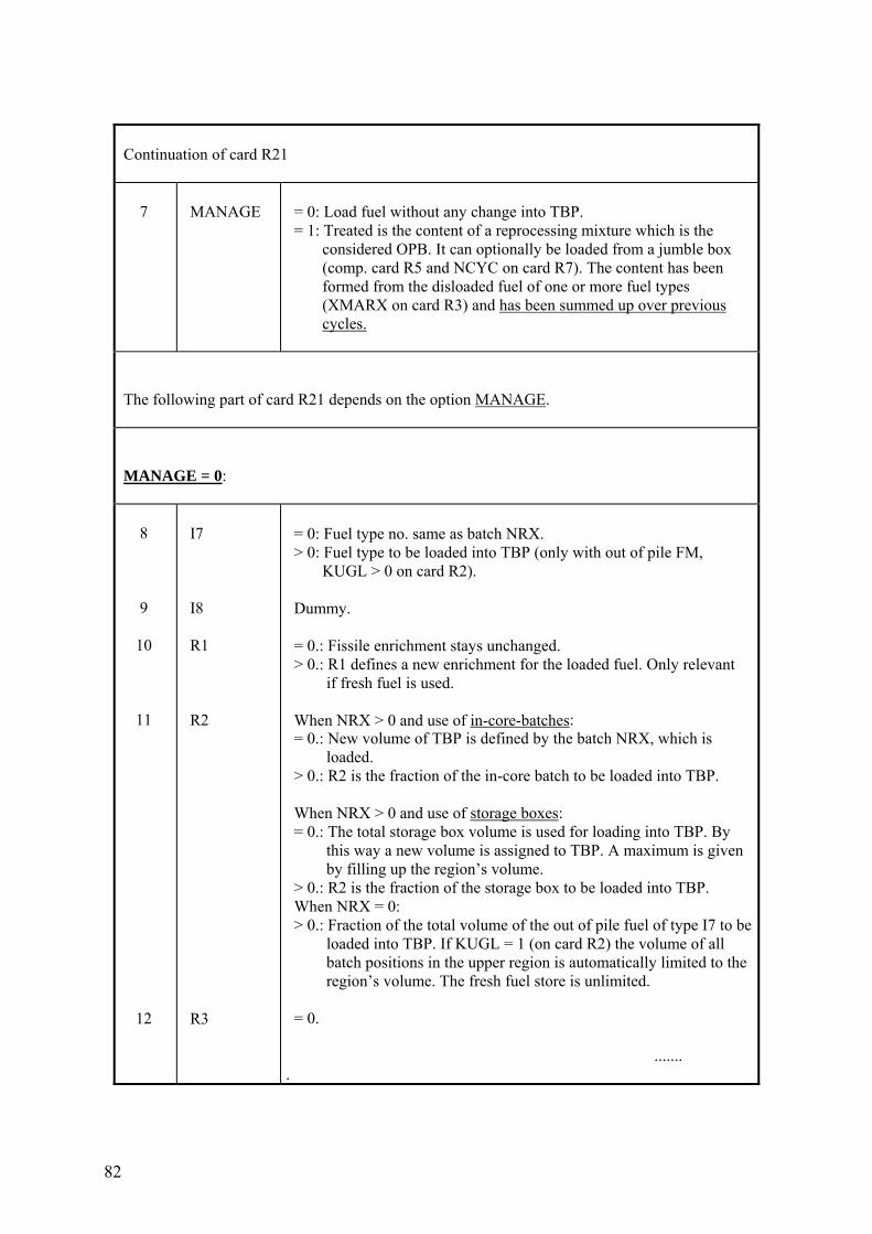
82
Continuation of card R21 7
MANAGE
= 0: Load fuel without any change into TBP. = 1: Treated is the content of a reprocessing mixture which is the considered OPB. It can optionally be loaded from a jumble box (comp. card R5 and NCYC on card R7). The content has been formed from the disloaded fuel of one or more fuel types (XMARX on card R3) and has been summed up over previous cycles.
The following part of card R21 depends on the option MANAGE. MANAGE = 0: 8 9 10 11 12
I7 I8 R1 R2 R3
= 0: Fuel type no. same as batch NRX. > 0: Fuel type to be loaded into TBP (only with out of pile FM, KUGL > 0 on card R2). Dummy. = 0.: Fissile enrichment stays unchanged. > 0.: R1 defines a new enrichment for the loaded fuel. Only relevant if fresh fuel is used. When NRX > 0 and use of in-core-batches: = 0.: New volume of TBP is defined by the batch NRX, which is loaded. > 0.: R2 is the fraction of the in-core batch to be loaded into TBP. When NRX > 0 and use of storage boxes: = 0.: The total storage box volume is used for loading into TBP. By this way a new volume is assigned to TBP. A maximum is given by filling up the region’s volume. > 0.: R2 is the fraction of the storage box to be loaded into TBP. When NRX = 0: > 0.: Fraction of the total volume of the out of pile fuel of type I7 to be loaded into TBP. If KUGL = 1 (on card R2) the volume of all batch positions in the upper region is automatically limited to the region’s volume. The fresh fuel store is unlimited. = 0. ....... .
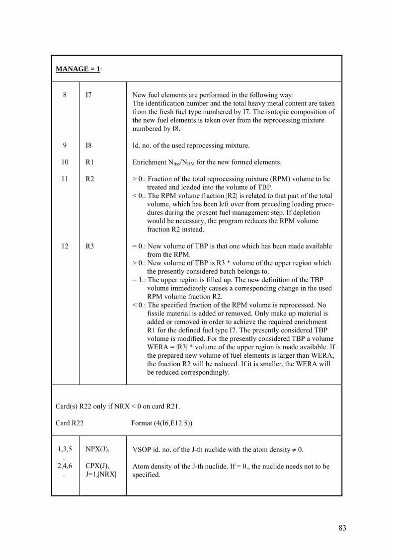
83
MANAGE = 1: 8 9 10 11 12
I7 I8 R1 R2 R3
New fuel elements are performed in the following way: The identification number and the total heavy metal content are taken from the fresh fuel type numbered by I7. The isotopic composition of the new fuel elements is taken over from the reprocessing mixture numbered by I8. Id. no. of the used reprocessing mixture. Enrichment Nfiss/NHM for the new formed elements. > 0.: Fraction of the total reprocessing mixture (RPM) volume to be treated and loaded into the volume of TBP. < 0.: The RPM volume fraction |R2| is related to that part of the total volume, which has been left over from preceding loading proce- dures during the present fuel management step. If depletion would be necessary, the program reduces the RPM volume fraction R2 instead. = 0.: New volume of TBP is that one which has been made available from the RPM. > 0.: New volume of TBP is R3 * volume of the upper region which the presently considered batch belongs to. = 1.: The upper region is filled up. The new definition of the TBP volume immediately causes a corresponding change in the used RPM volume fraction R2. < 0.: The specified fraction of the RPM volume is reprocessed. No fissile material is added or removed. Only make up material is added or removed in order to achieve the required enrichment R1 for the defined fuel type I7. The presently considered TBP volume is modified. For the presently considered TBP a volume WERA = |R3| * volume of the upper region is made available. If the prepared new volume of fuel elements is larger than WERA, the fraction R2 will be reduced. If it is smaller, the WERA will be reduced correspondingly.
Card(s) R22 only if NRX < 0 on card R21. Card R22 Format (4(I6,E12.5)) 1,3,5 . 2,4,6 .
NPX(J), CPX(J), J=1,|NRX|
VSOP id. no. of the J-th nuclide with the atom density ≠ 0. Atom density of the J-th nuclide. If = 0., the nuclide needs not to be specified.
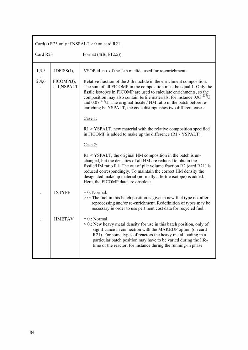
84
Card(s) R23 only if NSPALT > 0 on card R21. Card R23 Format (4(I6,E12.5)) 1,3,5 . 2,4,6 . . .
IDFISS(J), FICOMP(J), J=1,NSPALT IXTYPE HMETAV
VSOP id. no. of the J-th nuclide used for re-enrichment. Relative fraction of the J-th nuclide in the enrichment composition. The sum of all FICOMP in the composition must be equal 1. Only the fissile isotopes in FICOMP are used to calculate enrichments, so the composition may also contain fertile materials, for instance 0.93 235U and 0.07 238U. The original fissile / HM ratio in the batch before re- enriching be YSPALT, the code distinguishes two different cases: Case 1: R1 > YSPALT, new material with the relative composition specified in FICOMP is added to make up the difference (R1 - YSPALT). Case 2: R1 < YSPALT, the original HM composition in the batch is un- changed, but the densities of all HM are reduced to obtain the fissile/HM ratio R1. The out of pile volume fraction R2 (card R21) is reduced correspondingly. To maintain the correct HM density the designated make up material (normally a fertile isotope) is added. Here, the FICOMP data are obsolete. = 0: Normal. > 0: The fuel in this batch position is given a new fuel type no. after reprocessing and/or re-enrichment. Redefinition of types may be necessary in order to use pertinent cost data for recycled fuel. = 0.: Normal. > 0.: New heavy metal density for use in this batch position, only of significance in connection with the MAKEUP option (on card R21). For some types of reactors the heavy metal loading in a particular batch position may have to be varied during the life- time of the reactor, for instance during the running-in phase.
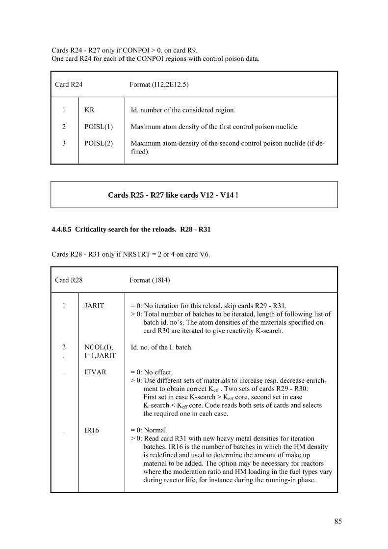
85
Cards R24 - R27 only if CONPOI > 0. on card R9. One card R24 for each of the CONPOI regions with control poison data.
Card R24 Format (I12,2E12.5) 1 2 3
KR POISL(1) POISL(2)
Id. number of the considered region. Maximum atom density of the first control poison nuclide. Maximum atom density of the second control poison nuclide (if de- fined).
Cards R25 - R27 like cards V12 - V14 !
4.4.8.5 Criticality search for the reloads. R28 - R31 Cards R28 - R31 only if NRSTRT = 2 or 4 on card V6.
Card R28 Format (18I4) 1 2 . . .
JARIT NCOL(I), I=1,JARIT ITVAR IR16
= 0: No iteration for this reload, skip cards R29 - R31. > 0: Total number of batches to be iterated, length of following list of batch id. no’s. The atom densities of the materials specified on card R30 are iterated to give reactivity K-search. Id. no. of the I. batch. = 0: No effect. > 0: Use different sets of materials to increase resp. decrease enrich- ment to obtain correct Keff . Two sets of cards R29 - R30: First set in case K-search > Keff core, second set in case K-search < Keff core. Code reads both sets of cards and selects the required one in each case. = 0: Normal. > 0: Read card R31 with new heavy metal densities for iteration batches. IR16 is the number of batches in which the HM density is redefined and used to determine the amount of make up material to be added. The option may be necessary for reactors where the moderation ratio and HM loading in the fuel types vary during reactor life, for instance during the running-in phase.
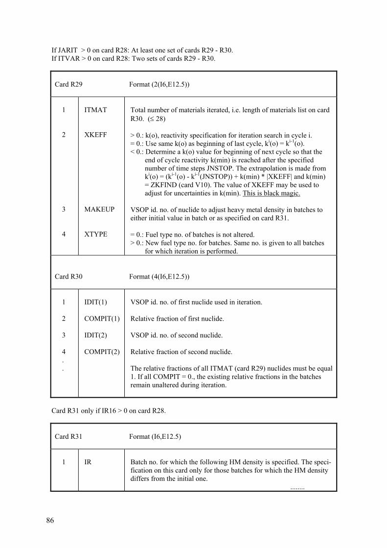
86
If JARIT > 0 on card R28: At least one set of cards R29 - R30. If ITVAR > 0 on card R28: Two sets of cards R29 - R30.
Card R29 Format (2(I6,E12.5)) 1 2 3 4
ITMAT XKEFF MAKEUP XTYPE
Total number of materials iterated, i.e. length of materials list on card R30. (≤ 28) > 0.: k(o), reactivity specification for iteration search in cycle i. = 0.: Use same k(o) as beginning of last cycle, ki(o) = ki-1(o). < 0.: Determine a k(o) value for beginning of next cycle so that the end of cycle reactivity k(min) is reached after the specified number of time steps JNSTOP. The extrapolation is made from ki(o) = (ki-1(o) - ki-1(JNSTOP)) + k(min) * |XKEFF| and k(min) = ZKFIND (card V10). The value of XKEFF may be used to adjust for uncertainties in k(min). This is black magic. VSOP id. no. of nuclide to adjust heavy metal density in batches to either initial value in batch or as specified on card R31. = 0.: Fuel type no. of batches is not altered. > 0.: New fuel type no. for batches. Same no. is given to all batches for which iteration is performed.
Card R30 Format (4(I6,E12.5)) 1 2 3 4 . .
IDIT(1) COMPIT(1) IDIT(2) COMPIT(2)
VSOP id. no. of first nuclide used in iteration. Relative fraction of first nuclide. VSOP id. no. of second nuclide. Relative fraction of second nuclide. The relative fractions of all ITMAT (card R29) nuclides must be equal 1. If all COMPIT = 0., the existing relative fractions in the batches remain unaltered during iteration.
Card R31 only if IR16 > 0 on card R28.
Card R31 Format (I6,E12.5) 1
IR
Batch no. for which the following HM density is specified. The speci- fication on this card only for those batches for which the HM density differs from the initial one. ........
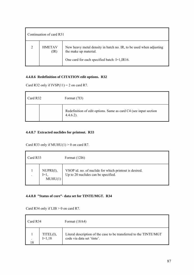
87
Continuation of card R31 2
HMETAV (IR)
New heavy metal density in batch no. IR, to be used when adjusting the make up material. One card for each specified batch: I=1,IR16.
4.4.8.6 Redefinition of CITATION edit options. R32 Card R32 only if IVSP(11) = 2 on card R7.
Card R32 Format (7I3)
Redefinition of edit options. Same as card C4 (see input section 4.4.6.2).
4.4.8.7 Extracted nuclides for printout. R33 Card R33 only if MUHU(1) > 0 on card R7.
Card R33 Format (12I6) 1 .
NUPRI(I), I=1, MUHU(1)
VSOP id. no. of nuclide for which printout is desired. Up to 20 nuclides can be specified.
4.4.8.8 ”Status of core”- data set for TINTE/MGT. R34 Card R34 only if LIB > 0 on card R7.
Card R34 Format (18A4) 1 . 18
TITEL(I), I=1,18
Literal description of the case to be transferred to the TINTE/MGT code via data set ‘tinte’.
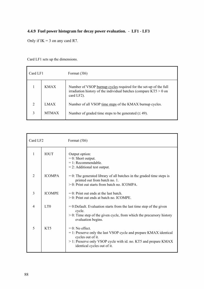
88
4.4.9 Fuel power histogram for decay power evaluation. - LF1 - LF3 Only if IK = 3 on any card R7. Card LF1 sets up the dimensions.
Card LF1 Format (3I6) 1 2 3
KMAX LMAX MTMAX
Number of VSOP burnup cycles required for the set-up of the full irradiation history of the individual batches (compare KT5 > 0 on card LF2). Number of all VSOP time steps of the KMAX burnup cycles. Number of graded time steps to be generated (≤ 49).
Card LF2 Format (5I6) 1 2 3 4 5
IOUT ICOMPA ICOMPE LT0 KT5
Output option: = 0: Short output. = 1: Recommendable. = 2: Additional test output. = 0: The generated library of all batches in the graded time steps is printed out from batch no. 1. > 0: Print out starts from batch no. ICOMPA. = 0: Print out ends at the last batch. > 0: Print out ends at batch no. ICOMPE. = 0:Default. Evaluation starts from the last time step of the given cycle. > 0: Time step of the given cycle, from which the precursory history evaluation begins. = 0: No effect. = 1: Preserve only the last VSOP cycle and prepare KMAX identical cycles out of it. > 1: Preserve only VSOP cycle with id. no. KT5 and prepare KMAX identical cycles out of it.
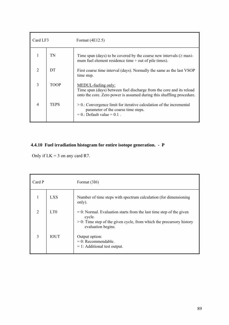
89
Card LF3 Format (4E12.5) 1 2 3 4
TN DT TOOP TEPS
Time span (days) to be covered by the coarse new intervals (≥ maxi- mum fuel element residence time + out of pile times). First coarse time interval (days). Normally the same as the last VSOP time step. MEDUL-fueling only: Time span (days) between fuel discharge from the core and its reload onto the core. Zero power is assumed during this shuffling procedure. > 0.: Convergence limit for iterative calculation of the incremental parameter of the coarse time steps. = 0.: Default value = 0.1 .
4.4.10 Fuel irradiation histogram for entire isotope generation. - P Only if LK = 3 on any card R7.
Card P Format (3I6) 1 2 3
LXS LT0 IOUT
Number of time steps with spectrum calculation (for dimensioning only). = 0: Normal. Evaluation starts from the last time step of the given cycle. > 0: Time step of the given cycle, from which the precursory history evaluation begins. Output option: = 0: Recommendable. = 1: Additional test output.
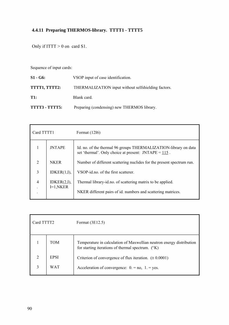
90
4.4.11 Preparing THERMOS-library. TTTT1 - TTTT5 Only if ITTT > 0 on card S1. Sequence of input cards: S1 - G6: VSOP input of case identification. TTTT1, TTTT2: THERMALIZATION input without selfshielding factors. T1: Blank card. TTTT3 - TTTT5: Preparing (condensing) new THERMOS library.
Card TTTT1 Format (12I6) 1 2 3 4 . .
JNTAPE NKER IDKER(1,I), IDKER(2,I), I=1,NKER
Id. no. of the thermal 96 groups THERMALIZATION-library on data set ‘thermal’. Only choice at present: JNTAPE = 115 . Number of different scattering nuclides for the present spectrum run. VSOP-id.no. of the first scatterer. Thermal library-id.no. of scattering matrix to be applied. NKER different pairs of id. numbers and scattering matrices.
Card TTTT2 Format (3E12.5) 1 2 3
TOM EPSI WAT
Temperature in calculation of Maxwellian neutron energy distribution for starting iterations of thermal spectrum. (°K) Criterion of convergence of flux iteration. (≅ 0.0001) Acceleration of convergence: 0. = no, 1. = yes.
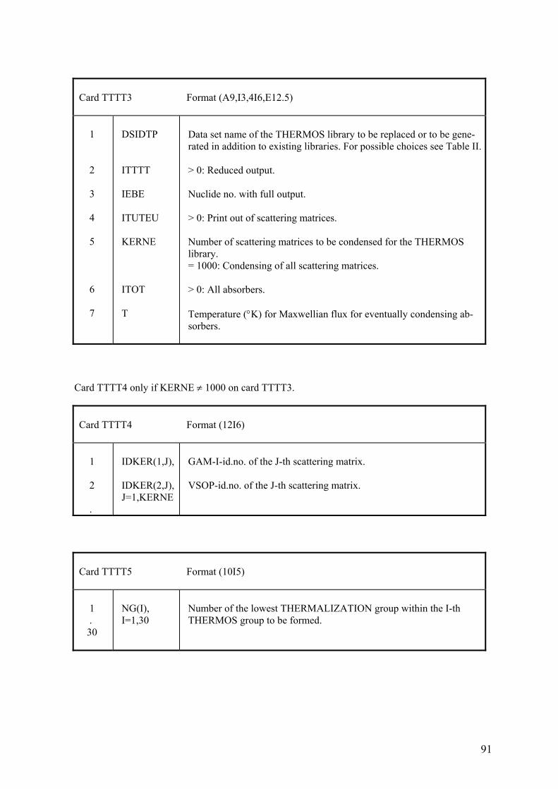
91
Card TTTT3 Format (A9,I3,4I6,E12.5) 1 2 3 4 5 6 7
DSIDTP ITTTT IEBE ITUTEU KERNE ITOT T
Data set name of the THERMOS library to be replaced or to be gene- rated in addition to existing libraries. For possible choices see Table II. > 0: Reduced output. Nuclide no. with full output. > 0: Print out of scattering matrices. Number of scattering matrices to be condensed for the THERMOS library. = 1000: Condensing of all scattering matrices. > 0: All absorbers. Temperature (°K) for Maxwellian flux for eventually condensing ab- sorbers.
Card TTTT4 only if KERNE ≠ 1000 on card TTTT3.
Card TTTT4 Format (12I6) 1 2 .
IDKER(1,J), IDKER(2,J), J=1,KERNE
GAM-I-id.no. of the J-th scattering matrix. VSOP-id.no. of the J-th scattering matrix.
Card TTTT5 Format (10I5) 1 . 30
NG(I), I=1,30
Number of the lowest THERMALIZATION group within the I-th THERMOS group to be formed.
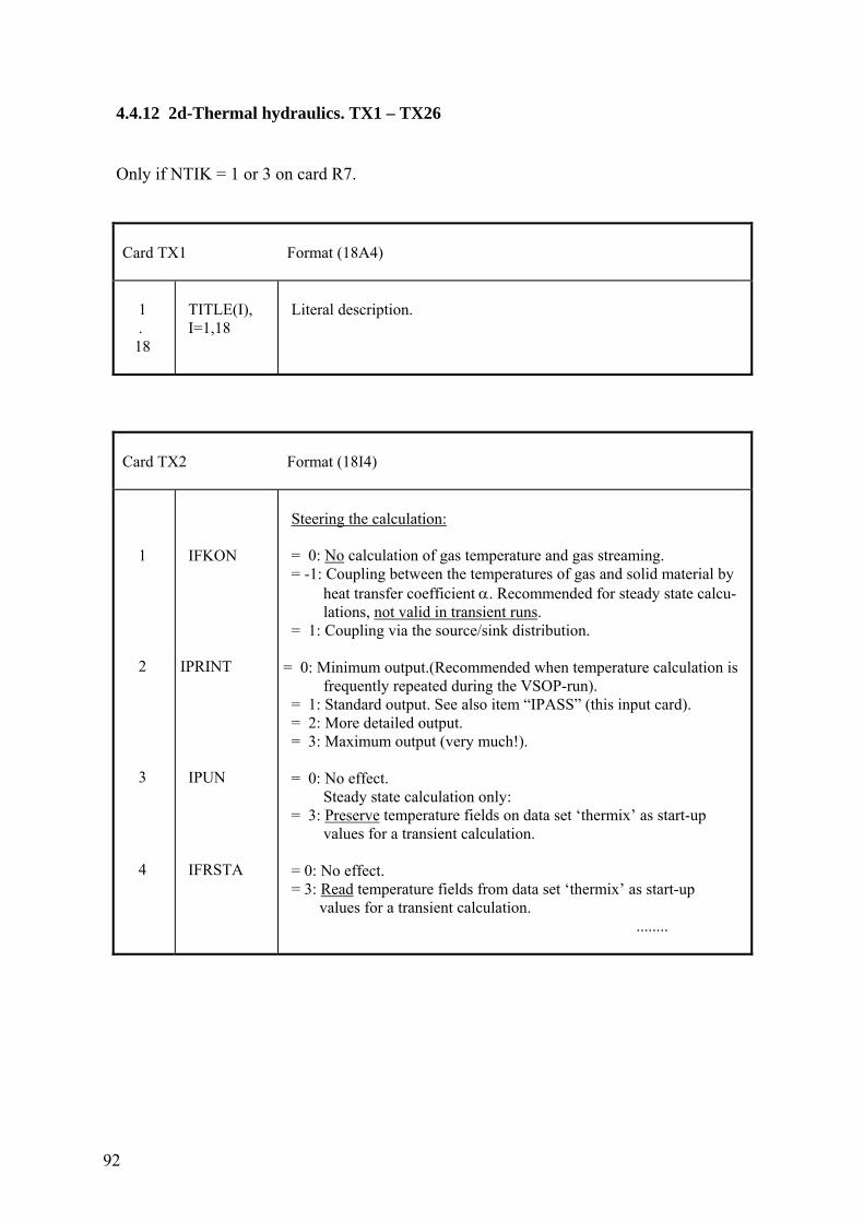
92
4.4.12 2d-Thermal hydraulics. TX1 – TX26 Only if NTIK = 1 or 3 on card R7.
Card TX1 Format (18A4) 1 . 18
TITLE(I), I=1,18
Literal description.
Card TX2 Format (18I4) 1 2 3 4
IFKON IPRINT IPUN IFRSTA
Steering the calculation: = 0: No calculation of gas temperature and gas streaming. = -1: Coupling between the temperatures of gas and solid material by heat transfer coefficient α. Recommended for steady state calcu- lations, not valid in transient runs. = 1: Coupling via the source/sink distribution. = 0: Minimum output.(Recommended when temperature calculation is frequently repeated during the VSOP-run). = 1: Standard output. See also item “IPASS” (this input card). = 2: More detailed output. = 3: Maximum output (very much!). = 0: No effect. Steady state calculation only: = 3: Preserve temperature fields on data set ‘thermix’ as start-up values for a transient calculation. = 0: No effect. = 3: Read temperature fields from data set ‘thermix’ as start-up values for a transient calculation. ........
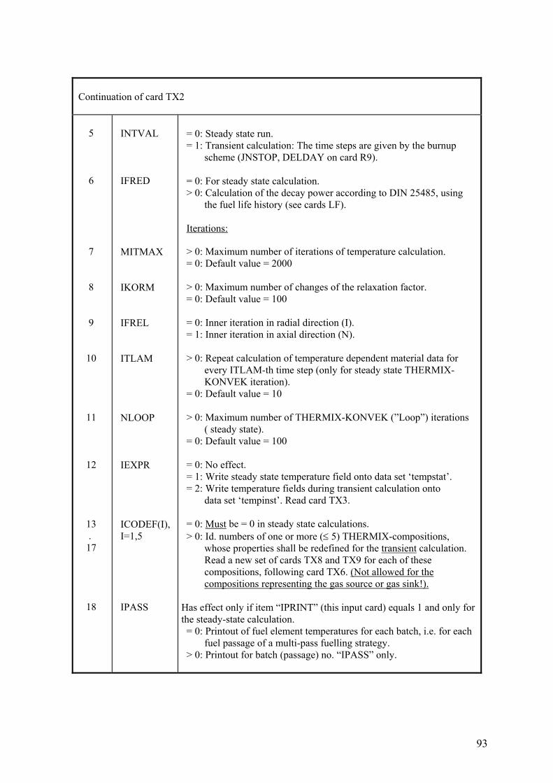
93
Continuation of card TX2 5 6 7 8 9 10 11 12 13 . 17 18
INTVAL IFRED MITMAX IKORM IFREL ITLAM NLOOP IEXPR ICODEF(I), I=1,5 IPASS
= 0: Steady state run. = 1: Transient calculation: The time steps are given by the burnup scheme (JNSTOP, DELDAY on card R9). = 0: For steady state calculation. > 0: Calculation of the decay power according to DIN 25485, using the fuel life history (see cards LF). Iterations: > 0: Maximum number of iterations of temperature calculation. = 0: Default value = 2000 > 0: Maximum number of changes of the relaxation factor. = 0: Default value = 100 = 0: Inner iteration in radial direction (I). = 1: Inner iteration in axial direction (N). > 0: Repeat calculation of temperature dependent material data for every ITLAM-th time step (only for steady state THERMIX- KONVEK iteration). = 0: Default value = 10 > 0: Maximum number of THERMIX-KONVEK (”Loop”) iterations ( steady state). = 0: Default value = 100 = 0: No effect. = 1: Write steady state temperature field onto data set ‘tempstat’. = 2: Write temperature fields during transient calculation onto data set ‘tempinst’. Read card TX3. = 0: Must be = 0 in steady state calculations. > 0: Id. numbers of one or more (≤ 5) THERMIX-compositions, whose properties shall be redefined for the transient calculation. Read a new set of cards TX8 and TX9 for each of these compositions, following card TX6. (Not allowed for the compositions representing the gas source or gas sink!). Has effect only if item “IPRINT” (this input card) equals 1 and only forthe steady-state calculation. = 0: Printout of fuel element temperatures for each batch, i.e. for each fuel passage of a multi-pass fuelling strategy. > 0: Printout for batch (passage) no. “IPASS” only.
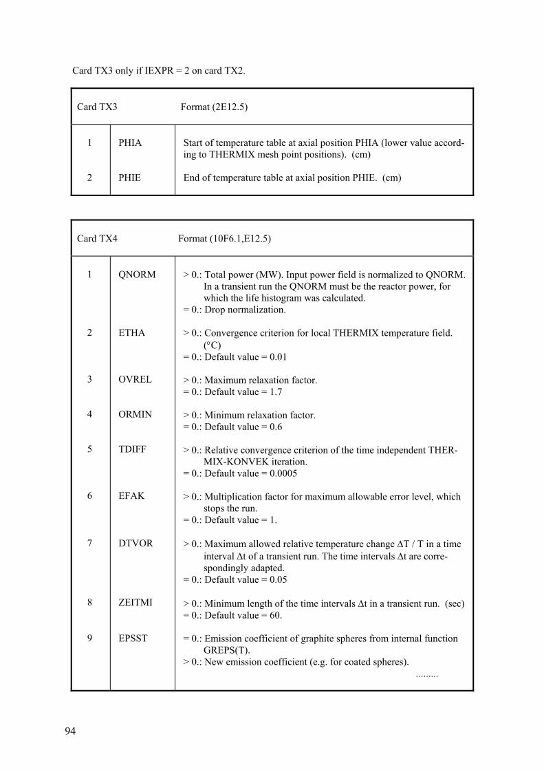
94
Card TX3 only if IEXPR = 2 on card TX2.
Card TX3 Format (2E12.5) 1 2
PHIA PHIE
Start of temperature table at axial position PHIA (lower value accord- ing to THERMIX mesh point positions). (cm) End of temperature table at axial position PHIE. (cm)
Card TX4 Format (10F6.1,E12.5) 1 2 3 4 5 6 7 8 9
QNORM ETHA OVREL ORMIN TDIFF EFAK DTVOR ZEITMI EPSST
> 0.: Total power (MW). Input power field is normalized to QNORM. In a transient run the QNORM must be the reactor power, for which the life histogram was calculated. = 0.: Drop normalization. > 0.: Convergence criterion for local THERMIX temperature field. (°C) = 0.: Default value = 0.01 > 0.: Maximum relaxation factor. = 0.: Default value = 1.7 > 0.: Minimum relaxation factor. = 0.: Default value = 0.6 > 0.: Relative convergence criterion of the time independent THER- MIX-KONVEK iteration. = 0.: Default value = 0.0005 > 0.: Multiplication factor for maximum allowable error level, which stops the run. = 0.: Default value = 1. > 0.: Maximum allowed relative temperature change ΔT / T in a time interval Δt of a transient run. The time intervals Δt are corre- spondingly adapted. = 0.: Default value = 0.05 > 0.: Minimum length of the time intervals Δt in a transient run. (sec) = 0.: Default value = 60. = 0.: Emission coefficient of graphite spheres from internal function GREPS(T). > 0.: New emission coefficient (e.g. for coated spheres). .........
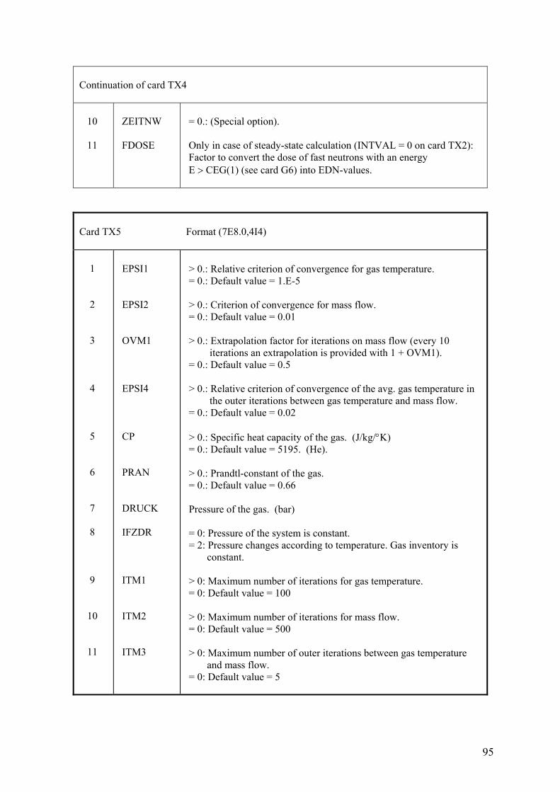
95
Continuation of card TX4 10 11
ZEITNW FDOSE
= 0.: (Special option). Only in case of steady-state calculation (INTVAL = 0 on card TX2): Factor to convert the dose of fast neutrons with an energy E > CEG(1) (see card G6) into EDN-values.
Card TX5 Format (7E8.0,4I4) 1 2 3 4 5 6 7 8 9 10 11
EPSI1 EPSI2 OVM1 EPSI4 CP PRAN DRUCK IFZDR ITM1 ITM2 ITM3
> 0.: Relative criterion of convergence for gas temperature. = 0.: Default value = 1.E-5 > 0.: Criterion of convergence for mass flow. = 0.: Default value = 0.01 > 0.: Extrapolation factor for iterations on mass flow (every 10 iterations an extrapolation is provided with 1 + OVM1). = 0.: Default value = 0.5 > 0.: Relative criterion of convergence of the avg. gas temperature in the outer iterations between gas temperature and mass flow. = 0.: Default value = 0.02 > 0.: Specific heat capacity of the gas. (J/kg/°K) = 0.: Default value = 5195. (He). > 0.: Prandtl-constant of the gas. = 0.: Default value = 0.66 Pressure of the gas. (bar) = 0: Pressure of the system is constant. = 2: Pressure changes according to temperature. Gas inventory is constant. > 0: Maximum number of iterations for gas temperature. = 0: Default value = 100 > 0: Maximum number of iterations for mass flow. = 0: Default value = 500 > 0: Maximum number of outer iterations between gas temperature and mass flow. = 0: Default value = 5
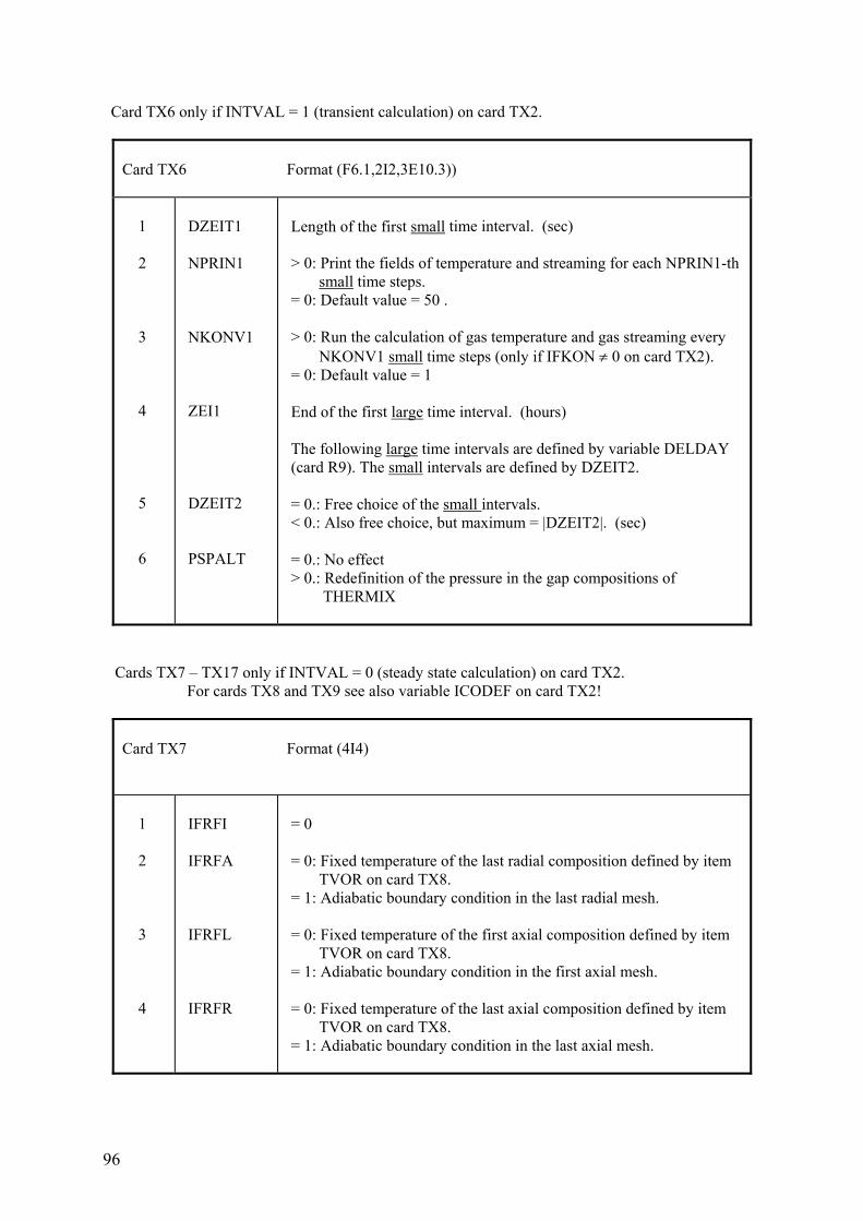
96
Card TX6 only if INTVAL = 1 (transient calculation) on card TX2.
Card TX6 Format (F6.1,2I2,3E10.3)) 1 2 3 4 5 6
DZEIT1 NPRIN1 NKONV1 ZEI1 DZEIT2 PSPALT
Length of the first small time interval. (sec) > 0: Print the fields of temperature and streaming for each NPRIN1-th small time steps. = 0: Default value = 50 . > 0: Run the calculation of gas temperature and gas streaming every NKONV1 small time steps (only if IFKON ≠ 0 on card TX2). = 0: Default value = 1 End of the first large time interval. (hours) The following large time intervals are defined by variable DELDAY (card R9). The small intervals are defined by DZEIT2. = 0.: Free choice of the small intervals. < 0.: Also free choice, but maximum = |DZEIT2|. (sec) = 0.: No effect > 0.: Redefinition of the pressure in the gap compositions of THERMIX
Cards TX7 – TX17 only if INTVAL = 0 (steady state calculation) on card TX2. For cards TX8 and TX9 see also variable ICODEF on card TX2!
Card TX7 Format (4I4) 1 2 3 4
IFRFI IFRFA IFRFL IFRFR
= 0 = 0: Fixed temperature of the last radial composition defined by item TVOR on card TX8. = 1: Adiabatic boundary condition in the last radial mesh. = 0: Fixed temperature of the first axial composition defined by item TVOR on card TX8. = 1: Adiabatic boundary condition in the first axial mesh. = 0: Fixed temperature of the last axial composition defined by item TVOR on card TX8. = 1: Adiabatic boundary condition in the last axial mesh.
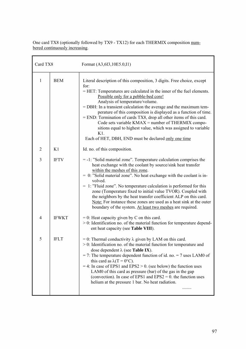
97
One card TX8 (optionally followed by TX9 - TX12) for each THERMIX composition num- bered continuously increasing.
Card TX8 Format (A3,6I3,10E5.0,I1) 1 2 3 4 5
BEM K1 IFTV IFWKT IFLT
Literal description of this composition, 3 digits. Free choice, except for: = HET: Temperatures are calculated in the inner of the fuel elements. Possible only for a pebble-bed core! Analysis of temperature/volume. = DBH: In a transient calculation the average and the maximum tem- perature of this composition is displayed as a function of time. = END: Termination of cards TX8, drop all other items of this card. Code sets variable KMAX = number of THERMIX compo- sitions equal to highest value, which was assigned to variable K1. Each of HET, DBH, END must be declared only one time Id. no. of this composition. = -1: ”Solid material zone”. Temperature calculation comprises the heat exchange with the coolant by source/sink heat transfer within the meshes of this zone. = 0: ”Solid material zone”. No heat exchange with the coolant is in- volved. = 1: ”Fluid zone”. No temperature calculation is performed for this zone (Temperature fixed to initial value TVOR). Coupled with the neighbors by the heat transfer coefficient ALP on this card. Note: For instance these zones are used as a heat sink at the outer boundary of the system. At least two meshes are required. = 0: Heat capacity given by C on this card. > 0: Identification no. of the material function for temperature depend- ent heat capacity (see Table VIII). = 0: Thermal conductivity λ given by LAM on this card. > 0: Identification no. of the material function for temperature and dose dependent λ (see Table IX). = 7: The temperature dependent function of id. no. = 7 uses LAM0 of this card as λ(T = 0°C). = 4: In case of EPS1 and EPS2 > 0. (see below) the function uses LAM0 of this card as pressure (bar) of the gas in the gap (convection). In case of EPS1 and EPS2 = 0. the function uses helium at the pressure 1 bar. No heat radiation. ........
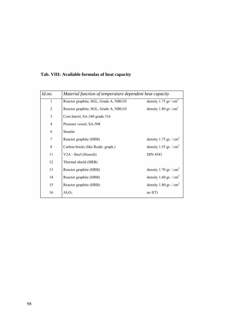
98
Tab. VIII: Available formulas of heat capacity
Id.no. Material function of temperature dependent heat capacity 1 Reactor graphite, SGL, Grade A, NBG10 density 1.75 gr / cm3
2 Reactor graphite, SGL, Grade A, NBG10 density 1.80 gr / cm3
3 Core barrel, SA-240 grade 316
4 Pressure vessel, SA-508
6 Steatite
7 Reactor graphite (HRB) density 1.75 gr. / cm3
8 Carbon bricks (like Reakt. graph.) density 1.55 gr. / cm3
11 V2A - Steel (Hoesch) DIN 4541
12 Thermal shield (HRB)
13 Reactor graphite (HRB) density 1.70 gr. / cm3
14 Reactor graphite (HRB) density 1.60 gr. / cm3
15 Reactor graphite (HRB) density 1.80 gr. / cm3
16 Al2O3 no f(T)
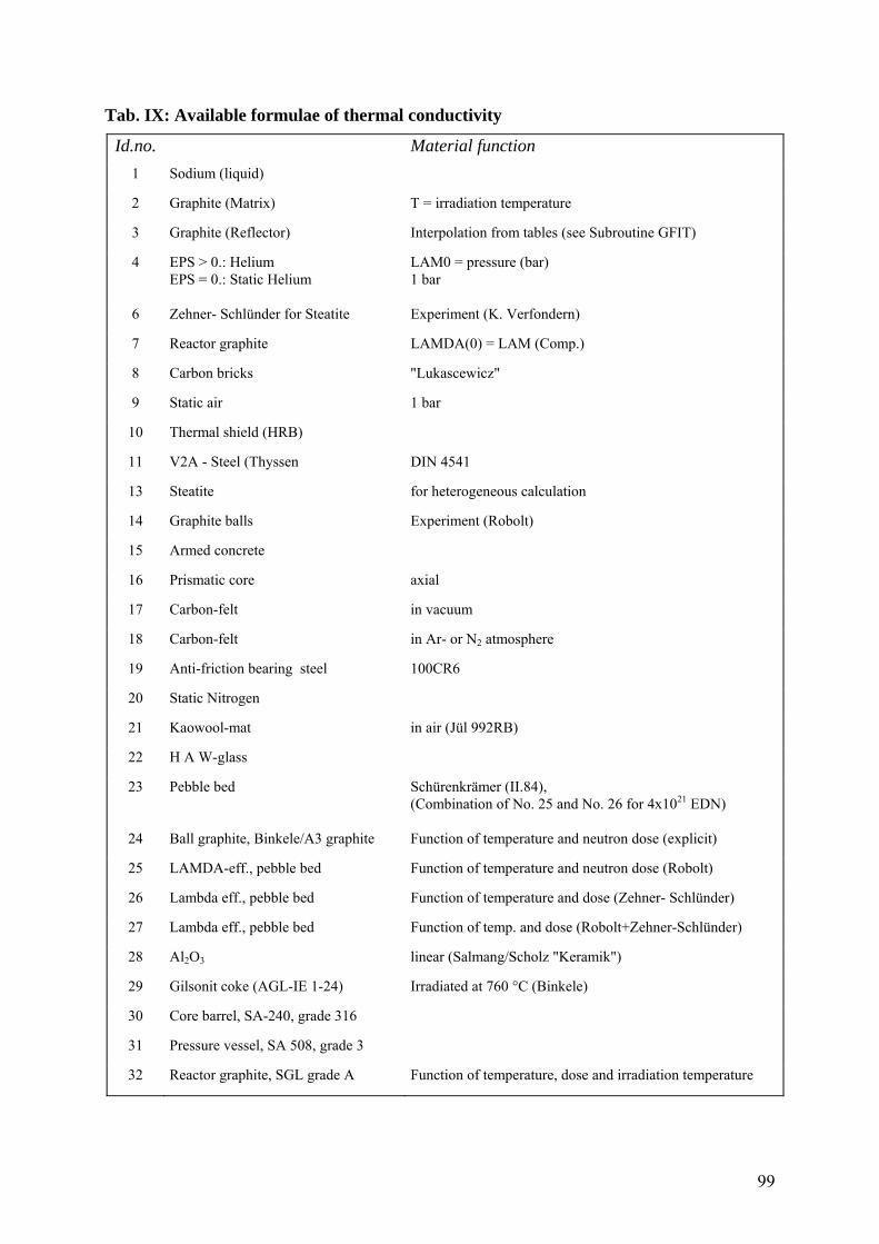
99
Tab. IX: Available formulae of thermal conductivity
Id.no. Material function 1 Sodium (liquid) 2 Graphite (Matrix) T = irradiation temperature
3 Graphite (Reflector) Interpolation from tables (see Subroutine GFIT)
4 EPS > 0.: Helium EPS = 0.: Static Helium
LAM0 = pressure (bar) 1 bar
6 Zehner- Schlünder for Steatite Experiment (K. Verfondern)
7 Reactor graphite LAMDA(0) = LAM (Comp.)
8 Carbon bricks "Lukascewicz"
9 Static air 1 bar
10 Thermal shield (HRB)
11 V2A - Steel (Thyssen DIN 4541
13 Steatite for heterogeneous calculation
14 Graphite balls Experiment (Robolt)
15 Armed concrete
16 Prismatic core axial
17 Carbon-felt in vacuum
18 Carbon-felt in Ar- or N2 atmosphere
19 Anti-friction bearing steel 100CR6
20 Static Nitrogen
21 Kaowool-mat in air (Jül 992RB)
22 H A W-glass
23 Pebble bed Schürenkrämer (II.84), (Combination of No. 25 and No. 26 for 4x10²¹ EDN)
24 Ball graphite, Binkele/A3 graphite Function of temperature and neutron dose (explicit)
25 LAMDA-eff., pebble bed Function of temperature and neutron dose (Robolt)
26 Lambda eff., pebble bed Function of temperature and dose (Zehner- Schlünder)
27 Lambda eff., pebble bed Function of temp. and dose (Robolt+Zehner-Schlünder)
28 Al2O3 linear (Salmang/Scholz "Keramik")
29 Gilsonit coke (AGL-IE 1-24) Irradiated at 760 °C (Binkele)
30 Core barrel, SA-240, grade 316
31 Pressure vessel, SA 508, grade 3
32 Reactor graphite, SGL grade A Function of temperature, dose and irradiation temperature
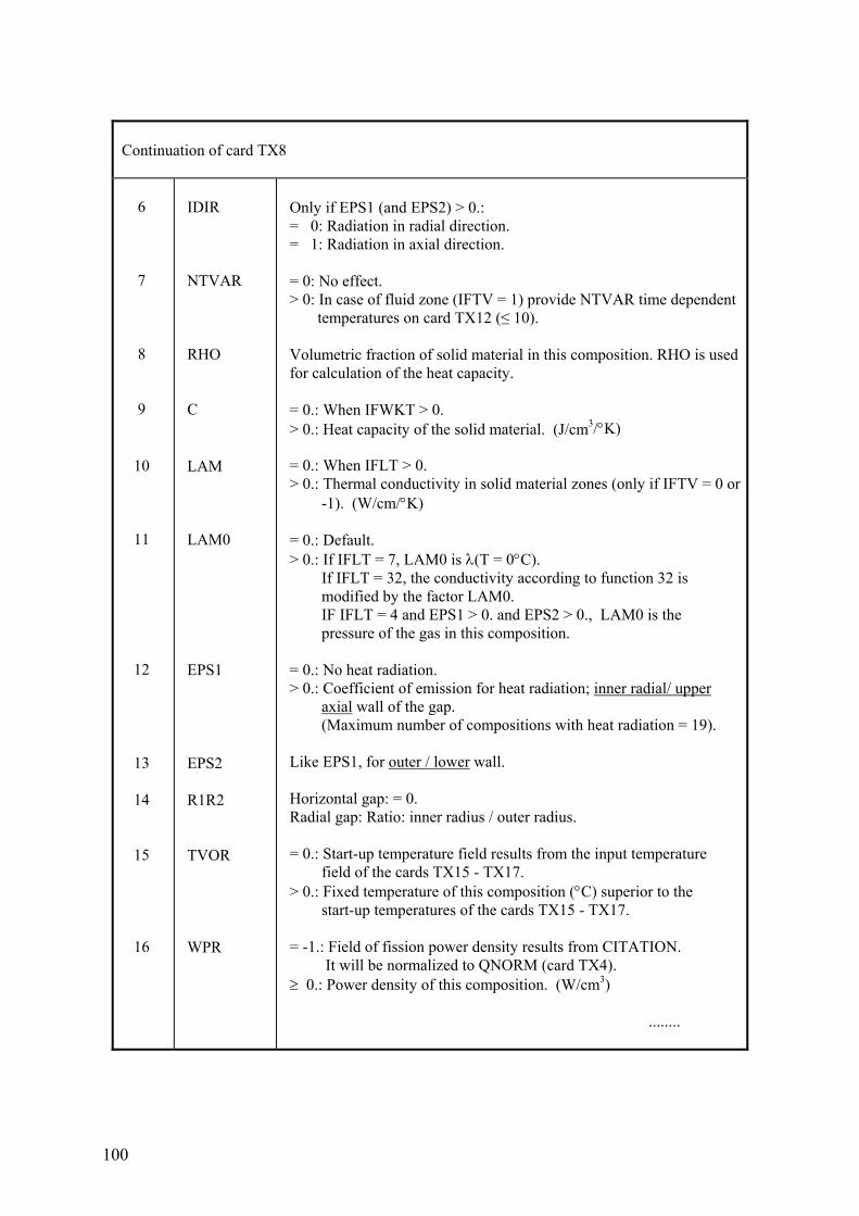
100
Continuation of card TX8 6 7 8 9 10 11 12 13 14 15 16
IDIR NTVAR RHO C LAM LAM0 EPS1 EPS2 R1R2 TVOR WPR
Only if EPS1 (and EPS2) > 0.: = 0: Radiation in radial direction. = 1: Radiation in axial direction. = 0: No effect. > 0: In case of fluid zone (IFTV = 1) provide NTVAR time dependent temperatures on card TX12 (≤ 10). Volumetric fraction of solid material in this composition. RHO is used for calculation of the heat capacity. = 0.: When IFWKT > 0. > 0.: Heat capacity of the solid material. (J/cm3/°K) = 0.: When IFLT > 0. > 0.: Thermal conductivity in solid material zones (only if IFTV = 0 or -1). (W/cm/°K) = 0.: Default. > 0.: If IFLT = 7, LAM0 is λ(T = 0°C). If IFLT = 32, the conductivity according to function 32 is modified by the factor LAM0. IF IFLT = 4 and EPS1 > 0. and EPS2 > 0., LAM0 is the pressure of the gas in this composition. = 0.: No heat radiation. > 0.: Coefficient of emission for heat radiation; inner radial/ upper axial wall of the gap. (Maximum number of compositions with heat radiation = 19). Like EPS1, for outer / lower wall. Horizontal gap: = 0. Radial gap: Ratio: inner radius / outer radius. = 0.: Start-up temperature field results from the input temperature field of the cards TX15 - TX17. > 0.: Fixed temperature of this composition (°C) superior to the start-up temperatures of the cards TX15 - TX17. = -1.: Field of fission power density results from CITATION. It will be normalized to QNORM (card TX4). ≥ 0.: Power density of this composition. (W/cm3) ........
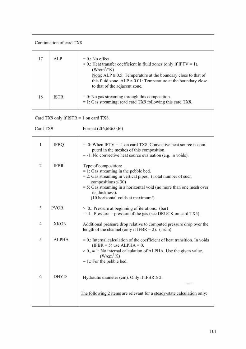
101
Continuation of card TX8 17 18
ALP ISTR
= 0.: No effect. > 0.: Heat transfer coefficient in fluid zones (only if IFTV = 1). (W/cm2/°K) Note: ALP ≅ 0.5: Temperature at the boundary close to that of this fluid zone. ALP ≅ 0.01: Temperature at the boundary close to that of the adjacent zone. = 0: No gas streaming through this composition. = 1: Gas streaming; read card TX9 following this card TX8.
Card TX9 only if ISTR = 1 on card TX8. Card TX9 Format (2I6,6E6.0,I6) 1 2 3 4 5 6
IFBQ IFBR PVOR XKON ALPHA DHYD
= 0: When IFTV = -1 on card TX8. Convective heat source is com- puted in the meshes of this composition. = -1: No convective heat source evaluation (e.g. in voids). Type of composition: = 1: Gas streaming in the pebble bed. = 2: Gas streaming in vertical pipes. (Total number of such compositions ≤ 30) = 5: Gas streaming in a horizontal void (no more than one mesh over its thickness). (10 horizontal voids at maximum!) > 0.: Pressure at beginning of iterations. (bar) = -1.: Pressure = pressure of the gas (see DRUCK on card TX5). Additional pressure drop relative to computed pressure drop over the length of the channel (only if IFBR = 2). (1/cm) = 0.: Internal calculation of the coefficient of heat transition. In voids (IFBR = 5) use ALPHA = 0. > 0., ≠ 1: No internal calculation of ALPHA. Use the given value. (W/cm2 K) = 1.: For the pebble bed. Hydraulic diameter (cm). Only if IFBR ≥ 2. ........ The following 2 items are relevant for a steady-state calculation only:
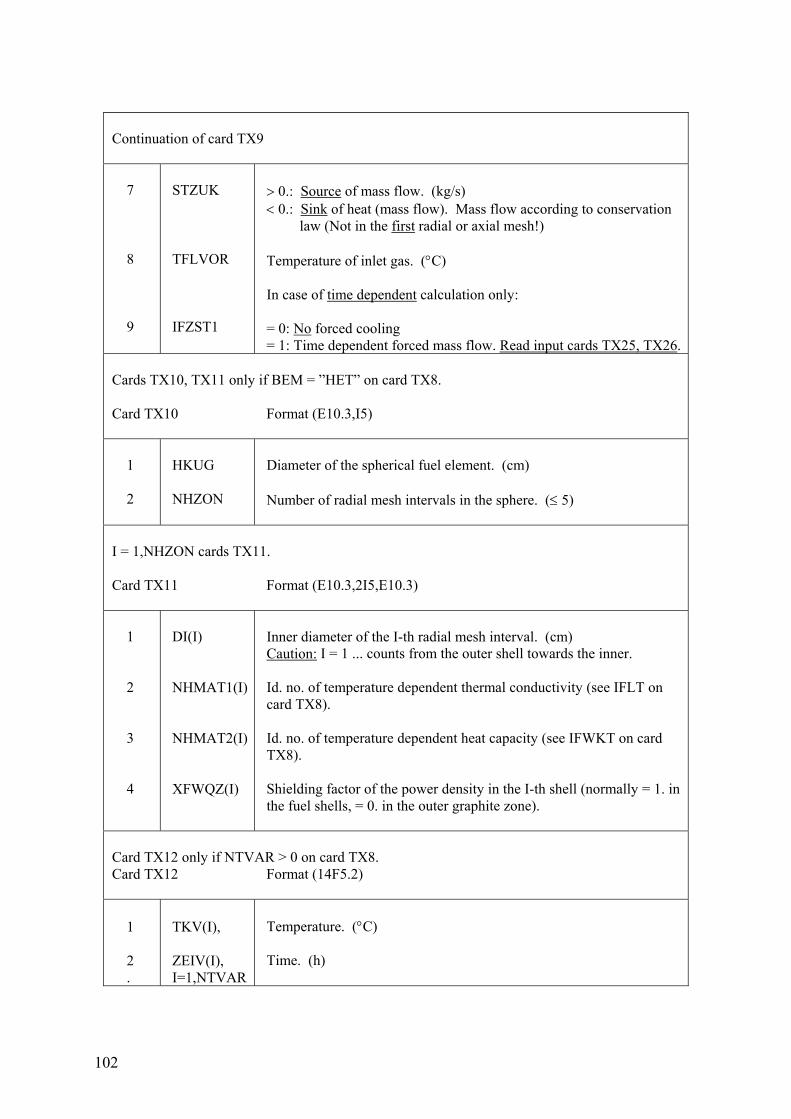
102
Continuation of card TX9 7 8 9
STZUK TFLVOR IFZST1
> 0.: Source of mass flow. (kg/s) < 0.: Sink of heat (mass flow). Mass flow according to conservation law (Not in the first radial or axial mesh!) Temperature of inlet gas. (°C) In case of time dependent calculation only: = 0: No forced cooling = 1: Time dependent forced mass flow. Read input cards TX25, TX26.
Cards TX10, TX11 only if BEM = ”HET” on card TX8. Card TX10 Format (E10.3,I5) 1 2
HKUG NHZON
Diameter of the spherical fuel element. (cm) Number of radial mesh intervals in the sphere. (≤ 5)
I = 1,NHZON cards TX11. Card TX11 Format (E10.3,2I5,E10.3) 1 2 3 4
DI(I) NHMAT1(I) NHMAT2(I) XFWQZ(I)
Inner diameter of the I-th radial mesh interval. (cm) Caution: I = 1 ... counts from the outer shell towards the inner. Id. no. of temperature dependent thermal conductivity (see IFLT on card TX8). Id. no. of temperature dependent heat capacity (see IFWKT on card TX8). Shielding factor of the power density in the I-th shell (normally = 1. in the fuel shells, = 0. in the outer graphite zone).
Card TX12 only if NTVAR > 0 on card TX8. Card TX12 Format (14F5.2) 1 2 .
TKV(I), ZEIV(I), I=1,NTVAR
Temperature. (°C) Time. (h)
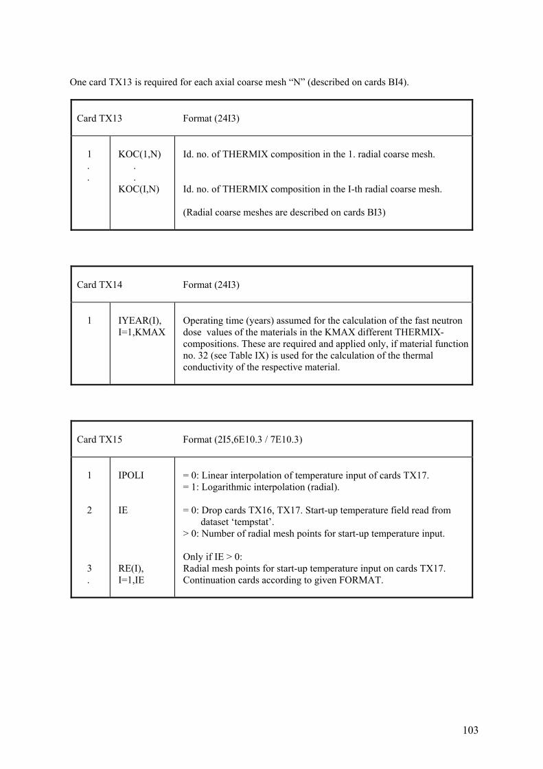
103
One card TX13 is required for each axial coarse mesh “N” (described on cards BI4).
Card TX13 Format (24I3) 1 . .
KOC(1,N) . . KOC(I,N)
Id. no. of THERMIX composition in the 1. radial coarse mesh. Id. no. of THERMIX composition in the I-th radial coarse mesh. (Radial coarse meshes are described on cards BI3)
Card TX14 Format (24I3) 1
IYEAR(I), I=1,KMAX
Operating time (years) assumed for the calculation of the fast neutron dose values of the materials in the KMAX different THERMIX- compositions. These are required and applied only, if material function no. 32 (see Table IX) is used for the calculation of the thermal conductivity of the respective material.
Card TX15 Format (2I5,6E10.3 / 7E10.3) 1 2 3 .
IPOLI IE RE(I), I=1,IE
= 0: Linear interpolation of temperature input of cards TX17. = 1: Logarithmic interpolation (radial). = 0: Drop cards TX16, TX17. Start-up temperature field read from dataset ‘tempstat’. > 0: Number of radial mesh points for start-up temperature input. Only if IE > 0: Radial mesh points for start-up temperature input on cards TX17. Continuation cards according to given FORMAT.
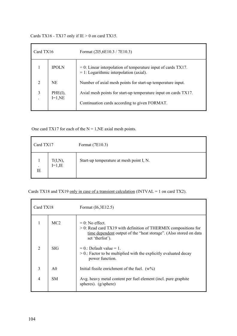
104
Cards TX16 - TX17 only if IE > 0 on card TX15.
Card TX16 Format (2I5,6E10.3 / 7E10.3) 1 2 3 .
IPOLN NE PHE(I), I=1,NE
= 0: Linear interpolation of temperature input of cards TX17. = 1: Logarithmic interpolation (axial). Number of axial mesh points for start-up temperature input. Axial mesh points for start-up temperature input on cards TX17. Continuation cards according to given FORMAT.
One card TX17 for each of the N = 1,NE axial mesh points.
Card TX17 Format (7E10.3) 1 . IE
T(I,N), I=1,IE
Start-up temperature at mesh point I, N.
Cards TX18 and TX19 only in case of a transient calculation (INTVAL = 1 on card TX2).
Card TX18 Format (I6,3E12.5) 1 2 3 4
MC2 SIG A0 SM
= 0: No effect. > 0: Read card TX19 with definition of THERMIX compositions for time dependent output of the “heat storage”. (Also stored on data set ‘therlist’). = 0.: Default value = 1. > 0.: Factor to be multiplied with the explicitly evaluated decay power function. Initial fissile enrichment of the fuel. (w%) Avg. heavy metal content per fuel element (incl. pure graphite spheres). (g/sphere)
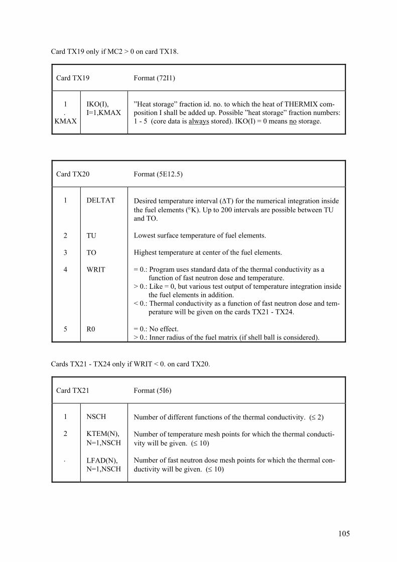
105
Card TX19 only if MC2 > 0 on card TX18.
Card TX19 Format (72I1) 1 . KMAX
IKO(I), I=1,KMAX
”Heat storage” fraction id. no. to which the heat of THERMIX com- position I shall be added up. Possible ”heat storage” fraction numbers: 1 - 5 (core data is always stored). IKO(I) = 0 means no storage.
Card TX20 Format (5E12.5) 1 2 3 4 5
DELTAT TU TO WRIT R0
Desired temperature interval (ΔT) for the numerical integration inside the fuel elements (°K). Up to 200 intervals are possible between TU and TO. Lowest surface temperature of fuel elements. Highest temperature at center of the fuel elements. = 0.: Program uses standard data of the thermal conductivity as a function of fast neutron dose and temperature. > 0.: Like = 0, but various test output of temperature integration inside the fuel elements in addition. < 0.: Thermal conductivity as a function of fast neutron dose and tem- perature will be given on the cards TX21 - TX24. = 0.: No effect. > 0.: Inner radius of the fuel matrix (if shell ball is considered).
Cards TX21 - TX24 only if WRIT < 0. on card TX20.
Card TX21 Format (5I6) 1 2 .
NSCH KTEM(N), N=1,NSCH LFAD(N), N=1,NSCH
Number of different functions of the thermal conductivity. (≤ 2) Number of temperature mesh points for which the thermal conducti- vity will be given. (≤ 10) Number of fast neutron dose mesh points for which the thermal con- ductivity will be given. (≤ 10)
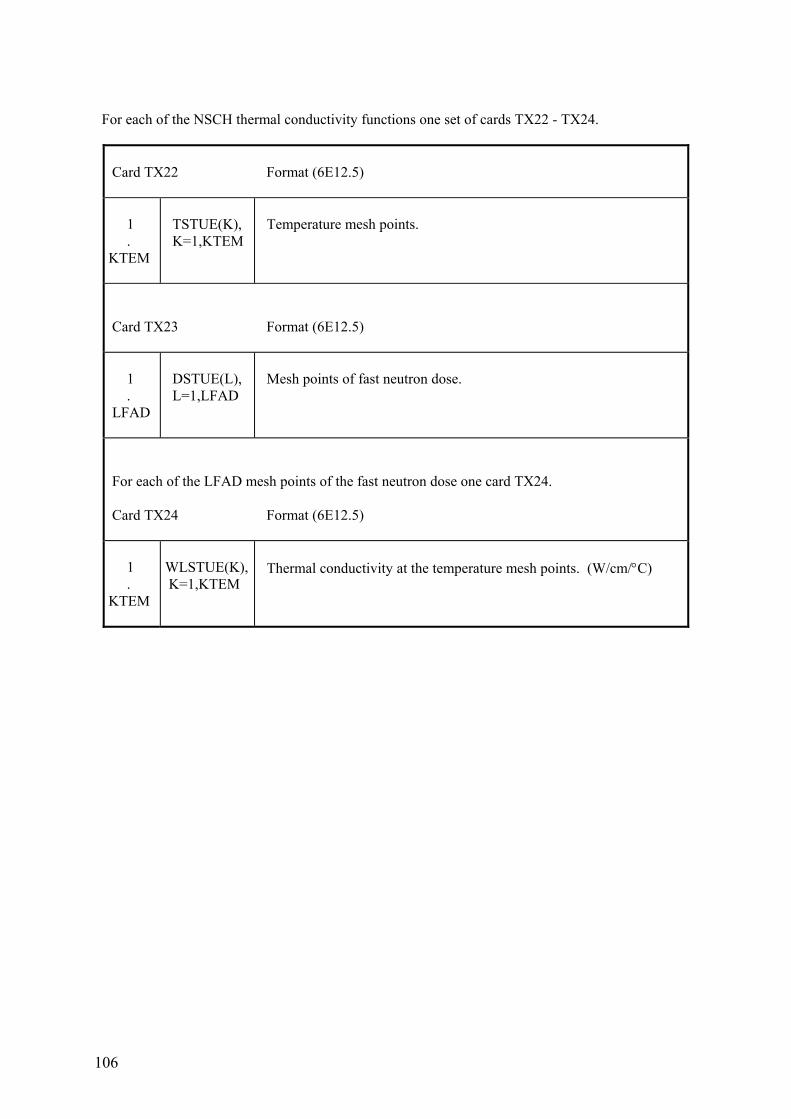
106
For each of the NSCH thermal conductivity functions one set of cards TX22 - TX24.
Card TX22 Format (6E12.5) 1 . KTEM
TSTUE(K), K=1,KTEM
Temperature mesh points.
Card TX23 Format (6E12.5) 1 . LFAD
DSTUE(L), L=1,LFAD
Mesh points of fast neutron dose.
For each of the LFAD mesh points of the fast neutron dose one card TX24. Card TX24 Format (6E12.5) 1 . KTEM
WLSTUE(K), K=1,KTEM
Thermal conductivity at the temperature mesh points. (W/cm/°C)
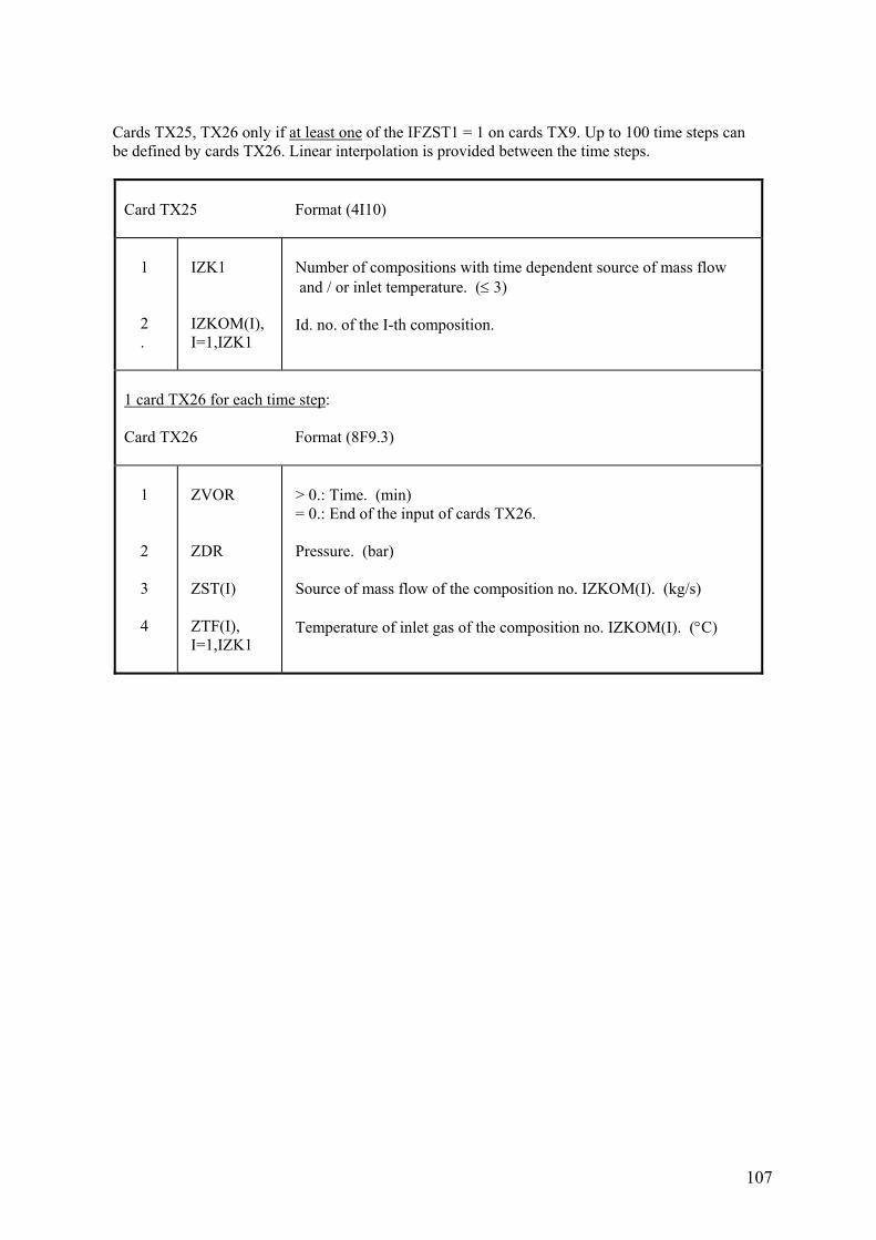
107
Cards TX25, TX26 only if at least one of the IFZST1 = 1 on cards TX9. Up to 100 time steps can be defined by cards TX26. Linear interpolation is provided between the time steps.
Card TX25 Format (4I10) 1 2 .
IZK1 IZKOM(I), I=1,IZK1
Number of compositions with time dependent source of mass flow and / or inlet temperature. (≤ 3) Id. no. of the I-th composition.
1 card TX26 for each time step: Card TX26 Format (8F9.3) 1 2 3 4
ZVOR ZDR ZST(I) ZTF(I), I=1,IZK1
> 0.: Time. (min) = 0.: End of the input of cards TX26. Pressure. (bar) Source of mass flow of the composition no. IZKOM(I). (kg/s) Temperature of inlet gas of the composition no. IZKOM(I). (°C)
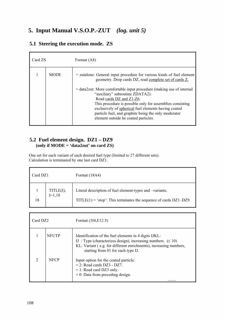
108
5. Input Manual V.S.O.P.-ZUT (log. unit 5) 5.1 Steering the execution mode. ZS
Card ZS Format (A8) 1
MODE
= zutalone: General input procedure for various kinds of fuel element geometry. Drop cards DZ, read complete set of cards Z. = data2zut: More comfortable input procedure (making use of internal “auxiliary” subroutine ZDATA2): Read cards DZ and Z1-Z6. This procedure is possible only for assemblies consisting exclusively of spherical fuel elements having coated particle fuel, and graphite being the only moderator element outside he coated particles.
5.2 Fuel element design. DZ1 – DZ9 (only if MODE = ‘data2zut’ on card ZS) One set for each variant of each desired fuel type (limited to 27 different sets). Calculation is terminated by one last card DZ1.
Card DZ1 Format (18A4) 1 . 18
TITLE(I), I=1,18
Literal description of fuel element-types and –variants. TITLE(1) = ‘stop’: This terminates the sequence of cards DZ1–DZ9.
Card DZ2 Format (3I4,E12.5) 1 2
NFUTP NFCP
Identification of the fuel elements in 4 digits IJKL: IJ : Type (characterizes design), increasing numbers. (≤ 10) KL: Variant ( e.g. for different enrichments), increasing numbers, starting from 01 for each type IJ. Input option for the coated particle: = 2: Read cards DZ3 - DZ7. = 1: Read card DZ3 only. = 0: Data from preceding design. ........
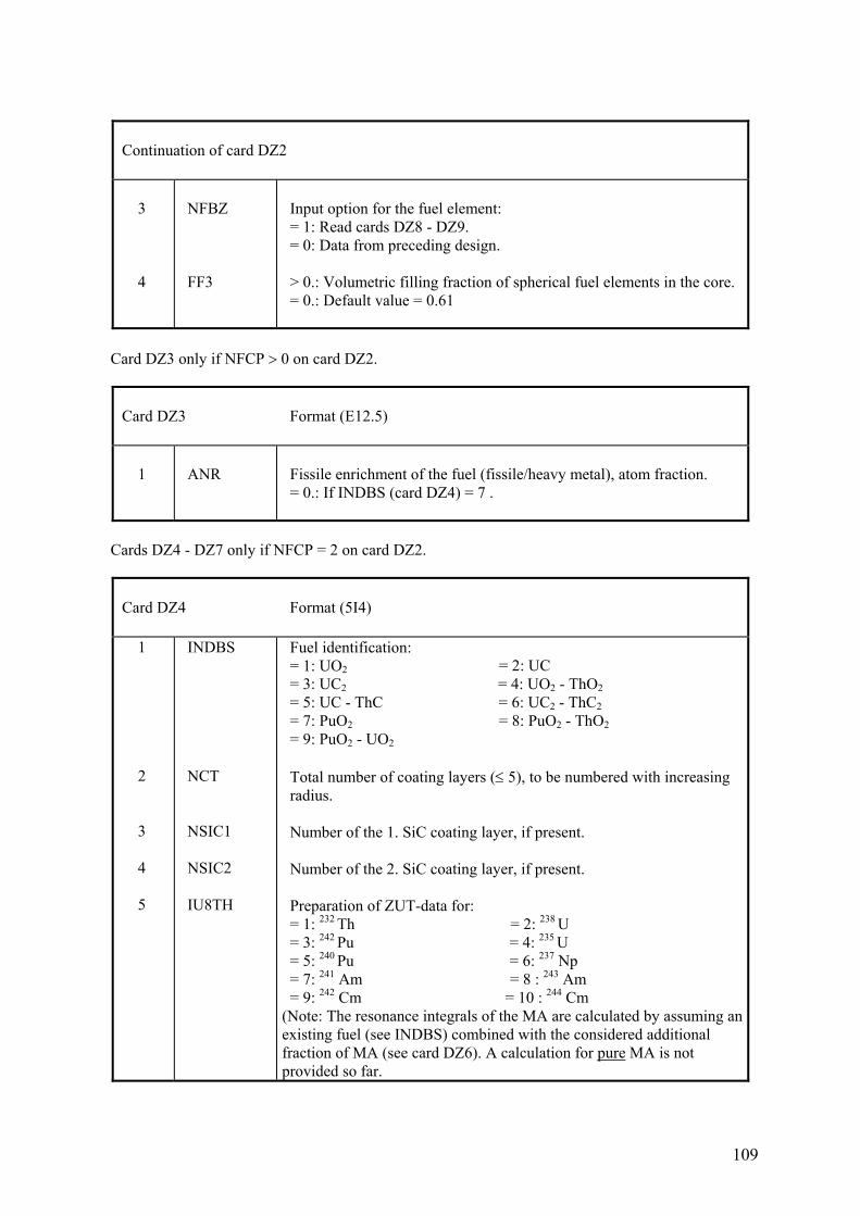
109
Continuation of card DZ2 3 4
NFBZ FF3
Input option for the fuel element: = 1: Read cards DZ8 - DZ9. = 0: Data from preceding design. > 0.: Volumetric filling fraction of spherical fuel elements in the core. = 0.: Default value = 0.61
Card DZ3 only if NFCP > 0 on card DZ2.
Card DZ3 Format (E12.5) 1
ANR
Fissile enrichment of the fuel (fissile/heavy metal), atom fraction. = 0.: If INDBS (card DZ4) = 7 .
Cards DZ4 - DZ7 only if NFCP = 2 on card DZ2.
Card DZ4 Format (5I4) 1 2 3 4 5
INDBS NCT NSIC1 NSIC2 IU8TH
Fuel identification: = 1: UO2 = 2: UC = 3: UC2 = 4: UO2 - ThO2 = 5: UC - ThC = 6: UC2 - ThC2 = 7: PuO2 = 8: PuO2 - ThO2 = 9: PuO2 - UO2 Total number of coating layers (≤ 5), to be numbered with increasing radius. Number of the 1. SiC coating layer, if present. Number of the 2. SiC coating layer, if present. Preparation of ZUT-data for: = 1: 232 Th = 2: 238 U = 3: 242 Pu = 4: 235 U = 5: 240 Pu = 6: 237 Np = 7: 241 Am = 8 : 243 Am = 9: 242 Cm = 10 : 244 Cm (Note: The resonance integrals of the MA are calculated by assuming an existing fuel (see INDBS) combined with the considered additional fraction of MA (see card DZ6). A calculation for pure MA is not provided so far.
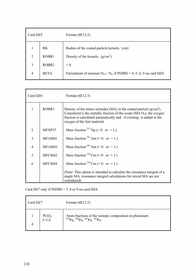
110
Card DZ5 Format (4E12.5) 1 2 3 4
RK ROBR1 ROBR2 BETA
Radius of the coated particle kernels. (cm) Density of the kernels. (g/cm3) = 0. Enrichment of uranium NU5 / NU if INDBS = 4, 5, 6, 9 on card DZ4.
Card DZ6 Format (6E12.5) 1 2 3 4 5 6
ROBR3 MFNP37 MFAM41 MFAM43 MFCM42 MFCM44
Density of the minor actinides (MA) in the coated particle (g/cm3). Considered is the metallic fraction of the oxide (MA O2), the oxygen fraction is calculated automatically and –if existing- is added to the oxygen of the fuel material. Mass fraction 237 Np (= 0. or = 1.) Mass fraction 241 Am (= 0. or = 1.) Mass fraction 243 Am (= 0. or = 1.) Mass fraction 242 Cm (= 0. or = 1.) Mass fraction 244 Cm (= 0. or = 1.) (Note: This option is intended to calculate the resonance integral of a single MA, resonance integral calculations for mixed MA are not considered)
Card DZ7 only if INDBS = 7, 8 or 9 on card DZ4.
Card DZ7 Format (4E12.5) 1 . 4
PU(I), I=1,4
Atom fractions of the isotopic composition in plutonium: 239Pu, 240Pu, 241Pu, 242Pu.
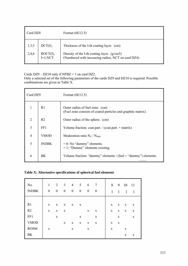
111
Card DZ8 Format (6E12.5) 1,3,5 2,4,6
DCT(I), ROCT(I), I=1,NCT
Thickness of the I-th coating layer. (cm) Density of the I-th coating layer. (g/cm3) (Numbered with increasing radius, NCT on card DZ4).
Cards DZ9 – DZ10 only if NFBZ = 1 on card DZ2. Only a selected set of the following parameters of the cards DZ9 and DZ10 is required. Possible combinations are given in Table X.
Card DZ9 Format (6E12.5) 1 2 3 4 5 6
R1 R2 FF1 VMOD INDBK BK
Outer radius of fuel zone. (cm) (Fuel zone consists of coated particles and graphite matrix). Outer radius of the sphere. (cm) Volume fraction: coat.part. / (coat.part. + matrix) Moderation ratio NC / NHM. = 0: No “dummy” elements. = 1: “Dummy” elements existing. Volume fraction: “dummy” elements / (fuel + “dummy”) elements. ........
Table X: Alternative specifications of spherical fuel elements
No.
INDBK
1 2 3 4 5 6 7
0 0 0 0 0 0 0
8 9 10 11
1 1 1 1
R1
R2
FF1
VMOD
ROSM
BK
x x x x x
x x x x x
x x x
x x x x x
x x x
x x x x
x x x x
x x
x x
x x
x x
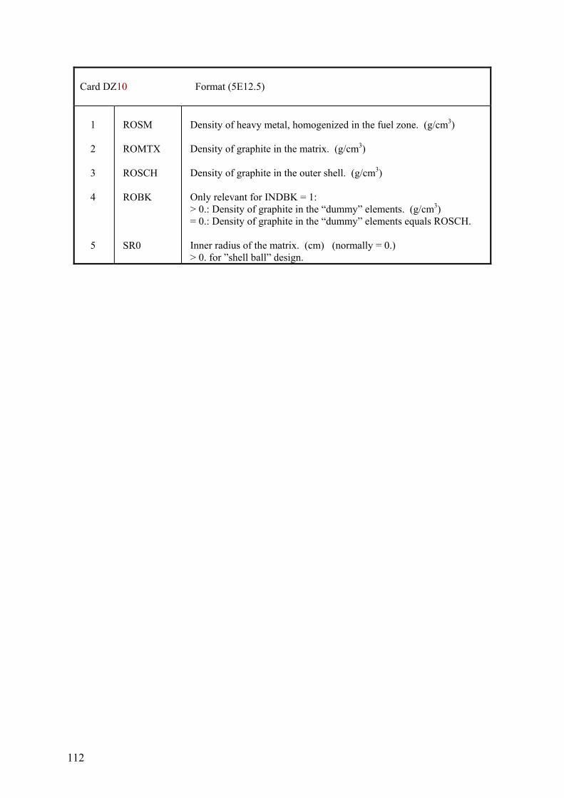
112
Card DZ10 Format (5E12.5) 1 2 3 4 5
ROSM ROMTX ROSCH ROBK SR0
Density of heavy metal, homogenized in the fuel zone. (g/cm3) Density of graphite in the matrix. (g/cm3) Density of graphite in the outer shell. (g/cm3) Only relevant for INDBK = 1: > 0.: Density of graphite in the “dummy” elements. (g/cm3) = 0.: Density of graphite in the “dummy” elements equals ROSCH. Inner radius of the matrix. (cm) (normally = 0.) > 0. for ”shell ball” design.
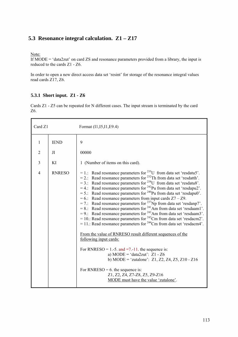
113
5.3 Resonance integral calculation. Z1 – Z17 Note: If MODE = ‘data2zut’ on card ZS and resonance parameters provided from a library, the input is reduced to the cards Z1 - Z6. In order to open a new direct access data set ‘resint’ for storage of the resonance integral values read cards Z17, Z6. 5.3.1 Short input. Z1 - Z6 Cards Z1 - Z5 can be repeated for N different cases. The input stream is terminated by the card Z6.
Card Z1 Format (I1,I5,I1,E9.4) 1 2 3 4
IEND JI KI RNRESO
9 00000 1 (Number of items on this card). = 1.: Read resonance parameters for 235U from data set ‘resdatu5’. = 2.: Read resonance parameters for 232Th from data set ‘resdatth’. = 3.: Read resonance parameters for 238U from data set ‘resdatu8’. = 4.: Read resonance parameters for 242Pu from data set ‘resdapu2’. = 5.: Read resonance parameters for 240Pu from data set ‘resdapu0’. = 6.: Read resonance parameters from input cards Z7 – Z9. = 7.: Read resonance parameters for 237Np from data set ‘resdanp7’. = 8.: Read resonance parameters for 241Am from data set ‘resdaam1’. = 9.: Read resonance parameters for 243Am from data set ‘resdaam3’. = 10.: Read resonance parameters for 242Cm from data set ‘resdacm2’. = 11.: Read resonance parameters for 244Cm from data set ‘resdacm4’. From the value of RNRESO result different sequences of the following input cards: For RNRESO = 1.-5. and =7.-11. the sequence is: a) MODE = ‘data2zut’: Z1 - Z6 b) MODE = ‘zutalone’: Z1, Z2, Z4, Z5, Z10 - Z16 For RNRESO = 6. the sequence is: Z1, Z2, Z4, Z7-Z8, Z5, Z9-Z16 MODE must have the value ‘zutalone’.
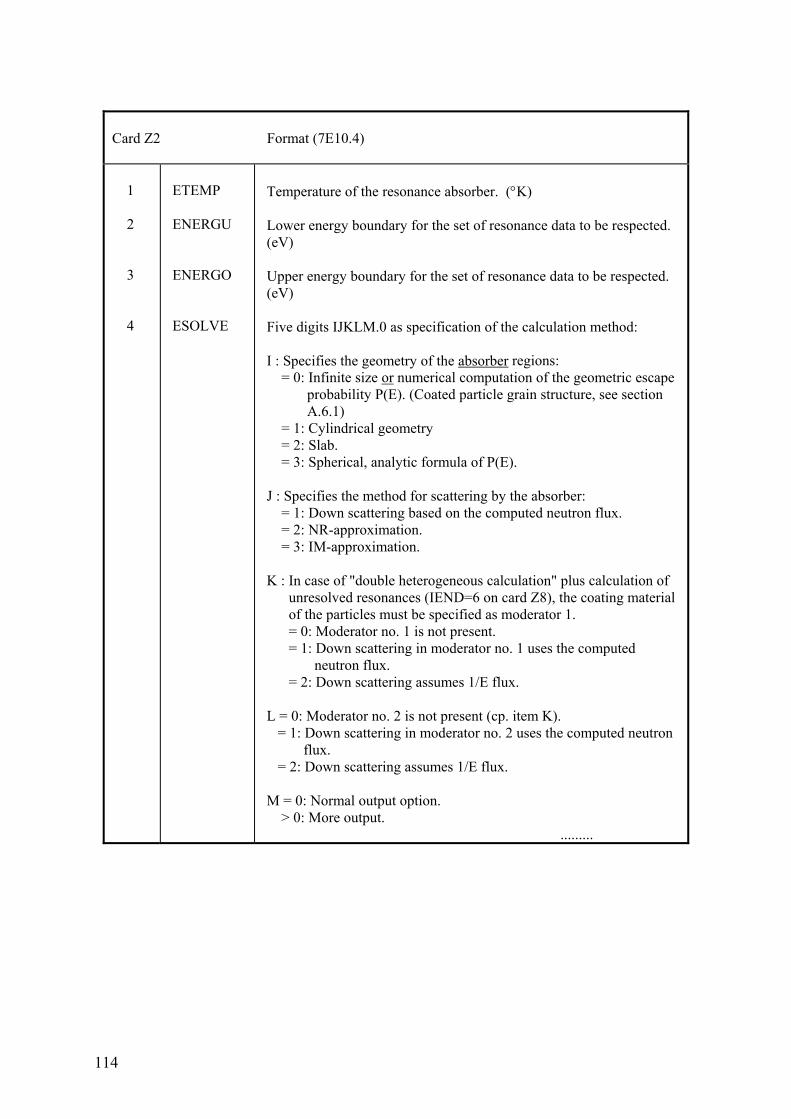
114
Card Z2 Format (7E10.4) 1 2 3 4
ETEMP ENERGU ENERGO ESOLVE
Temperature of the resonance absorber. (°K) Lower energy boundary for the set of resonance data to be respected. (eV) Upper energy boundary for the set of resonance data to be respected. (eV) Five digits IJKLM.0 as specification of the calculation method: I : Specifies the geometry of the absorber regions: = 0: Infinite size or numerical computation of the geometric escape probability P(E). (Coated particle grain structure, see section A.6.1) = 1: Cylindrical geometry = 2: Slab. = 3: Spherical, analytic formula of P(E). J : Specifies the method for scattering by the absorber: = 1: Down scattering based on the computed neutron flux. = 2: NR-approximation. = 3: IM-approximation. K : In case of "double heterogeneous calculation" plus calculation of unresolved resonances (IEND=6 on card Z8), the coating material of the particles must be specified as moderator 1. = 0: Moderator no. 1 is not present. = 1: Down scattering in moderator no. 1 uses the computed neutron flux. = 2: Down scattering assumes 1/E flux. L = 0: Moderator no. 2 is not present (cp. item K). = 1: Down scattering in moderator no. 2 uses the computed neutron flux. = 2: Down scattering assumes 1/E flux. M = 0: Normal output option. > 0: More output. .........
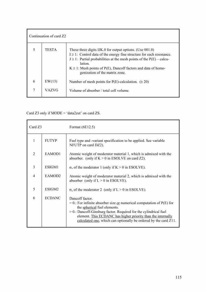
115
Continuation of card Z2 5 6 7
TESTA EW(13) VAZVG
These three digits IJK.0 for output options. (Use 001.0) I ≥ 1: Control data of the energy fine structure for each resonance. J ≥ 1: Partial probabilities at the mesh points of the P(E) – calcu- lation. K ≥ 1: Mesh points of P(E), Dancoff factors and data of homo- genization of the matrix zone. Number of mesh points for P(E)-calculation. (≅ 20) Volume of absorber / total cell volume.
Card Z3 only if MODE = ‘data2zut’ on card ZS.
Card Z3 Format (6E12.5) 1 2 3 4 5 6
FUTYP EAMOD1 ESIGM1 EAMOD2 ESIGM2 ECDANC
Fuel type and -variant specification to be applied. See variable NFUTP on card DZ2). Atomic weight of moderator material 1, which is admixed with the absorber. (only if K > 0 in ESOLVE on card Z2). σs of the moderator 1 (only if K > 0 in ESOLVE). Atomic weight of moderator material 2, which is admixed with the absorber (only if L > 0 in ESOLVE). σs of the moderator 2 (only if L > 0 in ESOLVE). Dancoff factor. = 0.: For infinite absorber size or numerical computation of P(E) for the spherical fuel elements. > 0.: Dancoff-Ginsburg factor. Required for the cylindrical fuel element. This ECDANC has higher priority than the internally calculated one, which can optionally be ordered by the card Z11.
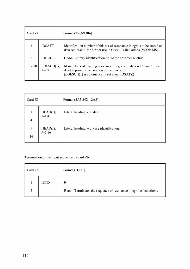
116
Card Z4 Format (2I6,6X,8I6) 1 2 3 - 10
IDSATZ IDNUCL LOESCH(J), J=2,9
Identification number of this set of resonance integrals to be stored on data set ‘resint’ for further use in GAM-I-calculations (VSOP-MS). GAM-I-library identification no. of the absorber nuclide. Id.-numbers of existing resonance integrals on data set ‘resint’ to be deleted prior to the creation of the new set. (LOESCH(1) is automatically set equal IDSATZ)
Card Z5 Format (4A3,24X,12A3) 1 . 4 5 . 16
HEAD(J), J=1,4 HEAD(J), J=5,16
Literal heading, e.g. date. Literal heading, e.g. case identification.
Termination of the input sequence by card Z6.
Card Z6 Format (I1,I71) 1 2
IEND
9 Blank: Terminates the sequence of resonance integral calculations.
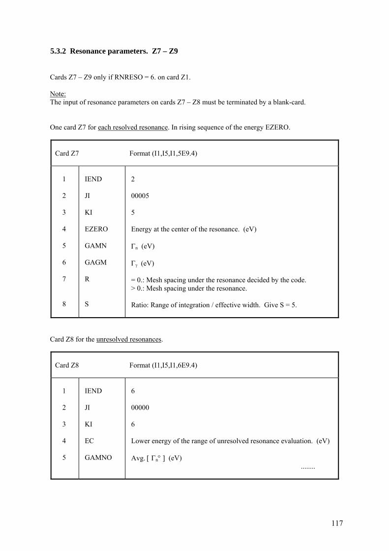
117
5.3.2 Resonance parameters. Z7 – Z9 Cards Z7 – Z9 only if RNRESO = 6. on card Z1. Note: The input of resonance parameters on cards Z7 – Z8 must be terminated by a blank-card. One card Z7 for each resolved resonance. In rising sequence of the energy EZERO.
Card Z7 Format (I1,I5,I1,5E9.4) 1 2 3 4 5 6 7 8
IEND JI KI EZERO GAMN GAGM R S
2 00005 5 Energy at the center of the resonance. (eV) Γn (eV) Γγ (eV) = 0.: Mesh spacing under the resonance decided by the code. > 0.: Mesh spacing under the resonance. Ratio: Range of integration / effective width. Give S = 5.
Card Z8 for the unresolved resonances.
Card Z8 Format (I1,I5,I1,6E9.4) 1 2 3 4 5
IEND JI KI EC GAMNO
6 00000 6 Lower energy of the range of unresolved resonance evaluation. (eV) Avg. [ Γn° ] (eV) ........
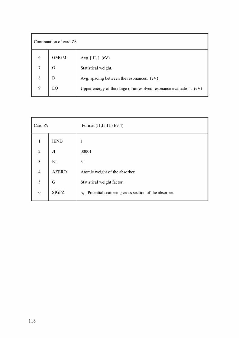
118
Continuation of card Z8 6 7 8 9
GMGM G D EO
Avg. [ Γγ ] (eV) Statistical weight. Avg. spacing between the resonances. (eV) Upper energy of the range of unresolved resonance evaluation. (eV)
Card Z9 Format (I1,I5,I1,3E9.4) 1 2 3 4 5 6
IEND JI KI AZERO G SIGPZ
1 00001 3 Atomic weight of the absorber. Statistical weight factor. σs . Potential scattering cross section of the absorber.
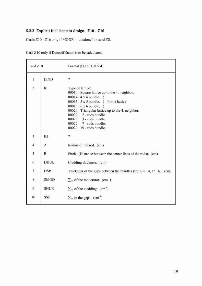
119
5.3.3 Explicit fuel element design. Z10 - Z16 Cards Z10 - Z16 only if MODE = ‘zutalone’ on card ZS. Card Z10 only if Dancoff factor is to be calculated.
Card Z10 Format (I1,I5,I1,7E9.4) 1 2 3 4 5 6 7 8 9 10
IEND K KI A B DHUE DSP SMOD SHUE SSP
7 Type of lattice: 00010: Square lattice up to the 4. neighbor. 00014: 4 x 4 bundle. } 00015: 5 x 5 bundle. } Finite lattice 00016: 6 x 6 bundle. } 00020: Triangular lattice up to the 4. neighbor. 00022: 2 - rods bundle. 00023: 3 - rods bundle. 00027: 7 - rods bundle. 00029: 19 - rods bundle. 7 Radius of the rod. (cm) Pitch. (Distance between the center lines of the rods). (cm) Cladding thickness. (cm) Thickness of the gaps between the bundles (for K = 14, 15, 16) (cm) ∑tot of the moderator. (cm-1) ∑tot of the cladding. (cm-1) ∑tot in the gaps. (cm-1)
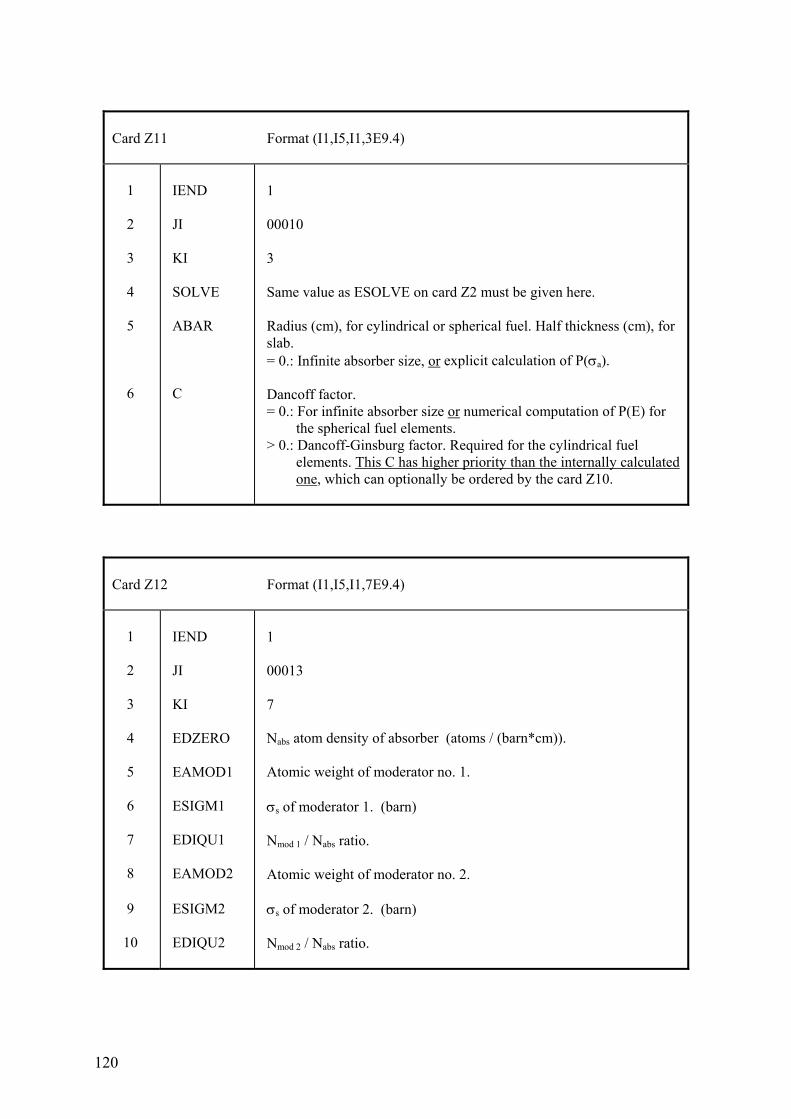
120
Card Z11 Format (I1,I5,I1,3E9.4) 1 2 3 4 5 6
IEND JI KI SOLVE ABAR C
1 00010 3 Same value as ESOLVE on card Z2 must be given here. Radius (cm), for cylindrical or spherical fuel. Half thickness (cm), for slab. = 0.: Infinite absorber size, or explicit calculation of P(σa). Dancoff factor. = 0.: For infinite absorber size or numerical computation of P(E) for the spherical fuel elements. > 0.: Dancoff-Ginsburg factor. Required for the cylindrical fuel elements. This C has higher priority than the internally calculated one, which can optionally be ordered by the card Z10.
Card Z12 Format (I1,I5,I1,7E9.4) 1 2 3 4 5 6 7 8 9 10
IEND JI KI EDZERO EAMOD1 ESIGM1 EDIQU1 EAMOD2 ESIGM2 EDIQU2
1 00013 7 Nabs atom density of absorber (atoms / (barn*cm)). Atomic weight of moderator no. 1. σs of moderator 1. (barn) Nmod 1 / Nabs ratio. Atomic weight of moderator no. 2. σs of moderator 2. (barn) Nmod 2 / Nabs ratio.
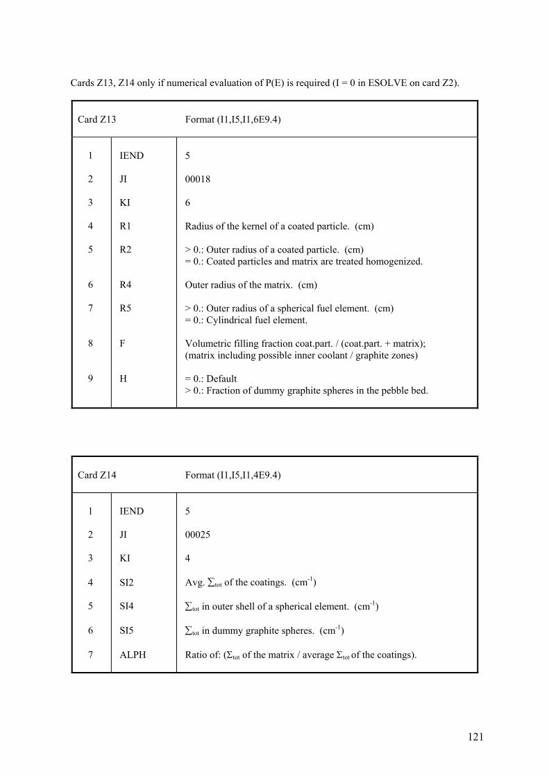
121
Cards Z13, Z14 only if numerical evaluation of P(E) is required (I = 0 in ESOLVE on card Z2).
Card Z13 Format (I1,I5,I1,6E9.4) 1 2 3 4 5 6 7 8 9
IEND JI KI R1 R2 R4 R5 F H
5 00018 6 Radius of the kernel of a coated particle. (cm) > 0.: Outer radius of a coated particle. (cm) = 0.: Coated particles and matrix are treated homogenized. Outer radius of the matrix. (cm) > 0.: Outer radius of a spherical fuel element. (cm) = 0.: Cylindrical fuel element. Volumetric filling fraction coat.part. / (coat.part. + matrix); (matrix including possible inner coolant / graphite zones) = 0.: Default > 0.: Fraction of dummy graphite spheres in the pebble bed.
Card Z14 Format (I1,I5,I1,4E9.4) 1 2 3 4 5 6 7
IEND JI KI SI2 SI4 SI5 ALPH
5 00025 4 Avg. ∑tot of the coatings. (cm-1) ∑tot in outer shell of a spherical element. (cm-1) ∑tot in dummy graphite spheres. (cm-1) Ratio of: (Σtot of the matrix / average Σtot of the coatings).
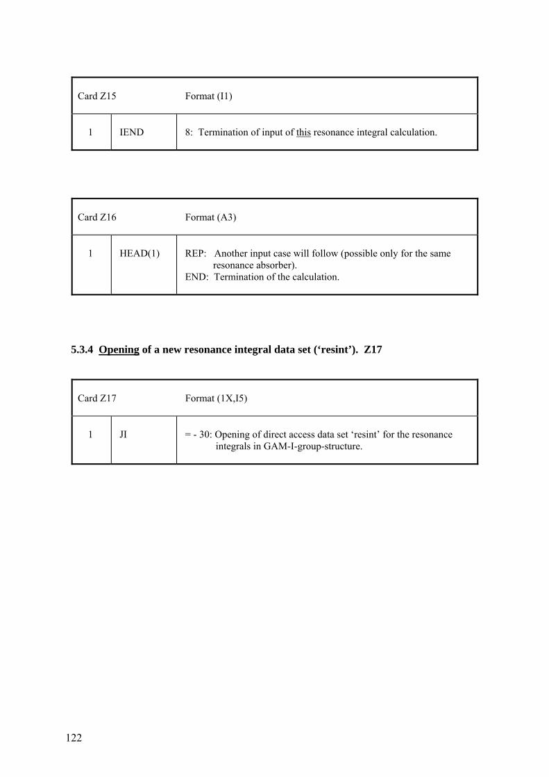
122
Card Z15 Format (I1) 1
IEND
8: Termination of input of this resonance integral calculation.
Card Z16 Format (A3) 1
HEAD(1)
REP: Another input case will follow (possible only for the same resonance absorber). END: Termination of the calculation.
5.3.4 Opening of a new resonance integral data set (‘resint’). Z17
Card Z17 Format (1X,I5) 1
JI
= - 30: Opening of direct access data set ‘resint’ for the resonance integrals in GAM-I-group-structure.
123
Appendix: Structure of the code and program tasks
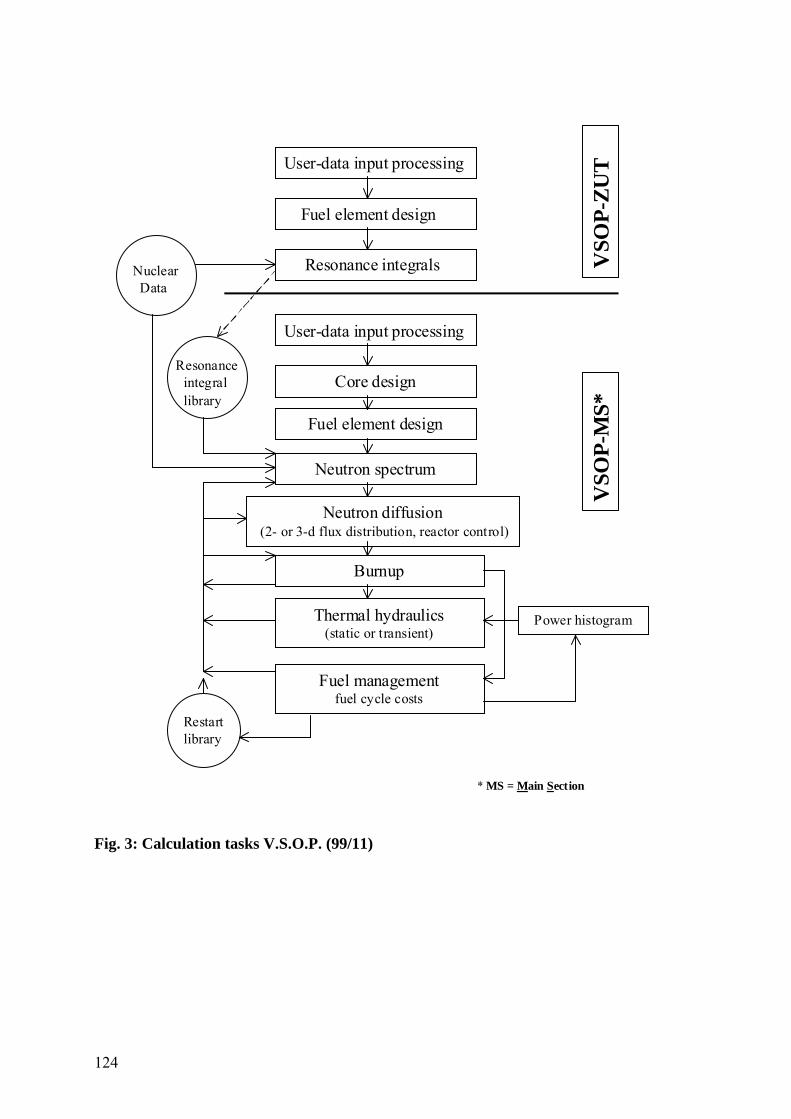
124
User-data input processing
Nuclear Data
Fuel element design
Resonance integrals
Neutron spectrum
Neutron diffusion (2- or 3-d flux distribution, reactor control)
Burnup
Thermal hydraulics(static or transient)
Power histogram
Fuel managementfuel cycle costs
Core design
Fuel element design
User-data input processing
Restartlibrary
VSO
P-ZU
T
Resonance integral library
VSO
P-M
S*
* MS = Main Section
Fig. 3: Calculation tasks V.S.O.P. (99/11)
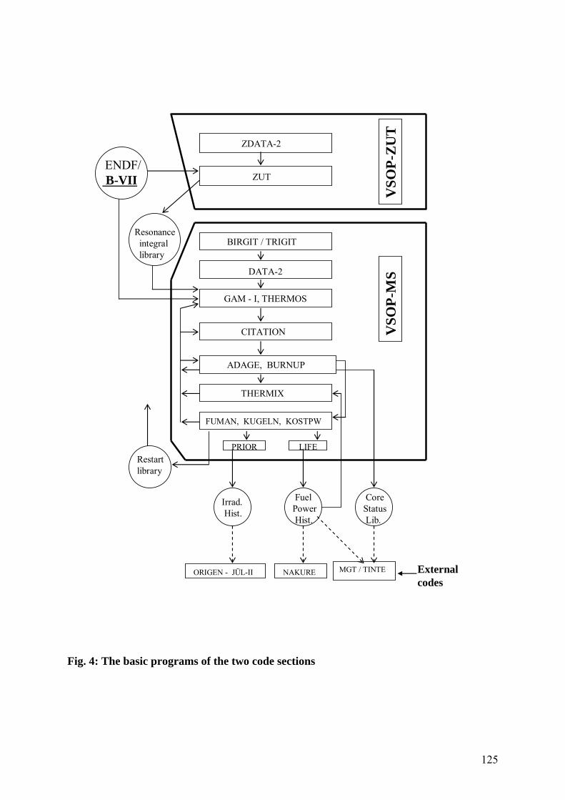
125
ENDF/B-VII
ZDATA-2
ZUT
GAM - I, THERMOS
DATA-2
Restartlibrary
VSO
P-ZU
T
Resonanceintegrallibrary
BIRGIT / TRIGIT
CITATION
ADAGE, BURNUP
THERMIX
FUMAN, KUGELN, KOSTPW
Irrad.Hist.
FuelPowerHist.
CoreStatusLib.
PRIOR LIFE
ORIGEN - JÜL-II NAKURE MGT / TINTE
VSO
P-M
S
Externalcodes
Fig. 4: The basic programs of the two code sections
126
References
/1/ H. J. Rütten, K. A. Haas, H. Brockmann, U. Ohlig, C. Pohl, W. Scherer: „V.S.O.P. (99/09) Computer Code System for Reactor Physics and Fuel Cycle Simulation; Version 2009 Jül-4326, June 2010 /2/ S. Rezgui: “Erweiterung der Resonanzdatenbasis für stationäre und transiente Neutronentransportprogramme“ Diplomarbeit Institut für Kernphysik, Universität Köln und Institut für Energie- und Klimaforschung (IEK-6), Forschungszentrum Jülich October 2011


Jül-4348Januar 2012ISSN 0944-2952