Embed Size (px)
Citation preview

Technical Practiceand
Installation Manual
Copyright GE Power Management 2001©
342342--8640086400--447PS447PSIssue 1Issue 1March 1994March 1994
86447 LS DATA UNIT
JungleMUXJungleMUXSONETSONET MultiplexerMultiplexer
GE PowerManagement
Technical Practiceand
Installation Manual
Copyright GE Power Management 2001©
342342--8640086400--447PS447PSIssue 1Issue 1March 1994March 1994
86447 LS DATA UNIT
JungleMUXJungleMUXSONETSONET MultiplexerMultiplexer
GE PowerManagementGE PowerManagement

342-86400-447PS Issue 1 March 1994 Page 2
Copyright GE Power Management 2001
TABLE OF CONTENTS SECTION PAGE
1. INTRODUCTION ............................................... 5
Related Publication and Documentation Support ............................ 5 Handling and packing ......................................................................... 6
2. UNIT OVERVIEW ............................................... 7 3. FRONT PANEL FEATURES .............................. 8 LED Indications......................................................................................... 8 Push-Button (ACK) ................................................................................... 8 Craft Interface Jack .................................................................................. 8 4. UNIT DESCRIPTION .......................................... 9 Transmit Signal Path ................................................................................ 9 Receive Signal Path................................................................................. 10 Control Signals ........................................................................................ 10 Micro-Processor Operation..................................................................... 11 5. INSTALLATION................................................. 13 Preinstallation .......................................................................................... 13 Shelf Position........................................................................................... 13 Power Requirements ............................................................................... 13 Paddle Board Connections..................................................................... 14

342-86400-447PS Issue 1 March 1994 Page 3
Copyright GE Power Management 2001
SECTION PAGE 6. CONFIGURATION............................................. 16 Unit Setup................................................................................................. 16 Monitors.................................................................................................... 17 Unit Monitoring ........................................................................................ 18 7. MAINTENANCE and TROUBLESHOOTING .... 20 F1 Help...................................................................................................... 20 Alignment ................................................................................................. 20 Troubleshooting ...................................................................................... 20 8. UNIT PARAMETERS......................................... 21 RS-232 Signal Conversion ...................................................................... 21 RS-232 Signal Support ............................................................................ 21 Data Transitions....................................................................................... 22 End-to-End Delay..................................................................................... 22 9. SPECIFICATIONS............................................. 23 Physical. ................................................................................................... 23 Electrical................................................................................................... 23 Environmental.......................................................................................... 23 Mechanical ............................................................................................... 24 EMI/RFI...................................................................................................... 24 Isolation.................................................................................................... 24 Reliability.................................................................................................. 24 10.ORDERING INFORMATION............................. 25 Equipment and Option Code List ........................................................... 25
342-86400-447PS Issue 1 March 1994 Page 4
Copyright GE Power Management 2001
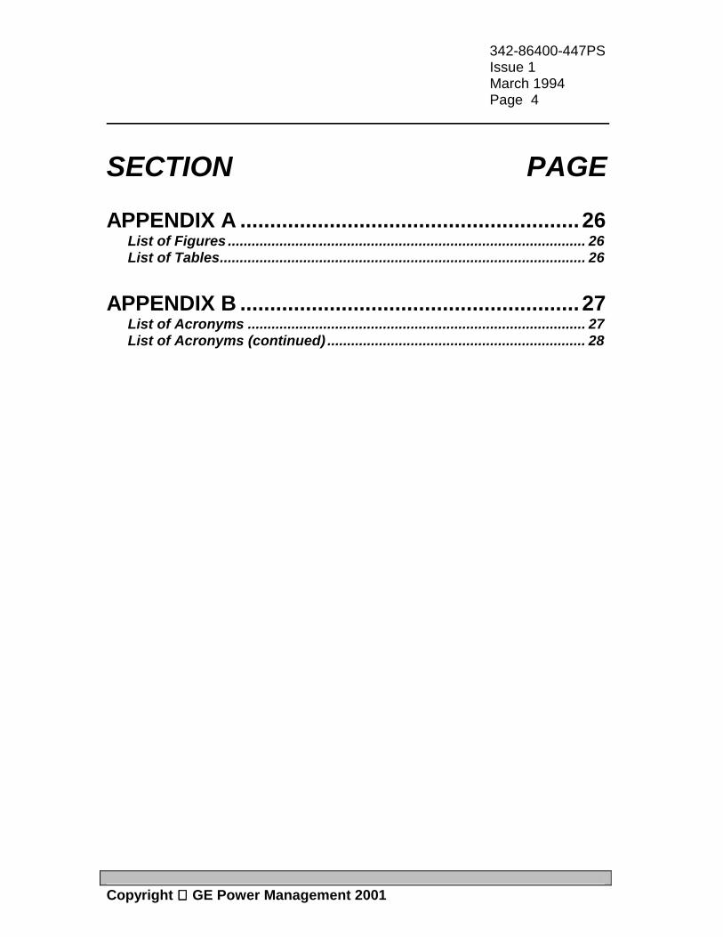
SECTION PAGE APPENDIX A ......................................................... 26 List of Figures .......................................................................................... 26 List of Tables............................................................................................ 26 APPENDIX B ......................................................... 27 List of Acronyms ..................................................................................... 27 List of Acronyms (continued) ................................................................. 28
342-86400-447PS Issue 1 March 1994 Page 5
Copyright GE Power Management 2001
1. INTRODUCTION
The 86447 LS DATA unit is one of the family of channel units in the Lentronics JungleMUX digital transport/access system designed specifically for the requirements of the utility industry using optical fiber transmission. This manual explains how to operate, install and maintain the LS DATA unit. A unit description and block diagram is included which details the operation of the unit. Engineering documentation includes EAS schematics for all unit circuitry. Related Publication and Documentation Support Additional information is provided in the 86400 Technical Overview and Reference Manual for system planning and engineering. The user may also find useful information contained in other 86400 Technical Practice and Installation Manuals. Customer inquires for information contained in this manual should be directed to JungleMUX Product Line Management. GE Power Mangement appreciates notification of any possible errors or omissions contained herein. Shipped with all purchased systems is a Node Assignment Drawing which provides necessary configuration details for the units. Channel, VT, JIF and JMUX, are some of the assignments that are shown on the Node Assignment Drawing.

342-86400-447PS Issue 1 March 1994 Page 6
Copyright GE Power Management 2001
Handling and Packing Equipment with Electrostatic Discharge Sensitive (ESDS) devices or components must be shipped in protective containers and necessary handling precautions observed otherwise all warranties, expressed or implied, will be considered null and void. The following Electronic Industries Association (EIA) attention label appears on all GE Power Mangement EAS schematics and should be attached on all containers used for ESDS items to alert personnel that the contents requires special handling.
HANDLE & ASSEMBLE
THIS UNIT CONTAINS STATIC SENSITIVE DEVICES
PER 562-48043-01SENSITIVE
ELECTROSTATIC
OBSERVE PRECAUTIONSFOR HANDLING
ATTENTION
DEVICES

342-86400-447PS Issue 1 March 1994 Page 7
Copyright GE Power Management 2001
2. UNIT OVERVIEW The 86447 LS DATA unit provides up to four 9.6 kb/s full-duplex asynchronous data ports along with four end-to-end RS232 control signals over a single 64 kb channel. Data transmission is transparent, irregardless of baud rate, start, stop, or data bits. The 86447 LS DATA unit can be configured with one, two or four active data ports with maximum baud rates of 38.4 kb/s, 19.2 kb/s and 9.6 kb/s respectively. All ports will accept sub-multiple rates of the programmed maximum baud rate. Front panel LEDs provide monitoring of transmit and receive data activity for all four available ports. The unit occupies one shelf slot in an 86430 shelf and requires one channel assignment of the 24 available channels in a JMUX VT.

342-86400-447PS Issue 1 March 1994 Page 8
Copyright GE Power Management 2001
3. FRONT PANEL FEATURES
Led Indications Alarm (red) Denotes when the unit has lost either Shelf Framing, Data Framing or operates at an out of temperature range. Shelf Framing refers to the 2 kHz shelf SYNC clock and must first be established before a Data Framing alarm can occur. After shelf SYNC has been detected, the local and remote units exchange messages to establish Data Framing. Shelf Framing alarms usually occur if there are no JIF or JMUX units present. Xmt and Rcv (green) These leds are green (steady) if the ports have been configured but no data activity is present on the transmit or receive terminals. These leds are green (blinking) if data transitions are occurring on the transmit and receive terminals. Note: All led indications are controlled by the micro-processor.
Push-button (ACK) The main use is a led and micro-processor test; pressing the button causes all the leds to light. The second use is to put the micro-processor into a "Forth Loop" state. In this condition, the micro ignores all settings until the JCI software is run. The JCI will automatically clear the Channel Assignment setting (--) at which point the user can configure the unit to the desired settings. If the unit is inserted with the ACK button pressed and then removed and inserted normally (no JCI), all previous settings will return. Craft Interface (C.I.) Jack This is a serial RS232 9600 b/s port for connection to a 386 or better PC. The supplied JCI software enables the user to configure the unit and monitor the units status.
LS-DATA UNIT
C.I.
86447-01
ACK
RCVALARM
XMT4
3
1
2
Figure 1Front Panel Layout

342-86400-447PS Issue 1 March 1994 Page 9
Copyright GE Power Management 2001
4. UNIT DESCRIPTION The 86447 LS DATA unit can be configured with up to four data ports however, the following description is for circuit one only. Signal paths for circuits two, three, and four will be identical as circuit one except for designations, locations, etc. All user connections are made to the 86447-90 Interconnect Paddle Board. Four terminal blocks provide transmit data, receive data, signal ground, transmit control and receive control interfaces for all four circuits. All pinout arrangements are provided in the Installation Section of the manual. A simplified Block Diagram has been included at the end of this section and can be used for reference for the following signal paths analysis, however the user should refer to schematics EAS-86447-M1 for complete circuit descriptions. Transmit Signal Path The XMT DATA IN bits are received on Paddle Board TB1(1) and sent to the back connector J1(C1) of the main assembly board 087-86447-01. Plug P4(1) routes the signal to the RS-232 Interface Assembly Board 087-86447-02 via J4(1). U4 on the Interface Assembly Board provides the electrical interface to the Paddle Board and the necessary level translation and protection from the various interfaces for the Programmable Logic Gate Array (U2). J2(15) passes the signal back to the main assembly board on P2(15) to the capacitor chip array CN3(12) which provides EMI filtering and suppression for U2. U2(5) accepts the signal where it is processed and routed through various gate arrays in the chip. The signal is outputted on U2(78) to the output driver U8. The JVT Interface J1(C14, A14) consists of a balanced 50 ohm RS-422 signal pair designed for multi-point transmission. The unit receives its clock source from the JVT Bus J1(C15, A15) through the input driver U6. The JVT serial bus operates at 2.592 MHz.

342-86400-447PS Issue 1 March 1994 Page 10
Copyright GE Power Management 2001
Receive Signal Path The receive data bits are received by the input driver U7 from the JVT Bus J1(C16, A16) and sent to U2(77). U2 processes the signal and routes it through various gate arrays on the chip. U2(4) outputs the signal to the capacitor chip array CN3(7), and passes the signal from (11) to Plug P2(16). The signal is then sent to the Interface Assembly Board on J2(16) to U4(11). U4 provides the electrical interface for the Paddle Board. The signal is sent back to the main assembly board via J4(4); P4(4); and terminated on the Paddle Board TB1(2) as RCV DATA OUT. Control Signals Each port is accompanied by RS-232 transmit and receive control signals with a maximum bandwidth of 300 bits/s. The primary function of the control signals are to provide an uncommitted virtual wire between two LS DATA units. The state of the receive control signal is determined by the following configuration options: 1) End - To - End: The state asserted on the transmit signal is reflected at the receive end of the corresponding control signal. 2) Loop back: The receive control signal reflects the state of the local transmit control signal. 3) Set High: The receive control signal is set to a logic '1'; MARK condition. 4) Set Low: The receive control signal is set to a logic '0'; SPACE condition. XMT and RCV CONTROL signals are terminated on the Paddle Board TB1(4,5) where they are sent to U2 in exactly the same manner as the data information.

342-86400-447PS Issue 1 March 1994 Page 11
Copyright GE Power Management 2001
Micro-Processor Operation U1, the 68HC11 micro-processor, is the CPU for the LOW SPEED DATA unit and is configured for single chip operating mode. The CPU provides the following: • Communication with the user through the Craft Interface port. • Controls all front panel leds and processes the activation of the ACK push
button switch. • Monitors the precision temperature sensor LM34(U9) for local unit
temperatures and alarms accordingly. • Controls configuration of PLGA U2 Crystal Y1 provides the 8.0 MHz clock to the micro-processor. On chip memory includes 8 kBytes of ROM, 512 bytes of EEPROM, and 256 bytes of RAM.

342-86400-447PS Issue 1 March 1994 Page 12
Copyright GE Power Management 2001
Figure 2: Block Diagram LS DATA Unit

342-86400-447PS Issue 1 March 1994 Page 13
Copyright GE Power Management 2001
5. INSTALLATION The following section provides a step-by-step procedure for installing a 86447 LS DATA unit. The LS DATA unit's nonvolatile memory is shipped from the factory as per the node assignment drawing for the purchased system. All spare units or loose units are shipped with factory default settings in memory.
CAUTION The 86447 LS DATA unit has ESDS components and therefore standard
static protection precautions should be observed when handling, packing or shipping the unit.
Preinstallation Visually check the unit for damage. Ensure that all jumpers, if applicable, and screws are firmly tightened or in place. Keep the shipping containers and packing materials for future use. If a unit is damaged, file a claim with the shipping agent or representative and call the Product Support Center referred to at the start of the manual. Shelf Position The LS DATA unit and associated Paddle Board can be inserted in channel slots 2 to 14 of a 86430-02 shelf or in slots 2 to 9 of a 86430-01 common equipment shelf. The remaining slots are reserved for common equipment units. Figure 3 shows a typical rack layout for a ring configured system dropping a maximum of seven VTs. The LS DATA unit can be inserted and removed from the shelf with shelf power applied. Power Requirements Power for the 86447 LS DATA unit is supplied from the shelf, therefore no external power supply is required.

342-86400-447PS Issue 1 March 1994 Page 14
Copyright GE Power Management 2001
CHAN3
4W E&M 2W FXO
RIGHT
PWRJMUXSERVICE
RACK MOUNT POSN_1_
1 152 3 4 5 6 7 8 9 10 11 12 13 14UNIT SH
SLOT
RACK MOUNT POSN_2_
RACK MOUNT POSN_3_
FIBRES TO:
SYNC MODE
LEFT
JMUX
FIBRES TO:
RING HEADEND
CHAN2
CHAN1
HS DATA HS DATAPWR 2W FXO 2W FXO JPOS 1
JIF L JIF R
CHAN4
4W E&M LS DATA
JVT-S (JPOS1) VT 1
PWRPWR
21 3CHAN CHAN CHAN CHANCHAN CHAN
54 6
2W FXO 2W FXO
7
2W FXO
CHAN CHAN1 1
DTT XMT DTT RCV
JVT-S (JPOS2) VT 3
CHAN
JPOS 2
JIF L JIF R
LS DATA
CHAN7
HS DATA
CHAN8
PWRPWR
21 3CHAN CHAN CHAN
TELE 2W FXS
CHAN4
2W FXS
CHAN5
JIF DS1
CHAN
6
2W FXS
JVT-R (JPOS2) VT 5
BLANK BLANK BLANK JIF DS1
JVT-R (JPOS1) VT 2CHAN
3CHAN
2CHAN
1CHAN
4
BLANKBLANKBLANK 2W FXO
TELE4W VF
JVT-Q (JPOS2) VT 4
86429-M1 DTT TEST PANEL
CCT 1 CCT 2 CCT 3 CCT 4 CCT 1 CCT 2 CCT 3 CCT 4
TRANSMIT RECEIVE
DS1-S, VT6
Figure 3: Typical Rack Layout Paddle Board Connections Each LS DATA unit requires one 86447-90 Paddle board. The Paddle board allows termination of the RS-232 signals. Figure 4 details the Paddle board connections. Although the Paddle Board has screw-type connectors, the unit can be ordered with patch cords to interface the desired connector of the customer equipment (DB9 or DB25). Cable lengths and connector type would have to be specified. Cables designed for EIA RS-232 applications are recommended with allowable line lengths ≤100 feet (30 meters).

342-86400-447PS Issue 1 March 1994 Page 15
Copyright GE Power Management 2001
Figure 4: LS DATA Unit Paddle Board Description
LS DATA PADDLE BOARD
86447-90
1 2 3 4 5
1 2 3 4 5
1 2 3 4 5
1 2 3 4 5
TB1 TB3
TB2 TB4
C B A
C1 A1
86447-90 PADDLEBOARD
TD 1 RD 1
CONTROL IN 1 CONTROL OUT 1
TD 2 RD 2
CONTROL IN 2 CONTROL OUT 2
TD 3 RD 3
CONTROL IN 3 CONTROL OUT 3
TD 4 RD 4
CONTROL IN 4 CONTROL OUT 4
PIN
1 2 3 4 5 6 7 8
15 17 20 21 22 23
INTERCONNECT
Shield Transmit Data Receive Data Request To Send Clear To Send Data Set Ready Signal Ground Received Line Signal Detector Transmitter Signal Element Detector Receiver Signal Element Detector Data Terminal Ready Signal Quality Detector Ring Indicator Data Signal Rate Selector
ABRV.
-- TD RD
RTS CTS DSR SG CD -- --
DTR -- RI --
C. IN C. OUT
X X X X
X X X X X X
RS - 232 INTERFACE
Kb/s
9.6
19.2
38.4
CHANNELS TERMINAL NOTES
max. 4
max. 2
max. 1
TB1 thru TB4
TB1 and TB2 only
TB1 only
Where less than 4 channels are equipped it is possible to utilize the control lines on the unused TB's if required. Where only 1 channel is equipped the control lines on TB2 are available if required.TB1 control lines only.
NOTES:
The 86447-90 paddle board services both high and low speed data units.

342-86400-447PS Issue 1 March 1994 Page 16
Copyright GE Power Management 2001
6. CONFIGURATION To configure the 86447 LS DATA unit , connect a PC running the supplied Junglemux Craft Interface (JCI) software to the CI jack on the front of the unit. A 84910-05 RJ-45 cable and an 84910-06 (9 pin adapter) or 84910-07 (25 pin adapter) or equivalent are required. The software will display necessary programmable fields and also information about the unit and the status of the unit. The unit will be shipped with the programmable fields set as per the Node Assignment Drawing for the purchased system. The LS DATA unit does not have any hardware adjustable options. All options for the JVT portion of the unit is shown in JCI screen Figure 5. JCI SCREEN INFORMATION
Unit Setup JMUX CHANNEL
Channel numbers are selectable from 1 thru 24. Each JMUX channel occupies it's own time slot within a VT thereby making it mandatory that no two channels be allocated the same number on the same VT. The corresponding LS DATA unit ( at the far end node ) must be given the same channel number.
RACK NUMBER
Identifies rack or cabinet in which the unit is located. This information will be utilized on the NMS (Network Management System).
RACK MOUNT POSITION
Identifies location of shelf in which the unit is located for NMS. UNIT'S SHELF SLOT
Identifies which slot position within the shelf ( 1 thru 15 ) that the unit is located in for NMS.

342-86400-447PS Issue 1 March 1994 Page 17
Copyright GE Power Management 2001
NUMBER OF PORTS
User selectable from 1 to 4. Maximum baud rate is automatically programmed by the number of ports chosen. All ports will accept sub-multiple rates of the programmed maximum baud rate. NOTE: This unit is asynchronous only.
Monitors DATA - SEND/RECEIVE
Shows current status of all four ports. May be IDLE or ACTIVE. IDLE status is displayed on the unit's face plate by a steady green LED while ACTIVE status is denoted by a flashing green LED. Each port is indicated on the unit by two LEDs. Left side is transmit, right side is receive and ports count from top to bottom. The unit's LEDs will illuminate for the number of ports that are currently configured.
CONTROL - SEND/RECEIVE
May be either HIGH (mark) or LOW (space). The status of the control lines is determined by the user's drop equipment, however, the receive control lines may be forced HIGH or LOW by editing the RECEIVE CONTROL MODE on the JCI screen. NOTE: The control lines act as one way (simplex)virtual wires and may be used for any of the control functions typically supported by RS-232. See LS DATA Paddle Board diagram for interface information.

342-86400-447PS Issue 1 March 1994 Page 18
Copyright GE Power Management 2001
RECEIVE CTRL MODE
May be one of four options:
1) END - TO - END In this configuration the condition asserted locally on the control-in line (transmit) will be reflected at the control-out line (receive) of the corresponding (far end) port.
2) LOOP BACK This loops the control lines locally within the unit.
The status of the control-in line will be reflected on the control-out line.
NOTE: This does not loop back the DATA in/out lines. 3) SET HIGH This forces the local control-out line (receive) HIGH
(mark) regardless of any incoming line status. Allows the user to simulate a 'break-out box' for test purposes.
4) SET LOW Same as above only with LOW (space) condition on
receive control-out line. Unit Monitoring DATA FRAMING (Not Adjustable)
'OK' indicates normal operation. SHELF CLOCK (Not Adjustable)
'OK' indicates normal operation.
TEMPERATURE (Not Adjustable) Indicates current LS DATA operating temperature.

342-86400-447PS Issue 1 March 1994 Page 19
Copyright GE Power Management 2001
Figure 5: LS DATA Unit JVT Screen Display
LENTRONICS JUNGLEMUX CRAFT INTERFACE PROGRAM VER. 1.XX
86447 LOW SPEED DATA UNIT S/N 01-01- XXXX
86447 LS DATA UNIT SCREEN DATA
UNIT SETUPJMUX CHANNEL : 1 RACK NUMBER : 1 RACK MOUNT POSITION : 1 UNIT'S SHELF SLOT : 1 NUMBER OF PORTS : 4 MAX. BAUD RATE 9.6 Kb/s
F1: HELP F3: Configure F7: About Unit ESC: EXIT TO DOS
PRESS "F3" SELECT PARAMETER TO BE EDITED BY TOGGLING UP AND DOWN ARROWS ON KEYBOARD. PRESS "F5" EDIT PARAMETER BY TOGGLING LEFT AND RIGHT ARROWS ON KEYBOARD THEN PRESS "ENTER".
UNIT MONITORINGDATA FRAMING : OK SHELF CLOCK : OK TEMPERATURE : 23 C
DATA SEND ACTIVE IDLE IDLE IDLE RECEIVE ACTIVE IDLE IDLE IDLE CONTROL SEND LOW HIGH HIGH HIGH RECEIVE LOW HIGH HIGH HIGH RECEIVE CTRL MODE END-TO-END END-TO-END END-TO-END END-TO-END
PORT 1 PORT 2 PORT 3 PORT 4
DISPLAYS UNIT SERIAL # AND FIRMWARE VERSIONS
PRESS TO HIGHLIGHT ADJUSTABLE PARAMETERS

342-86400-447PS Issue 1 March 1994 Page 20
Copyright GE Power Management 2001
7. MAINTENANCE and TROUBLESHOOTING F1 Help The "F1" key can be a useful tool for explaining the capabilities and options of both programmable fields and display fields of the unit. The user selects "F1" from the JCI screen and then chooses the topic he/she wishes information on. Alignment The 86447 LS DATA unit must be correctly configured as per the Node Assignment Drawing. All software adjustable fields are detailed in the Configuration Section of this manual. The user must ensure that all external connections to the Interconnect Paddle Board are correct. Troubleshooting If a 86447 LS DATA unit is suspected of being defective, substitute it for a known-good 86447 unit and if the unit functions properly return the original to GE Power Mangement for repair or replacement. Ensure that the substitute unit is configured correctly. The follow table is intended to provide the user with possible solutions to problems that may be encountered during normal unit operation. Service affecting problems can be directed to GE Power Mangement ETAC service which is outlined at the beginning of this manual.
Symptom Probable Cause / Solution No transmission in either transmit or receive direction.
- Ensure that JIF or JMUX units are not in alarm and that VT path is correct. - Ensure that local and remote unit configuration is correct. - Receive Control Mode commands are "End-to-End".
Table 1: Troubleshooting Table

342-86400-447PS Issue 1 March 1994 Page 21
Copyright GE Power Management 2001
8. UNIT PARAMETERS
RS-232 Signal Conversion The LOW SPEED DATA unit is equipped with an Interface Assembly Board that provides the necessary conversion for standard EIA RS-232/CCITT V.24 Transmit and Receive Data levels. The daughter board contains sixteen RS-232 drivers and receivers to provide the level conversion. The parameters for these devices is shown in the following table:
PARAMETER Min Typ Max Unit RS-232 Transmitter Output Voltage Swing ±5.0 ±8.0 Volts
Input Logic Threshold Low 1.4 0.8 Volts Input Logic Threshold High 2.0 1.4 Volts
RS-232 Receiver Input Voltage Swing ±30 Volts Input Threshold Low 1.3 2.4 Volts Input Threshold High 2.0 1.8 Volts
Table 2: RS-232 Conversion Parameters
RS-232 Signal Support The LOW SPEED DATA unit supports the following EIA RS-232 signals for all ports: • Transmit Data (TD) • Receive Data (RD) • Signal Ground (SG) Each port is also equipped with a Control Lead labeled as Control In and Control Out. These user defined signals can be configured for various applications as outlined in the Unit Description section of the manual.

342-86400-447PS Issue 1 March 1994 Page 22
Copyright GE Power Management 2001
Data Transitions Port and Data Rates are as follows: • One Port maximum baud rate 38.4 kb/s • Two Ports maximum baud rate 19.2 kb/s • Four Ports maximum baud rate 9.6 kb/s • Data Bits, Parity, Stop Bits Transparent End-to-End Delay Total End-to-End Delay for the 86447 LOW SPEED DATA unit is: • ≈ 1.0 ms @ 38.4 kb/s • ≈ 2.0 ms @ 19.2 kb/s • ≈ 4.0 ms @ 9.6 kb/s

342-86400-447PS Issue 1 March 1994 Page 23
Copyright GE Power Management 2001
9. SPECIFICATIONS Physical: The LS DATA unit is housed in a standard JMUX channel mechanics and occupies a single shelf slot with the following dimensions: 1) Height: 89 mm (3.5 inches) 2) Width: 29 mm (1.135 inches) 3) Depth: 203 mm (8 inches) 4) Weight: 184 grams (6 oz) Connector Type: Paddle Board Screw Type Connecto Electrical: The input power requirements for the LS DATA unit are: 1) Voltage: 5.0 VDC ±5% 2) Current: 167 mA @ +5 VDC 3) Power Consumption: 0.8 W (Idle) This voltage is supplied from the 86430 Equipment Shelf. Environmental: 1) Temperature: Guaranteed Performance: -20 to +60 C (-5 to +150 F) Storage: -40 to +70 C (-40 to +158 F) 2) Relative Humidity: 5 to 95% @ 40 C, non-condensing, 10 days 3) Shipping Altitude: 15,000 meters (50,000 feet)
342-86400-447PS Issue 1 March 1994 Page 24
Copyright GE Power Management 2001
Mechanical: 1) Vibration: per MIL-STD 810E 2) Bench Handling: per TS 1-00446.06 EMI/RFI: Meets ANSI/IEEE C37.90.2 RFI specification Isolation: Meets ANSI/IEEE C37.90.1 for surge withstand and fast transients Reliability: The calculated Mean Time Between Failure (MTBF) as per Bell technical advisory TR-NWT-000332 for the LS DATA unit is: MTBF = 285,000 Hours (32 Years)

342-86400-447PS Issue 1 March 1994 Page 25
Copyright GE Power Management 2001
10. ORDERING INFORMATION This section covers the ordering information for a single 86447 LS DATA unit and is not intended to replace standard engineering documentation or drawings. Please contact your Account Manager for your area regarding ordering the 86447 LS DATA unit and it's options. Equipment and Option Code List
Equipment Option Code
Description
86447 -01 Provides the interface for up to 4 9.6 kbits/s asynchronous data ports/unit and a JMUX node.
86447 -90 Paddle Board Assembly; One required for every 86447-01 unit.
Table 3: Equipment and Option Code Table

342-86400-447PS Issue 1 March 1994 Page 26
Copyright GE Power Management 2001
APPENDIX A
LIST OF ILLUSTRATIONS
List of Figures
FIGURE # DESCRIPTION PAGE 1 Front Panel Layout 8 2 Block Diagram - LS DATA Unit 12 3 Typical Rack Layout 14 4 Paddle Board Connections 15 5 LS DATA Unit JVT Screen 19
List of Tables
TABLE # DESCRIPTION PAGE 1 Troubleshooting Table 20 2 RS-232 Conversion 21 3 Equipment & Option Table 25

342-86400-447PS Issue 1 March 1994 Page 27
Copyright GE Power Management 2001
APPENDIX B
LIST OF ACRONYMS
• AIS Alarm Indication Signal • AMI Alternate Mark Inversion • BER Bit Error Rate • BPV Bipolar Violation • B8ZS Bipolar with 8 Zero Substitution • CPU Central Processing Unit • CRC Cyclic Redundancy Check • DS1 Digital Signal 1 • EAS Equipment Assembly Schematic • EIA Electronic Industries Association • EMI Electro Magnetic Induction • ESDS Electrostatic Discharge Sensitive • ETAC Emergency Technical Assistance Center • JCI JUNGLEMUX Craft Interface • JIF JUNGLEMUX Intermediate Format • JMUX JUNGLEMUX • LBO Line Build Out

342-86400-447PS Issue 1 March 1994 Page 28
Copyright GE Power Management 2001
APPENDIX B
LIST OF ACRONYMS (continued)
• LED Light Emitting Diode • LOS Loss Of Signal • LRT Line Rate Tolerance • LTM Local Test Mode • LTR Local Trip Mode • MTBF Mean Time Between Failures • MTTR Mean Time To Repair • NMS Network Management System • PLGA Programmable Logic Gate Array • PSC Product Support Center • RAM Random Access Memory • RCV Receive • ROM Read Only Memory • RFI Radio Frequency Interference • SWC Surge Withstand Capability • UI Unit Interval • VT Virtual Tributary • XMT Transmit