Embed Size (px)
Citation preview
June 2020
Standard Metal Building Specifications
(These specifications are subject to change without notice.)
CONTENTS
Section 1: General
Section 2: Structural Steel Design
Section 3: Traditional Metal Building System Basic Material Specifications
Section 4: Roof and Wall Covering Material Specifications
Section 5: Miscellaneous Material Specifications
Section 6: Accessories
Section 7: Erection & Installation
Section 8: Building Anchorage and Foundations
Annex A: References
June 2020
SECTION 1. GENERAL
A. Scope
1. These specifications cover the materials and the fabrication of metal buildings designed, fabricated, and delivered to be readily erected to be weather-tight.
2. These specifications are an outline of performance to ensure that the architect, engineer, builder and/or owner understand the basis for design, manufacture, and application of the entire manufacturer’s metal building system.
3. Because of a continuing program of research and development, specifications in this manual are subject to change without notice.
B. Building Description
1. Gable Symmetrical is a continuous frame building with the ridge in the center of the building, consisting of tapered or straight columns and tapered or straight rafters. The sidewall girts may be continuous (by-passing the columns) or simple span (flush in the column line). The rafters may or may not have interior columns.
2. Gable Unsymmetrical is a continuous frame building with an off-center ridge, consisting of tapered or straight columns and tapered or straight rafters. The eave height and roof slope may differ on each side of the ridge. The sidewall girts may be continuous (by-passing the columns) or simple span (flush in the column line). The rafters may or may not have interior columns.
3. Single Slope is a continuous frame building, which does not contain a ridge, but consists of one continuous slope from side to side. The building consists of straight or tapered columns and tapered or straight rafters. The sidewall girts may be continuous (by-passing the columns) or simple span (flush in the column line). The rafters may or may not have interior columns.
4. Lean-to (LT) is a building extension, which does not contain a ridge, but consists of one continuous slope from side to side. These units usually have the same roof slope and girt design as the building to which they are attached.
5. All building types normally have simple span endwall girts flush in the column line.
C. Building Nomenclature
1. Building “Width” is measured from outside to outside of sidewall secondary structural member (girt).
2. Building “Eave Height” is a nominal dimension measured from the finished floor to the top flange of eave strut.
3. Building “Length” is measured from outside to outside of endwall secondary structural member.
4. Roof slope is expressed as inches of rise for each 12” of horizontal run.
June 2020
D. Drawings and Certifications
1. Drawings: Manufacturer shall furnish complete erection drawings for the proper identification and assembly of all building components. These drawings will show anchor bolt settings, transverse cross- sections, sidewall, endwall and roof framing, flashing and sheeting, and accessory installation details.
2. Certifications: Standard drawings and design analysis shall bear the seal of a registered professional engineer. Design analysis shall be on file and furnished by manufacturer upon request.
3. A letter of certification shall be provided containing all pertinent structural design information that is required to be indicated on the construction documents, as noted in Section 1603 of the applicable edition of the IBC. This letter shall be sealed in accordance with the engineering laws of the appropriate jurisdiction.
4. SBI is Accredited under IAS AC472 Metal Building Program. Certificate MB-153
5. Bills of material (Shipper) shall be furnished.
SECTION 2. STRUCTURAL STEEL DESIGN
A. General
1. The building manufacturer shall use standards, specifications, recommendations, findings and/or interpretations of professionally recognized groups such as IBC, AISC, AISI, AAMA, AWS, ASTM, MBMA, Federal Specifications, and unpublished research by MBMA as the basis for establishing design, drafting, fabrication, and quality criteria, practices, and tolerances. For convenience, one or more sources may be referenced in a particular portion of these specifications. In all instances, however, the manufacturer’s design, drafting, fabrication and quality criteria, practices and tolerances shall govern, unless specifically countermanded by the contract documents. Structural mill sections or welded up plate sections will generally be designed in accordance with the current edition of AISC’s “Specification for the Design, Fabrication and Erection of Structural Steel for Buildings”, ASD method.
2. Cold-Formed steel structural members will generally be designed in accordance with the current edition of AISC’s “Specifications for the Design of Cold-Formed Steel Structural Members”.
3. See Annex A for list of additional Specifications used in Design and Manufacturing)
B. Design Loads
1. Design loads shall be as specified and set forth in the contract and shall be in accordance with the manufacturer’s standard design practices. Design loads may include dead load, roof live loads, wind loads, seismic loads, collateral loads, auxiliary equipment loads, and/or other applied or specified loads.
2. Wind Loads – the loads on a structure induced by the forces of wind blowing from any horizontal direction.
3. Roof Live Loads – loads produced by maintenance activities, rain, erection activities, and other movable or moving loads but not including, wind, snow, seismic, crane or dead loads.

June 2020
4. Dead Load – the actual weight of the building system supported a given member.
5. Collateral Loads – the weight of any non-moving equipment or material, such as ceilings, electrical or mechanical equipment, sprinkler systems, plumbing, or ceilings.
6. Roof Snow Loads – gravity load induced by the weight of snow or ice on the roof, assumed to act on the horizontal projection of the roof.
7. Auxiliary Loads – dynamic loads induced by cranes, conveyors, or other material handling systems.
8. Seismic Loads – Loads acting in any direction on a structural system due to the action of an earthquake.
9. Floor Live Loads – loads induced on a floor system by occupants of a building and their furniture, equipment, etc.
SECTION 3. TRADITIONAL METAL BUILDING SYSTEMS - BASIC MATERIAL SPECIFICATIONS
A. Primary Framing Steel
1. Steel for hot rolled shapes shall conform to the requirements of ASTM Specifications A-36, A572 or A992, with a minimum yield of 36 or 50 ksi.
2. Steel for built-up sections shall generally conform to the physical requirements of ASTM A1011, A1018 and A572 as applicable, with a minimum yield of 50 or 55 ksi as indicated by the design requirements.
3. Steel for endwall “C” sections shall generally conform to the physical requirements of ASTM A1011 Grade 55.
B. Secondary Framing Steel
1. Steel used to form purlins, girts, and eave struts shall meet the requirements of ASTM A1011 Grade 55.
C. Roof and Wall Panel Material
1. Panel material as specified shall be 26-gauge or 24-gauge acrylic coated Galvalume, pre-painted Galvalume or Galvanized as manufactured conforming to the requirements of ASTM A792 Grade 80 or Grade 50. Minimum yield stress shall be 80 ksi for Grade 80 and 50 ksi for Grade 50.
**See Section 4 for additional material used.
D. Structural Framing
1. All framing members shall be shop fabricated for field bolted assembly. The surfaces of the bolted connections shall be smooth and free from burrs and distortions.
2. Certification of welder qualifications will be furnished when required and specified in advance
3. All Framing members, where necessary, shall carry an identifying mark.
June 2020
E. Primary Framing
1. Rigid Frame: All rigid frames shall be welded built--rolled sections. The columns and the rafters may be either uniform depth or tapered. Flanges shall be connected to webs by means of a continuous fillet weld on one side.
2. Endwall Frame: All endwall roof beams and endwall columns:
A. Half-Load Rigid frames (Non-Expandable)
B. Fully Loaded Rigid Frames (Must Specify Load Width)
C. Post and Beam Framing (Non-Expandable), Shall be comprised of cold—rolled, hot-rolled or built-up sections at designers’ discretion.
3. Plates, Stiffeners, etc.: All base plates splice plates, cap plates and stiffeners shall be factory welded into place on the structural members.
4. Bolt Holes, etc.: All base plates splice and flanges shall be shop fabricated to include bolt connection holes. Webs shall be shop fabricated to include bracing holes.
5. Connections for secondary structural (purlins and girts) shall be ordinary bolted connections, which may include welded clips.
6. All welding inspection shall be by the manufacturer in accordance with current AWS Codes. All final welds are accepted under the direction of the in-house CWI, CWB, or ICC Structural Welding Special Inspector.
F. Secondary Framing
1. Purlins and Girts: Purlins and girts shall be cold-formed and sized to comply with the requirements of the latest edition of AISI. Purlin and girt flanges shall be equal in width. They shall be pre-punched at the factory to provide for field bolting to the rigid frames. They shall be simple or continuous span as required by design. Connection bolts will install through the purlin webs, not purlin flanges.
2. Eave Struts: Eave Struts shall be unequal flange cold-formed “C” sections.
3. Base Member: Shall be angle, channel, or formed sill, attached to the perimeter of the slab. This member shall be secured to the concrete slab by others, with ram-sets, expansions bolts, or equivalent anchors as shown on the drawings.
G. Bracing
1. Diagonal Bracing: Diagonal bracing in the roof and sideways shall be used to resist longitudinal loads (wind, crane, seismic, etc.) in the structure. This bracing will be furnished to length and equipped with hillside washers and nuts at each end. It may consist of rods threaded each end or galvanized cable with suitable threaded end anchors. If load requirements so dictate, bracing may be of structural angle and/or pipe, bolted in place.
2. Flange Braces: The compression flange of all primary framing shall be braced laterally with angles connecting to the webs of purlins or girts so that the flange compressive stress is within allowable limits by any combination of loading.

June 2020
3. Special Bracing: When diagonal bracing is not permitted in the sidewall, a rigid frame type portal or fixed base columns will be used. Wind bracing in the roof and/or walls need not be furnished where it can be shown that the diaphragm strength of the roof and/or wall covering is adequate to resist the applied wind forces.
H. Roof and Wall Covering
1. Roof panels shall be “PBR” or standing seam. “PBR” panels shall have an extended purlin bearing leg. For Standing Seam panel see Section 4.2.
2. Wall panels may be any of the following: “PBR” or “A Panel” which shall have an extended bearing leg, or profile. All other wall panels are considered Architectural panels and are special order based on project requirements
SECTION 4. ROOF AND WALLCOVERING
A. General
1. Standing Seam Roof Panels – see Section 4.B.
2. “PBR” Panel shall have major ribs 1 ¼” high spaced 12” on center. In the flat area between the major ribs are two smaller minor ribs. Each panel shall provide 36” net coverage in width. All side laps shall be at least on major rib.
3. “A Panel” wall panel shall have a configuration consisting of ribs 1 1/8” deep. Major corrugations shall be spaced 12” on center. Panel design produces a decorative smooth shadow line with semi-concealed fasteners. Panels shall provide a 36” net coverage in width. All side laps shall be at least one major rib.
4. Architectural wall panel are considered special order and shall have a various configuration. These details are available upon request.
5. Panel Length: All wall panels shall be continuous from sill to roof line and all roof panels shall be continuous from eave to ridge except where lengths become prohibitive for handling purposes. All end laps shall be at least 6” on roof and 4” on walls.
6. Endwall Edge Cuts: All endwall panels for buildings with 1:12 or less roof slope shall be square cut. All endwall panels for buildings with more than 1:12 roof slope shall be bevel cut by the erector in the field.
B. Standing Seam Roof Panel Types
1. TS-324
A. Standing Seam Roof Panels shall be UL-90 rated; roll-formed, 24-gauge acrylic coated Galvalume or pre-painted Galvalume. Galvalume sheet shall have a minimum yield of 50 ksi and conform to ASTM 792-99a. Pre-painted finish shall be a premium Fluoropon coating produced with Kynar 500 resins and have a full 40 year warranty. Acrylic coating eliminates the need for roll-forming oil and reduces the incidence of field marking by handling or foot traffic.
June 2020
B. Panels shall be 24” wide with 2 minor ribs or striations in between seams. Panel seam shall be 3” high.
C. One side of the panel shall be female in configuration, which will have factory applied mastic (see Sealants and Closures) inside the female seam. The female side will nest over the male side. TS-324 Standing Seam, the male and female seams will be continuously locked together by an electrically powered mechanical seamer, forming a Seam. Two seam options are available. Tri-Lok is the standard application and used in most all areas. Quad-Lok is available in areas of high-wind; this is mostly used in coastal conditions and requires additional design and detailing considerations.
D. The panels shall be factory notched at both ends so that field installation can commence or terminate from either end of the building. Panels cannot start at both ends of the building and work towards each other.
E. Maximum panel length shall be 45’-0” unless otherwise notes on the purchase order.
F. Endlaps
1. Endlaps shall have a 16-gauge backup plate. The panel shall have the four-end lap j joint fasteners installed in four pre-punched holes in the flat.
2. Mastic (see Sealants and Closures) shall be applied between the panels and secured with ¼” - #14 x 1 ¼” self-drilling fasteners through the panels, and backup plate to form a compression joint.
3. Endlaps and eaves shall be the only places in the roof system where through the roof fasteners can be used inside the building envelope.
G. Fasteners
1. Eave – ¼” - #14 x 1 ¼” long life self-drilling with sealing washer.
2. Endlaps – ¼” - #17 – 14 x 1 long life self-tapping with sealing washer.
3. Ridge - #14 x 7/8” Lap Tek long life self-drilling with sealing washer.
4. Clips/to purlin – ¼” - #14 x 1 ” Tek 3 long life self-drilling with Hex Washer Head and 5/8” O.D. washer.
5. Clips/floating to bar joists - #12-24 x 1 ¼”Tek 4.5 self-drilling with Washer Head and 5/8” O.D. washer.
6. Long Life fasteners, where exposed, are standard when using an acrylic coated Galvalume roof panel.
H. Clips
1. All clips shall have factory-applied mastic and be designed so that movement between the panel and the clip does not occur.
June 2020
2. TS-324 Low fixed clips – shall be 3 3/8” in height providing a 3/8” clearance for insulation between the panel and the purlin or joist.
3. TS-324 High fixed clips height to accommodate a thermal spacer for added insulation at the purlins.
4. TS-324 Low or High floating clips - shall be either 3 3/8” or 4 3/8” in height. Floating clips shall provide a minimum of 2” travel to allow for expansion and contraction.
I. Sealants and Closures
1. Factory applied sealant used in panel sidelaps shall meet licensors requirements.
2. Field applied sealant used at the endlaps, eave, ridge assembly, and gable flashings shall be 100% solids butyl-based elastomeric tape sealant, furnished in roll form or pre- cut to length. See installation manual for application.
3. Outside closures shall be manufactured from the same materials as the roof panels.
4. Inside closures shall be 22-gauge Galvalume or galvanized coated metal.
2. Vertical Leg Architectural Roof System
A. Standing Seam Roof Panels shall be UL-90 rated; roll-formed, 24 or 22-gauge acrylic coated Galvalume or pre-painted Galvalume. Galvalume sheet shall have a minimum yield of 50 ksi and conform to ASTM 792-99a. Pre-painted finish shall be a premium, Fluoropon coating produced with Kynar 500 resins and have a full 40-year warranty. Acrylic coating eliminates the need for roll-forming oil and reduces the incidence of field marking by handling or foot traffic.
B. Panels shall be 16” wide with 2 minor ribs or striations in between seams. Panel seam shall be 2” high.
C. One side of the panel shall be female in configuration, which will have factory applied mastic (see Sealants and Closures) inside the female seam. The female side will nest over the male side. Standing Seam, the male and female seams will be continuously locked together by an electrically powered mechanical seamer, forming a seam.
D. The panels shall be factory notched at both ends so that field installation can commence or terminate from either end of the building. Panels cannot start at both ends of the building and work towards each other.
E. Maximum panel length shall be 45’-0” unless otherwise noted on the purchase order.
F. Endlaps
1. Endlaps shall have a 16-gauge backup plate. The panel shall have the four-end lap joint fasteners installed in four pre-punched holes in the flat.
2. Mastic (see Sealants and Closures) shall be applied between the panels and secured with ¼” - #14 x 1 ¼” self-drilling fasteners through the panels, and backup plate to form a compression joint.
June 2020
3. Endlaps and eaves shall be the only places in the roof system where through the roof fasteners can be used inside the building envelope.
G. Fasteners
1. Eave – ¼” - #14 x 1 ¼” long life self-drilling with sealing washer.
2. Endlaps – ¼” - #17 – 14 x 1 long life self-tapping with sealing washer.
3. Ridge - #14 x 7/8” Lap Teck long life self-drilling with sealing washer.
4. Clips/to purlin – ¼” - #14 x 1 ” Tek 3 long life self-drilling with Hex Washer Head and 5/8” O.D. washer.
5. Clips/floating to bar joists - #12-24 x 1 ¼”Tek 4.5 self-drilling with Washer Head and 5/8” O.D. washer.
6. Long Life fasteners, where exposed, are standard when using an acrylic coated Galvalume roof panel.
H. Clips
1. All clips shall have factory-applied mastic and be designed so that movement between the panel and the clip does not occur.
2. Low fixed clips – shall be 2 3/8” in height providing a 3/8” clearance for insulation between the panel and the purlin or joist.
3. High fixed clips – shall be 3 3/8” in height to accommodate a thermal spacer for added insulation at the purlins.
4. Low or High floating clips - shall be either 2 3/8” or 3 3/8” in height. Floating clips shall provide a minimum of 2” travel to allow for expansion and contraction.
I. Sealants and Closures
1. Factory applied sealant used in panel sidelaps shall shall meet licensors requirements.
2. Field applied sealant used at the endlaps, eave, ridge assembly, and gable flashings shall be 100% solids butyl-based elastomeric tape sealant, furnished in roll form or pre- cut to length. See installation manual for application.
3. Outside closures shall be manufactured from the same materials as the roof panels.
4. Inside closures shall be 22-gauge Galvalume or galvanized coated metal.

June 2020 SECTION 5. MISCELLANEOUS MATERIAL SPECIFICATIONS
A. Fasteners
1. Structural Bolts: All bolts used in connections of secondary framing to primary framing shall be zinc plated ASTM A307 or ASTM A325 as required by design.
2. Fasteners for Roof Panels: All panels shall be attached to the secondary framing members by means of:
a. Option #1: Self-drilling structural screws for roofs shall be carbon steel #12-14 x 1 ¼” Hex Washer Head, cadmium or zinc plated, with or without painted head, assembled with EPDM washer. These fasteners are applicable for use with fiberglass blanket insulation from 1” to 3” thick.
b. Option #2: Self-drilling structural screws shall be carbon steel #12-14 x 2” Hex Washer Head, cadmium or zinc plated, with or without painted head, assembled with EPDM washer. These fasteners are applicable for use with fiberglass blanket insulation from 3 ½” to 6” thick.
c. Option #3: Self-tapping screws shall be #14 x ¾” type “A” or “AB”, zinc plated, painted or plain head assembled with a bonded or separate EPDM washer. These fasteners are applicable for use with fiberglass blanket insulation from 1” to 3” thick. Longer lengths are available. Pre-drilling is required.
d. Option #4: Long-Life fastener, in either self-tapping or self-drilling fasteners shall be provided when using Galvalume panels.
3. Fasteners for Roof Panel Sidelaps are as follows:
a. Option #1: Self-drilling - #14 x 7/8” zinc plated, painted or plain head assembled with sealing washer.
b. Option #2: #14 x 7/8” Long-Life fastener, either in self-drilling or self-tapping shall be provided when using Galvalume panels.
c. Option #3: Self-tapping - #14 x ¾” type “A” or “AB” zinc plated; painted head assembled with sealing washer.
4. Fasteners for the Standing Seam Roof Panels and Clips: See Sections 4.1.G. and 4.2.G.
5. Fasteners for Wall Panels: All panels shall be attached to the secondary framing members by means of:
a. Option #1: Self-drilling fasteners of carbon steel #12 x 1 ¼” without washers as herein described for fiberglass insulation up to 3” thick and #12 x 2” for fiberglass insulation 3” to 6” thick.
b. Option #2: Long-Life fastener, in either self-tapping or self-drilling fasteners shall be provided when using Galvalume panels.
c. Option #3: Self-tapping #14 x ¾” carbon steel fasteners are herein described. These fasteners are applicable with fiberglass insulation up to 3” thick. #14 x 2” fasteners are required for 3” to 6” thick insulation. Pre-drilling is required.
June 2020
6. Fasteners for Wall Panel Sidelaps:
a. Option #1: Self-drilling - #14 x 7/8” carbon steel screws as herein described.
b. Option #2: Long-Life fastener, in either self-tapping or self-drilling fasteners shall be provided when using Galvalume panels.
c. Option #3: Self-taping - #14 x ¾” carbon steel screws as herein described. Pre-drilling is required.
7. Blind Rivets: All blind rivets shall be 1/8” diameter, high strength stainless steel pull rivet Type ADH.
8. Please refer to the MCA Technical Bulletins on the “Proper Tools for Fastening Metal Panels” for proper use of the tools required for fastening metal panels.
B. Sealants and Closures
1. Closure Strips: The corrugations of the roof and wall panels shall be filled with closures along the eave, ridge and rake. Closures must be ordered separately for all other locations.
2. Standing Seam Roof Closures: See Sections 4.1.I and 4.2.I.
3. Sealants: Roof panels shall be sealed with 3/32” x 3/8” wide tape sealant. The material shall be a Butyl base elastic compound with a minimum solid content of 100% per ASTM C771-74, Rubex #126 or equal. The sealant shall have good adhesion to metal and be non-staining, non-corrosive, non-shrinking, non- oxidizing, non-toxic, and non-volatile. The service temperature shall be from -40F to +200F. Optional 3/32” x 1” tape is available.
4. Standing Seam Sealant: See Section 4.1.I and 4.2.I.
5. Caulk: All gutter and downspout joints, rake flashing laps, ridge flashing laps, door, windows, and louvers shall be sealed with white, burnished slate, or gray pigmented caulk of Butyl rubber base, or clear silicone.
C. Gutter, Flashing and Downspouts
1. Gutters and Flashing: All standard exterior gutters are 26-gauge steel with a painted finish in standard colors. Standard rake flashing is 26-gauge steel with painted finish in standard colors.
2. Downspouts: All downspouts shall be 26 gauge, rectangular in shape, steel with painted finish in standard colors.
3. Gutters and downspouts shall be sized according to ordinary industry practices to handle rainwater. Special provisions for rainwater overflow, icing, and blocked downspout should be considered by the builder and owner.
D. Flashing and Trim
1. Flashing at the rake (parallel to roof panels) and high eave shall not compromise the integrity of the roof system by constricting movement due to thermal expansion and contraction.
2. All flashing shall be manufactured from Grade 50 acrylic coated Galvalume or pre-painted steel.
June 2020
E. Painting
1. Structural Painting
a. All uncoated structural steel shall be cleaned of all foreign matter and loose scale in accordance with SSPC-SP2 and given a one mil coat of red oxide or gray primer. Primer shall be applied using airless handguns. Primer generally meets or exceeds the performance of requirements of Federal Specification TT-P636D.
b. Light gauge “Z” and “C” section steel members shall be shot blasted and pre-coated with one coat of red oxide or gray primer. Some hand sprayed shop touch-up may be employed.
c. Abrasions caused by handling after painting is to be expected.
d. Please refer to SBI’s Letter concerning Shop Coat Requirements for additional information regarding touch-up, handling, and field applied coatings. Letter is available upon request.
F. Painted Steel Panels
1. Base metal shall be nominal 26- or 24-gauge Galvalume steel or Galvanized. Additional gauges may be available for special order as project requirements dictate.
2. Prime Coat: The base metal shall be pre-treated and then primed with an epoxy type primer for superior adhesion and superior resistance to corrosion.
3. Oil Canning can be defined as visible waviness in the flat areas of metal roofing and metal wall panels. Oil canning is an inherent property of metal panels and is not a cause for rejection. SBI pays careful attention to the production and selection of material, including suggestion alternatives to minimize the look of oil canning. The installer with the use of sound installation practices, can effectively minimize the end result of oil canning. Please Refer to the Metal Construction Association (MCA) Technical Bulletin on Oil Canning for more information.
SECTION 6. ACCESSORIES
A. Windows
1. SBI’s standard is to supply a framed opening for windows. Special Order, Self-Framing, Self-Flashing windows are available upon request in various configurations.
B. Personnel Doors
1. Standard personnel doors shall be 3’-0”, 4’-0”, and 6’-0” wide x 7’-0” high x 1 ¾” manufactured from 20-gauge galvannealed steel. Doors shall have beveled lock edges and are reversible for non-handed installation. Doors shall have an embossed finish with a white prime coat. Doors shall be flush and have vertical mechanical interlocking seams on both hinge and lock edges. Doors shall be provided with flush top and bottom 16-gauge galvanized steel channels projection welded to the door on 2” centers. Doors shall be internally reinforced with a pre-foamed, insulated polystyrene slab of a 1.0# minimum test density. Polystyrene core will be fully laminated to both face sheets of the door by means of a reactive polyurethane hot-melt adhesive. Doors shall be reinforced for applicable hardware. Doors
June 2020
shall be solid, half glass, or side vision (narrow lite). Glazed doors will utilize square edge construction and be non-handed in design.
2. Door frames shall be 16-gauge, galvannealed steel, pre-painted with a white prime coat. Door jambs shall be constructed for reversible non-handed installation. Door frames shall have integrated kerf weatherstripping and optional head and jamb flashing. Door frames shall be provided with 1-1/2 pair of 4-1/2” x 4-1/2” hinges and reversible ANSI 4 7/8” strike plates. Doors and frames shall be reinforced with 7-gauge hinge reinforcements.
3. Standard Cylindrical lever locksets (levers both sides) shall meet ANSI #A156.2, Series 4000, Grade-2, Entrance Function. The lockset selected by owner should be chosen in accordance with all current federal, state, and local laws for the type of access required and the nature of use of the building.
4. The standard door threshold shall be aluminum, pre-notched, and possess a pre-installed vinyl seal underneath. The threshold shall be supplied with clips at each end for the attachment to the stop of both door jambs. Additional flat head fasteners and expansion shields for attachment to masonry floor can also be provided as needed.
5. Additional door configurations may be available for special order.
C. Overhead Door Framing
1. Overhead door support framing shall be designed to resist applicable wind loads and shall consist of channel jambs with a structural header at the top of the opening. Color coordinated flashings will be provided to conceal panel edges around the opening.
D. Gravity Ridge Ventilators
1. Gravity ridge ventilators are available upon request. They are a special-order item to be manufactured with a standard from galvanized steel and painted white. The ventilator body shall be 26 gauge and the skirt shall match the roof slope. Chain operated damper will be furnished when specified. Ventilators shall be equipped with standard bird screens and riveted end caps.
E. Louvers
1. SBI’s standard is to supply a framed opening for Louvers. Special Order, galvanized steel louvers are available upon request.
F. Light Transmitting Panels
1. High Strength Light Transmitting Panels are acrylic resin and Acrylic gelcoat with fiberglass reinforcement or acrylic modified polyester. “PBR” and Tuff-Rib” Panels are available.
G. Insulation
1. Fiberglass Blanket Insulation shall have a density of 0.75 pcf and shall be available in 3” and 4” and 6” thickness. (Other insulation systems are available with thickness up to 9.5”).
2. Fiberglass insulation facings shall be laminated on one side with vinyl scrim foil (VR-R).
3. Rigid Foam Thermal Blocks are cut from high density extruded polystyrene board stock, having a UL 25 flame spread rating.
June 2020
H. Personnel Door Canopies
2. Personnel Door Canopies are available in standard size for single door (4’-6”x4’-0”) and double door (7’-6”x4’-0”); also available in 3’ and 5’ projections
3. Can be mulled together for continues run applications. Mullions and secondary gutter are available.
4. Light kits are available for most applications.
I. Specifications for Accessories
1. Specifications for all accessories as well as installations manuals are provided upon request.
SECTION 7. ERECTION AND INSTALLATION A. ERECTION AND INSTALLATION
A. Erection and Installation
2. A qualified erector, using proper tools and equipment shall perform the erection of the metal building components. Erector shall follow good, sound, safe procedures, and guidelines in accordance with any applicable federal, state or local laws.
3. Erection of the roof system shall be in complete accordance with the Manufacturer’s Safety and Erection Manual. Any deviation from this manual could result in damage to the roof system or building structure, for which Manufacturer will not be liable for repair or replacement.
4. Should the erector need building component weights, these shall be supplied by the manufacturer upon request.
SECTION 8. BUILDING ANCHORAGE AND FOUNDATIONS
A. Building Anchorage and Foundations
1. The building anchor bolts shall be designed to resist the maximum column reactions resulting from the specified combinations of loadings. The manufacturer shall specify the minimum quantity, diameter, spacing and projections required to transfer the loads from the column to the anchor bolts. Anchor bolts will be supplied by the contractor and NOT by the manufacturer. Anchor bolt quantity at each base plate shall be in compliance with OSHA Subpart R regulations.
2. Foundations shall be adequately designed by a qualified foundation engineer to support the building reactions and other loads that may be imposed by the building use. The design shall be based on the specific soil conditions of the building site. The foundation engineer shall be retained by other than the manufacturer. The manufacturer assumes no responsibility for the integrity of the foundation. The foundation engineer shall be responsible for the transfer of reactions from the anchor bolts to the foundations.
June 2020 Annex A. References
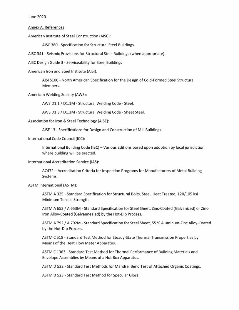
American Institute of Steel Construction (AISC):
AISC 360 - Specification for Structural Steel Buildings.
AISC 341 - Seismic Provisions for Structural Steel Buildings (when appropriate).
AISC Design Guide 3 - Serviceability for Steel Buildings
American Iron and Steel Institute (AISI):
AISI S100 - North American Specification for the Design of Cold-Formed Steel Structural Members.
American Welding Society (AWS):
AWS D1.1 / D1.1M - Structural Welding Code - Steel.
AWS D1.3 / D1.3M - Structural Welding Code - Sheet Steel.
Association for Iron & Steel Technology (AISE):
AISE 13 - Specifications for Design and Construction of Mill Buildings.
International Code Council (ICC):
International Building Code (IBC) – Various Editions based upon adoption by local jurisdiction where building will be erected.
International Accreditation Service (IAS):
AC472 – Accreditation Criteria for Inspection Programs for Manufacturers of Metal Building Systems.
ASTM International (ASTM):
ASTM A 325 - Standard Specification for Structural Bolts, Steel, Heat Treated, 120/105 ksi Minimum Tensile Strength.
ASTM A 653 / A 653M - Standard Specification for Steel Sheet, Zinc-Coated (Galvanized) or Zinc-Iron Alloy-Coated (Galvannealed) by the Hot-Dip Process.
ASTM A 792 / A 792M - Standard Specification for Steel Sheet, 55 % Aluminum-Zinc Alloy-Coated by the Hot-Dip Process.
ASTM C 518 - Standard Test Method for Steady-State Thermal Transmission Properties by Means of the Heat Flow Meter Apparatus.
ASTM C 1363 - Standard Test Method for Thermal Performance of Building Materials and Envelope Assemblies by Means of a Hot Box Apparatus.
ASTM D 522 - Standard Test Methods for Mandrel Bend Test of Attached Organic Coatings.
ASTM D 523 - Standard Test Method for Specular Gloss.
June 2020
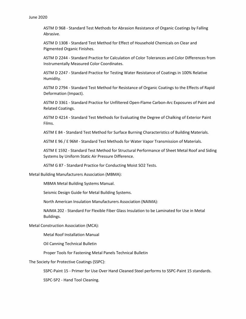
ASTM D 968 - Standard Test Methods for Abrasion Resistance of Organic Coatings by Falling Abrasive.
ASTM D 1308 - Standard Test Method for Effect of Household Chemicals on Clear and Pigmented Organic Finishes.
ASTM D 2244 - Standard Practice for Calculation of Color Tolerances and Color Differences from Instrumentally Measured Color Coordinates.
ASTM D 2247 - Standard Practice for Testing Water Resistance of Coatings in 100% Relative Humidity.
ASTM D 2794 - Standard Test Method for Resistance of Organic Coatings to the Effects of Rapid Deformation (Impact).
ASTM D 3361 - Standard Practice for Unfiltered Open-Flame Carbon-Arc Exposures of Paint and Related Coatings.
ASTM D 4214 - Standard Test Methods for Evaluating the Degree of Chalking of Exterior Paint Films.
ASTM E 84 - Standard Test Method for Surface Burning Characteristics of Building Materials.
ASTM E 96 / E 96M - Standard Test Methods for Water Vapor Transmission of Materials.
ASTM E 1592 - Standard Test Method for Structural Performance of Sheet Metal Roof and Siding Systems by Uniform Static Air Pressure Difference.
ASTM G 87 - Standard Practice for Conducting Moist SO2 Tests.
Metal Building Manufacturers Association (MBMA):
MBMA Metal Building Systems Manual.
Seismic Design Guide for Metal Building Systems.
North American Insulation Manufacturers Association (NAIMA):
NAIMA 202 - Standard For Flexible Fiber Glass Insulation to be Laminated for Use in Metal Buildings.
Metal Construction Association (MCA):
Metal Roof Installation Manual
Oil Canning Technical Bulletin
Proper Tools for Fastening Metal Panels Technical Bulletin
The Society for Protective Coatings (SSPC):
SSPC-Paint 15 - Primer for Use Over Hand Cleaned Steel performs to SSPC-Paint 15 standards.
SSPC-SP2 - Hand Tool Cleaning.