Embed Size (px)
Citation preview

2525 Palmer Street, Suite 2, Missoula, MT 59808
Tel 406.543.3045 Fax 406.543.3088 www.tetratech.com
June 16, 2014 Mr. Christopher Anderson, PE, LEED AP 3203 Russell Street Missoula, Montana 59801 SUBJECT: Geotechnical Investigation Lolo to Missoula Bicycle-Pedestrian Trail
Missoula County, Montana Project No. 114-570781.100 Dear Mr. Anderson: At your request, we have performed a geotechnical investigation of the subsurface soil conditions at the site of the proposed Lolo to Missoula Bicycle-Pedestrian Trail in Missoula County, Montana. Also as part of this project, we have also performed a foundation design for the proposed bicycle-pedestrian bridge crossing the Bitterroot River just west of Reserve Street, on Highway 93. This report presents our investigations, the results of our findings, and our foundation design recommendations for the trail system and associated retaining walls. Although we presented bridge foundation design recommendations in this report, we understand the bridge alternative has been eliminated from the project. It is important that we provide consultation and review during the design phase, and field observation and testing services during construction, to ensure complete implementation of the geotechnical design recommendations. If you have any questions, please contact me or Marco Fellin at 406-543-3045. Respectfully submitted, TETRA TECH
Marco Fellin, P.E. Project Geotechnical Engineer
Tetra Tech June 2014 1
TABLE OF CONTENTS
PROPOSED CONSTRUCTION .................................................................................................. 2
PURPOSE AND SCOPE OF STUDY ......................................................................................... 2
FIELD EXPLORATION ............................................................................................................... 2
LABORATORY TESTING .......................................................................................................... 3
SEISMIC DESIGN CRITERIA ..................................................................................................... 4
SUBSURFACE CONDITIONS .................................................................................................... 4
ASPHALT, BASE AND SUBBASE .................................................................................. 4
FILL……………………………………………………………………………………….5
NATIVE SAND AND GRAVEL ......................................................................................... 5
GROUNDWATER............................................................................................................ 6
ENGINEERING ANALYSIS AND RECOMMENDATIONS .......................................................... 6
RETAINING WALLS ........................................................................................................ 6
Slope Stability Analyses .................................................................................................. 8
Site Grading for Retaining Walls .................................................................................... 10
CONSTRUCTION CONSIDERATIONS ......................................................................... 12
BRIDGE FOUNDATION DESIGN .................................................................................. 12
TRAIL PAVEMENT SECTION DESIGN ........................................................................ 16
CONTINUING SERVICES ........................................................................................................ 18
LIMITATIONS ........................................................................................................................... 19
APPENDIX Important Information About Your Geotechnical Engineering Report (Published by ASFE)
Explanation of Abbreviations and Descriptive Terms
Classification of Soils for Engineering Purposes
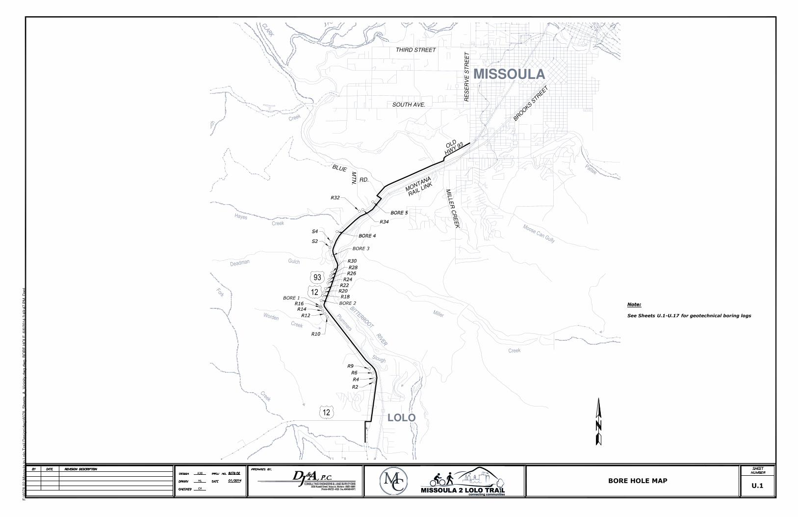
Appendix A - Vicinity Map - Sheet U.1 – Locations of Exploration Borings Appendix B - Logs and Lab Testing Data:
Figures 1 and 24 – Logs of Exploratory Borings Figures 25 through 55 – Laboratory Test Data
Appendix C - Proposed Bicycle-Pedestrian Bridge Plan Sheet - HDR As-Built Bridge Plans with Geotechnical Boring and Proposed Bridge Locations Figures 1 through 4 - Drilled Shaft Capacity Estimates for Piers and Abutments
Appendix D – Project and Retaining Wall Location Photographs
Appendix E - Trail Typical Sections
Appendix F - Project Special Provisions:
- Retaining Wall Specials (3 total)
- Asphalt Surface Course Special and Base Course Stabilization Special
Appendix G - Slope Stability Figure
Tetra Tech June 2014 2
PROPOSED CONSTRUCTION
The project consists of constructing a new paved bicycle-pedestrian path on the existing MDT Right-of-Way between Highway 93 and the MRL rail line. The path corridor begins at Bird Lane near Lolo, and continues north on the east side of Highway 93 to Blue Mountain Road in Missoula. The path will be constructed on varying topography; from relatively level terrain to moderately steep slopes. At this time, it has been estimated that approximately 6,800 linear feet of retaining walls will be required where the trail system traverses across existing slopes. Wall sections could range from 200 to 1,600 feet long and 4 to 8 feet in height on the respective fill sections. There are currently 5 proposed continuous wall sections, with another wall section proposed on an alternate alignment. The Montana Department of Transportation has a stockpile of Recycled Asphalt Pavement (RAP) available to use for the trail pavement section; consisting of approximately 7,000 cubic yards of millings. The RAP pile is located at the MDT storage yard SW of the intersection of Reserve Street and West Broadway in Missoula. We understand the millings were generated from Interstate 90 milling projects near Alberton. As part of the proposed trail system, a bicycle-pedestrian bridge structure was planned to be constructed over the Bitterroot River adjacent to the existing Highway 93 bridge near Missoula. The new structure was proposed to have three spans, with each bent consisting of a single column supported on a drilled shaft foundation. The bridge option has currently been eliminated from the project, and the proposed plan is to widen the existing Highway 93 bridge sidewalk on the north spans to accommodate bicycles and pedestrians. We have included the bridge design information with this report in the event the bridge option is considered in the future.
PURPOSE AND SCOPE OF STUDY
The purpose of our geotechnical investigations were to, 1) obtain data on subsurface conditions at the retaining wall locations along the proposed trail alignment, 2) evaluate the RAP source for potential use in the trail pavement section, either in the base or surfacing course, and 3) design drilled shaft foundations for the pedestrian bridge. Following is a discussion of the field investigations, subsoils encountered, and geotechnical recommendations.
FIELD EXPLORATION
Tetra Tech conducted an initial field exploration program in January 2014 consisting of five exploration borings to obtain information on subgrade soil conditions along the proposed trail site between Lolo and Missoula (see Sheet U.1, Appendix A, prepared by DJ&A). The five borings were drilled at locations accessible to the drill rig where traffic control was not necessary. Tetra Tech also visited the RAP storage site in January 2014 to obtain samples for laboratory testing. A subsequent field investigation was performed in May 2014, consisting of drilling 19 additional borings within the footprints of the proposed retaining wall locations. The borings were drilled
Tetra Tech June 2014 3
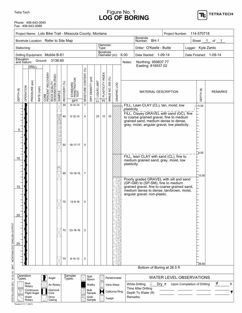
through the asphalt pavement section adjacent to the guardrail in the proposed retaining wall sections. The approximate locations of the 19 borings are shown on Sheet U.1, Appendix A. The horizontal and vertical coordinates of all borings were surveyed by DJ&A. The elevation, northing, easting and station of each boring are included on the logs of the borings in Appendix B. Photos of the initial drilling locations, the RAP stockpile, and the proposed retaining wall locations are included in Appendix D. Samples of the subsurface materials were taken with a 2-inch outside diameter (O.D.) split-spoon sampler driven into the various strata using a 140-pound hammer falling 30 inches. The number of blows required to advance the sampler each successive 6-inch increment was recorded; the total number of blows required to advance the sampler the second and third 6-inch increments is the penetration resistance (N value). The 2-inch O.D. sampler is the standard penetration test described by ASTM Method D1586. Penetration resistance values indicate the relative density or consistency of the soils. Disturbed bulk samples were obtained from the auger cuttings in the upper 10 feet of the borings. Depths at which the samples were taken and the penetration resistance values are shown on the logs of exploration borings, Figures 1 through 24. Samples obtained during the field investigations were tested in Tetra Tech’s laboratory to determine the physical and engineering characteristics of the on-site soils. This report summarizes the field data and presents conclusions and recommendations for design and construction of the trail and bridge foundations based on the proposed construction and subsurface conditions encountered. The report also includes design parameters and geotechnical engineering considerations related to retaining wall construction.
LABORATORY TESTING
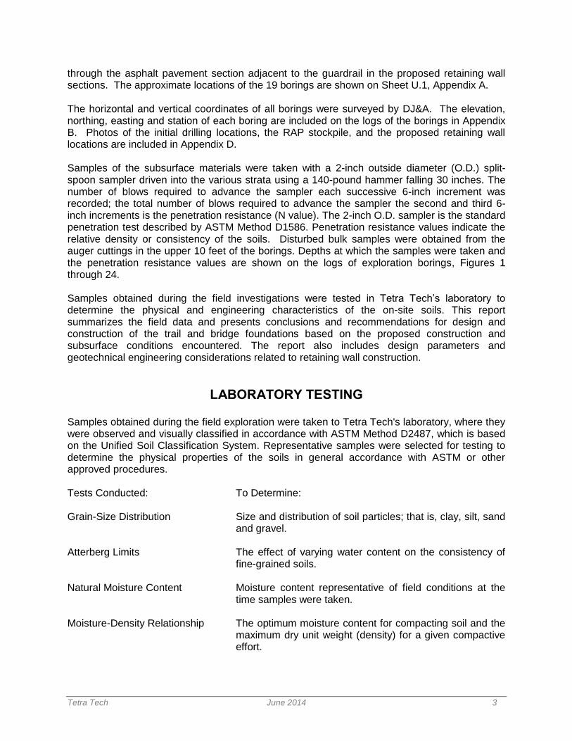
Samples obtained during the field exploration were taken to Tetra Tech's laboratory, where they were observed and visually classified in accordance with ASTM Method D2487, which is based on the Unified Soil Classification System. Representative samples were selected for testing to determine the physical properties of the soils in general accordance with ASTM or other approved procedures. Tests Conducted: To Determine: Grain-Size Distribution Size and distribution of soil particles; that is, clay, silt, sand
and gravel. Atterberg Limits The effect of varying water content on the consistency of
fine-grained soils. Natural Moisture Content Moisture content representative of field conditions at the
time samples were taken. Moisture-Density Relationship The optimum moisture content for compacting soil and the
maximum dry unit weight (density) for a given compactive effort.
Tetra Tech June 2014 4
Resistivity and pH The combination of these characteristics determines the potential of soil to corrode metal.
Sulfate Content Potential of soils to deteriorate normal strength concrete. Laboratory test results are presented graphically on Figures 25 through 55 in the Appendix. These data, along with the field information, were used to prepare the exploration boring logs, Figures 1 through 24.
SEISMIC DESIGN CRITERIA The seismic Peak Ground Acceleration (PGA) was determined to by 0.142g (using 2009
AASHTO Guide Specifications for LRFD Seismic Bridge Design and USGS hazard data for the
Missoula area). The methods of IBC 2009 require that the properties of the soil at the proposed
site be classified as one of several site classes. The seismic design parameters for this site
include a seismic zone soil profile type of (D), in accordance with the above referenced
standard. Site Class D corresponds to a stiff soil profile having an undrained shear strength of
1,000 to 2,000 psf and standard penetration resistance values averaging 15 to 50 blows per foot
in the upper 100 feet. We have based this classification on the laboratory test data and
exploration boring information.
SUBSURFACE CONDITIONS
Access limitations required that all geotechnical borings within the retaining wall footprints be drilled from the existing highway such that subsurface profiles penetrate through the existing pavement section. The subsurface profile encountered in the 19 borings drilled within the station limits of the retaining walls generally consists of an asphalt, base, and subbase section overlying approximately 5 to 21 feet of predominately sand and gravel road embankment fill overlying native sand and gravel to the maximum depth explored of 35.5 feet. The boring logs should be referenced for complete descriptions of the soil types and their estimated depths. A characterization of the subsurface profile normally includes grouping soils with similar physical and engineering properties into a number of distinct layers. The representative subsurface layers at the site are presented below, starting at the ground surface.
ASPHALT, BASE AND SUBBASE The existing asphalt layer ranged in thickness from 0.5 to 1 foot. The granular layer
immediately beneath the pavement surfacing consisted of approximately 1.25 to 5.5 feet of
poorly graded gravel and sand. It was difficult in the field to determine if a separate base and
subbase layer existed, since in most cases the processed granular material beneath the
pavement was relatively homogenous for the depth listed on the logs. The base/subbase layer
was generally; medium to very dense, subrounded to angular, slightly moist based on moisture
contents averaging approximately 5 percent, and brown.
Tetra Tech June 2014 5
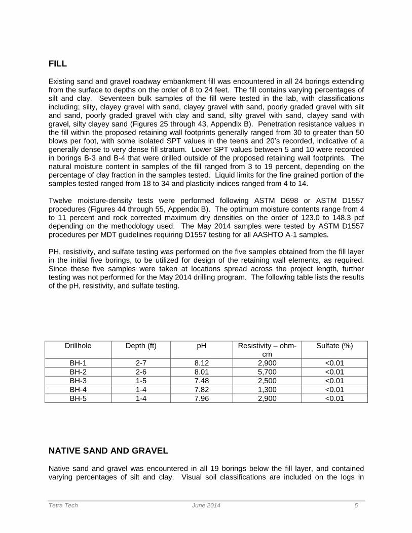
FILL Existing sand and gravel roadway embankment fill was encountered in all 24 borings extending from the surface to depths on the order of 8 to 24 feet. The fill contains varying percentages of silt and clay. Seventeen bulk samples of the fill were tested in the lab, with classifications including; silty, clayey gravel with sand, clayey gravel with sand, poorly graded gravel with silt and sand, poorly graded gravel with clay and sand, silty gravel with sand, clayey sand with gravel, silty clayey sand (Figures 25 through 43, Appendix B). Penetration resistance values in the fill within the proposed retaining wall footprints generally ranged from 30 to greater than 50 blows per foot, with some isolated SPT values in the teens and 20’s recorded, indicative of a generally dense to very dense fill stratum. Lower SPT values between 5 and 10 were recorded in borings B-3 and B-4 that were drilled outside of the proposed retaining wall footprints. The natural moisture content in samples of the fill ranged from 3 to 19 percent, depending on the percentage of clay fraction in the samples tested. Liquid limits for the fine grained portion of the samples tested ranged from 18 to 34 and plasticity indices ranged from 4 to 14. Twelve moisture-density tests were performed following ASTM D698 or ASTM D1557 procedures (Figures 44 through 55, Appendix B). The optimum moisture contents range from 4 to 11 percent and rock corrected maximum dry densities on the order of 123.0 to 148.3 pcf depending on the methodology used. The May 2014 samples were tested by ASTM D1557 procedures per MDT guidelines requiring D1557 testing for all AASHTO A-1 samples. PH, resistivity, and sulfate testing was performed on the five samples obtained from the fill layer in the initial five borings, to be utilized for design of the retaining wall elements, as required. Since these five samples were taken at locations spread across the project length, further testing was not performed for the May 2014 drilling program. The following table lists the results of the pH, resistivity, and sulfate testing.
Drillhole Depth (ft) pH Resistivity – ohm-cm
Sulfate (%)
BH-1 2-7 8.12 2,900 <0.01
BH-2 2-6 8.01 5,700 <0.01
BH-3 1-5 7.48 2,500 <0.01
BH-4 1-4 7.82 1,300 <0.01
BH-5 1-4 7.96 2,900 <0.01
NATIVE SAND AND GRAVEL Native sand and gravel was encountered in all 19 borings below the fill layer, and contained varying percentages of silt and clay. Visual soil classifications are included on the logs in
Tetra Tech June 2014 6
Appendix B. Penetration resistance (SPT) values in the native layer generally ranged from 21 to greater than 50 blows per foot, which is indicative of a medium dense to very dense soil stratum. The natural moisture content in samples tested ranged from 2 to 14 percent. Boring BH-5 had SPT values ranging from 4 to 5 below the water table in BH-5, indicating a very loose to loose layer, and moisture contents as high as 33 percent.
GROUNDWATER Subsurface water was encountered in Boring BH-5 at a depth of approximately 12.5 feet below the ground surface at the time of drilling (January, 2014). Boring BH-5 was drilled during the initial drilling program, and does not fall within the limits of any of the current retaining wall station limits. The ground elevation of BH-5 is approximately 30 to 60 feet below the other four borings drilled, and is closer to the elevation of the Bitterroot River. Groundwater depths will generally vary depending on the time of year. Numerous factors contribute to groundwater fluctuations, and evaluation of such factors is beyond the scope of this report.
ENGINEERING ANALYSIS AND RECOMMENDATIONS Following is a discussion of analyses, recommendations, and construction considerations for; 1) retaining walls, 2) slopes, 3) bridge foundation design, 4) trail pavement section.
RETAINING WALLS
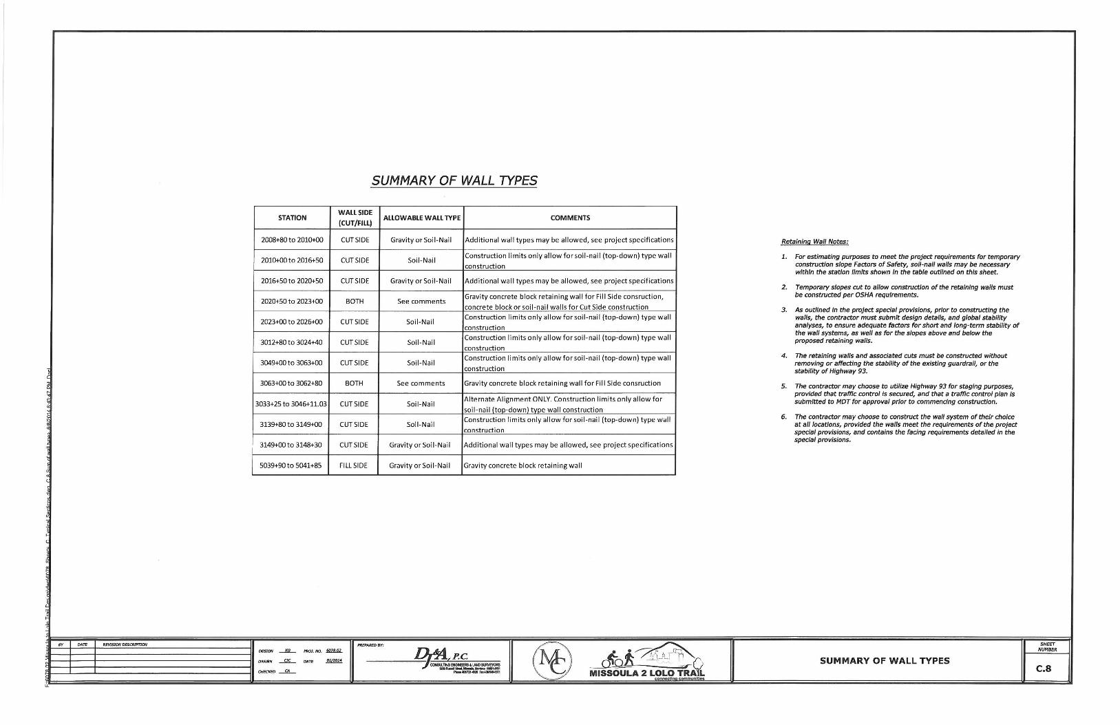
Retaining walls are being proposed along approximately 6,800 lineal feet of the trail alignment, and are predominately located in project Section 3 shown in Appendix A. The majority of the retaining walls will be constructed on the existing slope east of the Highway 93 guardrail, with proposed wall heights predominately on the order of 4 to 8 feet. Slopes on the order of 1.5(Horizontal):1(Vertical) are proposed at some locations extending from the back of guardrail to the top of wall. Several of the wall sections are in fill sections, and are shorter in length and height. The following Sheet C.8 from the 95% plan sheets lists the summary of wall station limits and allowable wall types.
Tetra Tech June 2014 8
Depending on the height of retained soils and proximity to the guardrail, several wall types may be feasible, including; soil nail walls, gravity walls, MSE walls. Three retaining wall special provisions are included in Appendix F, outlining the design and construction requirements for all walls on the project, including; 1) General Retaining Wall Special Provision, 2) Soil Nail Wall Special Provision, and 3) Gravity and MSE Wall Special Provision. The contractor chosen for the project is free to design and construct the wall types of their choice, provided all the requirements of the special provisions are met. Constructability of the walls, including temporary slope stability, are a significant concerns on this project. Tetra Tech performed a global slope stability analyses of the proposed walls sections and slopes, and analyzed several cases, including; 1) temporary construction slopes, and 2) final constructed slopes. The ‘General Retaining Wall Special Provision’ includes estimated station limits where soil nail walls will likely be required to maintain slope stability during construction. Following is a discussion the slope stability performed for the walls, site grading, and other construction and design considerations.
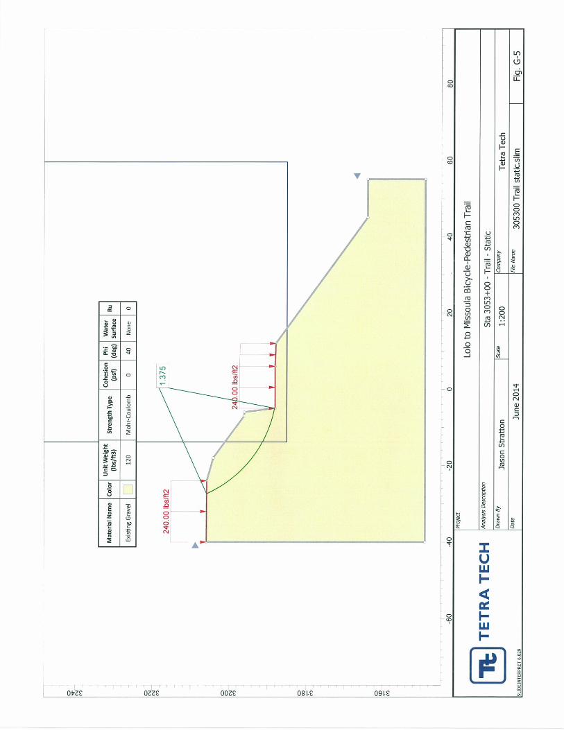
Slope Stability Analyses Slope stability analyses were conducted using Slide version 6.029 by Rocscience, Inc. Slide
conducts two-dimensional limit equilibrium slope stability analyses. For this project, the Bishop
simplified and Janbu simplified methods were both utilized for all analyses with the lowest
calculated factor of safety from each of these methods reported.
Highway loading is typically modelled as a uniform load equivalent to two feet of soil. For this
project, this is equivalent to 240 pounds per square foot (psf) uniformly applied over the highway
area. The trail will not be subject to highway loading but will be subject to significant loading
during construction. Therefore, the 240 psf uniform load was also applied to the trail area in the
stability models.
Existing Slope Analyses
The stability modelling was initially calibrated by back-analysis of the existing slopes. For the
purposes of determining shear strength for the existing subsurface materials, a simplified model
of the existing ground surface was analyzed. Station 3097+00 represents the tallest and
steepest portion of the existing highway embankment slopes that will be modified for the trail
construction (approximate 50-foot height at 1.5:1 slopes). The subsurface material was
assumed to be gravel fill with zero cohesion. For a zero cohesion material, the angle of internal
friction must be greater than the existing slope angle (34 degrees) for the slope stability factor of
safety to be greater than 1.0.
As discussed under ‘Subsurface Conditions’, penetration resistance values in the fill within the
proposed retaining wall footprints generally ranged from 30 to greater than 50 blows per foot,
with some isolated SPT values in the teens and 20’s recorded, indicative of a generally dense to
very dense fill stratum. Lower SPT values between 5 and 10 were recorded in borings B-3 and
Tetra Tech June 2014 9
B-4 that were drilled outside of the proposed retaining wall footprints. The angularity of the
gravel fill was generally observed to be subrounded to subangular, with some zones being more
subangular to angular. Published correlations between soil friction angle and blow counts for
medium to very dense gravel and sand mixtures with varying amounts of silt and clay indicate
friction angles on the order of 34 to 48, depending on; the relative density, the percentage of silt
and clay, and the angularity of the gravel fraction. Based on the engineering properties of the
soils encountered in the subsurface investigation, we have assumed the in-place gravel and
sand fill layer has a minimum friction angle on the order of 36 degrees.
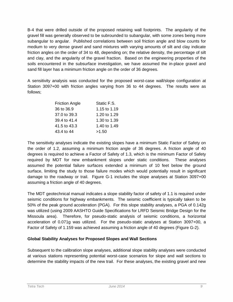
A sensitivity analysis was conducted for the proposed worst-case wall/slope configuration at
Station 3097+00 with friction angles varying from 36 to 44 degrees. The results were as
follows;
Friction Angle Static F.S.
36 to 36.9 1.15 to 1.19
37.0 to 39.3 1.20 to 1.29
39.4 to 41.4 1.30 to 1.39
41.5 to 43.3 1.40 to 1.49
43.4 to 44 >1.50
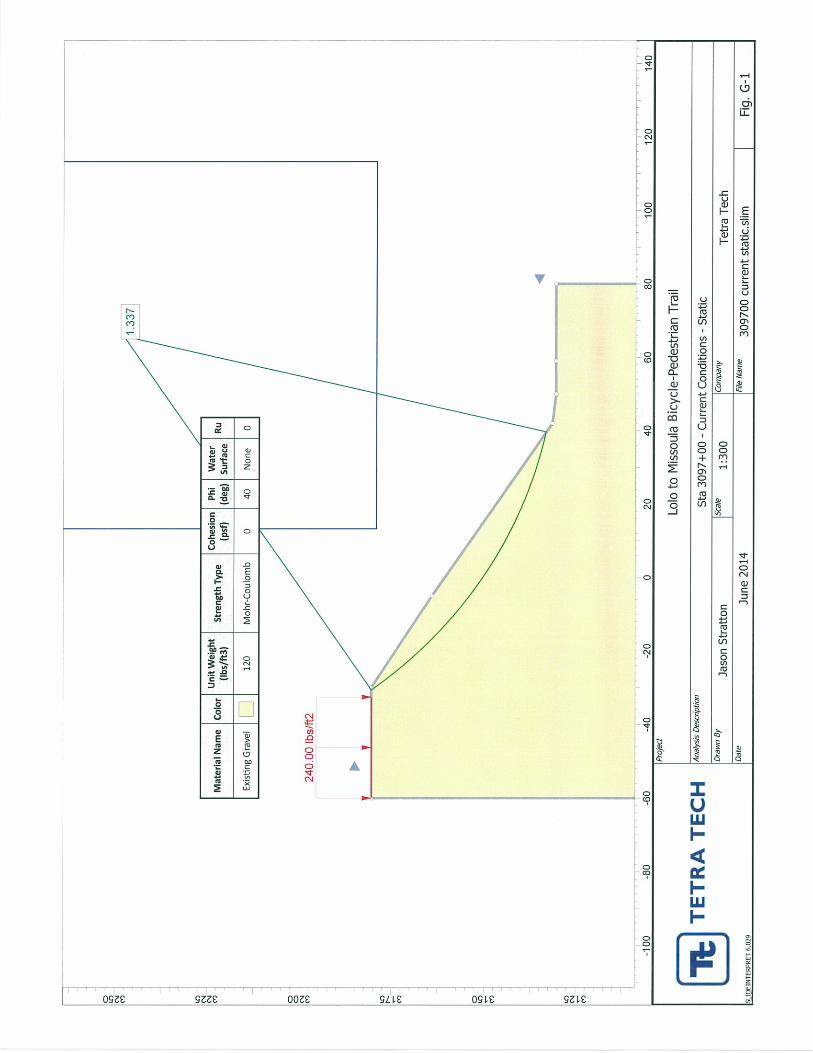
The sensitivity analyses indicate the existing slopes have a minimum Static Factor of Safety on
the order of 1.2, assuming a minimum friction angle of 36 degrees. A friction angle of 40
degrees is required to achieve a Factor of Safety of 1.3, which is the minimum Factor of Safety
required by MDT for new embankment slopes under static conditions. These analyses
assumed the potential failure surfaces extended a minimum of 10 feet below the ground
surface, limiting the study to those failure modes which would potentially result in significant
damage to the roadway or trail. Figure G-1 includes the slope analyses at Station 3097+00
assuming a friction angle of 40 degrees.
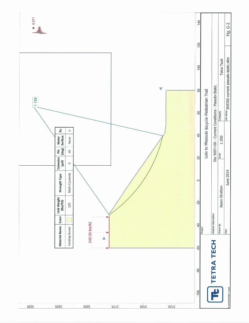
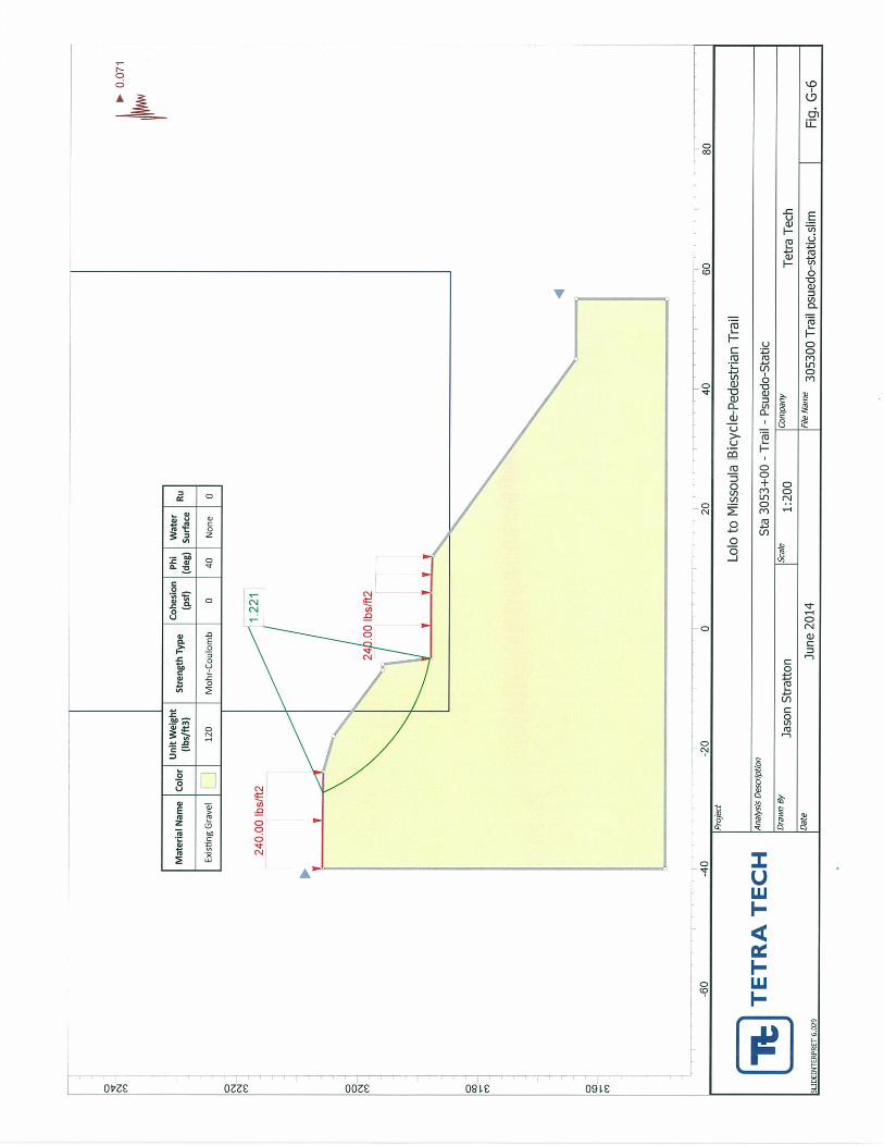
The MDT geotechnical manual indicates a slope stability factor of safety of 1.1 is required under
seismic conditions for highway embankments. The seismic coefficient is typically taken to be
50% of the peak ground acceleration (PGA). For this slope stability analyses, a PGA of 0.142g
was utilized (using 2009 AASHTO Guide Specifications for LRFD Seismic Bridge Design for the
Missoula area). Therefore, for pseudo-static analysis of seismic conditions, a horizontal
acceleration of 0.071g was utilized. For the pseudo-static analyses at Station 3097+00, a
Factor of Safety of 1.159 was achieved assuming a friction angle of 40 degrees (Figure G-2).
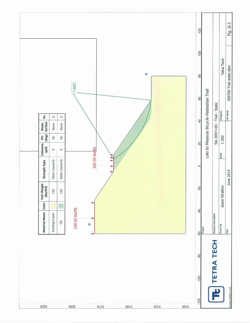
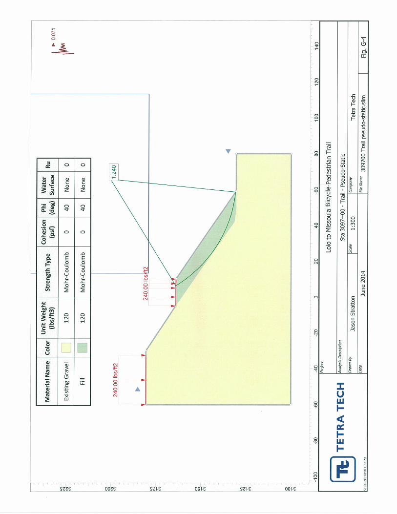
Global Stability Analyses for Proposed Slopes and Wall Sections
Subsequent to the calibration slope analyses, additional slope stability analyses were conducted
at various stations representing potential worst-case scenarios for slope and wall sections to
determine the stability impacts of the new trail. For these analyses, the existing gravel and new
Tetra Tech June 2014 10
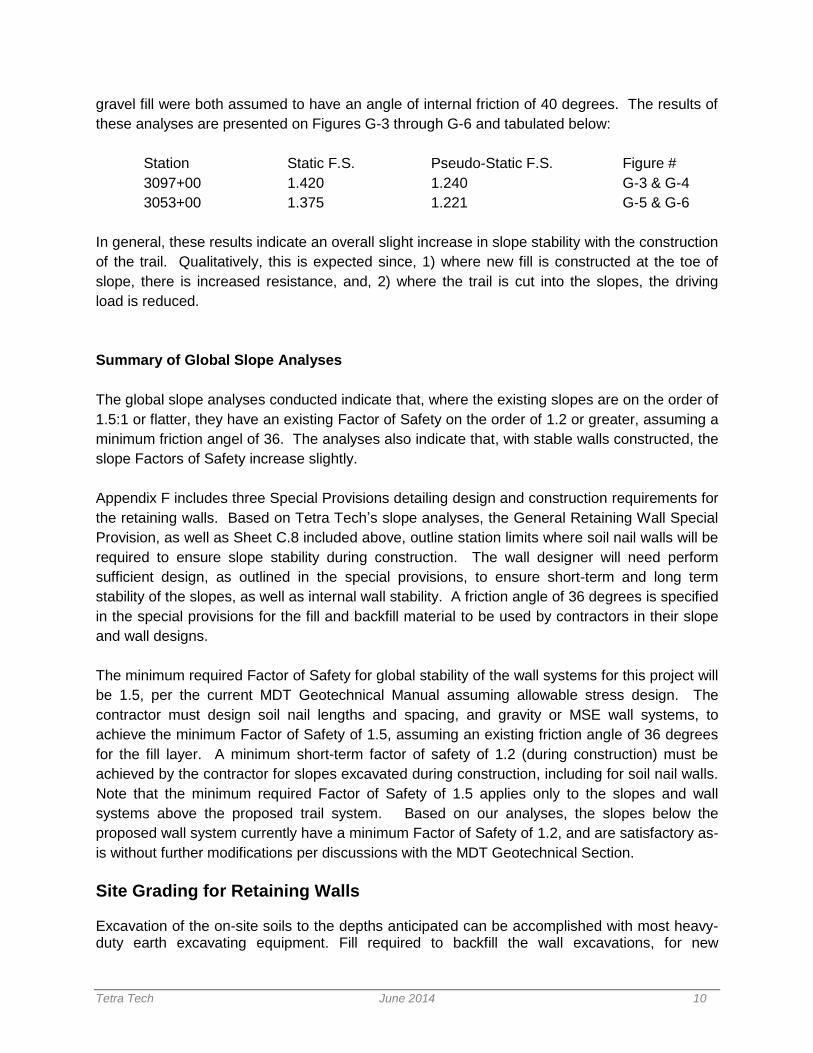
gravel fill were both assumed to have an angle of internal friction of 40 degrees. The results of
these analyses are presented on Figures G-3 through G-6 and tabulated below:
Station Static F.S. Pseudo-Static F.S. Figure #
3097+00 1.420 1.240 G-3 & G-4
3053+00 1.375 1.221 G-5 & G-6
In general, these results indicate an overall slight increase in slope stability with the construction
of the trail. Qualitatively, this is expected since, 1) where new fill is constructed at the toe of
slope, there is increased resistance, and, 2) where the trail is cut into the slopes, the driving
load is reduced.
Summary of Global Slope Analyses
The global slope analyses conducted indicate that, where the existing slopes are on the order of
1.5:1 or flatter, they have an existing Factor of Safety on the order of 1.2 or greater, assuming a
minimum friction angel of 36. The analyses also indicate that, with stable walls constructed, the
slope Factors of Safety increase slightly.
Appendix F includes three Special Provisions detailing design and construction requirements for
the retaining walls. Based on Tetra Tech’s slope analyses, the General Retaining Wall Special
Provision, as well as Sheet C.8 included above, outline station limits where soil nail walls will be
required to ensure slope stability during construction. The wall designer will need perform
sufficient design, as outlined in the special provisions, to ensure short-term and long term
stability of the slopes, as well as internal wall stability. A friction angle of 36 degrees is specified
in the special provisions for the fill and backfill material to be used by contractors in their slope
and wall designs.
The minimum required Factor of Safety for global stability of the wall systems for this project will
be 1.5, per the current MDT Geotechnical Manual assuming allowable stress design. The
contractor must design soil nail lengths and spacing, and gravity or MSE wall systems, to
achieve the minimum Factor of Safety of 1.5, assuming an existing friction angle of 36 degrees
for the fill layer. A minimum short-term factor of safety of 1.2 (during construction) must be
achieved by the contractor for slopes excavated during construction, including for soil nail walls.
Note that the minimum required Factor of Safety of 1.5 applies only to the slopes and wall
systems above the proposed trail system. Based on our analyses, the slopes below the
proposed wall system currently have a minimum Factor of Safety of 1.2, and are satisfactory as-
is without further modifications per discussions with the MDT Geotechnical Section.
Site Grading for Retaining Walls Excavation of the on-site soils to the depths anticipated can be accomplished with most heavy-duty earth excavating equipment. Fill required to backfill the wall excavations, for new
Tetra Tech June 2014 11
embankment construction, or for general site grading should consist of the on-site sand and gravel fill or engineered gravel fill meeting the grading and compaction requirements listed below. Data from the borings indicates that groundwater should not be encountered for wall excavations at Elevation 3,140 or higher; however, groundwater could be encountered in excavations near BH-5, or at the wall sections where the existing ground elevation is at or below 3,140.00 feet, depending on the time of year of construction. The design and construction criteria presented below should be observed for site preparation purposes; construction details should be considered when preparing project documents. The design and construction criteria presented below should be observed for retaining walls, and are included in the project Special Provisions. 1. The base of walls should bear on existing sand and gravel fill, native sand and gravel, or
engineered gravel fill, and designed per LRFD specifications. 2. Retaining walls should be designed for internal stability per current LRFD specifications.
3. If silt or clay fill material is encountered at the footing elevation of walls, a minimum of 2
feet of should be subexcavated and replaced with a minimum of 2 feet of engineered gravel fill.
4. Following excavation for the wall footings and compaction, we recommend proofrolling the footing subgrade with a heavy wheeled truck to identify soft areas prior to constructing the wall section. Where soft areas are encountered at subgrade elevation, a minimum of 2 feet should be subexcavated and replaced with a minimum of 2 feet of engineered gravel fill.
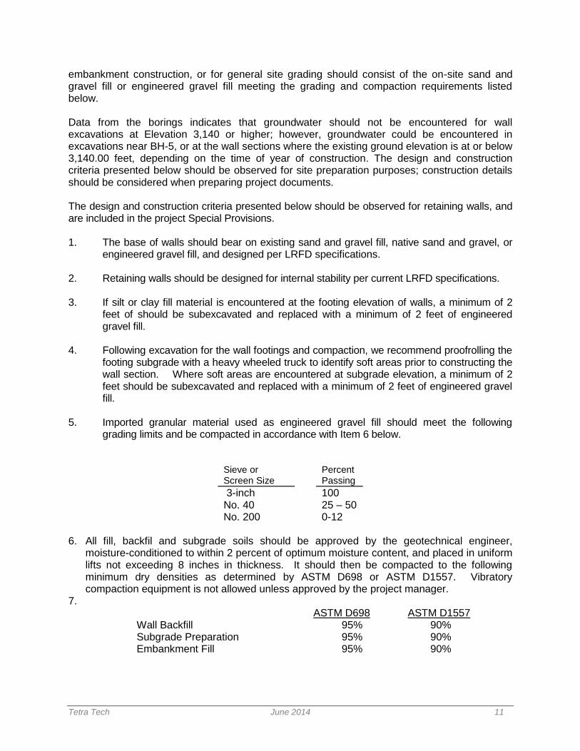
5. Imported granular material used as engineered gravel fill should meet the following grading limits and be compacted in accordance with Item 6 below.
Sieve or Screen Size
Percent Passing
3-inch 100 No. 40 25 – 50 No. 200 0-12
6. All fill, backfil and subgrade soils should be approved by the geotechnical engineer,
moisture-conditioned to within 2 percent of optimum moisture content, and placed in uniform lifts not exceeding 8 inches in thickness. It should then be compacted to the following minimum dry densities as determined by ASTM D698 or ASTM D1557. Vibratory compaction equipment is not allowed unless approved by the project manager.
7. ASTM D698 ASTM D1557 Wall Backfill 95% 90% Subgrade Preparation 95% 90% Embankment Fill 95% 90%
Tetra Tech June 2014 12
8. The existing sand and gravel fill and natural sand and gravel are suitable for use as backfill
and embankment fill, provided they meet the corrosion requirements of the each material manufacturer, are moisture-conditioned and compacted in accordance with Item 7 above. Silt or clay fill are not suitable for backfill or fill on this project, and should be exported off site.
9. The contractor is responsible for providing safe working conditions in connection with excavations for walls adjacent to Highway 93. Temporary construction excavations, which workers will enter, will be governed by OSHA guideline 1926.6542 Appendix B to subpart P. For planning purposes, subsoils encountered in the exploration borings classify as Type C. The wall excavations must be checked for global stability to ensure they have an adequate Factor of Safety during construction. The global stability analyses must include heavy truck traffic loads.
10. Temporary and permanent wall sections must be designed for heavy traffic surcharge loads
on Highway 93 adjacent to the guardrail, as well as the 1.5:1 slopes above the wall.
11. All walls should be constructed in accordance with the manufacturer/supplier recommendations.
CONSTRUCTION CONSIDERATIONS Fill slopes up to 15 to 20 feet high are proposed at some locations, with the toe footprint of the fill extending on the order of 5 to 20 feet horizontally adjacent to the existing toe of slope. The following items should be considered during design of slopes, and during preparation of the project plans and documents;
1. The MDT Standard Specifications for Road and Bridge Construction, or the Montana Public Works Specifications, should be referenced on the plan sheets for slope construction, including; subgrade preparation prior to beginning fill placement, benching of existing slopes prior to and during fill placement, compaction of fill, and seeding as required.
2. Benching the existing slopes is critical to ensure the stability of the fill slope following
construction. We recommend that a note be placed on all plan sheets requiring the slopes to be benched a minimum of 4-feet wide, with the 4-foot bench required with each lift of fill placed.
BRIDGE FOUNDATION DESIGN
The bridge alternative for this project has currently been eliminated. Following is a discussion of the bridge foundation analysis and design that was completed prior to elimination of the bridge alternative from the project. As part of the proposed Lolo to Missoula trail system, a bicycle-pedestrian bridge structure is planned to be constructed over the Bitterroot River adjacent to the existing bridge. The

Tetra Tech June 2014 13
approximate location and bridge layout is included on the plan sheet in Appendix C provided by HDR. The proposed structure will be on the order of 15 feet in width, and will be offset downstream from the existing southbound bridge structure approximately 5 to 10 feet from the edge of the existing bridge. The new structure is proposed to have three spans, with each bent consisting of a single column supported on a drilled shaft foundation. Drilled shafts will be utilized to avoid coffer dam construction typical for pile foundations in a river environment. Four geotechnical borings were drilled for the original bridge structure. The locations have been noted on the attached As-built Drawing No. 6527A (in yellow and green highlight) in Appendix C, and the logs of the borings are shown on Drawing No. 6528A, Appendix C. The depths of the four borings were on the order of 70 to 90 feet below the native ground. Two of the borings were drilled close to the existing median centerline, and two were drilled 133 to 172 feet left of median centerline. All four borings encompass the footprint of the proposed structure. The following sections discuss the bridge foundation design and construction considerations.
Drilled Shaft Design and Analyses The foundation design alternative currently being evaluated by HDR will consist of one 7 to 8-foot diameter drilled shaft at each river pier, and one smaller diameter drilled shaft at each abutment. Design loads have not been finalized as of this report submittal. Preliminary information obtained from HDR indicates design loads per shaft could be on the order of 1,200 kips per large-diameter shaft. Hydraulic information provided by HDR indicates that the 100-year flood level will cause up to 15 feet of pier scour, and no contraction scour. The specific design manuals utilized for the bridge and foundation design are, 1) AASHTO LRFD Bridge Design Specifications (2012), 2) 2011 AASHTO Guide Specifications for LRFD Seismic Bridge Design, 2nd Edition, 3) FHWA Publication No. IF-99-025, Drilled Shafts – Construction Procedures and Design Methods, August 1999. Axial and Lateral Load Analysis Ultimate axial drilled shaft capacities have been calculated based on methodologies presented in FHWA Publication, ‘Drilled Shafts – Construction Procedures and Design Methods’, August 1999, and computer program SHAFT 6.0, A Program for the Study of Drilled Shafts Under Axial Loads (2012 with recent 2014 updates). The following table lists the soil parameters utilized in the axial analyses, and to be used for the lateral shaft design. We have assumed that HDR will perform the lateral shaft analyses once the final shaft configuration and diameters have been finalized.
Tetra Tech June 2014 14
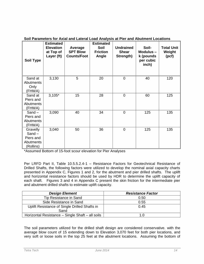
Soil Parameters for Axial and Lateral Load Analysis at Pier and Abutment Locations
Soil Type
Estimated Elevation at Top of Layer (ft)
Average
SPT Blow Counts/Foot
Estimated Soil
Friction Angle
Undrained
Shear Strength)
Soil-
Modulus – k (pounds per cubic
inch)
Total Unit
Weight (pcf)
Sand at Abutments
Only (FHWA)
3,130 5 20 0 40 120
Sand at Piers and Abutments
(FHWA)
3,105* 15 28 0 60 125
Sand – Piers and Abutments
(FHWA)
3,090 40 34 0 125 135
Gravelly Sand –
Piers and Abutments (Rollins)
3,040 50 36 0 125 135
*Assumed Bottom of 15-foot scour elevation for Pier Analyses Per LRFD Part II, Table 10.5.5.2.4-1 – Resistance Factors for Geotechnical Resistance of Drilled Shafts, the following factors were utilized to develop the nominal axial capacity charts presented in Appendix C, Figures 1 and 2, for the abutment and pier drilled shafts. The uplift and horizontal resistance factors should be used by HDR to determine the uplift capacity of each shaft. Figures 3 and 4 in Appendix C present the skin friction for the intermediate pier and abutment drilled shafts to estimate uplift capacity.
Design Element Resistance Factor
Tip Resistance in Sand 0.50
Side Resistance in Sand 0.55
Uplift Resistance of Single Drilled Shafts in Sand
0.45
Horizontal Resistance – Single Shaft – all soils 1.0
The soil parameters utilized for the drilled shaft design are considered conservative. with the average blow count of 15 extending down to Elevation 3,070 feet for both pier locations, and very soft or loose soils in the top 25 feet at the abutment locations. Assuming the bottom of
Tetra Tech June 2014 15
scour elevation at the pier locations is 3,105 feet (15 feet of scour), the estimated shaft length is approximately 45 feet below scour elevation, or 60 feet below from Elevation 3,120 feet (bottom of shaft elevation of 3,060 feet) to achieve a total LRFD factored capacity 1,200 kips for 8-foot diameter piers. The bottom elevation of all four MDT borings ranged from 3,031 feet to 3,053 feet, and the bottom of shaft elevation is approximately one shaft diameter above the highest bottom of boring elevation of 3,053 feet. The deepest boring drilled by MDT extended to 3,031 feet.
Drilled Shaft Construction Construction of drilled shafts through the sand and gravel layers will require temporary casing to the bottom depth of each shaft excavation to maintain an open hole. The drilled shafts should be reinforced their entire length with a properly designed rebar cage for the structural loads anticipated. The design of the rebar cage should include installation of access tubes for nondestructive integrity testing of the concrete. Due to the presence of groundwater in the borings, placement of concrete by tremie or pumping methods is required. The design and construction criteria presented below should be observed for a drilled shaft foundation system. A drilled shaft special provision will be included in the project documents. 1. Structural loads should be supported on drilled shafts penetrating through the native sand
and gravel. The capacity charts included in Appendix C should be utilized by HDR to obtain shaft depths once loads are finalized.
2. Uplift due to structural loadings on the shafts can be resisted by using the LRFD Factored skin friction presented in Figures 3 and 4 in Appendix C, plus an allowance for shaft weight.
3. Removal of temporary casing could be difficult. Drilling contractors should anticipate the
need for special drilling and support equipment, including but not limited to; large 4-claw vibratory hammer, oscillator, or rotary casing advancer.
4. Concrete placed below the water table will require placement by tremie or pumping
methods. All pumping lines should have a minimum diameter of 4 inches and be constructed with watertight joints. A plug or similar device should be used to separate the concrete from the fluid in the hole until concreting begins. Concrete placement must not begin until the discharge orifice is at the shaft base.
5. Before the temporary casing is withdrawn, the level of fresh concrete in the casing must be
a minimum of 5 feet above the hydrostatic water level or the level of the drilling fluid, whichever is greater. As the casing is withdrawn, care must be exercised to maintain an adequate level of concrete within the casing so that the fluid trapped behind the casing is displaced upward and discharged at the ground surface without contaminating or displacing the shaft concrete.
6. Concrete used in the drilled shafts should have a slump on the order of 6 to 8 inches. 7. Shaft spacing should be a minimum of three diameters from center to center.
8. The minimum recommended shaft diameter is 3 feet.
Tetra Tech June 2014 16
9. Four access tubes should be installed evenly spaced around the reinforcing cage edge to
permit nondestructive cross-hole sonic log testing. Access tubes should be 2-inch nominal diameter with water-tight joints, and should be placed the full length of the reinforcement cage. The nondestructive testing should be performed at the owner’s discretion once the concrete has cured sufficiently to give consistent test readings.
10. The contractor performing the drilled shaft construction should have installed drilled shafts of
both diameter and length in similar subsurface conditions for a minimum of five years prior to bid date for this project.
11. To ensure proper drilled shaft construction methods, we recommend that a Tetra Tech
geotechnical engineer be present to observe the materials penetrated and document the drilled shaft installation.
TRAIL PAVEMENT SECTION DESIGN
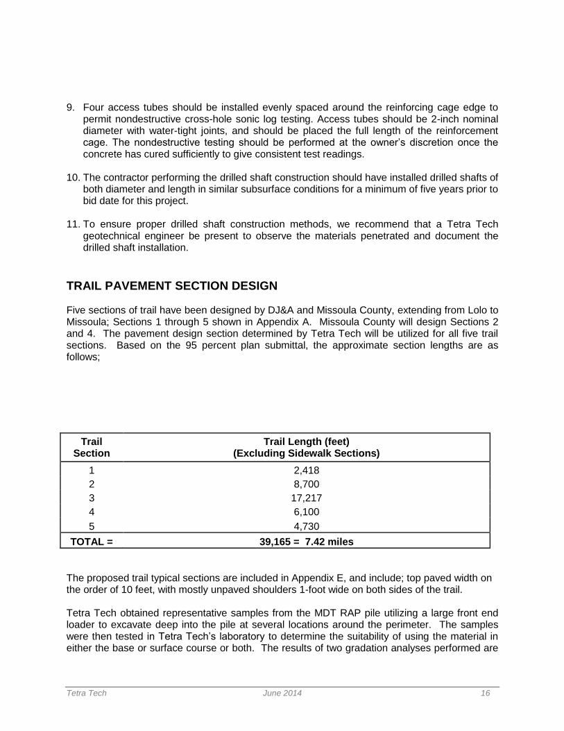
Five sections of trail have been designed by DJ&A and Missoula County, extending from Lolo to Missoula; Sections 1 through 5 shown in Appendix A. Missoula County will design Sections 2 and 4. The pavement design section determined by Tetra Tech will be utilized for all five trail sections. Based on the 95 percent plan submittal, the approximate section lengths are as follows;
Trail Section
Trail Length (feet) (Excluding Sidewalk Sections)
1 2,418
2 8,700
3 17,217
4 6,100
5 4,730
TOTAL = 39,165 = 7.42 miles
The proposed trail typical sections are included in Appendix E, and include; top paved width on the order of 10 feet, with mostly unpaved shoulders 1-foot wide on both sides of the trail. Tetra Tech obtained representative samples from the MDT RAP pile utilizing a large front end loader to excavate deep into the pile at several locations around the perimeter. The samples were then tested in Tetra Tech’s laboratory to determine the suitability of using the material in either the base or surface course or both. The results of two gradation analyses performed are
Tetra Tech June 2014 17
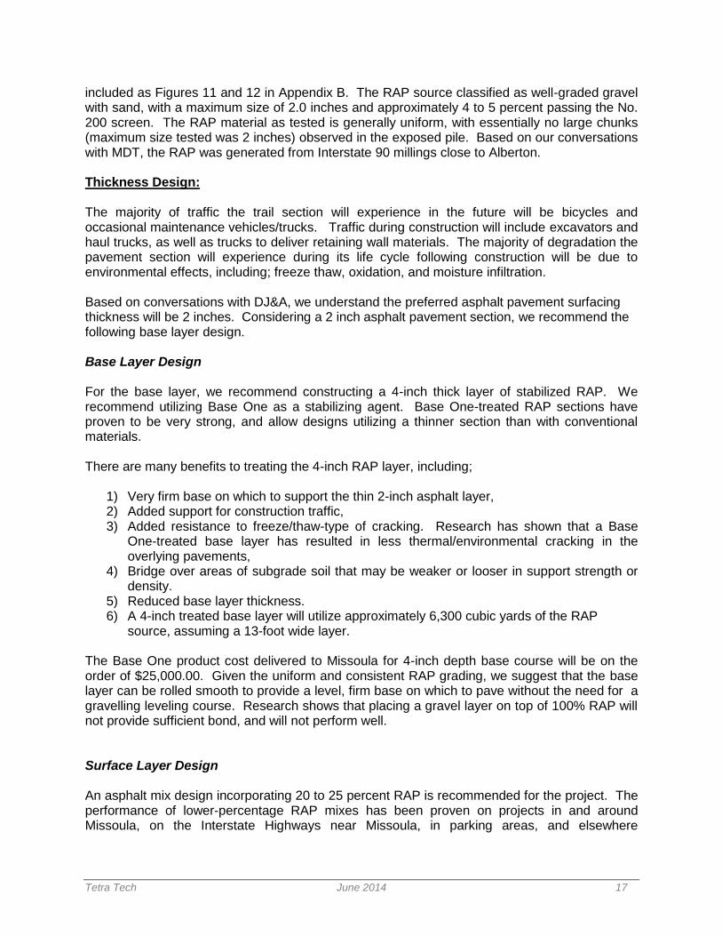
included as Figures 11 and 12 in Appendix B. The RAP source classified as well-graded gravel with sand, with a maximum size of 2.0 inches and approximately 4 to 5 percent passing the No. 200 screen. The RAP material as tested is generally uniform, with essentially no large chunks (maximum size tested was 2 inches) observed in the exposed pile. Based on our conversations with MDT, the RAP was generated from Interstate 90 millings close to Alberton. Thickness Design: The majority of traffic the trail section will experience in the future will be bicycles and occasional maintenance vehicles/trucks. Traffic during construction will include excavators and haul trucks, as well as trucks to deliver retaining wall materials. The majority of degradation the pavement section will experience during its life cycle following construction will be due to environmental effects, including; freeze thaw, oxidation, and moisture infiltration. Based on conversations with DJ&A, we understand the preferred asphalt pavement surfacing thickness will be 2 inches. Considering a 2 inch asphalt pavement section, we recommend the following base layer design. Base Layer Design For the base layer, we recommend constructing a 4-inch thick layer of stabilized RAP. We recommend utilizing Base One as a stabilizing agent. Base One-treated RAP sections have proven to be very strong, and allow designs utilizing a thinner section than with conventional materials. There are many benefits to treating the 4-inch RAP layer, including;
1) Very firm base on which to support the thin 2-inch asphalt layer, 2) Added support for construction traffic, 3) Added resistance to freeze/thaw-type of cracking. Research has shown that a Base
One-treated base layer has resulted in less thermal/environmental cracking in the overlying pavements,
4) Bridge over areas of subgrade soil that may be weaker or looser in support strength or density.
5) Reduced base layer thickness. 6) A 4-inch treated base layer will utilize approximately 6,300 cubic yards of the RAP
source, assuming a 13-foot wide layer.
The Base One product cost delivered to Missoula for 4-inch depth base course will be on the order of $25,000.00. Given the uniform and consistent RAP grading, we suggest that the base layer can be rolled smooth to provide a level, firm base on which to pave without the need for a gravelling leveling course. Research shows that placing a gravel layer on top of 100% RAP will not provide sufficient bond, and will not perform well. Surface Layer Design An asphalt mix design incorporating 20 to 25 percent RAP is recommended for the project. The performance of lower-percentage RAP mixes has been proven on projects in and around Missoula, on the Interstate Highways near Missoula, in parking areas, and elsewhere
Tetra Tech June 2014 18
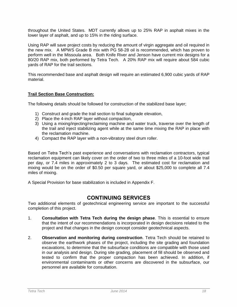
throughout the United States. MDT currently allows up to 25% RAP in asphalt mixes in the lower layer of asphalt, and up to 15% in the riding surface. Using RAP will save project costs by reducing the amount of virgin aggregate and oil required in the new mix. A MPWS Grade B mix with PG 58-28 oil is recommended, which has proven to perform well in the Missoula area. Both Knife River and Jenson have current mix designs for a 80/20 RAP mix, both performed by Tetra Tech. A 20% RAP mix will require about 584 cubic yards of RAP for the trail sections. This recommended base and asphalt design will require an estiimated 6,900 cubic yards of RAP material. Trail Section Base Construction: The following details should be followed for construction of the stabilized base layer;
1) Construct and grade the trail section to final subgrade elevation, 2) Place the 4-inch RAP layer without compaction, 3) Using a mixing/injecting/reclaiming machine and water truck, traverse over the length of
the trail and inject stabilizing agent while at the same time mixing the RAP in place with the reclamation machine.
4) Compact the RAP layer with a non-vibratory steel drum roller.
Based on Tetra Tech’s past experience and conversations with reclamation contractors, typical reclamation equipment can likely cover on the order of two to three miles of a 10-foot wide trail per day, or 7.4 miles in approximately 2 to 3 days. The estimated cost for reclamation and mixing would be on the order of $0.50 per square yard, or about $25,000 to complete all 7.4 miles of mixing.
A Special Provision for base stabilization is included in Appendix F.
CONTINUING SERVICES Two additional elements of geotechnical engineering service are important to the successful completion of this project. 1. Consultation with Tetra Tech during the design phase. This is essential to ensure
that the intent of our recommendations is incorporated in design decisions related to the project and that changes in the design concept consider geotechnical aspects.
2. Observation and monitoring during construction. Tetra Tech should be retained to
observe the earthwork phases of the project, including the site grading and foundation excavations, to determine that the subsurface conditions are compatible with those used in our analysis and design. During site grading, placement of fill should be observed and tested to confirm that the proper compaction has been achieved. In addition, if environmental contaminants or other concerns are discovered in the subsurface, our personnel are available for consultation.

Tetra Tech June 2014 19
LIMITATIONS This study has been conducted in accordance with generally accepted geotechnical engineering practices. The conclusions and recommendations submitted in this report are based upon the design data submitted to Tetra Tech, data obtained from the exploratory boring drilled at the location indicated, and the proposed construction discussed in this report. The nature and extent of subsurface variations across the site may not become evident until construction. During construction, if fill, soil, or water conditions appear to be different from those described herein, this office should be advised immediately so that we can re-evaluate our recommendations. This report has been prepared exclusively for our client for design purposes. We are not responsible for technical interpretations by others of our exploratory information that has not been described or documented in this report. As the project evolves, we should provide continued consultation and field services during construction to review and monitor the implementation of our recommendations, and verify that our recommendations have been appropriately interpreted. Significant design changes may require additional analysis or modifications of the recommendations presented herein. We recommend on-site observation of excavations and foundation bearing strata and testing of fill by a representative of the geotechnical engineer. Prepared by: Marco Fellin, P.E. Reviewed by: Richard Dombrouski, P.E
IMPORTANT INFORMATION ABOUT YOUR
GEOTECHNICAL ENGINEERING REPORT
More construction problems are caused by site subsurface conditions than any other factor. As troublesome as subsurface problems can be, their frequency and extent have been lessened considerably in recent years, due in large measure to programs and publications of ASFE/The Association of Engineering Firms Practicing in the Geosciences. The following suggestions and observations are offered to help you reduce the Geotechnical-related delays, cost-overruns and other costly headaches that can occur during a construction project.
A GEOTECHNICAL ENGINEERING REPORT IS BASED ON A UNIQUE SET OF
PROJECT-SPECIFIC FACTORS A Geotechnical engineering report is based on a subsurface exploration plan designed to incorporate a unique set of project-specific factors. These typically include: the general nature of the structure involved, its size and configuration; the location of the structure on the site and its orientation; physical concomitants such as access roads, parking lots, and underground utilities, and the level of additional risk which the client assumed by virtue of limitations imposed upon the exploratory program. To help avoid costly problems, consult the geotechnical engineer to determine how any factors which change subsequent to the date of the report may affect its recommendations. Unless your consulting Geotechnical engineer indicates otherwise, your Geotechnical engineer report should not be used:
When the nature of the proposed structure is changed, for example, if an office building will be erected instead of a parking garage, or if a refrigerated warehouse will be built instead of an unrefrigerated one;
when the size or configuration of the proposed structure is altered;
when the location or orientation of the proposed structure is modified:
when there is a change of ownership, or for application to an adjacent site.
Geotechnical engineers cannot accept responsibility for problems which may develop if they are not consulted after factors considered in their reports’ development have changed.
MOST GEOTECHNICAL “FINDINGS” ARE PROFESSIONAL ESTIMATES
Site exploration identifies actual subsurface conditions only at those points where samples are taken, when they are taken.
Data derived through sampling and subsequent laboratory testing are extrapolated by Geotechnical engineers who then render an opinion about overall subsurface conditions, their likely reaction to proposed conditions, their likely reaction to proposed construction activity, and appropriate foundation design. Even under optimal circumstances actual conditions may differ from those inferred to exist, because no Geotechnical engineer, no matter how qualified, and not subsurface exploration program, no matter how comprehensive, can reveal what is hidden by earth, rock and time. The actual interface between materials may be fare more gradual or abrupt than a report indicates. Actual conditions in areas not sampled may differ from predictions. Nothing can be done to prevent the unanticipated, but steps can be taken to help minimize their impact. For this reason, most experienced owners retain their Geotechnical consultants through the construction stage, to identify variances, conduct additional tests which may be needed, and to recommend solutions to problems encountered on site.
SUBSURFACE CONDITIONS CAN CHANGE
Subsurface conditions may be modified by constantly-changing natural forces. Because a Geotechnical engineering report is based on conditions which existed at the time of subsurface exploration, construction decisions should not be based on a Geotechnical engineering report whose adequacy may have been affected by time. Speak with the Geotechnical consultant to learn if additional tests are advisable before construction starts. Construction operations at or adjacent to the site and natural events such as flood, earthquakes or groundwater fluctuations may also affect subsurface conditions and, thus, the continuing adequacy of a geotechnical report. The geotechnical engineer should be kept apprised of any such events, and should be consulted to determine if additional tests are necessary.
GEOTECHNICAL SERVICES ARE PREFORMED FOR SPECIFIC PURPOSES
AND PERSONS Geotechnical engineers’ reports are prepared to meet the specific needs of specific individuals. A report prepared for a consulting civil engineer may not be adequate for a construction contractor, or even some other consulting civil engineer. Unless indicated otherwise, this report was prepared expressly for the client involved and expressly for purposes indicated by the client. Use by any other persons for any purpose, or by the client for a different purpose, may result in problems. No individual other than the client should apply this report for its intended purpose without first conferring with the
geotechnical engineer. No person should apply this report for any purpose other than that originally contemplated without first conferring with the geotechnical engineer.
A GEOTECHNICAL ENGINEERING REPORT IS SUBJECT TO MISINTERPRETATION
Costly problems can occur when other design professionals develop their plants based on misinterpretations of a geotechnical engineering report. To help avoid these problems, the geotechnical engineer should be retained to work with other appropriate design professionals to explain relevant geotechnical findings and to review the adequacy of their plans and specifications relative to geotechnical issues.
BORING LOGS SHOULD NOT BE SEPARATED FROM THE ENGINEERING REPORT
Final boring logs are developed by geotechnical engineers based upon their interpretation of field logs (assembled by site personnel) and laboratory evalution of field samples. Only final boring logs customarily are included in geotechnical engineering reports. These logs should not under any circumstances be redrawn for inclusion in architectural or other design drawings, because drafters may commit errors or omissions in the transfer process. Although photographic reproduction eliminates this problem, it does nothing to minimize the possibility of contractors misinterpreting the logs during bid preparation. When this occurs, delays, disputes and unanticipated costs are the all-too-frequent result. To minimize the likelihood of boring log misinterpretation, give contractors ready access to the complete geotechnical engineering report prepared or authorized for their use. Those
who do not provide such access may proceed under the mistaken impression that simply disclaiming responsibility for the accuracy of subsurface information always insulates them from attendant liability. Providing the best available information to contractors helps prevent costly construction problems and the adversarial attitudes which aggravate them to disproportionate scale.
READ RESPONSIBILITY CLAUSES CLOSELY
Because geotechnical engineering is based extensively on judgment and opinion, it is far less exact than other design disciplines. This situation has resulted in wholly unwarranted claims being lodged against geotechnical consultants. To help prevent this problem, geotechnical engineers have developed model clauses for use in written transmittals. These are not exculpatory clauses designed to foist geotechnical engineers’ liabilities onto someone else. Rather, they are definitive clauses which identify where geotechnical engineers’ responsibilities begin and end. Their use helps all parties involved recognize their individual responsibilities and take appropriate action. Some of these definitive clauses are likely to appear in your geotechnical engineering report, and you are encouraged to read them closely. your geotechnical engineer will be pleased to give full and frank answers to your questions.
OTHER STEPS YOU CAN TAKE TO REDUCE RISK
Your consulting geotechnical engineer will be pleased to discuss other techniques which can be employed to mitigate risk. In addition, ASFE as developed a variety of materials which may be beneficial. Contact ASFE for a complimentary copy of its publications directory.
Published by
THE ASSOCIATION OF ENGINEERING FIRMS PRACTICING IN THE GEOESCIENCES
8811 Colesville Road/Suite G106/Silver Spring, Maryland 20910/(301)565-2733
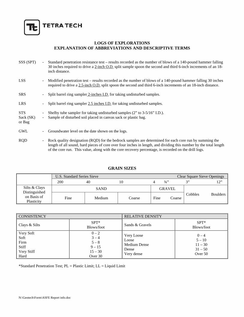
LOGS OF EXPLORATIONS
EXPLANATION OF ABBREVIATIONS AND DESCRIPTIVE TERMS SSS (SPT) - Standard penetration resistance test – results recorded as the number of blows of a 140-pound hammer falling
30 inches required to drive a 2-inch O.D. split sample spoon the second and third 6-inch increments of an 18-inch distance.
LSS - Modified penetration test – results recorded as the number of blows of a 140-pound hammer falling 30 inches required to drive a 2.5-inch O.D. split spoon the second and third 6-inch increments of an 18-inch distance.
SRS - Split barrel ring sampler 2-inches I.D. for taking undisturbed samples.
LRS - Split barrel ring sampler 2.5 inches I.D. for taking undisturbed samples.
STS - Shelby tube sampler for taking undisturbed samples (2” to 3-5/16” I.D.). Sack (SK) or Bag
- Sample of disturbed soil placed in canvas sack or plastic bag.
GWL - Groundwater level on the date shown on the logs.
RQD - Rock quality designation (RQD) for the bedrock samples are determined for each core run by summing the length of all sound, hard pieces of core over four inches in length, and dividing this number by the total length of the core run. This value, along with the core recovery percentage, is recorded on the drill logs.
GRAIN SIZES
U.S. Standard Series Sieve Clear Square Sieve Openings
200 40 10 4 ¾” 3” 12”
SAND GRAVEL Silts & Clays Distinguished
on Basis of Plasticity
Fine Medium Coarse Fine Coarse Cobbles Boulders
CONSISTENCY RELATIVE DENSITY
Clays & Silts SPT* Blows/foot Sands & Gravels SPT*
Blows/foot Very Soft Soft Firm Stiff Very Stiff Hard
0 – 2 3 – 4 5 – 8
9 – 15 15 – 30 Over 30
Very Loose Loose Medium Dense Dense Very dense
0 – 4 5 – 10 11 – 30 31 – 50 Over 50
*Standard Penetration Test; PL = Plastic Limit; LL = Liquid Limit N:\Geotech\Form\ASFE Report info.doc
D50 15 (D30)2 (2.5)- D1e 0.075 D12 x 1036 0.075 x 15
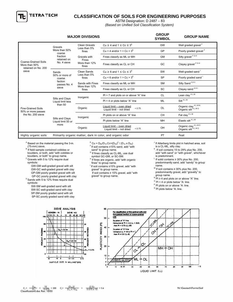
CLASSIFICATION OF SOILS FOR ENGINEERING PURPOSES ASTM Designation: D 2487 – 83
(Based on Unified Soil Classification System)
Cu = = = 200 Cc= + = 5.6 N::\Geotech\Forms\Soil Classifications.doc Rev. 10/03
< 0.75
< 0.75
MAJOR DIVISIONS GROUP SYMBOL GROUP NAME
Cu ≥ 4 and 1 ≤ Cc ≤ 3E GW Well graded gravel F Clean Gravels Less than 5%
fines Cu < 4 and/or 1 > Cc > 3E GP Poorly graded gravel F
Fines classify as ML or MH GM Silty gravel F G H
Gravels More than 50%
coarse fraction retained on No. 4 sieve
Gravels with Fines
More than 12% fines
Fines classify as CL or CH GC Clayey gravel F G H
Cu ≥ 6 and 1 ≤ Cc ≤ 3E SW Well-graded sand I Clean Sands Less than 5%
fines Cu < 6 and/or 1 > Cc > 3E SP Poorly graded sand I
Fines classify as ML or MH SM Silty Sand G H I
Coarse-Grained Soils More than 50%
retained on No. 200 sieve Sands
50% or more of coarse faction passes No. 4 sieve
Sands with Fines More than 12%
fines Fines classify as CL or CH SC Clayey sand G H I
Pl > 7 and plots on or above “A” line CL Lean clay K L M Inorganic
Pl < 4 or plots below “A” line ML Silt K L M Silts and Clays Liquid limit less
than 50 Organic Liquid limit – oven dried
Liquid limit – not dried OL Organic clay K L M N
Organic silt K L M O
Pl plots on or above “A” line CH Fat clay K L M Inorganic
Pl plots below “A” line MH Elastic silt K L M
Fine-Grained Soils 50% or more passes
the No. 200 sieve Silts and Clays Liquid limit 50 or
more Organic Liquid limit – oven dried
Liquid limit – not dried OH Organic clay K L M O
Organic silt K L M O
Highly organic soils Primarily organic matter, dark in color, and organic odor PT Peat
A Based on the material passing the 3-in. (75-mm) sieve.
B If field sample contained cobbles or boulders, or both, add “with cobbles or boulders, or both” to group name.
C Gravels with 5 to 12% require dual symbols: GW-GM well-graded gravel with silt GW-GC well-graded gravel with clay GP-GM poorly graded gravel with silt
GP-GC poorly graded gravel with clay D Sands with 5 to 12% fines require dual
symbols: SW-SM well-graded sand with silt SW-SC well-graded sand with clay SP-SM poorly graded sand with silt
SP-SC poorly graded sand with clay
E Cu = D60/D10 Cc=(D30)2 / (D10 x D90) F If soil contains ≥15% sand, add “with
sand” to group name. G If fines classify as CL-ML, use dual
symbol GC-GM, or SC-SM. H If fines are organic, add “with organic
fines” to group name. I If soil contains ≥15% gravel, add “with
gravel” to group name. If soil contains ≥ 15% gravel, add “with
gravel” to group name.
J If Atterberg limits plot in hatched area, soil is a CL-ML, silty clay.
K. If soil contains 15 to 29% plus No. 200, add “with sand” or “with gravel”, whichever is predominant.
L If solid contains ≥ 30% plus No. 200, predominantly sand, add “sandy” to group name.
M If soil contains ≥ 30% plus No. 200, predominantly gravel, add “gravelly” to group name.
N Pl ≥ 4 and plots on or above “A” line. O Pl < 4 or plots below “A: line. P Pl plots on or above “A: line. Q Pl plots below “A: line.

APPENDIX A
�������������
�����
�����
������
�����
���
���
�
��
�����
�����
�����
���
�����
������
�����
�������
����
��LOLO
��
��
MISSOULA
RE
SE
RV
E S
TR
EE
T
MONTANA
RAIL LINK
BRO
OKS S
TREET
MIL
LE
R C
RE
EK
SOUTH AVE.
THIRD STREET
OLD
HWY 9
3
BLUE MT
N. RD.
������
������
������
�������������
������������������ ���� ����������� ������ ��
F:\
60
78
.02
Mis
so
ula
to
Lo
lo T
rail D
esig
n\d
wg
\60
78
_S
he
ets
_A
_V
icin
ity.d
wg
.dw
g, B
OR
E H
OLE
, 6/6
/2014 3
:49:4
7 P
M, D
anL

APPENDIX B
30
40
50
95
70
70
70
0.50
9.00
13.00
28.50
25 10
9-14-14
5-12-14
18-17-17
10-19-15
12-9-18
23-19-16
8-14-12
7
4
5
7
5
5
2
FILL, Lean CLAY (CL), tan, moist, lowplasticity.FILL, Clayey GRAVEL with sand (GC), fineto coarse grained gravel, fine to mediumgrained sand, medium dense to dense,gray, moist, angular gravel, low plasticity.
FILL, lean CLAY with sand (CL), fine tomedium grained sand, gray, moist, lowplasticity.
Poorly graded GRAVEL with silt and sand(GP-GM) to (SP-SM), fine to mediumgrained gravel, fine to coarse grained sand,medium dense to dense, tan/brown, moist,angular gravel, non-plastic.
Bottom of Boring at 28.5 ft
16
SplitSpoon
Upon Completion of Drilling
Depth To Water (ft)
Driller:
Date Started:
DE
PT
H (
ft)
Vane Shear
LOG OF BORING
DRILL
California Ring
OP
ER
AT
ION
Logger:
BH-1
6.00
WATER LEVEL OBSERVATIONS
1
5
10
15
20
25
RO
CK
QU
ALI
TY
DE
SIG
NA
TIO
N (
RQ
D)
Drilling Equipment:
BulkSample
Testpit
SamplerTypes:
3138.60
of
MIN
US
NO
. 200
(%
)
SPTP
LAS
TIC
ITY
IND
EX
PI
Hammer:Type:
BoreholeNumber:
DriveCasing
Ground:
Project Name:
Borehole Location:
Stationing:
MudRotary
1
SA
MP
LE
RE
CO
VE
RY
(%
)
Penetrometer
PR
ES
SU
RE
(ps
i)
RA
TE
(m
ph)
Figure No. 1
LLLI
QU
ID L
IMIT
Elevationand Datum:
Shelby
Refer to Site Map
Date Finished:
Notes:
DE
PT
H (
ft)
ft
Auger
DiamondCore
ContinuousFlight Auger
WashRotary
Remarks:
Northing: 959837.77Easting: 816937.02
MO
IST
UR
E C
ON
TE
NT
(%
)
GrabSample
OperationTypes:
CO
RE
PE
RC
EN
T R
EC
OV
ER
Y
Time After Drilling
MATERIAL DESCRIPTION
ft
1-09-14 1-09-14
REMARKS
Tetra Tech
Phone: 406-543-3045Fax: 406-543-3088
Sheet
5707
18 L
OG
S.G
PJ
` 6
-12
-14
` M
AT
` M
ON
TA
NA
DO
T E
NG
LIS
H O
UT
PU
T
114-570718
ST
AN
DA
RD
PE
NE
TR
AT
ION
TE
ST
O'Keefe - Butte
GR
AP
HIC
LO
G
DR
Y D
EN
SIT
Y (
pcf)
Air Rotary DryWhile Drilling
BoreholeDiameter (in):
Project Number:
Kyle Zanto
Revised 5-17-11 (MAT)
Mobile B-61
Lolo Bike Trail - Missoula County, Montana
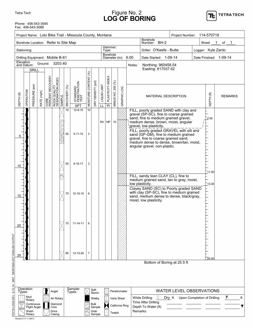
10
50
55
70
70
80
2.00
11.00
13.00
25.50
NV NP
12-9-15
5-11-15
9-15-17
12-15-15
11-14-11
13-13-20
10
3
3
6
6
7
FILL, poorly graded SAND with clay andgravel (SP-SC), fine to coarse grainedsand, fine to medium grained gravel,medium dense, brown, moist, angulargravel, low plasticity.FILL, poorly graded GRAVEL with silt andsand (GP-GM), fine to medium grainedgravel, fine to coarse grained sand,medium dense to dense, brown/tan, moist,angular gravel, non-plastic.
FILL, sandy lean CLAY (CL), fine tomedium grained sand, tan to gray, moist,low plasticity.Clayey SAND (SC) to Poorly graded SANDwith clay (SP-SC), fine to medium grainedsand, medium dense to dense, black/gray,moist, low plasticity.
Bottom of Boring at 25.5 ft
10
SplitSpoon
Upon Completion of Drilling
Depth To Water (ft)
Driller:
Date Started:
DE
PT
H (
ft)
Vane Shear
LOG OF BORING
DRILL
California Ring
OP
ER
AT
ION
Logger:
BH-2
6.00
WATER LEVEL OBSERVATIONS
1
5
10
15
20
25
RO
CK
QU
ALI
TY
DE
SIG
NA
TIO
N (
RQ
D)
Drilling Equipment:
BulkSample
Testpit
SamplerTypes:
3203.40
of
MIN
US
NO
. 200
(%
)
SPTP
LAS
TIC
ITY
IND
EX
PI
Hammer:Type:
BoreholeNumber:
DriveCasing
Ground:
Project Name:
Borehole Location:
Stationing:
MudRotary
1
SA
MP
LE
RE
CO
VE
RY
(%
)
Penetrometer
PR
ES
SU
RE
(ps
i)
RA
TE
(m
ph)
Figure No. 2
LLLI
QU
ID L
IMIT
Elevationand Datum:
Shelby
Refer to Site Map
Date Finished:
Notes:
DE
PT
H (
ft)
ft
Auger
DiamondCore
ContinuousFlight Auger
WashRotary
Remarks:
Northing: 960458.54Easting: 817037.62
MO
IST
UR
E C
ON
TE
NT
(%
)
GrabSample
OperationTypes:
CO
RE
PE
RC
EN
T R
EC
OV
ER
Y
Time After Drilling
MATERIAL DESCRIPTION
ft
1-09-14 1-09-14
REMARKS
Tetra Tech
Phone: 406-543-3045Fax: 406-543-3088
Sheet
5707
18 L
OG
S.G
PJ
` 6
-12
-14
` M
AT
` M
ON
TA
NA
DO
T E
NG
LIS
H O
UT
PU
T
114-570718
ST
AN
DA
RD
PE
NE
TR
AT
ION
TE
ST
O'Keefe - Butte
GR
AP
HIC
LO
G
DR
Y D
EN
SIT
Y (
pcf)
Air Rotary DryWhile Drilling
BoreholeDiameter (in):
Project Number:
Kyle Zanto
Revised 5-17-11 (MAT)
Mobile B-61
Lolo Bike Trail - Missoula County, Montana
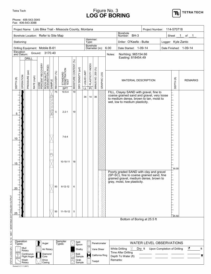
75
5
50
50
16.00
25.50
34 14
10-5-4
2-2-1
7-6-4
10-10-11
6-12-12
11-15-12
19
19
18
6
5
FILL, Clayey SAND with gravel, fine tocoarse grained sand and gravel, very looseto medium dense, brown to tan, moist towet, low to medium plasticity.
Poorly graded SAND with clay and gravel(SP-SC), fine to coarse grained sand, finegrained gravel, medium dense, brown togray, moist, low plasticity.
Bottom of Boring at 25.5 ft
36
SplitSpoon
Upon Completion of Drilling
Depth To Water (ft)
Driller:
Date Started:
DE
PT
H (
ft)
Vane Shear
LOG OF BORING
DRILL
California Ring
OP
ER
AT
ION
Logger:
BH-3
6.00
WATER LEVEL OBSERVATIONS
1
5
10
15
20
25
RO
CK
QU
ALI
TY
DE
SIG
NA
TIO
N (
RQ
D)
Drilling Equipment:
BulkSample
Testpit
SamplerTypes:
3170.40
of
MIN
US
NO
. 200
(%
)
SPTP
LAS
TIC
ITY
IND
EX
PI
Hammer:Type:
BoreholeNumber:
DriveCasing
Ground:
Project Name:
Borehole Location:
Stationing:
MudRotary
1
SA
MP
LE
RE
CO
VE
RY
(%
)
Penetrometer
PR
ES
SU
RE
(ps
i)
RA
TE
(m
ph)
Figure No. 3
LLLI
QU
ID L
IMIT
Elevationand Datum:
Shelby
Refer to Site Map
Date Finished:
Notes:
DE
PT
H (
ft)
ft
Auger
DiamondCore
ContinuousFlight Auger
WashRotary
Remarks:
Norhting: 965154.66Easting: 818454.49
MO
IST
UR
E C
ON
TE
NT
(%
)
GrabSample
OperationTypes:
CO
RE
PE
RC
EN
T R
EC
OV
ER
Y
Time After Drilling
MATERIAL DESCRIPTION
ft
1-09-14 1-09-14
REMARKS
Tetra Tech
Phone: 406-543-3045Fax: 406-543-3088
Sheet
5707
18 L
OG
S.G
PJ
` 6
-12
-14
` M
AT
` M
ON
TA
NA
DO
T E
NG
LIS
H O
UT
PU
T
114-570718
ST
AN
DA
RD
PE
NE
TR
AT
ION
TE
ST
O'Keefe - Butte
GR
AP
HIC
LO
G
DR
Y D
EN
SIT
Y (
pcf)
Air Rotary DryWhile Drilling
BoreholeDiameter (in):
Project Number:
Kyle Zanto
Revised 5-17-11 (MAT)
Mobile B-61
Lolo Bike Trail - Missoula County, Montana
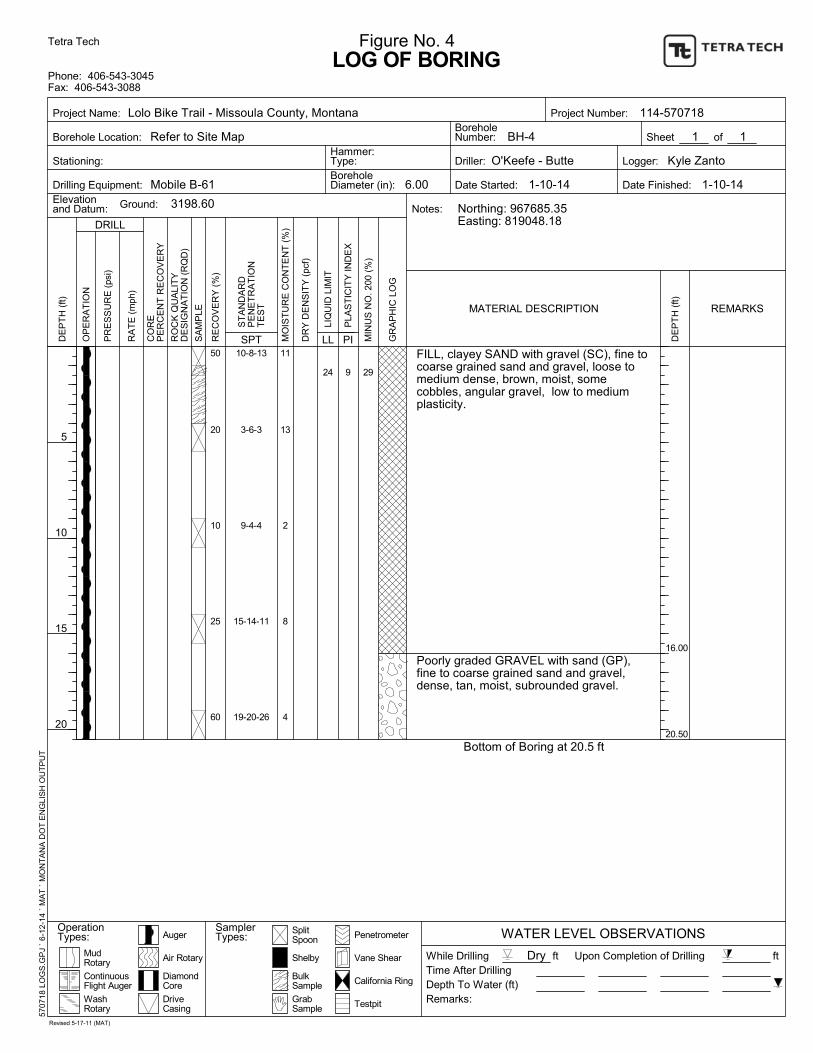
50
20
10
25
60
16.00
20.50
24 9
10-8-13
3-6-3
9-4-4
15-14-11
19-20-26
11
13
2
8
4
FILL, clayey SAND with gravel (SC), fine tocoarse grained sand and gravel, loose tomedium dense, brown, moist, somecobbles, angular gravel, low to mediumplasticity.
Poorly graded GRAVEL with sand (GP),fine to coarse grained sand and gravel,dense, tan, moist, subrounded gravel.
Bottom of Boring at 20.5 ft
29
SplitSpoon
Upon Completion of Drilling
Depth To Water (ft)
Driller:
Date Started:
DE
PT
H (
ft)
Vane Shear
LOG OF BORING
DRILL
California Ring
OP
ER
AT
ION
Logger:
BH-4
6.00
WATER LEVEL OBSERVATIONS
1
5
10
15
20
RO
CK
QU
ALI
TY
DE
SIG
NA
TIO
N (
RQ
D)
Drilling Equipment:
BulkSample
Testpit
SamplerTypes:
3198.60
of
MIN
US
NO
. 200
(%
)
SPTP
LAS
TIC
ITY
IND
EX
PI
Hammer:Type:
BoreholeNumber:
DriveCasing
Ground:
Project Name:
Borehole Location:
Stationing:
MudRotary
1
SA
MP
LE
RE
CO
VE
RY
(%
)
Penetrometer
PR
ES
SU
RE
(ps
i)
RA
TE
(m
ph)
Figure No. 4
LLLI
QU
ID L
IMIT
Elevationand Datum:
Shelby
Refer to Site Map
Date Finished:
Notes:
DE
PT
H (
ft)
ft
Auger
DiamondCore
ContinuousFlight Auger
WashRotary
Remarks:
Northing: 967685.35Easting: 819048.18
MO
IST
UR
E C
ON
TE
NT
(%
)
GrabSample
OperationTypes:
CO
RE
PE
RC
EN
T R
EC
OV
ER
Y
Time After Drilling
MATERIAL DESCRIPTION
ft
1-10-14 1-10-14
REMARKS
Tetra Tech
Phone: 406-543-3045Fax: 406-543-3088
Sheet
5707
18 L
OG
S.G
PJ
` 6
-12
-14
` M
AT
` M
ON
TA
NA
DO
T E
NG
LIS
H O
UT
PU
T
114-570718
ST
AN
DA
RD
PE
NE
TR
AT
ION
TE
ST
O'Keefe - Butte
GR
AP
HIC
LO
G
DR
Y D
EN
SIT
Y (
pcf)
Air Rotary DryWhile Drilling
BoreholeDiameter (in):
Project Number:
Kyle Zanto
Revised 5-17-11 (MAT)
Mobile B-61
Lolo Bike Trail - Missoula County, Montana
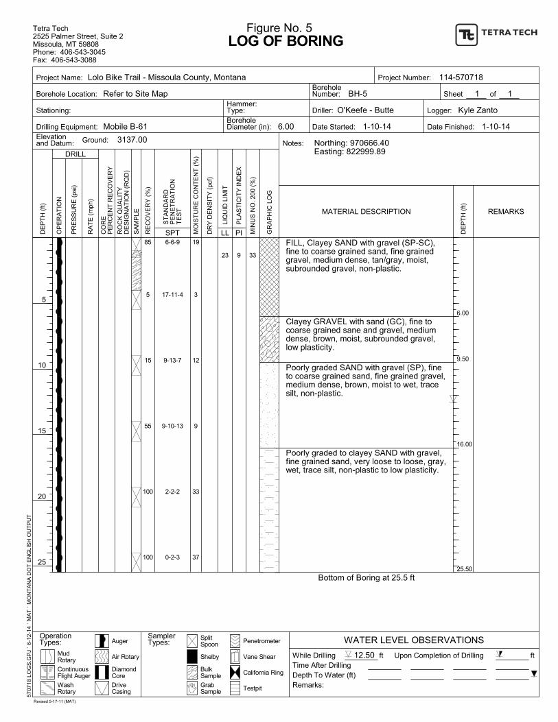
85
5
15
55
100
100
6.00
9.50
16.00
25.50
23 9
6-6-9
17-11-4
9-13-7
9-10-13
2-2-2
0-2-3
19
3
12
9
33
37
FILL, Clayey SAND with gravel (SP-SC),fine to coarse grained sand, fine grainedgravel, medium dense, tan/gray, moist,subrounded gravel, non-plastic.
Clayey GRAVEL with sand (GC), fine tocoarse grained sane and gravel, mediumdense, brown, moist, subrounded gravel,low plasticity.
Poorly graded SAND with gravel (SP), fineto coarse grained sand, fine grained gravel,medium dense, brown, moist to wet, tracesilt, non-plastic.
Poorly graded to clayey SAND with gravel,fine grained sand, very loose to loose, gray,wet, trace silt, non-plastic to low plasticity.
Bottom of Boring at 25.5 ft
33
SplitSpoon
Upon Completion of Drilling
Depth To Water (ft)
Driller:
Date Started:
DE
PT
H (
ft)
Vane Shear
LOG OF BORING
DRILL
California Ring
OP
ER
AT
ION
Logger:
BH-5
6.00
WATER LEVEL OBSERVATIONS
1
5
10
15
20
25
RO
CK
QU
ALI
TY
DE
SIG
NA
TIO
N (
RQ
D)
Drilling Equipment:
BulkSample
Testpit
SamplerTypes:
3137.00
of
MIN
US
NO
. 200
(%
)
SPTP
LAS
TIC
ITY
IND
EX
PI
Hammer:Type:
BoreholeNumber:
DriveCasing
Ground:
Project Name:
Borehole Location:
Stationing:
MudRotary
1
SA
MP
LE
RE
CO
VE
RY
(%
)
Penetrometer
PR
ES
SU
RE
(ps
i)
RA
TE
(m
ph)
Figure No. 5
LLLI
QU
ID L
IMIT
Elevationand Datum:
Shelby
Refer to Site Map
Date Finished:
Notes:
DE
PT
H (
ft)
ft
Auger
DiamondCore
ContinuousFlight Auger
WashRotary
Remarks:
Northing: 970666.40Easting: 822999.89
MO
IST
UR
E C
ON
TE
NT
(%
)
GrabSample
OperationTypes:
CO
RE
PE
RC
EN
T R
EC
OV
ER
Y
Time After Drilling
MATERIAL DESCRIPTION
ft
1-10-14 1-10-14
REMARKS
Tetra Tech2525 Palmer Street, Suite 2Missoula, MT 59808Phone: 406-543-3045Fax: 406-543-3088
Sheet
5707
18 L
OG
S.G
PJ
` 6
-12
-14
` M
AT
` M
ON
TA
NA
DO
T E
NG
LIS
H O
UT
PU
T
114-570718
ST
AN
DA
RD
PE
NE
TR
AT
ION
TE
ST
O'Keefe - Butte
GR
AP
HIC
LO
G
DR
Y D
EN
SIT
Y (
pcf)
Air Rotary 12.50While Drilling
BoreholeDiameter (in):
Project Number:
Kyle Zanto
Revised 5-17-11 (MAT)
Mobile B-61
Lolo Bike Trail - Missoula County, Montana

0.75
2.00
18.00
25.50
22 7
14-11-13
14-42-27
9-7-10-13
12-19-12
20-33-31
12-22-34
5
3
4
5
4
4
AsphaltGranular Base Course, Poorly GradedGravel and Sand.FILL. Silty Clayey Gravel with Sand,medium to very dense, subrounded tosubangular, slightly moist, brown,occasional cobbles.
Silty Clayey Gravel with Sand (GC-GM),very dense, subrounded, slightly moist,brown, occasional cobbles.
Bottom of Boring 25.5'
17
SplitSpoon
Upon Completion of Drilling
Depth To Water (ft)
Driller:
Date Started:
DE
PT
H (
ft)
Vane Shear
LOG OF BORING
DRILL
California Ring
OP
ER
AT
ION
Logger:
R-2
8.00
WATER LEVEL OBSERVATIONS
1
5
10
15
20
25
RO
CK
QU
ALI
TY
DE
SIG
NA
TIO
N (
RQ
D)
Drilling Equipment:
BulkSample
Testpit
SamplerTypes:
3176.43'
of
MIN
US
NO
. 200
(%
)
SPTP
LAS
TIC
ITY
IND
EX
PI
Hammer:Type:
BoreholeNumber:
DriveCasing
Ground:
Project Name:
Borehole Location:
Stationing:
MudRotary
1
SA
MP
LE
RE
CO
VE
RY
(%
)
Penetrometer
PR
ES
SU
RE
(ps
i)
RA
TE
(m
ph)
Figure No. 6
LLLI
QU
ID L
IMIT
Elevationand Datum:
Shelby
2011+00
Date Finished:
Notes:
DE
PT
H (
ft)
ft
Auger
DiamondCore
ContinuousFlight Auger
WashRotary
Remarks:
N 951539.69' E 822248.42'
MO
IST
UR
E C
ON
TE
NT
(%
)
GrabSample
OperationTypes:
CO
RE
PE
RC
EN
T R
EC
OV
ER
Y
Time After Drilling
MATERIAL DESCRIPTION
ft
05/05/2014 05/05/2014
Automatic
REMARKS
Tetra Tech2525 Palmer Street, Suite 2Missoula, MT 59808Phone: 406-543-3045Fax: 406-543-3088
Sheet
LOLO
LO
G_D
AT
A.G
PJ
` 6-
12-
14
` A
JK `
MO
NT
AN
A D
OT
EN
GLI
SH
OU
TP
UT
114-570781
ST
AN
DA
RD
PE
NE
TR
AT
ION
TE
ST
O'Keefe Drilling
GR
AP
HIC
LO
G
DR
Y D
EN
SIT
Y (
pcf)
Air Rotary NEWhile Drilling
BoreholeDiameter (in):
Project Number:
Daniel Earnest
Revised 5-17-11 (MAT)
Mobile B-61
MISSOULA TO LOLO TRAIL
2011+00
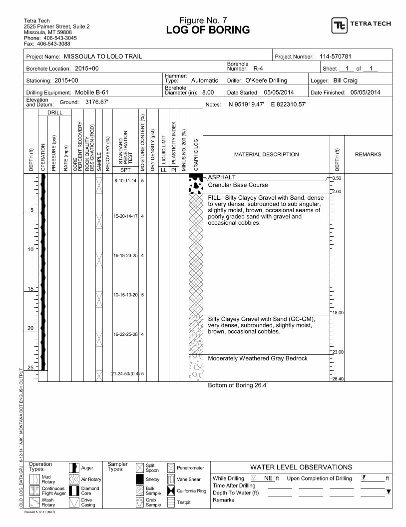
0.50
2.60
18.00
23.00
26.40
8-10-11-14
15-20-14-17
16-18-23-25
10-15-19-20
16-22-25-28
21-24-50/(0.4)
5
4
4
5
4
5
ASPHALTGranular Base Course
FILL. Silty Clayey Gravel with Sand, denseto very dense, subrounded to sub angular,slightly moist, brown, occasional seams ofpoorly graded sand with gravel andoccasional cobbles.
Silty Clayey Gravel with Sand (GC-GM),very dense, subrounded, slightly moist,brown, occasional cobbles.
Moderately Weathered Gray Bedrock
Bottom of Boring 26.4'
SplitSpoon
Upon Completion of Drilling
Depth To Water (ft)
Driller:
Date Started:
DE
PT
H (
ft)
Vane Shear
LOG OF BORING
DRILL
California Ring
OP
ER
AT
ION
Logger:
R-4
8.00
WATER LEVEL OBSERVATIONS
1
5
10
15
20
25
RO
CK
QU
ALI
TY
DE
SIG
NA
TIO
N (
RQ
D)
Drilling Equipment:
BulkSample
Testpit
SamplerTypes:
3176.67'
of
MIN
US
NO
. 200
(%
)
SPTP
LAS
TIC
ITY
IND
EX
PI
Hammer:Type:
BoreholeNumber:
DriveCasing
Ground:
Project Name:
Borehole Location:
Stationing:
MudRotary
1
SA
MP
LE
RE
CO
VE
RY
(%
)
Penetrometer
PR
ES
SU
RE
(ps
i)
RA
TE
(m
ph)
Figure No. 7
LLLI
QU
ID L
IMIT
Elevationand Datum:
Shelby
2015+00
Date Finished:
Notes:
DE
PT
H (
ft)
ft
Auger
DiamondCore
ContinuousFlight Auger
WashRotary
Remarks:
N 951919.47' E 822310.57'
MO
IST
UR
E C
ON
TE
NT
(%
)
GrabSample
OperationTypes:
CO
RE
PE
RC
EN
T R
EC
OV
ER
Y
Time After Drilling
MATERIAL DESCRIPTION
ft
05/05/2014 05/05/2014
Automatic
REMARKS
Tetra Tech2525 Palmer Street, Suite 2Missoula, MT 59808Phone: 406-543-3045Fax: 406-543-3088
Sheet
LOLO
LO
G_D
AT
A.G
PJ
` 6-
12-
14
` A
JK `
MO
NT
AN
A D
OT
EN
GLI
SH
OU
TP
UT
114-570781
ST
AN
DA
RD
PE
NE
TR
AT
ION
TE
ST
O'Keefe Drilling
GR
AP
HIC
LO
G
DR
Y D
EN
SIT
Y (
pcf)
Air Rotary NEWhile Drilling
BoreholeDiameter (in):
Project Number:
Bill Craig
Revised 5-17-11 (MAT)
Mobiile B-61
MISSOULA TO LOLO TRAIL
2015+00
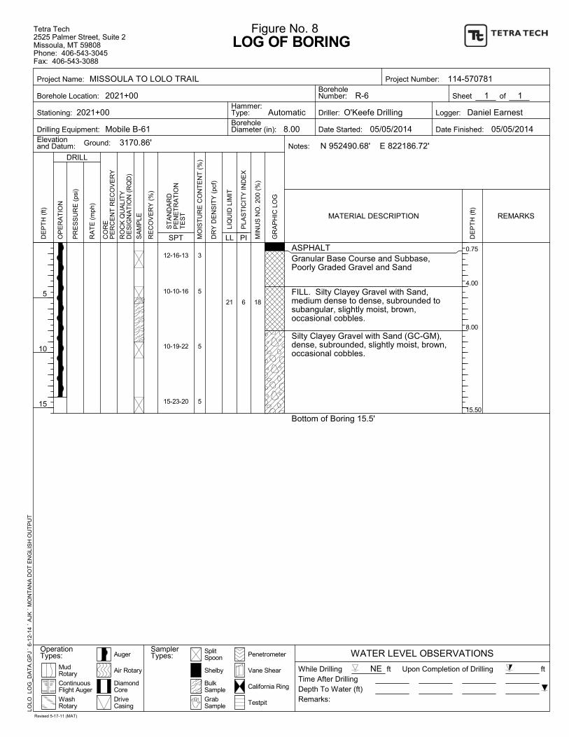
0.75
4.00
8.00
15.50
21 6
12-16-13
10-10-16
10-19-22
15-23-20
3
5
5
5
ASPHALTGranular Base Course and Subbase,Poorly Graded Gravel and Sand
FILL. Silty Clayey Gravel with Sand,medium dense to dense, subrounded tosubangular, slightly moist, brown,occasional cobbles.
Silty Clayey Gravel with Sand (GC-GM),dense, subrounded, slightly moist, brown,occasional cobbles.
Bottom of Boring 15.5'
18
SplitSpoon
Upon Completion of Drilling
Depth To Water (ft)
Driller:
Date Started:
DE
PT
H (
ft)
Vane Shear
LOG OF BORING
DRILL
California Ring
OP
ER
AT
ION
Logger:
R-6
8.00
WATER LEVEL OBSERVATIONS
1
5
10
15
RO
CK
QU
ALI
TY
DE
SIG
NA
TIO
N (
RQ
D)
Drilling Equipment:
BulkSample
Testpit
SamplerTypes:
3170.86'
of
MIN
US
NO
. 200
(%
)
SPTP
LAS
TIC
ITY
IND
EX
PI
Hammer:Type:
BoreholeNumber:
DriveCasing
Ground:
Project Name:
Borehole Location:
Stationing:
MudRotary
1
SA
MP
LE
RE
CO
VE
RY
(%
)
Penetrometer
PR
ES
SU
RE
(ps
i)
RA
TE
(m
ph)
Figure No. 8
LLLI
QU
ID L
IMIT
Elevationand Datum:
Shelby
2021+00
Date Finished:
Notes:
DE
PT
H (
ft)
ft
Auger
DiamondCore
ContinuousFlight Auger
WashRotary
Remarks:
N 952490.68' E 822186.72'
MO
IST
UR
E C
ON
TE
NT
(%
)
GrabSample
OperationTypes:
CO
RE
PE
RC
EN
T R
EC
OV
ER
Y
Time After Drilling
MATERIAL DESCRIPTION
ft
05/05/2014 05/05/2014
Automatic
REMARKS
Tetra Tech2525 Palmer Street, Suite 2Missoula, MT 59808Phone: 406-543-3045Fax: 406-543-3088
Sheet
LOLO
LO
G_D
AT
A.G
PJ
` 6-
12-
14
` A
JK `
MO
NT
AN
A D
OT
EN
GLI
SH
OU
TP
UT
114-570781
ST
AN
DA
RD
PE
NE
TR
AT
ION
TE
ST
O'Keefe Drilling
GR
AP
HIC
LO
G
DR
Y D
EN
SIT
Y (
pcf)
Air Rotary NEWhile Drilling
BoreholeDiameter (in):
Project Number:
Daniel Earnest
Revised 5-17-11 (MAT)
Mobile B-61
MISSOULA TO LOLO TRAIL
2021+00
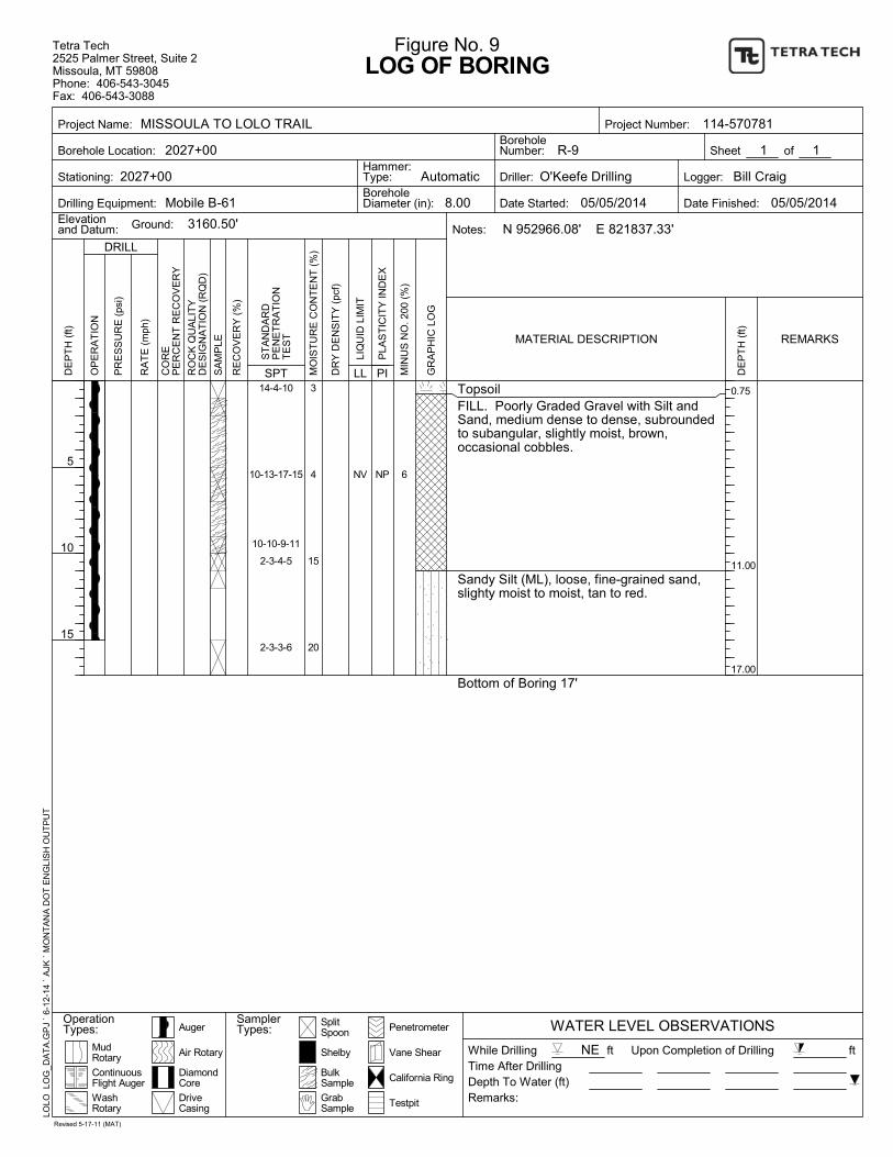
0.75
11.00
17.00
NV NP
14-4-10
10-13-17-15
10-10-9-11
2-3-4-5
2-3-3-6
3
4
15
20
TopsoilFILL. Poorly Graded Gravel with Silt andSand, medium dense to dense, subroundedto subangular, slightly moist, brown,occasional cobbles.
Sandy Silt (ML), loose, fine-grained sand,slighty moist to moist, tan to red.
Bottom of Boring 17'
6
SplitSpoon
Upon Completion of Drilling
Depth To Water (ft)
Driller:
Date Started:
DE
PT
H (
ft)
Vane Shear
LOG OF BORING
DRILL
California Ring
OP
ER
AT
ION
Logger:
R-9
8.00
WATER LEVEL OBSERVATIONS
1
5
10
15
RO
CK
QU
ALI
TY
DE
SIG
NA
TIO
N (
RQ
D)
Drilling Equipment:
BulkSample
Testpit
SamplerTypes:
3160.50'
of
MIN
US
NO
. 200
(%
)
SPTP
LAS
TIC
ITY
IND
EX
PI
Hammer:Type:
BoreholeNumber:
DriveCasing
Ground:
Project Name:
Borehole Location:
Stationing:
MudRotary
1
SA
MP
LE
RE
CO
VE
RY
(%
)
Penetrometer
PR
ES
SU
RE
(ps
i)
RA
TE
(m
ph)
Figure No. 9
LLLI
QU
ID L
IMIT
Elevationand Datum:
Shelby
2027+00
Date Finished:
Notes:
DE
PT
H (
ft)
ft
Auger
DiamondCore
ContinuousFlight Auger
WashRotary
Remarks:
N 952966.08' E 821837.33'
MO
IST
UR
E C
ON
TE
NT
(%
)
GrabSample
OperationTypes:
CO
RE
PE
RC
EN
T R
EC
OV
ER
Y
Time After Drilling
MATERIAL DESCRIPTION
ft
05/05/2014 05/05/2014
Automatic
REMARKS
Tetra Tech2525 Palmer Street, Suite 2Missoula, MT 59808Phone: 406-543-3045Fax: 406-543-3088
Sheet
LOLO
LO
G_D
AT
A.G
PJ
` 6-
12-
14
` A
JK `
MO
NT
AN
A D
OT
EN
GLI
SH
OU
TP
UT
114-570781
ST
AN
DA
RD
PE
NE
TR
AT
ION
TE
ST
O'Keefe Drilling
GR
AP
HIC
LO
G
DR
Y D
EN
SIT
Y (
pcf)
Air Rotary NEWhile Drilling
BoreholeDiameter (in):
Project Number:
Bill Craig
Revised 5-17-11 (MAT)
Mobile B-61
MISSOULA TO LOLO TRAIL
2027+00
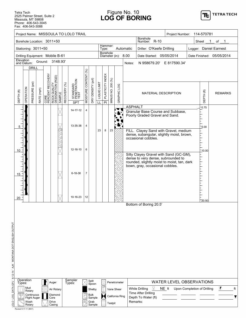
0.75
5.00
10.00
20.50
23 8
14-17-12
13-35-38
12-16-10
6-18-38
10-16-23
4
4
6
7
12
ASPHALTGranular Base Course and Subbase,Poorly Graded Gravel and Sand.
FILL. Clayey Sand with Gravel, mediumdense, subangular, slightly moist, brown,occasional cobbles.
Silty Clayey Gravel with Sand (GC-GM),dense to very dense, subrounded torounded, slightly moist to moist, tan, darkbown, gray, occasional cobbles.
Bottom of Boring 20.5'
23
SplitSpoon
Upon Completion of Drilling
Depth To Water (ft)
Driller:
Date Started:
DE
PT
H (
ft)
Vane Shear
LOG OF BORING
DRILL
California Ring
OP
ER
AT
ION
Logger:
R-10
8.00
WATER LEVEL OBSERVATIONS
1
5
10
15
20
RO
CK
QU
ALI
TY
DE
SIG
NA
TIO
N (
RQ
D)
Drilling Equipment:
BulkSample
Testpit
SamplerTypes:
3148.93'
of
MIN
US
NO
. 200
(%
)
SPTP
LAS
TIC
ITY
IND
EX
PI
Hammer:Type:
BoreholeNumber:
DriveCasing
Ground:
Project Name:
Borehole Location:
Stationing:
MudRotary
1
SA
MP
LE
RE
CO
VE
RY
(%
)
Penetrometer
PR
ES
SU
RE
(ps
i)
RA
TE
(m
ph)
Figure No. 10
LLLI
QU
ID L
IMIT
Elevationand Datum:
Shelby
3011+50
Date Finished:
Notes:
DE
PT
H (
ft)
ft
Auger
DiamondCore
ContinuousFlight Auger
WashRotary
Remarks:
N 958679.20' E 817590.34'
MO
IST
UR
E C
ON
TE
NT
(%
)
GrabSample
OperationTypes:
CO
RE
PE
RC
EN
T R
EC
OV
ER
Y
Time After Drilling
MATERIAL DESCRIPTION
ft
05/05/2014 05/05/2014
Automatic
REMARKS
Tetra Tech2525 Palmer Street, Suite 2Missoula, MT 59808Phone: 406-543-3045Fax: 406-543-3088
Sheet
LOLO
LO
G_D
AT
A.G
PJ
` 6-
12-
14
` A
JK `
MO
NT
AN
A D
OT
EN
GLI
SH
OU
TP
UT
114-570781
ST
AN
DA
RD
PE
NE
TR
AT
ION
TE
ST
O'Keefe Drilling
GR
AP
HIC
LO
G
DR
Y D
EN
SIT
Y (
pcf)
Air Rotary NEWhile Drilling
BoreholeDiameter (in):
Project Number:
Daniel Earnest
Revised 5-17-11 (MAT)
Mobile B-61
MISSOULA TO LOLO TRAIL
3011+50
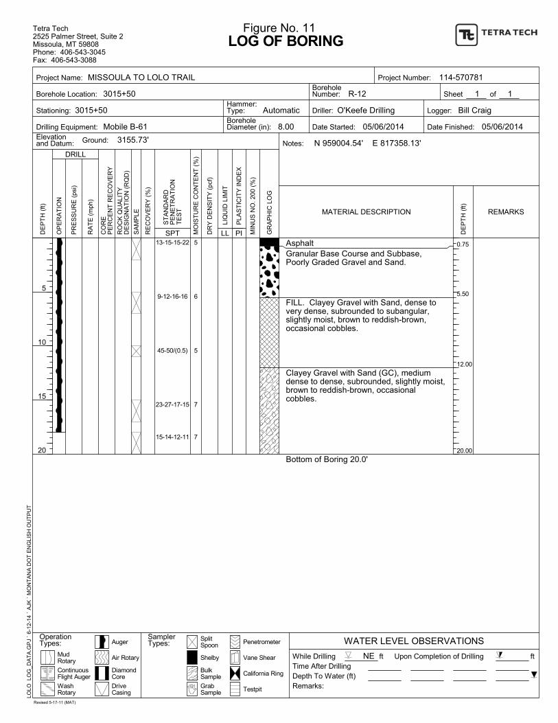
0.75
5.50
12.00
20.00
13-15-15-22
9-12-16-16
45-50/(0.5)
23-27-17-15
15-14-12-11
5
6
5
7
7
AsphaltGranular Base Course and Subbase,Poorly Graded Gravel and Sand.
FILL. Clayey Gravel with Sand, dense tovery dense, subrounded to subangular,slightly moist, brown to reddish-brown,occasional cobbles.
Clayey Gravel with Sand (GC), mediumdense to dense, subrounded, slightly moist,brown to reddish-brown, occasionalcobbles.
Bottom of Boring 20.0'
SplitSpoon
Upon Completion of Drilling
Depth To Water (ft)
Driller:
Date Started:
DE
PT
H (
ft)
Vane Shear
LOG OF BORING
DRILL
California Ring
OP
ER
AT
ION
Logger:
R-12
8.00
WATER LEVEL OBSERVATIONS
1
5
10
15
20
RO
CK
QU
ALI
TY
DE
SIG
NA
TIO
N (
RQ
D)
Drilling Equipment:
BulkSample
Testpit
SamplerTypes:
3155.73'
of
MIN
US
NO
. 200
(%
)
SPTP
LAS
TIC
ITY
IND
EX
PI
Hammer:Type:
BoreholeNumber:
DriveCasing
Ground:
Project Name:
Borehole Location:
Stationing:
MudRotary
1
SA
MP
LE
RE
CO
VE
RY
(%
)
Penetrometer
PR
ES
SU
RE
(ps
i)
RA
TE
(m
ph)
Figure No. 11
LLLI
QU
ID L
IMIT
Elevationand Datum:
Shelby
3015+50
Date Finished:
Notes:
DE
PT
H (
ft)
ft
Auger
DiamondCore
ContinuousFlight Auger
WashRotary
Remarks:
N 959004.54' E 817358.13'
MO
IST
UR
E C
ON
TE
NT
(%
)
GrabSample
OperationTypes:
CO
RE
PE
RC
EN
T R
EC
OV
ER
Y
Time After Drilling
MATERIAL DESCRIPTION
ft
05/06/2014 05/06/2014
Automatic
REMARKS
Tetra Tech2525 Palmer Street, Suite 2Missoula, MT 59808Phone: 406-543-3045Fax: 406-543-3088
Sheet
LOLO
LO
G_D
AT
A.G
PJ
` 6-
12-
14
` A
JK `
MO
NT
AN
A D
OT
EN
GLI
SH
OU
TP
UT
114-570781
ST
AN
DA
RD
PE
NE
TR
AT
ION
TE
ST
O'Keefe Drilling
GR
AP
HIC
LO
G
DR
Y D
EN
SIT
Y (
pcf)
Air Rotary NEWhile Drilling
BoreholeDiameter (in):
Project Number:
Bill Craig
Revised 5-17-11 (MAT)
Mobile B-61
MISSOULA TO LOLO TRAIL
3015+50
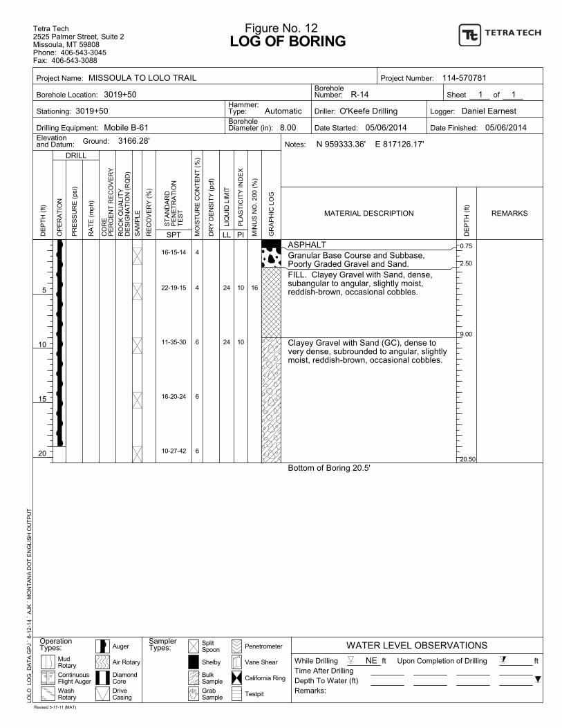
0.75
2.50
9.00
20.50
24
24
10
10
16-15-14
22-19-15
11-35-30
16-20-24
10-27-42
4
4
6
6
6
ASPHALTGranular Base Course and Subbase,Poorly Graded Gravel and Sand.FILL. Clayey Gravel with Sand, dense,subangular to angular, slightly moist,reddish-brown, occasional cobbles.
Clayey Gravel with Sand (GC), dense tovery dense, subrounded to angular, slightlymoist, reddish-brown, occasional cobbles.
Bottom of Boring 20.5'
16
SplitSpoon
Upon Completion of Drilling
Depth To Water (ft)
Driller:
Date Started:
DE
PT
H (
ft)
Vane Shear
LOG OF BORING
DRILL
California Ring
OP
ER
AT
ION
Logger:
R-14
8.00
WATER LEVEL OBSERVATIONS
1
5
10
15
20
RO
CK
QU
ALI
TY
DE
SIG
NA
TIO
N (
RQ
D)
Drilling Equipment:
BulkSample
Testpit
SamplerTypes:
3166.28'
of
MIN
US
NO
. 200
(%
)
SPTP
LAS
TIC
ITY
IND
EX
PI
Hammer:Type:
BoreholeNumber:
DriveCasing
Ground:
Project Name:
Borehole Location:
Stationing:
MudRotary
1
SA
MP
LE
RE
CO
VE
RY
(%
)
Penetrometer
PR
ES
SU
RE
(ps
i)
RA
TE
(m
ph)
Figure No. 12
LLLI
QU
ID L
IMIT
Elevationand Datum:
Shelby
3019+50
Date Finished:
Notes:
DE
PT
H (
ft)
ft
Auger
DiamondCore
ContinuousFlight Auger
WashRotary
Remarks:
N 959333.36' E 817126.17'
MO
IST
UR
E C
ON
TE
NT
(%
)
GrabSample
OperationTypes:
CO
RE
PE
RC
EN
T R
EC
OV
ER
Y
Time After Drilling
MATERIAL DESCRIPTION
ft
05/06/2014 05/06/2014
Automatic
REMARKS
Tetra Tech2525 Palmer Street, Suite 2Missoula, MT 59808Phone: 406-543-3045Fax: 406-543-3088
Sheet
LOLO
LO
G_D
AT
A.G
PJ
` 6-
12-
14
` A
JK `
MO
NT
AN
A D
OT
EN
GLI
SH
OU
TP
UT
114-570781
ST
AN
DA
RD
PE
NE
TR
AT
ION
TE
ST
O'Keefe Drilling
GR
AP
HIC
LO
G
DR
Y D
EN
SIT
Y (
pcf)
Air Rotary NEWhile Drilling
BoreholeDiameter (in):
Project Number:
Daniel Earnest
Revised 5-17-11 (MAT)
Mobile B-61
MISSOULA TO LOLO TRAIL
3019+50
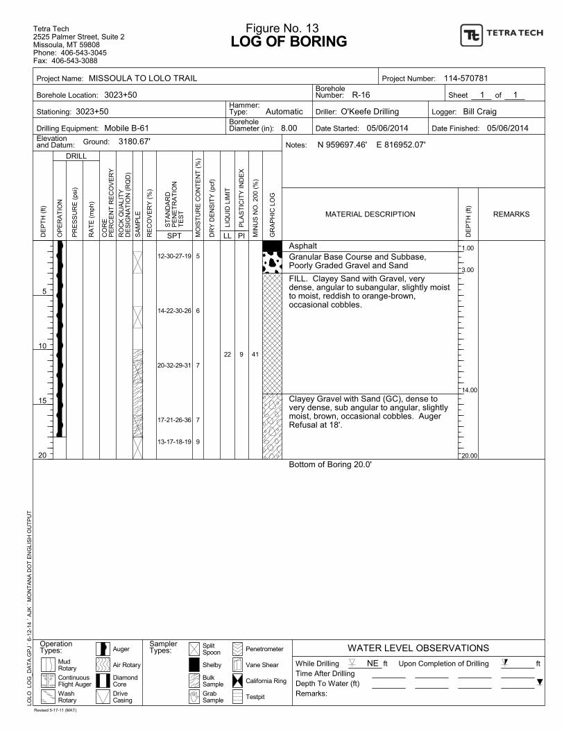
1.00
3.00
14.00
20.00
22 9
12-30-27-19
14-22-30-26
20-32-29-31
17-21-26-36
13-17-18-19
5
6
7
7
9
AsphaltGranular Base Course and Subbase,Poorly Graded Gravel and Sand
FILL. Clayey Sand with Gravel, verydense, angular to subangular, slightly moistto moist, reddish to orange-brown,occasional cobbles.
Clayey Gravel with Sand (GC), dense tovery dense, sub angular to angular, slightlymoist, brown, occasional cobbles. AugerRefusal at 18'.
Bottom of Boring 20.0'
41
SplitSpoon
Upon Completion of Drilling
Depth To Water (ft)
Driller:
Date Started:
DE
PT
H (
ft)
Vane Shear
LOG OF BORING
DRILL
California Ring
OP
ER
AT
ION
Logger:
R-16
8.00
WATER LEVEL OBSERVATIONS
1
5
10
15
20
RO
CK
QU
ALI
TY
DE
SIG
NA
TIO
N (
RQ
D)
Drilling Equipment:
BulkSample
Testpit
SamplerTypes:
3180.67'
of
MIN
US
NO
. 200
(%
)
SPTP
LAS
TIC
ITY
IND
EX
PI
Hammer:Type:
BoreholeNumber:
DriveCasing
Ground:
Project Name:
Borehole Location:
Stationing:
MudRotary
1
SA
MP
LE
RE
CO
VE
RY
(%
)
Penetrometer
PR
ES
SU
RE
(ps
i)
RA
TE
(m
ph)
Figure No. 13
LLLI
QU
ID L
IMIT
Elevationand Datum:
Shelby
3023+50
Date Finished:
Notes:
DE
PT
H (
ft)
ft
Auger
DiamondCore
ContinuousFlight Auger
WashRotary
Remarks:
N 959697.46' E 816952.07'
MO
IST
UR
E C
ON
TE
NT
(%
)
GrabSample
OperationTypes:
CO
RE
PE
RC
EN
T R
EC
OV
ER
Y
Time After Drilling
MATERIAL DESCRIPTION
ft
05/06/2014 05/06/2014
Automatic
REMARKS
Tetra Tech2525 Palmer Street, Suite 2Missoula, MT 59808Phone: 406-543-3045Fax: 406-543-3088
Sheet
LOLO
LO
G_D
AT
A.G
PJ
` 6-
12-
14
` A
JK `
MO
NT
AN
A D
OT
EN
GLI
SH
OU
TP
UT
114-570781
ST
AN
DA
RD
PE
NE
TR
AT
ION
TE
ST
O'Keefe Drilling
GR
AP
HIC
LO
G
DR
Y D
EN
SIT
Y (
pcf)
Air Rotary NEWhile Drilling
BoreholeDiameter (in):
Project Number:
Bill Craig
Revised 5-17-11 (MAT)
Mobile B-61
MISSOULA TO LOLO TRAIL
3023+50

0.67
3.00
21.00
25.50
22-23-26
13-23-28
13-15-21
26-31-21
11-15-18
11-16-12
4
6
8
6
7
8
ASPHALTGranular Base Course and Subbase,Poorly Graded Gravel and Sand
FILL. Clayey Sand with Gravel, mediumdense to very dense, subrounded tosubangular, slightly moist, brown toreddish-brown, occasional cobbles.
Clayey Sand with Gravel (SC), mediumdense to very dense, subrounded tosubangular, slightly moist, brown toreddish-brown, occasional cobbles. Veryhard drilling 21-24'
Bottom of Boring 25.5'
SplitSpoon
Upon Completion of Drilling
Depth To Water (ft)
Driller:
Date Started:
DE
PT
H (
ft)
Vane Shear
LOG OF BORING
DRILL
California Ring
OP
ER
AT
ION
Logger:
R-18
8.00
WATER LEVEL OBSERVATIONS
1
5
10
15
20
25
RO
CK
QU
ALI
TY
DE
SIG
NA
TIO
N (
RQ
D)
Drilling Equipment:
BulkSample
Testpit
SamplerTypes:
3217.19'
of
MIN
US
NO
. 200
(%
)
SPTP
LAS
TIC
ITY
IND
EX
PI
Hammer:Type:
BoreholeNumber:
DriveCasing
Ground:
Project Name:
Borehole Location:
Stationing:
MudRotary
1
SA
MP
LE
RE
CO
VE
RY
(%
)
Penetrometer
PR
ES
SU
RE
(ps
i)
RA
TE
(m
ph)
Figure No. 14
LLLI
QU
ID L
IMIT
Elevationand Datum:
Shelby
3036+50
Date Finished:
Notes:
DE
PT
H (
ft)
ft
Auger
DiamondCore
ContinuousFlight Auger
WashRotary
Remarks:
N 960957.28' E 817227.39'
MO
IST
UR
E C
ON
TE
NT
(%
)
GrabSample
OperationTypes:
CO
RE
PE
RC
EN
T R
EC
OV
ER
Y
Time After Drilling
MATERIAL DESCRIPTION
ft
05/16/2014 05/16/2014
Automatic
REMARKS
Tetra Tech2525 Palmer Street, Suite 2Missoula, MT 59808Phone: 406-543-3045Fax: 406-543-3088
Sheet
LOLO
LO
G_D
AT
A.G
PJ
` 6-
12-
14
` A
JK `
MO
NT
AN
A D
OT
EN
GLI
SH
OU
TP
UT
114-570781
ST
AN
DA
RD
PE
NE
TR
AT
ION
TE
ST
O'Keefe Drilling
GR
AP
HIC
LO
G
DR
Y D
EN
SIT
Y (
pcf)
Air Rotary NEWhile Drilling
BoreholeDiameter (in):
Project Number:
Daniel Earnest
Revised 5-17-11 (MAT)
Mobile B-61
MISSOULA TO LOLO TRAIL
3036+50
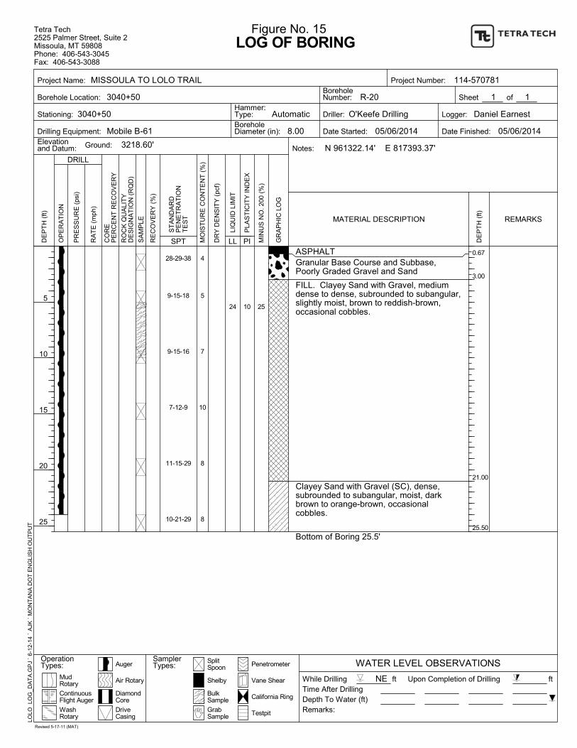
0.67
3.00
21.00
25.50
24 10
28-29-38
9-15-18
9-15-16
7-12-9
11-15-29
10-21-29
4
5
7
10
8
8
ASPHALTGranular Base Course and Subbase,Poorly Graded Gravel and Sand
FILL. Clayey Sand with Gravel, mediumdense to dense, subrounded to subangular,slightly moist, brown to reddish-brown,occasional cobbles.
Clayey Sand with Gravel (SC), dense,subrounded to subangular, moist, darkbrown to orange-brown, occasionalcobbles.
Bottom of Boring 25.5'
25
SplitSpoon
Upon Completion of Drilling
Depth To Water (ft)
Driller:
Date Started:
DE
PT
H (
ft)
Vane Shear
LOG OF BORING
DRILL
California Ring
OP
ER
AT
ION
Logger:
R-20
8.00
WATER LEVEL OBSERVATIONS
1
5
10
15
20
25
RO
CK
QU
ALI
TY
DE
SIG
NA
TIO
N (
RQ
D)
Drilling Equipment:
BulkSample
Testpit
SamplerTypes:
3218.60'
of
MIN
US
NO
. 200
(%
)
SPTP
LAS
TIC
ITY
IND
EX
PI
Hammer:Type:
BoreholeNumber:
DriveCasing
Ground:
Project Name:
Borehole Location:
Stationing:
MudRotary
1
SA
MP
LE
RE
CO
VE
RY
(%
)
Penetrometer
PR
ES
SU
RE
(ps
i)
RA
TE
(m
ph)
Figure No. 15
LLLI
QU
ID L
IMIT
Elevationand Datum:
Shelby
3040+50
Date Finished:
Notes:
DE
PT
H (
ft)
ft
Auger
DiamondCore
ContinuousFlight Auger
WashRotary
Remarks:
N 961322.14' E 817393.37'
MO
IST
UR
E C
ON
TE
NT
(%
)
GrabSample
OperationTypes:
CO
RE
PE
RC
EN
T R
EC
OV
ER
Y
Time After Drilling
MATERIAL DESCRIPTION
ft
05/06/2014 05/06/2014
Automatic
REMARKS
Tetra Tech2525 Palmer Street, Suite 2Missoula, MT 59808Phone: 406-543-3045Fax: 406-543-3088
Sheet
LOLO
LO
G_D
AT
A.G
PJ
` 6-
12-
14
` A
JK `
MO
NT
AN
A D
OT
EN
GLI
SH
OU
TP
UT
114-570781
ST
AN
DA
RD
PE
NE
TR
AT
ION
TE
ST
O'Keefe Drilling
GR
AP
HIC
LO
G
DR
Y D
EN
SIT
Y (
pcf)
Air Rotary NEWhile Drilling
BoreholeDiameter (in):
Project Number:
Daniel Earnest
Revised 5-17-11 (MAT)
Mobile B-61
MISSOULA TO LOLO TRAIL
3040+50
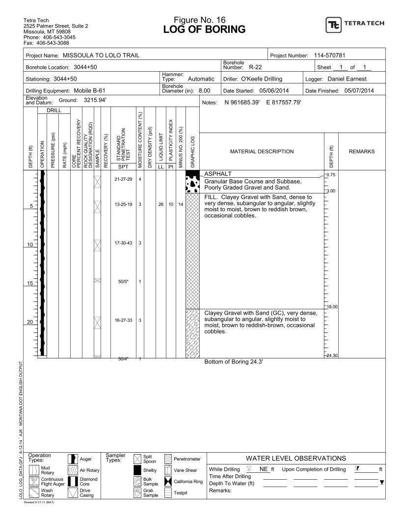
0.75
3.00
18.00
24.30
26 10
21-27-29
13-25-19
17-30-43
50/5"
16-27-33
50/4"
4
3
3
1
3
1
ASPHALTGranular Base Course and Subbase,Poorly Graded Gravel and Sand.
FILL. Clayey Gravel with Sand, dense tovery dense, subangular to angular, slightlymoist to moist, brown to reddish brown,occasional cobbles.
Clayey Gravel with Sand (GC), very dense,subangular to angular, slightly moist tomoist, brown to reddish-brown, occasionalcobbles.
Bottom of Boring 24.3'
14
SplitSpoon
Upon Completion of Drilling
Depth To Water (ft)
Driller:
Date Started:
DE
PT
H (
ft)
Vane Shear
LOG OF BORING
DRILL
California Ring
OP
ER
AT
ION
Logger:
R-22
8.00
WATER LEVEL OBSERVATIONS
1
5
10
15
20
RO
CK
QU
ALI
TY
DE
SIG
NA
TIO
N (
RQ
D)
Drilling Equipment:
BulkSample
Testpit
SamplerTypes:
3215.94'
of
MIN
US
NO
. 200
(%
)
SPTP
LAS
TIC
ITY
IND
EX
PI
Hammer:Type:
BoreholeNumber:
DriveCasing
Ground:
Project Name:
Borehole Location:
Stationing:
MudRotary
1
SA
MP
LE
RE
CO
VE
RY
(%
)
Penetrometer
PR
ES
SU
RE
(ps
i)
RA
TE
(m
ph)
Figure No. 16
LLLI
QU
ID L
IMIT
Elevationand Datum:
Shelby
3044+50
Date Finished:
Notes:
DE
PT
H (
ft)
ft
Auger
DiamondCore
ContinuousFlight Auger
WashRotary
Remarks:
N 961685.39' E 817557.79'
MO
IST
UR
E C
ON
TE
NT
(%
)
GrabSample
OperationTypes:
CO
RE
PE
RC
EN
T R
EC
OV
ER
Y
Time After Drilling
MATERIAL DESCRIPTION
ft
05/06/2014 05/07/2014
Automatic
REMARKS
Tetra Tech2525 Palmer Street, Suite 2Missoula, MT 59808Phone: 406-543-3045Fax: 406-543-3088
Sheet
LOLO
LO
G_D
AT
A.G
PJ
` 6-
12-
14
` A
JK `
MO
NT
AN
A D
OT
EN
GLI
SH
OU
TP
UT
114-570781
ST
AN
DA
RD
PE
NE
TR
AT
ION
TE
ST
O'Keefe Drilling
GR
AP
HIC
LO
G
DR
Y D
EN
SIT
Y (
pcf)
Air Rotary NEWhile Drilling
BoreholeDiameter (in):
Project Number:
Daniel Earnest
Revised 5-17-11 (MAT)
Mobile B-61
MISSOULA TO LOLO TRAIL
3044+50
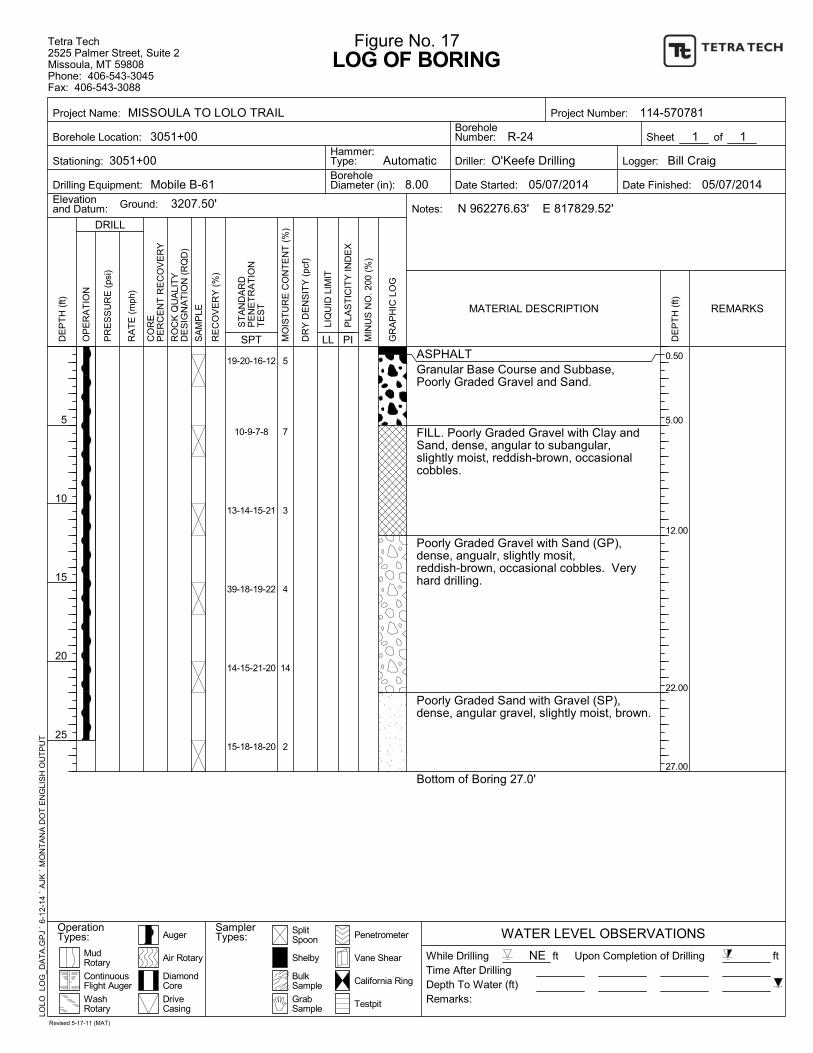
0.50
5.00
12.00
22.00
27.00
19-20-16-12
10-9-7-8
13-14-15-21
39-18-19-22
14-15-21-20
15-18-18-20
5
7
3
4
14
2
ASPHALTGranular Base Course and Subbase,Poorly Graded Gravel and Sand.
FILL. Poorly Graded Gravel with Clay andSand, dense, angular to subangular,slightly moist, reddish-brown, occasionalcobbles.
Poorly Graded Gravel with Sand (GP),dense, angualr, slightly mosit,reddish-brown, occasional cobbles. Veryhard drilling.
Poorly Graded Sand with Gravel (SP),dense, angular gravel, slightly moist, brown.
Bottom of Boring 27.0'
SplitSpoon
Upon Completion of Drilling
Depth To Water (ft)
Driller:
Date Started:
DE
PT
H (
ft)
Vane Shear
LOG OF BORING
DRILL
California Ring
OP
ER
AT
ION
Logger:
R-24
8.00
WATER LEVEL OBSERVATIONS
1
5
10
15
20
25
RO
CK
QU
ALI
TY
DE
SIG
NA
TIO
N (
RQ
D)
Drilling Equipment:
BulkSample
Testpit
SamplerTypes:
3207.50'
of
MIN
US
NO
. 200
(%
)
SPTP
LAS
TIC
ITY
IND
EX
PI
Hammer:Type:
BoreholeNumber:
DriveCasing
Ground:
Project Name:
Borehole Location:
Stationing:
MudRotary
1
SA
MP
LE
RE
CO
VE
RY
(%
)
Penetrometer
PR
ES
SU
RE
(ps
i)
RA
TE
(m
ph)
Figure No. 17
LLLI
QU
ID L
IMIT
Elevationand Datum:
Shelby
3051+00
Date Finished:
Notes:
DE
PT
H (
ft)
ft
Auger
DiamondCore
ContinuousFlight Auger
WashRotary
Remarks:
N 962276.63' E 817829.52'
MO
IST
UR
E C
ON
TE
NT
(%
)
GrabSample
OperationTypes:
CO
RE
PE
RC
EN
T R
EC
OV
ER
Y
Time After Drilling
MATERIAL DESCRIPTION
ft
05/07/2014 05/07/2014
Automatic
REMARKS
Tetra Tech2525 Palmer Street, Suite 2Missoula, MT 59808Phone: 406-543-3045Fax: 406-543-3088
Sheet
LOLO
LO
G_D
AT
A.G
PJ
` 6-
12-
14
` A
JK `
MO
NT
AN
A D
OT
EN
GLI
SH
OU
TP
UT
114-570781
ST
AN
DA
RD
PE
NE
TR
AT
ION
TE
ST
O'Keefe Drilling
GR
AP
HIC
LO
G
DR
Y D
EN
SIT
Y (
pcf)
Air Rotary NEWhile Drilling
BoreholeDiameter (in):
Project Number:
Bill Craig
Revised 5-17-11 (MAT)
Mobile B-61
MISSOULA TO LOLO TRAIL
3051+00
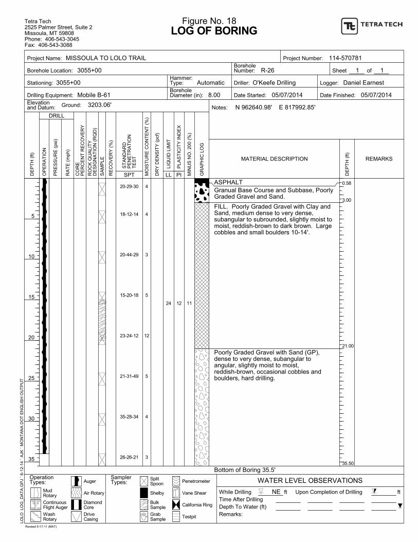
0.58
3.00
21.00
35.50
24 12
20-29-30
18-12-14
20-44-29
15-20-18
23-24-12
21-31-49
35-28-34
26-26-21
4
4
3
5
12
5
4
3
ASPHALTGranual Base Course and Subbase, PoorlyGraded Gravel and Sand.
FILL. Poorly Graded Gravel with Clay andSand, medium dense to very dense,subangular to subrounded, slightly moist tomoist, reddish-brown to dark brown. Largecobbles and small boulders 10-14'.
Poorly Graded Gravel with Sand (GP),dense to very dense, subangular toangular, slightly moist to moist,reddish-brown, occasional cobbles andboulders, hard drilling.
Bottom of Boring 35.5'
11
SplitSpoon
Upon Completion of Drilling
Depth To Water (ft)
Driller:
Date Started:
DE
PT
H (
ft)
Vane Shear
LOG OF BORING
DRILL
California Ring
OP
ER
AT
ION
Logger:
R-26
8.00
WATER LEVEL OBSERVATIONS
1
5
10
15
20
25
30
35
RO
CK
QU
ALI
TY
DE
SIG
NA
TIO
N (
RQ
D)
Drilling Equipment:
BulkSample
Testpit
SamplerTypes:
3203.06'
of
MIN
US
NO
. 200
(%
)
SPTP
LAS
TIC
ITY
IND
EX
PI
Hammer:Type:
BoreholeNumber:
DriveCasing
Ground:
Project Name:
Borehole Location:
Stationing:
MudRotary
1
SA
MP
LE
RE
CO
VE
RY
(%
)
Penetrometer
PR
ES
SU
RE
(ps
i)
RA
TE
(m
ph)
Figure No. 18
LLLI
QU
ID L
IMIT
Elevationand Datum:
Shelby
3055+00
Date Finished:
Notes:
DE
PT
H (
ft)
ft
Auger
DiamondCore
ContinuousFlight Auger
WashRotary
Remarks:
N 962640.98' E 817992.85'
MO
IST
UR
E C
ON
TE
NT
(%
)
GrabSample
OperationTypes:
CO
RE
PE
RC
EN
T R
EC
OV
ER
Y
Time After Drilling
MATERIAL DESCRIPTION
ft
05/07/2014 05/07/2014
Automatic
REMARKS
Tetra Tech2525 Palmer Street, Suite 2Missoula, MT 59808Phone: 406-543-3045Fax: 406-543-3088
Sheet
LOLO
LO
G_D
AT
A.G
PJ
` 6-
12-
14
` A
JK `
MO
NT
AN
A D
OT
EN
GLI
SH
OU
TP
UT
114-570781
ST
AN
DA
RD
PE
NE
TR
AT
ION
TE
ST
O'Keefe Drilling
GR
AP
HIC
LO
G
DR
Y D
EN
SIT
Y (
pcf)
Air Rotary NEWhile Drilling
BoreholeDiameter (in):
Project Number:
Daniel Earnest
Revised 5-17-11 (MAT)
Mobile B-61
MISSOULA TO LOLO TRAIL
3055+00
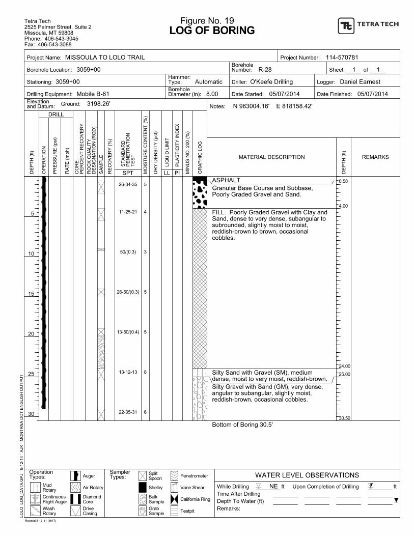
0.58
4.00
24.00
25.00
30.50
26-34-35
11-25-21
50/(0.3)
26-50/(0.3)
13-50/(0.4)
13-12-13
22-35-31
5
4
3
5
5
8
6
ASPHALTGranular Base Course and Subbase,Poorly Graded Gravel and Sand.
FILL. Poorly Graded Gravel with Clay andSand, dense to very dense, subangular tosubrounded, slightly moist to moist,reddish-brown to brown, occasionalcobbles.
Silty Sand with Gravel (SM), mediumdense, moist to very moist, reddish-brown.Silty Gravel with Sand (GM), very dense,angular to subangular, slightly moist,reddish-brown, occasional cobbles.
Bottom of Boring 30.5'
SplitSpoon
Upon Completion of Drilling
Depth To Water (ft)
Driller:
Date Started:
DE
PT
H (
ft)
Vane Shear
LOG OF BORING
DRILL
California Ring
OP
ER
AT
ION
Logger:
R-28
8.00
WATER LEVEL OBSERVATIONS
1
5
10
15
20
25
30
RO
CK
QU
ALI
TY
DE
SIG
NA
TIO
N (
RQ
D)
Drilling Equipment:
BulkSample
Testpit
SamplerTypes:
3198.26'
of
MIN
US
NO
. 200
(%
)
SPTP
LAS
TIC
ITY
IND
EX
PI
Hammer:Type:
BoreholeNumber:
DriveCasing
Ground:
Project Name:
Borehole Location:
Stationing:
MudRotary
1
SA
MP
LE
RE
CO
VE
RY
(%
)
Penetrometer
PR
ES
SU
RE
(ps
i)
RA
TE
(m
ph)
Figure No. 19
LLLI
QU
ID L
IMIT
Elevationand Datum:
Shelby
3059+00
Date Finished:
Notes:
DE
PT
H (
ft)
ft
Auger
DiamondCore
ContinuousFlight Auger
WashRotary
Remarks:
N 963004.16' E 818158.42'
MO
IST
UR
E C
ON
TE
NT
(%
)
GrabSample
OperationTypes:
CO
RE
PE
RC
EN
T R
EC
OV
ER
Y
Time After Drilling
MATERIAL DESCRIPTION
ft
05/07/2014 05/07/2014
Automatic
REMARKS
Tetra Tech2525 Palmer Street, Suite 2Missoula, MT 59808Phone: 406-543-3045Fax: 406-543-3088
Sheet
LOLO
LO
G_D
AT
A.G
PJ
` 6-
12-
14
` A
JK `
MO
NT
AN
A D
OT
EN
GLI
SH
OU
TP
UT
114-570781
ST
AN
DA
RD
PE
NE
TR
AT
ION
TE
ST
O'Keefe Drilling
GR
AP
HIC
LO
G
DR
Y D
EN
SIT
Y (
pcf)
Air Rotary NEWhile Drilling
BoreholeDiameter (in):
Project Number:
Daniel Earnest
Revised 5-17-11 (MAT)
Mobile B-61
MISSOULA TO LOLO TRAIL
3059+00
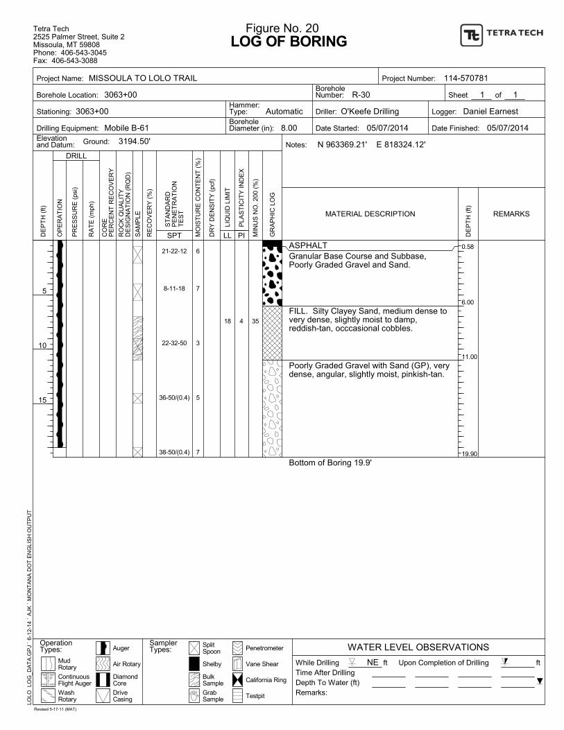
0.58
6.00
11.00
19.90
18 4
21-22-12
8-11-18
22-32-50
36-50/(0.4)
38-50/(0.4)
6
7
3
5
7
ASPHALTGranular Base Course and Subbase,Poorly Graded Gravel and Sand.
FILL. Silty Clayey Sand, medium dense tovery dense, slightly moist to damp,reddish-tan, occcasional cobbles.
Poorly Graded Gravel with Sand (GP), verydense, angular, slightly moist, pinkish-tan.
Bottom of Boring 19.9'
35
SplitSpoon
Upon Completion of Drilling
Depth To Water (ft)
Driller:
Date Started:
DE
PT
H (
ft)
Vane Shear
LOG OF BORING
DRILL
California Ring
OP
ER
AT
ION
Logger:
R-30
8.00
WATER LEVEL OBSERVATIONS
1
5
10
15
RO
CK
QU
ALI
TY
DE
SIG
NA
TIO
N (
RQ
D)
Drilling Equipment:
BulkSample
Testpit
SamplerTypes:
3194.50'
of
MIN
US
NO
. 200
(%
)
SPTP
LAS
TIC
ITY
IND
EX
PI
Hammer:Type:
BoreholeNumber:
DriveCasing
Ground:
Project Name:
Borehole Location:
Stationing:
MudRotary
1
SA
MP
LE
RE
CO
VE
RY
(%
)
Penetrometer
PR
ES
SU
RE
(ps
i)
RA
TE
(m
ph)
Figure No. 20
LLLI
QU
ID L
IMIT
Elevationand Datum:
Shelby
3063+00
Date Finished:
Notes:
DE
PT
H (
ft)
ft
Auger
DiamondCore
ContinuousFlight Auger
WashRotary
Remarks:
N 963369.21' E 818324.12'
MO
IST
UR
E C
ON
TE
NT
(%
)
GrabSample
OperationTypes:
CO
RE
PE
RC
EN
T R
EC
OV
ER
Y
Time After Drilling
MATERIAL DESCRIPTION
ft
05/07/2014 05/07/2014
Automatic
REMARKS
Tetra Tech2525 Palmer Street, Suite 2Missoula, MT 59808Phone: 406-543-3045Fax: 406-543-3088
Sheet
LOLO
LO
G_D
AT
A.G
PJ
` 6-
12-
14
` A
JK `
MO
NT
AN
A D
OT
EN
GLI
SH
OU
TP
UT
114-570781
ST
AN
DA
RD
PE
NE
TR
AT
ION
TE
ST
O'Keefe Drilling
GR
AP
HIC
LO
G
DR
Y D
EN
SIT
Y (
pcf)
Air Rotary NEWhile Drilling
BoreholeDiameter (in):
Project Number:
Daniel Earnest
Revised 5-17-11 (MAT)
Mobile B-61
MISSOULA TO LOLO TRAIL
3063+00
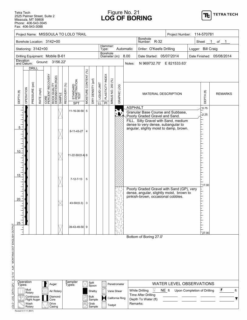
0.75
2.25
17.00
27.00
11-16-30-50
8-11-43-27
11-22-50/(0.4)
7-12-7-13
43-50/(0.3)
39-43-49-50
5
4
6
5
3
9
ASPHALTGranular Base Course and Subbase,Poorly Graded Gravel and Sand.FILL. Silty Gravel with Sand, mediumdense to very dense, subangular toangular, slighty moist to damp, brown.
Poorly Graded Gravel with Sand (GP), verydense, angular, slightly moist, brown topinkish-brown, occasional cobbles.
Bottom of Boring 27.0'
SplitSpoon
Upon Completion of Drilling
Depth To Water (ft)
Driller:
Date Started:
DE
PT
H (
ft)
Vane Shear
LOG OF BORING
DRILL
California Ring
OP
ER
AT
ION
Logger:
R-32
8.00
WATER LEVEL OBSERVATIONS
1
5
10
15
20
25
RO
CK
QU
ALI
TY
DE
SIG
NA
TIO
N (
RQ
D)
Drilling Equipment:
BulkSample
Testpit
SamplerTypes:
3156.22'
of
MIN
US
NO
. 200
(%
)
SPTP
LAS
TIC
ITY
IND
EX
PI
Hammer:Type:
BoreholeNumber:
DriveCasing
Ground:
Project Name:
Borehole Location:
Stationing:
MudRotary
1
SA
MP
LE
RE
CO
VE
RY
(%
)
Penetrometer
PR
ES
SU
RE
(ps
i)
RA
TE
(m
ph)
Figure No. 21
LLLI
QU
ID L
IMIT
Elevationand Datum:
Shelby
3142+00
Date Finished:
Notes:
DE
PT
H (
ft)
ft
Auger
DiamondCore
ContinuousFlight Auger
WashRotary
Remarks:
N 969732.70' E 821533.63'
MO
IST
UR
E C
ON
TE
NT
(%
)
GrabSample
OperationTypes:
CO
RE
PE
RC
EN
T R
EC
OV
ER
Y
Time After Drilling
MATERIAL DESCRIPTION
ft
05/07/2014 05/08/2014
Automatic
REMARKS
Tetra Tech2525 Palmer Street, Suite 2Missoula, MT 59808Phone: 406-543-3045Fax: 406-543-3088
Sheet
LOLO
LO
G_D
AT
A.G
PJ
` 6-
12-
14
` A
JK `
MO
NT
AN
A D
OT
EN
GLI
SH
OU
TP
UT
114-570781
ST
AN
DA
RD
PE
NE
TR
AT
ION
TE
ST
O'Keefe Drilling
GR
AP
HIC
LO
G
DR
Y D
EN
SIT
Y (
pcf)
Air Rotary NEWhile Drilling
BoreholeDiameter (in):
Project Number:
Bill Craig
Revised 5-17-11 (MAT)
Mobile B-61
MISSOULA TO LOLO TRAIL
3142+00
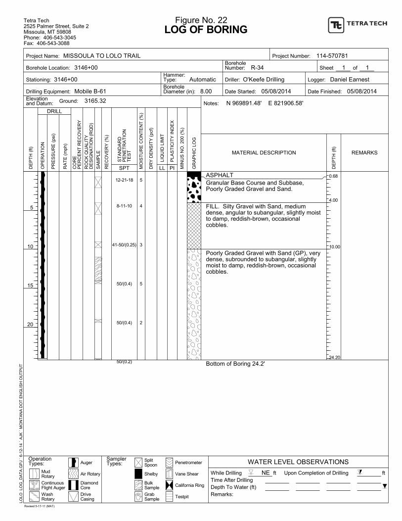
0.68
4.00
10.00
24.20
12-21-18
8-11-10
41-50/(0.25)
50/(0.4)
50/(0.4)
50/(0.2)
5
4
3
5
2
ASPHALTGranular Base Course and Subbase,Poorly Graded Gravel and Sand.
FILL. Silty Gravel with Sand, mediumdense, angular to subangular, slightly moistto damp, reddish-brown, occasionalcobbles.
Poorly Graded Gravel with Sand (GP), verydense, subrounded to subangular, slightlymoist to damp, reddish-brown, occasionalcobbles.
Bottom of Boring 24.2'
SplitSpoon
Upon Completion of Drilling
Depth To Water (ft)
Driller:
Date Started:
DE
PT
H (
ft)
Vane Shear
LOG OF BORING
DRILL
California Ring
OP
ER
AT
ION
Logger:
R-34
8.00
WATER LEVEL OBSERVATIONS
1
5
10
15
20
RO
CK
QU
ALI
TY
DE
SIG
NA
TIO
N (
RQ
D)
Drilling Equipment:
BulkSample
Testpit
SamplerTypes:
3165.32
of
MIN
US
NO
. 200
(%
)
SPTP
LAS
TIC
ITY
IND
EX
PI
Hammer:Type:
BoreholeNumber:
DriveCasing
Ground:
Project Name:
Borehole Location:
Stationing:
MudRotary
1
SA
MP
LE
RE
CO
VE
RY
(%
)
Penetrometer
PR
ES
SU
RE
(ps
i)
RA
TE
(m
ph)
Figure No. 22
LLLI
QU
ID L
IMIT
Elevationand Datum:
Shelby
3146+00
Date Finished:
Notes:
DE
PT
H (
ft)
ft
Auger
DiamondCore
ContinuousFlight Auger
WashRotary
Remarks:
N 969891.48' E 821906.58'
MO
IST
UR
E C
ON
TE
NT
(%
)
GrabSample
OperationTypes:
CO
RE
PE
RC
EN
T R
EC
OV
ER
Y
Time After Drilling
MATERIAL DESCRIPTION
ft
05/08/2014 05/08/2014
Automatic
REMARKS
Tetra Tech2525 Palmer Street, Suite 2Missoula, MT 59808Phone: 406-543-3045Fax: 406-543-3088
Sheet
LOLO
LO
G_D
AT
A.G
PJ
` 6-
12-
14
` A
JK `
MO
NT
AN
A D
OT
EN
GLI
SH
OU
TP
UT
114-570781
ST
AN
DA
RD
PE
NE
TR
AT
ION
TE
ST
O'Keefe Drilling
GR
AP
HIC
LO
G
DR
Y D
EN
SIT
Y (
pcf)
Air Rotary NEWhile Drilling
BoreholeDiameter (in):
Project Number:
Daniel Earnest
Revised 5-17-11 (MAT)
Mobile B-61
MISSOULA TO LOLO TRAIL
3146+00
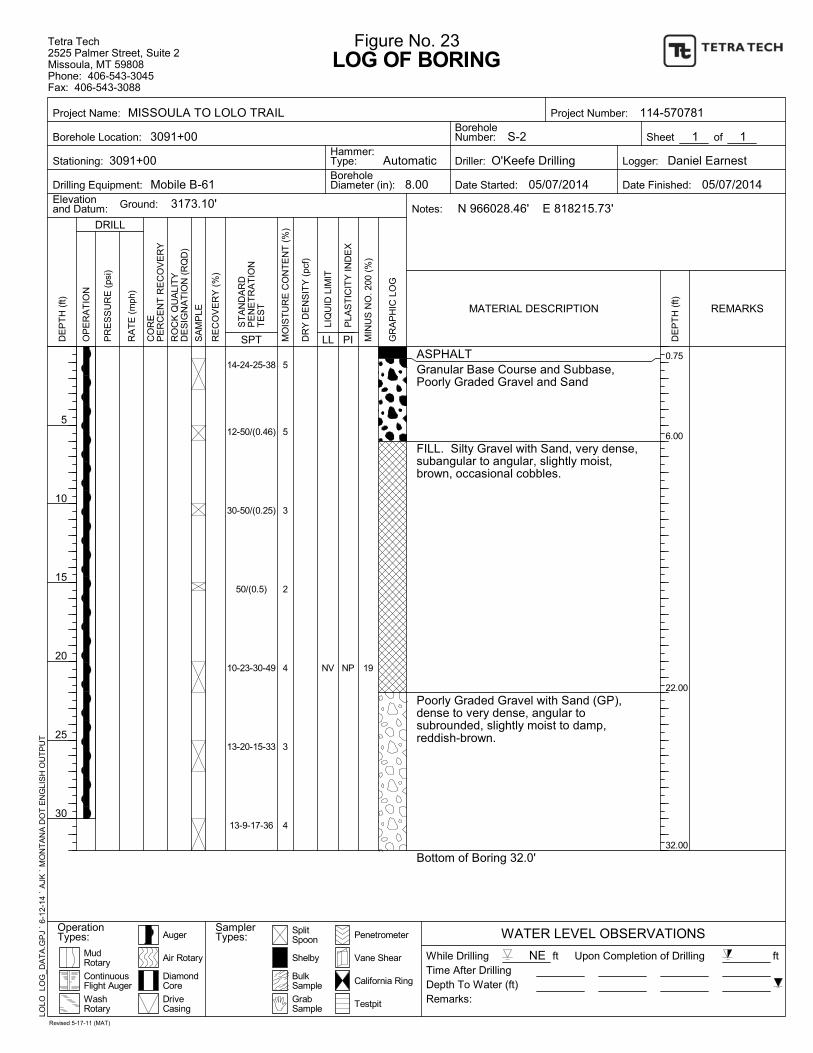
0.75
6.00
22.00
32.00
NV NP
14-24-25-38
12-50/(0.46)
30-50/(0.25)
50/(0.5)
10-23-30-49
13-20-15-33
13-9-17-36
5
5
3
2
4
3
4
ASPHALTGranular Base Course and Subbase,Poorly Graded Gravel and Sand
FILL. Silty Gravel with Sand, very dense,subangular to angular, slightly moist,brown, occasional cobbles.
Poorly Graded Gravel with Sand (GP),dense to very dense, angular tosubrounded, slightly moist to damp,reddish-brown.
Bottom of Boring 32.0'
19
SplitSpoon
Upon Completion of Drilling
Depth To Water (ft)
Driller:
Date Started:
DE
PT
H (
ft)
Vane Shear
LOG OF BORING
DRILL
California Ring
OP
ER
AT
ION
Logger:
S-2
8.00
WATER LEVEL OBSERVATIONS
1
5
10
15
20
25
30
RO
CK
QU
ALI
TY
DE
SIG
NA
TIO
N (
RQ
D)
Drilling Equipment:
BulkSample
Testpit
SamplerTypes:
3173.10'
of
MIN
US
NO
. 200
(%
)
SPTP
LAS
TIC
ITY
IND
EX
PI
Hammer:Type:
BoreholeNumber:
DriveCasing
Ground:
Project Name:
Borehole Location:
Stationing:
MudRotary
1
SA
MP
LE
RE
CO
VE
RY
(%
)
Penetrometer
PR
ES
SU
RE
(ps
i)
RA
TE
(m
ph)
Figure No. 23
LLLI
QU
ID L
IMIT
Elevationand Datum:
Shelby
3091+00
Date Finished:
Notes:
DE
PT
H (
ft)
ft
Auger
DiamondCore
ContinuousFlight Auger
WashRotary
Remarks:
N 966028.46' E 818215.73'
MO
IST
UR
E C
ON
TE
NT
(%
)
GrabSample
OperationTypes:
CO
RE
PE
RC
EN
T R
EC
OV
ER
Y
Time After Drilling
MATERIAL DESCRIPTION
ft
05/07/2014 05/07/2014
Automatic
REMARKS
Tetra Tech2525 Palmer Street, Suite 2Missoula, MT 59808Phone: 406-543-3045Fax: 406-543-3088
Sheet
LOLO
LO
G_D
AT
A.G
PJ
` 6-
12-
14
` A
JK `
MO
NT
AN
A D
OT
EN
GLI
SH
OU
TP
UT
114-570781
ST
AN
DA
RD
PE
NE
TR
AT
ION
TE
ST
O'Keefe Drilling
GR
AP
HIC
LO
G
DR
Y D
EN
SIT
Y (
pcf)
Air Rotary NEWhile Drilling
BoreholeDiameter (in):
Project Number:
Daniel Earnest
Revised 5-17-11 (MAT)
Mobile B-61
MISSOULA TO LOLO TRAIL
3091+00
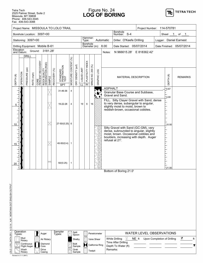
0.67
3.00
10.00
21.00
19 6
31-46-36
19-22-28
27-50/(0.25)
40-50/(0.4)
50/(0.25)
4
4
6
1
1
ASPHALTGranular Base Course and Subbase,Gravel and Sand.
FILL. Silty Clayer Gravel with Sand, denseto very dense, subangular to angular,slightly moist to moist, brown toreddish-brown, occasional cobbles.
Silty Gravel with Sand (GC-GM), verydense, subrounded to angular, slightlymoist, brown. Occasional cobbles andboulders, increasing with depth. Augerrefusal at 21'.
Bottom of Boring 21.0'
16
SplitSpoon
Upon Completion of Drilling
Depth To Water (ft)
Driller:
Date Started:
DE
PT
H (
ft)
Vane Shear
LOG OF BORING
DRILL
California Ring
OP
ER
AT
ION
Logger:
S-4
8.00
WATER LEVEL OBSERVATIONS
1
5
10
15
20
RO
CK
QU
ALI
TY
DE
SIG
NA
TIO
N (
RQ
D)
Drilling Equipment:
BulkSample
Testpit
SamplerTypes:
3181.28'
of
MIN
US
NO
. 200
(%
)
SPTP
LAS
TIC
ITY
IND
EX
PI
Hammer:Type:
BoreholeNumber:
DriveCasing
Ground:
Project Name:
Borehole Location:
Stationing:
MudRotary
1
SA
MP
LE
RE
CO
VE
RY
(%
)
Penetrometer
PR
ES
SU
RE
(ps
i)
RA
TE
(m
ph)
Figure No. 24
LLLI
QU
ID L
IMIT
Elevationand Datum:
Shelby
3097+00
Date Finished:
Notes:
DE
PT
H (
ft)
ft
Auger
DiamondCore
ContinuousFlight Auger
WashRotary
Remarks:
N 966615.28' E 818362.42'
MO
IST
UR
E C
ON
TE
NT
(%
)
GrabSample
OperationTypes:
CO
RE
PE
RC
EN
T R
EC
OV
ER
Y
Time After Drilling
MATERIAL DESCRIPTION
ft
05/07/2014 05/07/2014
Automatic
REMARKS
Tetra Tech2525 Palmer Street, Suite 2Missoula, MT 59808Phone: 406-543-3045Fax: 406-543-3088
Sheet
LOLO
LO
G_D
AT
A.G
PJ
` 6-
12-
14
` A
JK `
MO
NT
AN
A D
OT
EN
GLI
SH
OU
TP
UT
114-570781
ST
AN
DA
RD
PE
NE
TR
AT
ION
TE
ST
O'Keefe Drilling
GR
AP
HIC
LO
G
DR
Y D
EN
SIT
Y (
pcf)
Air Rotary NEWhile Drilling
BoreholeDiameter (in):
Project Number:
Daniel Earnest
Revised 5-17-11 (MAT)
Mobile B-61
MISSOULA TO LOLO TRAIL
3097+00

0
10
20
30
40
50
60
70
80
90
100
0.0010.010.1110100
25
Classification
GRAIN SIZE DISTRIBUTION
6030
COBBLES
Specimen Identification %Silt
8
56
104
14
GRAIN SIZE IN MILLIMETERS
506
D60
GRAVEL
2
LL
coarse
406
D30
2.299
D10 %Sand
200
25
5707
18 L
OG
S.G
PJ
` 6
-12
-14
` M
AT
` T
T_
US
GR
AIN
SIZ
E
BH-1 - (2 - 7 ft)
BH-1 - (2 - 7 ft)
PLSpecimen Identification
%Gravel
3
28
16 20
16
%Clay
SAND
143/8 100
PE
RC
EN
T F
INE
R B
Y W
EIG
HT
3/4 1/2
fine coarse
41
fine
1.5
SILT OR CLAY
6.931
1403
HYDROMETERU.S. SIEVE OPENING IN INCHES U.S. SIEVE NUMBERS
medium
CuPI
37.5
11
D100
Cc
Project:
Location: Refer to Site Map
Revised 1-23-08 (MAT)
Figure No. 25
CLAYEY GRAVEL with SAND(GC)
Lolo Bike Trail - Missoula County, Montana
Number: 114-570718
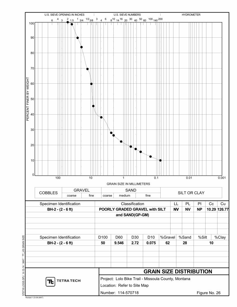
0
10
20
30
40
50
60
70
80
90
100
0.0010.010.1110100
NV
Classification
GRAIN SIZE DISTRIBUTION
6030
COBBLES
Specimen Identification %Silt
8
62
104
NV
GRAIN SIZE IN MILLIMETERS
506
D60
GRAVEL
2
LL
coarse
406
D30
2.72
D10
126.77
%Sand
200
NV
5707
18 L
OG
S.G
PJ
` 6
-12
-14
` M
AT
` T
T_
US
GR
AIN
SIZ
E
BH-2 - (2 - 6 ft)
BH-2 - (2 - 6 ft)
PLSpecimen Identification
10.29
%Gravel
3
28
16 20
10
%Clay
SAND
143/8 100
PE
RC
EN
T F
INE
R B
Y W
EIG
HT
3/4 1/2
fine coarse
41
0.075
fine
1.5
SILT OR CLAY
9.546
1403
HYDROMETERU.S. SIEVE OPENING IN INCHES U.S. SIEVE NUMBERS
medium
CuPI
50
NP
D100
Cc
Project:
Location: Refer to Site Map
Revised 1-23-08 (MAT)
Figure No. 26
POORLY GRADED GRAVEL with SILT
and SAND(GP-GM)
Lolo Bike Trail - Missoula County, Montana
Number: 114-570718
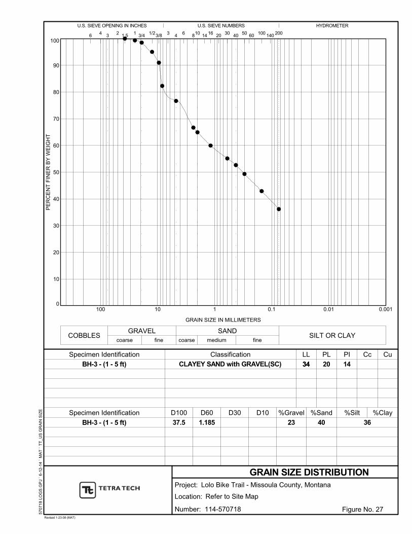
0
10
20
30
40
50
60
70
80
90
100
0.0010.010.1110100
34
Classification
GRAIN SIZE DISTRIBUTION
6030
COBBLES
Specimen Identification %Silt
8
23
104
20
GRAIN SIZE IN MILLIMETERS
506
D60
GRAVEL
2
LL
coarse
406
D30 D10 %Sand
200
34
5707
18 L
OG
S.G
PJ
` 6
-12
-14
` M
AT
` T
T_
US
GR
AIN
SIZ
E
BH-3 - (1 - 5 ft)
BH-3 - (1 - 5 ft)
PLSpecimen Identification
%Gravel
3
40
16 20
36
%Clay
SAND
143/8 100
PE
RC
EN
T F
INE
R B
Y W
EIG
HT
3/4 1/2
fine coarse
41
fine
1.5
SILT OR CLAY
1.185
1403
HYDROMETERU.S. SIEVE OPENING IN INCHES U.S. SIEVE NUMBERS
medium
CuPI
37.5
14
D100
Cc
Project:
Location: Refer to Site Map
Revised 1-23-08 (MAT)
Figure No. 27
CLAYEY SAND with GRAVEL(SC)
Lolo Bike Trail - Missoula County, Montana
Number: 114-570718

0
10
20
30
40
50
60
70
80
90
100
0.0010.010.1110100
24
Classification
GRAIN SIZE DISTRIBUTION
6030
COBBLES
Specimen Identification %Silt
8
33
104
15
GRAIN SIZE IN MILLIMETERS
506
D60
GRAVEL
2
LL
coarse
406
D30
0.081
D10 %Sand
200
24
5707
18 L
OG
S.G
PJ
` 6
-12
-14
` M
AT
` T
T_
US
GR
AIN
SIZ
E
BH-4 - (1 - 4 ft)
BH-4 - (1 - 4 ft)
PLSpecimen Identification
%Gravel
3
38
16 20
29
%Clay
SAND
143/8 100
PE
RC
EN
T F
INE
R B
Y W
EIG
HT
3/4 1/2
fine coarse
41
fine
1.5
SILT OR CLAY
2.977
1403
HYDROMETERU.S. SIEVE OPENING IN INCHES U.S. SIEVE NUMBERS
medium
CuPI
75
9
D100
Cc
Project:
Location: Refer to Site Map
Revised 1-23-08 (MAT)
Figure No. 28
CLAYEY SAND with GRAVEL(SC)
Lolo Bike Trail - Missoula County, Montana
Number: 114-570718

0
10
20
30
40
50
60
70
80
90
100
0.0010.010.1110100
23
Classification
GRAIN SIZE DISTRIBUTION
6030
COBBLES
Specimen Identification %Silt
8
18
104
13
GRAIN SIZE IN MILLIMETERS
506
D60
GRAVEL
2
LL
coarse
406
D30 D10 %Sand
200
23
5707
18 L
OG
S.G
PJ
` 6
-12
-14
` M
AT
` T
T_
US
GR
AIN
SIZ
E
BH-5 - (1 - 4 ft)
BH-5 - (1 - 4 ft)
PLSpecimen Identification
%Gravel
3
49
16 20
33
%Clay
SAND
143/8 100
PE
RC
EN
T F
INE
R B
Y W
EIG
HT
3/4 1/2
fine coarse
41
fine
1.5
SILT OR CLAY
0.672
1403
HYDROMETERU.S. SIEVE OPENING IN INCHES U.S. SIEVE NUMBERS
medium
CuPI
37.5
10
D100
Cc
Project:
Location: Refer to Site Map
Revised 1-23-08 (MAT)
Figure No. 29
CLAYEY SAND with GRAVEL(SC)
Lolo Bike Trail - Missoula County, Montana
Number: 114-570718
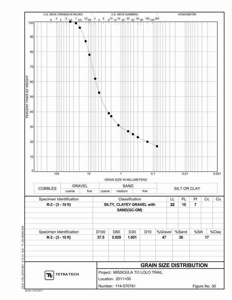
0
10
20
30
40
50
60
70
80
90
100
0.0010.010.1110100
22
Classification
GRAIN SIZE DISTRIBUTION
6030
COBBLES
Specimen Identification %Silt
8
47
104
15
GRAIN SIZE IN MILLIMETERS
506
D60
GRAVEL
2
LL
coarse
406
D30
1.001
D10 %Sand
200
22
LOLO
LO
G_D
AT
A.G
PJ
` 6-
12-
14
` A
JK `
TT
_U
S G
RA
IN S
IZE
R-2 - (3 - 10 ft)
R-2 - (3 - 10 ft)
PLSpecimen Identification
%Gravel
3
36
16 20
17
%Clay
SAND
143/8 100
PE
RC
EN
T F
INE
R B
Y W
EIG
HT
3/4 1/2
fine coarse
41
fine
1.5
SILT OR CLAY
5.929
1403
HYDROMETERU.S. SIEVE OPENING IN INCHES U.S. SIEVE NUMBERS
medium
CuPI
37.5
7
D100
Cc
Project:
Location: 2011+00
Revised 1-23-08 (MAT)
Figure No. 30
SILTY, CLAYEY GRAVEL with
SAND(GC-GM)
MISSOULA TO LOLO TRAIL
Number: 114-570781

0
10
20
30
40
50
60
70
80
90
100
0.0010.010.1110100
21
Classification
GRAIN SIZE DISTRIBUTION
6030
COBBLES
Specimen Identification %Silt
8
45
104
15
GRAIN SIZE IN MILLIMETERS
506
D60
GRAVEL
2
LL
coarse
406
D30
0.683
D10 %Sand
200
21
LOLO
LO
G_D
AT
A.G
PJ
` 6-
12-
14
` A
JK `
TT
_U
S G
RA
IN S
IZE
R-6 - (5 - 9 ft)
R-6 - (5 - 9 ft)
PLSpecimen Identification
%Gravel
3
37
16 20
18
%Clay
SAND
143/8 100
PE
RC
EN
T F
INE
R B
Y W
EIG
HT
3/4 1/2
fine coarse
41
fine
1.5
SILT OR CLAY
5.587
1403
HYDROMETERU.S. SIEVE OPENING IN INCHES U.S. SIEVE NUMBERS
medium
CuPI
25
6
D100
Cc
Project:
Location: 2021+00
Revised 1-23-08 (MAT)
Figure No. 31
SILTY, CLAYEY GRAVEL with
SAND(GC-GM)
MISSOULA TO LOLO TRAIL
Number: 114-570781

0
10
20
30
40
50
60
70
80
90
100
0.0010.010.1110100
NV
Classification
GRAIN SIZE DISTRIBUTION
6030
COBBLES
Specimen Identification %Silt
8
75
104
NV
GRAIN SIZE IN MILLIMETERS
506
D60
GRAVEL
2
LL
coarse
406
D30
6.006
D10
57.11
%Sand
200
NV
LOLO
LO
G_D
AT
A.G
PJ
` 6-
12-
14
` A
JK `
TT
_U
S G
RA
IN S
IZE
R-9 - (5 - 6.5 ft)
R-9 - (5 - 6.5 ft)
PLSpecimen Identification
12.17
%Gravel
3
19
16 20
6
%Clay
SAND
143/8 100
PE
RC
EN
T F
INE
R B
Y W
EIG
HT
3/4 1/2
fine coarse
41
0.228
fine
1.5
SILT OR CLAY
13.009
1403
HYDROMETERU.S. SIEVE OPENING IN INCHES U.S. SIEVE NUMBERS
medium
CuPI
75
NP
D100
Cc
Project:
Location: 2027+00
Revised 1-23-08 (MAT)
Figure No. 32
POORLY GRADED GRAVEL with SILT
and SAND(GP-GM)
MISSOULA TO LOLO TRAIL
Number: 114-570781
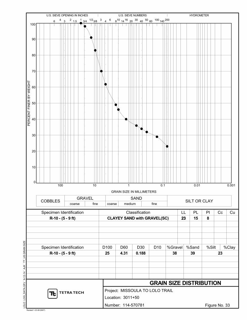
0
10
20
30
40
50
60
70
80
90
100
0.0010.010.1110100
23
Classification
GRAIN SIZE DISTRIBUTION
6030
COBBLES
Specimen Identification %Silt
8
38
104
15
GRAIN SIZE IN MILLIMETERS
506
D60
GRAVEL
2
LL
coarse
406
D30
0.188
D10 %Sand
200
23
LOLO
LO
G_D
AT
A.G
PJ
` 6-
12-
14
` A
JK `
TT
_U
S G
RA
IN S
IZE
R-10 - (5 - 9 ft)
R-10 - (5 - 9 ft)
PLSpecimen Identification
%Gravel
3
39
16 20
23
%Clay
SAND
143/8 100
PE
RC
EN
T F
INE
R B
Y W
EIG
HT
3/4 1/2
fine coarse
41
fine
1.5
SILT OR CLAY
4.31
1403
HYDROMETERU.S. SIEVE OPENING IN INCHES U.S. SIEVE NUMBERS
medium
CuPI
25
8
D100
Cc
Project:
Location: 3011+50
Revised 1-23-08 (MAT)
Figure No. 33
CLAYEY SAND with GRAVEL(SC)
MISSOULA TO LOLO TRAIL
Number: 114-570781
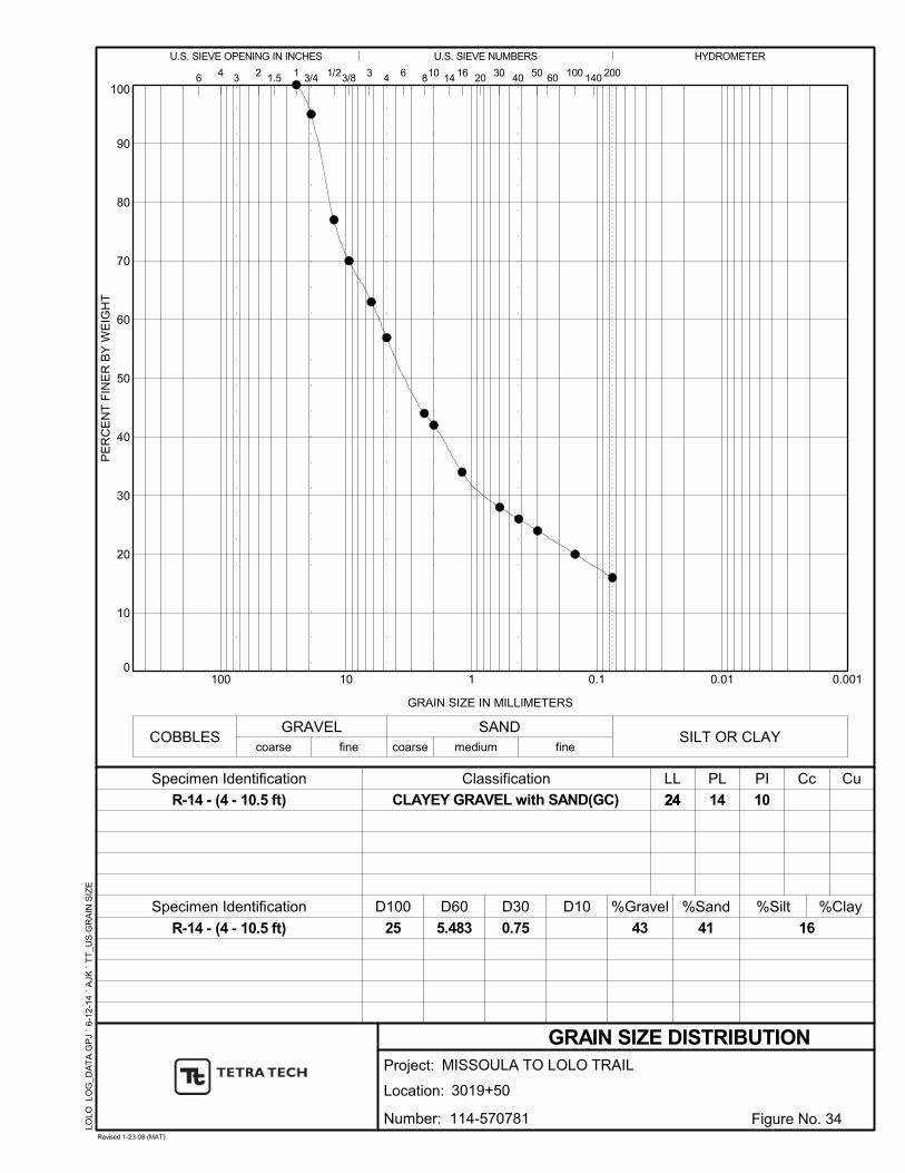
0
10
20
30
40
50
60
70
80
90
100
0.0010.010.1110100
24
Classification
GRAIN SIZE DISTRIBUTION
6030
COBBLES
Specimen Identification %Silt
8
43
104
14
GRAIN SIZE IN MILLIMETERS
506
D60
GRAVEL
2
LL
coarse
406
D30
0.75
D10 %Sand
200
24
LOLO
LO
G_D
AT
A.G
PJ
` 6-
12-
14
` A
JK `
TT
_U
S G
RA
IN S
IZE
R-14 - (4 - 10.5 ft)
R-14 - (4 - 10.5 ft)
PLSpecimen Identification
%Gravel
3
41
16 20
16
%Clay
SAND
143/8 100
PE
RC
EN
T F
INE
R B
Y W
EIG
HT
3/4 1/2
fine coarse
41
fine
1.5
SILT OR CLAY
5.483
1403
HYDROMETERU.S. SIEVE OPENING IN INCHES U.S. SIEVE NUMBERS
medium
CuPI
25
10
D100
Cc
Project:
Location: 3019+50
Revised 1-23-08 (MAT)
Figure No. 34
CLAYEY GRAVEL with SAND(GC)
MISSOULA TO LOLO TRAIL
Number: 114-570781
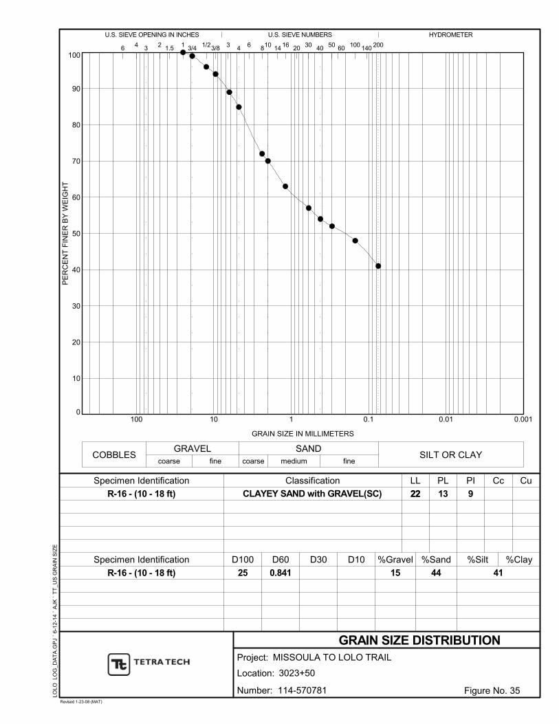
0
10
20
30
40
50
60
70
80
90
100
0.0010.010.1110100
22
Classification
GRAIN SIZE DISTRIBUTION
6030
COBBLES
Specimen Identification %Silt
8
15
104
13
GRAIN SIZE IN MILLIMETERS
506
D60
GRAVEL
2
LL
coarse
406
D30 D10 %Sand
200
22
LOLO
LO
G_D
AT
A.G
PJ
` 6-
12-
14
` A
JK `
TT
_U
S G
RA
IN S
IZE
R-16 - (10 - 18 ft)
R-16 - (10 - 18 ft)
PLSpecimen Identification
%Gravel
3
44
16 20
41
%Clay
SAND
143/8 100
PE
RC
EN
T F
INE
R B
Y W
EIG
HT
3/4 1/2
fine coarse
41
fine
1.5
SILT OR CLAY
0.841
1403
HYDROMETERU.S. SIEVE OPENING IN INCHES U.S. SIEVE NUMBERS
medium
CuPI
25
9
D100
Cc
Project:
Location: 3023+50
Revised 1-23-08 (MAT)
Figure No. 35
CLAYEY SAND with GRAVEL(SC)
MISSOULA TO LOLO TRAIL
Number: 114-570781
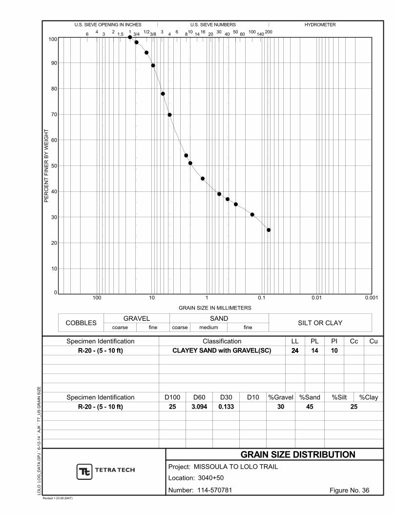
0
10
20
30
40
50
60
70
80
90
100
0.0010.010.1110100
24
Classification
GRAIN SIZE DISTRIBUTION
6030
COBBLES
Specimen Identification %Silt
8
30
104
14
GRAIN SIZE IN MILLIMETERS
506
D60
GRAVEL
2
LL
coarse
406
D30
0.133
D10 %Sand
200
24
LOLO
LO
G_D
AT
A.G
PJ
` 6-
12-
14
` A
JK `
TT
_U
S G
RA
IN S
IZE
R-20 - (5 - 10 ft)
R-20 - (5 - 10 ft)
PLSpecimen Identification
%Gravel
3
45
16 20
25
%Clay
SAND
143/8 100
PE
RC
EN
T F
INE
R B
Y W
EIG
HT
3/4 1/2
fine coarse
41
fine
1.5
SILT OR CLAY
3.094
1403
HYDROMETERU.S. SIEVE OPENING IN INCHES U.S. SIEVE NUMBERS
medium
CuPI
25
10
D100
Cc
Project:
Location: 3040+50
Revised 1-23-08 (MAT)
Figure No. 36
CLAYEY SAND with GRAVEL(SC)
MISSOULA TO LOLO TRAIL
Number: 114-570781
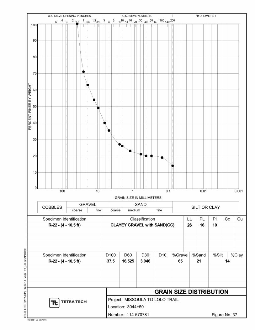
0
10
20
30
40
50
60
70
80
90
100
0.0010.010.1110100
26
Classification
GRAIN SIZE DISTRIBUTION
6030
COBBLES
Specimen Identification %Silt
8
65
104
16
GRAIN SIZE IN MILLIMETERS
506
D60
GRAVEL
2
LL
coarse
406
D30
3.046
D10 %Sand
200
26
LOLO
LO
G_D
AT
A.G
PJ
` 6-
12-
14
` A
JK `
TT
_U
S G
RA
IN S
IZE
R-22 - (4 - 10.5 ft)
R-22 - (4 - 10.5 ft)
PLSpecimen Identification
%Gravel
3
21
16 20
14
%Clay
SAND
143/8 100
PE
RC
EN
T F
INE
R B
Y W
EIG
HT
3/4 1/2
fine coarse
41
fine
1.5
SILT OR CLAY
16.525
1403
HYDROMETERU.S. SIEVE OPENING IN INCHES U.S. SIEVE NUMBERS
medium
CuPI
37.5
10
D100
Cc
Project:
Location: 3044+50
Revised 1-23-08 (MAT)
Figure No. 37
CLAYEY GRAVEL with SAND(GC)
MISSOULA TO LOLO TRAIL
Number: 114-570781

0
10
20
30
40
50
60
70
80
90
100
0.0010.010.1110100
24
Classification
GRAIN SIZE DISTRIBUTION
6030
COBBLES
Specimen Identification %Silt
8
67
104
12
GRAIN SIZE IN MILLIMETERS
506
D60
GRAVEL
2
LL
coarse
406
D30
4.218
D10
144.20
%Sand
200
24
LOLO
LO
G_D
AT
A.G
PJ
` 6-
12-
14
` A
JK `
TT
_U
S G
RA
IN S
IZE
R-26 - (15 - 20 ft)
R-26 - (15 - 20 ft)
PLSpecimen Identification
43.57
%Gravel
3
22
16 20
11
%Clay
SAND
143/8 100
PE
RC
EN
T F
INE
R B
Y W
EIG
HT
3/4 1/2
fine coarse
41
fine
1.5
SILT OR CLAY
7.673
1403
HYDROMETERU.S. SIEVE OPENING IN INCHES U.S. SIEVE NUMBERS
medium
CuPI
25
12
D100
Cc
Project:
Location: 3055+00
Revised 1-23-08 (MAT)
Figure No. 38
POORLY GRADED GRAVEL with CLAY
and SAND(GP-GC)
MISSOULA TO LOLO TRAIL
Number: 114-570781

0
10
20
30
40
50
60
70
80
90
100
0.0010.010.1110100
18
Classification
GRAIN SIZE DISTRIBUTION
6030
COBBLES
Specimen Identification %Silt
8
13
104
14
GRAIN SIZE IN MILLIMETERS
506
D60
GRAVEL
2
LL
coarse
406
D30 D10 %Sand
200
18
LOLO
LO
G_D
AT
A.G
PJ
` 6-
12-
14
` A
JK `
TT
_U
S G
RA
IN S
IZE
R-30 - (7 - 11 ft)
R-30 - (7 - 11 ft)
PLSpecimen Identification
%Gravel
3
52
16 20
35
%Clay
SAND
143/8 100
PE
RC
EN
T F
INE
R B
Y W
EIG
HT
3/4 1/2
fine coarse
41
fine
1.5
SILT OR CLAY
0.668
1403
HYDROMETERU.S. SIEVE OPENING IN INCHES U.S. SIEVE NUMBERS
medium
CuPI
19
4
D100
Cc
Project:
Location: 3063+00
Revised 1-23-08 (MAT)
Figure No. 39
SILTY, CLAYEY SAND(SC-SM)
MISSOULA TO LOLO TRAIL
Number: 114-570781
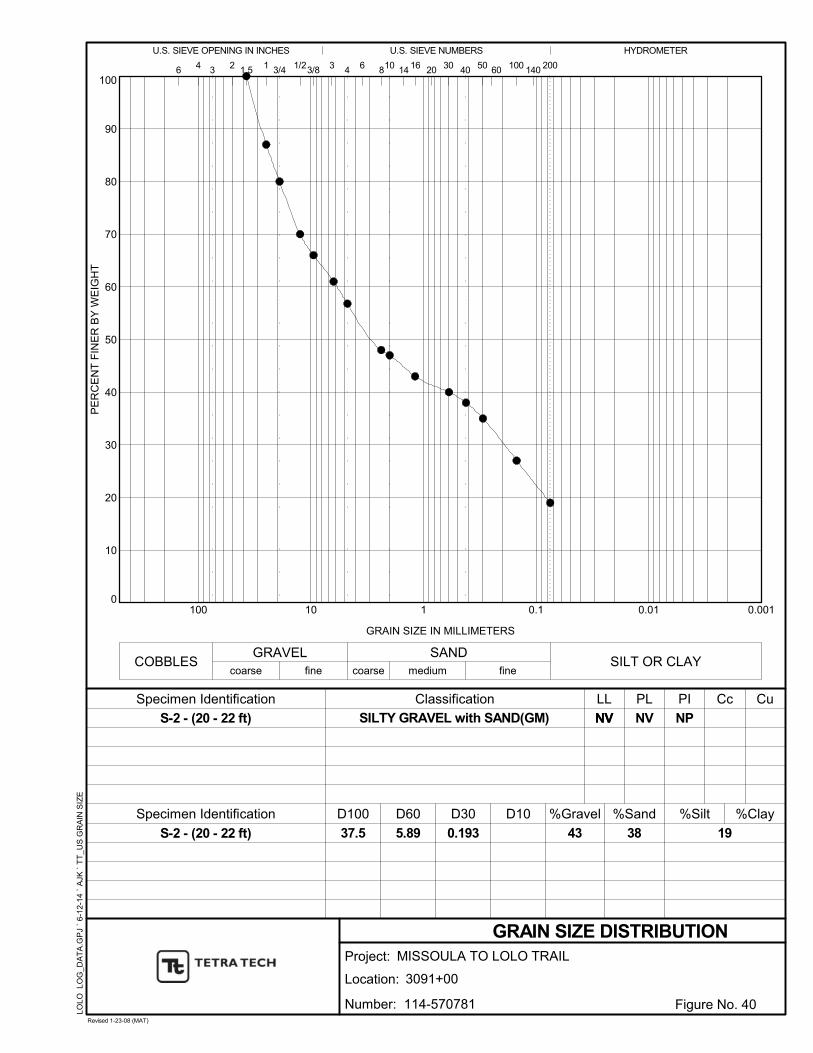
0
10
20
30
40
50
60
70
80
90
100
0.0010.010.1110100
NV
Classification
GRAIN SIZE DISTRIBUTION
6030
COBBLES
Specimen Identification %Silt
8
43
104
NV
GRAIN SIZE IN MILLIMETERS
506
D60
GRAVEL
2
LL
coarse
406
D30
0.193
D10 %Sand
200
NV
LOLO
LO
G_D
AT
A.G
PJ
` 6-
12-
14
` A
JK `
TT
_U
S G
RA
IN S
IZE
S-2 - (20 - 22 ft)
S-2 - (20 - 22 ft)
PLSpecimen Identification
%Gravel
3
38
16 20
19
%Clay
SAND
143/8 100
PE
RC
EN
T F
INE
R B
Y W
EIG
HT
3/4 1/2
fine coarse
41
fine
1.5
SILT OR CLAY
5.89
1403
HYDROMETERU.S. SIEVE OPENING IN INCHES U.S. SIEVE NUMBERS
medium
CuPI
37.5
NP
D100
Cc
Project:
Location: 3091+00
Revised 1-23-08 (MAT)
Figure No. 40
SILTY GRAVEL with SAND(GM)
MISSOULA TO LOLO TRAIL
Number: 114-570781
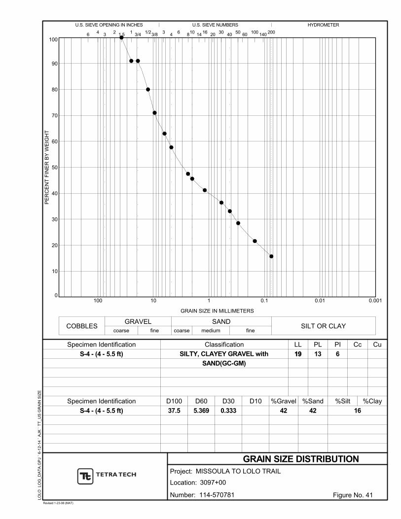
0
10
20
30
40
50
60
70
80
90
100
0.0010.010.1110100
19
Classification
GRAIN SIZE DISTRIBUTION
6030
COBBLES
Specimen Identification %Silt
8
42
104
13
GRAIN SIZE IN MILLIMETERS
506
D60
GRAVEL
2
LL
coarse
406
D30
0.333
D10 %Sand
200
19
LOLO
LO
G_D
AT
A.G
PJ
` 6-
12-
14
` A
JK `
TT
_U
S G
RA
IN S
IZE
S-4 - (4 - 5.5 ft)
S-4 - (4 - 5.5 ft)
PLSpecimen Identification
%Gravel
3
42
16 20
16
%Clay
SAND
143/8 100
PE
RC
EN
T F
INE
R B
Y W
EIG
HT
3/4 1/2
fine coarse
41
fine
1.5
SILT OR CLAY
5.369
1403
HYDROMETERU.S. SIEVE OPENING IN INCHES U.S. SIEVE NUMBERS
medium
CuPI
37.5
6
D100
Cc
Project:
Location: 3097+00
Revised 1-23-08 (MAT)
Figure No. 41
SILTY, CLAYEY GRAVEL with
SAND(GC-GM)
MISSOULA TO LOLO TRAIL
Number: 114-570781

0
10
20
30
40
50
60
70
80
90
100
0.0010.010.1110100
Classification
GRAIN SIZE DISTRIBUTION
6030
COBBLES
Specimen Identification %Silt
8
58
104
GRAIN SIZE IN MILLIMETERS
506
D60
GRAVEL
2
LL
coarse
406
D30
2.113
D10
16.78
%Sand
200
5707
18 L
OG
S.G
PJ
` 6
-12
-14
` M
AT
` T
T_
US
GR
AIN
SIZ
E
RAP-N - (0 - ft)
RAP-N - (0 - ft)
PLSpecimen Identification
1.19
%Gravel
3
38
16 20
4
%Clay
SAND
143/8 100
PE
RC
EN
T F
INE
R B
Y W
EIG
HT
3/4 1/2
fine coarse
41
0.473
fine
1.5
SILT OR CLAY
7.937
1403
HYDROMETERU.S. SIEVE OPENING IN INCHES U.S. SIEVE NUMBERS
medium
CuPI
50
D100
Cc
Project:
Location: Northeast Side of Stockpile
Revised 1-23-08 (MAT)
Figure No. 42
WELL-GRADED GRAVEL with
SAND(GW)
Lolo Bike Trail - Missoula County, Montana
Number: 114-570718

0
10
20
30
40
50
60
70
80
90
100
0.0010.010.1110100
Classification
GRAIN SIZE DISTRIBUTION
6030
COBBLES
Specimen Identification %Silt
8
60
104
GRAIN SIZE IN MILLIMETERS
506
D60
GRAVEL
2
LL
coarse
406
D30
2.233
D10
18.62
%Sand
200
5707
18 L
OG
S.G
PJ
` 6
-12
-14
` M
AT
` T
T_
US
GR
AIN
SIZ
E
RAP-S - (0 - ft)
RAP-S - (0 - ft)
PLSpecimen Identification
1.48
%Gravel
3
35
16 20
5
%Clay
SAND
143/8 100
PE
RC
EN
T F
INE
R B
Y W
EIG
HT
3/4 1/2
fine coarse
41
0.425
fine
1.5
SILT OR CLAY
7.915
1403
HYDROMETERU.S. SIEVE OPENING IN INCHES U.S. SIEVE NUMBERS
medium
CuPI
50
D100
Cc
Project:
Location: South Side of Stockpile
Revised 1-23-08 (MAT)
Figure No. 43
WELL-GRADED GRAVEL with
SAND(GW)
Lolo Bike Trail - Missoula County, Montana
Number: 114-570718
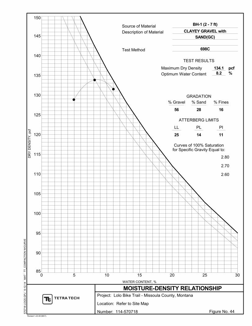
85
90
95
100
105
110
115
120
125
130
135
140
145
150
0 5 10 15 20 25 30
LL
GRADATION
25 11
PL
14
Curves of 100% Saturationfor Specific Gravity Equal to:
2.80
2.70
2.60
PI
Optimum Water Content
Test Method 698C
134.18.2
% Gravel
28
ATTERBERG LIMITS
56
% Sand % Fines
16
WATER CONTENT, %
Source of Material
Description of MaterialD
RY
DE
NS
ITY
, pc
f
pcf%
TEST RESULTS
5707
18 L
OG
S.G
PJ
` 6
-12
-14
` M
AT
` T
T_
CO
MP
AC
TIO
N W
/CU
RV
EBH-1 (2 - 7 ft)
Project:
Location:
MOISTURE-DENSITY RELATIONSHIP
Refer to Site Map
Figure No. 44Revised 1-23-08 (MAT)
Lolo Bike Trail - Missoula County, Montana
CLAYEY GRAVEL with
SAND(GC)
Number: 114-570718
Maximum Dry Density
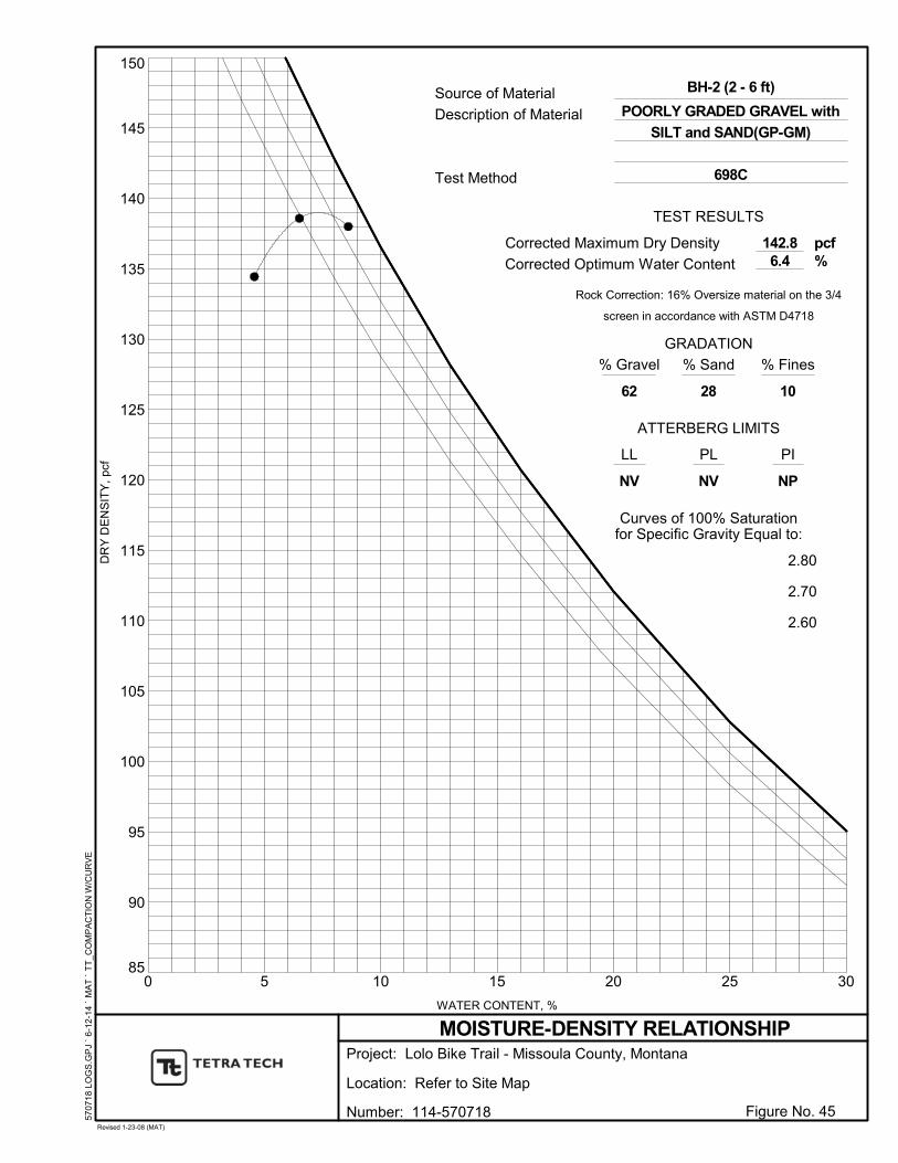
85
90
95
100
105
110
115
120
125
130
135
140
145
150
0 5 10 15 20 25 30
LL
GRADATION
NV NP
PL
NV
Rock Correction: 16% Oversize material on the 3/4
screen in accordance with ASTM D4718
Curves of 100% Saturationfor Specific Gravity Equal to:
2.80
2.70
2.60
PI
Corrected Optimum Water Content
Test Method 698C
142.86.4
% Gravel
28
ATTERBERG LIMITS
62
% Sand % Fines
10
WATER CONTENT, %
Source of Material
Description of MaterialD
RY
DE
NS
ITY
, pc
f
pcf%
TEST RESULTS
5707
18 L
OG
S.G
PJ
` 6
-12
-14
` M
AT
` T
T_
CO
MP
AC
TIO
N W
/CU
RV
EBH-2 (2 - 6 ft)
Project:
Location:
MOISTURE-DENSITY RELATIONSHIP
Refer to Site Map
Figure No. 45Revised 1-23-08 (MAT)
Lolo Bike Trail - Missoula County, Montana
POORLY GRADED GRAVEL with
SILT and SAND(GP-GM)
Number: 114-570718
Corrected Maximum Dry Density

85
90
95
100
105
110
115
120
125
130
135
140
145
150
0 5 10 15 20 25 30
LL
GRADATION
34 14
PL
20
Rock Correction: 23% Oversize material on the #4
screen in accordance with ASTM D4718
Curves of 100% Saturationfor Specific Gravity Equal to:
2.80
2.70
2.60
PI
Corrected Optimum Water Content
Test Method 698A
123.810.6
% Gravel
40
ATTERBERG LIMITS
23
% Sand % Fines
36
WATER CONTENT, %
Source of Material
Description of MaterialD
RY
DE
NS
ITY
, pc
f
pcf%
TEST RESULTS
5707
18 L
OG
S.G
PJ
` 6
-12
-14
` M
AT
` T
T_
CO
MP
AC
TIO
N W
/CU
RV
EBH-3 (1 - 5 ft)
Project:
Location:
MOISTURE-DENSITY RELATIONSHIP
Refer to Site Map
Figure No. 46Revised 1-23-08 (MAT)
Lolo Bike Trail - Missoula County, Montana
CLAYEY SAND with
GRAVEL(SC)
Number: 114-570718
Corrected Maximum Dry Density
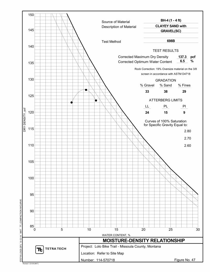
85
90
95
100
105
110
115
120
125
130
135
140
145
150
0 5 10 15 20 25 30
LL
GRADATION
24 9
PL
15
Rock Correction: 19% Oversize material on the 3/8
screen in accordance with ASTM D4718
Curves of 100% Saturationfor Specific Gravity Equal to:
2.80
2.70
2.60
PI
Corrected Optimum Water Content
Test Method 698B
137.36.5
% Gravel
38
ATTERBERG LIMITS
33
% Sand % Fines
29
WATER CONTENT, %
Source of Material
Description of MaterialD
RY
DE
NS
ITY
, pc
f
pcf%
TEST RESULTS
5707
18 L
OG
S.G
PJ
` 6
-12
-14
` M
AT
` T
T_
CO
MP
AC
TIO
N W
/CU
RV
EBH-4 (1 - 4 ft)
Project:
Location:
MOISTURE-DENSITY RELATIONSHIP
Refer to Site Map
Figure No. 47Revised 1-23-08 (MAT)
Lolo Bike Trail - Missoula County, Montana
CLAYEY SAND with
GRAVEL(SC)
Number: 114-570718
Corrected Maximum Dry Density

85
90
95
100
105
110
115
120
125
130
135
140
145
150
0 5 10 15 20 25 30
LL
GRADATION
23 10
PL
13
Curves of 100% Saturationfor Specific Gravity Equal to:
2.80
2.70
2.60
PI
Optimum Water Content
Test Method 698A
126.39.7
% Gravel
49
ATTERBERG LIMITS
18
% Sand % Fines
33
WATER CONTENT, %
Source of Material
Description of MaterialD
RY
DE
NS
ITY
, pc
f
pcf%
TEST RESULTS
5707
18 L
OG
S.G
PJ
` 6
-12
-14
` M
AT
` T
T_
CO
MP
AC
TIO
N W
/CU
RV
EBH-5 (1 - 4 ft)
Project:
Location:
MOISTURE-DENSITY RELATIONSHIP
Refer to Site Map
Figure No. 48Revised 1-23-08 (MAT)
Lolo Bike Trail - Missoula County, Montana
CLAYEY SAND with
GRAVEL(SC)
Number: 114-570718
Maximum Dry Density

85
90
95
100
105
110
115
120
125
130
135
140
145
150
0 5 10 15 20 25 30
LL
GRADATION
22 7
PL
15
Curves of 100% Saturationfor Specific Gravity Equal to:
2.80
2.70
2.60
PI
Optimum Water Content
Test Method 1557C
146.34.8
% Gravel
36
ATTERBERG LIMITS
47
% Sand % Fines
17
WATER CONTENT, %
Source of Material
Description of MaterialD
RY
DE
NS
ITY
, pc
f
pcf%
TEST RESULTS
LOLO
LO
G_D
AT
A.G
PJ
` 6-
12-
14
` A
JK `
TT
_C
OM
PA
CT
ION
W/C
UR
VE
R-2 (3 - 10 ft)
Project:
Location:
MOISTURE-DENSITY RELATIONSHIP
2011+00
Figure No. 49Revised 1-23-08 (MAT)
MISSOULA TO LOLO TRAIL
SILTY, CLAYEY GRAVEL with
SAND(GC-GM)
Number: 114-570781
Maximum Dry Density
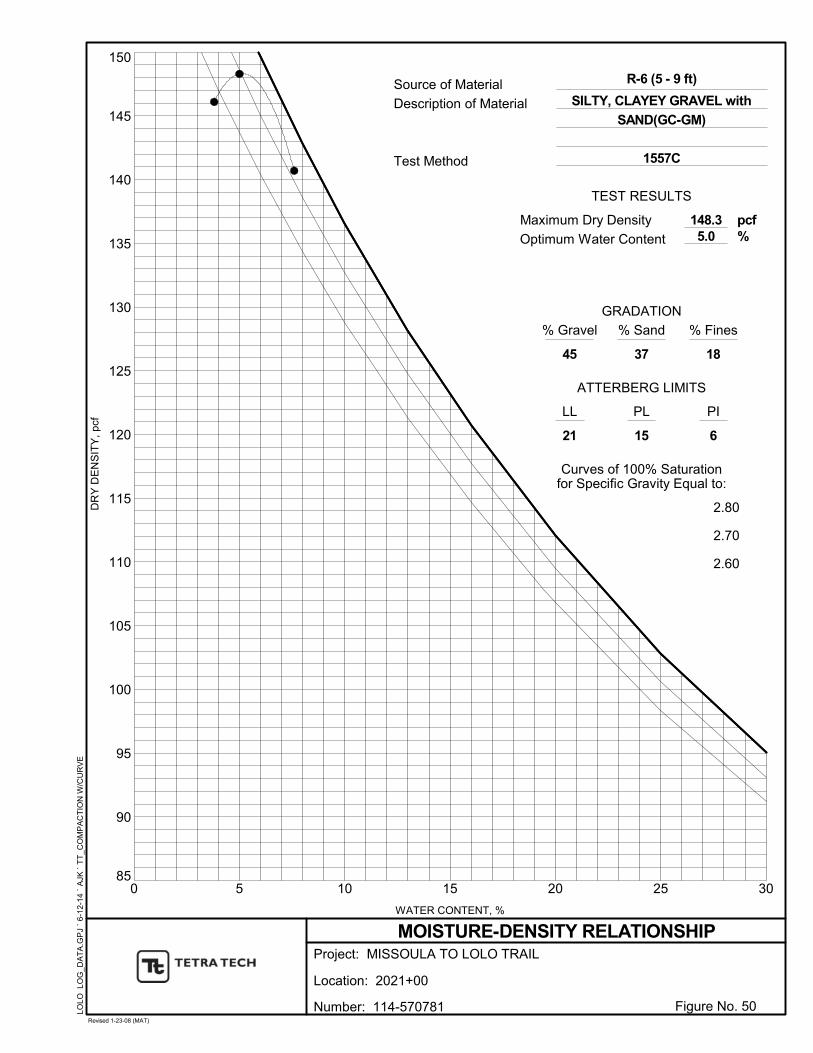
85
90
95
100
105
110
115
120
125
130
135
140
145
150
0 5 10 15 20 25 30
LL
GRADATION
21 6
PL
15
Curves of 100% Saturationfor Specific Gravity Equal to:
2.80
2.70
2.60
PI
Optimum Water Content
Test Method 1557C
148.35.0
% Gravel
37
ATTERBERG LIMITS
45
% Sand % Fines
18
WATER CONTENT, %
Source of Material
Description of MaterialD
RY
DE
NS
ITY
, pc
f
pcf%
TEST RESULTS
LOLO
LO
G_D
AT
A.G
PJ
` 6-
12-
14
` A
JK `
TT
_C
OM
PA
CT
ION
W/C
UR
VE
R-6 (5 - 9 ft)
Project:
Location:
MOISTURE-DENSITY RELATIONSHIP
2021+00
Figure No. 50Revised 1-23-08 (MAT)
MISSOULA TO LOLO TRAIL
SILTY, CLAYEY GRAVEL with
SAND(GC-GM)
Number: 114-570781
Maximum Dry Density
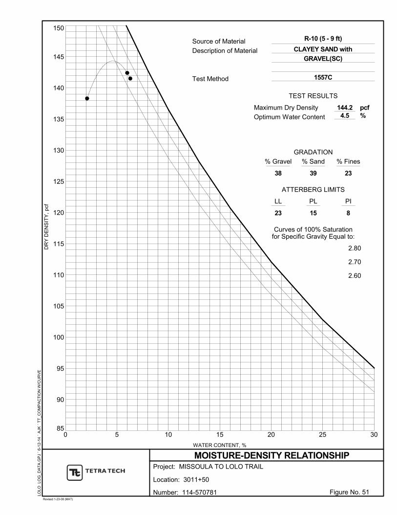
85
90
95
100
105
110
115
120
125
130
135
140
145
150
0 5 10 15 20 25 30
LL
GRADATION
23 8
PL
15
Curves of 100% Saturationfor Specific Gravity Equal to:
2.80
2.70
2.60
PI
Optimum Water Content
Test Method 1557C
144.24.5
% Gravel
39
ATTERBERG LIMITS
38
% Sand % Fines
23
WATER CONTENT, %
Source of Material
Description of MaterialD
RY
DE
NS
ITY
, pc
f
pcf%
TEST RESULTS
LOLO
LO
G_D
AT
A.G
PJ
` 6-
12-
14
` A
JK `
TT
_C
OM
PA
CT
ION
W/C
UR
VE
R-10 (5 - 9 ft)
Project:
Location:
MOISTURE-DENSITY RELATIONSHIP
3011+50
Figure No. 51Revised 1-23-08 (MAT)
MISSOULA TO LOLO TRAIL
CLAYEY SAND with
GRAVEL(SC)
Number: 114-570781
Maximum Dry Density

85
90
95
100
105
110
115
120
125
130
135
140
145
150
0 5 10 15 20 25 30
LL
GRADATION
22 9
PL
13
Curves of 100% Saturationfor Specific Gravity Equal to:
2.80
2.70
2.60
PI
Optimum Water Content
Test Method 1557A
135.68.0
% Gravel
44
ATTERBERG LIMITS
15
% Sand % Fines
41
WATER CONTENT, %
Source of Material
Description of MaterialD
RY
DE
NS
ITY
, pc
f
pcf%
TEST RESULTS
LOLO
LO
G_D
AT
A.G
PJ
` 6-
12-
14
` A
JK `
TT
_C
OM
PA
CT
ION
W/C
UR
VE
R-16 (10 - 18 ft)
Project:
Location:
MOISTURE-DENSITY RELATIONSHIP
3023+50
Figure No. 52Revised 1-23-08 (MAT)
MISSOULA TO LOLO TRAIL
CLAYEY SAND with
GRAVEL(SC)
Number: 114-570781
Maximum Dry Density

85
90
95
100
105
110
115
120
125
130
135
140
145
150
0 5 10 15 20 25 30
LL
GRADATION
24 10
PL
14
Curves of 100% Saturationfor Specific Gravity Equal to:
2.80
2.70
2.60
PI
Optimum Water Content
Test Method 1557C
145.34.3
% Gravel
45
ATTERBERG LIMITS
30
% Sand % Fines
25
WATER CONTENT, %
Source of Material
Description of MaterialD
RY
DE
NS
ITY
, pc
f
pcf%
TEST RESULTS
LOLO
LO
G_D
AT
A.G
PJ
` 6-
12-
14
` A
JK `
TT
_C
OM
PA
CT
ION
W/C
UR
VE
R-20 (5 - 10 ft)
Project:
Location:
MOISTURE-DENSITY RELATIONSHIP
3040+50
Figure No. 53Revised 1-23-08 (MAT)
MISSOULA TO LOLO TRAIL
CLAYEY SAND with
GRAVEL(SC)
Number: 114-570781
Maximum Dry Density
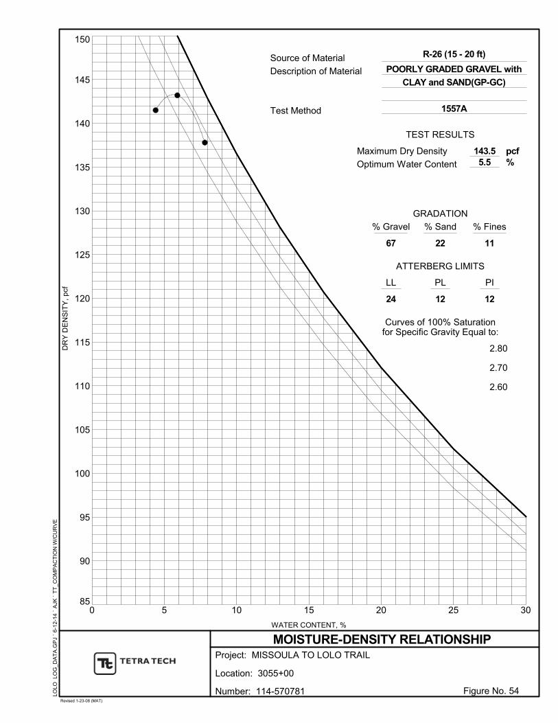
85
90
95
100
105
110
115
120
125
130
135
140
145
150
0 5 10 15 20 25 30
LL
GRADATION
24 12
PL
12
Curves of 100% Saturationfor Specific Gravity Equal to:
2.80
2.70
2.60
PI
Optimum Water Content
Test Method 1557A
143.55.5
% Gravel
22
ATTERBERG LIMITS
67
% Sand % Fines
11
WATER CONTENT, %
Source of Material
Description of MaterialD
RY
DE
NS
ITY
, pc
f
pcf%
TEST RESULTS
LOLO
LO
G_D
AT
A.G
PJ
` 6-
12-
14
` A
JK `
TT
_C
OM
PA
CT
ION
W/C
UR
VE
R-26 (15 - 20 ft)
Project:
Location:
MOISTURE-DENSITY RELATIONSHIP
3055+00
Figure No. 54Revised 1-23-08 (MAT)
MISSOULA TO LOLO TRAIL
POORLY GRADED GRAVEL with
CLAY and SAND(GP-GC)
Number: 114-570781
Maximum Dry Density
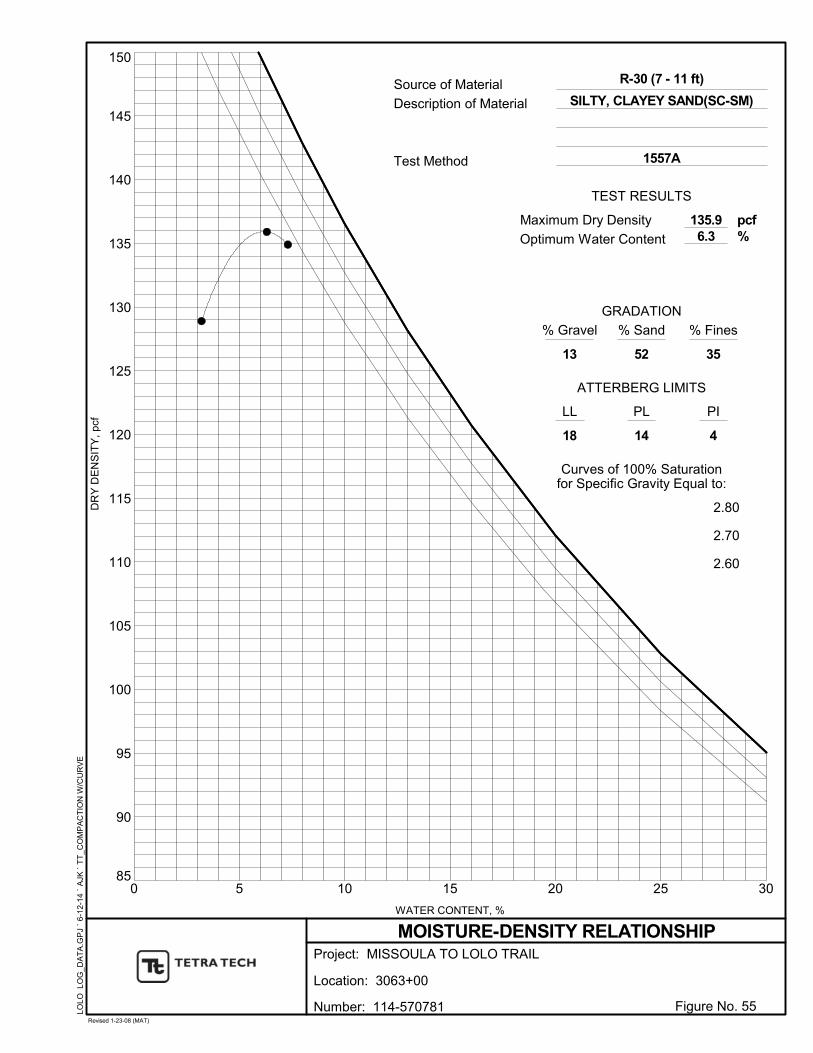
85
90
95
100
105
110
115
120
125
130
135
140
145
150
0 5 10 15 20 25 30
LL
GRADATION
18 4
PL
14
Curves of 100% Saturationfor Specific Gravity Equal to:
2.80
2.70
2.60
PI
Optimum Water Content
Test Method 1557A
135.96.3
% Gravel
52
ATTERBERG LIMITS
13
% Sand % Fines
35
WATER CONTENT, %
Source of Material
Description of MaterialD
RY
DE
NS
ITY
, pc
f
pcf%
TEST RESULTS
LOLO
LO
G_D
AT
A.G
PJ
` 6-
12-
14
` A
JK `
TT
_C
OM
PA
CT
ION
W/C
UR
VE
R-30 (7 - 11 ft)
Project:
Location:
MOISTURE-DENSITY RELATIONSHIP
3063+00
Figure No. 55Revised 1-23-08 (MAT)
MISSOULA TO LOLO TRAIL
SILTY, CLAYEY SAND(SC-SM)
Number: 114-570781
Maximum Dry Density

APPENDIX C
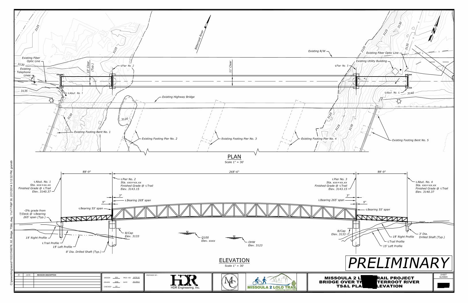
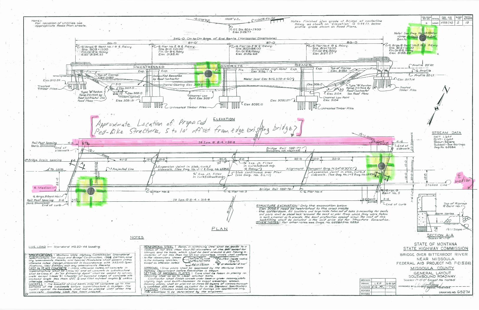
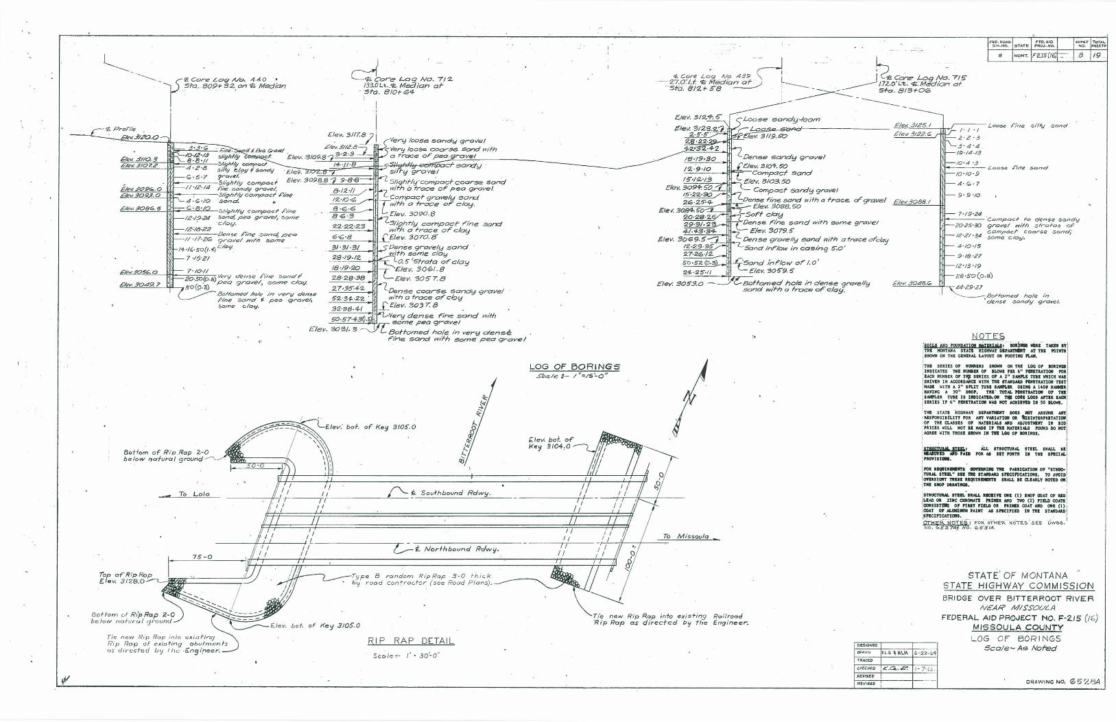
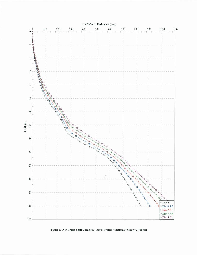
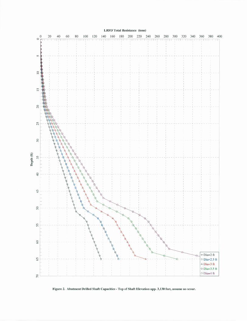
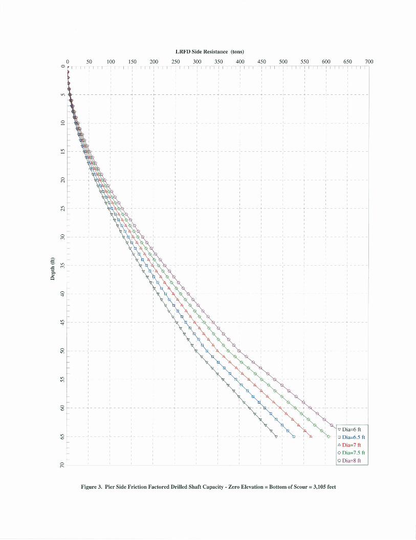
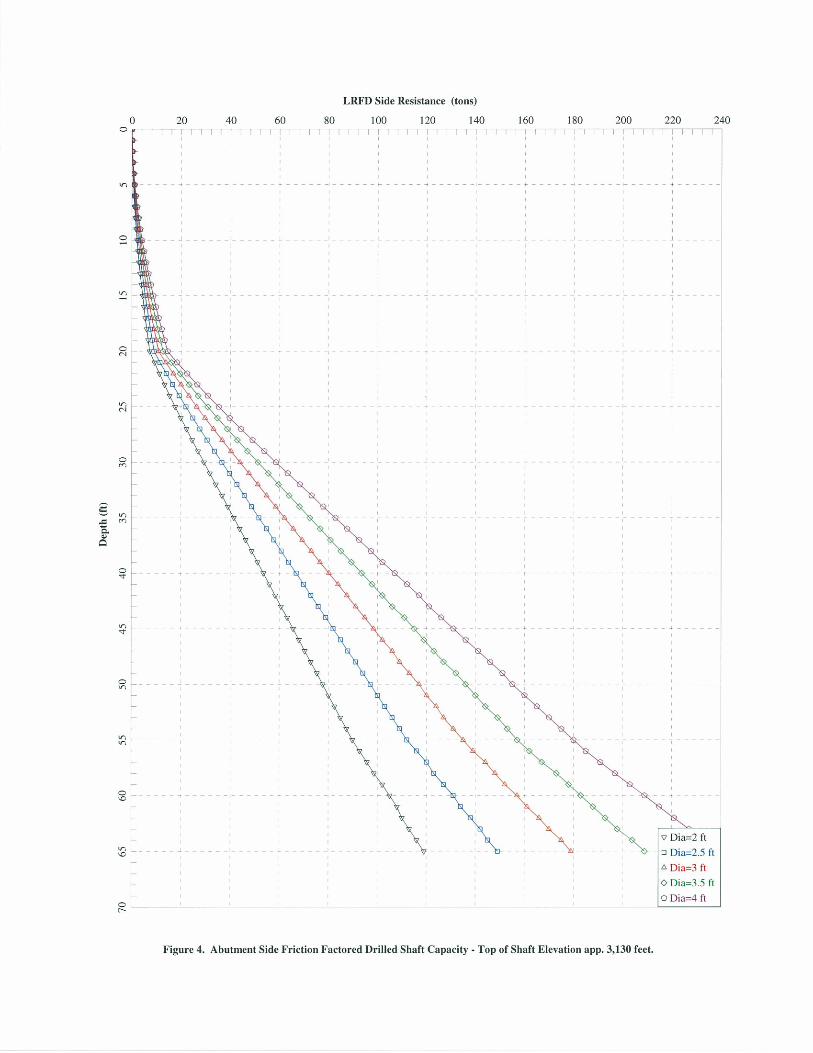

APPENDIX D
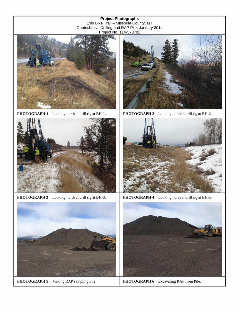
Project Photographs Lolo Bike Trail – Missoula County, MT
Geotechnical Drilling and RAP Pile, January 2014 Project No. 114-570781
PHOTOGRAPH 1 Looking north at drill rig at BH-1. PHOTOGRAPH 2 Looking north at drill rig at BH-2.
PHOTOGRAPH 3 Looking north at drill rig at BH-3. PHOTOGRAPH 4 Looking north at drill rig at BH-5.
PHOTOGRAPH 5 Making RAP sampling Pile. PHOTOGRAPH 6 Excavating RAP from Pile.
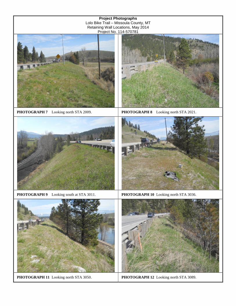
Project Photographs Lolo Bike Trail – Missoula County, MT Retaining Wall Locations, May 2014
Project No. 114-570781
PHOTOGRAPH 7 Looking north STA 2009. PHOTOGRAPH 8 Looking north STA 2021.
PHOTOGRAPH 9 Looking south at STA 3011. PHOTOGRAPH 10 Looking north STA 3036.
PHOTOGRAPH 11 Looking north STA 3050. PHOTOGRAPH 12 Looking north STA 3089.
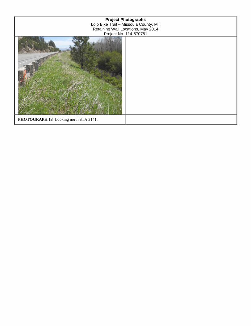
Project Photographs Lolo Bike Trail – Missoula County, MT Retaining Wall Locations, May 2014
Project No. 114-570781
PHOTOGRAPH 13 Looking north STA 3141.

APPENDIX E
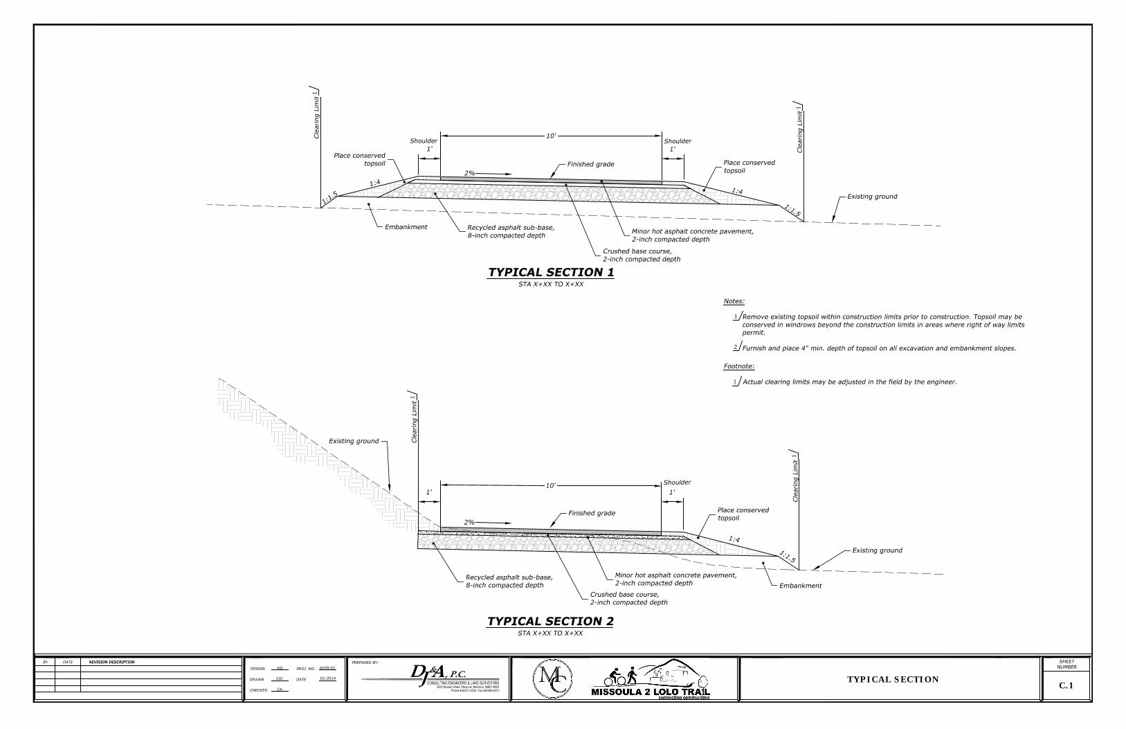
1
1
1
1
1
2
1
C.1
TYPICAL SECTION
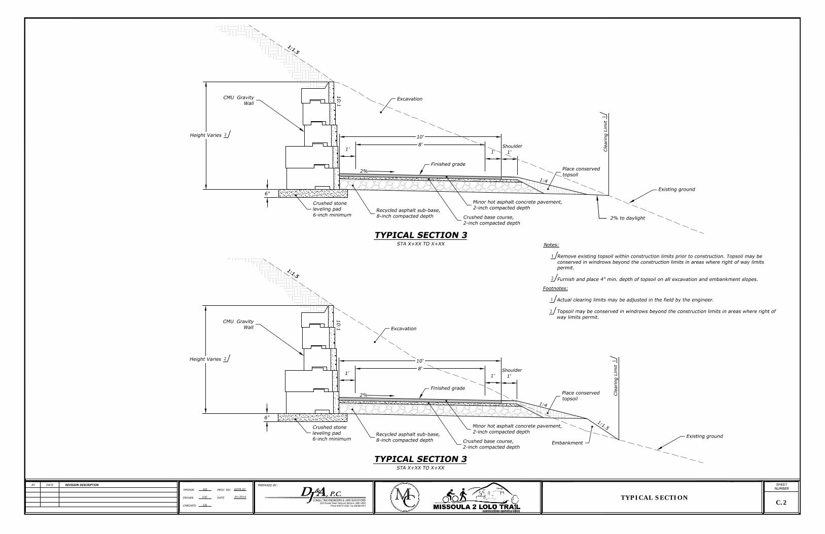
1
2
1
2
1
2
1
2
C.2
TYPICAL SECTION
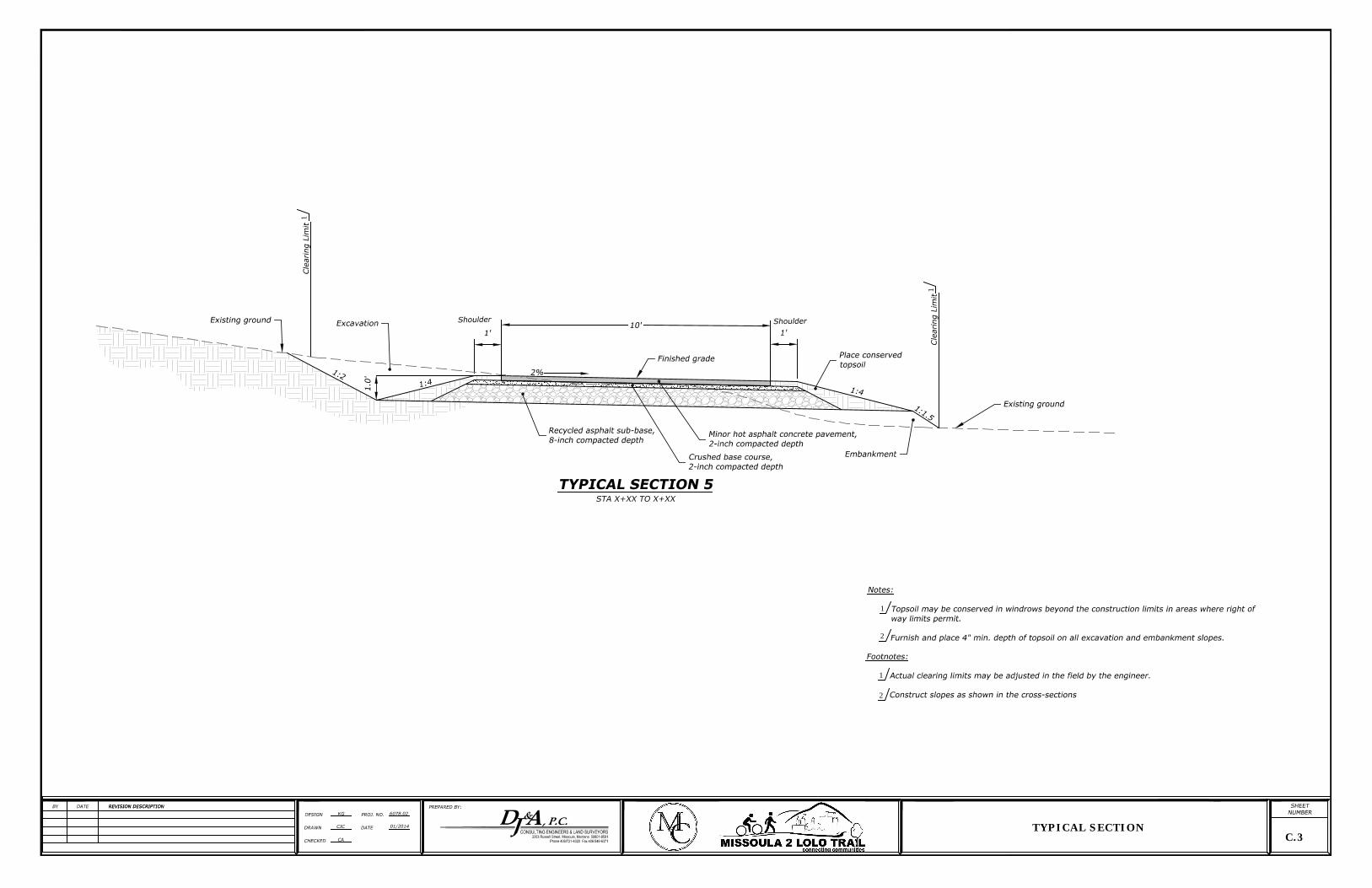
1
1
1
2
C.3
TYPICAL SECTION
1
2

APPENDIX F
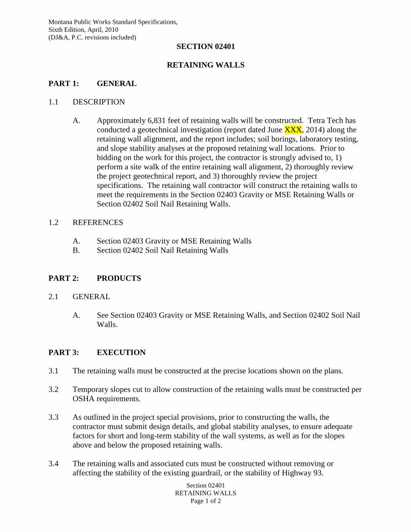
Montana Public Works Standard Specifications,
Sixth Edition, April, 2010
(DJ&A, P.C. revisions included)
Section 02401
RETAINING WALLS
Page 1 of 2
SECTION 02401
RETAINING WALLS
PART 1: GENERAL
1.1 DESCRIPTION
A. Approximately 6,831 feet of retaining walls will be constructed. Tetra Tech has
conducted a geotechnical investigation (report dated June XXX, 2014) along the
retaining wall alignment, and the report includes; soil borings, laboratory testing,
and slope stability analyses at the proposed retaining wall locations. Prior to
bidding on the work for this project, the contractor is strongly advised to, 1)
perform a site walk of the entire retaining wall alignment, 2) thoroughly review
the project geotechnical report, and 3) thoroughly review the project
specifications. The retaining wall contractor will construct the retaining walls to
meet the requirements in the Section 02403 Gravity or MSE Retaining Walls or
Section 02402 Soil Nail Retaining Walls.
1.2 REFERENCES
A. Section 02403 Gravity or MSE Retaining Walls
B. Section 02402 Soil Nail Retaining Walls
PART 2: PRODUCTS
2.1 GENERAL
A. See Section 02403 Gravity or MSE Retaining Walls, and Section 02402 Soil Nail
Walls.
PART 3: EXECUTION
3.1 The retaining walls must be constructed at the precise locations shown on the plans.
3.2 Temporary slopes cut to allow construction of the retaining walls must be constructed per
OSHA requirements.
3.3 As outlined in the project special provisions, prior to constructing the walls, the
contractor must submit design details, and global stability analyses, to ensure adequate
factors for short and long-term stability of the wall systems, as well as for the slopes
above and below the proposed retaining walls.
3.4 The retaining walls and associated cuts must be constructed without removing or
affecting the stability of the existing guardrail, or the stability of Highway 93.
Montana Public Works Standard Specifications,
Sixth Edition, April, 2010
(DJ&A, P.C. revisions included)
Section 02401
RETAINING WALLS
Page 2 of 2
3.5 The contractor may choose to utilize Highway 93 for staging purposes, provided that
traffic control is secured, and that a traffic control plan is submitted to MDT for approval
prior to commencing construction.
3.6 The retaining wall contractor must select equipment, and payloads of delivery and
material trucks, to ensure stability of the embankment slopes during construction. The
Project Manager may elect to limit the size of delivery trucks and loads delivered to the
site based on an evaluation by the Tetra Tech geotechnical engineer during construction.
3.7 The contractor may choose to construct the wall system of their choice at all locations,
provided the walls meet the requirements of the project special provisions, and contains
the facing requirements detailed in the special provisions.
PART 4: MEASUREMENT AND PAYMENT
4.1 Measurement and Payment for Retaining walls will be as outlined in Section 02402 and
Section 02403 as applicable.
END OF SECTION
Montana Public Works Standard Specifications,
Sixth Edition, April, 2010
(DJ&A, P.C. revisions included)
Section 02402
SOIL NAIL RETAINING WALLS
Page 1 of 14
SECTION 02402
SOIL NAIL RETAINING WALLS
PART 1: GENERAL
1.1 DESCRIPTION
A. This work consists of furnishing all materials, labor, and equipment necessary to
design, construct, and test drilled and grouted soil nail retaining walls with
shotcrete facing in accordance with these specifications and the lines, grades, and
dimensions shown on the plans or otherwise established by the Project Manager.
Soil nails must be drilled and grouted. Soil nail construction techniques consisting
of driven soil nails or jet-grouted nails are not acceptable. Have a Professional
Engineer registered in the State of Montana oversee the soil nail retaining wall
design and sign and seal the design calculations and drawings
1.2 REFERENCES
A. Division I, Section 5, Retaining Walls and other appropriate articles of the 17th
Edition of the AASHTO Standard Specification for Highway Bridges (2002)
including current interim specifications.
B. FHWA publication No. FHWA-SA-96-069R, Manual for Design and
Construction Monitoring of Soil Nail Walls, revised Oct. 1998.
C. FWHA publication No. FHWA-IF-03-017, Geotechnical Engineering Circular
No. 7, 2003.
PART 2: PRODUCTS
2.1 GENERAL
A. All materials and products utilized in the construction of the soil nail walls shall
be in conformance with the references listed above, and as further detailed below.
2.2 SOIL NAILS
A. Nail Solid Bar. AAHSTO M31/ASTM A615, Grade 420 or 520, ASTM A 722
for Grade 1035. Deformed bar, continuous without splices or welds, new,
straight, undamaged, bare, or epoxy-coated, or encapsulated as shown on the
Plans. Threaded, a minimum of 6 inches on the wall anchorage end, to allow
proper attachment of bearing plate and nut. Threading may be continuous spiral
deformed ribbing provided by the bar deformations (continuous thread bards) or
may be cut into a reinforcing bar. If threads are cut into a reinforcing bar, provide
the next-larger bar number designation from that is shown on the Plans, at no
additional cost.
Montana Public Works Standard Specifications,
Sixth Edition, April, 2010
(DJ&A, P.C. revisions included)
Section 02402
SOIL NAIL RETAINING WALLS
Page 2 of 14
B. Bar Coupler. Bar couplers shall develop the full ultimate tensile strength of the
bar as certified by the manufacturer.
C. Fusion Bonded Epoxy Coating. ASTM A 775. Minimum 0.016 inch thickness
electrostatically applied. Bend test requirements are waived. Coating at the wall
anchorage end of epoxy-coated bars may be omitted over the length provided for
threading the nut against the bearing plate.
D. Encapsulation. Minimum 0.04-inch thick, corrugated, HDPE tube conforming to
AASHTO M252 or corrugated PVC tube conforming to ASTM D1784, class
13464-B.
2.3 SOIL NAIL APPURTENANCES
A. Centralizer. Manufactured from Schedule 40 PVC pipe or tube, steel, or other
material not detrimental to the nail steel (wood shall not be used); securely
attached to the nail bar; sized to position the nail bar within 1 inch of the center of
the drillhole; sized to allow tremie pipe insertion to the bottom of the drillhole;
and sized to allow grout to freely flow up the drillhole.
B. Nail Grout. Neat cement or sand/cement mixture with a minimum 3-day
compressive strength of 1,500 psi and a minimum 28-day compressive strength of
3,000 psi, per AASHTO T106/ASTM C109.
C. Fine Aggregate. AASHTO M6/ASTM C33
D. Portland Cement. AASHTO M85/ASTM C150, Type I, II, III, or V.
E. Admixtures. AASHTO M194/ASTM C494. Admixtures that control bleed,
improve flowability, reduce water content, and retard set may be used in the grout
subject to review and acceptance by the Engineer. Accelerators are not permitted.
Expansive admixtures may only be used in grout used for filling sealed
encapsulations. Admixtures shall be compatible with the grout and mixed in
accordance with the manufacturer’s recommendations.
F. Film Protection. Polyethylene film per AASHTO M171.
2.4 BEARING PLATES, NUTS, AND WELDED STUD SHEAR CONNECTORS
A. Bearing Plates. AASHTO M183/ASTM A36.
B. Nuts. AASHTO M291, Grade B, hexagonal, fitted with beveled washer or
spherical seat to provide uniform bearing.
C. Shear Connectors. AASHTO Construction Specifications, Section 11.3.3.1.
Montana Public Works Standard Specifications,
Sixth Edition, April, 2010
(DJ&A, P.C. revisions included)
Section 02402
SOIL NAIL RETAINING WALLS
Page 3 of 14
2.5 WELDED WIRE FABRIC
A. Conform to AASHTO M55/ASTM A185 or A497
2.6 REINFORCING STEEL.
A. Conform to AASHTO M31/ASTM A615, Grade 420, deformed.
2.7 GEOCOMPOSITE SHEET DRAIN
A. Manufactured with a drainage core and a drainage geotextile attached to or
encapsulating the core. Drainage core to be manufactured from long-chain
synthetic polymers composed of at least 85 percent by mass of polypropylenes,
polyester, polyamine, polyvinyl choloride, polyoleofin, or polystyrene and having
a minimum compressive strength of 40 psi when tested in accordance with ASTM
D 1621 Procedure A. The drainage core with the geotextile fully encapsulating
the core shall have a minimum flow rate of 1 lieter per second per meter of width
tested in accordance with ASTM D 4716. The test conditions shall be under an
applied load of 10 psi at a gradient of 1.0 after a 100-hour seating period.
2.8 UNDERDRAIN AND PERFORATED PIPE
A. Pipe. ASTM 1785 Schedule 40 PVC solid and perforated wall, cell classification
12454-B or 12354-C, wall thickness SDR 35, with solvent weld or elastomeric
joints.
B. Fittings. ASTM D3034, cell classification 12454-B or C, wall thickness SDR 35,
with solvent or elastomeric joints.
2.9 TEMPORARY SHOTCRETE.
A. Submit for approval, all materials, methods, and control procedures for this work.
PART 3: EXECUTION
3.1 CONTRACTOR EXPERIENCE
A. The wall Contractor must have successfully completed a minimum of three
permanent walls of similar complexity within the last four years, totaling a
minimum face area of 2000 square yards and 500 permanent soil nails. At the
Pre-Construction Conference, submit a package to the Project Manager with a
brief description of each project. The submittal must contain the approximate
face area, number of permanent nails and average length, facing type, owner’s
name, and owner’s current contact information.
3.2 WALL DESIGNER / ENGINEER EXPERIENCE
Montana Public Works Standard Specifications,
Sixth Edition, April, 2010
(DJ&A, P.C. revisions included)
Section 02402
SOIL NAIL RETAINING WALLS
Page 4 of 14
A. The wall Designer/Engineer must have successfully designed and overseen a
minimum of three permanent walls of similar complexity within the last four
years. At the Pre-Construction Conference, submit a package to the Project
Manager with a brief description of each project. The submittal must contain the
approximate face area, number of permanent nails and average length, facing
type, owner’s name, and owner’s current phone number.
3.3 PRECONSTRUCTION CONFERENCE
A. The wall Contractor and the wall Designer/Engineer must attend, or send a duly
appointed representative, to the Pre-Construction Conference.
3.4 DESIGN
A. Meet the following requirements for the design of the soil nail wall(s).
Preliminary wall dimensions given on the plans are for estimating purposes only.
The contractor, through its chosen system, is responsible for producing a design,
which will establish:
a. Soil nail reinforcement type, locations, inclinations, lengths, and strengths.
b. Nail reinforcement connections to permanent facing.
c. Type and dimensions of permanent facing.
d. Grouting procedures and specifications.
e. Design pullout resistance.
f. Minimum boring size for nails.
g. Ultimate anchor capacity.
h. Corrosion protection (75 year design life).
i. Construction sequencing for nail installation and soil excavation.
3.5 AVAILABLE INFORMATION
A. Available information developed by the Owner or by the Owner’s duly authorized
representative includes the following items:
a. Roadway plans. The Roadway plans include the final plans, profile, and
cross-sections for the Contract, including the proposed soil nail wall
locations.
b. Geotechnical Report, prepared by Tetra Tech, dated June xxx, 2014. This
report contains logs of all soil borings performed along the length of the
proposed soil nail wall. It is the responsibility of the contractor to obtain
any additional soil information required to complete the wall design.
c. The design peak ground acceleration is: 0.10g
d. The final design wall batter is 1H:10V
e. Ensure that the soil nail wall design meets the following minimum internal
factors of safety:
Soil Nail Pullout Resistance ≥ 2.0
Montana Public Works Standard Specifications,
Sixth Edition, April, 2010
(DJ&A, P.C. revisions included)
Section 02402
SOIL NAIL RETAINING WALLS
Page 5 of 14
Nail Bar Tensile Strength ≥ 1.8
f. Ensure that the facing strength of the wall design meets the following
minimum factors of safety:
Facing Flexure ≥ 1.5
Facing Punching Shear ≥ 1.5
g. MDT’s Project Geotechnical Consultant evaluated the proposed wall
layout and determined that adequate external factors of safety exist for
global stability and bearing capacity. Verify that the final nail wall design
meets the following minimum external factors of safety (FS):
Global Stability ≥ 1.5
Compound Stability ≥ 1.5
Sliding ≥ 1.5
Seismic Stability FS ≥ 75% of static FS
(all failure modes)
h. Design the wall with a maximum 5-foot vertical and horizontal spacing
between soil nails. The soil nails must be spaced horizontally to penetrate
between the vertical guardrail posts along Interstate 90.
i. All steel components in the wall design must meet FHWA Buy America
requirements.
Design a drainage system to drain water and prevent hydrostatic pressure
buildup behind the facing. Include details in the drainage system for a
permanent interception ditch to control surface runoff and direct runoff
away from the top of the wall as shown in the Plans. The permanent ditch
must be constructed of reinforced concrete, a minimum of 2 feet in width,
4 inches in thickness, and graded to drain horizontally away from the top
of the wall. The permanent ditch must have outlets spaced at a maximum
of 250 feet to drain surface runoff to the drainage system and away from
the wall area.
j. Aesthetic Treatment. Apply an Aesthetic Treatment to the wall facing
consisting of a permanent stain applied by the Contractor.
1. Obtain prior approval from the Project Manager for the aesthetic
treatment. The method(s) for demonstrating the quality and color
of the aesthetic treatment are the sole responsibility of the
Contractor. Do not begin the aesthetic treatment without written
approval from the Project Manager.
2. Stain the facing to approximate and blend with the color(s) of
adjacent cut sections.
3. Apply the permanent stain in accordance with the manufacturer’s
recommendations.
4. If the unstained color of the shotcrete facing generally matches the
color of the new adjacent cuts prior to staining, the Project
Manager may waive the staining requirement at their discretion.
k. The shotcrete mixture must contain provisions for fiber reinforcement to
increase the durability of the mix and resistance to crack propagation. If
steel fibers are used, the design must incorporate measures to prevent
rusting of the fibers and discoloration of the final wall face.

Montana Public Works Standard Specifications,
Sixth Edition, April, 2010
(DJ&A, P.C. revisions included)
Section 02402
SOIL NAIL RETAINING WALLS
Page 6 of 14
3.6 SOIL NAIL WALL DESIGN REQUIREMENTS.
A. Ensure that the wall has an adequate factor of safety with respect to both the
internal stability of the reinforced soil mass (including nail pullout and nail bar
tensile strength), and the external stability (including global stability, bearing
capacity, and sliding) in the wall design. The design life of the structure is 75
years unless otherwise specified. Design the wall in accordance with Division I,
Section 5, Retaining Walls and other appropriate articles of the 17th
Edition of the
AASHTO Standard Specification for Highway Bridges (2002) including current
interim specifications. Design the wall using the Load Resistance Factor Design
(LRFD) approach in accordance with FHWA publication No. FHWA-SA-96-
069R, Manual for Design and Construction Monitoring of Soil Nail Walls,
revised Oct. 1998 and general guidance from the FWHA publication No. FHWA-
IF-03-017, Geotechnical Engineering Circular No. 7, 2003.
3.7 SOIL NAIL WALL DESIGN SUBMITTALS
A. At least 30 calendar days before the planned start of wall excavation, submit
complete design calculations and working drawings to DJ and A for review and
comment. Include all details, dimensions, quantities, ground profiles, and cross-
sections necessary to construct the wall. Verify the limits of the wall and ground
survey data before preparing drawings.
3.8 DESIGN CALCULATIONS
A. Design calculations must include, but not be limited to, the following items:
a. A written summary report that describes the overall soil nail wall design.
b. Applicable code requirements and design references.
c. Soil nail wall critical design cross-sections geometry including soil strata
and location, magnitude, and direction of design slope or external
surcharge loads and piezometric levels.
d. Design criteria including, soil/rock shear strengths (friction angle and
cohesion), unit weights, bond strength between the in situ soils and grout,
and any other assumptions for each soil strata.
e. Factors of safety used for internal stability checks, surcharges, soil unit
weights, reinforcing material properties, and wall panel unit materials.
Minimum required global factors of safety for stability and sliding for
both construction, and long-term conditions.
f. Design calculation sheets with:
Project Name
Wall Designer/Engineer’s project number
Wall location
Designation
Date of preparation
Initials of designer and checker
Page number at the top of each page.
Montana Public Works Standard Specifications,
Sixth Edition, April, 2010
(DJ&A, P.C. revisions included)
Section 02402
SOIL NAIL RETAINING WALLS
Page 7 of 14
An index page with the design calculations.
g. Design notes including an explanation of any symbols and computer
programs used in the design.
h. Soil nail wall final design cross-sections geometry including soil/rock
strata and location, magnitude, and direction of slope or external surcharge
loads and piezometric levels with critical slip surface shown along with
minimum calculated global stability and sliding factors of safety for both
construction, and long term conditions.
i. Structural design calculations for the shotcrete wall facing, connections,
soil nails, and connections between the soil nails and the facing.
j. Grout mix compressive strength test results, from a qualified independent
testing laboratory, verifying that the proposed nail grout mix will achieve
the specified 3-day (72 hour) compressive strength.
k. Other design calculations.
3.9 WORKING DRAWINGS
A. Working drawings must include, but are not limited to, the following items:
a. A plan view of the wall(s) identifying:
b. A reference baseline and elevation datum.
c. The offset from the construction centerline or baseline to the face of the
wall at its base at all changes in horizontal alignment.
d. Beginning and end of wall stations.
e. Right-of-way and permanent or temporary construction easement limits,
location of all known active and abandoned existing utilities, adjacent
structures or other potential interferences, the centerline of any drainage
structure or drainage pipe behind, passing through, adjacent to, or passing
under the wall.
f. Limits of longest nails.
g. Location of subsurface exploration borings performed by Tetra Tech.
h. An elevation view of the wall(s) identifying:
a. The elevation at the top of the wall, at all horizontal and vertical break
points, and at least every 15 feet along the wall.
j. Elevations at the wall base.
k. Beginning and end of wall stations.
l. The distance along the face of the wall to all steps in the wall base.
m. Wall elevation view showing the location of wall drainage elements along
the wall length.
n. Existing and finish grade profiles both behind and in front of the wall.
o. Design parameters and applicable codes.
p. Specifications for soil nails and connection pins.
q. General notes for constructing the wall including construction sequencing,
wall excavation, foundation preparation, wall erection, grouting
procedures and other special construction requirements.
r. Horizontal and vertical curve data affecting the wall and wall control
points.

Montana Public Works Standard Specifications,
Sixth Edition, April, 2010
(DJ&A, P.C. revisions included)
Section 02402
SOIL NAIL RETAINING WALLS
Page 8 of 14
s. Match lines or other details to relate wall stationing to centerline
stationing.
t. A listing of the summary of quantities on the elevation drawing of each
wall showing estimated square feet of wall face areas.
u. Soil nail wall typical sections including excavation elevations, nail
inclination, and wall face batter.
v. Details and dimensions for wall appurtenances such as barriers, coping,
drainage gutters, guardrail installations, sign posts, fences, etc.
w. Details for constructing walls around drainage facilities (if applicable).
x. Details for terminating walls and adjacent slope construction.
y. Details for performing verification and proof testing of the nails.
B. Have a Registered Professional Engineer sign and seal the drawings and
calculations. If the soil nail wall Contractor uses a Consultant designer
subcontractor or manufacturer’s representative to prepare the design, the soil nail
wall Contractor still retains overall contractual responsibility for both the design
and the construction.
C. Submit 3 sets of the wall drawings with the initial submission. One set will be
returned with any indicated corrections. DJ and A will review and provide
comments on the Contractor's submittals within 15 calendar days after receipt of a
complete submission. If revisions are necessary, make the necessary corrections
and resubmit 3 revised sets. When the drawings are approved, furnish 5 sets of
the drawings and a digital copy of the drawings in “PDF” format to the Project
Manager. The Contractor will not be allowed to begin wall construction or
incorporate materials into the work until the submittal requirements are satisfied
and found acceptable to the Owner. Changes or deviations from the approved
submittals must be re-submitted for approval. No adjustments in contract time
will be allowed due to incomplete submittals.
D. Revise the drawings when plan dimensions are revised due to field conditions or
for other reasons. Within 30 days after completion of the work, submit as-built
drawings to the Project Manager. Provide revised design calculations signed by a
Registered Professional Engineer for all design changes made during the
construction of the wall.
E. Provide 5 sets of the drawings and a digital copy of the drawings showing the
final as-built wall, design revisions, and revised calculations in “PDF” format to
the Project Manager.
3.10 MATERIALS AND CONSTRUCTON REQUIREMENTS
A. Construct the wall and perform verification and proof testing according to the
approved set of working drawings and in accordance with the wall designer’s and
wall manufacturer’s recommendations, the Special Provisions, and the appropriate
sections of the Specifications.
Montana Public Works Standard Specifications,
Sixth Edition, April, 2010
(DJ&A, P.C. revisions included)
Section 02402
SOIL NAIL RETAINING WALLS
Page 9 of 14
3.11 NAIL TESTING CRITERIA
A. Test nails using the following criteria:
a. Perform both verification and proof testing of designated test nails.
b. Perform Verification Tests on sacrificial test nails at locations shown on
the Plans or directed by the Project Manager.
c. Proof test production nails at locations selected by the Project Manager.
The Project Manager will observe and verify the nail testing performed by
the Contractor.
d. Do not perform Verification or Proof testing until the nail grout has cured
for at least 72 hours.
e. Provide temporary unbonded lengths for each test nail. Isolate the test nail
bar from the shotcrete facing and/or the reaction frame used during testing.
Isolation of a test nail through the shotcrete facing must not affect the
location of the reinforcing steel under the bearing plate. Accepted proof
test nails may be incorporated as production nails provided the temporary
test unbonded length is fully grouted subsequent to testing. Submit the
proposed test nail isolation methods, methods for providing an unbonded
test length and methods for grouting the unbonded length subsequent to
testing to the Project Manager for review and approval in accordance with
the Submittals section. Where temporary casing of the unbonded length of
test nails is provided, install the casing in a manner that prevents any
reaction between the casing and the grouted bond length of the nail and/or
the stressing apparatus.
f. Include dial gauges, dial gauge support, jack and pressure gauge,
electronic load cell, and a reaction frame in the testing equipment. The
load cell is required only for the creep test portion of the verification test.
Provide a description of test setup and jack, pressure gauge and load cell
calibration curves in accordance with Submittals section.
g. Design the testing reaction frame to be sufficiently rigid and of adequate
dimensions so that excessive deformation of the testing equipment does
not occur. If the reaction frame will bear directly on the shotcrete facing,
design it to prevent cracking of the shotcrete. Independently support and
center the jack over the nail bar so that the bar does not carry the weight of
the testing equipment. Align the jack, bearing plates, and stressing
anchorage with the bar such that unloading and repositioning of the
equipment will not be required during the test.
h. Apply and measure the test load with a hydraulic jack and pressure gauge.
Provide a pressure gauge graduated in 100 psi (689 kPa) increments or
less. Provide a jack and pressure gauge with a pressure range not
exceeding twice the anticipated maximum test pressure. Jack ram travel
must be sufficient to allow the test to be done without resetting the
equipment. Monitor the nail load during Pre-Production Verification tests
with both the pressure gauge and the load cell. Use the load cell to
maintain a constant load hold during the creep test load hold increment of
the verification test.
Montana Public Works Standard Specifications,
Sixth Edition, April, 2010
(DJ&A, P.C. revisions included)
Section 02402
SOIL NAIL RETAINING WALLS
Page 10 of 14
i. Measure the nail head movement with a dial gauge capable of measuring
to 0.01 inches (0.25 mm). Provide a dial gauge with sufficient travel to
allow the test to be done without having to reset the gauge. Visually align
the gauge to be parallel with the axis of the nail and support the gauge
independently from the jack, wall, or reaction frame. Use two dial gauges
when the test setup requires reaction against a soil cut face.
j. Perform verification testing of sacrificial nails a minimum of two working
days prior to installation of production nails to verify the Contractor's
installation methods and nail pullout resistance. Perform verification tests
at the locations and elevations shown on the Plans or as directed by the
Project Manager. Test a minimum of 2 times in each different soil/rock
unit and for each different proposed drilling/grouting method.
Verification test nails are considered sacrificial and cannot be incorporated
as production nails. Bare bars may be used for the sacrificial verification
test nails.
k. Develop and submit the details of the verification testing arrangement,
including the method of distributing test load pressures to the excavation
surface (reaction frame), test nail bar size, grouted drillhole diameter, and
reaction frame dimensioning to the Project Manager for approval in
accordance with Submittals section.
l. Construct verification test nails using the same equipment, installation
methods, nail inclination, and drillhole diameter as planned for the
production nails. Changes in the drilling or installation method may
require additional verification testing as determined by the Project
Manager and must be provided at no additional cost to the Department.
m. Provide test nails with both bonded and temporary unbonded lengths.
Grout only the bonded length of the test nail prior to testing. Provide a
temporary unbonded length of the test nail of at least 3 feet (1 meter).
Determine the bonded length of the test nail based on the production nail
bar grade and size such that the allowable bar structural load is not
exceeded during testing, but not less than 10 feet (3 meters). Ensure the
allowable bar structural load during testing is not greater than 90 percent
of the yield strength for the specified bar Grade.
n. Determine the Design Test Load (DTL) during verification testing by the
following equation:
DTL = Design Test Load (kips or kN) = LBV x Qd
Where:
LBV = As-built bonded test length (ft or m)
Qd = Allowable pullout resistance (kips/ft or kN/m, of
grouted nail length, specified in the approved
submittals)
And:
Maximum Test Load (MTL) = 2.0 x DTL (kips or kN)
Montana Public Works Standard Specifications,
Sixth Edition, April, 2010
(DJ&A, P.C. revisions included)
Section 02402
SOIL NAIL RETAINING WALLS
Page 11 of 14
o. Incrementally load the verification test nails to a Maximum Test Load of
200% of the Design Test Load (DTL) in accordance with the following
Loading Schedule. Record the soil nail movements at each load
increment. Develop a form to record test nail location, inclination,
azimuth, bond length, test start-finish time, incremental loading dial
records and measurements of creep during the Creep Test.
VERIFICATION TEST LOADING SCHEDULE
LOAD HOLD TIME
AL (0.05 DTL maximum) 1 minute
0.25 DTL 10 minutes
0.50 DTL 10 minutes
0.75 DTL 10 minutes
1.00 DTL 10 minutes
1.25 DTL 10 minutes
1.50 DTL (Creep Test) 60 minutes
1.75 DTL 10 minutes
2.00 DTL (Maximum Test Load) 10 minutes
The Alignment Load (AL) should be the minimum load required to
align the testing apparatus and should not exceed 5% of the Design
Test Load (DTL). Set dial gauges to "zero" after the alignment
load has been applied. Monitor the verification test nails for the
creep test at the 1.50 DTL increment. Measure the nail movements
during the creep test and record at 1, 2, 3, 5, 6, 10, 20, 30, 50, and
60 minutes. Maintain the load during the creep test within 2% of
the intended load by use of the load cell.
p. Perform proof testing on 10% (1 in 10) of the production nails in each nail
row or minimum of 1 per row. The Project Manager will designate the
testing locations.
q. Provide proof test nails with both bonded and temporary unbonded
lengths. Prior to testing, grout only the bonded length of the test nail.
Provide a temporary unbonded length of the test nail of at least 3 feet (1
meter). Determine the bonded length of the test nail based on the
production nail bar grade and size such that the allowable bar structural
load is not exceeded during testing, but not less than 10 feet (3 meters).
Proof test nails shorter than 12 feet (4 meters) in length may be
constructed with less than the minimum 10 foot (3 meters) bond length
with the unbonded length limited to 3 feet (1 meter). Ensure the allowable
bar structural load during testing is not greater than 90% of the yield
strength for the specified bar Grade.
r. Determine the Design Test Load (DTL) during proof testing by the
following equation:
DTL = Design Test Load (kips or kN) = LBP x Qd
Where:
LBP = As-built bonded test length (feet or meters)
Montana Public Works Standard Specifications,
Sixth Edition, April, 2010
(DJ&A, P.C. revisions included)
Section 02402
SOIL NAIL RETAINING WALLS
Page 12 of 14
Qd = Allowable pullout resistance (kips/ft or kN/m, of
grouted nail length, specified in the approved
submittals)
And:
Maximum Test Load (MTL) = 2.0 x DTL (kips or kN)
s. Perform proof tests by incrementally loading to a Maximum Test Load of
150% of the Design Test Load (DTL) in accordance with the following
Loading Schedule. Measure and record the nail movement at each load
with the Project Manager observing and verifying the data in the same
manner as the verification tests. Monitor the proof test load using a jack
pressure gauge with a sensitivity and range meeting the requirements of
pressure gauges used for verification test nails. At load increments other
than the Maximum Test Load, hold the load long enough to obtain a stable
reading.
PROOF TEST LOADING SCHEDULE
LOAD HOLD TIME
AL (0.05 DTL maximum) Until Stable
0.25 DTL Until Stable
0.50 DTL Until Stable
0.75 DTL Until Stable
1.00 DTL Until Stable
1.25 DTL Until Stable
1.50 DTL (Maximum Test Load) See Below
The Alignment Load (AL) should be the minimum load required to align
the testing apparatus and should not exceed 5% of the Design Test Load
(DTL). Set dial gauges to "zero" after the Alignment Load has been
applied. Maintain load increments within 5% of the intended load.
Depending on performance, perform either 10 minute or 60 minute creep
tests at the Maximum Test Load (1.50 DTL). Start the creep period as
soon as the Maximum Test Load is applied and measure and record the
nail movement at 1, 2, 3, 5, 6, and 10 minutes. Where the nail movement
between 1 minute and 10 minutes exceeds 0.04 inches (1mm), maintain
the Maximum Test Load an additional 50 minutes and record movements
at 20, 30, 50, and 60 minutes.
3.12 TEST NAIL ACCEPTANCE CRITERIA
A. Consider test nail acceptable when:
a. For verification tests, a total creep movement of less than 0.01 inches
(0.25 mm) per log cycle of time between the 6 and 60 minute readings is
measured during creep testing and the creep rate is linear or decreasing
throughout the creep test load hold period.
b. For proof tests, a total creep movement of less than 0.04 inches (1 mm) is
measured between the 1 and 10 minute readings or a total creep movement
of less than 0.08 inches (2 mm) is measured between the 6 and 60 minute

Montana Public Works Standard Specifications,
Sixth Edition, April, 2010
(DJ&A, P.C. revisions included)
Section 02402
SOIL NAIL RETAINING WALLS
Page 13 of 14
readings and the creep rate is linear or decreasing throughout the creep test
load hold period.
c. For verification and proof tests, the total measured movement at the
maximum test load exceeds 80% of the theoretical elastic elongation of
the test nail unbonded length.
d. A pullout failure does not occur at the applicable Maximum Test Load for
the test being performed (i.e. verification vs. proof testing). Pullout failure
is defined as the load at which attempts to further increase the test load
simply result in continued pullout movement of the test nail. Record the
pullout failure load as part of the test data.
e. Incorporate successful proof tested nails meeting the above test acceptance
criteria as production nails, provided that:
f. The unbonded length of the test nail drillhole has not collapsed during
testing.
g. The minimum required drillhole diameter has been maintained.
h. The specified corrosion protection is provided.
i. The test nail length is equal to or greater than the scheduled Production
Nail length.
j. Complete the installation of test nails meeting these requirements by
satisfactorily grouting the unbonded test length. Maintaining the
temporary unbonded test length for subsequent grouting is the Contractor's
responsibility. If the unbonded test length of production proof test nails
cannot be satisfactorily grouted subsequent to testing, the proof test nail is
sacrificial and must be replaced with an additional production nail
installed at no additional cost to the Department.
3.13 Test Nail Rejection Criteria.
A. If a test nail does not satisfy the acceptance criterion, determine the cause.
B. For verification test nails, the Project Manager will evaluate the results of each
verification test. Installation methods which do not satisfy the nail testing
requirements will be rejected. The Contractor must propose alternative
installation methods and install replacement verification test nails. Install and test
replacement test nails at no additional cost to the Department.
C. For proof test nails, the Project Manager may require the Contractor to replace
some or all of the installed production nails between a failed proof test nail and
the adjacent passing proof test tail.
D. Alternatively, the Project Manager may require the installation and testing of
additional proof test nails to verify that adjacent previously installed production
nails have sufficient load carrying capacity. Contractor modifications may
include, but are not limited to: the installation of additional proof test nails;
increasing the drillhole diameter to provide increased capacity; modifying the
installation or grouting methods; reducing the production nail spacing from that
specified in the approved submittals; and installing more production nails at a
reduced capacity.
Montana Public Works Standard Specifications,
Sixth Edition, April, 2010
(DJ&A, P.C. revisions included)
Section 02402
SOIL NAIL RETAINING WALLS
Page 14 of 14
E. Installation and testing of additional proof test nails or installation of additional or
modified nails as a result of proof test nail failure(s) will be at no additional cost
to the Department.
3.14 RECORDS
A. Submit records of each soil nail installation on a daily basis and submit a
summary form of all installations performed on a weekly basis to the project
manager.
PART 4: MEASUREMENT AND PAYMENT
4.1 MEASUREMENT
A. SOIL NAIL WALL
1. Soil Nail Retaining Walls will be measured by the finished area of wall
face per square foot. The finished area is calculated based on the height of
wall from the finished grade at the toe of the wall to the top of the wall as
measured in the field, installed, and accepted.
4.2 PAYMENT
A. The accepted quantities will be paid for at the contract unit price per unit of
measurement as reflected in the bid schedule. Payment will be full compensation
for all labor, equipment, materials, tests, investigations, and incidentals necessary
to acceptably design, construct, and test the soil nail retaining walls.
END OF SECTION
Montana Public Works Standard Specifications,
Sixth Edition, April, 2010
(DJ&A, P.C. revisions included)
Section 02403
GRAVITY OR MSE RETAINING WALLS
Page 1 of 8
SECTION 02403
GRAVITY OR MSE RETAINING WALLS
PART 1: GENERAL
1.1 DESCRIPTION
A. Description. Furnish all materials, labor, and equipment necessary to design and
construct Gravity or Mechanically Stabilized Earth (MSE) retaining wall(s) in
accordance with these specifications and the lines, grades, and dimensions shown
on the plans or otherwise established by the Engineer. Have a professional
engineer licensed in Montana oversee the retaining wall design and sign and seal
the design calculations and drawings.
B. Preliminary dimensions given on the plans are for estimating purposes only.
Produce a design for a Gravity or MSE wall system that will establish:
1. Bottom elevation of leveling pad and wall
2. Reinforcement type, locations and lengths if applicable
3. Type and dimensions of facing materials
4. Reinforcement connection to facing
5. Size of concrete and/or crushed aggregate leveling pad.
6. Quantity and specifications of backfill
7. A drainage system that will provide free drainage behind the soil mass.
8. A design that takes into account interferences such as guardrail posts, and
pipes behind, passing through, or under the wall.
1.2 REFERENCES
FHWA-NHI-10-024 Design and Construction of Mechanically Stabilized
Earth Walls and Reinforced Slopes
FHWA-SA-96-038 Earth Retaining Systems
FHWA-HRT-10-077 Composite Behavior of Geosynthetic Reinforced
Soil Mass
FHWA-NHI-09-087 Corrosion/Degradation of Soil Reinforcements for
Mechanically Stabilized Earth Walls and
Reinforced Slopes
FHWA-RD-89-186 Durability/Corrosion of Soil Reinforced Structures
AASHTO 2013 LRFD Specifications for Highway Bridges
PART 2: PRODUCTS
2.1 Use materials meeting the following requirements to construct Gravity or MSE walls.
Montana Public Works Standard Specifications,
Sixth Edition, April, 2010
(DJ&A, P.C. revisions included)
Section 02403
GRAVITY OR MSE RETAINING WALLS
Page 2 of 8
1. Concrete for Leveling Pads. Provide MDT Class DD or equivalent Concrete for
leveling pads. The bottom of the concrete leveling pad shall be provided with a
minimum soil cover of 42 inches for frost protection.
2. Backfill Material. Use material meeting the following requirements:
a. Gradation for backfill:
US Sieve Size Percent Passing
3 inch 100
1 inch 70 - 90
No. 4 20 – 40
No. 40 10 – 20
No. 200 0 – 8
Provide a minimum of 35% of the +No. 4 material with at least one
mechanically fractured face.
b. Electrochemical Properties. For MSE walls, use backfill meeting the
following electrochemical requirements:
For Steel Reinforcements:
Requirements Test Methods
Resistivity >3,000 ohm-cm AASHTO T-288
pH 5-10 AASHTO T-289
Chlorides <100 parts per million AASHTO T-291
Sulfates <200 parts per million AASHTO T-290
Organic Content <1% AASHTO T-267
For Geosynthetic Reinforcements:
Requirements Test Methods
Polyester (PET) 3<pH<9 AASHTO T-289
Polyolefin (PP &HDPE) pH>3 AASHTO T-289
If the resistivity of the sites soils is greater than or equal to 5000
ohm-cm, the chloride and sulfates requirements may be waived.
c. Soundness. Use materials that are substantially free of shale or other soft,
poor durability particles. Use material having a magnesium sulfate
soundness loss of less than 30 percent after four cycles, measured in
accordance with AASHTO T-104, or a sodium sulfate less of less than 15
percent after five cycles determined in accordance with AASHTO T-104.
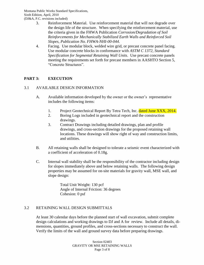
Montana Public Works Standard Specifications,
Sixth Edition, April, 2010
(DJ&A, P.C. revisions included)
Section 02403
GRAVITY OR MSE RETAINING WALLS
Page 3 of 8
3. Reinforcement Material. Use reinforcement material that will not degrade over
the design life of the structure. When specifying the reinforcement material, use
the criteria given in the FHWA Publication Corrosion/Degradation of Soil
Reinforcements for Mechanically Stabilized Earth Walls and Reinforced Soil
Slopes, Publication No. FHWA-NHI-00-044.
4. Facing. Use modular block, welded wire grid, or precast concrete panel facing.
Use modular concrete blocks in conformance with ASTM C 1372, Standard
Specification for Segmental Retaining Wall Units. Use precast concrete panels
meeting the requirements set forth for precast members in AASHTO Section 5,
“Concrete Structures”.
PART 3: EXECUTION
3.1 AVAILABLE DESIGN INFORMATION
A. Available information developed by the owner or the owner’s representative
includes the following items:
1. Project Geotechnical Report By Tetra Tech, Inc. dated June XXX, 2014.
2. Boring Logs included in geotechnical report and the construction
drawings.
3. Contract Drawings including detailed drawings, plan and profile
drawings, and cross-section drawings for the proposed retaining wall
locations. These drawings will show right of way and construction limits,
and utilities.
B. All retaining walls shall be designed to tolerate a seismic event characterized with
a coefficient of acceleration of 0.18g.
C. Internal wall stability shall be the responsibility of the contractor including design
for slopes immediately above and below retaining walls. The following design
properties may be assumed for on-site materials for gravity wall, MSE wall, and
slope design:
Total Unit Weight: 130 pcf
Angle of Internal Friction: 36 degrees
Cohesion: 0 psf
3.2 RETAINING WALL DESIGN SUBMITTALS
At least 30 calendar days before the planned start of wall excavation, submit complete
design calculations and working drawings to DJ and A for review. Include all details, di-
mensions, quantities, ground profiles, and cross-sections necessary to construct the wall.
Verify the limits of the wall and ground survey data before preparing drawings.

Montana Public Works Standard Specifications,
Sixth Edition, April, 2010
(DJ&A, P.C. revisions included)
Section 02403
GRAVITY OR MSE RETAINING WALLS
Page 4 of 8
A. Design Calculations. Submit design calculations to include, but not be limited to,
the following items:
1. Applicable code requirements and design references.
2. Retaining wall critical design cross-section geometry including soil/rock
strata and location, magnitude, and direction of design slope or external
surcharge loads and piezometric levels along with the Capacity Demand
Ratios for, long-term conditions.
3. Design parameters including drained and undrained soil/rock shear
strengths (friction angle and cohesion), unit weights, and any other
assumptions for each soil/rock strata along with reinforcing material
properties, and facing materials.
4. Capacity Demand Ratios calculated from LRFD.
5. Design calculation sheets with the project number, wall location,
stationing, date of preparation, initials of designer and checker, and page
number at the top of each page. Provide an index page with the design
calculations.
6. Design notes including an explanation of any symbols and computer
programs used in the design.
7. Design calculations for wall facing units, connection pins, and reinforcing
material, and connections between the reinforcing material and the facing.
8. Other design calculations.
B. Working Drawings. Provide drawings designed, signed and sealed by a registered
Professional Engineer licensed in the State of Montana. Working drawings shall
include, but not be limited to, the following items:
1. A plan view of the wall(s) identifying:
a. A reference baseline and elevation datum.
b. The offset from the construction centerline or baseline to the face
of the wall at its base at all changes in horizontal alignment.
c. Beginning and end of wall stations.
d. Right-of-way and permanent or temporary construction easement
limits, location of all known active and abandoned existing
utilities, adjacent structures or other potential interferences within
the limits of the wall excavation. The centerline of any drainage
structure or drainage pipe behind, passing through, or passing
under the wall.
2. An elevation view of the wall(s) identifying:
a. The elevation at the top of the wall, at all horizontal and vertical
break points, and at least every 20 feet along the wall.
b. Elevations at the wall base.
c. Beginning and end of wall stations.
d. The distance along the face of the wall to all steps in the wall base.
e. Wall elevation view showing the location of wall drainage
elements along the wall length.
f. Existing and finish grade profiles both behind and in front of the
wall.

Montana Public Works Standard Specifications,
Sixth Edition, April, 2010
(DJ&A, P.C. revisions included)
Section 02403
GRAVITY OR MSE RETAINING WALLS
Page 5 of 8
3. Specifications for reinforcing material and connection pins.
4. General notes for constructing the wall including construction sequencing,
wall excavation, foundation preparation, wall erection, backfill placement
and any other special construction requirements.
5. Horizontal and vertical curve data affecting the wall and wall control
points. Match lines or other details to relate wall stationing to centerline
stationing.
6. A listing of the summary of quantities on the elevation drawing of each
wall showing estimated square meters of wall face areas.
7. Retaining wall typical sections including excavation elevations, and wall
face batter.
8. Details, dimensions, and schedules for all connection pins, facing, and
reinforcement materials.
9. Details and dimensions for wall appurtenances such as barriers, guardrails,
coping, drainage gutters, fences, signage, etc.
10. Details for constructing walls around utilities and drainage facilities (if
applicable).
11. Details for terminating walls and adjacent slope construction.
12. Clearly show all details and requirements to place guardrail posts.
Have a Professional Engineer licensed in Montana sign and seal the
drawings and calculations. If the retaining wall Contractor uses a
Consultant designer subcontractor or manufacturer’s representative to
prepare the design, the retaining wall Contractor still has overall contract
responsibility for both the design and the construction.
Submit 3 sets of the wall drawings to DJ and A with the initial submission. DJ
and A will review the Contractor's submittals within 20 calendar days after receipt
of a complete submission. If revisions are necessary, make the necessary
corrections and resubmit 3 revised sets. After the drawings have been reviewed
and found acceptable, furnish 5 sets of the drawings. Do not begin wall
construction or incorporate materials into the work until the submittal
requirements are satisfied and found acceptable to DJ and A. Changes or
deviations from the accepted submittals must be re-submitted and reviewed. No
adjustments in contract time will be allowed due to incomplete submittals.
Revise the drawings when plan dimensions are revised due to field conditions or
for other reasons. Within 30 days after completion of the work, submit as-built
drawings to the Engineer. Provide revised design calculations signed by a
Registered Professional Engineer for all design changes made during the
construction of the wall.
3.3 CONSTRUCTION
A. Construct the wall according to the approved set of working drawings, the special
provisions, and the appropriate sections of the Standard Specifications.
Montana Public Works Standard Specifications,
Sixth Edition, April, 2010
(DJ&A, P.C. revisions included)
Section 02403
GRAVITY OR MSE RETAINING WALLS
Page 6 of 8
1. Reinforced Backfill Source Approval. At least 30 calendar days before
beginning wall construction, submit a sample from the proposed borrow
source for backfill material.
2. Reinforcement Source Approval. Submit a manufacturer’s certificate of
compliance signed by an authorized manufacturer’s official stating that the
reinforcement material meets the requirements specified in the working
drawings. Submit a sample at least 5 feet in length by the full
reinforcement width for testing. After the sample and the required
information have been submitted to the Project Manager, allow 30
calendar days for evaluation. Remove and replace any material not
meeting the specified requirements at the Contractor’s expense.
3. Have a technical representative of the wall manufacturer on site during the
beginning of wall construction to ensure that the wall is installed properly.
4. Excavation. Complete the excavation in reasonably close conformity to
the limits shown on the approved design plans. The contractor is
responsible for temporary excavation support (as required).
5. Foundation Preparation. Prior to wall construction, compact the
foundation soils to a minimum of 95 percent of ASTM D698. The surface
should be smooth and level such that any shallow depressions or humps do
not exceed 6 inches in depth or height. Proofroll the subgrade and remove
and replace any unsuitable foundation soils with backfill material as per
Materials of these specifications. Do not use vibratory compaction
equipment unless approved by the Project Manager.
6. After placement of the leveling pad concrete, allow it to cure a minimum
of 12 hours before placing wall panels or modular block units.
7. Backfill Placement. Place backfill following each course of facing. Place
and compact backfill in such a manner to avoid any disturbance of the
wall materials or misalignment of the facing or reinforcing element.
Remove and replace any wall materials that become damaged during
construction at Contractor’s expense. Place, spread, and compact backfill
in such a manner that minimizes development of wrinkles in or movement
of reinforcement. Place backfill near the facing to assure that no voids
exist directly beneath the reinforcing elements. Place backfill in
maximum 8 inch loose lifts. Compact backfill to a minimum of 95 percent
of the maximum density determined by ASTM D698 within +/- 2 percent
of the optimum moisture content. Compact the backfill within 4 feet of
the wall face using a lightweight mechanical tamper or roller. Do not use
vibratory compaction equipment unless approved by the Project Manager..
At the end of each day’s operation, slope the level of the backfill away
from the wall facing to rapidly direct runoff away from the face. Do not
allow surface water from adjacent areas to enter the wall construction site.
8. Reinforcement Placement. At each reinforcement level, place and
compact the backfill to the level of the reinforcement. Place
reinforcement on a smooth horizontal surface. Pull the reinforcement
material tight before covering it with backfill. If using a geosynthetic
reinforcement, orientation of geosynthetic reinforcement is critical since
the strength of geosynthetic reinforcement varies with direction. Use soil
Montana Public Works Standard Specifications,
Sixth Edition, April, 2010
(DJ&A, P.C. revisions included)
Section 02403
GRAVITY OR MSE RETAINING WALLS
Page 7 of 8
piles, pins, or the manufacturer’s approved method to hold the
reinforcement material tight during backfill placement. Do not operate
equipment directly on the reinforcement material. Do not splice or
overlap geosynthetic reinforcement in the principal strength direction.
9. Modular Block Fill. Fill the voids in all modular blocks with aggregate
satisfying the following gradation:
US Sieve Size Percent Passing
1 inch 100
¾ inch 50-75
No. 4 0-60
No. 40 0-50
No. 200 0 - 5
10. Wall Batter. The completed wall has a vertical tolerance not exceeding
1/2 inch per 10 feet of wall height from the batter shown on the approved
set of working drawings.
11. Corrective Action. If any defects are found in the wall, begin repairing the
wall by a method approved by DJ and A. Within seven calendar days of
determining the need for wall repairs, submit four copies of calculations
and working drawings, stamped by a Professional Engineer licensed in
Montana, to the Project Manager for modifications to the wall caused by
the remedial action. Furnish all material and labor necessary to correct the
wall at no cost to the Department.
12. Contractor shall submit a construction plan to the Project Manager
approval prior to mobilization of materials or equipment. The
construction plan shall include schedules, excavation plans, excavation
safety, staging areas, surface water management plan.
13. Contractor shall submit an emergency response plan for Project Manager
approval prior to mobilization of materials. The plan shall include
provisions for traffic management in the event of construction excavation
slope failure.
14. Construction shall proceed in accordance with the approved construction
plan based on the type of walls selected.
PART 4: MEASUREMENT AND PAYMENT
4.1 MEASUREMENT
A. GRAVITY OR MSE WALL
1. Gravity or MSE retaining walls will be measured by the finished area of
wall face per square foot. The finished area is calculated based on the
height of wall from the finished grade at the toe of the wall to the top of
the wall as measured in the field, installed, and accepted.
4.2 PAYMENT

Montana Public Works Standard Specifications,
Sixth Edition, April, 2010
(DJ&A, P.C. revisions included)
Section 02403
GRAVITY OR MSE RETAINING WALLS
Page 8 of 8
A. The accepted quantities will be paid for at the contract unit price per unit of
measurement as reflected in the bid schedule. Payment will be full compensation
for all labor, equipment, materials, tests, investigations, and incidentals necessary
to acceptably design, construct, and test the retaining walls.
END OF SECTION

Montana Public Works Standard Specifications,
Sixth Edition, April, 2010
(DJ&A, P.C. revisions included)
Section 02510
ASPHALT CONCRETE PAVEMENT
Page 1 of 21
SECTION 02510
ASPHALT CONCRETE PAVEMENT
PART 1: GENERAL
1.1 DESCRIPTION
A. This work is the production and placement of plant mix asphalt concrete
pavement.
B. Hot plant mix asphalt concrete is a mineral aggregate and asphalt material mixed
at a central hot plant meeting these specifications and placed in one or more
courses on a newly prepared or existing street roadway in accordance with the
contract documents.
1.2 REFERENCES
AASHTO T11 Amount of Material Finer than No. 200 (0.075 mm) Sieve
(ASTM D1140) in Aggregate
ASTM D5361 Standard Practice for Sampling Compacted Bituminous
Mixtures for Laboratory Testing
AASHTO T27 Sieve Analysis of Fine and Coarse Aggregate
(ASTM C136)
AASHTO T89 Determining Liquid Limit of Soils
(ASTM D4318)
AASHTO T90 Determining the Plastic Limit and Plasticity Index of Soils
(ASTM D4318)
AASHTO T283 Resistance of Compacted Asphalt Mixtures to Moisture-
(ASTM D4867) Induced Damage
AASHTO T176 Sand Equivalent Value of Soils and Fine Aggregate
(ASTM D2419)
AASHTO T245 Resistance to Plastic Flow of Bituminous Mixtures Using
(ASTM D6926, D6927) Marshall Apparatus
AASHTO T96 Resistance to Degradation of Small-Size Coarse Aggregate
(ASTM C131) by Abrasion and Impact in the Los Angeles Machine
ASTM D2041 Theoretical Maximum Specific Gravity and Density of
Bituminous Mixtures
ASTM C1097 Hydrated Lime for Use in Asphaltic Concrete Mixtures
ASTM D3666 Evaluating and Qualifying Agencies Testing and
Inspecting
ASTM D5821 Determining the Percentage of Fractured Particles in
Coarse Aggregate
ASTM C123 Lightweight Particles in Aggregate
ASTM D6307 Asphalt Content of Hot Mix Asphalt by Ignition Method
ASTMC142 Clay Lumps and Friable Particles in Aggregates
MS-2 Asphalt Institute - Mix Design Methods
Montana Public Works Standard Specifications,
Fifth Edition, March 2003
(DJ&A, P.C. revisions included)
Section 02510
ASPHALT CONCRETE PAVEMENT
Page 2 of 21
PART 2: PRODUCTS
2.1 GENERAL
A. The specific type and grading of aggregate shall be consistent with those used on
other local, state, or federal projects with similar type construction as is outlined
for this project. Submit proposed aggregate gradation to the Engineer for
approval. Aggregate types and grades are described in this specification.
B. The furnishing of asphalt materials for use in asphaltic concrete mixes shall meet
the requirements for the particular grade specified in the contract documents. The
types and grades are described in this specification.
C. Prepare pavement course to conform to the lines, grades, thickness and typical
cross sections shown in project documents and plans, and shall be rolled, finished,
and approved by the Engineer before the placement of the next course.
2.2 PLANT MIX AGGREGATES
A. Furnish aggregates from acceptable sources approved by the Engineer. Up to 20
percent by weight Recycled Asphalt Pavement (RAP) may be substituted for
Plant Mix Aggregate, provided the RAP meets the gradation requirements
below, and the RAP mix meets the mix design requirements listed below.
B. Furnish test data as outlined in this section on each source to be used for
acceptance by the Engineer.
C. Designation of the sources of supply and the acceptability of the material there
from, does not extend to the grading of the material as it may naturally come from
the pit or crusher. Adjust the crusher and screens to remove certain portions of
the material as may be necessary to furnish gravel that will comply with the
specifications in the contract. No additional compensation will be allowed for
such adjustment of the equipment or the rejection of waste. It is understood that
the Engineer may order procurement of material from any portion of any area
designated as a pit site and may reject portions of the deposit as unacceptable.
D. Aggregate materials shall not contain more than 1.5% by weight of clay lumps,
shale, or coal, nor lightweight particles shall exceed 3.5% by weight. No
combination of clay, shale, coal, or lightweight particles shall exceed 3.5% by
weight. Do not use Scoria (fired clay). Aggregate materials shall conform to the
grading stipulated in the contract documents. Use reasonable care in the selection
of material in a pit so that uniform product will be produced at all times. No
compensation will be allowed for such stripping of the pit as may be required in
order that satisfactory material may be secured.
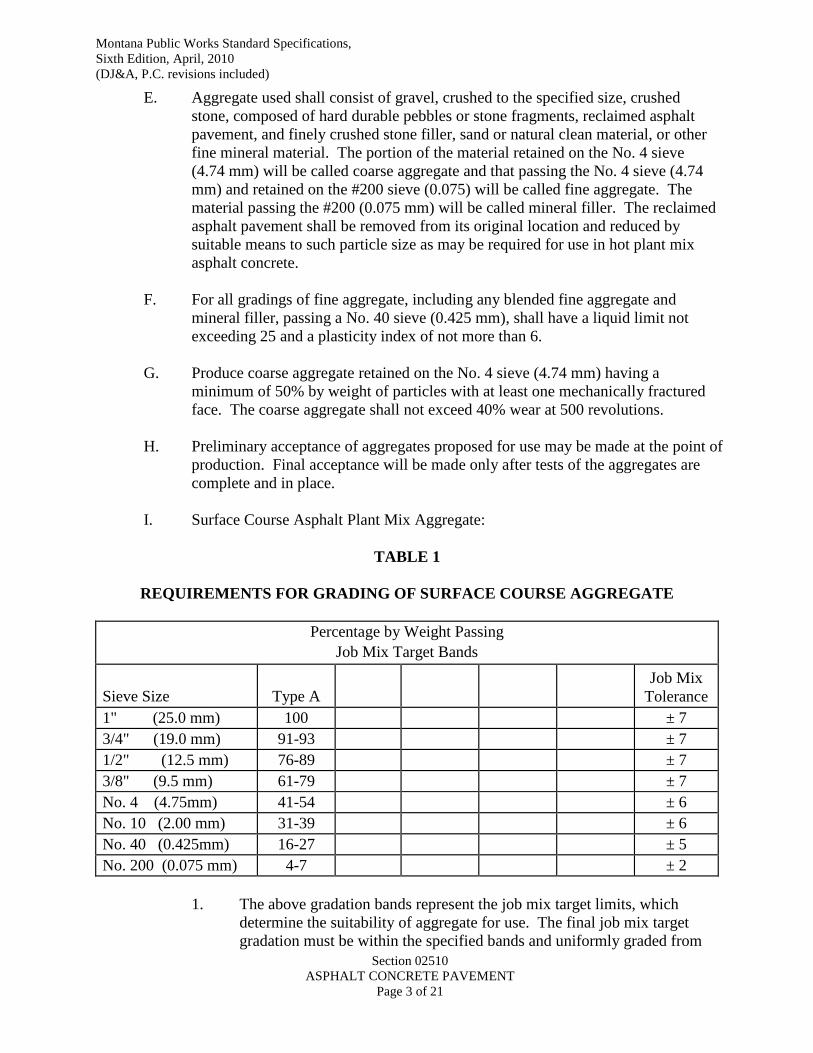
Montana Public Works Standard Specifications,
Sixth Edition, April, 2010
(DJ&A, P.C. revisions included)
Section 02510
ASPHALT CONCRETE PAVEMENT
Page 3 of 21
E. Aggregate used shall consist of gravel, crushed to the specified size, crushed
stone, composed of hard durable pebbles or stone fragments, reclaimed asphalt
pavement, and finely crushed stone filler, sand or natural clean material, or other
fine mineral material. The portion of the material retained on the No. 4 sieve
(4.74 mm) will be called coarse aggregate and that passing the No. 4 sieve (4.74
mm) and retained on the #200 sieve (0.075) will be called fine aggregate. The
material passing the #200 (0.075 mm) will be called mineral filler. The reclaimed
asphalt pavement shall be removed from its original location and reduced by
suitable means to such particle size as may be required for use in hot plant mix
asphalt concrete.
F. For all gradings of fine aggregate, including any blended fine aggregate and
mineral filler, passing a No. 40 sieve (0.425 mm), shall have a liquid limit not
exceeding 25 and a plasticity index of not more than 6.
G. Produce coarse aggregate retained on the No. 4 sieve (4.74 mm) having a
minimum of 50% by weight of particles with at least one mechanically fractured
face. The coarse aggregate shall not exceed 40% wear at 500 revolutions.
H. Preliminary acceptance of aggregates proposed for use may be made at the point of
production. Final acceptance will be made only after tests of the aggregates are
complete and in place.
I. Surface Course Asphalt Plant Mix Aggregate:
TABLE 1
REQUIREMENTS FOR GRADING OF SURFACE COURSE AGGREGATE
Percentage by Weight Passing
Job Mix Target Bands
Sieve Size Type A
Job Mix
Tolerance
1" (25.0 mm) 100 ± 7
3/4" (19.0 mm) 91-93 ± 7
1/2" (12.5 mm) 76-89 ± 7
3/8" (9.5 mm) 61-79 ± 7
No. 4 (4.75mm) 41-54 ± 6
No. 10 (2.00 mm) 31-39 ± 6
No. 40 (0.425mm) 16-27 ± 5
No. 200 (0.075 mm) 4-7 ± 2
1. The above gradation bands represent the job mix target limits, which
determine the suitability of aggregate for use. The final job mix target
gradation must be within the specified bands and uniformly graded from
Montana Public Works Standard Specifications,
Fifth Edition, March 2003
(DJ&A, P.C. revisions included)
Section 02510
ASPHALT CONCRETE PAVEMENT
Page 4 of 21
coarse to fine and not vary from the low limits on one screen to the high
limits on the adjacent screen, or vice versa. The final job mix gradation
limits are established by applying the job mix tolerances to the job mix
targets.
2. The job mix formula establishes target values. During production of the
mix, the target gradation shall lie within the job mix grading limits
specified in Table 1. For example, “Type A, No. 200” band is “4-7”. ZA
job mix target of 5 has been selected for the final mix. The job mix
gradation limits is 5, plus and minus 2. Therefore, the job mix gradation
limits for production is 3-7.
2.3 ASPHALT BINDER MATERIAL
A. Furnish Asphalt binder material to be used as specified in the contract documents
that meet the type and grade specified requirements in this section and Table 3.
1. Grade:
a. (PGAB) PG 58-28
B. The percentage of asphalt by weight, to be added to the aggregate will be,
generally, between 4 and 8 percent of the weight of the total mix. The mix design
will establish the exact percentage of asphalt in the mix, based upon preliminary
laboratory tests, sieve analysis and grading and character of the aggregate
furnished within the specification limits. No claim is allowed for the payment for
rejecting any batch or load of mixture containing an excess or deficient amount of
asphalt binder varying more than 0.4 of a percent from the fixed mix design
percentage.
C. Obtain Engineer approval of the asphalt material source before shipments are
made to any project. The source of supply cannot change after work is started
unless approved in writing by the Engineer. The Engineer is not liable for the
quantity shipped.
D. Samples of asphalt binder material may be taken, as directed by the Engineer, and
placed in uncontaminated one-quart containers. When sampled, these shall be
taken from the tanker car or truck at the point of delivery on the project and
submitted to the Engineer.
E. All transport vehicles must be equipped with a spigot or gate valve installed in
either: (1) the unloading line, (2) in the tanker at the centerline on the tank, (3) in
the pressure line from the unloading pump, or other locations approved by the
Engineer. Assure the spigot or gate valve has a diameter of between 3/8 inch (1
cm) and 3/4 inch (2.5 cm). The spigot valve must be located to prevent
contamination from plant dust or other contaminants.
Montana Public Works Standard Specifications,
Fifth Edition, March 2003
(DJ&A, P.C. revisions included)
Section 02510
ASPHALT CONCRETE PAVEMENT
Page 5 of 21
F. The supplier furnishing the asphalt binder material shall inspect each tanker car or
truck before it is loaded and ship only in clean, uncontaminated, fully insulated
cars or trucks, sealed after loading by the supplier.
G. The material supplier shall issue, in duplicate, a certificate showing full
compliance with the specifications for the designated grade of material, together
with the following information. Project number, date of shipment, source of the
material, car or truck initial and number, destination, gross quantity loaded,
loading temperature, and net quantity in gallons at 60F (15.5 C) or tons,
whichever unit of measurement is stipulated. Assure the certificate of compliance
accompanies the shipment and is furnished to the Engineer. The certificate,
signed by the supplier representative, must also certify that the conveyance vessel
was inspected and found to be free of contaminating material.
H. The certificate of compliance is the basis for tentative acceptance and use of the
material. Samples taken according to applicable sampling methods and retained
by the Engineer may be tested at the Engineer’s discretion. Failure of the asphalt
material to meet these specifications may result in rejection of the entire,
associated work. If rejected, remove and replace rejected work.
I. Apply asphalt material at temperatures that assure uniform mixing or spreading.
Application temperature ranges for each grade of material should be accompanied
with the mix design. Application temperature for mixing applications will be in
accordance with the mix design.
J. Upon request by the Engineer, furnish the Engineer and/or laboratory (responsible
for completing the mix design) with data or a report showing the temperature-
viscosity relationship of each asphalt binder used on the project. Assure this data
covers the range of temperatures used for mixing and compaction. In addition,
the Engineer may request a complete set of test results from Table 3 for each
grade used on the project.
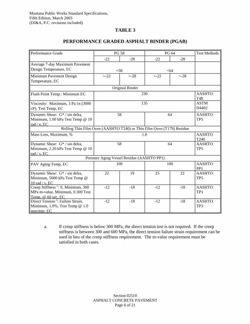
Montana Public Works Standard Specifications,
Fifth Edition, March 2003
(DJ&A, P.C. revisions included)
Section 02510
ASPHALT CONCRETE PAVEMENT
Page 6 of 21
TABLE 3
PERFORMANCE GRADED ASPHALT BINDER (PGAB)
Performance Grade PG 58 PG 64 Test Methods
-22 -28 -22 -28
Average 7-day Maximum Pavement
Design Temperature, C <58 <64
Minimum Pavement Design
Temperature, C
>-22 >-28 >-22 >-28
Original Binder
Flash Point Temp.: Minimum C 230 AASHTO
T48
Viscosity: Maximum, 3 Pa s (3000
cP), Test Temp, C
135 ASTM
D4402
Dynamic Shear: G* / sin delta,
Minimum, 1.00 kPa Test Temp @ 10
rad / s, C
58 64 AASHTO
TP5
Rolling Thin Film Oven (AASHTO T240) or Thin Film Oven (T179) Residue
Mass Loss, Maximum, % 1.0 AASHTO
T240
Dynamic Shear: G* / sin delta,
Minimum, 2.20 kPa Test Temp @ 10
rad / s, C
58 64 AASHTO
TP5
Pressure Aging Vessel Residue (AASHTO PP1)
PAV Aging Temp, C
100 100 AASHTO
PP1
Dynamic Shear: G* / sin delta,
Minimum, 5000 kPa Test Temp @
10 rad / s, C
22 19 25 22 AASHTO
TP5
Creep Stiffness a: S, Minimum, 300
MPa m-value, Minimum, 0.300 Test
Temp, @ 60 sec, C
-12 -18 -12 -18 AASHTO
TP1
Direct Tension a: Failure Strain,
Minimum, 1.0%, Test Temp @ 1.0
mm/min. C
-12 -18 -12 -18 AASHTO
TP3
a. If creep stiffness is below 300 MPa, the direct tension test is not required. If the creep
stiffness is between 300 and 600 MPa, the direct tension failure strain requirement can be
used in lieu of the creep stiffness requirement. The m-value requirement must be
satisfied in both cases.

Montana Public Works Standard Specifications,
Fifth Edition, March 2003
(DJ&A, P.C. revisions included)
Section 02510
ASPHALT CONCRETE PAVEMENT
Page 7 of 21
2.4 COMPOSITION OF MIXES:
A. General
1. Submit to the engineer for approval a mix design for each mix required on
the project. Assure the job-mix formula is within the gradation limits in
Part 2 Products in this Section.
2. Have the job-mix formula prepared by an independent testing laboratory
approved by the Engineer. The requirements of ASTM D-3666 are the
guidelines for testing laboratory approval. The cost of the job-mix
formula(s) is at Contractor expense.
3. Keep the job mix formula current and contain the following minimum
information:
a. Gradation of all constituent aggregates.
b. Specific gravity of constituent aggregates and asphalt cement.
c. Source of supply of all materials and grade of asphalt cement.
d. Marshall design curves for stability, unit weight, flow and
volumetric requirements (VMA and total voids) at asphalt contents
below and above optimum (four points minimum).
e. Measured voidless (Rice’s) specific gravity used in voids
computations.
f. Composite aggregate grading.
g. Recommended asphalt cement content.
h. Marshall compactive effort (50 blows).
i. Date of mix design (job mix formula).
j. Index of retained strength.
4. In addition to the job mix formula, all asphalt concrete surfacing mix
submittals will have laboratory tests indicating that the Tensile Strength
Ratio (TSR) as determined by AASHTO T-283, is at least 70%. Test shall
be performed at 7.0 +/- 1% air voids and shall include the freeze cycle.
B. Asphalt Concrete Surface Course
1. The maximum permissible variation from the job-mix formula within the
specification limits is as follows:
a. Aggregate Gradation……………….. Within Job Mix Tolerances
b. Asphalt …………………………………………± 0.4 percent*
c. Temperature of Mix ……………………………± 20° F
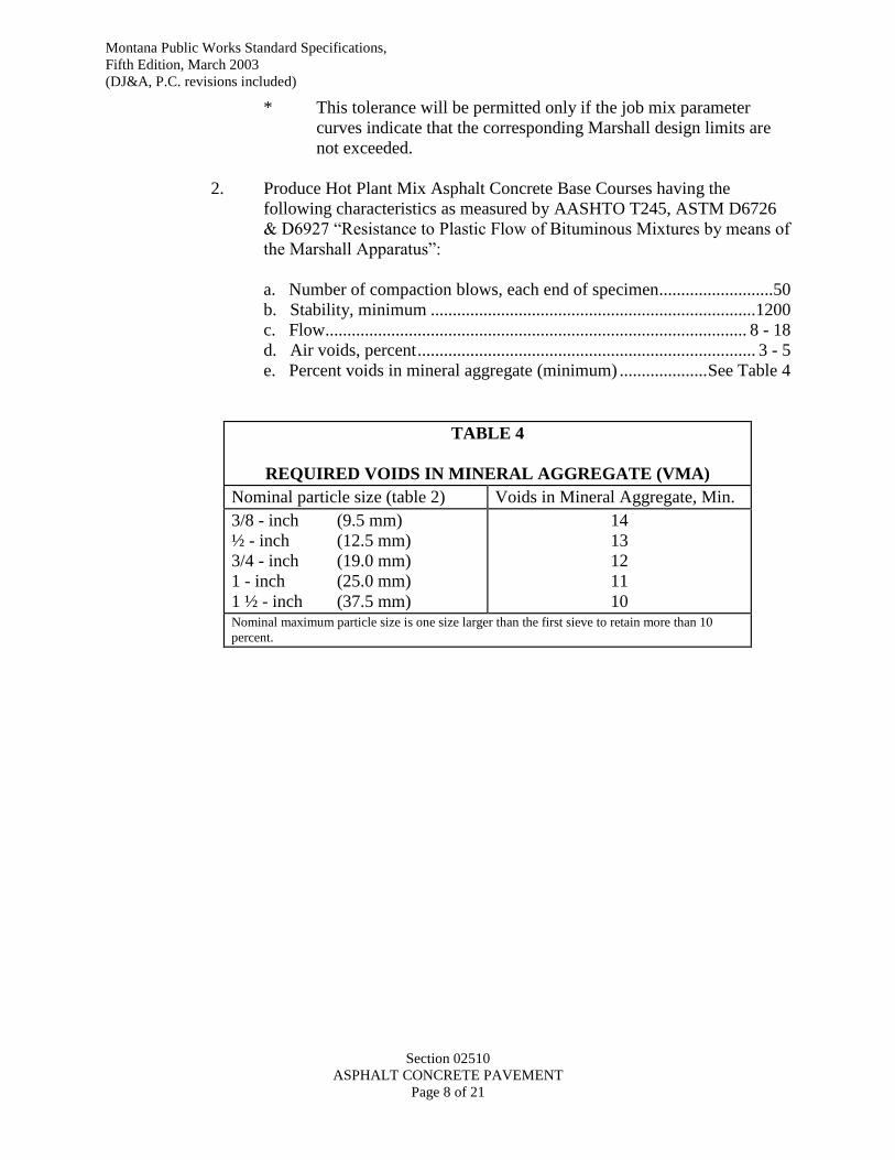
Montana Public Works Standard Specifications,
Fifth Edition, March 2003
(DJ&A, P.C. revisions included)
Section 02510
ASPHALT CONCRETE PAVEMENT
Page 8 of 21
* This tolerance will be permitted only if the job mix parameter
curves indicate that the corresponding Marshall design limits are
not exceeded.
2. Produce Hot Plant Mix Asphalt Concrete Base Courses having the
following characteristics as measured by AASHTO T245, ASTM D6726
& D6927 “Resistance to Plastic Flow of Bituminous Mixtures by means of
the Marshall Apparatus”:
a. Number of compaction blows, each end of specimen ..........................50
b. Stability, minimum ..........................................................................1200
c. Flow................................................................................................ 8 - 18
d. Air voids, percent ............................................................................. 3 - 5
e. Percent voids in mineral aggregate (minimum) .................... See Table 4
TABLE 4
REQUIRED VOIDS IN MINERAL AGGREGATE (VMA)
Nominal particle size (table 2) Voids in Mineral Aggregate, Min.
3/8 - inch (9.5 mm)
½ - inch (12.5 mm)
3/4 - inch (19.0 mm)
1 - inch (25.0 mm)
1 ½ - inch (37.5 mm)
14
13
12
11
10 Nominal maximum particle size is one size larger than the first sieve to retain more than 10
percent.
Montana Public Works Standard Specifications,
Fifth Edition, March 2003
(DJ&A, P.C. revisions included)
Section 02510
ASPHALT CONCRETE PAVEMENT
Page 9 of 21
PART 3: EXECUTION
3.1 CRUSHING:
A. Crushing Equipment
1. Fit crushing plant-screening equipment, when required, with blowers or
other devices capable of removing excess and undesirable fines.
B. Screening Plants
1. Screening plants consist of a revolving trommel screen, shaker screen,
vibrating screen, or other devices capable of removing oversize material,
excess and undesirable fines.
C. Scales
1. Furnish scales, when required, satisfactory to the Engineer. Test and
certify scales prior to their use on the project and as often thereafter as the
Engineer may consider necessary to insure their accuracy. Have on hand
not less than ten, 50-pound weights for testing scales.
2. House the recording devices of the scales in a suitable manner. Place the
scales in a location suitable to facilitate accurate weighing of loads. The
scales shall be accurate to one-half of one percent at any weight. Alternate
methods or devices for weighing may be acceptable, provided that these
methods or devices produce the same degree of accuracy as required of
platform scales.
3.2 MATERIAL HANDLING:
A. All work involved in clearing and stripping pits and quarries, including handling
unsuitable material encountered, are performed with no additional compensation
being allowed for this work. The pits as utilized shall immediately be opened so
as to expose the vertical faces of the various strata of acceptable material and,
unless otherwise directed, the material shall be secured in successive vertical cuts
extending through all the exposed strata.
B. Provide, unless otherwise specified, material containing as large a proportion as
possible of crushed aggregate. Combine the crushed material with the screened
material to obtain a uniform product.
C. No material will be accepted which is loaded into hauling units in a segregated
condition or which does not meet the required grading. In case the material
deposit contains sand or other material in excess of the specification gradation
requirements, or of an unacceptable quality, such excess or undesirable material
Montana Public Works Standard Specifications,
Fifth Edition, March 2003
(DJ&A, P.C. revisions included)
Section 02510
ASPHALT CONCRETE PAVEMENT
Page 10 of 21
shall be removed and disposed of prior to crushing, or during screening
operations, if crushing is not required.
D. Provide a storage bin of ample capacity to insure uniform quality and delivery of
material. Loading of trucks directly from the conveyor belt, from the crusher or
screening plant will not be permitted.
3.3 STOCKPILES:
A. Grub and clean sites for aggregate stockpiles prior to storing aggregates. Assure
the site is firm, smooth and well drained. Maintain a bed of aggregate suitable to
avoid the inclusion of soil or foreign material.
B. Build up coarse aggregate stockpiles in tiers of not more than 4 feet (1.2 m) in
thickness. Assure each tier is completely in place before the next tier is placed.
Do not allow material to “cone” down over the next lower tier.
C. Dumping, casting or pushing over the sides of stockpiles will be prohibited,
except in the case of the fine aggregate stockpiles.
D. Space stockpiles of different gradations of aggregate far enough apart, or
separated by suitable walls or partitions, to prevent the mixing of the aggregates.
E. Any methods of stockpiling aggregate, which allows the stockpile to become
contaminated with foreign matter or causes excessive degradation of the
aggregate, will not be permitted. Excessive degradation will be determined by
sieve tests of samples taken from any portion of the stockpile over which
equipment has operated and failure of such samples to meet all grading
requirements for the aggregate discontinuance of such stockpiling procedures.
F. Transfer the aggregate from the stockpiles in such a manner that uniform grading
of the material is preserved.
3.4 CONVEYOR STOCKPILING:
A. Materials stockpiled by conveyors shall be deposited in a succession of merging-
cone piles. Do not drop material over 12 feet (3.66m) nor allow cones to exceed
12 feet (3.66m) in height. Cones should be leveled to a thickness of
approximately 4 feet (1.2m) prior to starting another tier.
3.5 TRUCK STOCKPILING:
A. Materials stockpiled by trucks shall construct the stockpile in tiers approximately
4 feet (1.2m) in thickness. Compete each tier before the next tier is started.
Montana Public Works Standard Specifications,
Fifth Edition, March 2003
(DJ&A, P.C. revisions included)
Section 02510
ASPHALT CONCRETE PAVEMENT
Page 11 of 21
3.6 ASPHALT MIXING PLANTS
A. Use mixing plants of either the weight batching type, the continuous flow mixing
type, or drum dryer type. Use drum dryer mixers specifically designed and
constructed for producing hot mix.
B. Equip all plants with approved conveyors, power units, aggregate handling
equipment, aggregate screens and bins that are coordinated and operated to
produce a uniform mixture within the specified job mix tolerances.
C. Use batch-type plants having a minimum batch production capacity of 2,000
pounds (900 kg). Use continuous flow or drum dryer plants having a minimum
production capacity of 60 tons per hour (27 kg per hour). These capacity
requirements may be modified if specified in the Contract Documents.
D. Stop production and remove from the project mixing plants that fail to
continuously produce a mixture meeting requirements as specified.
3.7 INSPECTION AND CONTROL OF ASPHALT MIXING PLANT:
A. For verification of weights and measures, character of materials and
determination of temperatures used in the preparation of the paving mixes, the
Engineer or his authorized representatives will, at all times, have access to all
portions of the mixing plant, aggregate plant, storage yards and other facilities for
producing and processing the materials for the work. All sampling and testing of
processed and unprocessed material is performed in accordance with the
provisions of the Contract Documents.
3.8 MIX DESIGN:
A. The Contractor’s independent testing agency shall provide the engineer with a
gradation analysis of the completed mix to assure that the materials being
produced and used are within the tolerances of the mix design and the
specifications of the mix being used.
3.9 SAMPLING AND TESTING FOR ACCEPTANCE:
A. Sampling and testing of aggregates or other constituent materials will be
performed by the independent testing agency at a frequency determined by the
owner or the owner’s representative. Marshall field control is performed under
AASHTO T245, ASTM D6926 & D6927. Field density testing is by core
testing for acceptance purposes. Densities to conform to Section 2510, 3.28.
Gradations to be within the job mix gradation limits. Oil content to be within 0.4
percent of the Marshall Mix Design.
B. Samples will be used to verify compliance with the requirements set forth in this
Section. If there is a dispute, a third party testing firm may be retained by the
Montana Public Works Standard Specifications,
Fifth Edition, March 2003
(DJ&A, P.C. revisions included)
Section 02510
ASPHALT CONCRETE PAVEMENT
Page 12 of 21
Contractor for additional testing.
3.10 WEATHER LIMITATIONS:
A. When the moisture in the stockpiled aggregate or the dryer adversely effects the
quality of mix production, normal plant operations, or when pools of water are
observed on the base, mixing and placing of hot-mix asphalt is prohibited.
B. Do not place asphalt hot-mix surface course mixture when the air temperature is
less than 40F (4C) and rising. Do not place asphalt hot-mix base course
mixtures of compacted lifts 4 inches (10 cm) or more when the air temperature is
less than 30F (-1C) and rising. Do not place asphalt upon a surface which is
frozen or that has a temperature of less than 32F (0C). Do not place paving
during rainfall or in standing water.
3.11 SURFACE PREPARATION:
A. Assure the area to be paved is true to line and grade and has a dry and properly
prepared surface before starting paving operations. Assure the surface is free
from all loose screenings and other loose or foreign material.
3.12 NEW WORK:
A. For new work, meet the surface preparation requirements in Sections 02230,
02234 or 02235 of these specifications. Prime stabilized layer if indicated as a
bid item in the Contract Documents.
3.14 PATCHING:
A. Weather Limitations
1. Follow procedures set out in Section 3.10.
B. Surface Preparations
1. Assure the area to be paved is true to line and grade, is dry and properly
prepared surface before starting paving operations. Clean the surface of
all loose screenings and other loose or foreign material.
2. Before paving, proof roll the base. Areas that yield excessively or crack
under such wheel loads will be excavated and replaced, to correct yielding
and cracking problems. This does not replace the base or subgrade
compaction requirements. Cut the edge of existing pavements against
which additional pavement is to be placed straight and vertical.
3. Minimum standards for patching new or existing pavement include the
Montana Public Works Standard Specifications,
Fifth Edition, March 2003
(DJ&A, P.C. revisions included)
Section 02510
ASPHALT CONCRETE PAVEMENT
Page 13 of 21
following:
a. Neatly cut all asphalt edges using an asphalt saw.
b. Cut asphalt edges to form as regular a patch shape as practical and
should, in general, approximate a rectangle.
c. Cut asphalt edges at least 30 cm (12 inches) wider than the trench
width on each side of trench excavations; and, in general, be cut
parallel to the street centerline for mainline construction and
perpendicular to the street centerline for service lateral
construction.
4. Remove and replace asphalt surface widths of less than 3 feet (90 cm).
C. Compaction
A. Compact to a density equal to or greater than 92 percent of Maximum
Theoretical Density (RICE) as determined by ASTM D2041. Due to the location of the trail
on the existing fill embankment, vibratory rolling methods to compact the pavement
layer are not allowed, unless otherwise specified by the Engineer. If the contractor
is experiencing difficulty achieving compaction utilizing non-vibratory methods, the
Engineer will contact Tetra Tech to discuss alternative compaction methods. 1.
3.15 TRANSPORTATION OF MIX:
A. Transport the mix in vehicles cleaned of all foreign material which may affect the
mix. The truck beds must be painted, or sprayed with a lime-water, soap or
detergent solution at least once a day or as often as required. After this operation,
elevate the truck bed and thoroughly drain it, with no excess solution being
permitted. Dispatch the vehicles so that all material delivered is placed in
daylight, unless the Engineer approves artificial light. Deliver material to the
paver at a uniform rate and in amount well within the capacity of the paving and
compacting equipment.
3.16 SPREADING AND FINISHING:
A. Spread and finish meeting the following requirements
1. The maximum compacted lift thickness is 2 inches.
3.17 MECHANICAL PAVERS:
A. Spread and strike off the base and surface courses with a mechanical paving
machine. Operate the paving machine so that material does not accumulate and
remain along the sides of the receiving hopper.

Montana Public Works Standard Specifications,
Fifth Edition, March 2003
(DJ&A, P.C. revisions included)
Section 02510
ASPHALT CONCRETE PAVEMENT
Page 14 of 21
B. Do not use equipment, which leaves tracks or indented areas, which cannot be
corrected in normal operation, produces flushing or other permanent blemishes, or
fails to produce a satisfactory surface.
C. Construct longitudinal joints and edges to true line markings. Establish lines for
the paver to follow in placing individual lanes parallel to the centerline of the
proposed roadway. Position and operate the paver to follow closely the
established lines.
D. When using pavers in echelon, assure the first paver follows the marks or lines
with the second paver following the edge of the material placed by the first paver.
To assure a hot joint and obtain proper compaction, assure the pavers work as
close together as possible, not exceeding 100 feet (30 m) apart. In backing trucks
against the paver, take care not to jar the paver out of its proper alignment.
E. As soon as the first load of material has been spread, check the texture of the
unrolled surface to determine its uniformity. Segregation of materials is not
permitted. If segregation occurs, suspend spreading operation until the cause is
determined and corrected.
F. Offset transverse joints in succeeding courses at least 2 feet (0.6 m). Offset
longitudinal joints at least 6 inches (15 cm).
G. Correct all irregularities in alignment left by the paver by trimming directly
behind the machine. Immediately after trimming, thoroughly compact the edges
of the course by tamping. Avoid distorting the pavement during this operation.
H. Assure edges against which additional pavement is to be placed is straight and
approximately vertical. Use a lute or covered rake immediately behind the paver,
when required, to obtain a true line and vertical edge. Correct all irregularities in
the surface of the pavement course directly behind the paver. Remove excess
material forming high spots by a shovel or lute. Fill low areas with hot mix and
smooth it with the back of a shovel being pulled over the surface. Fanning of
material over such areas is not permitted.
3.18 HAND SPREADING:
A. In small areas where the use of mechanical finishing equipment is not practical,
the mix may be spread and finished by hand, if so directed by the Engineer. Wood
or steel forms, approved by the Engineer, rigidly supported to assure correct grade
and cross section, may be used. In such instances, measuring blocks and
intermediate strips must be used to obtain the required cross-section. Perform
hand placing carefully. Uniformly distribute the material to avoid segregation of
the coarse and fine aggregate. Broadcasting of material is not permitted. During

Montana Public Works Standard Specifications,
Fifth Edition, March 2003
(DJ&A, P.C. revisions included)
Section 02510
ASPHALT CONCRETE PAVEMENT
Page 15 of 21
the spreading operation, loosen and uniformly distribute all material using lutes or
covered rakes. Reject material that has formed into lumps and does not break
down readily. Following placing and before rolling, check the surface with
templates and straightedges and correct all irregularities.
B. Maintain on the project heating equipment for keeping hand tools free from
asphalt. Exercise caution to prevent heating that may burn the material. Assure
the temperature of the tools when used is not greater than the temperature of the
mix being placed. Use heat only to clean hand tools; petroleum oils or solvents
are not permitted.
3.19 COMPACTION:
A. Due to the location of the trail on the existing fill embankment, vibratory
rolling methods to compact the pavement layer are not allowed unless
otherwise specified by the Engineer. If the contractor is experiencing
difficulty achieving compaction utilizing non-vibratory methods, the
Engineer will contact Tetra Tech to discuss alternative compaction methods.
B. Furnish the number of Non-Vibratory rollers necessary to provide the specified
pavement density. During rolling, keep the roller wheels moist to avoid picking
up the material.
C. After the longitudinal joints and edges have been compacted, start rolling
longitudinally at the sides and progress toward the center of the pavement.
Operate the rollers at a slow, uniform speed with the drive roll or wheel nearest
the paver. Do not exceed 3 miles per hour (4.8 km per hour).
D. Do not quickly change the line of rolling reversing direction suddenly. If rolling
displaces the material, re-work the area using lutes or shovels and restore it the
original grade of the loose material before re-rolling. Do not permit heavy
equipment or rollers to stand on the finished surface before it has been compacted
and has thoroughly cooled.
E. When paving in single width, roll the first lane placed as follows:
1. Transverse joints
2. Outside edge
3. Initial or breakdown rolling, beginning on the low side and progressing
toward the high side.
4. Second rolling, same procedures as 3
5. Finish rolling
F. When paving in echelon, or abutting a previously placed lane, perform the
longitudinal joint rolling the same as transverse joint rolling.
G. When paving in echelon, leave 2 or 3 inches (5 to 7.5 cm) of the edge unrolled,
Montana Public Works Standard Specifications,
Sixth Edition, April, 2010
(DJ&A, P.C. revisions included)
Section 02510
ASPHALT CONCRETE PAVEMENT
Page 16 of 21
which the second paver can match unrolled. Then the joint between the lanes can
be rolled together. Do not leave edges exposed more than 15 minutes without
being rolled.
H. In laying a surface mix adjacent to any finished area, place it high enough so that,
when compacted, the finished surface is true and uniform.
I. On slight grades, check gutters with a straightedge and test with running water to
assure drainage to the planned outlet.
J. The average density shall be equal to or greater than 93 percent of the maximum
density as determined by ASTM D2041 and no individual sample shall be less
than 92 percent of maximum density.
3.21 TRANSVERSE JOINTS:
A. Construct and compact transverse joints to provide a smooth riding surface. Joints
will be straight edged and string lined to assure smoothness and true alignment.
B. Joint formed with bulkheads to provide a straight line and vertical face will be
checked with a straightedge before fresh material is placed against it to complete
the joint. If bulkheads are not used to form the joint and the roller is permitted to
roll over the edge of the new material, locate the joint line in back of the rounded
edge the distance required to provide a true surface and cross-section. If a joint
has been distorted by traffic or by other causes, trim it to line. Paint the joint face
with a thin coating of asphalt before the fresh material is placed against it.
C. Place the material against the joints vertical face with the paving machine
positioned so that the material overlaps the edge of the joint 1 to 2 inches (2.5 to 5
cm). Maintain a uniform depth of the overlapped material. Remove and dispose
of the coarse aggregate in the overlapped material that dislodged during raking.
D. Position rollers on the previously compacted material transversely so that no more
than 6 inches (15 cm) of the rolling wheel rides on the edge of the joint. Operate
the roller to pinch and press the mix into place at the transverse joint. Continue
rolling along this line, shifting position gradually across the joint, in 6 to 8-inch
(15 to 20 cm) increments, until the joint has been rolled by entire width of the
roller wheel.
E. Keep the number of transverse joints to a minimum. When paving single width
and maintaining traffic, pave one lane no farther than one block. Complete all
lanes to the same station at the end of each paving day. When paving in echelon,
bring the lanes up even as is practical.
3.22 LONGITUDINAL JOINTS:
A. Roll longitudinal joints directly behind the paving operation. Assure the first lane
Montana Public Works Standard Specifications,
Sixth Edition, April, 2010
(DJ&A, P.C. revisions included)
Section 02510
ASPHALT CONCRETE PAVEMENT
Page 17 of 21
placed is true to line and grade and has a vertical face. Place the material in the
lane being paved up firmly against the face of the previously placed lane. Position
the paver during spreading to assure the material overlaps the edge of the lane
previously placed by 1 inch to 2 inches (25 to 50 mm). Uniformly maintain the
width and depth of the overlapped material at all times. Keep the paver aligned
with the line or markings placed along the joint for alignment purposes. Before
rolling, remove and dispose of the coarse aggregate in the material overlapping
the joint.
B. Shift rollers onto the previously placed lane so that not more than 6 inches (15
cm) of the roller wheel rides on the edge of the fine material left by brooming.
Operate the rollers to compact the fines gradually across the joint. Continue
rolling until a compacted, neat joint is obtained. When the abutting lane is not
placed in the same day, paint the joint with a very think coating of asphalt before
placing the abutting lane. If the joint is distorted during the day’s work by traffic
or by other causes, carefully trim the edge of the lane to a neat line.
3.23 EDGES:
A. Roll the pavement edges concurrently with or immediately after rolling the
longitudinal joint.
B. Exercise care in consolidating the course along the entire length of the edges. In
rolling pavement edges, extend the roller wheels 2 to 4 inches (5 to 10 cm)
beyond the pavement edge.
3.24 BREAKDOWN ROLLING:
A. Immediately begin breakdown rolling following the rolling of the longitudinal
joint edges. Operate rollers as close to the paver as required to obtain density
without causing undue displacement. Operate the breakdown roller with the drive
roll or wheel nearest the finishing machine. The Engineer may make exceptions
when working on steep slopes or super-elevated curves.
3.25 SECOND ROLLING:
A. Assure the second rolling follows the breakdown rolling as close as possible while
the paving mix is still at a temperature that will provide the specified density.
3.26 FINISH ROLLING:
A. Perform the finish rolling while the material is still warm enough to remove roller
marks. If necessary, the Engineer may require using pneumatic-tired rollers.
Montana Public Works Standard Specifications,
Sixth Edition, April, 2010
(DJ&A, P.C. revisions included)
Section 02510
ASPHALT CONCRETE PAVEMENT
Page 18 of 21
Complete finish rolling the same day the mixture is placed.
B. In places inaccessible to standard rollers, perform compaction using trench rollers
or others to meet the specified compaction requirements. Operate the trench
roller as directed until the course is compacted. Hand, manual or mechanical
tamping, may be used in such areas if it is proved to the Engineer that the
operation will provide the specified density.
3.27 SHOULDERS:
A. Where paved shoulders or curbs are not specified, do not place the shoulder
material against the pavement edges until the surface course rolling completed.
Take care to prevent distortion of the pavement edge from specified line and
grade. When shoulders are paved (except in conjunction with the traveled way
paving), cold joint construction procedure is required to assure a tight bond at the
joint.
B. When the rolling of the surface has been completed and the edges have been
thoroughly compacted, immediately place shoulder material against the edges and
roll it.
3.28 DENSITY AND SURFACE REQUIREMENTS:
A. The average mat density shall be equal to or greater than 93 percent of the
maximum density as determined by ASTM D2041 and no individual sample shall
be less than 92 percent of maximum (Rice’s) density, prepared as specified in Part
2-Products in this section and made from plant mix meeting the job-mix formula.
Verification of maximum density as determined by ASTM D2041 from plant
produced material during production is recommended.
B. Produce a final surface that is uniform in texture and meets the line and grade
specified. Before final acceptance of the Project or during the progress of the
work, the Engineer will determine the thickness of all courses. Repair or replace
all unsatisfactory work.
C. Assure density and thickness meets the plans and specifications. During
compaction, preliminary tests to aid in controlling the thickness, may be
performed by inserting a flat blade, correctly graduated, through the material to
the top of the previously placed base, or by other approved methods.
D. In checking compacted depth, the cutting of the test holes, refilling with
acceptable materials and proper compaction may be performed by the Owner’s
testing agency.
E. For testing the surface on all courses, a 10-foot (3 m) straightedge will be used
with the centerline of the straightedge placed parallel to the roadway centerline.

Montana Public Works Standard Specifications,
Sixth Edition, April, 2010
(DJ&A, P.C. revisions included)
Section 02510
ASPHALT CONCRETE PAVEMENT
Page 19 of 21
F. Any variations that exceed 5/16-inch (0.8 cm) in 10 feet (3 m) for base course and
1/4-inch (0.64 cm) in 10 feet (3 m) for surface course must be corrected. Correct
irregularities that may develop before the completion of rolling by loosening the
surface mix and removing or adding materials as is required. If any irregularities
or defects remain after the final compaction, remove the surface course and place
and compact new material to a true and even surface. All minor surface
projections, joints and minor honeycombed surfaces must be rolled smooth to
grade, as directed.
G. Remove and replace areas of new pavement requiring patching as directed.
Patching material will be tested for meeting specifications. The cost of testing is
at Contractor expense.
3.29 PAVEMENT AND MATERIAL TESTING REQUIREMENTS:
A. Contractor’s independent testing agency will provide core samples of asphalt
surface courses to check in place density and compacted depth. The cores are 4-
inch (10 cm) diameter. Materials and acceptance tests will be made by the
Contractor’s independent testing agency to determine the Contractor’s compliance
with the specifications.
B. Materials failing to meet the tests specified may be retested if approved and as
directed by the Engineer. The Contractor shall pay the costs of any required re-
testing for acceptance purposes. Re-testing will be performed by the Owner’s
testing agency unless otherwise approved by the owner. If there is a dispute, a
third party testing firm may be retained by the contractor for additional retesting
for the Engineer’s review and consideration.
C. The costs of the following tests are at Contractor expense:
1. Initial aggregate quality tests
2. Job-Mix Formula
3. Any tests the Contractor requires to control his crushing, screening or
other construction operations
4. Initial in place density and compacted depth
5. Re-testing of failing tests as provided above
D. Correct all pavement composition, field density, or thickness, deficiencies at
Contractor expense.
E. The field density and thickness of the pavement is determined by measuring the
cores tested. The actual thickness must be no less than 1/4-inch (6.5 mm) from
the specified thickness.
F. When the measurement of any core is less than the plan thickness by more than
the allowable deviation, the actual thickness of the pavement in this area may be
determined by taking additional cores at intervals of parallel to the centerline in
Montana Public Works Standard Specifications,
Sixth Edition, April, 2010
(DJ&A, P.C. revisions included)
Section 02510
ASPHALT CONCRETE PAVEMENT
Page 20 of 21
each direction from the affected location. Continue in each direction until a core
is found which is not deficient by more than the allowable deviation. The
Engineer will evaluate areas found deficient in thickness and determine which
areas warrant removal. Remove and replace the areas with asphaltic concrete of
the thickness shown on the plans. Additional coring is considered as re-testing of
failing areas.
PART 4: MEASUREMENT AND PAYMENT
4.1 MEASUREMENT
A. ASPHALT CONCRETE PAVEMENT
1. Measure asphalt paving mixture by the ton (2000 pounds) including the
asphalt. The quantities measured for payment are the amount of asphalt
paving materials actually used in the completed and accepted work in
accordance with the plans and specifications. To measure asphalt concrete
pavement, provide a commercial or project weighing system meeting
requirements as outlined in Section 02231 Trail Excavation 4.1.
4.2 PAYMENT
A. The accepted quantities will be paid for at the contract unit price per unit of
measurement as reflected in the bid schedule.
END OF SECTION
Montana Public Works Standard Specifications,
Sixth Edition, April, 2010
(DJ&A, P.C. revisions included)
Section 02236
STABILIZED RECYCLED ASPHALT PAVEMENT (RAP) BASE COURSE
Page 1 of 8
SECTION 02236
STABILIZED RECYCLED ASPHALT PAVEMENT (RAP) BASE COURSE
PART 1: GENERAL
1.1 DESCRIPTION
A. This work consists of constructing a stabilized base course layer composed of
recycled asphalt pavement (RAP) materials and a stabilizing agent meeting the
gradation and other quality criteria specified herein.
1.2 REFERENCES
AASHTO T11 Amount Finer than No. 200 (0.075 mm) Sieve in Aggregate
AASHTO T27 Sieve Analysis of Fine and Coarse Aggregates
AASHTO T89 Determining Liquid Limit of Soils
AASHTO T90 Determining the Plastic Limit and Plasticity Index of Soils
AASHTO T176 Sand Equivalent Value of Soils and Fine Aggregate
AASHTO T96 Resistance to Degradation By Abrasion and Impact in the Los
Angeles Machine
AASHTO T99 (ASTM D698)
Moisture-density Relations of Soils and Soil-Aggregate Mixtures
Using 5-lb (2.5 kg) Rammer and 12-Inch (305 mm) Drop
ASTM D5821 Determining the Percentage of Fractured Particles in Coarse
Aggregate
AASHTO T191 Density of Soil In-Place By Sand Cone Method
(ASTM D1556)
AASHTO T310 (ASTM D6938)
In-Place density and water content of the soil and soil aggregate by
Nuclear Method (Shallow Depth)
1.3 DENSITY CONTROL TESTING
A. Field Density Testing
1. Meet the quality control and quality assurance testing requirements in
Section 01400, Contractor Quality Control and Owner Quality Assurance.
Montana Public Works Standard Specifications,
Sixth Edition, April, 2010
(DJ&A, P.C. revisions included)
Section 02236
STABILIZED RECYCLED ASPHALT PAVEMENT (RAP) BASE COURSE
Page 2 of 8
2. In-place field density tests for quality assurance are at Owner expense
meeting AASHTO T191 (ASTM D1556) Sand Cone method or
AASHTOT310 (ASTM ( D6938) Nuclear Densometer method. Quality
assurance field density testing frequency is at the discretion of the
Engineer.
3. Retesting of failing areas is at the expense of the Contractor.
B. Laboratory Maximum Density and Optimum Moisture
1. Moisture density curves will be provided by the Contractor for each base
material provided. These will be provided at the expense of the
Contractor.
1.4 MATERIALS SUBMITTALS
1. Submit to the Engineer gradations, moisture density curves and other test results
for sources to be used for base materials prior to delivery to the site for approval
by the Engineer.
PART 2: PRODUCTS AND EQUIPMENT
2.1 GENERAL
A. Furnish aggregate base material meeting the applicable aggregate quality
requirements.
2.2 RECYCLED ASPHALT PAVEMENT (RAP) BASE MATERIAL
A. Consists of both fine and coarse fragments of RAP (milled pavement), and/or
natural gravel if required due to shortage of milled pavement.
B. Use 100 percent RAP as provided by the owner. The primary stockpile of
recycled asphalt pavement material available to the contractor is located at
[ADDRESS OF STOCKPILE]. This stockpile was created in [DATE].
2.3 GRADATION
A. As determined by AASHTO Methods T11 and T27, furnish material meeting the
requirement below:
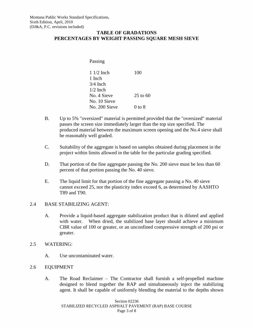
Montana Public Works Standard Specifications,
Sixth Edition, April, 2010
(DJ&A, P.C. revisions included)
Section 02236
STABILIZED RECYCLED ASPHALT PAVEMENT (RAP) BASE COURSE
Page 3 of 8
TABLE OF GRADATIONS
PERCENTAGES BY WEIGHT PASSING SQUARE MESH SIEVE
Passing
1 1/2 Inch 100
1 Inch
3/4 Inch
1/2 Inch
No. 4 Sieve 25 to 60
No. 10 Sieve
No. 200 Sieve 0 to 8
B. Up to 5% "oversized" material is permitted provided that the "oversized" material
passes the screen size immediately larger than the top size specified. The
produced material between the maximum screen opening and the No.4 sieve shall
be reasonably well graded.
C. Suitability of the aggregate is based on samples obtained during placement in the
project within limits allowed in the table for the particular grading specified.
D. That portion of the fine aggregate passing the No. 200 sieve must be less than 60
percent of that portion passing the No. 40 sieve.
E. The liquid limit for that portion of the fine aggregate passing a No. 40 sieve
cannot exceed 25, nor the plasticity index exceed 6, as determined by AASHTO
T89 and T90.
2.4 BASE STABILIZING AGENT:
A. Provide a liquid-based aggregate stabilization product that is diluted and applied
with water. When dried, the stabilized base layer should achieve a minimum
CBR value of 100 or greater, or an unconfined compressive strength of 200 psi or
greater.
2.5 WATERING:
A. Use uncontaminated water.
2.6 EQUIPMENT
A. The Road Reclaimer – The Contractor shall furnish a self-propelled machine
designed to blend together the RAP and simultaneously inject the stabilizing
agent. It shall be capable of uniformly blending the material to the depths shown
Montana Public Works Standard Specifications,
Sixth Edition, April, 2010
(DJ&A, P.C. revisions included)
Section 02236
STABILIZED RECYCLED ASPHALT PAVEMENT (RAP) BASE COURSE
Page 4 of 8
in the Plans or as directed by the Engineer. This machine shall have automatic
depth and cross-slope controls and maintain a constant cutting depth. The
automatic depth controls shall maintain the cutting depth to within plus or minus
¼ inch of the depth shown on the Plans. The Road Reclaimer shall be fitted with
equipment capable of adequately mixing the RAP material while injecting the
base stabilizing agent water mixture as detailed in the Mixing/Injecting portion of
this specification. The equipment shall provide a positive means for accurately
controlling the rate of flow and total delivery of the base stabilizing agent water
mixture in relation to the speed of the reclaiming machine and quantity of
material being blended. The injection system shall accurately and uniformly add
the specified percent of water to the binder. The equipment shall be fitted with a
sampling nozzle to provide field samples of the base stabilizing agent water
mixture.
B. Mixing/Injecting- The Reclaiming Machine shall be capable of injecting the
stabilizing agent and automatically metering it with a variation of not more than
plus or minus 0.2 percent by weight of the agent. The unit shall be equipped with
facilities so that the Contractor can verify and calibrate these items by a method
acceptable to the Engineer.
C. Water Additive Systems- The Reclaimer shall be equipped with a system capable
of adding stabilizer/water mixture for material compaction, from bulk tankers,
directly into the mixing chamber.
D. Controls for Liquid Additive Systems- All pumps shall be separately controlled
by the automatic system in the operator’s cabin. During automatic operation, the
system will allow liquids to be added only when the machine is in motion.
E. The pumps shall have a separate hydraulic drive systems.
F. The control system shall be capable of fully automated operation, as well as
manual operation, when injecting the liquids to be add/mixed. All functions shall
be controlled from the operation’s station including automatic nozzle cleaning,
partial spray bar use, and on-the-fly changes to the quantities of the materials
being added. Non-contact flow meters shall be employed to measure liquid
volumes and the control systems shall be proportional to the machines advance
speed and shall be capable of maintaining accurate mixing regardless of changes
in the machines working speed.
G. There shall be a system allowing the operator to verify that the nozzles on the
spray bars are open and working from the operator’s cabin.
H. There shall be provided a gallon per minute gauge to indicate instantaneous flow.
PART 3: EXECUTION
Montana Public Works Standard Specifications,
Sixth Edition, April, 2010
(DJ&A, P.C. revisions included)
Section 02236
STABILIZED RECYCLED ASPHALT PAVEMENT (RAP) BASE COURSE
Page 5 of 8
3.1 GENERAL
A. Before placing the RAP base course layer, smooth, shape, and compact the
surface of the underlying subgrade to the cross section shown on the plans before
placing the base course. The subgrade shall be compacted to a minimum of 90
percent of ASTM D1557, or 95 percent of ASTM D698. In areas where the
trail is to be constructed on existing highway embankment, the contractor
will not use vibratory rolling methods to compact the subgrade. If the
contractor is experiencing difficulty achieving compaction of the subgrade
utilizing non-vibratory methods, the contractor will notify the Engineer who
will determine alternative compaction methods.
B. Do not place base course on a wet or muddy subgrade. Complete at least one area
of finished and accepted subgrade before the placing of any base course layer.
3.2 PLACEMENT AND SPREADING
A. Deposit and spread each load of material on the prepared subgrade continuously
without interruption. Discontinue operating haul units over subgrade if the haul
units damage the subgrade.
B. Deposit and spread the material in a uniform layer, without segregation, to a loose
depth so that when compacted, and making allowance for the stabilizer to be
blended on the road, the layer has the specified 4-inch thickness.
C. Spread material using dump boards, spreader boxes, or vehicles equipped to
distribute the material in a uniform layer. The material may be deposited in
windrows mixed and spread as described below.
D. Construct each layer meeting these requirements. Blade smooth and thoroughly
compact each layer as specified before placing the succeeding layer.
E. If segregation or moisture problems exist, or if the material was placed on the
road in windrows, thoroughly blade-mix the material of the affected layer by
alternately blading to the center and back to the edges of the street.
F. Uniformly add water, when required, on site and place in amounts required to
compact the material as necessary to aid in densification and to limit segregation.
Maintain an adequate water supply during the work. Assure the equipment used
for watering is of the capacity and design to provide uniform water application.
G. Apply water during the work to control dust and to maintain the base course in a
damp condition in accordance with Section 01500 under Dust Control.
Montana Public Works Standard Specifications,
Sixth Edition, April, 2010
(DJ&A, P.C. revisions included)
Section 02236
STABILIZED RECYCLED ASPHALT PAVEMENT (RAP) BASE COURSE
Page 6 of 8
H. Water required for compacting base gravel may be obtained from the municipal
system if approved by the owner, or from other sources.
3.3 STABILIZATION AND COMPACTION
A. The RAP base material shall be blended to in one operation so that the entire mass
of material is uniformly blended/mixed. Depending on the width of the reclaimer,
it may take more than one pass horizontally to cover the entire width of the trail.
B. The blended RAP material shall meet the previous gradation requirements listed
under Materials. In the event that the reclamation process extends slightly into the
existing sand and gravel fill layer, up to approximately 5 percent oversize
particles (greater than 2 inches in size) will be allowed in the final base layer
product.
C. During the stabilization operation the Contractor shall physically dig down,
approximately every 1000 feet to check the blending depth and visually verify
that a 4-inch stabilized depth is being achieved. Additional depth verifications
will be performed by the owner representative at intervals determined by the
engineer.
D. The reclaimer shall have the capacity to uniformly inject the stabilizing agent and
water mixture through the reclamation machine into the stabilized layer in one
pass. Spraying the product onto the surface or on windrows is not allowed.
E. The stabilizing product shall be injected at the manufacturers recommended rate.
F. An owner’s representative should perform moisture tests in advance of
stabilization at intervals specified by the Engineer to determine the moisture
content of the material to be stabilized. The results of the moisture tests should be
used in conjunction with moisture/density values, determined using ASTM D698
or D1557, to determine the application rate of the stabilizing product.
G. The contractor shall utilize a vibratory steel drum roller capable of producing 250
lbs/in of drum width or a pneumatic tired roller (self propelled or towed) having a
compacting width of 5 feet or more and sufficient mass to provide 100-250 lbs./in
of rolling width. In areas where the trail is to be constructed on existing
highway embankment, the contractor will not use vibratory rolling methods
to compact the subgrade. If the contractor is experiencing difficulty
achieving compaction of the subgrade utilizing non-vibratory methods, the
contractor will notify the Engineer who will determine alternative
compaction methods..
H. During the compaction process, the contractor shall provide sufficient water so
the stabilized mixture will be at +/- 2 percent of the optimum moisture content per
ASTM D698. If a nuclear density gauge is used to determine the in-situ density
and moisture content, care should be taken to correct for the asphalt content of the
Montana Public Works Standard Specifications,
Sixth Edition, April, 2010
(DJ&A, P.C. revisions included)
Section 02236
STABILIZED RECYCLED ASPHALT PAVEMENT (RAP) BASE COURSE
Page 7 of 8
stabilized material. All stabilized material shall be blended, spread, watered,
compacted, and shaped, by the end of each workday.
I. Following stabilization and prior to paving, the contractor shall maintain the
reclaimed surface so it is free of ruts, washboards, and potholes. This may require
application of water and using a scarifying blade on a road grader. Stabilized
material with a “wash board” surface condition shall be scarified to a depth below
that lowest surface of the wash boarded area and recompacted immediately prior
to paving. This work shall be performed at no additional cost to the Owner. Any
costs associated with maintaining this surface is incidental to Stabilized Recycled
Asphalt Pavement (RAP) Base Course.
J. The contractor shall allow the stabilized layer to cure for a minimum of 10
calendar days prior to paving. Depending on the product used, traffic might be
allowed to travel on the surface upon completion of compaction. Should the
treated surface be exposed to significant rainfall (more than 4 hours of continuous
rainfall per day) during the recommended 10-day cure period, the reclaimed
material should be allowed a minimum of one additional ‘dry’ day (no rainfall) to
cure for each day where rain fell for more than 4 hours.
K. Prior to paving, water shall be applied when directed by the engineer for dust
control.
3.4 SURFACE TOLERANCES
A. The base course surface when finished and tested with a 10-foot straight edge
placed on the surface with its center line parallel to the center line of the street,
will not have a surface deviation more than 0.02 feet (0.6 centimeters) at any
point from the staked elevations, and the sum of the deviations from two points
not more than 30 feet (9.0 meters) apart cannot exceed 0.02 feet (0.6 centimeters).
B. If patching of the stabilized base course is necessary to meet the tolerances,
perform patching using methods and mateials approved by the Engineer.
PART 4: MEASUREMENT AND PAYMENT
4.1 MEASUREMENT
A. RECYCLED ASPHALT PAVEMENT (RAP) BASE COURSE
1. Measure recycled asphalt pavement base course in its final compacted and
treated position. Compute the quantity using the average end areas
multiplied by the horizontal distance along a centerline or reference line
between the end areas. Deduct any quantity outside the designed or staked
limits. Do not measure the treatment of the base course or haul separately.

Montana Public Works Standard Specifications,
Sixth Edition, April, 2010
(DJ&A, P.C. revisions included)
Section 02236
STABILIZED RECYCLED ASPHALT PAVEMENT (RAP) BASE COURSE
Page 8 of 8
Treatment and haul are considered incidental to the construction of the
base course layer.
4.2 PAYMENT
A. The accepted quantities will be paid for at the contract unit price per unit of
measurement as reflected in the bid schedule.
END OF SECTION

APPENDIX G