Embed Size (px)
Citation preview
THREE-DIMENSIONAL NUMERICAL MODEL OF
CONSTRUCTION PROCESS FOR EMBEDDED
TUNNEL OPENING OF DONGHU METRO STATION
Li Hongjian1
ABSTRACT
The Donghu station of No.6 line of Guangzhou rail transit has divided two parts, one is embedded excavation part, and the other is Open excavation part. The kilometer of embedded excavation part is from k13+462.752 to k13+519.452. The tunnel crown is located 19 m below the ground surface. Stratums are mix-filled soil, alluvial deposit to flooded alluvial deposit, eluvium and all regolith to medium regolith from the top down. The largest span of tunnel is 20 m. Its largest height is 10.349 m. Because the tunnel has large span and section, the construction is very difficult. In order to control the surface settlement and ensure the security of tunnel, the FEA method is used to analyze the construction process to find the rationality of construction method and support method. A three-dimensional numerical simulation model analyzes the construction process of the tube pre-support and center drift method in Donghu station by FLAC-3D in this paper. The results indicate that the reinforced and construction method can ensure the safety of construction, and control the surface settlement. The final conclusions are two: (1) the surface settlement and displacement are small and the tunnel is steady in the construction process. (2) The main step of influencing the surface settlement and crown settlement are step I, step IV and removing of the temporary supporter. So the supporter must be installed in time and reinforced the strength. The distance which is from working face to temporary supporter must be more than two times span of tunnel.
KEY WORDS
metro station, surface settlement, stability, FLAC-3D, numerical analysis
INTRODUCTION
The Donghu station of No.6 line of Guangzhou rail transit has divided two parts, one is embedded excavation part, and the other is Open excavation part. The kilometer of embedded excavation part is from k13+462.752 to k13+519.452. It passes through the Donghu road. The tunnel crown is located 19 m below the ground surface. Stratums are mix-filled soil, alluvial deposit to flooded alluvial deposit, eluvium and all regolith to medium regolith from the top down. The largest span of tunnel is 20 m. Its largest height 1 Lectuer, School of Civil Engineering, Shijiazhuang Railway Institute, Shijiazhuang 050043, China, Phone +860311/87935526, Fax +860311/87935526, [email protected]
June 14-16, 2006 - Montréal, CanadaJoint International Conference on Computing and Decision Making in Civil and Building Engineering
Page 192
is 10.349 m. Because the tunnel has large span and section, the construction is very difficult. But must control the surface settlement and ensure the security of tunnel. The center drift method is adopted.
In actual tunnel construction process, the tunnel support parameters, excavation method, cycle footage and the various joint of all process have the tremendous influence to the stratum disturbance as well as the surface settlement. Therefore, a three-dimensional numerical simulation model analyzes the construction process of the pipe-roof pre-support and center drift method in Donghu station by FLAC-3D.
CALCULATING MODEL
FLAC-3D (Three Dimensional Fast Lagrangian Analysis of Continua)is now popular and advanced software in the world. The software is specially used to solve the soil mechanics questions, which is a Large-scale commercial finite difference program. It was developed by Itasca Consulting Group Inc. of USA.
The scope of calculating model is: the horizontal direction is 4 times tunnel span form tunnel center to the model boundary. The vertical direction is 4 times tunnel height from tunnel bottom to base boundary. The height above tunnel is from the tunnel crown to natural ground surface. The model size (xyz) is 160m, 70.31m and 21m. The boundary conditions are as follows: ground surface is free, the left boundary and right boundary are fixed at x-axis direction, front boundary and rear boundary fixed at z-axis direction, and base boundary is fixed at y-axis direction. The uniform load of road surface is 10kpa. There are 38346 zones elements in this numerical model. An elastic-perfectly-plastic model using the Mohr-Coulomb failure criterion was adopted in this study.
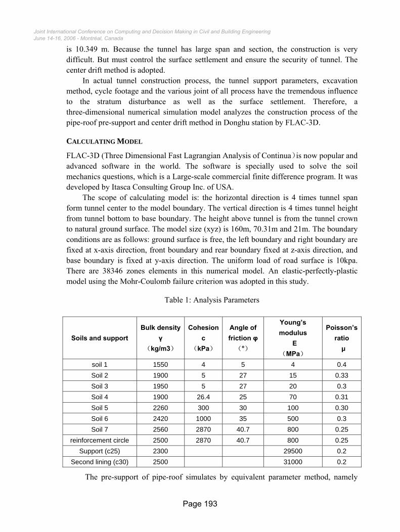
Table 1: Analysis Parameters
The pre-support of pipe-roof simulates by equivalent parameter method, namely
Soils and support Bulk density
γ (kg/m3)
Cohesion c
(kPa)
Angle of friction φ (°)
Young’s modulus
E (MPa)
Poisson’s ratio µ
soil 1 1550 4 5 4 0.4 Soil 2 1900 5 27 15 0.33 Soil 3 1950 5 27 20 0.3 Soil 4 1900 26.4 25 70 0.31 Soil 5 2260 300 30 100 0.30 Soil 6 2420 1000 35 500 0.3 Soil 7 2560 2870 40.7 800 0.25
reinforcement circle 2500 2870 40.7 800 0.25 Support (c25) 2300 29500 0.2
Second lining (c30) 2500 31000 0.2
June 14-16, 2006 - Montréal, CanadaJoint International Conference on Computing and Decision Making in Civil and Building Engineering
Page 193
through enhancing the parameter of pipe-roof reinforcement region to come equivalent simulation. The physics mechanics parameter of reinforcement circle enhances a rank according to the locus level. The reinforcement circle scope is pipe-roof construction region of tunnel arch; reinforcement circle thickness is 200mm.
ANALYSIS PARAMETERS The stratum, reinforcement circle and support structure parameter are list in table 1.
ANALYSIS BEHAVIOUR
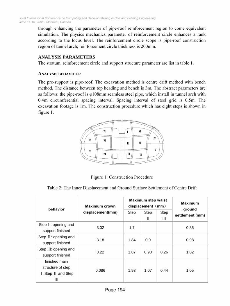
The pre-support is pipe-roof. The excavation method is centre drift method with bench method. The distance between top heading and bench is 3m. The abstract parameters are as follows: the pipe-roof is φ108mm seamless steel pipe, which install in tunnel arch with 0.4m circumferential spacing interval. Spacing interval of steel grid is 0.5m. The excavation footage is 1m. The construction procedure which has eight steps is shown in figure 1.
Figure 1: Construction Procedure
Table 2: The Inner Displacement and Ground Surface Settlement of Centre Drift
Maximum step waist displacement(mm)
behavior Maximum crown
displacement(mm) Step Ⅰ
Step Ⅱ
Step Ⅲ
Maximum ground
settlement (mm)
StepⅠ: opening and support finished
3.02 1.7 0.85
Step Ⅱ: opening and support finished
3.18 1.84 0.9 0.98
Step Ⅲ: opening and support finished
3.22 1.87 0.93 0.26 1.02
finished main structure of step
Ⅰ,Step Ⅱ and Step Ⅲ
0.086 1.93 1.07 0.44 1.05
June 14-16, 2006 - Montréal, CanadaJoint International Conference on Computing and Decision Making in Civil and Building Engineering
Page 194
ANALYSIS RESULTS
THE INNER DISPLACEMENT AND GROUND SURFACE SETTLEMENT OF CENTRE DRIFT The inner displacement and ground surface settlement of centre drift is listed in table 2.
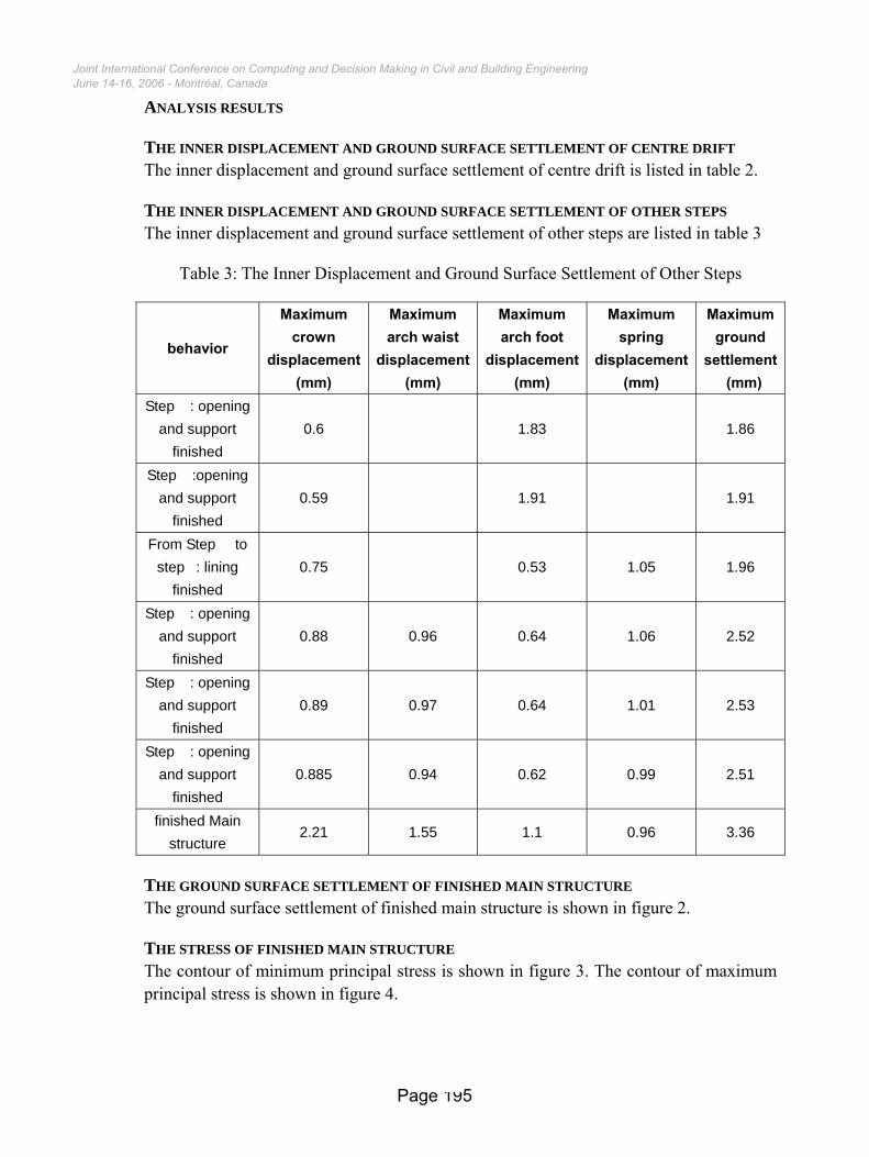
THE INNER DISPLACEMENT AND GROUND SURFACE SETTLEMENT OF OTHER STEPS The inner displacement and ground surface settlement of other steps are listed in table 3
Table 3: The Inner Displacement and Ground Surface Settlement of Other Steps
behavior
Maximum crown
displacement (mm)
Maximum arch waist
displacement(mm)
Maximum arch foot
displacement(mm)
Maximum spring
displacement (mm)
Maximum ground
settlement (mm)
Step �: opening and support
finished 0.6 1.83 1.86
Step �:opening and support
finished 0.59 1.91 1.91
From Step � to step�: lining
finished 0.75 0.53 1.05 1.96
Step �: opening and support
finished 0.88 0.96 0.64 1.06 2.52
Step �: opening and support
finished 0.89 0.97 0.64 1.01 2.53
Step �: opening and support
finished 0.885 0.94 0.62 0.99 2.51
finished Main structure
2.21 1.55 1.1 0.96 3.36
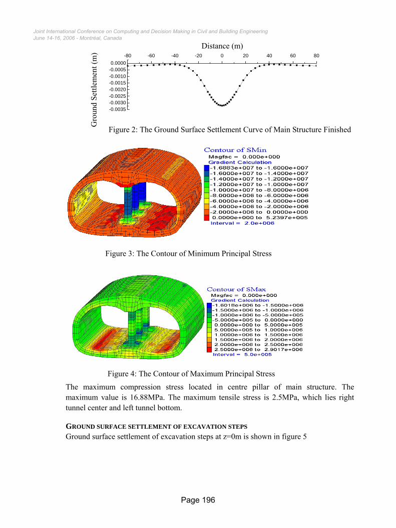
THE GROUND SURFACE SETTLEMENT OF FINISHED MAIN STRUCTURE The ground surface settlement of finished main structure is shown in figure 2.
THE STRESS OF FINISHED MAIN STRUCTURE The contour of minimum principal stress is shown in figure 3. The contour of maximum principal stress is shown in figure 4.
June 14-16, 2006 - Montréal, CanadaJoint International Conference on Computing and Decision Making in Civil and Building Engineering
Page 195
-80 -60 -40 -20 0 20 40 60 80
-0.0035-0.0030-0.0025-0.0020-0.0015-0.0010-0.00050.0000
地表沉降(m)
距车站中心线相对距离(m)
Figure 2: The Ground Surface Settlement Curve of Main Structure Finished
The maximum compression stress located in centre pillar of main structure. The maximum value is 16.88MPa. The maximum tensile stress is 2.5MPa, which lies right tunnel center and left tunnel bottom.
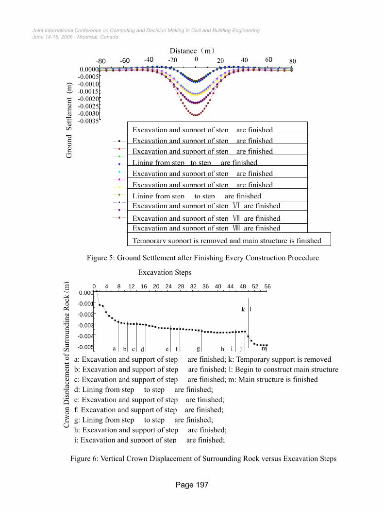
GROUND SURFACE SETTLEMENT OF EXCAVATION STEPS Ground surface settlement of excavation steps at z=0m is shown in figure 5
Figure 3: The Contour of Minimum Principal Stress
Distance (m)
Gro
und
Settl
emen
t (m
)
Figure 4: The Contour of Maximum Principal Stress
June 14-16, 2006 - Montréal, CanadaJoint International Conference on Computing and Decision Making in Civil and Building Engineering
Page 196
0 4 8 12 16 20 24 28 32 36 40 44 48 52 56
-0.003
-0.002
-0.001
0.000
lk拱顶围岩
开挖步
Excavation Steps
undi
ng R
ock
(m)
e
Distance(m) -80 -60 -40 -20 0 20 40 60 80
-0.0035 -0.0030 -0.0025 -0.0020 -0.0015 -0.0010 -0.0005 0.0000
Ⅰ步开挖支护完毕 Ⅱ步开挖支护完毕 Ⅲ步开挖支护完毕 Ⅰ至Ⅲ步主体结构施工完毕 Ⅳ步开挖支护完毕 Ⅴ步开挖支护完毕 Ⅳ至Ⅴ步二次衬砌施工完毕 Ⅵ步扩挖支护完毕 Ⅶ步扩挖支护完毕 Ⅷ步扩挖支护完毕 临时支护拆除,主体结构施工完毕
Gro
und
Settl
emen
t (m
)
Excavation and support of step� are finishedExcavation and support of step� are finishedExcavation and support of step� are finishedLining from step�to step � are finishedExcavation and support of step� are finishedExcavation and support of step� are finished
Excavation and support of step Ⅵ are finishedLining from step � to step � are finished
Excavation and support of step Ⅷ are finishedTemporary support is removed and main structure is finished
Excavation and support of step Ⅶ are finished
Figure 5: Ground Settlement after Finishing Every Construction Procedure
June 14-16, 2006 - Montréal, CanadaJoint International Conference on Computing and Decision Making in Civil and Building Engineering
-0.005
-0.004
mjihgfec 位移/ m
a b d
Crw
on D
ispl
acem
ent o
f Sur
ro
a: Excavation and support of step � are finished; k: Temporary support is removed b: Excavation and support of step � are finished; l: Begin to construct main structurc: Excavation and support of step � are finished; m: Main structure is finished d: Lining from step � to step � are finished; e: Excavation and support of step� are finished; f: Excavation and support of step� are finished; g: Lining from step � to step � are finished; h: Excavation and support of step � are finished;
Figure 6: Vertical Crown Displacement of Surrounding Rock versus Excavation Steps
i: Excavation and support of step � are finished;
Page 197
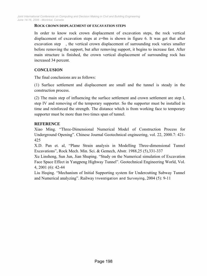
ROCK CROWN DISPLACEMENT OF EXCAVATION STEPS
In order to know rock crown displacement of excavation steps, the rock vertical displacement of excavation steps at z=0m is shown in figure 6. It was get that after excavation step �, the vertical crown displacement of surrounding rock varies smaller before removing the support, but after removing support, it begins to increase fast. After main structure is finished, the crown vertical displacement of surrounding rock has increased 34 percent.
CONCLUSION
The final conclusions are as follows:
(1) Surface settlement and displacement are small and the tunnel is steady in the construction process.
(2) The main step of influencing the surface settlement and crown settlement are step I, step IV and removing of the temporary supporter. So the supporter must be installed in time and reinforced the strength. The distance which is from working face to temporary supporter must be more than two times span of tunnel.
REFERENCE Xiao Ming. “Three-Dimensional Numerical Model of Construction Process for Underground Opening”. Chinese Journal Geotechnical engineering, vol. 22, 2000.7: 421- 425 X.D. Pan et. al, “Plane Strain analysis in Modelling Three-dimensional Tunnel Excavations”, Rock Mech. Min. Sci. & Gemech, Abstr. 1988,25 (5),331-337 Xu Linsheng, Sun Jun, Jian Shuping. “Study on the Numerical simulation of Excavation Face Space Effect in Yangpeng Highway Tunnel”. Geotechnical Engineering World, Vol. 4, 2001 (6): 42-44 Liu Heqing. “Mechanism of Initial Supporting system for Undercutting Subway Tunnel and Numerical analyzing”. Railway Investigation and Surveying, 2004 (5): 9-11
June 14-16, 2006 - Montréal, CanadaJoint International Conference on Computing and Decision Making in Civil and Building Engineering
Page 198