Embed Size (px)
Citation preview
June 13th-14th, 2002International Systems Fire Protection
Working Group CAA House - London, UK
Modeling of Inert Gas Distribution in Commercial
Transport Fuel Tanks
William M CavageProject Manager - Fuel Tank Inerting
FAA AAR-440, Fire Safety R&D Branch
AAR-422 Fire Safety R&D
Inert Gas Distribution Modeling___________________________________
Outline
• Background• Preliminary Model Methods
• Scale Tank Testing
• Engineering Model
• Summary
AAR-422 Fire Safety R&D
Inert Gas Distribution Modeling___________________________________
Background• FAA Would Like to Develop Cost Effective Methods of
Modeling Inert Gas Distribution in Commercial Transport Fuel Tanks
• Developed a Scale Tank Model of the 747SP CWT – Made From Plywood Using NTSP Shepard Report Drawings
– Variable NEA Deposit Capabilities, Oxygen Analyzer in Each Bay
– Preliminary Results Didn’t Model Gas Distribution Well
• Developed Multiple Bay Inert Gas Distribution Engineering Model of 747SP CWT – Models 6 Bay Tank in Test Article Venting Config. (half blocked)
– Based on Ullage Washing Model

AAR-422 Fire Safety R&D
Inert Gas Distribution Modeling___________________________________
Inert Gas Distribution Modeling• Preliminary Models
– Original Simple Inerting Model Developed by Ivor Thomas (FAA CSTA for Fuel Systems)
• Tracks the Volume of Oxygen In and Out of a Tank and Calculates Oxygen Concentration Given the Tank Volume
• Uses a Basic Spreadsheet Layout and Runs Instantaneously Given the Volume of the Tank, The Flow Rate and Purity of the NEA
– Basic Formula for Model
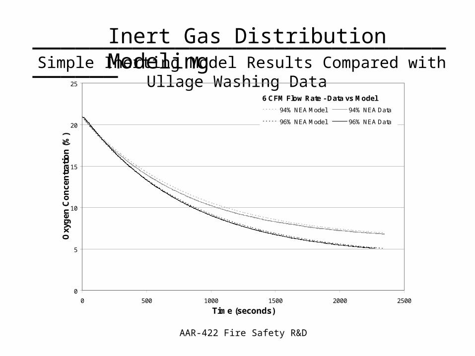
– Model Results Compared Well with Ullage Washing Data
TankONEANEAOO VttVQtIGOFQtVtV /)1()1()(222
Tank
O
V
tVtOTank
)()]([ 2
2
AAR-422 Fire Safety R&D
Inert Gas Distribution Modeling___________________________________Simple Inerting Model Results Compared with Ullage Washing Data
0
5
10
15
20
25
0 500 1000 1500 2000 2500
Time (seconds)
Oxy
gen
Co
nce
ntr
atio
n (
%)
94% NEA Model 94% NEA Data
96% NEA Model 96% NEA Data
6 CFM Flow Rate - Data vs Model
AAR-422 Fire Safety R&D
Inert Gas Distribution Modeling___________________________________
Scale CWT Tests• Original Plywood Model Results Encouraging, But
NEA Distribution Did Not Compare Well with Full-Scale Data
• Made Several Improvements to Scale Tank– Better Modeling of Vent System Cross Sectional Flow Areas
– Ensured Lid Did Not Leak Around Bay Tops which Would Alter Flow Pattern
• Performed Additional Testing – Scale Tank Inert Gas Distribution Results Compared Very Well to
Data Acquired on 747SP Full-Scale Test Article
– Additional Testing Planned for Different Deposit Methods (Onboard System)

AAR-422 Fire Safety R&D
Inert Gas Distribution Modeling___________________________________Scale Plywood CWT Model
AAR-422 Fire Safety R&D
Inert Gas Distribution Modeling___________________________________
0
5
10
15
20
25
0 0.2 0.4 0.6 0.8 1 1.2 1.4 1.6
Overall VTE
Oxy
gen
Co
nce
ntr
atio
n (
% v
ol)
Bay 1 Bay 1
Bay 2 Bay 2
Bay 3 Bay 3
Bay 4 Bay 4
Bay 5 Bay 5
Bay 6 Bay 6
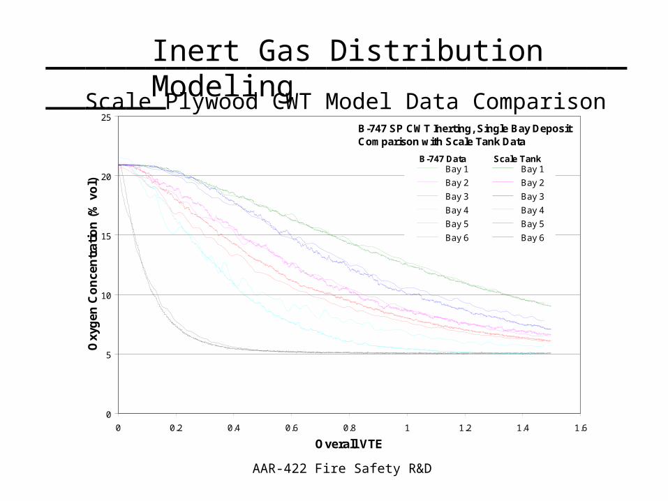
B-747 SP CWT Inerting, Single Bay DepositComparison with Scale Tank Data
B-747 Data Scale Tank
Scale Plywood CWT Model Data Comparison
AAR-422 Fire Safety R&D
Inert Gas Distribution Modeling___________________________________
Multiple-Bay Inerting Engineering Model• Model Calculates Inert Gas Distribution in 6 Bay Tank,
in terms of Oxygen Concentration Evolution, Given NEA Purity and Bay Deposit Flow Rates– Based on Original Inerting Model by Ivor Thomas which Tracks
Oxygen In and Out of Each Bay Assuming Perfect Mixing During the Time Step
– Assumes an “Outward” Flow Pattern and Splits Flow into a Bay to Adjacent Bays Using Out Flow Area Relationships
– Presently Does Half Blocked Venting Case Only
• Compared with Full-Scale Test Article– Must Run ACMs to Obtain Data that Agrees with Engineering Model
(Which Assumes Perfect Mixing)
– Agrees Best for Single Deposit Case Compared with Scale Tank Data
AAR-422 Fire Safety R&D
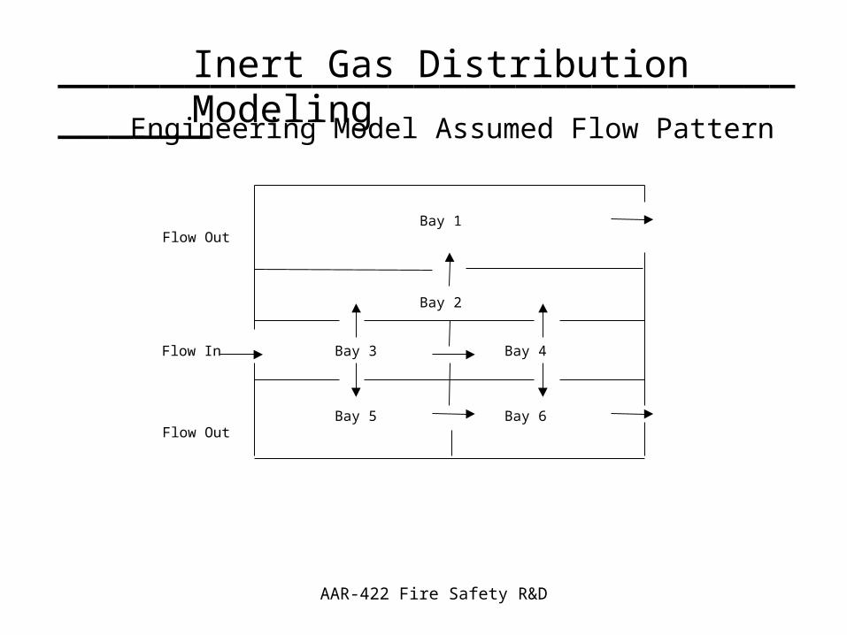
Inert Gas Distribution Modeling___________________________________Engineering Model Assumed Flow Pattern
Bay 1Flow Out
Bay 2
Flow In Bay 3 Bay 4
Bay 5 Bay 6Flow Out
AAR-422 Fire Safety R&D
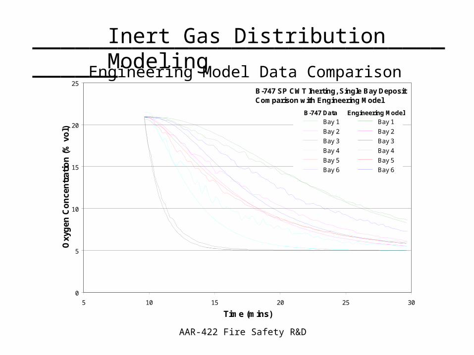
Inert Gas Distribution Modeling___________________________________Engineering Model Data Comparison
0
5
10
15
20
25
5 10 15 20 25 30
Time (mins)
Oxy
gen
Co
nce
ntr
atio
n (
% v
ol)
Bay 1 Bay 1
Bay 2 Bay 2
Bay 3 Bay 3
Bay 4 Bay 4
Bay 5 Bay 5
Bay 6 Bay 6
B-747 SP CWT Inerting, Single Bay DepositComparison with Engineering Model
B-747 Data Engineering Model
AAR-422 Fire Safety R&D
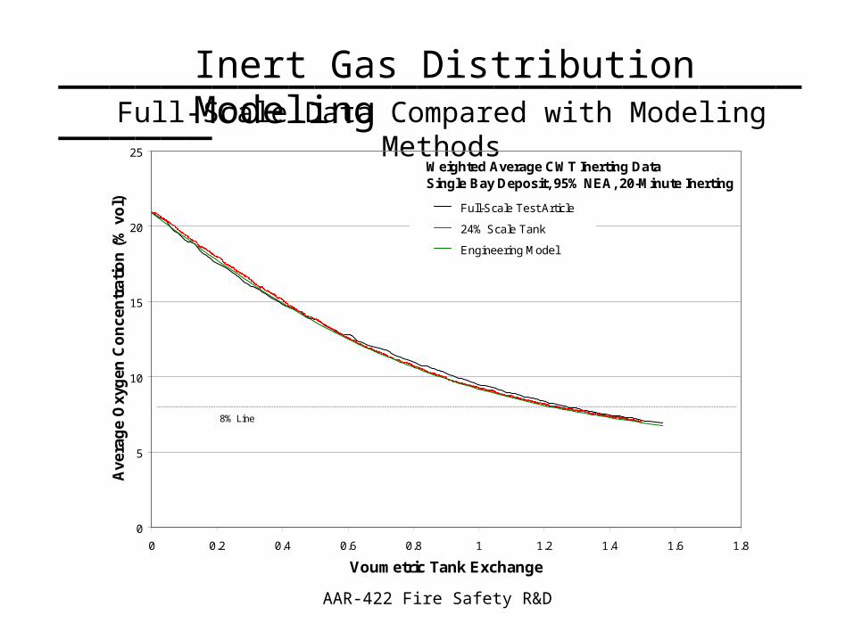
Inert Gas Distribution Modeling___________________________________Full-Scale Data Compared with Modeling Methods
0
5
10
15
20
25
0 0.2 0.4 0.6 0.8 1 1.2 1.4 1.6 1.8
Voumetric Tank Exchange
Ave
rag
e O
xyg
en C
on
cen
trat
ion
(%
vo
l) Full-Scale Test Article
24% Scale Tank
Engineering Model
Weighted Average CWT Inerting DataSingle Bay Deposit, 95% NEA, 20-Minute Inerting
8% Line

AAR-422 Fire Safety R&D
Inert Gas Distribution Modeling___________________________________
Summary• Scale Tank Testing Produced Good Results when
Compared with the “Good Mixing” Full-Scale Testing– Cost Effective Modeling Method
• Simple Engineering Modeling Methods Can Produce Fair Results in a Very Cost Effective Way – Additional Work Needed to Improve Model for Multiple
Deposits
• Both Methods Predict VTE Required (Amount of NEA) Very Well, Given a Highly Localized Deposit