Embed Size (px)
Citation preview
MONTHLY Volume II, Issue 6, June 2006 POSITIONING, NAVIGATION AND BEYOND
No: DL(E)-01/5079/05-07 RNI: DELENG/2005/15153
Rs.100
ISSN
0973-2
136
MyRTKnet Get set and go!
A new move(ment)India’s map policy guidelines
MyRTKnet: Get set and go! DATO’ HAMID ALI, AHMAD FAUZI NORDIN, DR SAMAD HJ ABU, CHANG LENG
HUA 6 A new move(ment) JG KRISHNAYYA AND GEORGE CHO 20 His coordinates CHRISTIAN KNOLL
25 Space-based positioning system with no on-board atomic clocks FABRIZIO TAPPERO,
ANDREW DEMPSTER, TOSHIAKI IWATA 26 Going hand in hand MADHAV N KULKARNI AND DM SATALE 30
June 2006 3
CONTENTS – VOLUME 2, ISSUE 6, JUNE 2006
cGIT 28A Pocket D, SFS Mayur Vihar Phase III, Delhi 110 096, India. Telefax +91 11 22632607, 98107 24567, 98102 33422 Email [information] [email protected] [editorial] [email protected] [advertising] [email protected] [subscriptions] [email protected] Web www.mycoordinates.org
This issue has been made possible by the support and good wishes of the following individuals and companies Ahmad Fauzi Nordin, Andrew Dempster, Chang Leng Hua, Christian Knoll, DM Satale, Fabrizio Tappero, George Cho, Dato’ Hamid Ali, JG Krishnayya, Jim Smith, Madhav N Kulkarni, Muneendra Kumar, Dr Samad Hj Abu, Toshiaki Iwata and; Contex, HP, Leica, Navcom, Traceme, Topcon, Trimble; and many others.
Coordinates is an initiative of cGIT that aims to broaden the scope of positioning, navigation and related technologies. cGIT does not neccesarily subscribe to the views expressed by the authors in this magazine and may not be held liable for any losses caused directly or indirectly due to the information provided herein. © cGIT, 2005. Reprinting with permission is encouraged; contact the editor for details. Annual subscription (12 issues) [India] Rs.1,200 [Overseas] US$80
Printed and published by Sanjay Malaviya on behalf of Centre for Geoinformation Technologies (cGIT) at A221 Mangal Apartments, Vasundhara Enclave, Delhi 110096, India. Editor Bal Krishna | Owner Centre for Geoinformation Technologies | Designer TSA Effects, www.tsa.in | Printer Sonu Printer, A110 DDA Sheds, Okhla, New Delhi, India.
This issue of Coordinates is of 40 pages, including cover.
Articles
MyRTKnet: Get set and go! DATO’ HAMID ALI, AHMAD FAUZI NORDIN, DR SAMAD HJ ABU, CHANG LENG HUA
6 A new move(ment) JG KRISHNAYYA AND GEORGE CHO 20 Space-based positioning system with
no on-board atomic clocks FABRIZIO TAPPERO, ANDREW DEMPSTER, TOSHIAKI IWATA 26 Going hand in
hand MADHAV N KULKARNI AND DM SATALE 30 India’s phone coordinates MUNEENDRA KUMAR 36
Columns
My coordinates EDITORIAL 4 News GALILEO UPDATE 14 GIS 14 INDUSTRY 16 LBS 18
GPS 18 REMOTE SENSING 24 His coordinates CHRISTIAN KNOLL 25 History JIM SMITH 34
Conference GEODESY IN SURVEYING 38 Mark your calendar JUNE TO NOVEMBER 38
4 June 2006
Chief advisor Muneendra Kumar PhD, Chief Geodesist (Retired), US National Geospatial Intelligence Agency, USA Advisors Naser El-Sheimy PEng, CRC Professor, Department of Geomatics Engineering, The University of Calgary Canada, George Cho Associate Professor in GIS and the Law, University of Canberra, Australia, Prof Madhav N Kulkarni Department of Civil Engineering, Indian Institute of Technology Bombay, India Dr Abbas Rajabifard Deputy Director, Centre for SDI and Land Administration, University of Melbourne, Australia, Luiz Paulo Souto Fortes PhD Associate Director of Geosciences, Brazilian Institute of Geography and Statistics - IBGE, Brazil, John Hannah Professor, School of Surveying, University of Otago, New Zealand
MYCOORDINATES
The SHARP edge of Mt Everest
David Sharp was left to die.
Many saw him.
They didn’t do anything.
Perhaps they could not.
Perhaps it was ‘impossible’ to do anything there.
They continued climbing…
Conquered Mt Everest.
Sir Edmund Hillary is outraged.
He knows what they lost.
But it happens.
Everyday and everywhere.
People are allowed to die.
Who cares?
The ‘ultimate’ is just to be on the top.
Let us climb up and up.
Leaving those who can’t.
Can you?
Bal Krishna, Editor

June 2006 5
6 June 2006
SURVEYING
MyRTKnet: Get set and go! MyRTK network is an effort to use real-time survey technology for the enhancement of many services and dissemination of various geodetic products
DATO’ HAMID ALI, AHMAD FAUZI NORDIN, DR SAMAD HJ ABU, CHANG LENG HUA
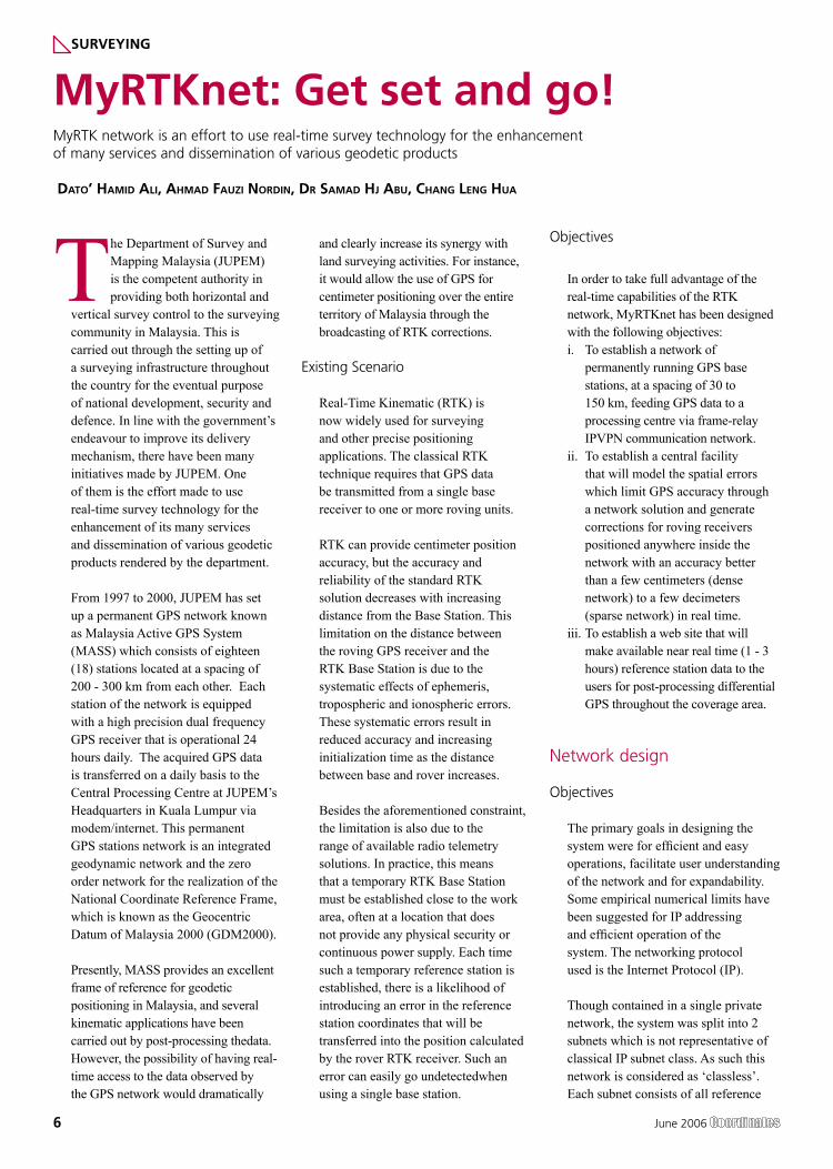
The Department of Survey and Mapping Malaysia (JUPEM) is the competent authority in providing both horizontal and
vertical survey control to the surveying community in Malaysia. This is carried out through the setting up of a surveying infrastructure throughout the country for the eventual purpose of national development, security and defence. In line with the government’s endeavour to improve its delivery mechanism, there have been many initiatives made by JUPEM. One of them is the effort made to use real-time survey technology for the enhancement of its many services and dissemination of various geodetic products rendered by the department.
From 1997 to 2000, JUPEM has set up a permanent GPS network known as Malaysia Active GPS System (MASS) which consists of eighteen (18) stations located at a spacing of 200 - 300 km from each other. Each station of the network is equipped with a high precision dual frequency GPS receiver that is operational 24 hours daily. The acquired GPS data is transferred on a daily basis to the Central Processing Centre at JUPEM’s Headquarters in Kuala Lumpur via modem/internet. This permanent GPS stations network is an integrated geodynamic network and the zero order network for the realization of the National Coordinate Reference Frame, which is known as the Geocentric Datum of Malaysia 2000 (GDM2000).
Presently, MASS provides an excellent frame of reference for geodetic positioning in Malaysia, and several kinematic applications have been carried out by post-processing thedata. However, the possibility of having real-time access to the data observed by the GPS network would dramatically
and clearly increase its synergy with land surveying activities. For instance, it would allow the use of GPS for centimeter positioning over the entire territory of Malaysia through the broadcasting of RTK corrections.
Existing Scenario
Real-Time Kinematic (RTK) is now widely used for surveying and other precise positioning applications. The classical RTK technique requires that GPS data be transmitted from a single base receiver to one or more roving units.
RTK can provide centimeter position accuracy, but the accuracy and reliability of the standard RTK solution decreases with increasing distance from the Base Station. This limitation on the distance between the roving GPS receiver and the RTK Base Station is due to the systematic effects of ephemeris, tropospheric and ionospheric errors. These systematic errors result in reduced accuracy and increasing initialization time as the distance between base and rover increases.
Besides the aforementioned constraint, the limitation is also due to the range of available radio telemetry solutions. In practice, this means that a temporary RTK Base Station must be established close to the work area, often at a location that does not provide any physical security or continuous power supply. Each time such a temporary reference station is established, there is a likelihood of introducing an error in the reference station coordinates that will be transferred into the position calculated by the rover RTK receiver. Such an error can easily go undetectedwhen using a single base station.
Objectives
In order to take full advantage of the real-time capabilities of the RTK network, MyRTKnet has been designed with the following objectives:i. To establish a network of
permanently running GPS base stations, at a spacing of 30 to 150 km, feeding GPS data to a processing centre via frame-relay IPVPN communication network.
ii. To establish a central facility that will model the spatial errors which limit GPS accuracy through a network solution and generate corrections for roving receivers positioned anywhere inside the network with an accuracy better than a few centimeters (dense network) to a few decimeters (sparse network) in real time.
iii. To establish a web site that will make available near real time (1 - 3 hours) reference station data to the users for post-processing differential GPS throughout the coverage area.
Network design
Objectives
The primary goals in designing the system were for efficient and easy operations, facilitate user understanding of the network and for expandability. Some empirical numerical limits have been suggested for IP addressing and efficient operation of the system. The networking protocol used is the Internet Protocol (IP).
Though contained in a single private network, the system was split into 2 subnets which is not representative of classical IP subnet class. As such this network is considered as ‘classless’. Each subnet consists of all reference
June 2006 7
stations and the Control Center (also referred to as central control or CC).
Malaysia Real Time Kinematic GPS Network (MyRTKnet)
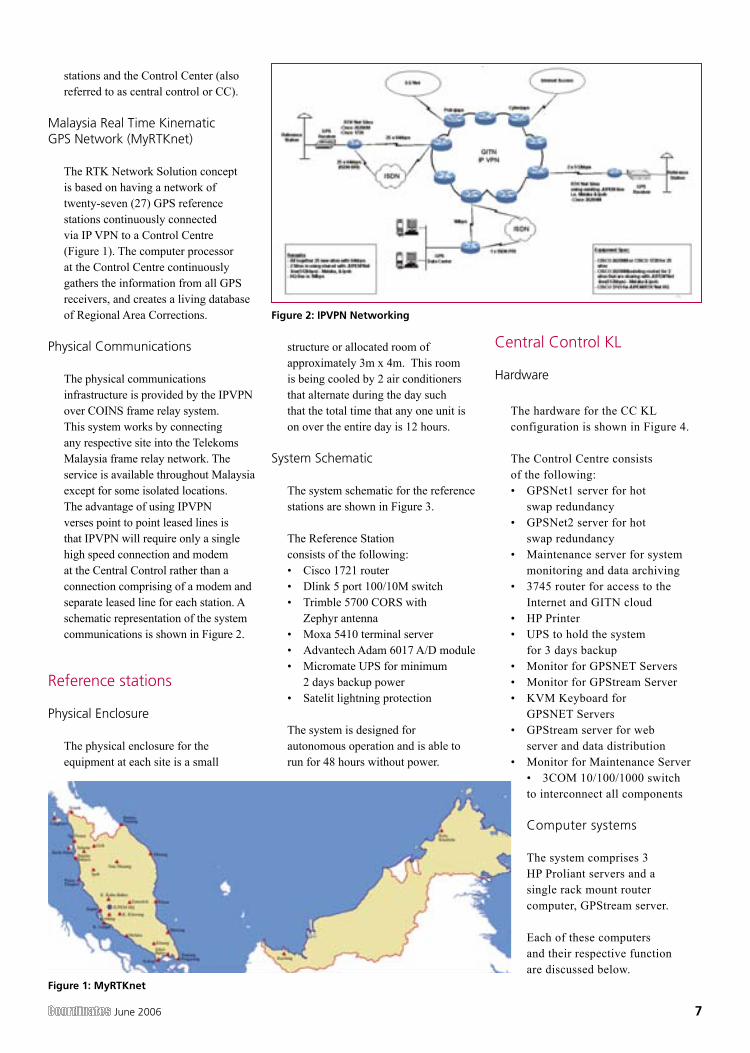
The RTK Network Solution concept is based on having a network of twenty-seven (27) GPS reference stations continuously connected via IP VPN to a Control Centre (Figure 1). The computer processor at the Control Centre continuously gathers the information from all GPS receivers, and creates a living database of Regional Area Corrections.
Physical Communications
The physical communications infrastructure is provided by the IPVPN over COINS frame relay system. This system works by connecting any respective site into the Telekoms Malaysia frame relay network. The service is available throughout Malaysia except for some isolated locations. The advantage of using IPVPN verses point to point leased lines is that IPVPN will require only a single high speed connection and modem at the Central Control rather than a connection comprising of a modem and separate leased line for each station. A schematic representation of the system communications is shown in Figure 2.
Reference stations
Physical Enclosure
The physical enclosure for the equipment at each site is a small
structure or allocated room of approximately 3m x 4m. This room is being cooled by 2 air conditioners that alternate during the day such that the total time that any one unit is on over the entire day is 12 hours.
System Schematic
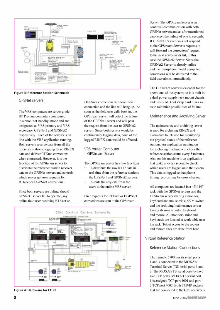
The system schematic for the reference stations are shown in Figure 3.
The Reference Station consists of the following:• Cisco 1721 router• Dlink 5 port 100/10M switch• Trimble 5700 CORS with
Zephyr antenna• Moxa 5410 terminal server• Advantech Adam 6017 A/D module• Micromate UPS for minimum
2 days backup power• Satelit lightning protection
The system is designed for autonomous operation and is able to run for 48 hours without power.
Central Control KL
Hardware
The hardware for the CC KL configuration is shown in Figure 4.
The Control Centre consists of the following:• GPSNet1 server for hot
swap redundancy• GPSNet2 server for hot
swap redundancy• Maintenance server for system
monitoring and data archiving• 3745 router for access to the
Internet and GITN cloud• HP Printer• UPS to hold the system
for 3 days backup• Monitor for GPSNET Servers• Monitor for GPStream Server• KVM Keyboard for
GPSNET Servers• GPStream server for web
server and data distribution• Monitor for Maintenance Server
• 3COM 10/100/1000 switch to interconnect all components
Computer systems
The system comprises 3 HP Proliant servers and a single rack mount router computer, GPStream server.
Each of these computers and their respective function are discussed below.
Figure 1: MyRTKnet
Figure 2: IPVPN Networking
8 June 2006
GPSNet servers
The VRS computers are server grade HP Proliant computers configured in a pure ‘hot standby’ mode and are designated as VRS primary and VRS secondary, GPSNet1 and GPSNet2 respectively. Each of the servers is on line with the VRS application running. Both servers receive data from all the reference stations, logging these RINEX data and deliver RTKnet corrections when connected. However, it is the function of the GPStream server to distribute the reference station receiver data to the GPSNet servers and controls which server get user requests for RTKnet or DGPSnet corrections.
Since both servers are online, should GPSNet1 server fail to operate, any online field user receiving RTKnet or
DGPSnet corrections will lose their connection and the line will hang up. As soon as the field user calls back in, the GPStream server will detect the failure of the GPSNet1 server and will pass the request from the user to GPSNet2 server. Since both servers would be continuously logging data, none of the logged RINEX data would be affected.
VRS router Computer – GPStream Server
The GPStream Server has two functions:• To distribute the raw RT17 data in
real-time from the reference stations the GPSNet1 and GPSNet2 servers.
• To route the requests from the users to the online VRS server.
User requests for RTKnet or DGPSnet corrections are sent to the GPStream
Server. The GPStream Server is in continual communication with both GPSNet servers and as aforementioned, can detect the failure of one in seconds. If GPSNet1 Server does not respond to the GPStream Server’s requests, it will forward the corrections’ request to the next server in its list, in this case the GPSNet2 Server. Since the GPSNet2 Server is already online and the ionospheric model computed, corrections will be delivered to the field user almost immediately.
The GPStream server is essential for the operations of the system; so it is built in a dual power supply rack mount chassis and uses RAID hot swap hard disks so as to minimize possibilities of failure.
Maintenance and Archiving Server
The maintenance and archiving server is used for archiving RINEX and alarm data to CD and for monitoring the physical status of the reference stations. An application running on the archiving machine will check the reference station status every 5 minutes. Also on this machine is an application that make at every second to check which users are logged onto the system. This data is logged so that phone billing records may be cross checked.
All computers are located in a 42U 19” rack with the GPSNet servers and the GPStream server sharing a monitor, keyboard and mouse via a KVM switch and the archiving/maintenance server having its own monitor, keyboard and mouse. All monitors, mice and keyboards are located at work table near the rack. Telnet access to the routers and remote sites are done from here.
Virtual Reference Station
Reference Station Connections
The Trimble 5700 has its serial ports 1 and 3 connected to the MOXA’s Terminal Server (TS) serial ports 1 and 2. The MOXA’s TS serial ports behave like TCP ports. MOXA TS serial port 1 is assigned TCP port 4001 and port 2 TCP port 4002. Both TCP/IP sockets that are connected to the GPS receiver’s
Figure 3: Reference Station Schematic
Figure 4: Hardware for CC KL
June 2006 9
10 June 2006
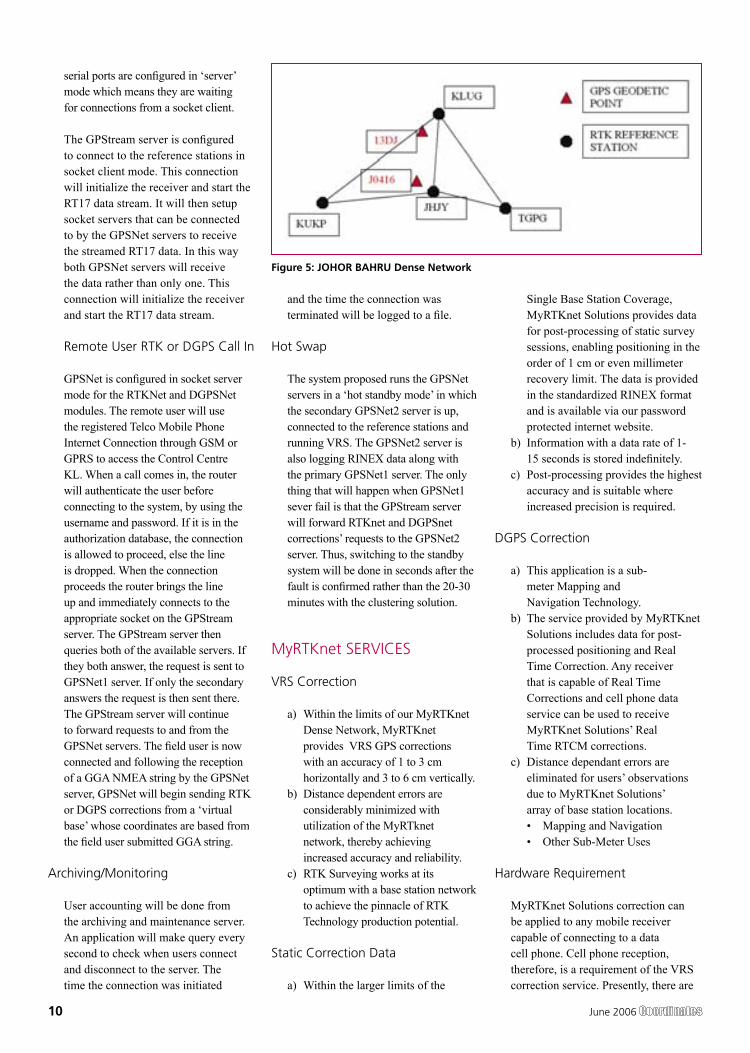
serial ports are configured in ‘server’ mode which means they are waiting for connections from a socket client.
The GPStream server is configured to connect to the reference stations in socket client mode. This connection will initialize the receiver and start the RT17 data stream. It will then setup socket servers that can be connected to by the GPSNet servers to receive the streamed RT17 data. In this way both GPSNet servers will receive the data rather than only one. This connection will initialize the receiver and start the RT17 data stream.
Remote User RTK or DGPS Call In
GPSNet is configured in socket server mode for the RTKNet and DGPSNet modules. The remote user will use the registered Telco Mobile Phone Internet Connection through GSM or GPRS to access the Control Centre KL. When a call comes in, the router will authenticate the user before connecting to the system, by using the username and password. If it is in the authorization database, the connection is allowed to proceed, else the line is dropped. When the connection proceeds the router brings the line up and immediately connects to the appropriate socket on the GPStream server. The GPStream server then queries both of the available servers. If they both answer, the request is sent to GPSNet1 server. If only the secondary answers the request is then sent there. The GPStream server will continue to forward requests to and from the GPSNet servers. The field user is now connected and following the reception of a GGA NMEA string by the GPSNet server, GPSNet will begin sending RTK or DGPS corrections from a ‘virtual base’ whose coordinates are based from the field user submitted GGA string.
Archiving/Monitoring
User accounting will be done from the archiving and maintenance server. An application will make query every second to check when users connect and disconnect to the server. The time the connection was initiated
and the time the connection was terminated will be logged to a file.
Hot Swap
The system proposed runs the GPSNet servers in a ‘hot standby mode’ in which the secondary GPSNet2 server is up, connected to the reference stations and running VRS. The GPSNet2 server is also logging RINEX data along with the primary GPSNet1 server. The only thing that will happen when GPSNet1 sever fail is that the GPStream server will forward RTKnet and DGPSnet corrections’ requests to the GPSNet2 server. Thus, switching to the standby system will be done in seconds after the fault is confirmed rather than the 20-30 minutes with the clustering solution.
MyRTKnet SERVICES
VRS Correction
a) Within the limits of our MyRTKnet Dense Network, MyRTKnet provides VRS GPS corrections with an accuracy of 1 to 3 cm horizontally and 3 to 6 cm vertically.
b) Distance dependent errors are considerably minimized with utilization of the MyRTknet network, thereby achieving increased accuracy and reliability.
c) RTK Surveying works at its optimum with a base station network to achieve the pinnacle of RTK Technology production potential.
Static Correction Data
a) Within the larger limits of the
Single Base Station Coverage, MyRTKnet Solutions provides data for post-processing of static survey sessions, enabling positioning in the order of 1 cm or even millimeter recovery limit. The data is provided in the standardized RINEX format and is available via our password protected internet website.
b) Information with a data rate of 1-15 seconds is stored indefinitely.
c) Post-processing provides the highest accuracy and is suitable where increased precision is required.
DGPS Correction
a) This application is a sub-meter Mapping and Navigation Technology.
b) The service provided by MyRTKnet Solutions includes data for post-processed positioning and Real Time Correction. Any receiver that is capable of Real Time Corrections and cell phone data service can be used to receive MyRTKnet Solutions’ Real Time RTCM corrections.
c) Distance dependant errors are eliminated for users’ observations due to MyRTKnet Solutions’ array of base station locations. • Mapping and Navigation• Other Sub-Meter Uses
Hardware Requirement
MyRTKnet Solutions correction can be applied to any mobile receiver capable of connecting to a data cell phone. Cell phone reception, therefore, is a requirement of the VRS correction service. Presently, there are
Figure 5: JOHOR BAHRU Dense Network
June 2006 11
VRS Correction Test is to compare GPS observed coordinates with their corresponding published GPS geodetic values. The test was carried out at the existing GPS geodetic network in the Dense Network. An example of the layout of the network test site is shown in Figure 5.
b. The Dense Network consists of 3 sites located at Klang Valley, Penang and Johor Bahru. For this case study, Johor Bahru Dense Network was selected .This site comprises of four (4) GPS reference stations (known stations) namely KUKP, JHJY, TGPG and KLUG. The test was carried out using VRS technique with 5 sessions of observation (consisting of 10 measurements in each session) on 2 GPS receivers.
c. Dual frequency GPS receivers were used in the test with the observation
mobile receivers which has both the capabilities of wireless connection to the cell phone and data collector. Any single or dual frequency GPS receiver can be used to collect data and for static correction data application, post-processing software package is needed to reduce the data to final position that uses standard RINEX files.
Possible Field Applications
MyRTKnet services can be used for various surveying applications ranging from setting up of control to the detailing of project sites; its usage will benefit surveyors and many other GPS users who rely on these utilities to locate their positions. The following are some of the possible field applications of MyRTKnet services:• Engineering Survey• Topographic Survey• Boundary Survey• Construction Staking• Utility Extension Survey• Flood Survey Study and Analysis• Photogrammetric Control Surveys• GIS Applications• Control surveys for monumentation• Wetland Location Surveys• Soil Location Survey• Flagging Clearing Limits• Tree Surveys• Mapping and Navigation
MyRTKnet testing
Case study for high accuracy VRS correction test
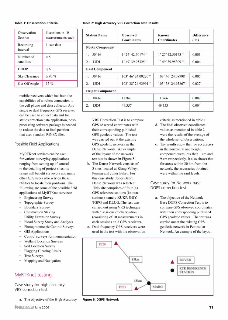
a. The objective of the High Accuracy
criteria as mentioned in table 1.d. The final observed coordinates
values as mentioned in table 2 were the results of the average of the whole set of observations.
e. The results show that the accuracies in the horizontal and height component were less than 1 cm and 9 cm respectively. It also shows that for areas within 30 km from the network, the accuracies obtained were within the said levels.
Case study for Network base DGPS correction test
a. The objective of the Network Base DGPS Correction Test is to compare GPS observed coordinates with their corresponding published GPS geodetic values. The test was carried out at the existing GPS geodetic network in Peninsular Network. An example of the layout
Table 2: High Accuracy VRS Correction Test ResultsTable 1: Observation Criteria
Figure 6: DGPS Network
12 June 2006
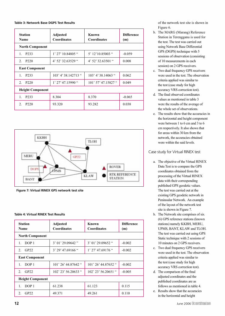
of the network test site is shown in Figure 6.
b. The MARG (Marang) Reference Station in Terengganu is used for the test. The test was carried out using Network Base Differential GPS (DGPS) technique with 5 sessions of observation (consisting of 10 measurements in each session) on 2 GPS receivers.
c. Two dual frequency GPS receivers were used in the test. The observation criteria applied was similar to the test (case study for high accuracy VRS correction test).
d. The final observed coordinates values as mentioned in table 3 were the results of the average of the whole set of observations.
e. The results show that the accuracies in the horizontal and height component were between 1 to 6 cm and 3 to 6 cm respectively. It also shows that for areas within 30 km from the network, the accuracies obtained were within the said levels.
Case study for Virtual RINEX test
a. The objective of the Virtual RINEX Data Test is to compare the GPS coordinates obtained from the processing of the Virtual RINEX data with their corresponding published GPS geodetic values. The test was carried out at the existing GPS geodetic network in Peninsular Network. An example of the layout of the network test site is shown in Figure 7.
b. The Network site comprises of six (6) GPS reference stations (known stations) namely KKBH, MERU, UPMS, BANT, KLAW and TLOH. The test was carried out using GPS Static technique with 2 sessions of 10 minutes on 2 GPS receivers.
c. Two dual frequency GPS receivers were used in the test. The observation criteria applied was similar to the test (case study for high accuracy VRS correction test).
d. The comparison of the final adjusted coordinates and the published coordinates are as follows as mentioned in table 4.
e. Results show that the accuracies in the horizontal and height
Table 3: Network Base DGPS Test Results
Table 4: Virtual RINEX Test Results
Figure 7: Virtual RINEX GPS network test site
June 2006 13
component were between 1 to 2 cm and 10 cm respectively, and that for areas within 30 km from the network, the accuracies obtained were within the said levels.
Conclusion
This paper introduces a new GPS positioning by way of RTK-GPS (VRS) using MyRTKnet services provided by DSMM. MyRTKnet has been successfully implemented with the establishment of a Network of Reference Stations equipped with GPS receiver, antenna, communication server/router, software, power supply, UPS, lightning arrestor and other accessories and equipments necessary for the full working of the station. A Control Centre has also been established - equipped with computation server, software, power supply, UPS, communication router/server, Web server and other
accessories and equipment necessary for the operations of the facility. The precision estimation of positioning results surveyed by VRS has also been verified. Outcome of field experiments shows that standard deviations of 3-components of real-time positioning by VRS are about ±2 cm in horizontal and less than ±4 cm in vertical and this meets the demand for survey precision of local control point. Network DGPS solutions have also been tested with results showing that sub-meter applications were possible in areas where VRS correction are not available.
Dato’ Hamid Ali Director General, Department of Survey and Mapping Malaysia (JUPEM), Malaysia
Ahmad Fauzi Nordin Department of Survey and Mapping Malaysia (JUPEM), Malaysia [email protected]
Dr Samad Hj Abu Department of Survey and Mapping Malaysia (JUPEM), Malaysia
Chang Leng Hua Department of Survey and Mapping Malaysia (JUPEM), Malaysia
14 June 2006
Galileo OS SIS ICD now available on-line
The information contained in the Galileo Open Service Signal In Space Interface Control Document (SIS ICD) is made available to the public by the Galileo Joint Undertaking (GJU), an undertaking jointly created by the European Commission and the European Space Agency. www.galileoju.com
Galileo funding in doubt?
Under the headline ‘EU stumbles over funding for Galileo’, the eupolitix.com website reports that the Galileo satellite navigation project has stalled because of a disagreement over funding. It reports that the development of the project has been delayed after the EU’s industrial partner, the now-single consortium that will build the system under the Concession, complained that the Commission had reneged on its promised investment. The EU budget for 2007-2013 now earmarks E900m for Galileo, although the initial pledge was for E1bn. The EC is due to issue a progress report on funding negotiations soon. www.eupolitix.com
Europe ‘wants Japan to join Galileo’
Europe is still keen on Japan joining the Galileo programme, according to the Japanese press, which reports that the EU and its industry are watching with keen interest to see how Japan - a heavy GPS user - eventually positions itself. ‘Japan would be a very good test market for Galileo because there are many
people using mobile phones and people who like gadgets,’ according to Paul Flament, administrator of the Galileo Programme at the EC. He added that ‘Japan is at the forefront of technology. That’s why we would like to cooperate with Japan - because we know the country is important in the domain’.
Peter Grognard, MD of Septentrio Satellite Navigation NV, currently the sole supplier of Galileo receivers, acknowledges that Japan is ‘years ahead’ of Europe in the adoption of GPS in-car navigation and mobile phones. He commented ‘I think Japan will be an excellent and early adopter of Galileo, just like it has been with GPS’. A EU delegation to Japan in December 2003, seeking their participation in the Galileo programme, was given the cold shoulder. http://mdn.mainichi-msn.co.jp
LogicaCMG to develop key security features for Galileo programme
LogicaCMG announced that it has been selected for three important development contracts valued at over 20 million Euros (about £14 million) in Europe’s Galileo programme. The three contracts are to develop the facilities that manage the most security sensitive elements of the programme - the Public Regulated Service Key Management Facility (PKMF), the Mission Key Management Facility (MKMF) and the Ground Control Segment Key Management Facility (GCS-KMF). www.logicacmg.com
Galileo updateGalileo – the European Programme for Global Navigation Services for civil purposes is an initiative led by European Union. We provide regular updates to our readers on the Galileo programme.
NEWSBRIEF - GIS
Indonesian military plane to map quake-hit areas
The Indonesian Defence Forces (TNI) have assigned a CN-235 airplane to carry out aerial photography on areas in the Yogyakarta region affected by 27 May 5.9-magnitude earthquake. The activity is aimed at making a detailed map of areas devastated by the quake.
TNI had also sent a Hercules C-130 plane carrying a TNI field medical team and three helicopters to evacuate victims. http://news.xinhuanet.com
Hong-Kong to implement GIS for population by-census
The 2006 population by-census in Hong Kong will be held in July and August, and 5,000 temporary field workers will be recruited for data collection, the Census & Statistics Department said. The Commissioner for Census & Statistics Fung Hing-wang said the department will use the GIS to support the field operation, and let respondents furnish online data, and adopt Intelligent Character Recognition technology, to enhance the efficiency of data capturing. www.news.gov.hk
India, Pakistan agree to conduct joint survey of Sir Creek
India and Pakistan agreed to conduct a joint survey of the Sir Creek area - a marshy area in Rann of Kutch between Gujarat and Sindh province of Pakistan, as they winded up official-level talks in New Delhi. The survey will be conducted both in creek and sea soon and the technical experts of the two countries will work out modalities, officials said. www.hindu.com
Google puts street data in map of Australia
Google overnight sneaked out street mapping data for Australia and New Zealand cities within Google Maps. Google Maps offers businesses a means of overlaying their own data or statistics over detailed street maps on their web site. http://news.google.com
June 2006 15
16 June 2006
NEWSBRIEF - INDUSTRY
Product
RT-5SW new long-range laser
A new long-range, dual-slope laser ideally suited for large job sites and agricultural land-leveling has been announced by Topcon Positioning Systems. The RT-5SW retains all of the primary benefits of the RT-5S series including five-arc-second accuracy - less than 1/32nd of an inch per 100 feet. It also features an integrated radio remote controller capable of two-way communication up to 1,000 feet. Radio communications between the remote and the base laser allows the operator to verify adjustments right from the cab of a machine. www.topconpositioning.com
BAE Systems launches Version 5.3 of SOCET SET
BAE Systems announced the release of SOCET SET v5.3. This new release provides additional sensor models and new features based on automatic tie-point measurement for multi-sensor triangulation. Productivity improvements have been made throughout the SOCET SET workflow, including enhancements to SOCET for ArcGIS, Sketch, Feature Extraction, Mosaic and more. Automatic Terrain Extraction (ATE) has been improved with enhancements for bare-earth and reflected surface processing using back-matching and multi-pair matching. www.socetset.com
Leica Geosystems launches Leica fieldPro
Leica fieldPro, a mobile CAD software, is the on-site and on-demand field solution for Surveying, Architecture, Engineering and Construction (AEC).
fieldPro works seamlessly together with Leica Geosystems sensors, such as TPS, GPS and Leica DISTO plus, allowing users to create and visualize 2D drawings or 3D CAD models of any site in real time. With Leica fieldPro all tasks can be completed on site with no site revisits or rework. Office work is significantly reduced and productivity improved.
Leica Geosystems has also announced the introduction of Leica ScanStation, the first 3D laser scanner with four “core” total station features, offering easier operation, increased field & office productivity, and greater flexibility for as-built and topographical surveys. www.leica-geosystems.com
Blue Marble Geographics’ GeoObjects® 4.1
Blue Marble Geographics announces the release of GeoObjects® 4.1, a leading map display tool kit for GIS developers. Blue Marble, known for their coordinate conversion technology, is also the creator of industry leading map display, image reprojection, referencing, and map file translation technology. www.bluemarblegeo.com
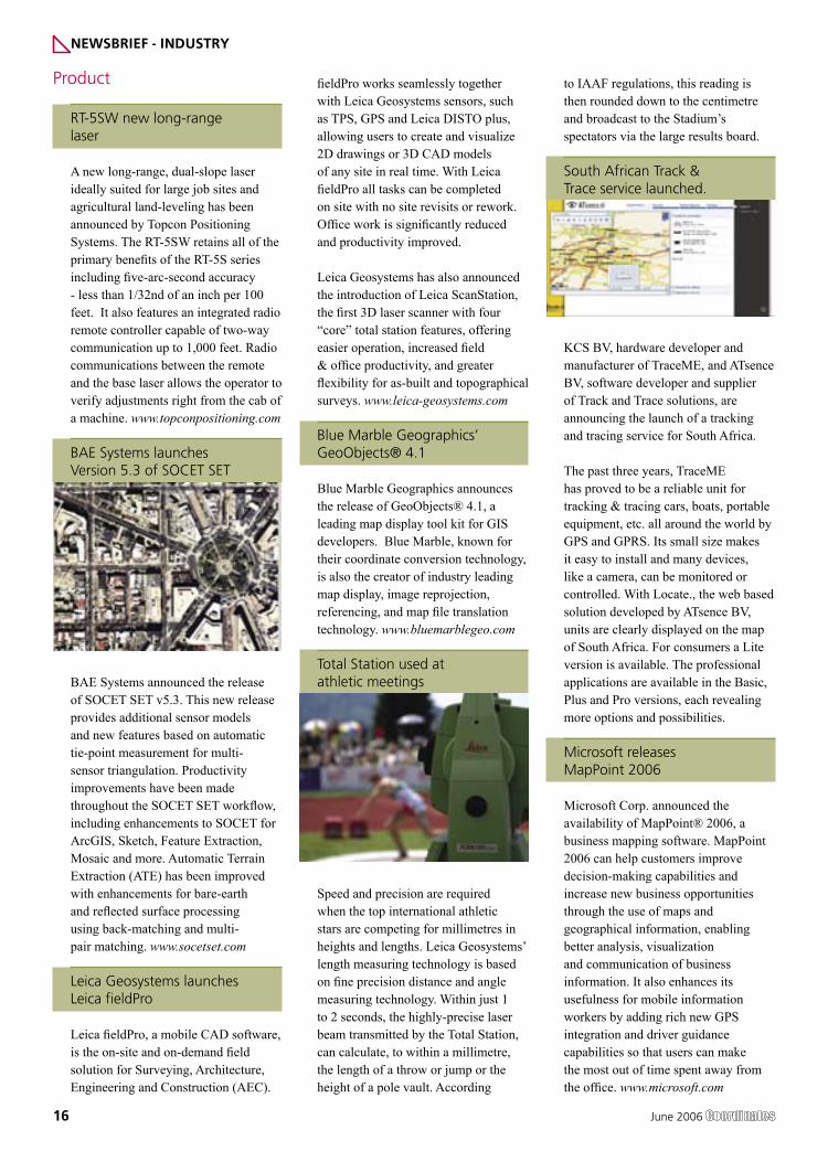
Total Station used at athletic meetings
Speed and precision are required when the top international athletic stars are competing for millimetres in heights and lengths. Leica Geosystems’ length measuring technology is based on fine precision distance and angle measuring technology. Within just 1 to 2 seconds, the highly-precise laser beam transmitted by the Total Station, can calculate, to within a millimetre, the length of a throw or jump or the height of a pole vault. According
to IAAF regulations, this reading is then rounded down to the centimetre and broadcast to the Stadium’s spectators via the large results board.
South African Track & Trace service launched.
KCS BV, hardware developer and manufacturer of TraceME, and ATsence BV, software developer and supplier of Track and Trace solutions, are announcing the launch of a tracking and tracing service for South Africa.
The past three years, TraceME has proved to be a reliable unit for tracking & tracing cars, boats, portable equipment, etc. all around the world by GPS and GPRS. Its small size makes it easy to install and many devices, like a camera, can be monitored or controlled. With Locate., the web based solution developed by ATsence BV, units are clearly displayed on the map of South Africa. For consumers a Lite version is available. The professional applications are available in the Basic, Plus and Pro versions, each revealing more options and possibilities.
Microsoft releases MapPoint 2006
Microsoft Corp. announced the availability of MapPoint® 2006, a business mapping software. MapPoint 2006 can help customers improve decision-making capabilities and increase new business opportunities through the use of maps and geographical information, enabling better analysis, visualization and communication of business information. It also enhances its usefulness for mobile information workers by adding rich new GPS integration and driver guidance capabilities so that users can make the most out of time spent away from the office. www.microsoft.com
June 2006 17
u-blox launches AssistNowT A-GPS Service Framework
u-blox AG, a leading GPS technology and solution provider has AssistNowT, a complete Assisted GPS (“A-GPS”) service package that brings instant positioning to any u-blox GPS-enabled device with mobile phone connectivity. The new technology cuts a GPS receiver’s Time To First Fix (“TTFF”) to seconds by providing the receiver with assistance data that practically eliminates download times of data originating from the satellites. www.u-blox.com
Business
Trimble opens office in India
Trimble is strengthening its local commitment by opening an office in India to better meet the needs of the region. Trimble Navigation India Pvt Ltd., located in Gurgaon, will be the primary base for sales and support of all survey and construction as well as mapping and GIS solutions for the country. “The opening of the Gurgaon office is an important extension of our presence in India and the Asia Pacific region,” said Christian Knoll, Trimble’s Engineering & Construction regional sales manager for India. “We see this as an opportunity to better service our customers to assist in the modernization drive taking place.” www.trimble.com
Personal navigation solution to reach 12 million by 2009
A new research report from the analysis firm Berg Insight forecasts that shipments of handset based personal
navigation solutions in Europe and the US will reach 12 million units by 2009. The year 2005 marked the first successful marriage of cellular and navigation technologies, resulting in shipments of around 1 million on-board and off-board systems, mainly in the fourth quarter. Supported by the phenomenal growth recorded in the PND segment, handset based personal navigation solutions are expected to grow by 86 percent year-on-year. [email protected]
Geospatial market in India to touch USD 613 million
Growth in the use of spatial technologies based on maps and satellite imageries has secured acceptance for geospatial technology in India as an effective decision-making tool. Many government agencies have now realised that this technology can provide them the much-needed tool to address the ever increasing demand for data availability. The figures for 2005 is Rs 10 crore (USD 2.1 million) while it will touch Rs 53 crore (USD 11.5 million) by 2010. www.business-standard.com
Trimble equips Polish Government Agency with GPS
Trimble announced that it has supplied 271 GeoXT™ rugged GPS handheld receivers, part of the GeoExplorer® series, to Poland’s Plant Health and Seed Inspection Services (PHSIS), a national government agency. This purchase follows an earlier sale of 156 GeoExplorer units to Poland’s agency for Restructuring and Modernization of Agriculture in early 2005. www.trimble.com
MapInfo introduces new location intelligence application for IBM
MapInfo Corporation announced that IBM has selected MapInfo technology to power the new Prospecting portlet in IBM’s Core Life Solution for the insurance industry. The MapInfo Prospecting portlet enables insurance agents to identify and locate target
customers based on neighbourhood demographic, lifestyle and consumption patterns, helping increase sales and market share. www.mapinfo.com
CSI Wireless Q1 Revenues Increase 59%
CSI Wireless Inc., a designer and manufacturer of advanced GPS products, reported a 59% increase in revenues for the first quarter ended March 31, 2006, as Hemisphere GPS revenue reached $15.5 million. As a result of selling its Fixed Wireless Telephone business, CSI recorded an impairment in its goodwill totaling $8 million, resulting in a net loss of $9.2 million, or ($0.20) per share for the first quarter. www.csi-wireless.com
PCI Geomatics partners with TGIS Technologies
Geomatics has announced the signing of a strategic distributor partnership with TGIS Technologies Inc. The agreement will allow PCI Geomatics to market, distribute, and sell the TGIS real-time GeoConference™ Software. TGIS Technologies built GeoConference to allow users to hold Internet teleconferences based on multi-source geospatial information. This unique solution allows groups to capture, preserve, and reuse geographic information, track and coordinate resources and interventions, and transmit geospatial data in real-time.
Lockheed Martin and EADS Astrium to team on future GNSS
Lockheed Martin and EADS Astrium announced that they have signed a teaming agreement to ensure interoperability of the GPS III and the European Galileo Satellite Navigation programmes – the world’s two most important upcoming satellite navigation systems. The companies intend to perform systems engineering and technical assistance tasks for each other in the areas of interoperability, integrity and optimisation of joint constellation performance. www.lockheedmartin.com
18 June 2006
NEWSBRIEF - GPS
China to survey the Great Wall
The Great Wall resource investigation has kicked off officially in Hebei Province. It is the first time for China to make precise measurement and accurate survey on the Great Wall with comprehensive investigation and mapping skills, which will be undertaken for several years.
China has launched the nationwide investigation of the Great Wall for twice since the establishment of the new China. In the mid-1950s, China did primary investigation on the age and distribution of the Great Wall with the help of the national cultural relic survey, and the second-time investigation was undertaken in the 1980s. http://news.xinhuanet.com
US policy shift pushes back plans for new GPS satellites
Long-pending Pentagon plans to solicit bids for a new generation of significantly enhanced, more-powerful GPS have been delayed at least a year, partly due to Air Force policy changes that stress less-risky, incremental acquisition of new space hardware, according to military and industry officials. On the drawing boards since the late 1990s and previously projected to be put out for bid this year, the so-called GPS III programme remains in limbo as Air Force and Pentagon brass mull its design and timing. http://online.wsj.com
Telcordia turns Ford Car into wireless communication center
In collaboration with Ford Motor Company, Telcordia revealed a completely wireless-enabled Ford Five Hundred sedan. This latest development from Telcordia’s world-renown Advanced Technology organization demonstrates Telcordia’s innovative approach to leveraging technology and capitalizing on new market opportunities as the lines between some of the consumer’s most treasured assets -- cars and communications -- blur. www.telcordia.com
NEWSBRIEF - LBS
Navigate with Garmin StreetPilot 2820
Garmin International Inchas announced the StreetPilot 2820, a premium automotive and motorcycle navigation device for customers, as well as a configurable platform for Garmin’s growing list of OEM partners. The StreetPilot 2820 builds upon the success of the StreetPilot 2700 series, and also incorporates Bluetooth wireless connectivity and a hands-free calling interface. www.garmin.com
Tele Atlas’ voice enabled maps
Tele Atlas has announced that its phonetic data is now integrated in the newly-available Pioneer AVIC Z1 model in-car navigation and TomTom 910 portable navigation systems. Tele Atlas’ phonetic data increases the quality of speech technology used in map-based applications by providing more precise pronunciations of location and directional information.
The phonetic data, critical in hands-free environments and created by Tele Atlas’ own team of linguists, is the most complete available. It includes street and sign name data, administrative information for country, state, county, city and municipality levels, and points of interest in a range of pronunciations covering more than 10 European and North American languages. www.teleatlas.com
Telcontar adds China map data
Telcontar, the supplier of software platforms and services for the location-based services (LBS) market, announced the launch of its Drill Down Server (DDS) 4.1. The newest version of the LBS industry’s most widely deployed geospatial software platform adds China map data and a host of customized performance enhancements that enable Telcontar customers to deploy dynamic location-enhanced applications that meet the region-specific needs of China’s burgeoning market. www.telcontar.com
Stockholm subway implements indoor LBS platform
Cisco Systems has announced a collaboration with software provider Appear Networks to deliver an Integrated Location Services Solution for the Stockholm Subway, delivering personalised, real-time information to users in underground stations, anywhere across the Wi-Fi network.
Based on contextual information such as time of day, job role, and current physical location, the solution is able to access the right information, which is interpreted and pushed out in real time to the right users, and to the right location. http://newsroom.cisco.com
Scottish City to pioneer personalized wireless information
Dundee moved a step closer to becoming Scotland’s city of wireless innovation, with the announcement of a partnership between the University of Abertay Dundee and LastMile Communications, the British company pioneering a wireless delivery platform using WiFi. Under the agreement, the Abertay campus will become a test bed for LastMile’s state-of-the-art node-based wireless information system. The technology offers end user-focused content to mobile devices on demand, and tailored precisely to their location. www.lastmilecoms.com
Mapping software to power Locator Web Product
ESRI has announced that Xionetic Technologies has selected ESRI’s RouteMAP IMS software to power its new store locator service. Xionetic is using RouteMAP IMS to create Locator Web, a Web-based hosting solution that allows companies including Kohler, North Face and Sketchers to easily add a dealer or store locator and mapping and driving direction functionality to their Web sites without hosting the services themselves. Xionetic hosts more than 170 customers’ sites and plans to use RouteMAP IMS to rapidly grow this in the coming months. www.esri.com

June 2006 19
20 June 2006
1. Background
The Central Government announced the National Map Policy (NMP) on 19th May 2005. The NMP document authorizes Survey of India (SOI) to issue detailed guidelines on the implementation of the NMP. These guidelines are issued in the light of the above cited authorization. The guidelines are clarificatory in nature and does not create any new rights nor abridge any existing rights which are enforceable in courts of law.
2. Information on Maps and guidance of indentors
a) All up-to-date information on SOI maps shall be available at the various offices, map sales counters and Geospatial Data Centres (GDC) under the SOI. The information shall also be available on Survey of
India website www.surveyofindia.gov.in created and maintained by the SOI. The information provided inter alia includes all relevant details of maps such as scale, information content, date of data capture, price, mode of data dissemination whether MOD clearance available for issue as Open Series Map (OSM) etc. The website also has a search engine by which the exact sheet number of a given locality can be traced by giving elementary details like name of district or any other prominent feature. SOI offices may be contacted for further information on OSMs.
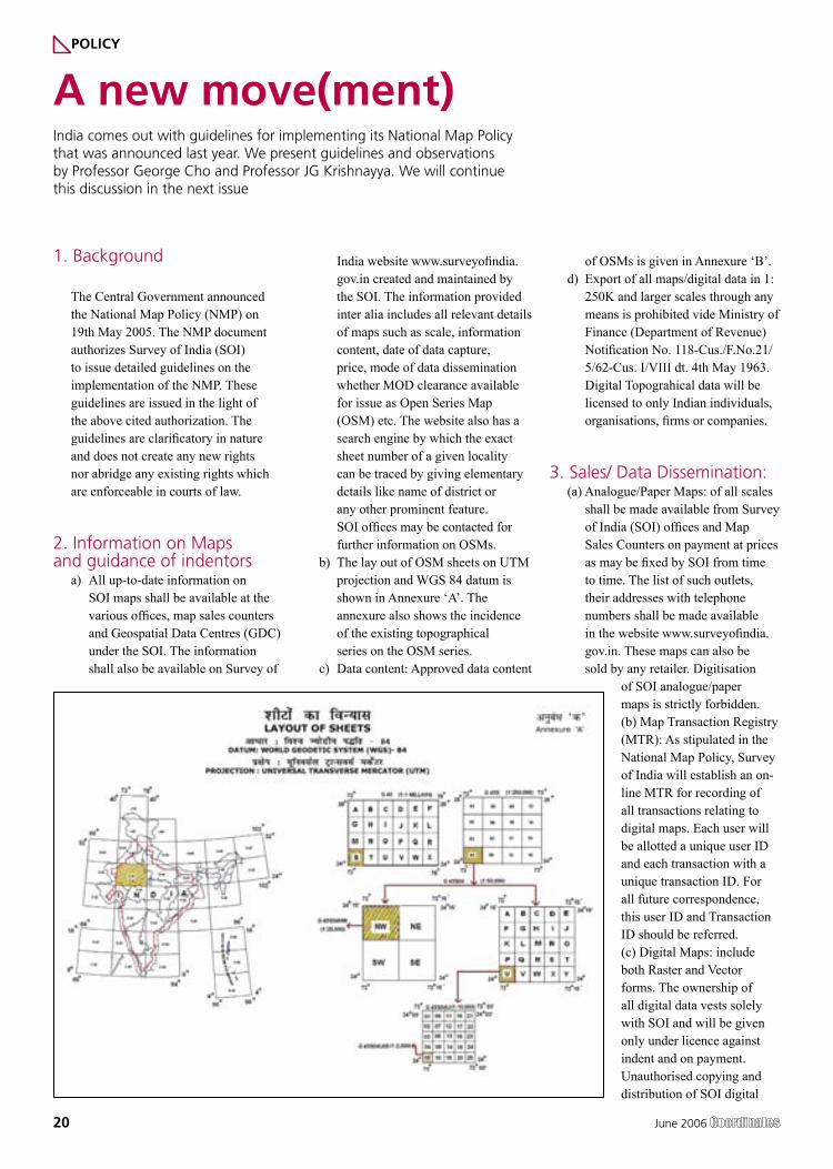
b) The lay out of OSM sheets on UTM projection and WGS 84 datum is
shown in Annexure ‘A’. The annexure also shows the incidence of the existing topographical series on the OSM series.
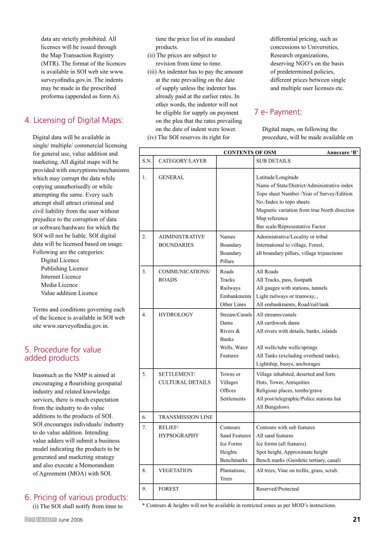
c) Data content: Approved data content
of OSMs is given in Annexure ‘B’.d) Export of all maps/digital data in 1:
250K and larger scales through any means is prohibited vide Ministry of Finance (Department of Revenue) Notification No. 118-Cus./F.No.21/ 5/62-Cus. I/VIII dt. 4th May 1963. Digital Topograhical data will be licensed to only Indian individuals, organisations, firms or companies.
3. Sales/ Data Dissemination:(a) Analogue/Paper Maps: of all scales
shall be made available from Survey of India (SOI) offices and Map Sales Counters on payment at prices as may be fixed by SOI from time to time. The list of such outlets, their addresses with telephone numbers shall be made available in the website www.surveyofindia.gov.in. These maps can also be sold by any retailer. Digitisation
of SOI analogue/paper maps is strictly forbidden.(b) Map Transaction Registry (MTR): As stipulated in the National Map Policy, Survey of India will establish an on-line MTR for recording of all transactions relating to digital maps. Each user will be allotted a unique user ID and each transaction with a unique transaction ID. For all future correspondence, this user ID and Transaction ID should be referred.(c) Digital Maps: include both Raster and Vector forms. The ownership of all digital data vests solely with SOI and will be given only under licence against indent and on payment. Unauthorised copying and distribution of SOI digital
A new move(ment)India comes out with guidelines for implementing its National Map Policy that was announced last year. We present guidelines and observations by Professor George Cho and Professor JG Krishnayya. We will continue this discussion in the next issue
POLICY
June 2006 21
data are strictly prohibited. All licenses will be issued through the Map Transaction Registry (MTR). The format of the licences is available in SOI web site www.surveyofindia.gov.in. The indents may be made in the prescribed proforma (appended as form A).
4. Licensing of Digital Maps:
Digital data will be available in single/ multiple/ commercial licensing for general use, value addition and marketing. All digital maps will be provided with encryptions/mechanisms which may corrupt the data while copying unauthorisedly or while attempting the same. Every such attempt shall attract criminal and civil liability from the user without prejudice to the corruption of data or software/hardware for which the SOI will not be liable. SOI digital data will be licensed based on usage. Following are the categories:
Digital Licence Publishing LicenceInternet LicenceMedia LicenceValue addition Licence
Terms and conditions governing each of the licence is available in SOI web site www.surveyofindia.gov.in.
5. Procedure for value added products
Inasmuch as the NMP is aimed at encouraging a flourishing geospatial industry and related knowledge services, there is much expectation from the industry to do value additions to the products of SOI. SOI encourages individuals/ industry to do value addition. Intending value adders will submit a business model indicating the products to be generated and marketing strategy and also execute a Memorandum of Agreement (MOA) with SOI.
6. Pricing of various products:(i) The SOI shall notify from time to
time the price list of its standard products.(ii) The prices are subject to
revision from time to time.(iii) An indentor has to pay the amount
at the rate prevailing on the date of supply unless the indenter has already paid at the earlier rates. In other words, the indenter will not be eligible for supply on payment on the plea that the rates prevailing on the date of indent were lower.
(iv) The SOI reserves its right for
differential pricing, such as concessions to Universities, Research organizations, deserving NGO’s on the basis of predetermined policies, different prices between single and multiple user licenses etc.
7 e- Payment:
Digital maps, on following the procedure, will be made available on
22 June 2006
MTR sounds to be too rigid
Prof J G Kri hnayya Director, Systems Research Institute, Pune, India [email protected]
It is good that SoI has been quick to release a comprehensive statement on the manner in which digital maps will be made available to the Indian mapping community.
I assume that these Guidelines will be modified as the real-world experience suggests where changes will improve communication, increase speed, simplify operations. This kind of openness to the possibility of change is always needed.
Committing the SoI to have available all information at all SoI offices, and on the website is a good thing.
Committing the SoI to UTM and WGS-84 - international standards - is also really a great improvement.
Data Content
Here is where one has to raise questions again about the elimination of all height information from OSM maps. We would appeal again to the SoI and the MoD that they consider the purposes for which digital maps are needed and are to be used in India.
For the foreseeable future, the most important geographic problem facing the country is (a) Urban expansion and (b) Global Warming and related problems, including water availability. Of the two (b) is more serious, although (a) is more urgent. Particularly where we are tracking snow-melt, and snow-pack, height information is very very important. As water becomes ever more a valuable resource, flow information, flow possibilities and therefore height information becomes more and more important. It is very obvious to any urban planner that
height information in and around settlements is essential for rational planning. For these - and many other - reasons, we would appeal to the MoD to relax their veto of height information. The international strategic situation, the types of conflicts that India is likely to be in, also suggest that 1-5-10 meter contours will not be important for our defence at a time when satellite-derived information is freely available to potential enemies.
MTR
The concept of the Map Transaction Register which enables IT-based total control over the distribution of maps, sounds to me to be too rigid for the culture of the Indian subcontinent. India and Indians do not have the discipline in our culture to sustain such a well-defined methodology (and I say that without criticising our undisciplined, untrammelled style of living). (I note, by the way, that the Guidelines apparently make it illegal for any body, individual or corporate, who is not “Indian” to indent for or to posses an SoI digital map.) It is not clear to me whether this is entirely realistic.
Pricing
The idea of concessional pricing for NGOs, for Educational institutions, for Research is a good idea, as is the separation of Single-copy, Value-added, Commercial, etc. “markets” - and therefore licensing regimes for maps.
However, I wonder whether everyone who would like to make amendations to SoI maps before using/reselling them in a niche market would be able to create a business plan on the basis of which an MoA could be drawn up. This would tend to restrict access to maps to larger organisations, I fear. This approach seems to be patterned on that of The Ordnance Survey (UK), where the situation is quite different from India’s, so that I feel such a practise could well be held up for a decade or so until the Indian digitil-map-market has matured more.
variety of media like Compact Disks (CDs), DVD etc. Maps on 1:1M and smaller scale on compressed JPEG format will be available for download against online submission of licence agreement and on e-payment. The self-guide provided in www.surveyofindia.gov.in shall enable an indentor to make e-payment and download the requisite maps.
8. Settlement of Disputes:
In case any dispute arises on the applicability or interpretation of these guidelines between the SOI and any other person, the matter shall be referred to the Secretary, Department of Science & Technology, Government of India, whose decision shall be binding on both the parties.
9. Applicability of previous instructions:
The Ministry of Defence has from time to time issued detailed guidelines on various aspects of map access and use. These instructions shall continue to hold good but for the modifications cited in the NMP.
10. General:(i) Copyrights of all SOI maps
(both digital and analogue) vest exclusively with the SOI. Any person resorting to unauthorized copying or use or attempts to do so shall make him liable to criminal and civil liability under existing laws.
(ii) While every effort will be made to ensure availability of maps of all areas containing all necessary details and with highest accuracy, SOI will not be responsible for any loss caused to any person on account of failure on any of the above factors or any other reason.
(iii) The SOI reserves the right to add, delete, modify amend any or all of these guidelines without notice and without assigning any reason.
Send your comments on national map policy at
June 2006 23
Glacial progress
Prof George Cho University of Canberra, Australia [email protected]
The Guidelines are part of the National Map Policy (NMP) announced nearly a year ago (www.surveyofindia.gov.in). This policy authorises the Survey of India (SOI) to issue guidelines for the implementation of the NMP and in particular the use of SOI products – analogue and digital. This commentary makes reference to the paragraphs in the Guidelines. The Guidelines consist of four short unpaginated pages, two annexes and a Digital Products Indent Form.
Paragraph 1 provides the background to the NMP at 19th of May 2005 and the origins of the Guidelines.
In para 2(a) it is mentioned that up-to-date information on SOI maps will be available everywhere SOI products are handled. A web site address is given for Internet transactions.
Export
More significantly para 2(c ) pertains to approved data content of all Open Series Maps. Further details are outlined in Annex ‘B’. However, mention is made that “export of all maps/digital data in 1:250K and larger scales through any means is prohibited”. Users might ask the question of the meaning of “export”. Any local company may export derived products, albeit, based on SOI information; would this be permissible?
Licence
The next sentence states that “topographical data will be licensed to only Indian individuals, organisations, firms or companies”. The meaning of licence is not defined. Is this a licence to use, a licence to copy, a licence to re-purpose? Further only Indian individuals may be licensed. It is unclear whether this includes those with dual citizenships,
Indians but non-citizens, and Indians (presumably citizens).
Digitigation
On para 3 the heading on Sales/Data Dissemination contains three sub-sections. In particular sub-para (a) prohibits the “digitisation of SOI analogue/paper maps”. The Guidelines do not state whether these are in raster or vector form and is silent about whether scanning the whole map sheet as one image is permissible.
MTR
Para 3(b) refers to a map transaction registry (MTR) presumably a record of all sales and licensing transactions undertaken. Users will gain a user ID and a transaction ID – presumably for future use and tracing.
Copying
Para 3 (c) states that digital maps include both raster and vector forms. The claim to ownership by SOI is made here on all digital data and will only be given under licence against indent and payment. This appears reasonable. But then the Guidelines goes on to state that “unauthorised copying and distribution of SOI digital data are strictly prohibited”. It is unclear what this copying means because once an agency is licensed by SOI it should be able to make copies within limits of the license. How, for instance, could a company operate if it cannot copy its data for its subsidiary or branches. This statement also begs the question as to whether authorised copying is permissible. Everything seemingly will hinge on the words and terms of the licence that has been provided by SOI.
Formats of licence
In this paragraph the Guidelines discuss the format of the licences and point to its availability on the SOI website. The SOI website provides four main types of licences – media, publishing, digital and Internet. Each of these are pdf documents and are quite comprehensive. Among others, the licences in general deal with the scope and terms of the licence agreements (in terms of definition, licence, licensee’s obligations); SOI
liabilities, Intellectual Property Rights (IPR), Annual licence fee, Changes to the licence, Audit and inspection rights, Transferring rights and responsibilities, Arbitration, Relationships, Force majeure, Termination, Non-Waiver, Governing law and Jurisdiction.
Licensing of Digital Maps
Para 4 deals with Licensing of Digital Maps. While the licensing of the digital data provide for general use, value adding and marketing, there is a statement which warns that encryption technology has been incorporated into the digital products. The original data will be destroyed if the data were subject to copying activities. Criminal and civil liability attach to these unauthorised activities. The issue here is therefore how any company can make use of the data in order to value add to it or use it for marketing purposes without being given the decryption key to unlock the data. This makes the task of re-use, re-purposing the digital data extremely cumbersome and difficult – which presumably is the object of the policy. No details are given as to which parts of the criminal code or civil law would swing into play once someone is detected infringing the agreement.
The format for the “value addition” [sic] licence is not given on the SOI website.
In presentation terms it is believed that it may be better placed to have the various licenses given here as annexes rather than having users refer to the SOI website. Doing so would ease the task of adopting its use more readily.
Value added products
Para 5 deals with Procedure for Value added products. This paragraph contains a good suggestion in the sense of attempting to encourage the geospatial industry and related knowledge services (as well as the location based service industries). The requirement that a business case be mounted under a memorandum of understanding is something new. This innovative requirement should be applauded and should be welcomed by companies using SOI. The key to success in growing
24 June 2006
NEWSBRIEF - REMOTE SENSING
Indian Regional Navigation Satellite System approved
The Union Cabinet of India gave its approval to undertake the development and deployment of an Indian Regional Navigation Satellite System (IRNSS) at a cost of Rs. 1420 crores (USD 312 million), with a foreign exchange component of Rs. 1100.00 crores (USD 246 million) excluding launch services. IRNSS will provide an independent, indigenously developed constellation of satellites to provide satellite-based position, navigation and timing service for critical national applications. http://pib.nic.in
Indian Air Force says Google satellite images not a threat
The satellite images of the country’s defence installation displayed on the Google Earth website do not pose a threat to the Indian Air Force, the Air Chief Marshal S P Tyagi said. “Google is not a threat to the IAF. Showing defence establishments is not a big deal. I can also see others’ (security
set-up using the same technology). We live in a transparent world,” he told reporters. Google Earth had began displaying the images only recently “but I have been seeing them for the last 20 years”, Tyagi said. http://timesofindia.indiatimes.com
China to launch satellites for lunar surveying
China will launch high-resolution satellites to conduct surveying and mapping of the moon in upcoming five years, the People’s Daily reported. The satellites will probe the moon’s surface, physiognomy, landform and geological structure to draw a three-dimensional map of high precision, the report says. http://news.xinhuanet.com
World fire maps now available online in near real time
For a decade now, ESA (European Space Agency) satellites have been continuously surveying fires burning across the Earth’s surface. Worldwide fire maps based on this data are
now available to users online in near-real time through ESA’s ATSR World Fire Atlas. The ATSR World Fire Atlas (WFA) – the first multi-year global fire atlas ever developed – provides data approximately six hours after acquisition and represents an important scientific resource because fire is a major agent of environmental change www.esa.int
Commercial Remote Sensing satellite market in US stabilizing
In a new study, “The Market for Civil & Commercial Remote Sensing Satellites,” Forecast International is projecting deliveries of approximately 139 imaging satellites worth $16.3 billion over the next 10 years. The first half of the period will be more active than the second, with 97 spacecraft slated for production within the next five years. Despite the ever-growing list of remote sensing spacecraft destined for orbit during the next 10 years, very few new players are expected to enter the commercial operator market. www.spacedaily.com
the geospatial industry is one of a partnership rather than a structured hierarchical one of giver and taker.
Pricing
Para 6 spells out the pricing scheme of various products while para 7 gives details on e-Payments. Again this is a good initiative but could be open to abuse in several ways, for instance, non-citizens hiding behind nom-de-guerre in credit cards issued by Indian financial institutions.
Settlement of disputes
Para 8 is about the settlement of disputes while para 9 is about the applicability of previous instructions. The final para 10 is about “copyrights of all SOI maps”. In reality, this should refer to the more generic intellectual property right. There appears to be a gender bias where a statement begins with “any person” and concludes with
“shall make him liable to” criminal and civil liability. Whilst there is a disclaimer in sub-para (ii) (which strictly to be pedantic should be alphabetized rather than numbered) it does not state to what accuracy standards the details are compared with and whether such a disclaimer on possible loss is sufficiently water-tight against possible litigation.
Annex A gives the layout of the sheets under the SOI system of mapping. Annex B gives the contents of the open series maps. These look like the beginnings of metadata headers for digital files of geospatial information. But on closer inspection, the content are of insufficient detail for more universal use or for international comparability.
Data content
Form A is the SOI Digital Products Indent Form – a 3-paged form for use if one wishes to purchase or get
a licence for SOI products. However, such a form lacks a warning on possible civil and criminal liability for entering false information and there is no disclaimer here about the accuracy of maps supplied and the limitation of liability from action for loss or damage incurred as a result of its use.
Overall, an interesting development but reflects the glacial progress into the digital age of a heavy bureaucracy as well as the reality of the information technology revolution in changing the nature of maps in general. however, these Guidelines compare well with the more generic ones in use by Geosciences Australia and Australian government policies Geosciences Australia Digital data licensing and sales policy at http://www.ga.gov.au/nmd/products/purchasing/licencing.htm; and Australian government spatial data policies and guidelines at http://www.osdm.gov.au/osdm/policy.html).

June 2006 25
Christian Knoll, Country Manager Trimble Navigation India Pvt Ltd., prior to this he was posted at the Trimble
European Headquarters in Frankfurt from 2002 – 2006, responsible for European OEM Sales.
He graduated from University in Munich, Germany, with a Degree in Mechanical Engineering and Business Administration.
He received further Management Education from IIM-Ahmedabad and has successfully launched MNC’s in India before joining Trimble. [email protected]
Tell us about Trimble India
Trimble Navigation India Pvt Ltd is a 100% subsidiary of Trimble Navigation Ltd, USA. The India office was established at the end of 2005 and was officially opened on 16, May 2006. It is an important extension of Trimble’s presence in India and the Asia Pacific region. Our objective is to better service our customers and distribution network to assist in the modernization drive taking place in the country.
What is the focus of Trimble’s Engineering & Construction Group?
Trimble’s Engineering and Construction Group focuses on the development of technology and solutions in the core areas of surveying, construction and network infrastructure. We offer integrated positioning solutions and systems that are used from concept to completion to streamline jobs and improve productivity.
What factors do you keep in mind when launching a product?
We listen to our end users, so that we can develop solutions that fit their needs. With this in mind, Trimble creates products that are designed to be accurate and easy-to-use. Each new product also works seamlessly with other Trimble products, so that our customers can employ our complete Integrated Surveying solution to improve productivity on the job site.
Additionally, when launching new products, Trimble is committed to educating and training our distributors and end users, to ensure that end
user benefits and correct operation are maximized. The positive feedback we receive after each event indicates that this method of product introduction is extremely well received by all involved.
How is Trimble different?
Trimble offers complete solutions for the Engineering and Construction industry—hardware, software and services—not just products. With our in-depth market understanding, and personnel with industry expertise, we develop unique and innovative solutions specific to each market segment we serve.
What opportunities and challenges do you see in the India market?
The opportunities and challenges offered by the India market are not entirely unique. Similar opportunities are shared by other emerging markets, and a global opportunity is therefore arising. Lessons learned in the exciting India region can be leveraged across other emerging markets, and can influence Trimble management practices.
The developing world is a price-sensitive market. Comments?
Price is an important factor in developing markets. However, success in these regions is not about lowering price.
Indian customers are extremely value conscious, so our approach involves understanding and managing the price-performance relationship
as well as clearly explaining return on their investment.
How do you approach an evolving market like India?
Emerging markets such as India allow us to challenge conventional wisdom when it comes to strategy. For example, distribution systems are critical in India. In fact, innovations in distribution are as critical as product and process innovations.
There is a perception that vendors oversell instead of educating. Comments?
Many of our customers are first-time users, so Trimble products are easy to use and have a short learning curve. As mentioned earlier, Trimble invests significantly in educating customers on the use and benefits of our products and services.
“We listen to our end users”Christian Knoll, Trimble Navigation India Pvt Ltd on challenges of Indian market
HIS COORDINATES
26 June 2006
The Japanese Quasi-Zenith Satellite System (QZSS) represents an innovative multi-service satellite system
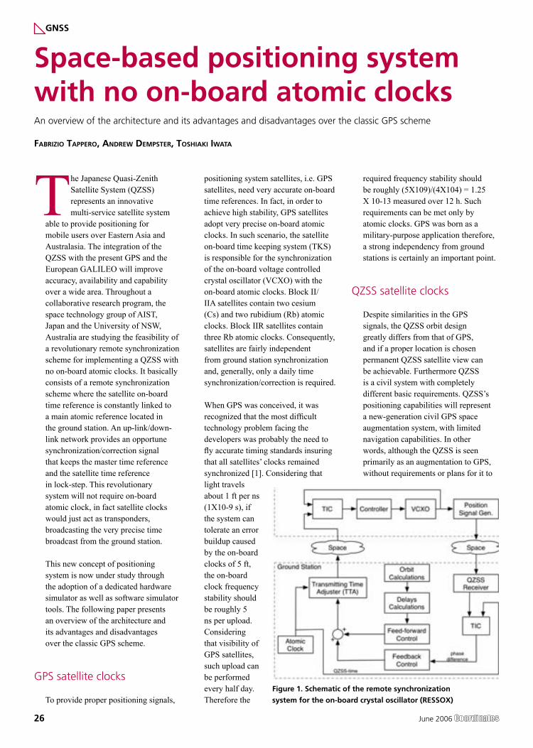
able to provide positioning for mobile users over Eastern Asia and Australasia. The integration of the QZSS with the present GPS and the European GALILEO will improve accuracy, availability and capability over a wide area. Throughout a collaborative research program, the space technology group of AIST, Japan and the University of NSW, Australia are studying the feasibility of a revolutionary remote synchronization scheme for implementing a QZSS with no on-board atomic clocks. It basically consists of a remote synchronization scheme where the satellite on-board time reference is constantly linked to a main atomic reference located in the ground station. An up-link/down-link network provides an opportune synchronization/correction signal that keeps the master time reference and the satellite time reference in lock-step. This revolutionary system will not require on-board atomic clock, in fact satellite clocks would just act as transponders, broadcasting the very precise time broadcast from the ground station.
This new concept of positioning system is now under study through the adoption of a dedicated hardware simulator as well as software simulator tools. The following paper presents an overview of the architecture and its advantages and disadvantages over the classic GPS scheme.
GPS satellite clocks
To provide proper positioning signals,
positioning system satellites, i.e. GPS satellites, need very accurate on-board time references. In fact, in order to achieve high stability, GPS satellites adopt very precise on-board atomic clocks. In such scenario, the satellite on-board time keeping system (TKS) is responsible for the synchronization of the on-board voltage controlled crystal oscillator (VCXO) with the on-board atomic clocks. Block II/IIA satellites contain two cesium (Cs) and two rubidium (Rb) atomic clocks. Block IIR satellites contain three Rb atomic clocks. Consequently, satellites are fairly independent from ground station synchronization and, generally, only a daily time synchronization/correction is required.
When GPS was conceived, it was recognized that the most difficult technology problem facing the developers was probably the need to fly accurate timing standards insuring that all satellites’ clocks remained synchronized [1]. Considering that light travels about 1 ft per ns (1X10⁻⁹ s), if the system can tolerate an error buildup caused by the on-board clocks of 5 ft, the on-board clock frequency stability should be roughly 5 ns per upload. Considering that visibility of GPS satellites, such upload can be performed every half day. Therefore the
required frequency stability should be roughly (5X10⁹)/(4X104) = 1.25 X 10⁻¹³ measured over 12 h. Such requirements can be met only by atomic clocks. GPS was born as a military-purpose application therefore, a strong independency from ground stations is certainly an important point.
QZSS satellite clocks
Despite similarities in the GPS signals, the QZSS orbit design greatly differs from that of GPS, and if a proper location is chosen permanent QZSS satellite view can be achievable. Furthermore QZSS is a civil system with completely different basic requirements. QZSS’s positioning capabilities will represent a new-generation civil GPS space augmentation system, with limited navigation capabilities. In other words, although the QZSS is seen primarily as an augmentation to GPS, without requirements or plans for it to
Space-based positioning system with no on-board atomic clocksAn overview of the architecture and its advantages and disadvantages over the classic GPS scheme
FABRIZIO TAPPERO, ANDREW DEMPSTER, TOSHIAKI IWATA
GNSS
Figure 1. Schematic of the remote synchronization
system for the on-board crystal oscillator (RESSOX)
June 2006 27
work in standalone mode, QZSS can provide limited accuracy positioning on its own. The service also could be augmented with geostationary satellites in Japan’s MTSAT Satellite-based Augmentation System (MSAS) currently under development, which features a geostationary satellite-based design similar to the U.S. Federal Aviation Administration’s Wide Area Augmentation System (WAAS). Details of the QZSS orbit design and signal structure can be found in [2].
According to its original plan, QZSS satellites will be carrying two types of space-born atomic clocks; a hydrogen maser and a rubidium atomic clock. The positioning signal will be generated accordingly to these two clocks and an architecture similar to the GPS TKS will be employed.
QZSS will be also provided with a Two Way Satellite Time a Frequency Transfer, TWSTFT, scheme that will be employed to gain some fundamental knowledge of satellite atomic standard behavior in space and for other research purposes. Among them there is the R&D of a revolutionary time synchronization system that aims to study the feasibility of a no on-board atomic clock GNSS.
No on-board atomic clock GNSS
With a research program started in the 2003, the Space Technology Group in the National Institute of Advanced Industrial Science and Technology (AIST) of Tsukuba, Japan has been studying the feasibility of a novel time synchronization system for QZSS. The novelty of this research is based on the QZSS orbit design and on its high satellite visibility. Such a peculiar feature makes possible to reconsider the classic TKS structure as a remote TKS where the main time reference (atomic clock) is located on the ground in the control station and a correction/synchronization infrastructure keeps the on-board time reference continuously synchronized. Seen in this way the novel TKS for QZSS is indeed a remote
synchronization system (RSS) for the QZSS on board time reference. The feasibility of a synchronization method where one clock is in the ground and the other is flying in space is certainly a non trivial task. [3][4][5][6] are some of the numerous articles that report results of the undergoing research of the QZSS-RSS novel concept.
Feasibility of QZSS-RSS
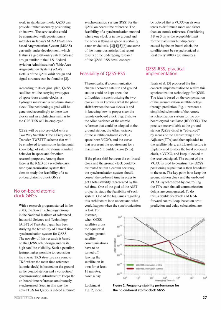
Theoretically, if a communication channel between satellite and ground station could be kept open, the difficulties in synchronizing the two clocks lies in knowing what the phase shift between the two clocks is and in knowing how to proper steer the remote on-board clock. Fig. 2 shows the Allan variance of the atomic reference that could be adopted at the ground station, the Allan variance of the satellite on-board clock, a space-born VCXO, and the curve that represent the requirement for a maximum 5 ft buildup error (5 ns).
If the phase shift between the on-board clock and the ground clock could be estimated within a certain accuracy, the synchronization system should correct the on-board time in order to get a total stability represented by the red time. One of the goal of the AIST project is study the feasibility of such system. One of the big issues regarding this architecture is to understand what could happen when the synchronization is lost. For instance, when QZSS satellites cross the equatorial region, ground-satellite communications have to be turned off, leaving the satellite on its own for at least 11 minutes, twice a day.
Looking at Fig. 2, it can
be noticed that a VCXO on its own tends to drift much more and faster than an atomic reference. Considering 5 ft or 5 ns as the acceptable limit for the maximum buildup error caused by the on-board clock, the satellite must be resynchronized at least every 2000 s (33 minutes).
QZSS-RSS, practical implementation
Iwata et al. [3] proposed the first concrete implementation to realize this synchronization technology for QZSS. The idea is based on the compensation of the ground station satellite delays through prediction. Fig. 1 presents a simplified schematic of the remote synchronization system for the on-board crystal oscillator (RESSOX). The precise time available at the ground station (QZSS-time) is “advanced” by means of the Transmitting Time Adjuster (TTA) and then uploaded to the satellite. Here, a PLL architecture is implemented to steer the local on-board clock, a VCXO, and keep it locked to the received signal. The output of the VCXO is used to construct the QZSS positioning signal that is then broadcast to the user. The key point is to keep the ground station clock and the on-board VCXO synchronized by controlling the TTA such that all communication delays are compensated. To do this, a double feedback and feed-forward control loop, based on orbit prediction and delay calculation, are
Figure 2. Frequency stability performance for
the no on-board atomic clock GNSS
28 June 2006
used. A detailed description of this method can be found in [3] [5].
AIST and the University of NSW are now investigating the feasibility of a second method, a method based on the TWSTFT scheme, available for QZSS. This new control method is characterized by its great simplicity and it is designed specifically for the QZSS. It does not require any on-board atomic clock and, unlike RESSOX does not require any satellite position prediction nor any delay calculation. Its architecture resembles the structure of the TKS for the classic GPS where, instead, the control voltage that drives the VCXO is processed remotely, in the ground station. Hence it has been named Remote Time Keeping System, RTKS. In [4] the TWTT method and its implementations in the QZSS are described.
Phase shift measurement
As mentioned early, the real-time or quasi real-time determination of the phase shift between the ground station clock and the on-board clock, is a fundamental requirement for the realization of QZSS-RSS. Presently two strategies are under study. The architecture proposed in [3], being totally based on satellite position prediction and delay estimation, relies on the ability of predicting what the phase shift is. The implementation of an additional feedback that make the whole system more robust in now under study. Synchronization accuracy of the order of 4 ns are achievable for this scheme.
The second architecture, recently proposed in [4] takes advantage of the TWSTFT scheme. Now under test on board the ETS-VIII and, in the future, available for QZSS, the TWSTFT method is expected to offer accuracy of the nanosecond order at all times.
VCXO control Algorithm
One of the key points for the realization of RSS for RESSOX is the implementation of a controller for the on-board VCXO that can combine the
good short-term stability of the VCXO with the good long-term stability of the ground station atomic standard. When the synchronization information is upload-able, such controller should be able to keep the VCXO looked to the ground station clock within acceptable limits. In [6] the authors report a successful implementation of such controller where the Allan variance of the controlled VCXO is largely below the 5 ns requirements.
Conclusions
With the opportune shrewdness, the basic idea that lies behind the QZSS-RSS could theoretically be applied to other GNSSs. The two proposed methods, [3] [4], are practical implementations of this remote synchronization concept specifically made for QZSS. Both schemes could theoretically be applicable to a world-wide GNSS, i.e. GPS or GALILEO. For such systems, all time view is not applicable and more ground stations would be necessary to guarantee the necessary synchronization update. Beside being a very interesting research topic, the idea of a GNSS with no on-board atomic clocks would offer several advantages in term of satellite cost, life expectancy and satellite power consumption. This concept could be advantageously applicable to Low Earth Orbit, LEO, positioning systems, [7], where satellite weight is clearly a critical issue.
References
[1] Bradford, W., Parkinson, J.J., Spilker, Jr.: Global Positioning System: Theory and Applications Volume I, AIAA, (1996).
[2] Petrovski IG et al. QZSS - Japan’s New Integrated Communication and Positioning Service for Mobile Users, 2006, GPS World, vol. 14, n.6, pp 24-29.
[3] Iwata, T. et al. Remote Synchronization System for On-Board Crystal Oscillator of
Quasi-Zenith Satellite System, International Symposium on GPS/GNSS, 2003, pp. 375-380.
[4] Tappero et al. Remote Control System for the Quasi-Zenith Satellite Crystal Oscillator Based On the Two-Way Time Transfer Method . IGNSS Symposium 2006. 17, 21 July 2006. Holiday Inn Surfers Paradise, Australia.
[5] Tappero et al. Hardware Experimental Setup for the Remote Synchronization System of Onboard Crystal Oscillator. 48th Space Sciences and Technology Conference, Fukui, Japan, 4-6 Nov. 2004.
[6] Tappero et al. Control Algorithm of the Hardware Simulator For a Remote Synchronization System for the Japanese Quasi-Zenith Satellite System. ION NTM 2005 Conference, January 24-26, 2005, in San Diego.
[7] Regional positioning system using low earth orbit constellations, Der-Ming Ma. Acta Astronautica. 2006, vol. 58, pp 387-394.
Fabrizio Tappero School of Surveying & Spatial Information Systems, The University of New
South Wales, Sydney, Australia [email protected]
Andrew Dempster, Director of Research, School of Surveying & Spatial Information Systems, The University
of New South Wales, Sydney, Australia [email protected]
Toshiaki Iwata National Institute of Advanced Industrial Science and Technology (AIST) Tsukuba,Japan
June 2006 29
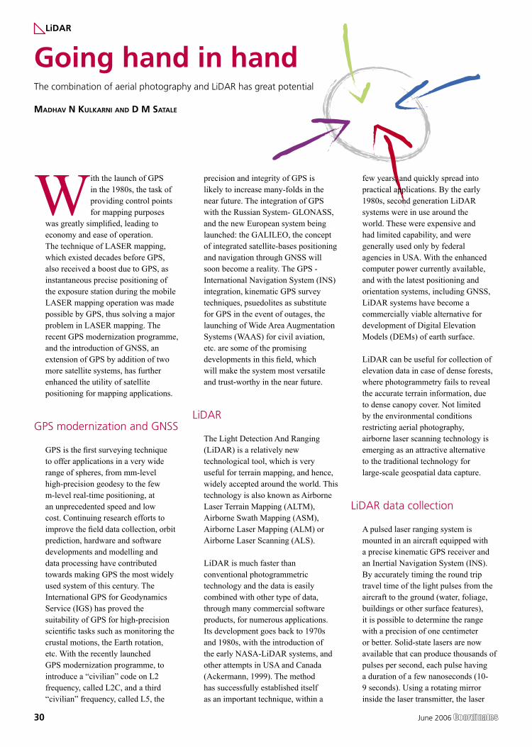
30 June 2006
With the launch of GPS in the 1980s, the task of providing control points for mapping purposes
was greatly simplified, leading to economy and ease of operation. The technique of LASER mapping, which existed decades before GPS, also received a boost due to GPS, as instantaneous precise positioning of the exposure station during the mobile LASER mapping operation was made possible by GPS, thus solving a major problem in LASER mapping. The recent GPS modernization programme, and the introduction of GNSS, an extension of GPS by addition of two more satellite systems, has further enhanced the utility of satellite positioning for mapping applications.
GPS modernization and GNSS
GPS is the first surveying technique to offer applications in a very wide range of spheres, from mm-level high-precision geodesy to the few m-level real-time positioning, at an unprecedented speed and low cost. Continuing research efforts to improve the field data collection, orbit prediction, hardware and software developments and modelling and data processing have contributed towards making GPS the most widely used system of this century. The International GPS for Geodynamics Service (IGS) has proved the suitability of GPS for high-precision scientific tasks such as monitoring the crustal motions, the Earth rotation, etc. With the recently launched GPS modernization programme, to introduce a “civilian” code on L2 frequency, called L2C, and a third “civilian” frequency, called L5, the
precision and integrity of GPS is likely to increase many-folds in the near future. The integration of GPS with the Russian System- GLONASS, and the new European system being launched: the GALILEO, the concept of integrated satellite-bases positioning and navigation through GNSS will soon become a reality. The GPS - International Navigation System (INS) integration, kinematic GPS survey techniques, psuedolites as substitute for GPS in the event of outages, the launching of Wide Area Augmentation Systems (WAAS) for civil aviation, etc. are some of the promising developments in this field, which will make the system most versatile and trust-worthy in the near future.
LiDAR
The Light Detection And Ranging (LiDAR) is a relatively new technological tool, which is very useful for terrain mapping, and hence, widely accepted around the world. This technology is also known as Airborne Laser Terrain Mapping (ALTM), Airborne Swath Mapping (ASM), Airborne Laser Mapping (ALM) or Airborne Laser Scanning (ALS).
LiDAR is much faster than conventional photogrammetric technology and the data is easily combined with other type of data, through many commercial software products, for numerous applications. Its development goes back to 1970s and 1980s, with the introduction of the early NASA-LiDAR systems, and other attempts in USA and Canada (Ackermann, 1999). The method has successfully established itself as an important technique, within a
few years, and quickly spread into practical applications. By the early 1980s, second generation LiDAR systems were in use around the world. These were expensive and had limited capability, and were generally used only by federal agencies in USA. With the enhanced computer power currently available, and with the latest positioning and orientation systems, including GNSS, LiDAR systems have become a commercially viable alternative for development of Digital Elevation Models (DEMs) of earth surface.
LiDAR can be useful for collection of elevation data in case of dense forests, where photogrammetry fails to reveal the accurate terrain information, due to dense canopy cover. Not limited by the environmental conditions restricting aerial photography, airborne laser scanning technology is emerging as an attractive alternative to the traditional technology for large-scale geospatial data capture.
LiDAR data collection
A pulsed laser ranging system is mounted in an aircraft equipped with a precise kinematic GPS receiver and an Inertial Navigation System (INS). By accurately timing the round trip travel time of the light pulses from the aircraft to the ground (water, foliage, buildings or other surface features), it is possible to determine the range with a precision of one centimeter or better. Solid-state lasers are now available that can produce thousands of pulses per second, each pulse having a duration of a few nanoseconds (10-9 seconds). Using a rotating mirror inside the laser transmitter, the laser
Going hand in handThe combination of aerial photography and LiDAR has great potential
MADHAV N KULKARNI AND D M SATALE
LiDAR
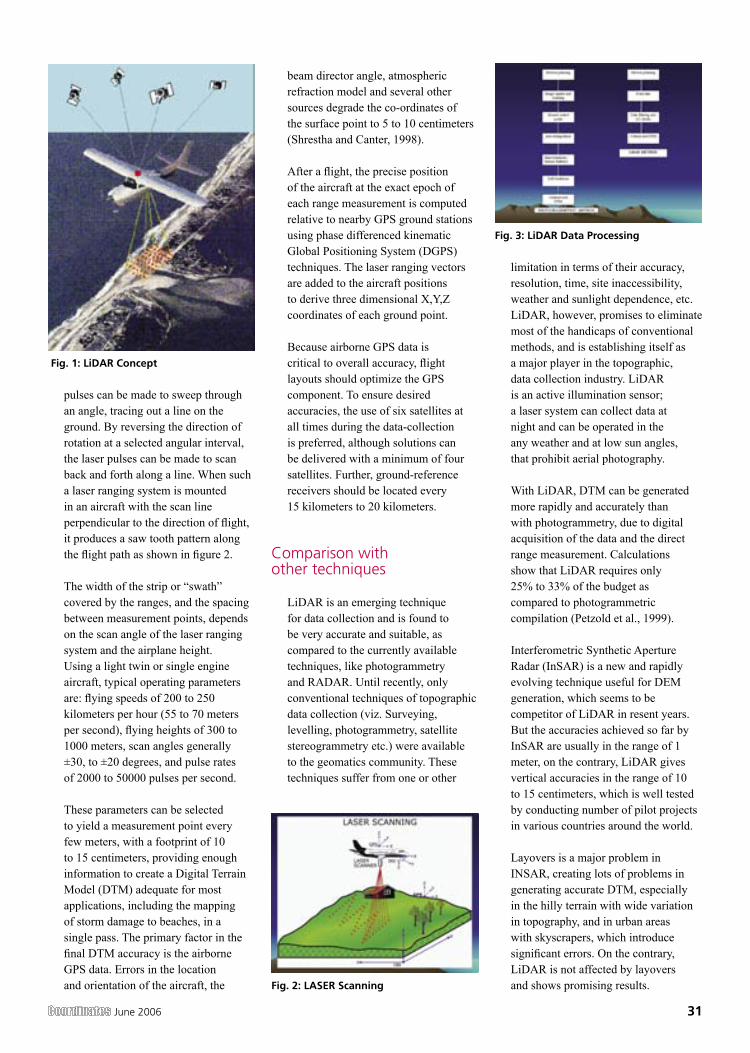
June 2006 31
pulses can be made to sweep through an angle, tracing out a line on the ground. By reversing the direction of rotation at a selected angular interval, the laser pulses can be made to scan back and forth along a line. When such a laser ranging system is mounted in an aircraft with the scan line perpendicular to the direction of flight, it produces a saw tooth pattern along the flight path as shown in figure 2.
The width of the strip or “swath” covered by the ranges, and the spacing between measurement points, depends on the scan angle of the laser ranging system and the airplane height. Using a light twin or single engine aircraft, typical operating parameters are: flying speeds of 200 to 250 kilometers per hour (55 to 70 meters per second), flying heights of 300 to 1000 meters, scan angles generally ±30, to ±20 degrees, and pulse rates of 2000 to 50000 pulses per second.
These parameters can be selected to yield a measurement point every few meters, with a footprint of 10 to 15 centimeters, providing enough information to create a Digital Terrain Model (DTM) adequate for most applications, including the mapping of storm damage to beaches, in a single pass. The primary factor in the final DTM accuracy is the airborne GPS data. Errors in the location and orientation of the aircraft, the
beam director angle, atmospheric refraction model and several other sources degrade the co-ordinates of the surface point to 5 to 10 centimeters (Shrestha and Canter, 1998).
After a flight, the precise position of the aircraft at the exact epoch of each range measurement is computed relative to nearby GPS ground stations using phase differenced kinematic Global Positioning System (DGPS) techniques. The laser ranging vectors are added to the aircraft positions to derive three dimensional X,Y,Z coordinates of each ground point.
Because airborne GPS data is critical to overall accuracy, flight layouts should optimize the GPS component. To ensure desired accuracies, the use of six satellites at all times during the data-collection is preferred, although solutions can be delivered with a minimum of four satellites. Further, ground-reference receivers should be located every 15 kilometers to 20 kilometers.
Comparison with other techniques
LiDAR is an emerging technique for data collection and is found to be very accurate and suitable, as compared to the currently available techniques, like photogrammetry and RADAR. Until recently, only conventional techniques of topographic data collection (viz. Surveying, levelling, photogrammetry, satellite stereogrammetry etc.) were available to the geomatics community. These techniques suffer from one or other
limitation in terms of their accuracy, resolution, time, site inaccessibility, weather and sunlight dependence, etc. LiDAR, however, promises to eliminate most of the handicaps of conventional methods, and is establishing itself as a major player in the topographic, data collection industry. LiDAR is an active illumination sensor; a laser system can collect data at night and can be operated in the any weather and at low sun angles, that prohibit aerial photography.
With LiDAR, DTM can be generated more rapidly and accurately than with photogrammetry, due to digital acquisition of the data and the direct range measurement. Calculations show that LiDAR requires only 25% to 33% of the budget as compared to photogrammetric compilation (Petzold et al., 1999).
Interferometric Synthetic Aperture Radar (InSAR) is a new and rapidly evolving technique useful for DEM generation, which seems to be competitor of LiDAR in resent years. But the accuracies achieved so far by InSAR are usually in the range of 1 meter, on the contrary, LiDAR gives vertical accuracies in the range of 10 to 15 centimeters, which is well tested by conducting number of pilot projects in various countries around the world.
Layovers is a major problem in INSAR, creating lots of problems in generating accurate DTM, especially in the hilly terrain with wide variation in topography, and in urban areas with skyscrapers, which introduce significant errors. On the contrary, LiDAR is not affected by layovers and shows promising results.
Fig. 1: LiDAR Concept
Fig. 2: LASER Scanning
Fig. 3: LiDAR Data Processing
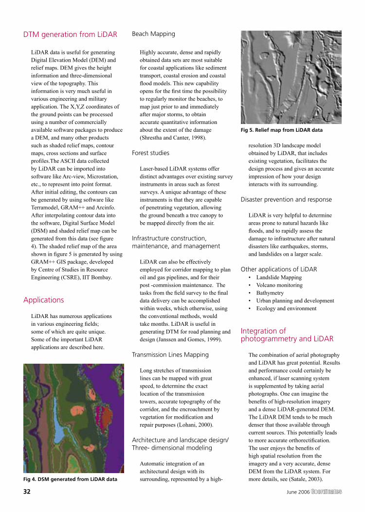
32 June 2006
DTM generation from LiDAR
LiDAR data is useful for generating Digital Elevation Model (DEM) and relief maps. DEM gives the height information and three-dimensional view of the topography. This information is very much useful in various engineering and military application. The X,Y,Z coordinates of the ground points can be processed using a number of commercially available software packages to produce a DEM, and many other products such as shaded relief maps, contour maps, cross sections and surface profiles.The ASCII data collected by LiDAR can be imported into software like Arc-view, Microstation, etc., to represent into point format. After initial editing, the contours can be generated by using software like Terramodel, GRAM++ and Arcinfo. After interpolating contour data into the software, Digital Surface Model (DSM) and shaded relief map can be generated from this data (see figure 4). The shaded relief map of the area shown in figure 5 is generated by using GRAM++ GIS package, developed by Centre of Studies in Resource Engineering (CSRE), IIT Bombay.
Applications
LiDAR has numerous applications in various engineering fields; some of which are quite unique. Some of the important LiDAR applications are described here.
Beach Mapping
Highly accurate, dense and rapidly obtained data sets are most suitable for coastal applications like sediment transport, coastal erosion and coastal flood models. This new capability opens for the first time the possibility to regularly monitor the beaches, to map just prior to and immediately after major storms, to obtain accurate quantitative information about the extent of the damage (Shrestha and Canter, 1998).
Forest studies
Laser-based LiDAR systems offer distinct advantages over existing survey instruments in areas such as forest surveys. A unique advantage of these instruments is that they are capable of penetrating vegetation, allowing the ground beneath a tree canopy to be mapped directly from the air.
Infrastructure construction, maintenance, and management
LiDAR can also be effectively employed for corridor mapping to plan oil and gas pipelines, and for their post -commission maintenance. The tasks from the field survey to the final data delivery can be accomplished within weeks, which otherwise, using the conventional methods, would take months. LiDAR is useful in generating DTM for road planning and design (Janssen and Gomes, 1999).
Transmission Lines Mapping
Long stretches of transmission lines can be mapped with great speed, to determine the exact location of the transmission towers, accurate topography of the corridor, and the encroachment by vegetation for modification and repair purposes (Lohani, 2000).
Architecture and landscape design/ Three- dimensional modeling
Automatic integration of an architectural design with its surrounding, represented by a high-
resolution 3D landscape model obtained by LiDAR, that includes existing vegetation, facilitates the design process and gives an accurate impression of how your design interacts with its surrounding.
Disaster prevention and response
LiDAR is very helpful to determine areas prone to natural hazards like floods, and to rapidly assess the damage to infrastructure after natural disasters like earthquakes, storms, and landslides on a larger scale.
Other applications of LiDAR • Landslide Mapping• Volcano monitoring• Bathymetry• Urban planning and development• Ecology and environment
Integration of photogrammetry and LiDAR
The combination of aerial photography and LiDAR has great potential. Results and performance could certainly be enhanced, if laser scanning system is supplemented by taking aerial photographs. One can imagine the benefits of high-resolution imagery and a dense LiDAR-generated DEM. The LiDAR DEM tends to be much denser that those available through current sources. This potentially leads to more accurate orthorectification. The user enjoys the benefits of high spatial resolution from the imagery and a very accurate, dense DEM from the LiDAR system. For more details, see (Satale, 2003). Fig 4. DSM generated from LiDAR data
Fig 5. Relief map from LiDAR data
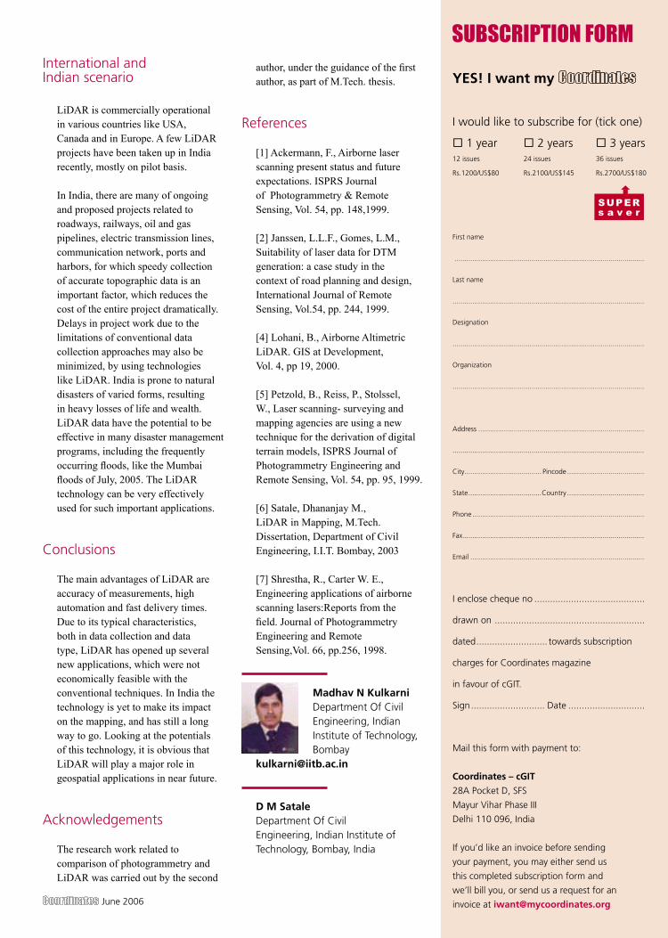
June 2006 33
YES! I want my
I would like to subscribe for (tick one)
1 year 2 years 3 years12 issues 24 issues 36 issues
Rs.1200/US$80 Rs.2100/US$145 Rs.2700/US$180
First name
................................................................................................
Last name
.................................................................................................
Designation
.................................................................................................
Organization
.................................................................................................
Address ....................................................................................
.................................................................................................
City ....................................... Pincode .......................................
State .....................................Country .......................................
Phone .......................................................................................
Fax ............................................................................................
Email ........................................................................................
I enclose cheque no ..........................................
drawn on .........................................................
dated ........................... towards subscription
charges for Coordinates magazine
in favour of cGIT.
Sign ............................ Date .............................
Mail this form with payment to:
Coordinates – cGIT
28A Pocket D, SFS
Mayur Vihar Phase III
Delhi 110 096, India
If you’d like an invoice before sending
your payment, you may either send us
this completed subscription form and
we’ll bill you, or send us a request for an
invoice at [email protected]
International and Indian scenario
LiDAR is commercially operational in various countries like USA, Canada and in Europe. A few LiDAR projects have been taken up in India recently, mostly on pilot basis.
In India, there are many of ongoing and proposed projects related to roadways, railways, oil and gas pipelines, electric transmission lines, communication network, ports and harbors, for which speedy collection of accurate topographic data is an important factor, which reduces the cost of the entire project dramatically. Delays in project work due to the limitations of conventional data collection approaches may also be minimized, by using technologies like LiDAR. India is prone to natural disasters of varied forms, resulting in heavy losses of life and wealth. LiDAR data have the potential to be effective in many disaster management programs, including the frequently occurring floods, like the Mumbai floods of July, 2005. The LiDAR technology can be very effectively used for such important applications.
Conclusions
The main advantages of LiDAR are accuracy of measurements, high automation and fast delivery times. Due to its typical characteristics, both in data collection and data type, LiDAR has opened up several new applications, which were not economically feasible with the conventional techniques. In India the technology is yet to make its impact on the mapping, and has still a long way to go. Looking at the potentials of this technology, it is obvious that LiDAR will play a major role in geospatial applications in near future.
Acknowledgements
The research work related to comparison of photogrammetry and LiDAR was carried out by the second
author, under the guidance of the first author, as part of M.Tech. thesis.
References
[1] Ackermann, F., Airborne laser scanning present status and future expectations. ISPRS Journal of Photogrammetry & Remote Sensing, Vol. 54, pp. 148,1999.
[2] Janssen, L.L.F., Gomes, L.M., Suitability of laser data for DTM generation: a case study in the context of road planning and design, International Journal of Remote Sensing, Vol.54, pp. 244, 1999.
[4] Lohani, B., Airborne Altimetric LiDAR. GIS at Development, Vol. 4, pp 19, 2000.
[5] Petzold, B., Reiss, P., Stolssel, W., Laser scanning- surveying and mapping agencies are using a new technique for the derivation of digital terrain models, ISPRS Journal of Photogrammetry Engineering and Remote Sensing, Vol. 54, pp. 95, 1999.
[6] Satale, Dhananjay M., LiDAR in Mapping, M.Tech. Dissertation, Department of Civil Engineering, I.I.T. Bombay, 2003
[7] Shrestha, R., Carter W. E., Engineering applications of airborne scanning lasers:Reports from the field. Journal of Photogrammetry Engineering and Remote Sensing,Vol. 66, pp.256, 1998.
Madhav N Kulkarni Department Of Civil Engineering, Indian Institute of Technology, Bombay
D M Satale Department Of Civil Engineering, Indian Institute of Technology, Bombay, India
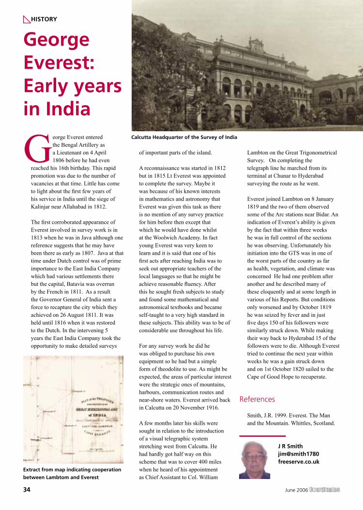
34 June 2006
George Everest entered the Bengal Artillery as a Lieutenant on 4 April 1806 before he had even
reached his 16th birthday. This rapid promotion was due to the number of vacancies at that time. Little has come to light about the first few years of his service in India until the siege of Kalinjar near Allahabad in 1812.
The first corroborated appearance of Everest involved in survey work is in 1813 when he was in Java although one reference suggests that he may have been there as early as 1807. Java at that time under Dutch control was of prime importance to the East India Company which had various settlements there but the capital, Batavia was overrun by the French in 1811. As a result the Governor General of India sent a force to recapture the city which they achieved on 26 August 1811. It was held until 1816 when it was restored to the Dutch. In the intervening 5 years the East India Company took the opportunity to make detailed surveys
of important parts of the island.
A reconnaissance was started in 1812 but in 1815 Lt Everest was appointed to complete the survey. Maybe it was because of his known interests in mathematics and astronomy that Everest was given this task as there is no mention of any survey practice for him before then except that which he would have done whilst at the Woolwich Academy. In fact young Everest was very keen to learn and it is said that one of his first acts after reaching India was to seek out appropriate teachers of the local languages so that he might be achieve reasonable fluency. After this he sought fresh subjects to study and found some mathematical and astronomical textbooks and became self-taught to a very high standard in these subjects. This ability was to be of considerable use throughout his life.
For any survey work he did he was obliged to purchase his own equipment so he had but a simple form of theodolite to use. As might be expected, the areas of particular interest were the strategic ones of mountains, harbours, communication routes and near-shore waters. Everest arrived back in Calcutta on 20 November 1916.
A few months later his skills were sought in relation to the introduction of a visual telegraphic system stretching west from Calcutta. He had hardly got half way on this scheme that was to cover 400 miles when he heard of his appointment as Chief Assistant to Col. William
Lambton on the Great Trigonometrical Survey. On completing the telegraph line he marched from its terminal at Chunar to Hyderabad surveying the route as he went.
Everest joined Lambton on 8 January 1819 and the two of them observed some of the Arc stations near Bidar. An indication of Everest’s ability is given by the fact that within three weeks he was in full control of the sections he was observing. Unfortunately his initiation into the GTS was in one of the worst parts of the country as far as health, vegetation, and climate was concerned He had one problem after another and he described many of these eloquently and at some length in various of his Reports. But conditions only worsened and by October 1819 he was seized by fever and in just five days 150 of his followers were similarly struck down. While making their way back to Hyderabad 15 of the followers were to die. Although Everest tried to continue the next year within weeks he was a gain struck down and on 1st October 1820 sailed to the Cape of Good Hope to recuperate.
References
Smith, J.R. 1999. Everest. The Man and the Mountain. Whittles, Scotland.
George Everest: Early years in India
J R Smith jim@smith1780 freeserve.co.uk
HISTORY
Calcutta Headquarter of the Survey of India
Extract from map indicating cooperation
between Lambtom and Everest

June 2006 35
36 June 2006
In India, the “extra” digits in telephone numbers have been added a number of times e.g., the digits for Delhi have changed from 5 to
8 in the past five decades. However, with the addition of extra digit of “2” (or “3” or “5”) in the phone numbers of the cities around the countries in December 2002, the total number has reached to “10”, i.e., “2, 3, or 4” digits of city codes plus “8, 7, or 6” digits of phone numbers. In one colony of Delhi, since December 2002, the phone numbers have changed from 2527-1234 to 3097-1234 and then to 3297-1234, i.e., three times in three years.
Forthcoming future
In a few countries in Western Europe, 9-digit phone numbers have already started popping out. In case of India with one billion plus population and booming popularity of mobile phones, addition of an “extra” digit in phone numbers is a distinct possibility. Furthermore, India might need a new series of “village” codes, as phones would become popular with villagers.
Opportunity waiting
The “10-digit” phone numbers now provide an opportunity that India’s phone numbering system can be redesigned into a new format of “3” digit area codes, as a replacement of present city codes, plus the “7” digit phone numbers to replace the variable digits. This will also eliminate the need for adding of extra digits into phone numbers in the future.
Future adding of phones
As the new phone numbers grow in any state, city, or “area”, a new “3” digit
area code can be added with a set of 10 million “7” digit phone numbers.
Easy updating
First Step -
The present practice of dialing 10-digits for mobile phones or city codes and phone numbers for Delhi and its neighboring cities should be extended to all “other” areas and phones. Thus, this would require that the “city” codes are to be included in all phone calls for all over India.
Second Step -
Once the 10-digit dialing (Step 1) becomes an All India feature, then the “city code plus phone number” is to be reformatted to “area code plus phone number” as per the scheme detailed below.
Suggested “Reformatted” scheme
The complete reformatted numbering scheme will evolve as under:
Area Codes:
b. Adding New Numbers in the Future:
As the need to add new numbers arises in the future, a NEW
area code can be added: 114-nnn-mmmm; 115-nnn-mmmm;
so on for Delhi. 223-nnn-mmmm; 224-nnn-mmmm; 226-nnn-mmmm; so on for Mumbai.
This system will have provision
for addition of 10 million numbers under any one new area code. It will not “overflow” in the next 50 years or so.
Caution: The addition of numbers
for ALL new phones, due to (1) introduction of a new phone company or type and (2) new phone line, must be an integral part of the unified national numbering scheme.
Calling within and between area codes -
a) Within the same area code - No need to dial the preceding “0”. b) Toll calling between any
two area codes - A caller will be required to dial “0”
before dialing the “10” digit number (3-digit area code + 7-digit phone number) of the “OTHER” area. ALL calls with preceding “0” will be subjected to TOLL charges.
c) Free calling between two “neighboring” area codes
In cases like NOIDA and Delhi, where the calls are considered local with no charges, callers will not need to add a “0”. If a “0” is added (when caller may not be certain whether the call is local), the computer will IGNORE the zero.
NOTE: This procedure will standardize the toll-free
calling between neighboring area codes.
Cell phone numbering Once the new scheme is accepted,
India’s phone coordinatesEasy 2-Steps to a “Smooth and Convenient” Future!
MUNEENDRA KUMAR, PHD, [email protected]
PERSPECTIVE
June 2006 37
it will also be the right timing to regulate the growth in mobile phone numbers in a “designed” area code type format.
a) Grouping in area codes States (in varying numbers) could
be grouped into “area” code format for future expansion. The present “open” numbers starting with “98” should be regulated immediately.
b Future extensions As an example, Delhi area codes
can be as 971, 961, 951, and so on. Once the series starting with “9” overflows, a new series could be designed with “8”.
c) Toll calls To start a “toll” call, e.g., between
two area codes of mobile phones, caller will be using “0”.
Special area codesa) Toll free Area codes like “600, 700,
and 800” should be reserved to start with. Also, area codes like 666, 777, 888 can also be reserved for future expansion.
Toll free calls to these numbers should not be allowed from
outside the country to any caller.b) Toll Code(s) To start, code 900 can be designated
where the caller pays to obtain a special service or information from a commercial firm or agency.
In all such a case, the commercial firm or agency must advertise and/or inform the caller right at the start of the call about the charge(s) per minute to protect the users of malpractice.
c) Government codes Central Government – 100 State Governments - 101,
102, 103, and so on.d) Tourism codes Codes “555” and “999” could
be reserved for tourism.
Special numberinga) Emergency from Anywhere - “911” (w/o Area Code) Medical Hflp (Local) - “811” Traffic Help (Local) - “711” Police (Local) - “611”b) Phone Enquiry (Local) - “511” c) Alphabet s - “2
for a, b, c”, “3 for c, d, e”, “4 for f, g, h”, “5 for I, j, k”, “6 for m,
n, o”, “7 for p, q, r, s”, “8 for t, u, v”, and “9 for w, x, y, z”.
ExamplesEmergency - 911(From Anywhere)Holiday Inn in -222-HOLIDAYMumbaiMarriott in Delhi - 112 MARRIOTT (Last digit is ignored) Air India in -112-AIR- INDIA Delhi (Last digit is ignored)Central Health 100-4-HEALTHMinistryState Tourism 101-TOURISM Office Phone Enquiry - 112-511in Delhi (From other area codes)
Summary
A unified and integrated national telephone numbering scheme will ensure in easy 2-steps “Good Phone Coordinates” for a smooth and convenient future!
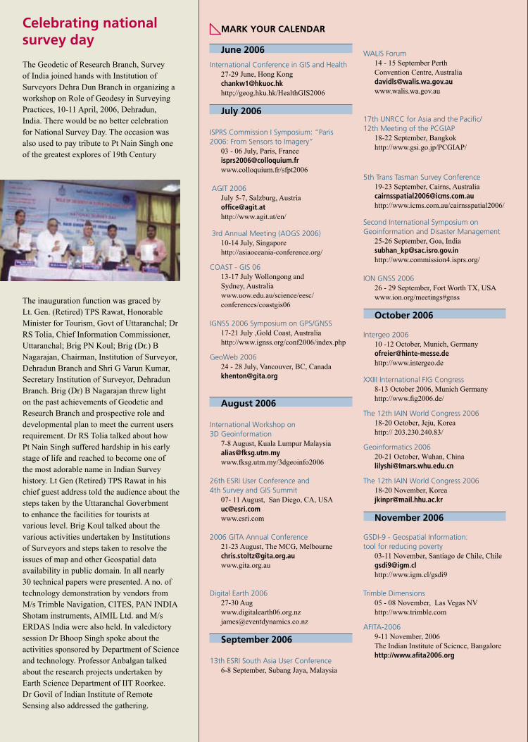
38 June 2006
The Geodetic of Research Branch, Survey of India joined hands with Institution of Surveyors Dehra Dun Branch in organizing a workshop on Role of Geodesy in Surveying Practices, 10-11 April, 2006, Dehradun, India. There would be no better celebration for National Survey Day. The occasion was also used to pay tribute to Pt Nain Singh one of the greatest explores of 19th Century
The inauguration function was graced by Lt. Gen. (Retired) TPS Rawat, Honorable Minister for Tourism, Govt of Uttaranchal; Dr RS Tolia, Chief Information Commissioner, Uttaranchal; Brig PN Koul; Brig (Dr.) B Nagarajan, Chairman, Institution of Surveyor, Dehradun Branch and Shri G Varun Kumar, Secretary Institution of Surveyor, Dehradun Branch. Brig (Dr) B Nagarajan threw light on the past achievements of Geodetic and Research Branch and prospective role and developmental plan to meet the current users requirement. Dr RS Tolia talked about how Pt Nain Singh suffered hardship in his early stage of life and reached to become one of the most adorable name in Indian Survey history. Lt Gen (Retired) TPS Rawat in his chief guest address told the audience about the steps taken by the Uttaranchal Goverbment to enhance the facilities for tourists at various level. Brig Koul talked about the various activities undertaken by Institutions of Surveyors and steps taken to resolve the issues of map and other Geospatial data availability in public domain. In all nearly 30 technical papers were presented. A no. of technology demonstration by vendors from M/s Trimble Navigation, CITES, PAN INDIA Shotam instruments, AIMIL Ltd. and M/s ERDAS India were also held. In valedictory session Dr Bhoop Singh spoke about the activities sponsored by Department of Science and technology. Professor Anbalgan talked about the research projects undertaken by Earth Science Department of IIT Roorkee. Dr Govil of Indian Institute of Remote Sensing also addressed the gathering.
Celebrating national survey day
MARK YOUR CALENDAR
June 2006
International Conference in GIS and Health 27-29 June, Hong [email protected];//geog.hku.hk/HealthGIS2006
July 2006
ISPRS Commission I Symposium: “Paris 2006: From Sensors to Imagery”
03 - 06 July, Paris, [email protected] www.colloquium.fr/sfpt2006
AGIT 2006July 5-7, Salzburg, [email protected]://www.agit.at/en/
3rd Annual Meeting (AOGS 2006) 10-14 July, Singapore http://asiaoceania-conference.org/
COAST - GIS 0613-17 July Wollongong and Sydney, Australiawww.uow.edu.au/science/eesc/conferences/coastgis06
IGNSS 2006 Symposium on GPS/GNSS 17-21 July ,Gold Coast, Australia http://www.ignss.org/conf2006/index.php
GeoWeb 200624 - 28 July, Vancouver, BC, [email protected]
August 2006
International Workshop on 3D Geoinformation
7-8 August, Kuala Lumpur Malaysia [email protected] www.fksg.utm.my/3dgeoinfo2006
26th ESRI User Conference and 4th Survey and GIS Summit
07- 11 August, San Diego, CA, USA [email protected] www.esri.com
2006 GITA Annual Conference21-23 August, The MCG, [email protected]
Digital Earth 2006 27-30 Aug www.digitalearth06.org.nz [email protected]
September 2006
13th ESRI South Asia User Conference6-8 September, Subang Jaya, Malaysia
WALIS Forum14 - 15 September Perth Convention Centre, Australia [email protected]
17th UNRCC for Asia and the Pacific/12th Meeting of the PCGIAP
18-22 September, Bangkokhttp://www.gsi.go.jp/PCGIAP/
5th Trans Tasman Survey Conference19-23 September, Cairns, [email protected]://www.icms.com.au/cairnsspatial2006/
Second International Symposium on Geoinformation and Disaster Management
25-26 September, Goa, [email protected]://www.commission4.isprs.org/
ION GNSS 200626 - 29 September, Fort Worth TX, USAwww.ion.org/meetings#gnss
October 2006
Intergeo 2006 10 -12 October, Munich, Germany [email protected] http://www.intergeo.de
XXIII International FIG Congress8-13 October 2006, Munich Germanyhttp://www.fig2006.de/
The 12th IAIN World Congress 2006 18-20 October, Jeju, Koreahttp:// 203.230.240.83/
Geoinformatics 200620-21 October, Wuhan, [email protected]
The 12th IAIN World Congress 200618-20 November, [email protected]
November 2006
GSDI-9 - Geospatial Information: tool for reducing poverty
03-11 November, Santiago de Chile, Chile [email protected] http://www.igm.cl/gsdi9
Trimble Dimensions 05 - 08 November, Las Vegas NV http://www.trimble.com
AFITA-20069-11 November, 2006The Indian Institute of Science, Bangalorehttp://www.afita2006.org
ION GNSS 2006September 26–29, 2006���Fort Worth, Texas
�����������
Attend the World’s Largest Technical Meeting and Showcase of GNSS Technology, Products and Services!
��Beat the Stampede, Register Early!
� Exhibit Space Is Still Available
� Early Registration & Advance Hotel Reservation Deadline: Sept. 1
� Multipath� Military Applications� Algorithms for Multi-sensor Fusion� Alternatives and Backups to GNSS� Surveying and Geodesy� Precise Point Positioning� Network-Based RTK� Military Landing Systems� New Product Announcements� Novel Applications� Open Source Software� GNSS Receiver Algorithms� GNSS Meteorology� Atmospheric Effects on GNSS� Software Receivers–GNSS� Software Receivers–Applications� Algorithms and Methods� Timing and Scientific Applications� Indoor Positioning� Land Applications� Marine Applications� Aviation Applications� Galileo System Design� GNSS Space Based Augmentation� Space and Satellite Applications� GNSS Antenna & Radio Technology� Galileo Integrity,
Multi-constellation RAIM� Galileo and GPS/Galileo
Reference and User Receivers� GNSS Ground Based
Augmentation Systems� Galileo Institutional, Standardiza-
tion and Application Development� Galileo Signal Structure,
GPS/Galileo Interoperability� GPS and GLONASS
Modernization, QZSS� Remote Sensing With GPS
and Integrated Sensors� Integrated Navigation Systems Us-
ing GNSS, INS & Auxiliary Sensors� GNSS Civil Interference
and Spectrum Aspects
� MultipathSession Topics
�������������������������������������������������������������������������������������������
��Tutorials: Sept. 25–26
������������������
4 March 2006


![Convergence of Wachspress coordinates: from polygons to ...jiri/papers/14KoBa.pdf · convex polygons are Wachspress coordinates [14], mean value coordinates [4], and harmonic coordinates](https://img.pdfslide.us/doc/110x75/5f6dfe23261f61015179236e/convergence-of-wachspress-coordinates-from-polygons-to-jiripapers-convex.jpg)