Embed Size (px)
Citation preview

图形学可能的新机遇减材制造
报告: 赵海森
导师:陈宝权教授
山东大学 交叉研究中心
2018.06.21
GAMES Webinar 51期
Email: [email protected]: http://www.cs.sdu.edu.cn/irc/~zhaohaisen/


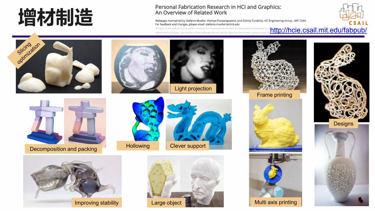
Decomposition and packing
Improving stability Large object
Light projection
Clever support
Designs
Hollowing
Multi axis printing
Frame printing
http://hcie.csail.mit.edu/fabpub/增材制造
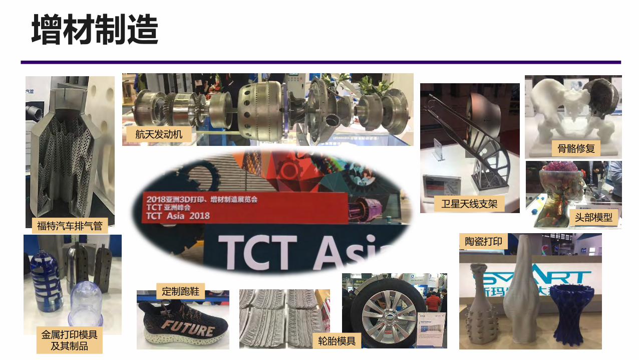
增材制造
航天发动机
福特汽车排气管
骨骼修复
定制跑鞋
陶瓷打印
金属打印模具及其制品 轮胎模具
卫星天线支架
头部模型
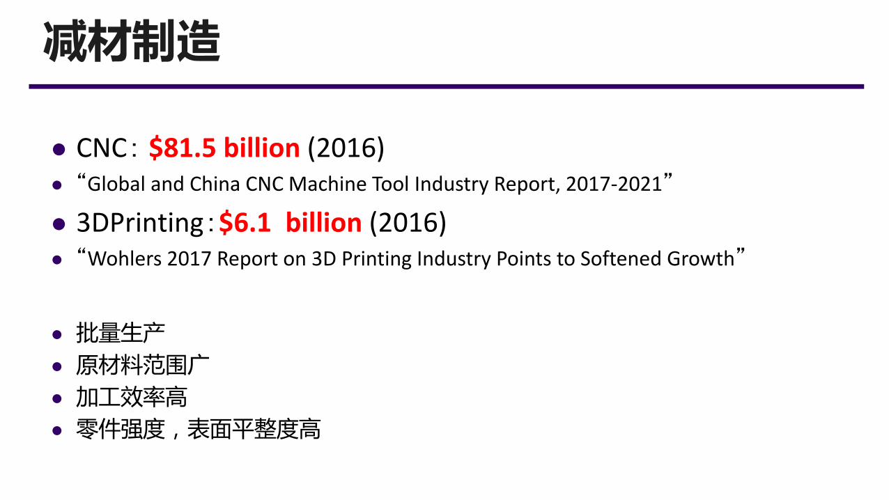
减材制造
⚫ CNC: $81.5 billion (2016)⚫ “Global and China CNC Machine Tool Industry Report, 2017-2021”
⚫ 3DPrinting:$6.1 billion (2016)⚫ “Wohlers 2017 Report on 3D Printing Industry Points to Softened Growth”
⚫ 批量生产
⚫ 原材料范围广
⚫ 加工效率高
⚫ 零件强度,表面平整度高
7
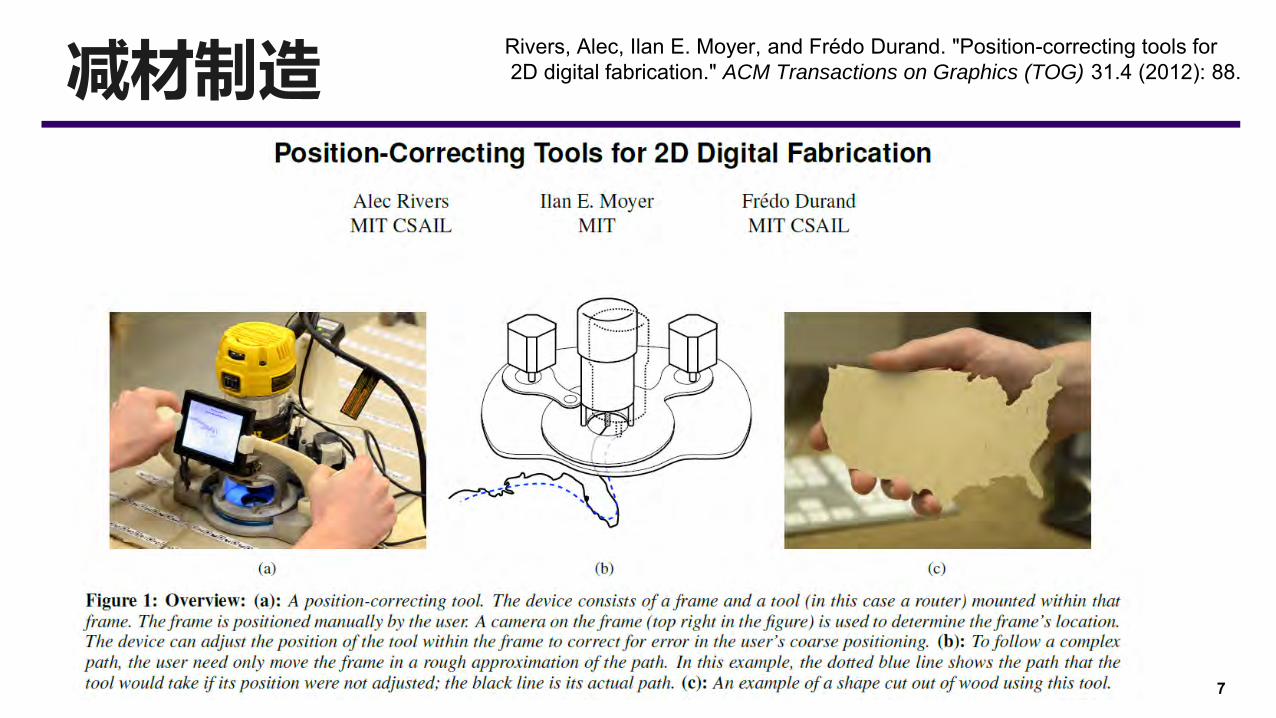
减材制造Rivers, Alec, Ilan E. Moyer, and Frédo Durand. "Position-correcting tools for2D digital fabrication." ACM Transactions on Graphics (TOG) 31.4 (2012): 88.
8
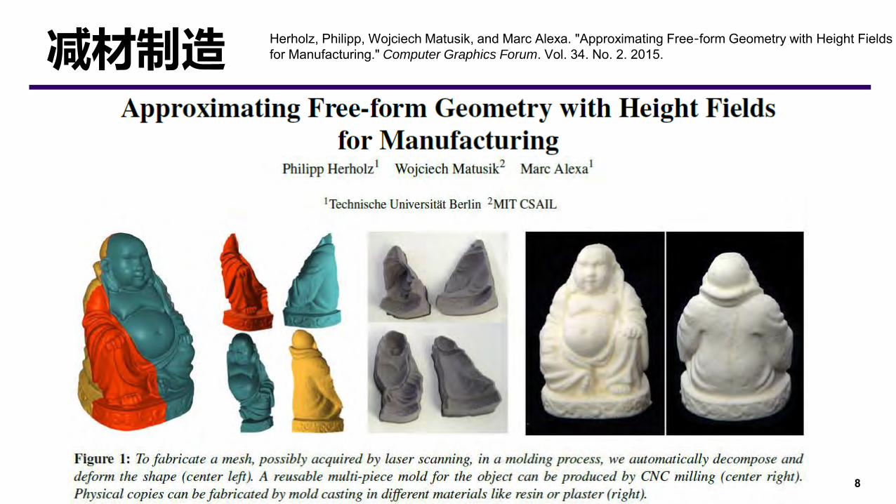
减材制造 Herholz, Philipp, Wojciech Matusik, and Marc Alexa. "Approximating Free‐form Geometry with Height Fieldsfor Manufacturing." Computer Graphics Forum. Vol. 34. No. 2. 2015.
9
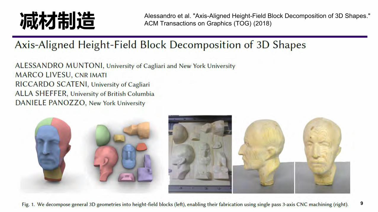
减材制造 Alessandro et al. "Axis-Aligned Height-Field Block Decomposition of 3D Shapes."ACM Transactions on Graphics (TOG) (2018)
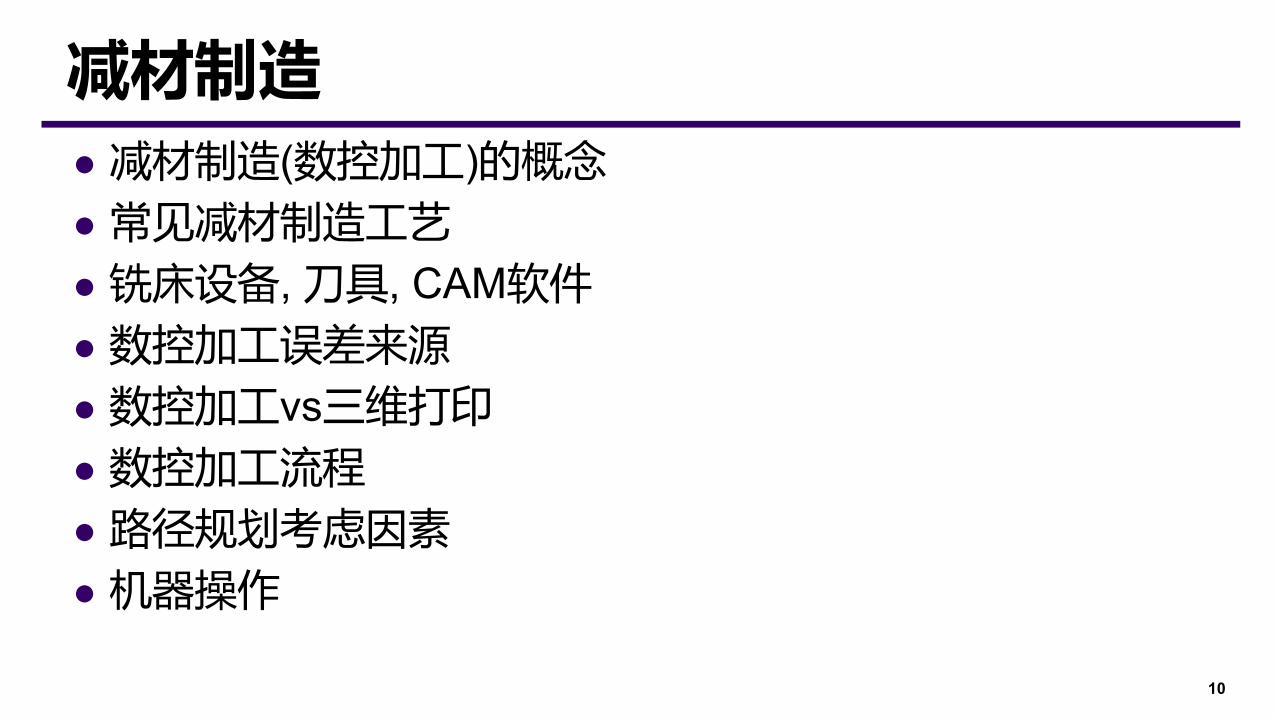
⚫ 减材制造(数控加工)的概念
⚫ 常见减材制造工艺
⚫ 铣床设备, 刀具, CAM软件
⚫ 数控加工误差来源
⚫ 数控加工vs三维打印
⚫ 数控加工流程
⚫ 路径规划考虑因素
⚫ 机器操作
10
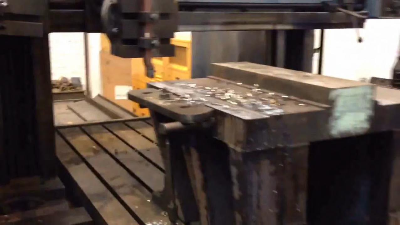
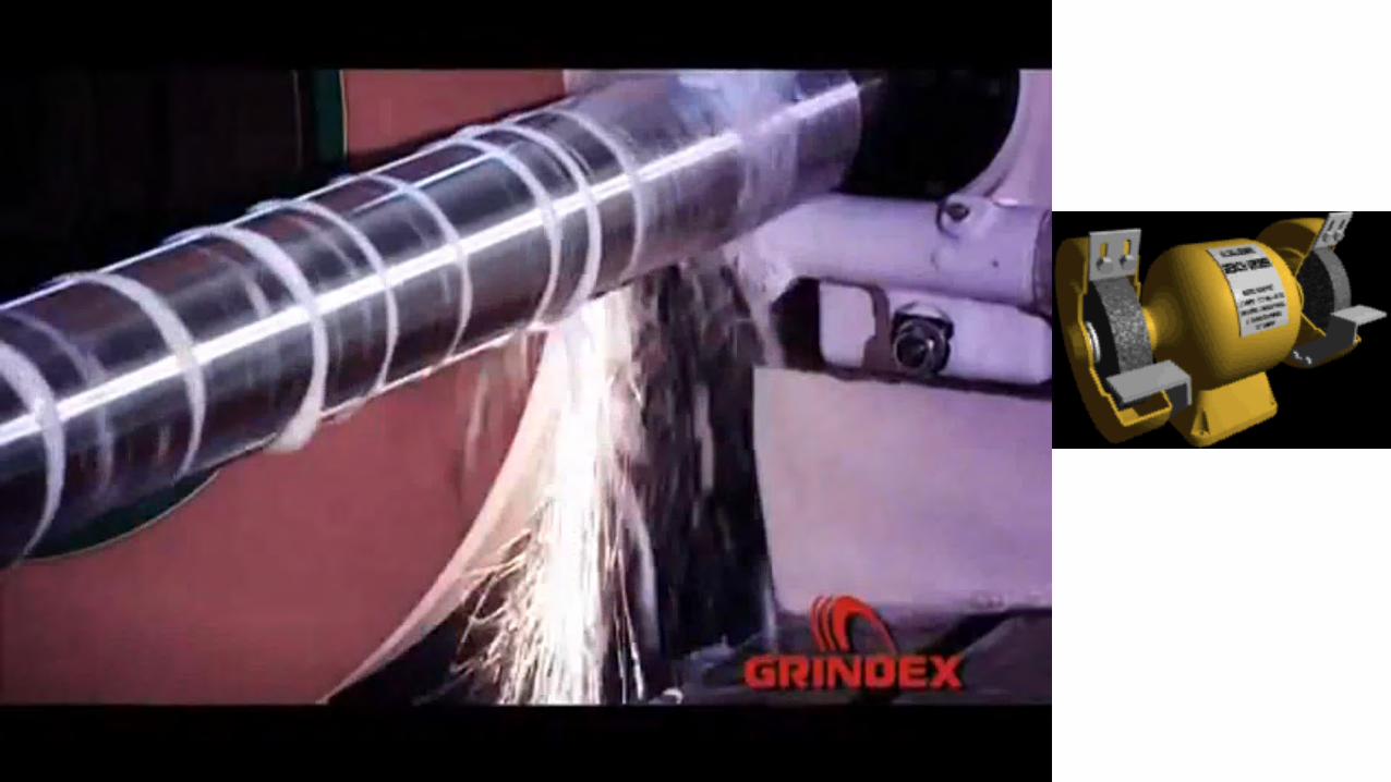
减材制造

⚫ 减材制造⚫ 相对于“增材制造”,将材料固定于设备上,通过刀具减去或去除材料的加工方式,最终成型为所需部件的工艺类型。
⚫ 数控加工(Computer Numerical Control, CNC)⚫ 通过编程,数控机床以无需手工干预的自动连续的方式去除余料,适合于大批量、形状复杂的零件;
⚫ 上世纪40年代,第一台手动控制机床诞生。
11
减材制造
http://www.ach-wisdom.com/h-col-121.html http://www.wisegeek.org/what-are-cnc-machines.htm

16
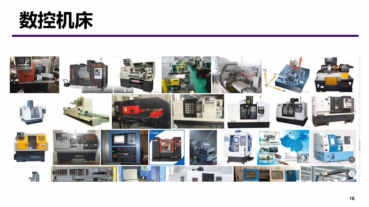
数控机床

⚫ 轴数:2,3,4,5,5+⚫ 电机:步进电机,伺服电机
⚫ 用途:雕刻机,大型机床17
数控机床
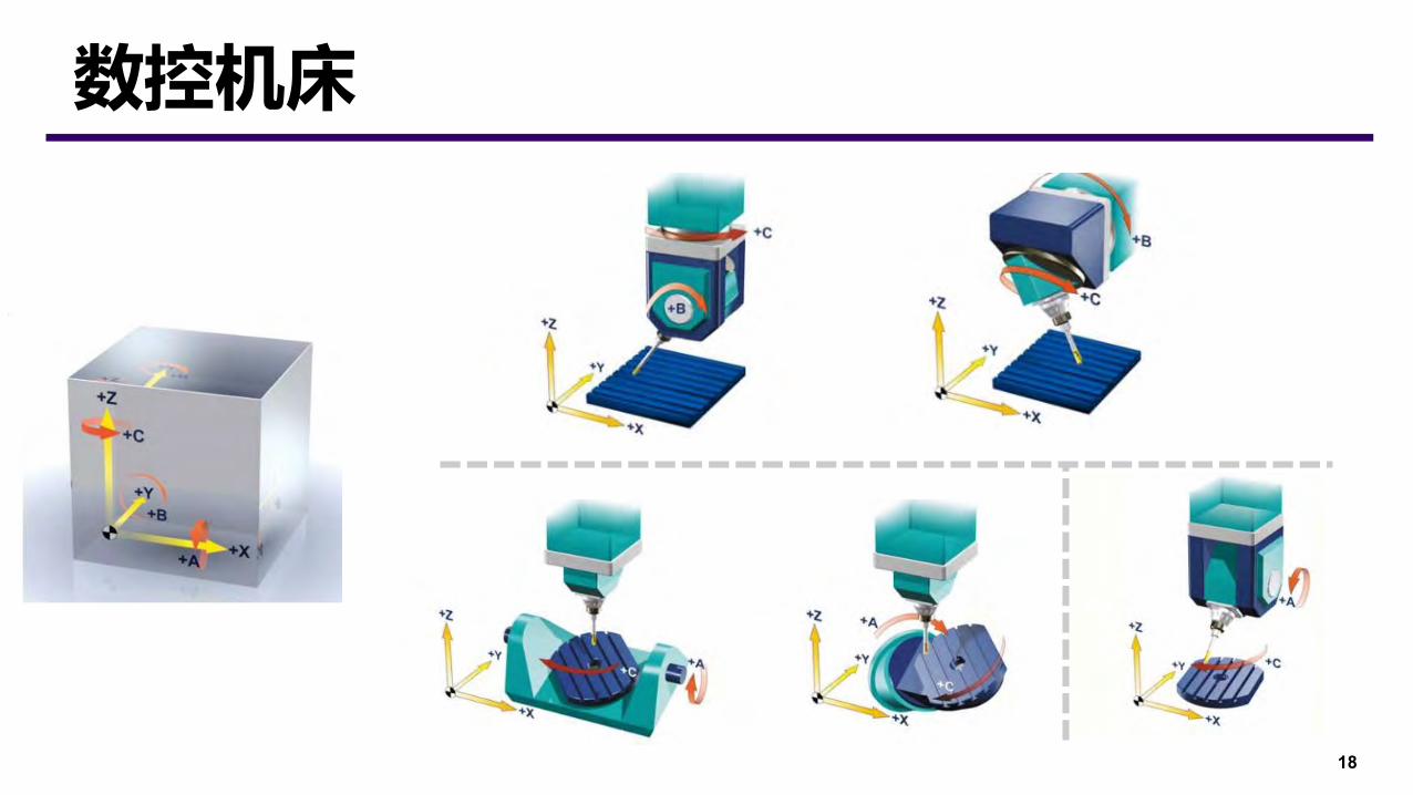
18
数控机床
19
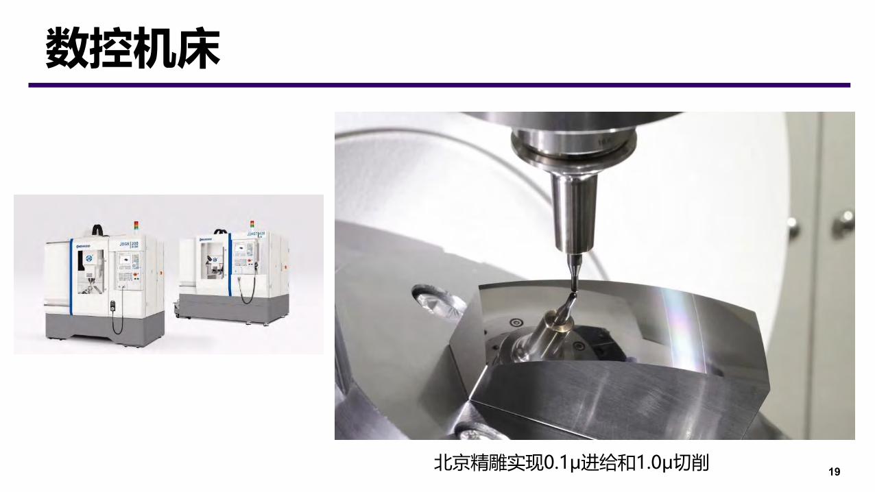
数控机床
北京精雕实现0.1μ进给和1.0μ切削

20
刀具
平底刀 尖刀 球头刀

⚫ 刀具磨损/变形/尺寸误差
⚫ 工件热变形和弹性变形误差
⚫ 机床运动误差
⚫ 编程中计算误差
⚫ 加工系统震动(振纹)⚫ 加工铣削温度变化
⚫ 切削力的变化
⚫ 残留应力
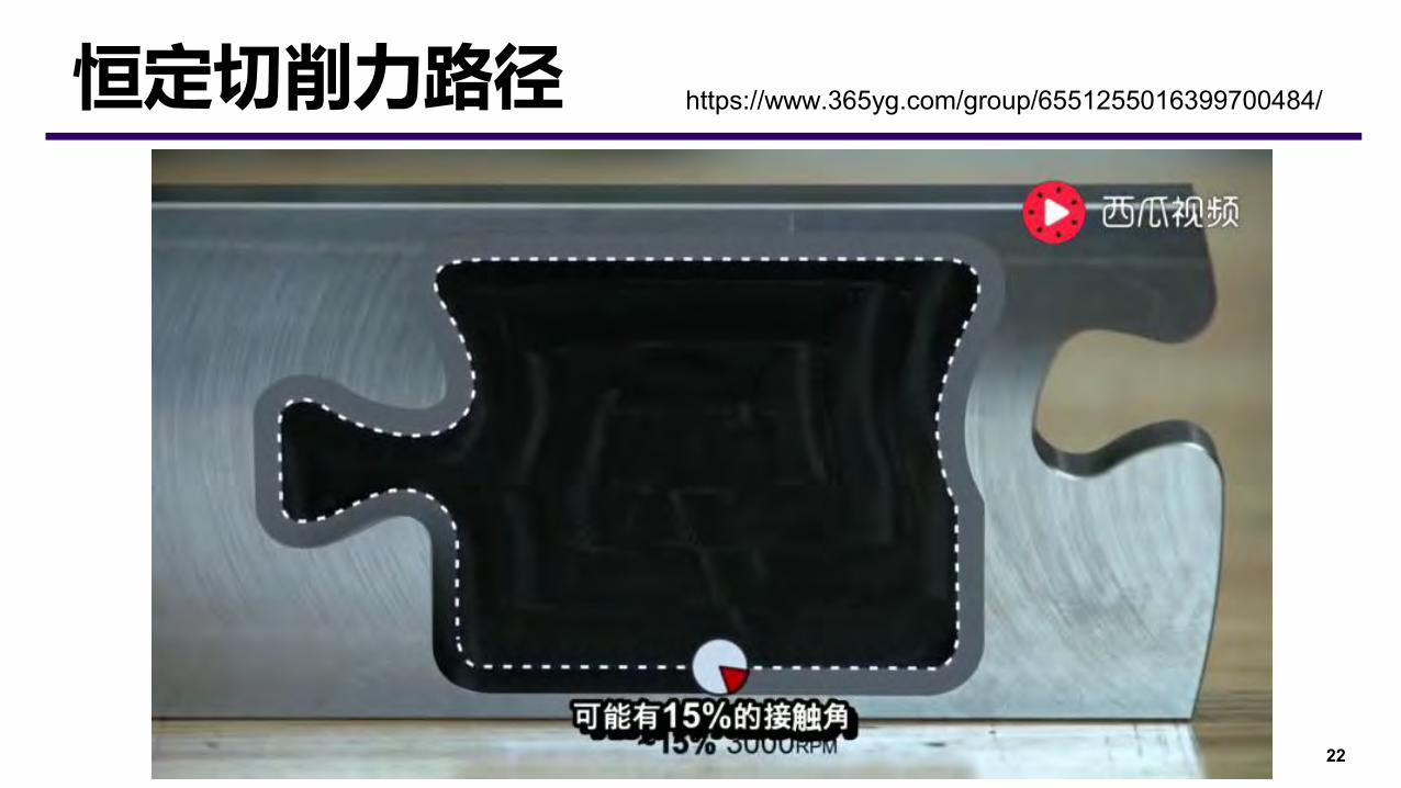
⚫ 刀具端点切削力为0⚫ 进给速度优化(恒定切削力)
21
误差因素
22
恒定切削力路径 https://www.365yg.com/group/6551255016399700484/
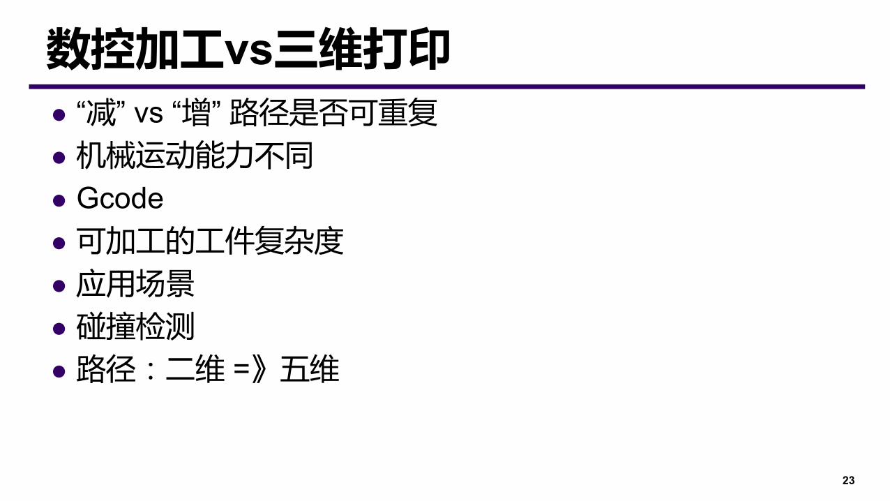
⚫ “减” vs “增” 路径是否可重复
⚫ 机械运动能力不同
⚫ Gcode⚫ 可加工的工件复杂度
⚫ 应用场景
⚫ 碰撞检测
⚫ 路径:二维 =》五维
23
数控加工vs三维打印
24
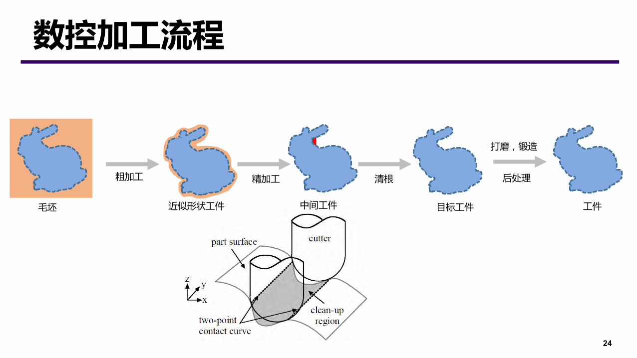
数控加工流程
毛坯 近似形状工件
粗加工
中间工件
精加工 清根
目标工件 工件
后处理
打磨,锻造
⚫ Process planning⚫ Setup planning⚫ Tool path planning⚫ Trajectory planning
25
规划流程
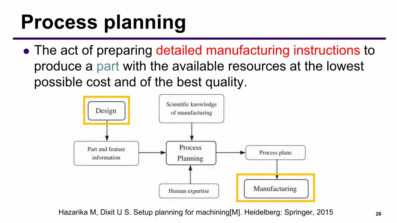
⚫ The act of preparing detailed manufacturing instructions to produce a part with the available resources at the lowest possible cost and of the best quality.
26
Process planning
Hazarika M, Dixit U S. Setup planning for machining[M]. Heidelberg: Springer, 2015

⚫ The act of preparing detailed manufacturing instructions to produce a part with the available resources at the lowest possible cost and of the best quality.⚫ Design interpretation⚫ Process selection and machine selection⚫ Setup planning⚫ Process parameters selection⚫ Cycle time estimation and scheduling⚫ Cost evaluation⚫ Documentation
27
Process planning
Hazarika M, Dixit U S. Setup planning for machining[M]. Heidelberg: Springer, 2015
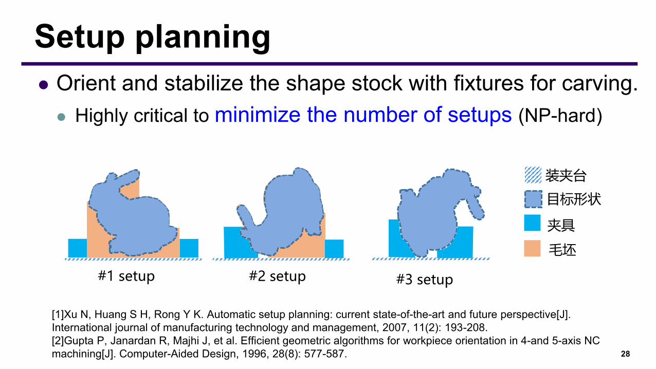
⚫ Orient and stabilize the shape stock with fixtures for carving.⚫ Highly critical to minimize the number of setups (NP-hard)
28
Setup planning
#1 setup #2 setup #3 setup
装夹台
目标形状
夹具
毛坯
[1]Xu N, Huang S H, Rong Y K. Automatic setup planning: current state-of-the-art and future perspective[J]. International journal of manufacturing technology and management, 2007, 11(2): 193-208.[2]Gupta P, Janardan R, Majhi J, et al. Efficient geometric algorithms for workpiece orientation in 4-and 5-axis NC machining[J]. Computer-Aided Design, 1996, 28(8): 577-587.

29
Setup planning—Related works
Prismatic parts(箱体工件)
Rotational parts(回转体工件)
30
Setup planning—Industry area
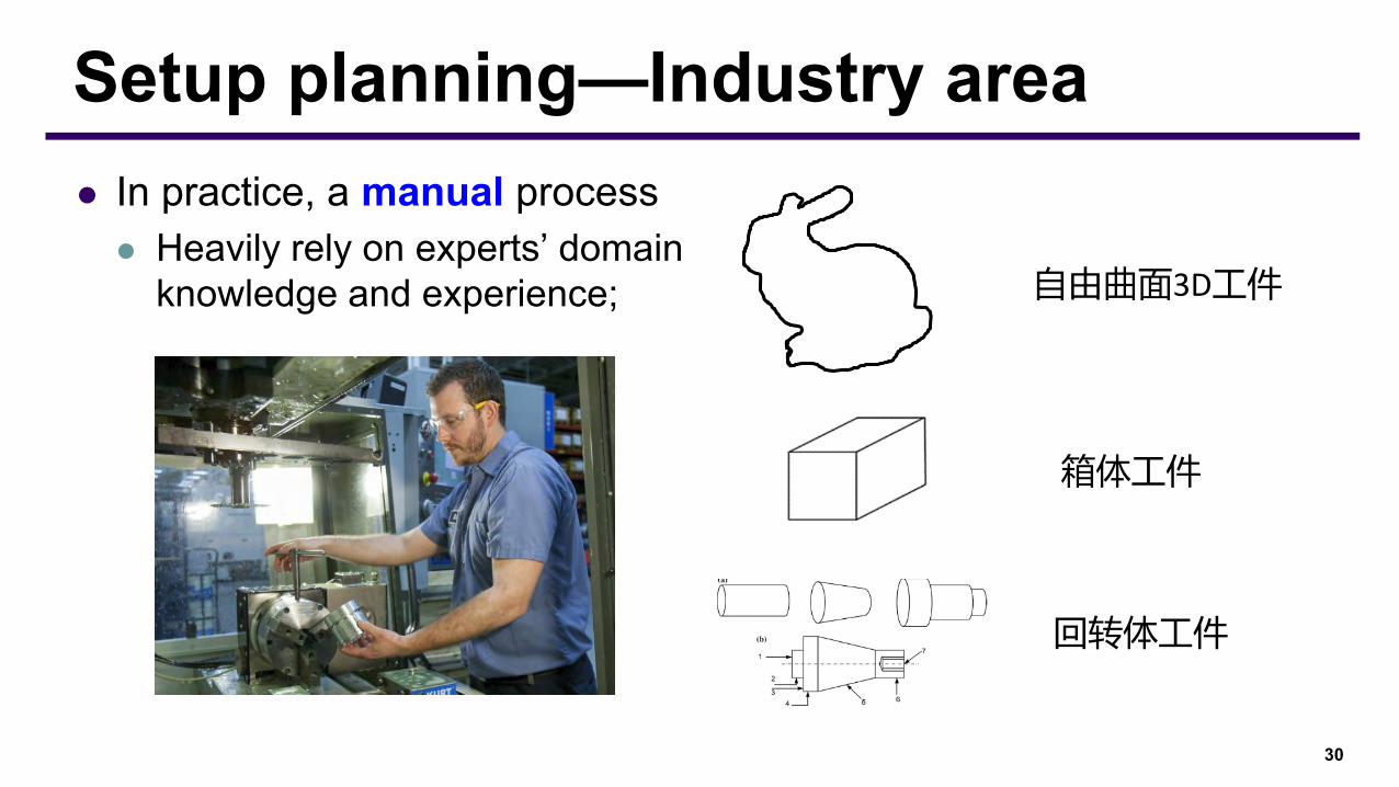
回转体工件
⚫ In practice, a manual process⚫ Heavily rely on experts’ domain
knowledge and experience; 自由曲面3D工件
箱体工件
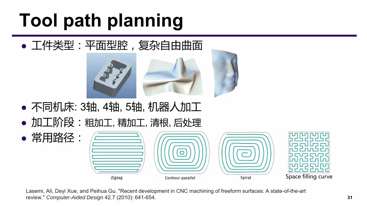
⚫ 工件类型:平面型腔,复杂自由曲面
⚫ 不同机床: 3轴, 4轴, 5轴, 机器人加工
⚫ 加工阶段:粗加工, 精加工, 清根, 后处理
⚫ 常用路径:
31
Tool path planning
Space filling curve
Lasemi, Ali, Deyi Xue, and Peihua Gu. "Recent development in CNC machining of freeform surfaces: A state-of-the-art review." Computer-Aided Design 42.7 (2010): 641-654.
⚫ 路径光顺性 》加工效率
⚫ 路径连续性 》撤刀次数 》加工效率 +加工精度
⚫ 路径长度 》加工效率
⚫ 刀具姿态 》刀头负载均衡 》刀具寿命
》去材料率 》加工效率+加工精度
》刀具干涉
⚫ 残留高度均匀性 》加工效率 + 加工精度
32
Tool path planning
33
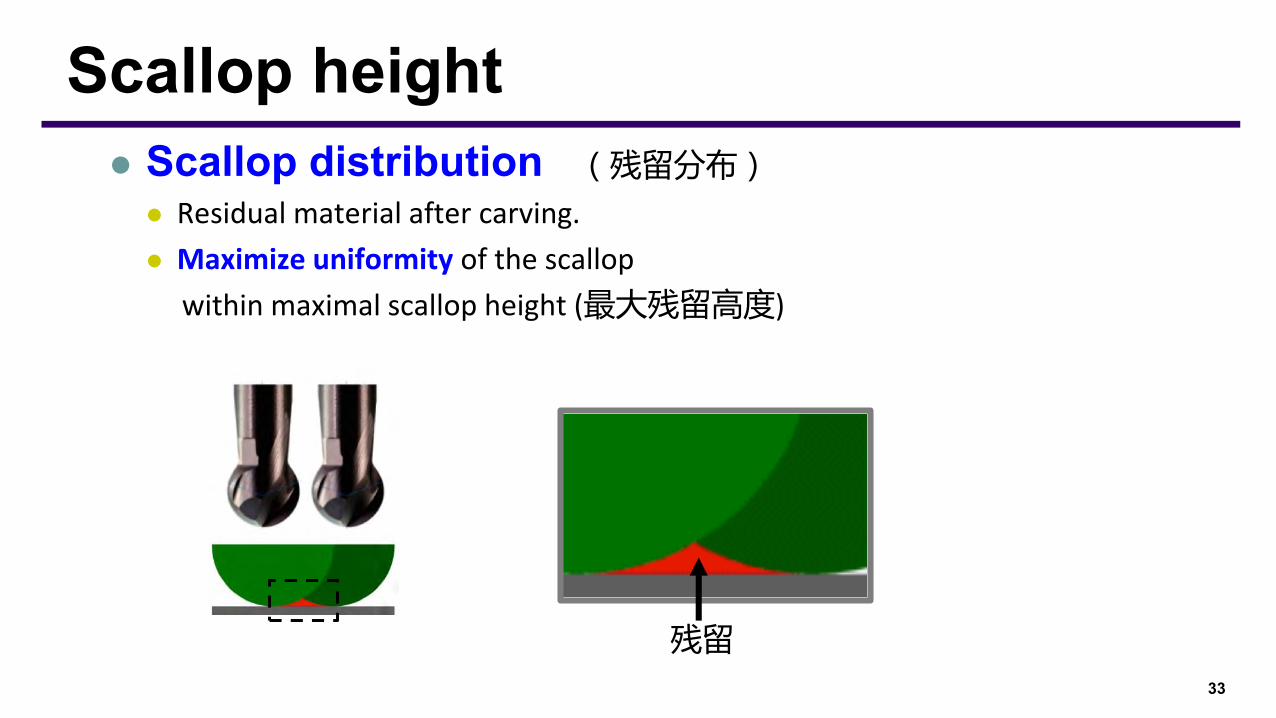
Scallop height⚫ Scallop distribution (残留分布)
⚫ Residual material after carving.
⚫ Maximize uniformity of the scallop
within maximal scallop height (最大残留高度)
残留

34
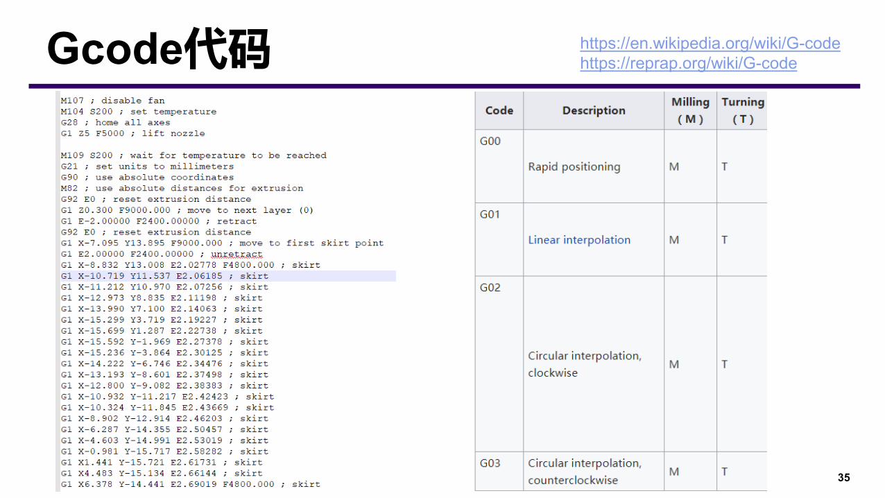
CC/CL⚫ Cutter Contact Point刀触点
⚫ Cutter Location Point 刀位点
35
Gcode代码 https://en.wikipedia.org/wiki/G-codehttps://reprap.org/wiki/G-code
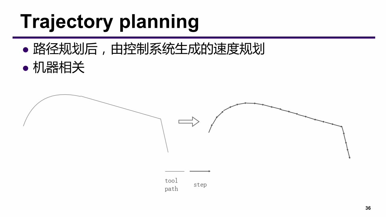
⚫ 路径规划后,由控制系统生成的速度规划
⚫ 机器相关
36
Trajectory planning
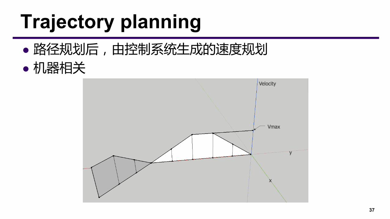
⚫ 路径规划后,由控制系统生成的速度规划
⚫ 机器相关
37
Trajectory planning
⚫ 常用CAM软件
UG、Pro/Engineer、MasterCamCAXA ME、CATIA、Cimatron、PowerMill 、 Tebis,Delcam,Edgecam
⚫ 模拟:VERICUT, OpenRAVE⚫ CAM开发: 接口,OpenCascade, AnyCAD
⚫ CNC term:http://www.hsmworks.com/docs/cncbook/en/https://www.cnccookbook.com/cnc-dictionary/
38
CAM
39
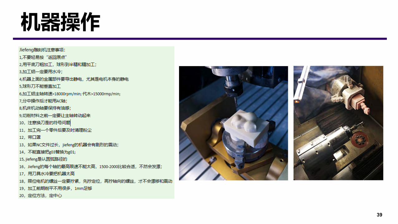
机器操作
Connected Fermat Spirals for Layered Fabrication
Haisen Zhao1, Fanglin Gu1, Qi-Xing Huang2, Jorge Garcia3, Yong Chen4, Changhe Tu1, Bedrich Benes3, Hao (Richard) Zhang5, Daniel Cohen-Or6, Baoquan Chen1
1Shandong University 2TTI Chicago 3Purdue University 4USC
5Simon Fraser University 6Tel-Aviv University
ACM SIGGRAPH 2016
41
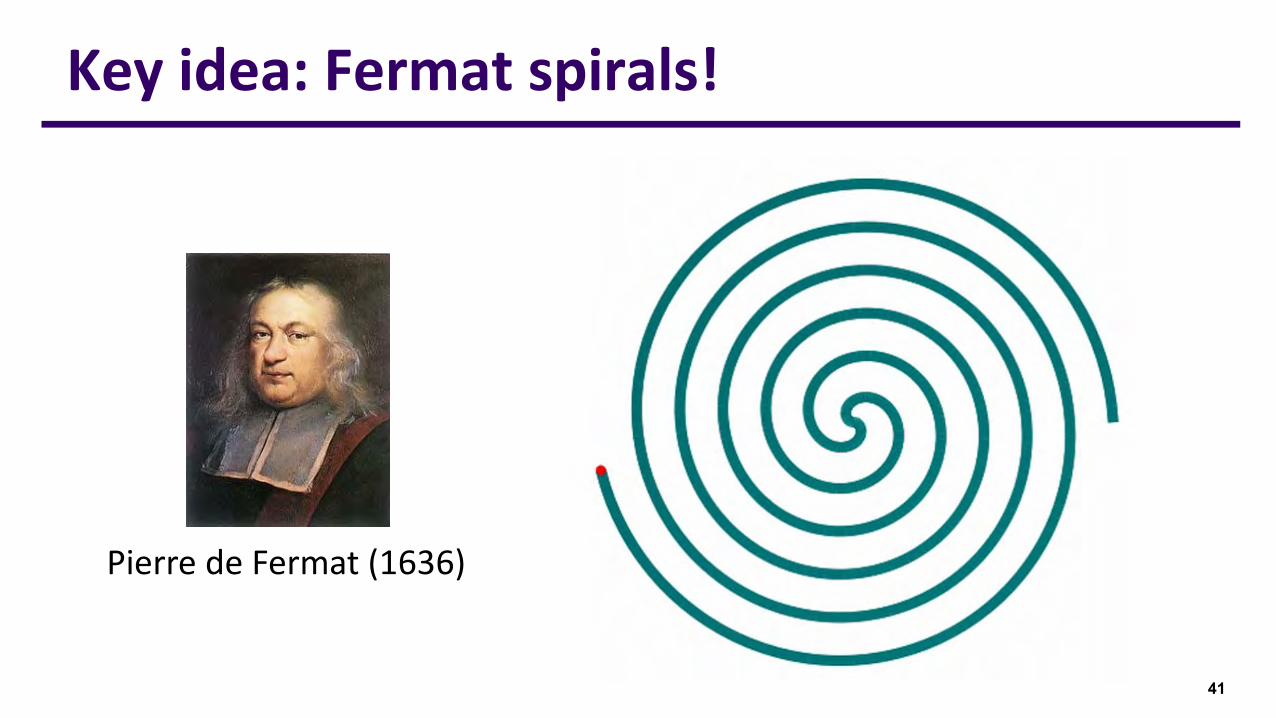
Key idea: Fermat spirals!
Pierre de Fermat (1636)

start pointend point
Fermat spiral: compelling properties
⚫ Similarities to spiral and CPPs
⚫ Conform to surface boundaries
⚫ Less sharp turns than zigzag
⚫ Continuity for simple shapes
⚫ New: start & end on boundary
⚫ Key observation: can place start & end points freely along boundary
⚫ Allows connection of all Fermat spirals to achieve global continuity
42start point end point
start pointend point
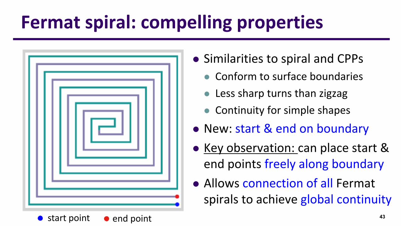
Fermat spiral: compelling properties
⚫ Similarities to spiral and CPPs
⚫ Conform to surface boundaries
⚫ Less sharp turns than zigzag
⚫ Continuity for simple shapes
⚫ New: start & end on boundary
⚫ Key observation: can place start & end points freely along boundary
⚫ Allows connection of all Fermat spirals to achieve global continuity
43start point end point
start pointend point
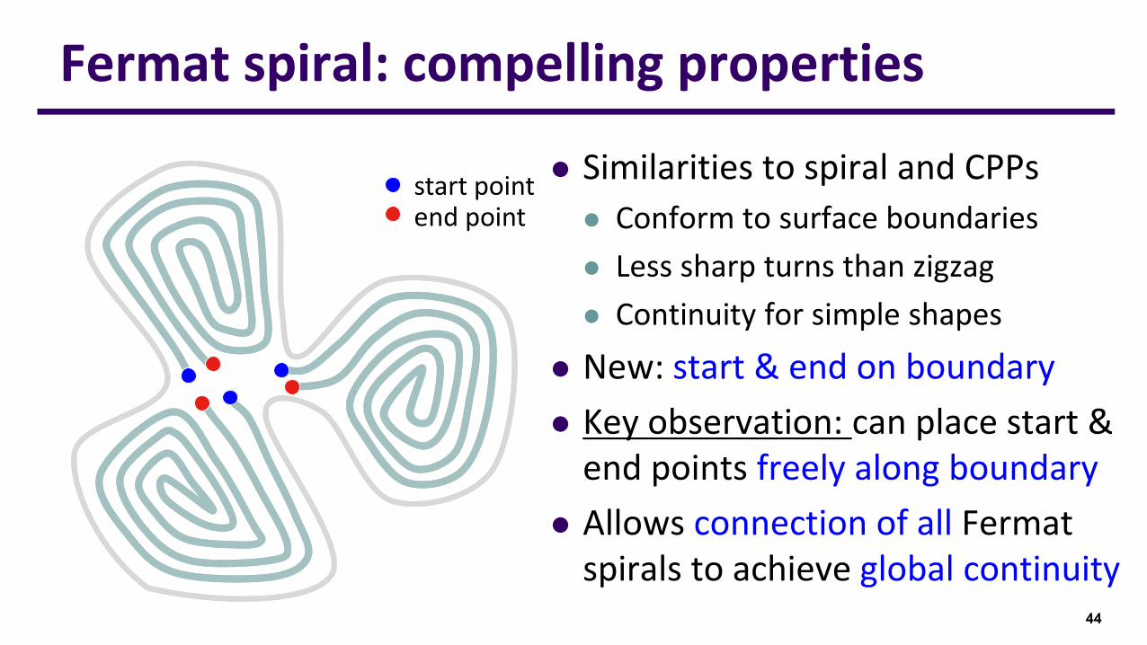
Fermat spiral: compelling properties
⚫ Similarities to spiral and CPPs
⚫ Conform to surface boundaries
⚫ Less sharp turns than zigzag
⚫ Continuity for simple shapes
⚫ New: start & end on boundary
⚫ Key observation: can place start & end points freely along boundary
⚫ Allows connection of all Fermat spirals to achieve global continuity
44

start pointend point
Fermat spiral: compelling properties
⚫ Similarities to spiral and CPPs
⚫ Conform to surface boundaries
⚫ Less sharp turns than zigzag
⚫ Continuity for simple shapes
⚫ New: start & end on boundary
⚫ Key observation: can place start & end points freely along boundary
⚫ Allows connection of all Fermat spirals to achieve global continuity
45
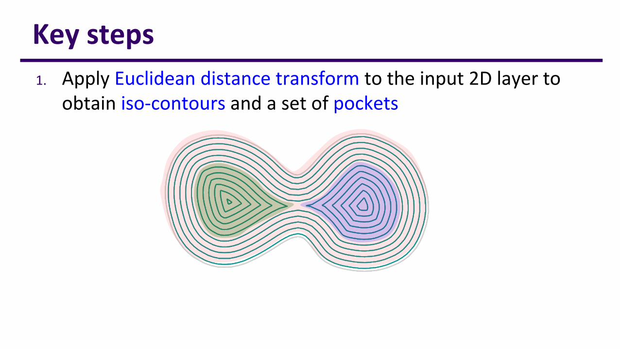
1. Apply Euclidean distance transform to the input 2D layer to obtain iso-contours and a set of pockets
Key steps

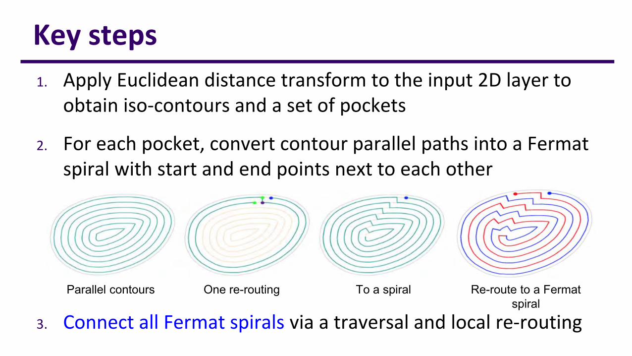
1. Apply Euclidean distance transform to the input 2D layer to obtain iso-contours and a set of pockets
2. For each pocket, convert contour parallel paths into a Fermat spiral with start and end points next to each other
Key steps
Parallel contours One re-routing To a spiral Re-route to a Fermat spiral
1. Apply Euclidean distance transform to the input 2D layer to obtain iso-contours and a set of pockets
2. For each pocket, convert contour parallel paths into a Fermat spiral with start and end points next to each other
3. Connect all Fermat spirals via a traversal and local re-routing
Key steps
Parallel contours One re-routing To a spiral Re-route to a Fermat spiral
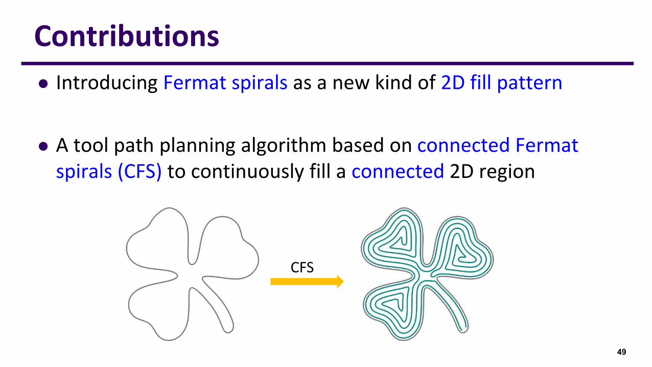
⚫ Introducing Fermat spirals as a new kind of 2D fill pattern
⚫ A tool path planning algorithm based on connected Fermat spirals (CFS) to continuously fill a connected 2D region
49
Contributions
CFS

50
Connected Fermat spirals
⚫ Global continuity ⚫ Long and low-curvature paths

Sub-regionsFermat spiralsConnected Fermat Spirals2D region
51
Overview
Iso-contours
Optimized CFSConnected Fermat Spirals
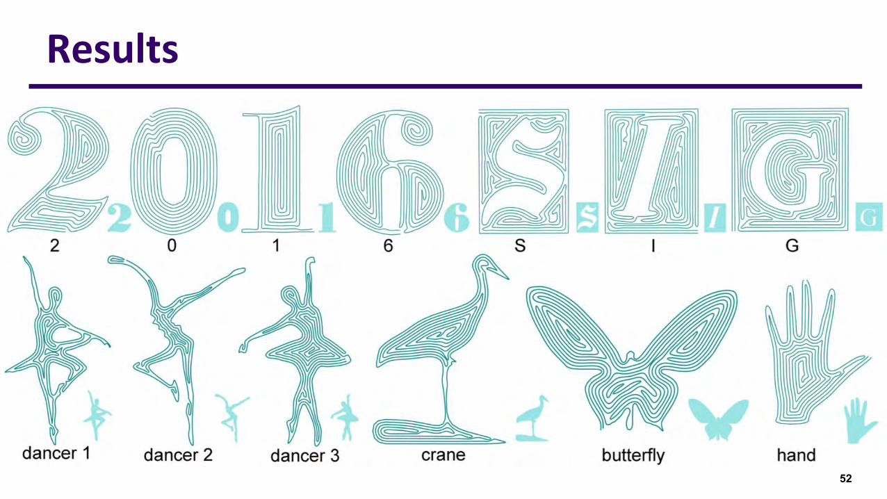
52
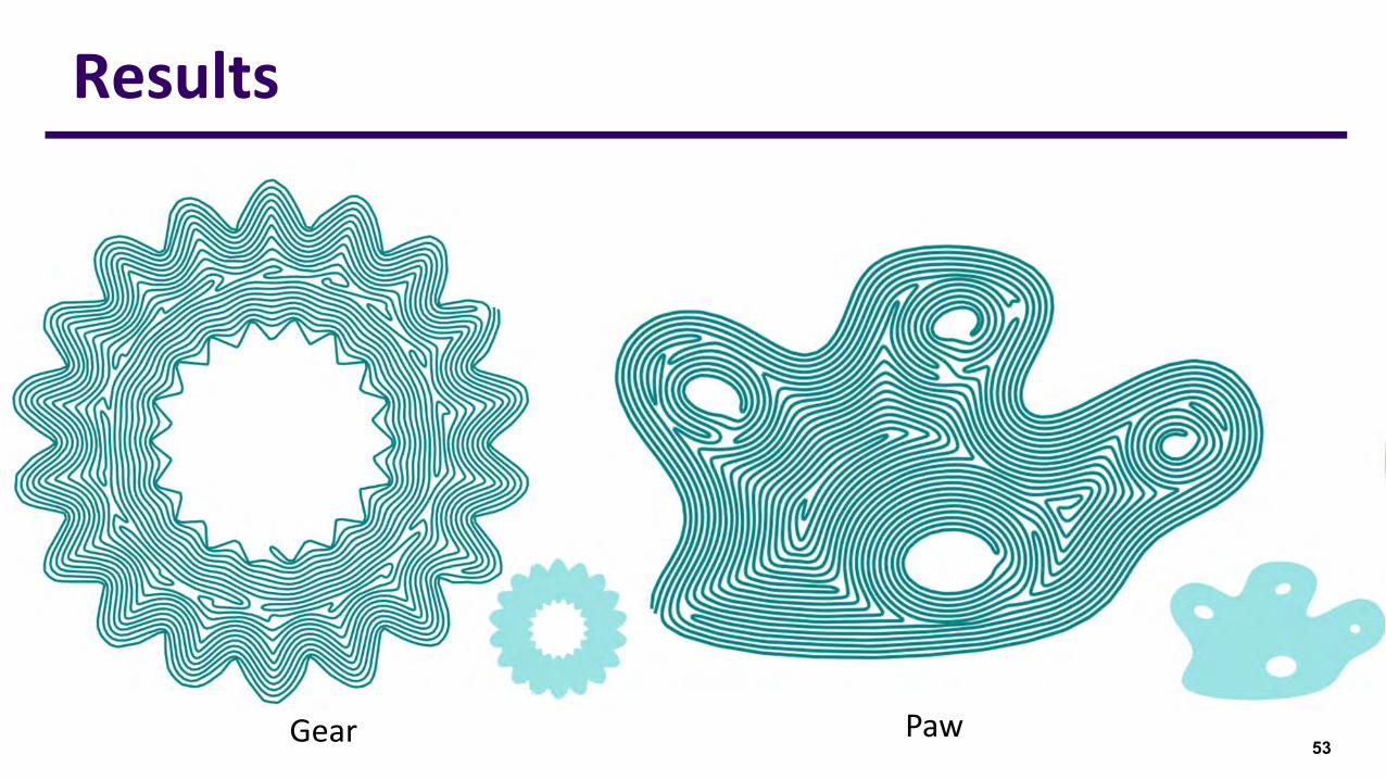
Results
53
Results
Gear Paw
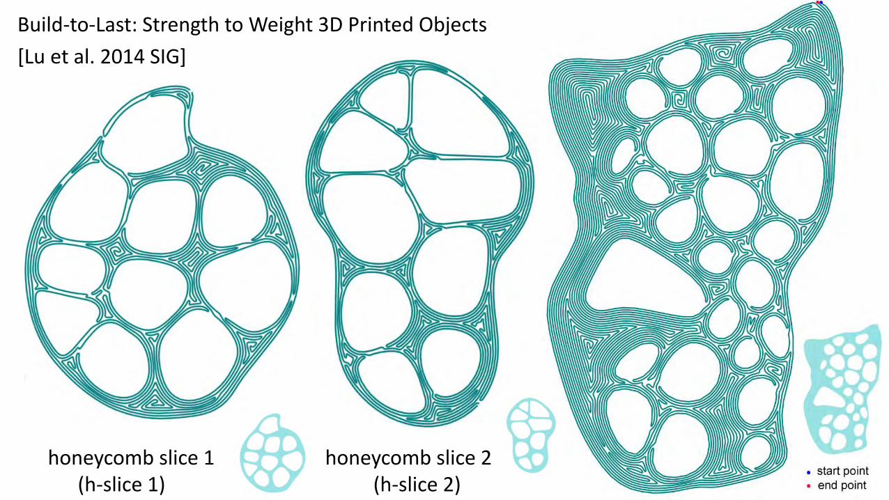
Build-to-Last: Strength to Weight 3D Printed Objects
[Lu et al. 2014 SIG]
honeycomb slice 1(h-slice 1)
honeycomb slice 2(h-slice 2)
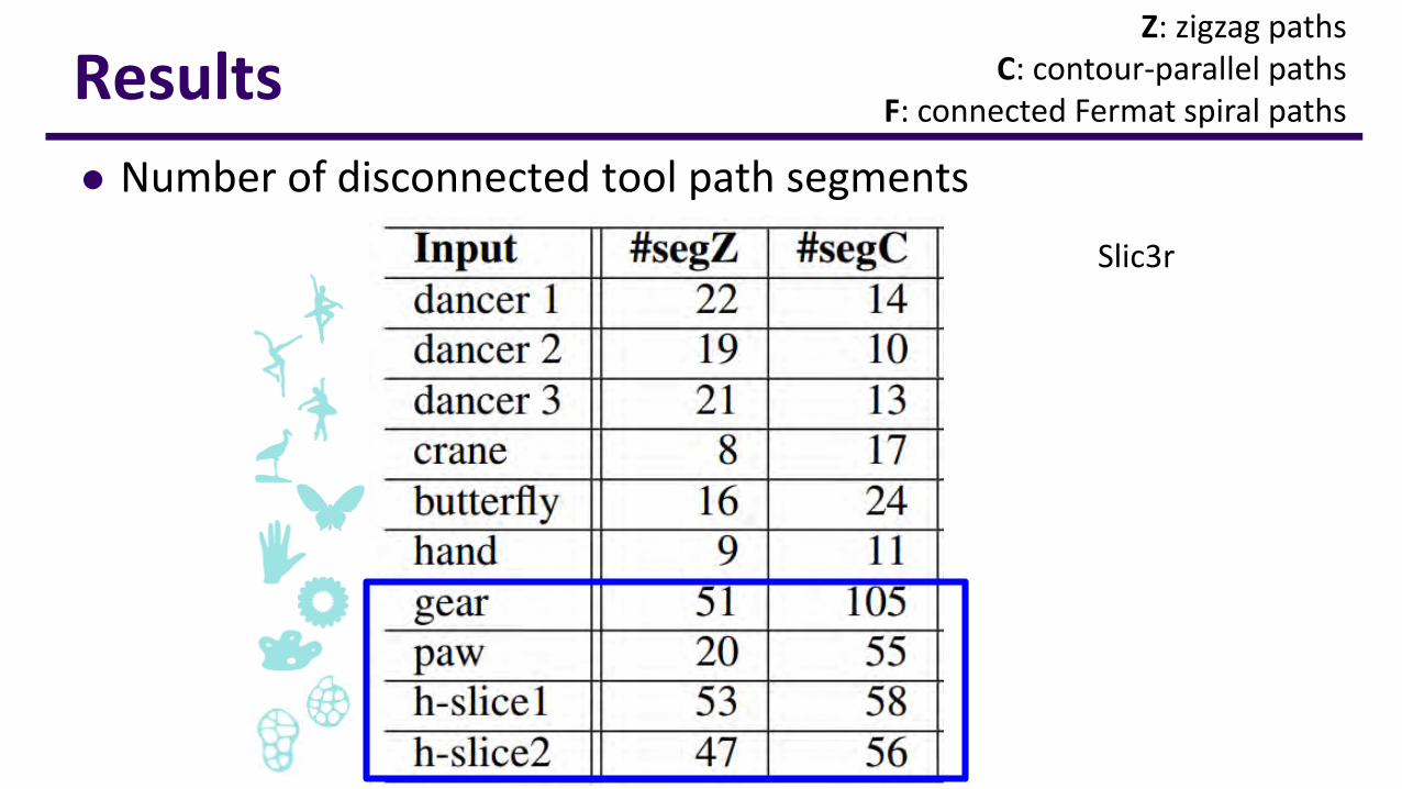
Z: zigzag pathsC: contour-parallel paths
F: connected Fermat spiral pathsResults
⚫ Number of disconnected tool path segments
Slic3r
Results
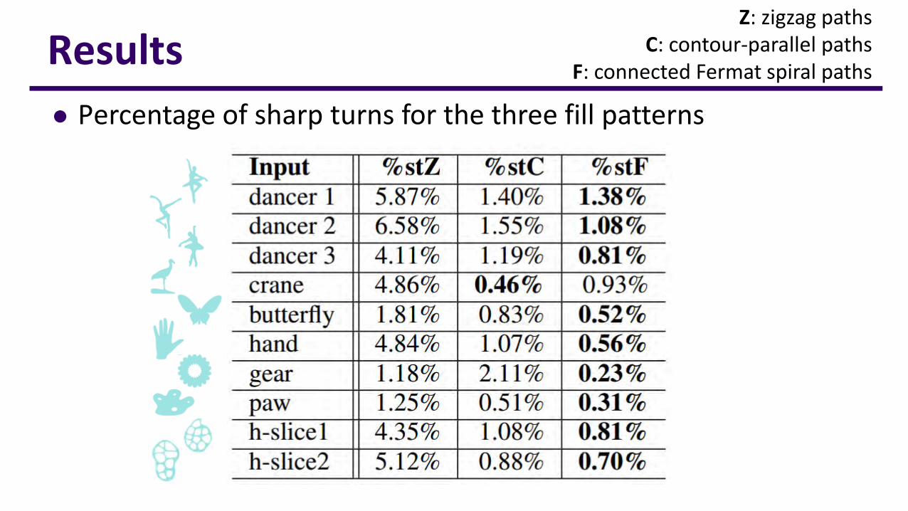
⚫ Percentage of sharp turns for the three fill patterns
Z: zigzag pathsC: contour-parallel paths
F: connected Fermat spiral paths
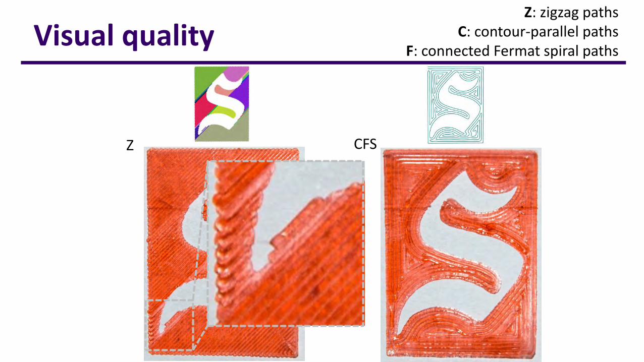
Visual qualityZ: zigzag paths
C: contour-parallel pathsF: connected Fermat spiral paths
Z CFS
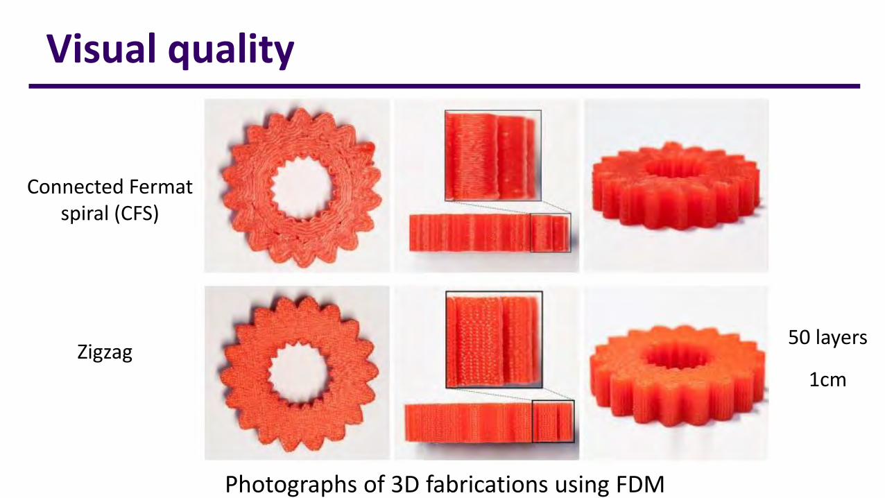
Visual quality
Photographs of 3D fabrications using FDM
Zigzag50 layers
1cm
Connected Fermat spiral (CFS)
59
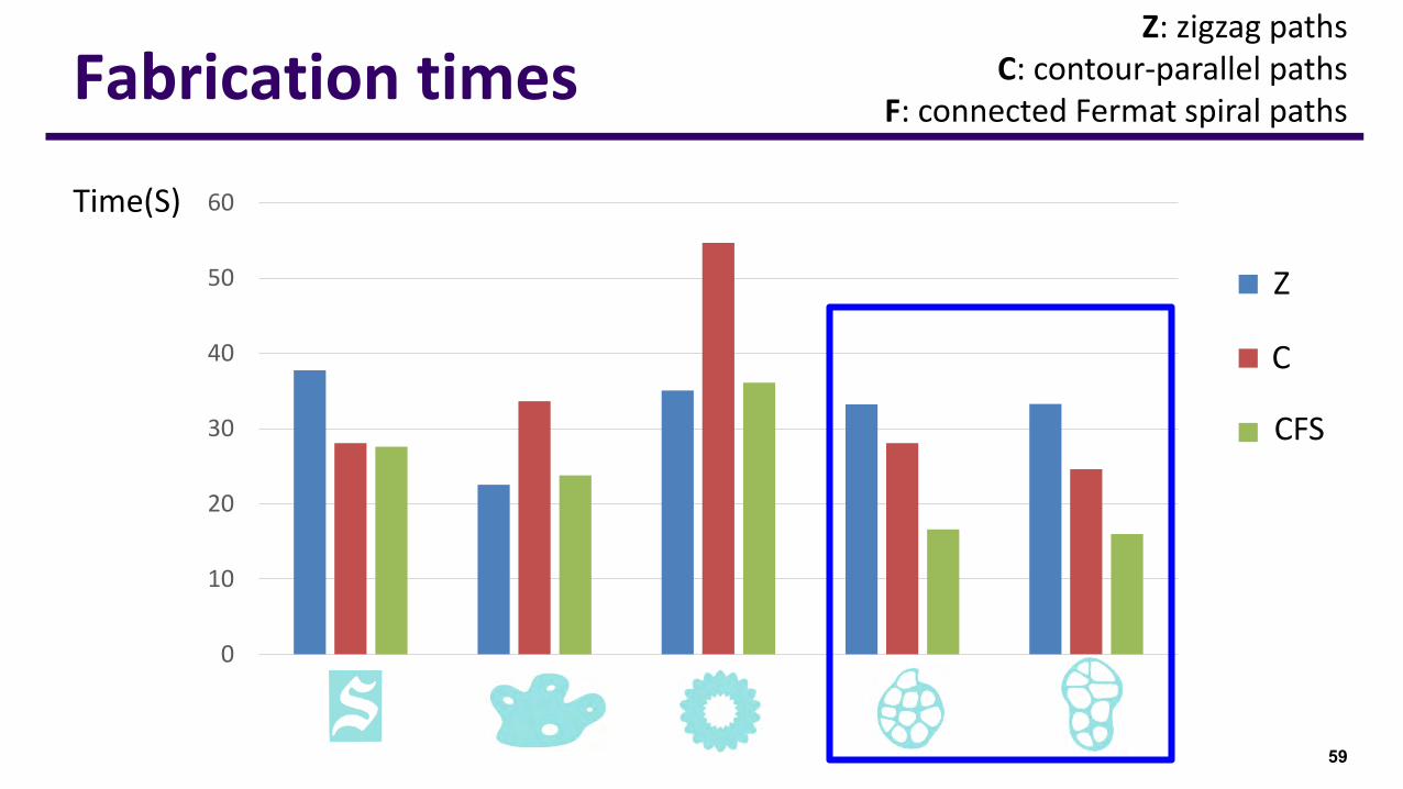
Fabrication times
Z
C
Time(S)
CFS
Z: zigzag pathsC: contour-parallel paths
F: connected Fermat spiral paths
0
10
20
30
40
50
60
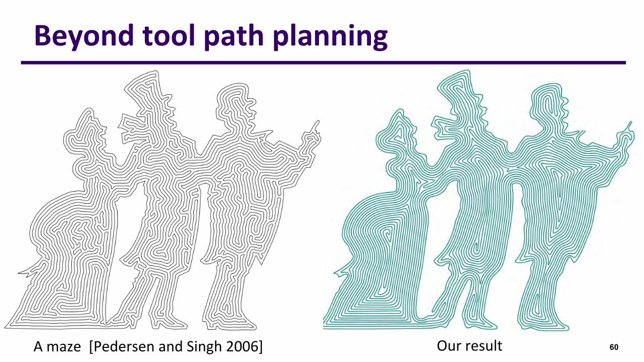
60Our resultA maze [Pedersen and Singh 2006]
Beyond tool path planning
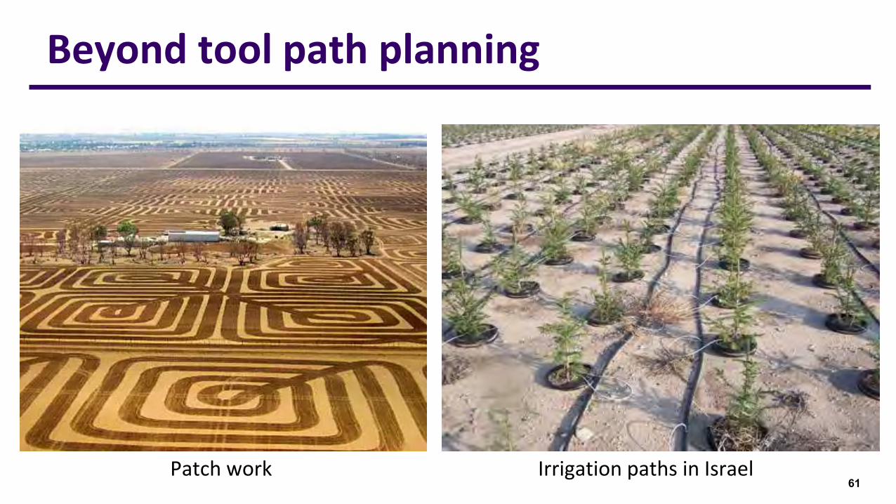
61Patch work
Beyond tool path planning
Irrigation paths in Israel
DSCarver: Decompose-and-Spiral-Carve for Subtractive Manufacturing
Haisen Zhao1, Hao (Richard) Zhang2, Shiqing Xin1, Yuanmin Deng1, Changhe Tu1, Wenping Wang3, Daniel Cohen-Or4, Baoquan Chen1,5
1Shandong University 2Simon Fraser University 3Hong Kong University
4Tel-Aviv University 5Peking University
ACM SIGGRAPH 2018
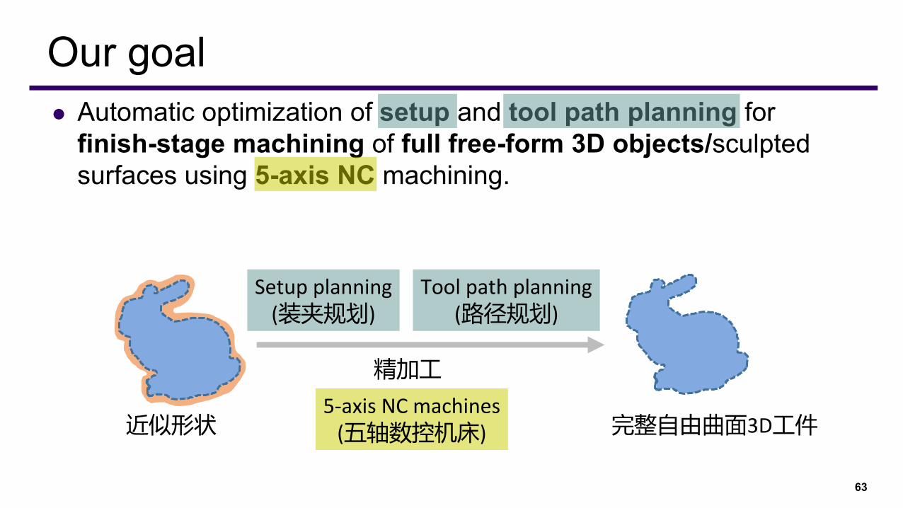
⚫ Automatic optimization of setup and tool path planning for finish-stage machining of full free-form 3D objects/sculpted surfaces using 5-axis NC machining.
63
Our goal
近似形状 完整自由曲面3D工件
精加工
Setup planning(装夹规划)
Tool path planning(路径规划)
5-axis NC machines(五轴数控机床)
64
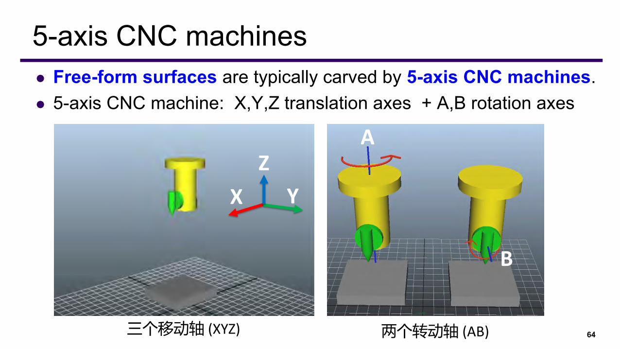
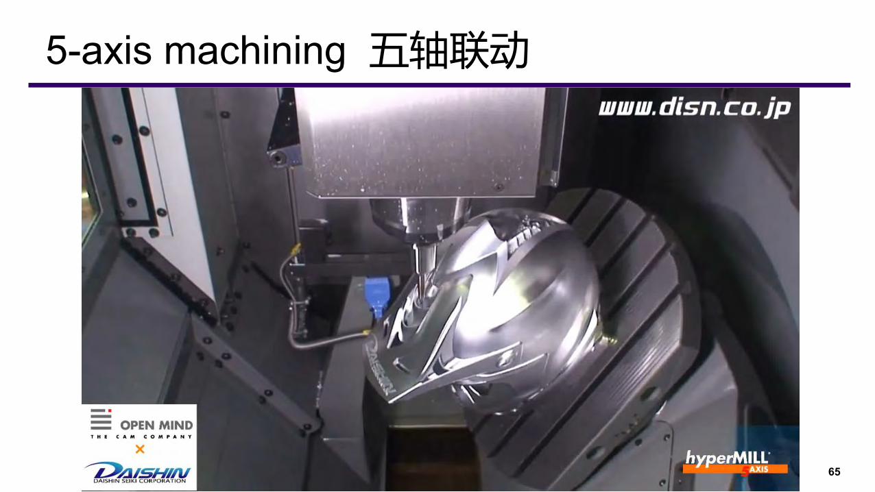
5-axis CNC machines⚫ Free-form surfaces are typically carved by 5-axis CNC machines.⚫ 5-axis CNC machine: X,Y,Z translation axes + A,B rotation axes
三个移动轴 (XYZ) 两个转动轴 (AB)
A
B
Z
X Y
65
5-axis machining 五轴联动
66
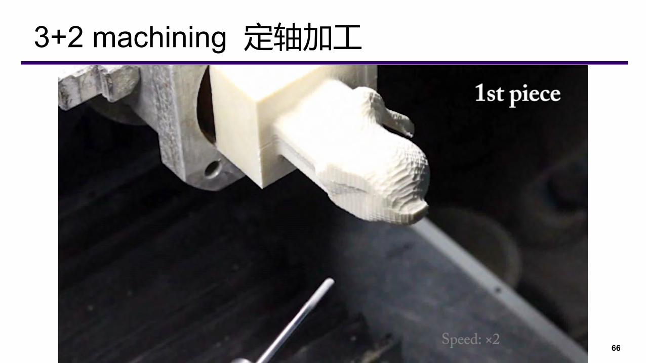
3+2 machining 定轴加工

⚫ 3+2 machining: common used
⚫ Less programming work (路径易于编程)⚫ Greater stiffness (轴体刚度更好)⚫ Longer tool life (刀具寿命更长)⚫ Higher surface quality (切削表面质量好)⚫ Higher machining efficient (加工效率高)
67
3+2 machining vs 5-axis machining
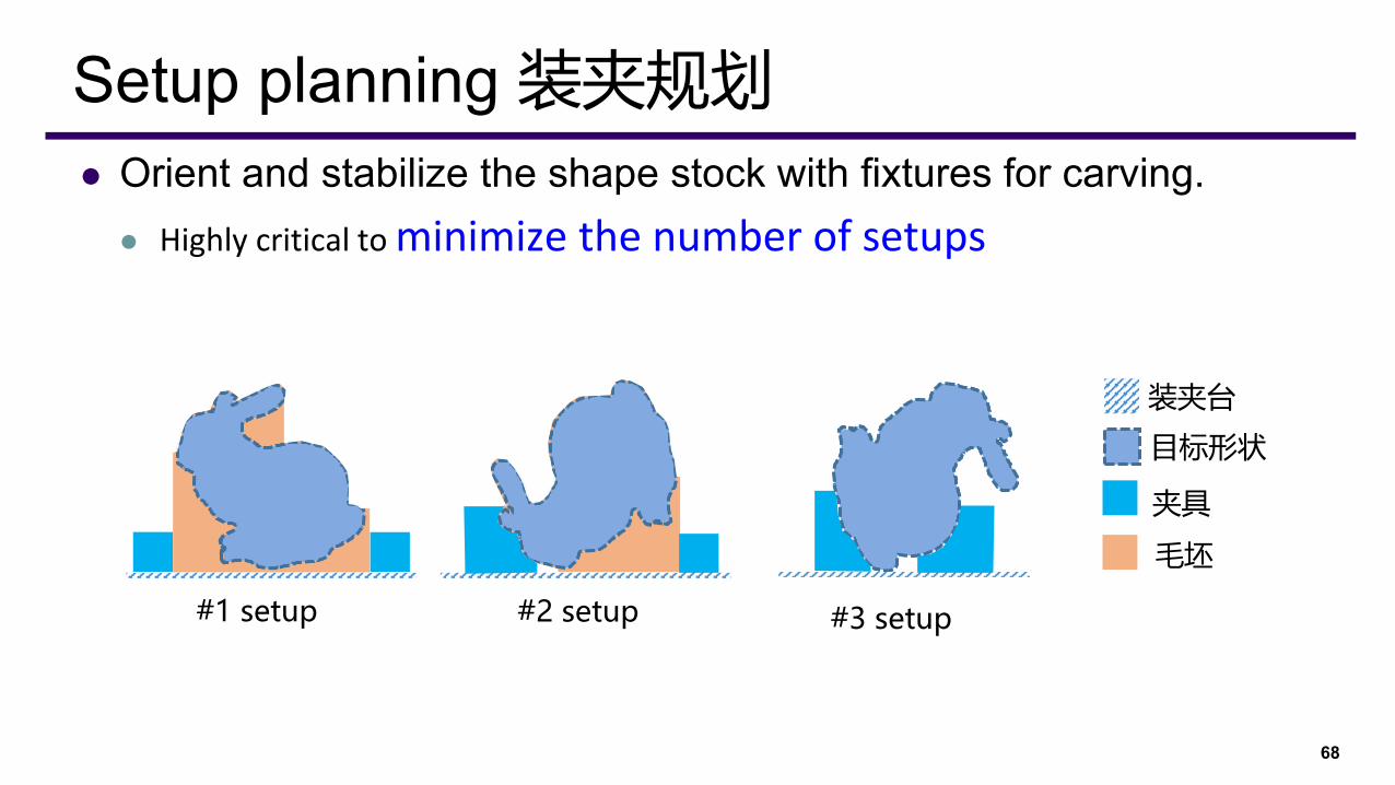
⚫ Orient and stabilize the shape stock with fixtures for carving.⚫ Highly critical to minimize the number of setups
68
Setup planning 装夹规划
#1 setup #2 setup #3 setup
装夹台
目标形状
夹具
毛坯

69
Setup planning—Related works
Prismatic parts(箱体工件)
Rotational parts(回转体工件)

70
Setup planning—Industry area
回转体工件
⚫ In practice, a manual process⚫ Heavily rely on experts’ domain
knowledge and experience; 自由曲面3D工件
箱体工件
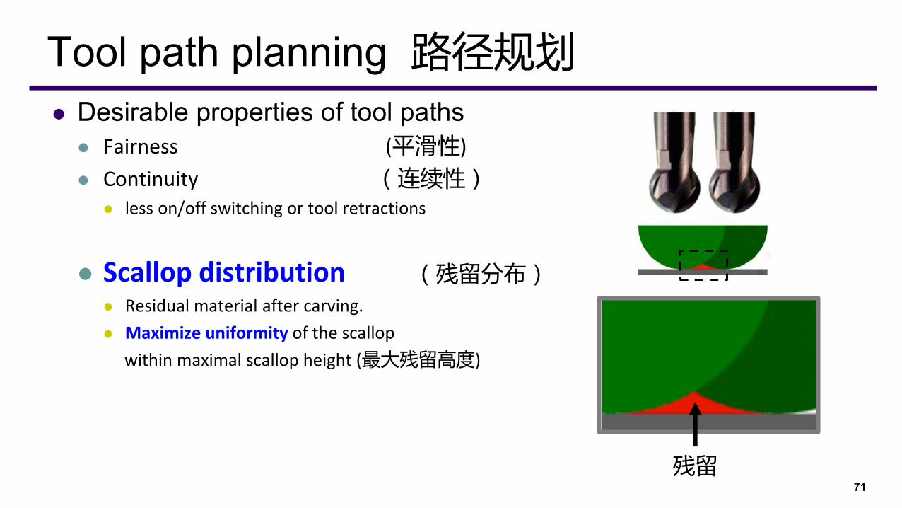
⚫ Desirable properties of tool paths⚫ Fairness (平滑性)
⚫ Continuity (连续性)⚫ less on/off switching or tool retractions
⚫ Scallop distribution (残留分布)⚫ Residual material after carving.
⚫ Maximize uniformity of the scallop
within maximal scallop height (最大残留高度)
71
Tool path planning 路径规划
残留

Fermat spiral to CNC
Connected Fermat spirals[Zhao et al. SIG 2016]
⚫ Global continuity ⚫ Long and low-curvature paths
15
2D – 3D
Scallop distribution
Connected ISO-scallop Fermat spirals
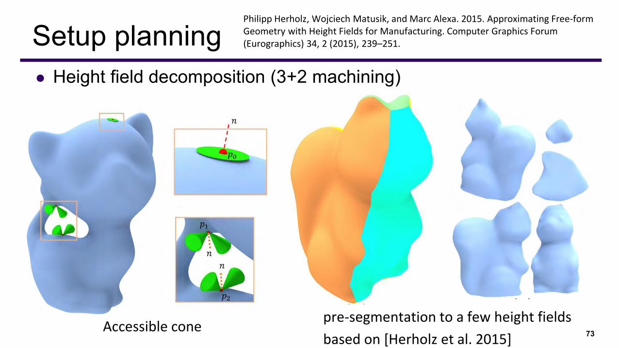
⚫ Height field decomposition (3+2 machining)
73
Setup planning
Accessible conepre-segmentation to a few height fields
based on [Herholz et al. 2015]
Philipp Herholz, Wojciech Matusik, and Marc Alexa. 2015. Approximating Free-form Geometry with Height Fields for Manufacturing. Computer Graphics Forum (Eurographics) 34, 2 (2015), 239–251.
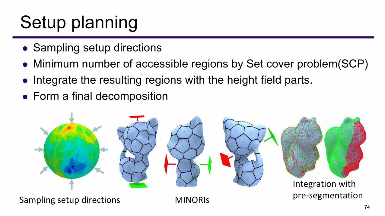
74
Setup planning⚫ Sampling setup directions⚫ Minimum number of accessible regions by Set cover problem(SCP)⚫ Integrate the resulting regions with the height field parts.⚫ Form a final decomposition
Sampling setup directions MINORIs
Integration with pre-segmentation
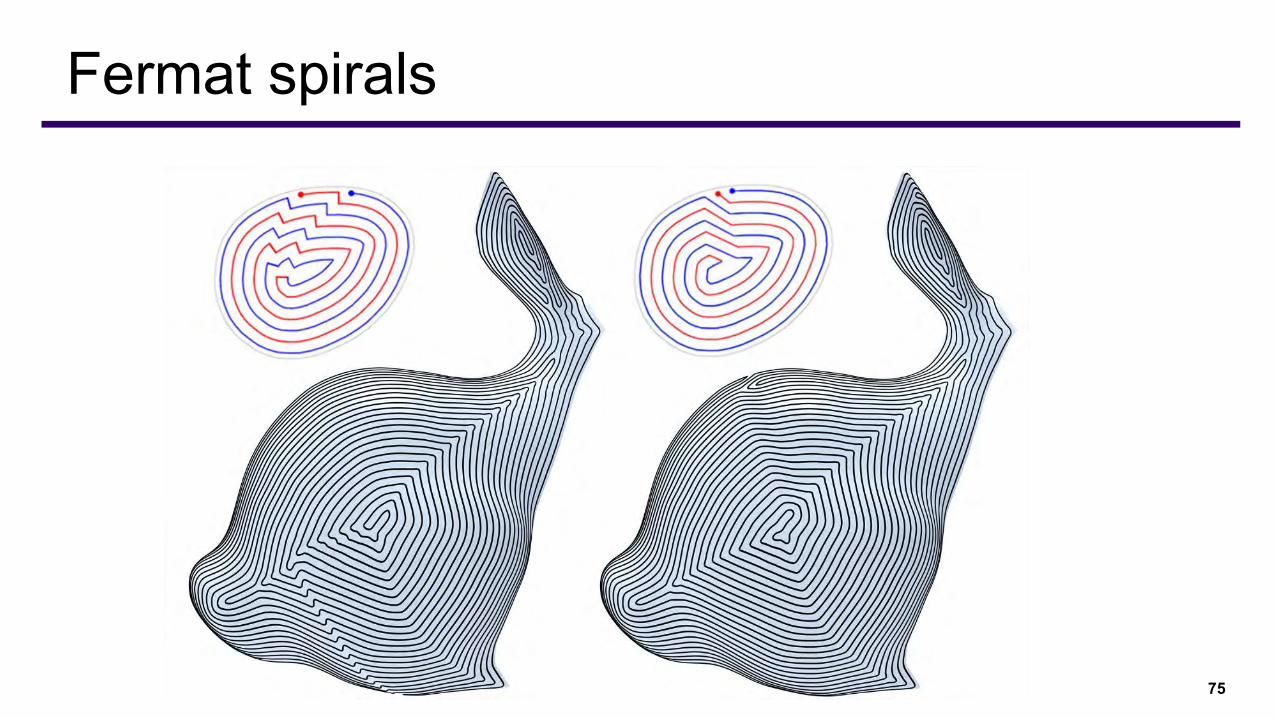
75
Fermat spirals
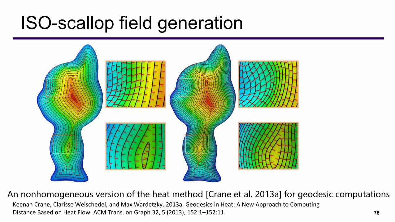
76
ISO-scallop field generation
An nonhomogeneous version of the heat method [Crane et al. 2013a] for geodesic computations Keenan Crane, Clarisse Weischedel, and Max Wardetzky. 2013a. Geodesics in Heat: A New Approach to Computing Distance Based on Heat Flow. ACM Trans. on Graph 32, 5 (2013), 152:1–152:11.
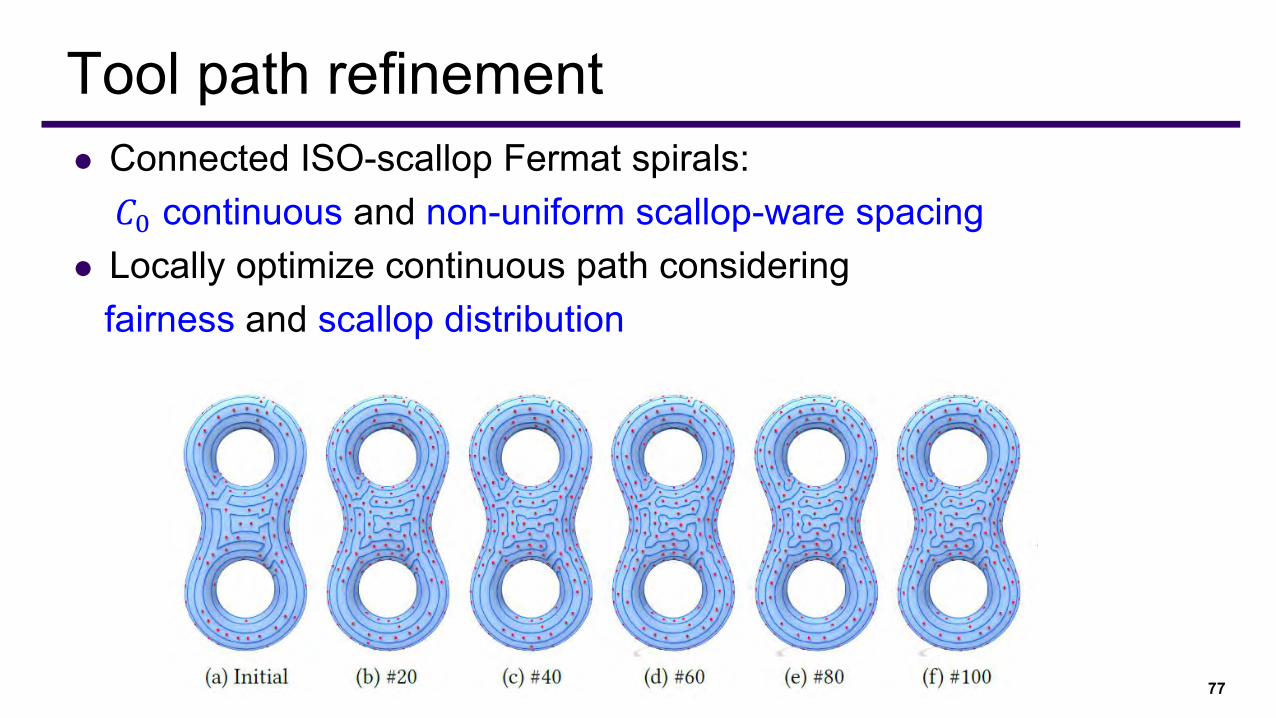
⚫ Connected ISO-scallop Fermat spirals: 𝐶0 continuous and non-uniform scallop-ware spacing
⚫ Locally optimize continuous path considering fairness and scallop distribution
77
Tool path refinement
78
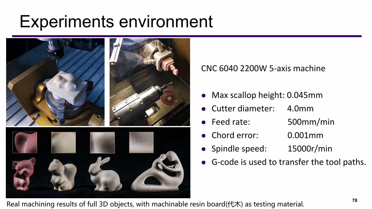
Experiments environment
CNC 6040 2200W 5-axis machine
⚫ Max scallop height: 0.045mm
⚫ Cutter diameter: 4.0mm
⚫ Feed rate: 500mm/min
⚫ Chord error: 0.001mm
⚫ Spindle speed: 15000r/min
⚫ G-code is used to transfer the tool paths.
Real machining results of full 3D objects, with machinable resin board(代木) as testing material.
79
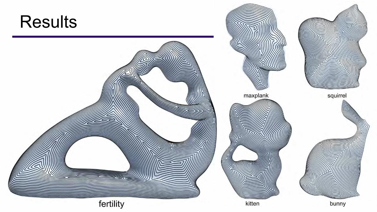
Results
80
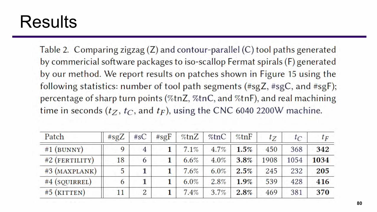
Results
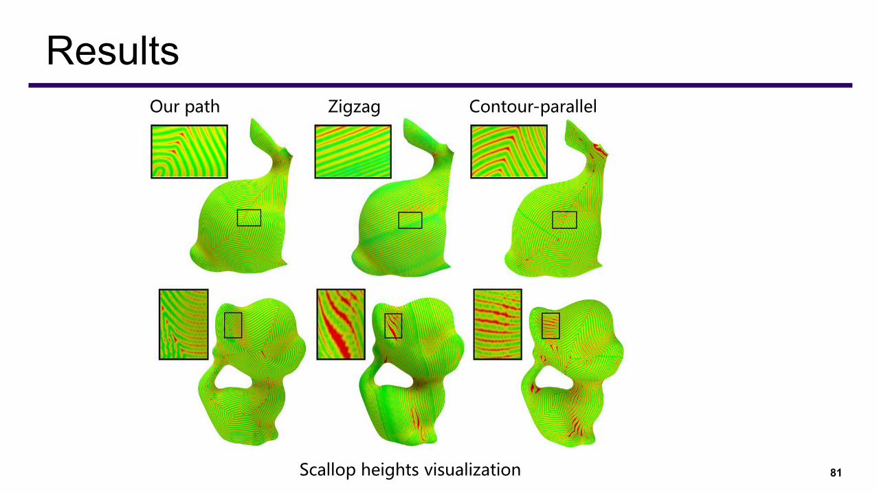
81
Results
Scallop heights visualization
Our path Zigzag Contour-parallel
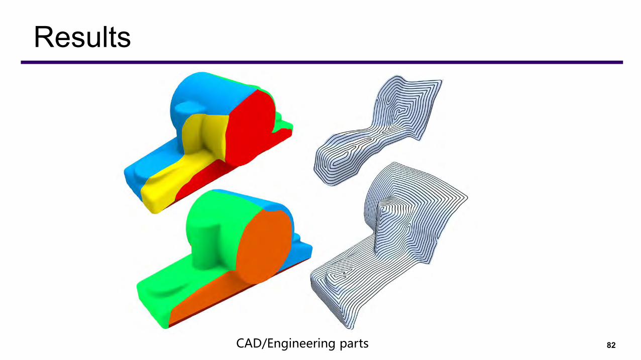
82
Results
CAD/Engineering parts
⚫ Practical CNC machining issues⚫ Fixture design, cutter switching
⚫ Overlook rough machining
⚫ Do not address inaccessibility from tunnels or hollow parts
⚫ Did not produce a globally continuous carving path for one setup
83
Limitation and future works
⚫ 4 axis machining ⚫ Rough machining⚫ Fixture design⚫ 机器人路径机械最短路径
⚫ 机器人喷漆
⚫ 石材切割问题(特种刀具)
⚫ 冷却水路设计
84
新的研究问题

85
4 axis machining
86
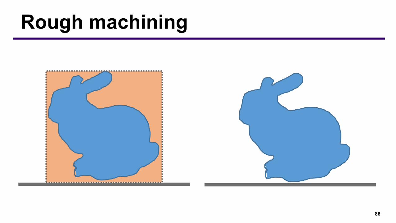
Rough machining
87
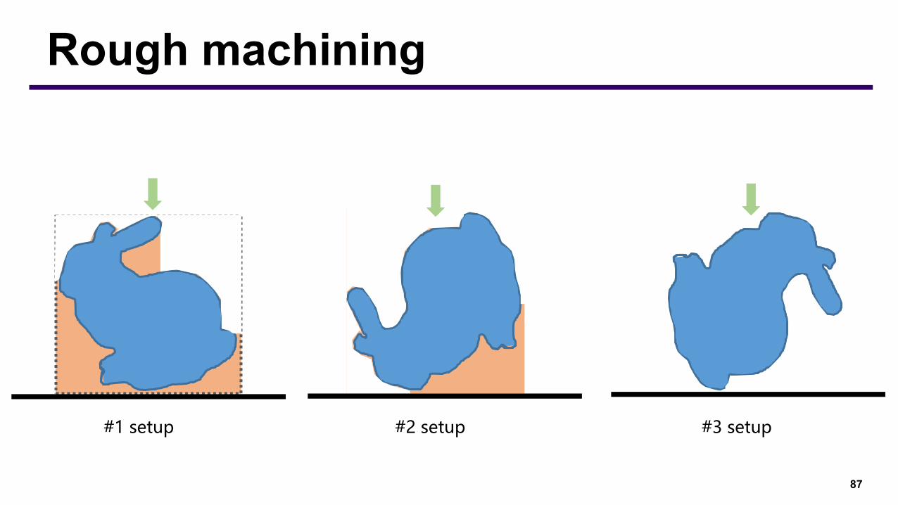
Rough machining
#1 setup #2 setup #3 setup

88
Rough machining
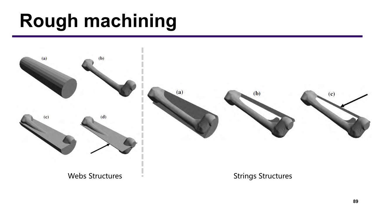
89
Rough machining
Webs Structures Strings Structures
90
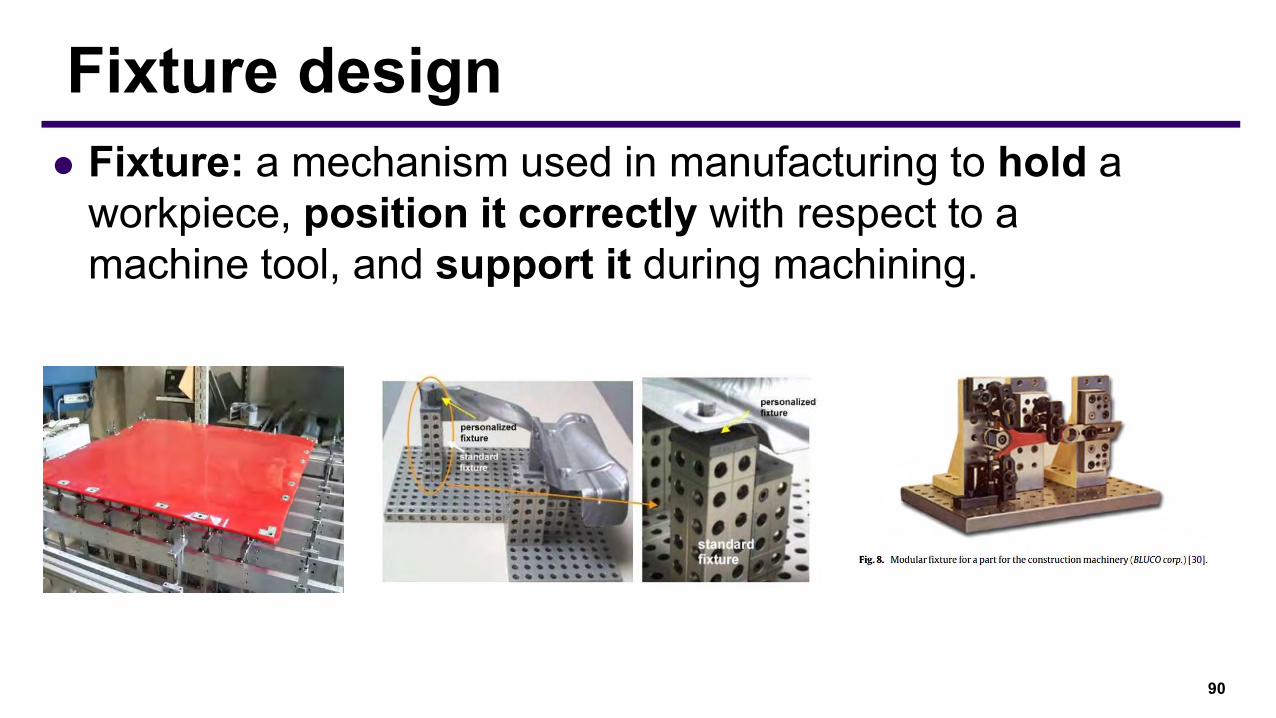
Fixture design⚫ Fixture: a mechanism used in manufacturing to hold a
workpiece, position it correctly with respect to a machine tool, and support it during machining.
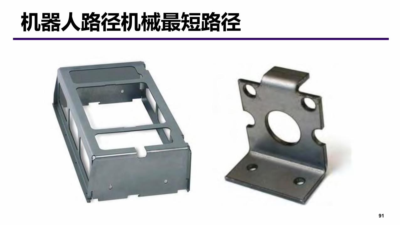
91
机器人路径机械最短路径
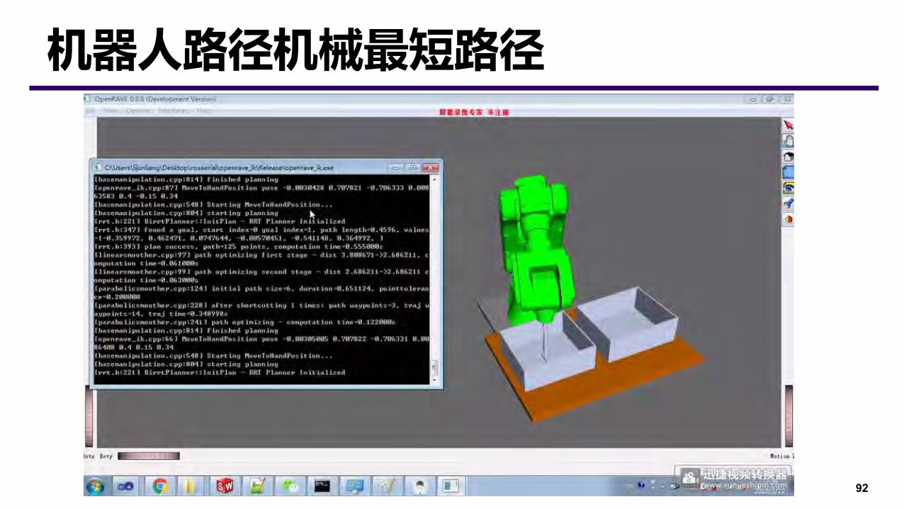
92
机器人路径机械最短路径
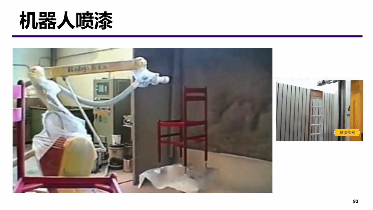
93
机器人喷漆
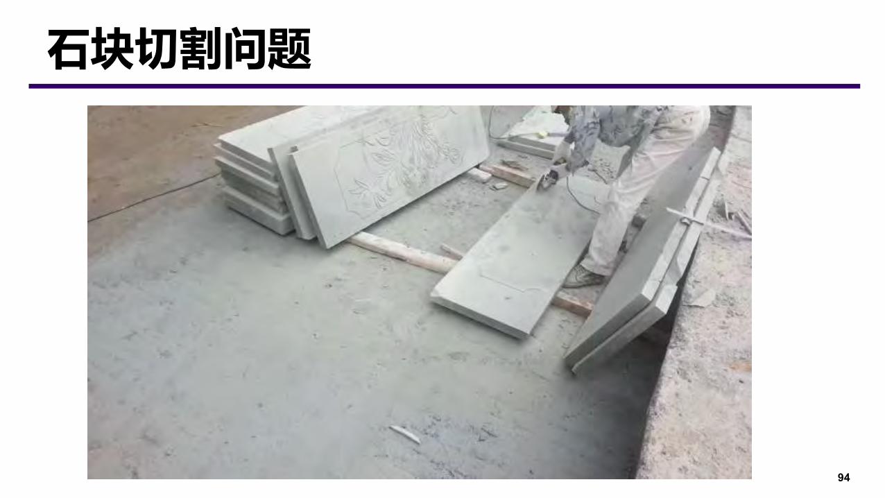
94
石块切割问题

95
石块切割问题
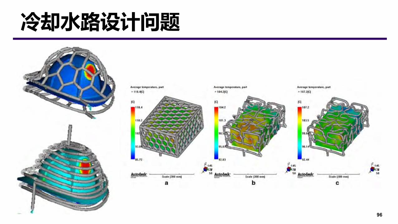
96
冷却水路设计问题

Subtractive Manufacturing


![New Iterative Methods for Interpolation, Numerical ... · and Aitken’s iterated interpolation formulas[11,12] are the most popular interpolation formulas for polynomial interpolation](https://img.pdfslide.us/doc/110x75/5ebfad147f604608c01bd287/new-iterative-methods-for-interpolation-numerical-and-aitkenas-iterated-interpolation.jpg)